EP3983036B1 - Gasevakuierungssystem mit einem leckagekontrollsystem für ein insufflationssystem - Google Patents
Gasevakuierungssystem mit einem leckagekontrollsystem für ein insufflationssystem Download PDFInfo
- Publication number
- EP3983036B1 EP3983036B1 EP20733399.8A EP20733399A EP3983036B1 EP 3983036 B1 EP3983036 B1 EP 3983036B1 EP 20733399 A EP20733399 A EP 20733399A EP 3983036 B1 EP3983036 B1 EP 3983036B1
- Authority
- EP
- European Patent Office
- Prior art keywords
- vessel
- evacuation system
- pressure
- vacuum creating
- valve
- Prior art date
- Legal status (The legal status is an assumption and is not a legal conclusion. Google has not performed a legal analysis and makes no representation as to the accuracy of the status listed.)
- Active
Links
Images


Classifications
-
- A—HUMAN NECESSITIES
- A61—MEDICAL OR VETERINARY SCIENCE; HYGIENE
- A61M—DEVICES FOR INTRODUCING MEDIA INTO, OR ONTO, THE BODY; DEVICES FOR TRANSDUCING BODY MEDIA OR FOR TAKING MEDIA FROM THE BODY; DEVICES FOR PRODUCING OR ENDING SLEEP OR STUPOR
- A61M13/00—Insufflators for therapeutic or disinfectant purposes, i.e. devices for blowing a gas, powder or vapour into the body
- A61M13/003—Blowing gases other than for carrying powders, e.g. for inflating, dilating or rinsing
-
- A—HUMAN NECESSITIES
- A61—MEDICAL OR VETERINARY SCIENCE; HYGIENE
- A61M—DEVICES FOR INTRODUCING MEDIA INTO, OR ONTO, THE BODY; DEVICES FOR TRANSDUCING BODY MEDIA OR FOR TAKING MEDIA FROM THE BODY; DEVICES FOR PRODUCING OR ENDING SLEEP OR STUPOR
- A61M16/00—Devices for influencing the respiratory system of patients by gas treatment, e.g. ventilators; Tracheal tubes
- A61M16/20—Valves specially adapted to medical respiratory devices
- A61M16/208—Non-controlled one-way valves, e.g. exhalation, check, pop-off non-rebreathing valves
- A61M16/209—Relief valves
-
- A—HUMAN NECESSITIES
- A61—MEDICAL OR VETERINARY SCIENCE; HYGIENE
- A61M—DEVICES FOR INTRODUCING MEDIA INTO, OR ONTO, THE BODY; DEVICES FOR TRANSDUCING BODY MEDIA OR FOR TAKING MEDIA FROM THE BODY; DEVICES FOR PRODUCING OR ENDING SLEEP OR STUPOR
- A61M39/00—Tubes, tube connectors, tube couplings, valves, access sites or the like, specially adapted for medical use
- A61M39/22—Valves or arrangement of valves
- A61M39/24—Check- or non-return valves
-
- A—HUMAN NECESSITIES
- A61—MEDICAL OR VETERINARY SCIENCE; HYGIENE
- A61B—DIAGNOSIS; SURGERY; IDENTIFICATION
- A61B18/00—Surgical instruments, devices or methods for transferring non-mechanical forms of energy to or from the body
- A61B18/02—Surgical instruments, devices or methods for transferring non-mechanical forms of energy to or from the body by cooling, e.g. cryogenic techniques
-
- A—HUMAN NECESSITIES
- A61—MEDICAL OR VETERINARY SCIENCE; HYGIENE
- A61B—DIAGNOSIS; SURGERY; IDENTIFICATION
- A61B2218/00—Details of surgical instruments, devices or methods for transferring non-mechanical forms of energy to or from the body
- A61B2218/001—Details of surgical instruments, devices or methods for transferring non-mechanical forms of energy to or from the body having means for irrigation and/or aspiration of substances to and/or from the surgical site
- A61B2218/002—Irrigation
- A61B2218/006—Irrigation for smoke evacuation
-
- A—HUMAN NECESSITIES
- A61—MEDICAL OR VETERINARY SCIENCE; HYGIENE
- A61M—DEVICES FOR INTRODUCING MEDIA INTO, OR ONTO, THE BODY; DEVICES FOR TRANSDUCING BODY MEDIA OR FOR TAKING MEDIA FROM THE BODY; DEVICES FOR PRODUCING OR ENDING SLEEP OR STUPOR
- A61M16/00—Devices for influencing the respiratory system of patients by gas treatment, e.g. ventilators; Tracheal tubes
- A61M16/0087—Environmental safety or protection means, e.g. preventing explosion
- A61M16/009—Removing used or expired gases or anaesthetic vapours
-
- A—HUMAN NECESSITIES
- A61—MEDICAL OR VETERINARY SCIENCE; HYGIENE
- A61M—DEVICES FOR INTRODUCING MEDIA INTO, OR ONTO, THE BODY; DEVICES FOR TRANSDUCING BODY MEDIA OR FOR TAKING MEDIA FROM THE BODY; DEVICES FOR PRODUCING OR ENDING SLEEP OR STUPOR
- A61M16/00—Devices for influencing the respiratory system of patients by gas treatment, e.g. ventilators; Tracheal tubes
- A61M16/08—Bellows; Connecting tubes ; Water traps; Patient circuits
- A61M16/0816—Joints or connectors
- A61M16/0841—Joints or connectors for sampling
- A61M16/0858—Pressure sampling ports
-
- A—HUMAN NECESSITIES
- A61—MEDICAL OR VETERINARY SCIENCE; HYGIENE
- A61M—DEVICES FOR INTRODUCING MEDIA INTO, OR ONTO, THE BODY; DEVICES FOR TRANSDUCING BODY MEDIA OR FOR TAKING MEDIA FROM THE BODY; DEVICES FOR PRODUCING OR ENDING SLEEP OR STUPOR
- A61M16/00—Devices for influencing the respiratory system of patients by gas treatment, e.g. ventilators; Tracheal tubes
- A61M16/20—Valves specially adapted to medical respiratory devices
- A61M16/201—Controlled valves
- A61M16/202—Controlled valves electrically actuated
-
- A—HUMAN NECESSITIES
- A61—MEDICAL OR VETERINARY SCIENCE; HYGIENE
- A61M—DEVICES FOR INTRODUCING MEDIA INTO, OR ONTO, THE BODY; DEVICES FOR TRANSDUCING BODY MEDIA OR FOR TAKING MEDIA FROM THE BODY; DEVICES FOR PRODUCING OR ENDING SLEEP OR STUPOR
- A61M16/00—Devices for influencing the respiratory system of patients by gas treatment, e.g. ventilators; Tracheal tubes
- A61M16/0003—Accessories therefor, e.g. sensors, vibrators, negative pressure
- A61M2016/0027—Accessories therefor, e.g. sensors, vibrators, negative pressure pressure meter
-
- A—HUMAN NECESSITIES
- A61—MEDICAL OR VETERINARY SCIENCE; HYGIENE
- A61M—DEVICES FOR INTRODUCING MEDIA INTO, OR ONTO, THE BODY; DEVICES FOR TRANSDUCING BODY MEDIA OR FOR TAKING MEDIA FROM THE BODY; DEVICES FOR PRODUCING OR ENDING SLEEP OR STUPOR
- A61M39/00—Tubes, tube connectors, tube couplings, valves, access sites or the like, specially adapted for medical use
- A61M39/22—Valves or arrangement of valves
- A61M39/24—Check- or non-return valves
- A61M2039/242—Check- or non-return valves designed to open when a predetermined pressure or flow rate has been reached, e.g. check valve actuated by fluid
-
- A—HUMAN NECESSITIES
- A61—MEDICAL OR VETERINARY SCIENCE; HYGIENE
- A61M—DEVICES FOR INTRODUCING MEDIA INTO, OR ONTO, THE BODY; DEVICES FOR TRANSDUCING BODY MEDIA OR FOR TAKING MEDIA FROM THE BODY; DEVICES FOR PRODUCING OR ENDING SLEEP OR STUPOR
- A61M2202/00—Special media to be introduced, removed or treated
- A61M2202/02—Gases
- A61M2202/0225—Carbon oxides, e.g. Carbon dioxide
-
- A—HUMAN NECESSITIES
- A61—MEDICAL OR VETERINARY SCIENCE; HYGIENE
- A61M—DEVICES FOR INTRODUCING MEDIA INTO, OR ONTO, THE BODY; DEVICES FOR TRANSDUCING BODY MEDIA OR FOR TAKING MEDIA FROM THE BODY; DEVICES FOR PRODUCING OR ENDING SLEEP OR STUPOR
- A61M2205/00—General characteristics of the apparatus
- A61M2205/07—General characteristics of the apparatus having air pumping means
- A61M2205/071—General characteristics of the apparatus having air pumping means hand operated
-
- A—HUMAN NECESSITIES
- A61—MEDICAL OR VETERINARY SCIENCE; HYGIENE
- A61M—DEVICES FOR INTRODUCING MEDIA INTO, OR ONTO, THE BODY; DEVICES FOR TRANSDUCING BODY MEDIA OR FOR TAKING MEDIA FROM THE BODY; DEVICES FOR PRODUCING OR ENDING SLEEP OR STUPOR
- A61M2205/00—General characteristics of the apparatus
- A61M2205/07—General characteristics of the apparatus having air pumping means
- A61M2205/078—General characteristics of the apparatus having air pumping means foot operated
-
- A—HUMAN NECESSITIES
- A61—MEDICAL OR VETERINARY SCIENCE; HYGIENE
- A61M—DEVICES FOR INTRODUCING MEDIA INTO, OR ONTO, THE BODY; DEVICES FOR TRANSDUCING BODY MEDIA OR FOR TAKING MEDIA FROM THE BODY; DEVICES FOR PRODUCING OR ENDING SLEEP OR STUPOR
- A61M2205/00—General characteristics of the apparatus
- A61M2205/33—Controlling, regulating or measuring
- A61M2205/3331—Pressure; Flow
- A61M2205/3334—Measuring or controlling the flow rate
-
- A—HUMAN NECESSITIES
- A61—MEDICAL OR VETERINARY SCIENCE; HYGIENE
- A61M—DEVICES FOR INTRODUCING MEDIA INTO, OR ONTO, THE BODY; DEVICES FOR TRANSDUCING BODY MEDIA OR FOR TAKING MEDIA FROM THE BODY; DEVICES FOR PRODUCING OR ENDING SLEEP OR STUPOR
- A61M2205/00—General characteristics of the apparatus
- A61M2205/33—Controlling, regulating or measuring
- A61M2205/3331—Pressure; Flow
- A61M2205/3344—Measuring or controlling pressure at the body treatment site
-
- A—HUMAN NECESSITIES
- A61—MEDICAL OR VETERINARY SCIENCE; HYGIENE
- A61M—DEVICES FOR INTRODUCING MEDIA INTO, OR ONTO, THE BODY; DEVICES FOR TRANSDUCING BODY MEDIA OR FOR TAKING MEDIA FROM THE BODY; DEVICES FOR PRODUCING OR ENDING SLEEP OR STUPOR
- A61M2205/00—General characteristics of the apparatus
- A61M2205/75—General characteristics of the apparatus with filters
- A61M2205/7509—General characteristics of the apparatus with filters for virus
-
- A—HUMAN NECESSITIES
- A61—MEDICAL OR VETERINARY SCIENCE; HYGIENE
- A61M—DEVICES FOR INTRODUCING MEDIA INTO, OR ONTO, THE BODY; DEVICES FOR TRANSDUCING BODY MEDIA OR FOR TAKING MEDIA FROM THE BODY; DEVICES FOR PRODUCING OR ENDING SLEEP OR STUPOR
- A61M2205/00—General characteristics of the apparatus
- A61M2205/75—General characteristics of the apparatus with filters
- A61M2205/7518—General characteristics of the apparatus with filters bacterial
-
- A—HUMAN NECESSITIES
- A61—MEDICAL OR VETERINARY SCIENCE; HYGIENE
- A61M—DEVICES FOR INTRODUCING MEDIA INTO, OR ONTO, THE BODY; DEVICES FOR TRANSDUCING BODY MEDIA OR FOR TAKING MEDIA FROM THE BODY; DEVICES FOR PRODUCING OR ENDING SLEEP OR STUPOR
- A61M2206/00—Characteristics of a physical parameter; associated device therefor
- A61M2206/10—Flow characteristics
- A61M2206/20—Flow characteristics having means for promoting or enhancing the flow, actively or passively
Definitions
- the present invention relates to an evacuation system for an insufflation system, and in particular to an evacuation system for minimising leakage of insufflating gas through a vessel evacuation system of an insufflation system.
- the invention also relates to an insufflation system.
- Insufflation systems are used for insufflating a cavity, vessel or lumen in which a surgical or investigative procedure is being carried out, for example, by laparoscopic surgery or by other appropriate minimal invasive surgical or investigative means.
- the cavity, vessel or lumen is maintained insufflated by the insufflation system, which delivers an insufflating gas into the cavity, vessel or lumen.
- Pressure in the cavity, vessel or lumen is monitored during the insufflating thereof, and the flow of the insufflating gas delivered by the insufflation system to the cavity, vessel or lumen is controlled in response to the monitored pressure, in order to maintain the pressure of the insufflating gas in the cavity, vessel or lumen at a predefined pressure, which typically, is selectable.
- the pressure of the insufflating gas in the cavity, vessel or lumen is relatively low, for example, at the commencement of insufflating of the cavity, vessel or lumen, the flow rate at which the insufflating gas is delivered to the cavity, vessel or lumen by the insufflation system is relatively high.
- This can be problematical if the pressure of the insufflating gas in the cavity, vessel or lumen reaches the predefined pressure relatively quickly, since it is possible that before the insufflating gas can be throttled back or isolated from the cavity, vessel or lumen, the pressure in the cavity, vessel or lumen may have significantly exceeded the predefined pressure. This would be so, particularly in the case of a relatively small cavity, vessel or lumen.
- Such evacuation systems in general include a vacuum creating means, for example, a Venturi vacuum creating means comprising a Venturi throat, in which the vacuum is created.
- the vacuum creating Venturi throat is connected through an evacuating conduit to the cavity, vessel or lumen for drawing a vacuum in the cavity, vessel or lumen, to in turn draw the smoke or other gases from the cavity, vessel or lumen.
- the evacuating conduit may be entered into or connected to the cavity, vessel or lumen through, for example, a trocar, a Veress needle, a cannula or other suitable connecting means.
- the Venturi vacuum creating device creates a vacuum in the Venturi throat of approximately 50mmHg.
- WO 2012/058720 of Esnouf discloses a portable suction device for clearing the airways of a subject.
- the suction device comprises a vacuum generator and a suction tube terminating in a distal end for insertion into the airways of a subject.
- a proximal end of the suction tube terminates in a one-way vale in a container for containing fluid suctioned from the subject.
- the vacuum generator is connected to the container for applying a vacuum to the container for in turn applying a vacuum to the suction tube for suctioning the airways of a subject.
- the one-way valve located at the distal end of the suction tube is configured to permit flow through the suction tube in the direction to the vacuum generator, but to inhibit flow in the reverse direction in order to avoid syphoning of the contents of the suction tube back into the airways of the subject.
- WO 2017/177069 of Minskoff et al discloses a suction device comprising a low-pressure suction port for connecting to a cavity in which debris, gas and the like is to be suctioned.
- the suction port is connected through a backflow prevention valve to a vacuum generator.
- the vacuum generator is configured to draw debris and other matter through the suction port and in turn through the backflow prevention valve, which is then discharged through a waste outlet port.
- the backflow prevention valve is provided to prevent backflow of positive pressure gas which is used to generate the vacuum in the vacuum generator to the low-pressure suction port.
- the present invention is directed towards providing such an evacuation system and an insufflation system.
- an evacuation system for an insufflation system comprising a vacuum creating means for communicating with a vessel being insufflated by the insufflation system, the vacuum creating means communicating with the vessel through a flow path for accommodating insufflating gas from the vessel, the evacuation system further comprising a leak control system for minimising leakage of insufflating gas from the vessel through the evacuation system when the evacuation system is deactivated, wherein said leak control system comprises a pressure relief valve located in the flow path of the evacuation system upstream of the vacuum creating means, said pressure relief valve being operable from a closed state preventing gas flow to the vacuum creating means through the flow path, to an open state permitting gas flow to the vacuum creating means through the flow path in response to a pressure drop across the pressure relief valve in the direction of flow to the vacuum creating means exceeding a predefined pressure drop value.
- the pressure relief valve is directly responsive to the pressure drop across the pressure relief valve exceeding the predefined pressure drop value in the direction of flow to the vacuum creating means to transition from the closed state to the open state.
- the pressure relief valve comprises a valve seat defining a valve orifice therethrough for accommodating gas therethrough to the vacuum creating means, and a valving element operable between a closed state sealably engaging the valve seat to close the valve orifice with the valve in the closed state, and an open state spaced apart from the valve seat to open the valve orifice with the valve in the open state.
- the valve seat extends around the valve orifice.
- the valving element is located on the downstream side of the valve seat.
- the valving element is urgeable into the closed state by an urging means acting against the direction of flow to the vacuum creating means.
- the urging means is configured to urge the valving element into the closed state with a force sufficient to maintain the valving element in the closed state until the pressure drop across the valving element in the direction of flow to the vacuum creating means exceeds the predefined pressure drop value.
- the urging means is configured to act on the valving element for urging the valving element into the closed state.
- the urging means is configured to act directly on the valving element for urging the valving element into the closed state.
- the urging means comprises a passive urging means.
- the urging means comprises a spring urging means.
- the urging means comprises a spring.
- the urging means comprises a compression spring.
- the pressure relief valve is adjustable for selectively varying the predefined pressure drop value to which the pressure relief valve is responsive.
- the urging means is adjustable for selectively varying the predefined pressure drop value to which the pressure relief valve is responsive.
- the urging means is adjustable for selectively varying the force with which the urging means urges the valving element into the closed state.
- the urging means acts against an anchoring means for urging the valving element into the closed state.
- the urging means is located between the anchoring means and the valving element.
- the urging means acts between the anchoring means and the valving element.
- the anchoring means is moveable for varying the force with which the urging means urges the valving element into the closed state.
- the anchoring means is moveable relative to the valving element for varying the force with which the urging means urges the valving element into the closed state.
- the anchoring means is moveable relative to the valving element for varying the spacing between the anchoring means and the valving element.
- a means for moving the anchoring means is provided.
- the means for moving the anchoring means comprises a manually operable moving means.
- the pressure relief valve comprises a housing defining a hollow interior region, a partition wall located in the hollow interior region of the housing dividing the hollow interior region into an upstream valve chamber and a downstream valve chamber, the valve orifice being formed in the partition wall and communicating the downstream valve chamber with the upstream valve chamber, an inlet port to the upstream valve chamber configured for connecting to the flow path on the upstream side of the pressure relief valve, and an outlet port from the downstream valve chamber configured for connecting to the flow path on the downstream side of the pressure relief valve.
- the urging means is located in the downstream valve chamber, and acts on the valving element in an upstream direction.
- the anchoring means is located in the downstream valve chamber.
- the means for moving the anchoring means is accessible externally of the housing.
- an evacuating conduit is provided, the evacuating conduit defining the flow path and terminating in an upstream end configured for receiving the insufflating gas from a vessel being insufflated.
- the upstream end of the evacuating conduit is configured for communicating with the vessel.
- the upstream end of the evacuating conduit is configured for communicating with the vessel through one of a trocar, a cannula and a Veress needle.
- the evacuating conduit is configured for receiving insufflating gas and other gases from a vessel being insufflated.
- the evacuating conduit is configured for receiving insufflating gas and other gases from an adjacent vessel adjacent the vessel being insufflated.
- the evacuating conduit is configured for communicating with the vacuum creating means of the vessel provided for delivering the insufflating gas from the evacuation system.
- the pressure relief valve is located in the evacuation conduit.
- the predefined pressure drop value lies in the range of 5mmHg to 1000mmHg.
- the predefined pressure drop value lies in the range of 1 0mmHg to 500mmHg.
- the predefined pressure drop value lies in the range of 15mmHg to 50mmHg.
- the predefined pressure drop value lies in the range of 20mmHg to 30mmHg.
- the predefined pressure drop value is approximately 25mmHg.
- the vacuum creating means is configured to generate a vacuum down to 30mmHg below atmospheric pressure.
- the vacuum creating means is configured to generate a vacuum down to 50mmHg below atmospheric pressure.
- the vacuum creating means is configured to generate a vacuum down to 500mmHg below atmospheric pressure.
- the vacuum creating means is configured to generate a vacuum down to 1000mmHg below atmospheric pressure.
- the vacuum creating means comprises a Venturi vacuum creating device.
- the flow path for accommodating the insufflating gas from the vessel terminates in a vacuum generating throat of the Venturi vacuum creating device.
- the vacuum creating means is responsive to one of a signal generated in response to pressure in the vessel being insufflated exceeding a predefined pressure value, and an externally generated signal.
- the signal generated in response to the pressure in the vessel being insufflated exceeding the predefined pressure is generated by a pressure monitoring means.
- the signal generated in response to the pressure in the vessel being insufflated exceeding the predefined pressure is generated by a pressure sensor.
- the signal generated in response to the pressure in the vessel being insufflated exceeding the predefined pressure is generated by the pressure monitoring means located in one of the vessel and remotely thereof.
- the signal generated in response to the pressure in the vessel being insufflated exceeding the predefined pressure is produced by the insufflation system.
- the externally generated signal comprises one of a manually generated signal, and a signal generated in response to activation of a surgical instrument.
- the manually generated signal is generated by one of a foot operable switch and a hand operable switch.
- the manually generated signal is generated by both a foot operable switch and a hand operable switch.
- the signal generated in response to activation of a surgical instrument is generated in response to a surgical instrument located in the vessel.
- the signal generated in response to activation of a surgical instrument is generated in response to one of a cauterising instrument and a freezing instrument.
- the signal generated in response to activation of a surgical instrument is generated in response to the cauterising instrument being activated.
- the signal generated in response to activation of a surgical instrument is generated in response to the freezing instrument being activated.
- the freezing instrument comprises an instrument configured to deliver a liquid gas to a site to be frozen.
- the predefined pressure lies in the range of 5mmHg to 50mmHg.
- the predefined pressure lies in the range of 1 0mmHg to 50mmHg.
- the predefined pressure lies in the range of 15mmHg to 50mmHg.
- the predefined pressure lies in the range of 20mmHg to 30mmHg, and ideally, the predefined pressure is approximately 25mmHg.
- the invention provides an insufflation system for supplying an insufflating gas to a vessel of a subject, the insufflation system comprising an evacuation system according to the invention for evacuating insufflating gas from the vessel through the flow path of the evacuation system.
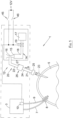
- the insufflation system 1 comprises and insufflator 3 for insufflating a vessel 5 of a human or animal subject with an insufflating gas and for controlling the flow rate of the insufflating gas to the vessel 1.
- the vessel 1 may be any cavity, vessel or lumen in a human or animal body, for example, an abdominal cavity, a rectum, a large intestine, a small intestine, a stomach, or any other cavity, vessel or lumen.
- the insufflating gas may be any suitable gas, and typically, is carbon dioxide.
- the insufflator 3 sets and controls the pressure at which the insufflating gas is delivered from the insufflator 3 to the vessel 5, and also controls the flow rate of insufflating gas from the insufflator 3 to the vessel 5.
- Such insufflators as the insufflator 3 will be well known to those skilled in the art, and further description should not be required.
- An insufflating conduit 7 extending from the insufflator 3 accommodates the insufflating gas to the vessel 5.
- the insufflating conduit 7 either extends into the vessel 5 through a trocar 8, or may be connected to a trocar, which in turn would accommodate the insufflating gas from the insufflating conduit 7 into the vessel 5.
- Such arrangements for delivering a insufflating gas from an insufflator through an insufflating conduit to a vessel during insufflating thereof will be well known to those skilled in the art.
- a pressure conduit 9 extends from the insufflator 3 and into the vessel 5 through the trocar 8, or may be connected to the trocar or may extend into the vessel 5 through another trocar, cannula or a Veress needle. Such arrangements for connecting a pressure conduit with a vessel being insufflated will be well known to those skilled in the art.
- the pressure conduit 9, connects the vessel 5 to a pressure sensor 10 located in the insufflator 3.
- the gas in the pressure conduit 9 is static, so that the pressure read by the pressure sensor 10 provides a true reading of the static pressure of the insufflating gas in the vessel 5.
- the insufflator 3 controls the flowrate of the insufflating gas to the vessel 5 in response to the pressure read from the pressure sensor 10 for maintaining the pressure of the insufflating gas in the vessel 5 at a predefined pressure value, which in this embodiment of the invention is approximately 25mmHg.
- the predefined pressure may be selectable, and would be selected based on the nature of the vessel being insufflated.
- pressures to which vessels are insufflated range from 5mmHg to 30mmHg, depending on the vessel being insufflated, although in some cases vessels may be insufflated to pressures up to 50mmHg.
- the evacuation system 12 comprises a vacuum creating means, which in this embodiment of the invention comprises a Venturi vacuum creating device 14.
- the Venturi vacuum creating device 14 comprises a Venturi element 15 defining a Venturi throat 16. Gas at high velocity is delivered through the Venturi element 15 from a compressed gas source 17, which may, for example, be a compressed air source. Gas from the compressed gas source 17 is delivered to the Venturi element 15 through a delivery conduit 18 under the control of a solenoid operated valve 19.
- the high velocity gas passing through the Venturi element 15 generates a vacuum in the Venturi throat 16, which in this embodiment of the invention is approximately 50mmHg below atmospheric pressure, although, it is envisaged that in some embodiments of the invention the vacuum generated by the Venturi vacuum creating device may be down to 500mmHg and even down to 1000mmHg below atmospheric pressure.
- An evacuating conduit 20 comprising an upstream portion 21 and a downstream portion 22 communicates the Venturi throat 16 of the Venturi element 15 with the vessel 5.
- the evacuating conduit 20 is inserted into the vessel 5 through a trocar, but in this embodiment of the invention the upstream portion 21 of the evacuating conduit 20 communicates with the vessel 5 through a Veress needle 23.
- the evacuating conduit 20 defines a flow path 24 therethrough, through which the Venturi throat 16 communicates with the vessel 5 for evacuating insufflating gas and other gases from the vessel 5 in the direction of the arrow A.
- gases may, for example, be smoke which may be generated by cauterising tissue and the like within the vessel 5, or by cauterising other vessels, lumen or organs located in the vessel 5.
- gases may comprise, for example, nitrogen gas or other gases at relatively high pressures evaporating from liquid nitrogen or the liquid phase or other gases delivered into the vessel 5 of the subject in the liquid phase for freezing a site, tissue, a lumen or organ in the vessel 5, which could result in a rapid rise in pressure in the vessel 5 as the liquid phase of the gas transitions from the liquid phase to the gaseous phase.
- gases may, for example, be noxious gases or other noxious by-product gases found in the vessel 5.
- a filter 25 located in the flow path 24 defined by the evacuating conduit 20 filters out any such noxious gases and other noxious by-products contained in the insufflating gas or smoke being drawn from the vessel 5 in the direction of the arrow A under the vacuum from the Venturi vacuum creating device 14. Additionally, the filter 25 is configured to filter out particulate matter entrained in the gas, such as organisms, for example, pathogens, infections, viruses, and the like.
- a leak control system indicated generally by the reference numeral 26 for minimising leakage of insufflating gas from the vessel 5 through the evacuation system 12 when the evacuation system 12 is deactivated comprises a pressure relief valve 27.
- the pressure relief valve 27 is located in the flow path 24 defined by the evacuating conduit 20 between the vessel 5 and the vacuum creating device 14 and upstream of the vacuum creating device 14, and downstream of the filter 25.
- the pressure relief valve 27 is operable from a closed state illustrated in Fig. 2 for preventing gas flow through the flow path 24 defined through the evacuating conduit 20, and thereby isolating the vessel 5 from the Venturi vacuum creating device 14, to an open state illustrated in Fig.
- the pressure relief valve 27 is responsive to a pressure drop developed across the pressure relief valve 27 in the direction of flow from the vessel 5 to the Venturi vacuum creating device 14, namely, in the direction of the arrow A, exceeding a predefined pressure drop value, which is discussed in more detail below, for operating from the closed state to the open state.
- the pressure relief valve 27 comprises a valve housing 28 defining a hollow interior region, which forms a valve chamber 29.
- a partition wall 30 divides the valve chamber 29 into an upstream valve chamber 31 and a downstream valve chamber 32.
- a valve orifice 34 extending through the partition wall 30 communicates the downstream valve chamber 32 with the upstream valve chamber 31.
- a valve seat 35 extends around the valve orifice 34 for sealably engaging a valving element 36.
- the valving element 36 is urgeable in a generally upstream direction, namely, in the direction of the arrow B from an open state with the pressure relief valve 27 in the open state of Fig. 3 , into a closed state sealably engaging the valve seat 35 with the pressure relief valve 27 in the closed state of Fig. 2 .
- An urging means which in this embodiment of the invention comprises a passive urging means, namely, a spring urging means, provided by a compression spring 38 urges the valving element 36 into the closed state sealably engaging the valve seat 35.
- the compression spring 38 acts between the valving element 36 and an anchoring means, which in this embodiment of the invention comprises a downstream end wall 39 of the valve housing 28 for releasably retaining the valving element 36 in the closed state.
- An inlet port 40 extending from an upstream end wall 41 of the valve housing 28 is connected to the upstream portion 21 of the evacuating conduit 20 for communicating the upstream valve chamber 31 through the filter 25 to the vessel 5.
- An outlet port 42 extending from the downstream end wall 39 of the valve housing 28 is connected to the downstream portion 22 of the evacuating conduit 20, for communicating the downstream valve chamber 32 to the Venturi throat 16 of the Venturi vacuum device 14.
- the compression spring 38 is configured to urge the valving element 36 into the closed state to sealably engage the valve seat 35 with a force F1.
- the value of the force F1 acting on the valving element 36 when the valving element 36 is in the closed state is sufficient to retain the valving element 36 in the closed state until the pressure drop across the valving element 36 in the direction of gas flow from the vessel 5 to the Venturi vacuum creating device 14, namely, in the direction of the arrow A, exceeds the predefined pressure drop value, which in this embodiment of the invention is approximately 25mmHg.
- the compression spring 38 yields thereby permitting the valving element 36 to be urged by the pressure drop across the valving element 36 in the direction of the arrow A from the closed state to the open state spaced apart from the valve seat 35 with the pressure relief valve 27 in the open state to thereby communicate the vessel 5 with the Venturi throat 16 of the Venturi vacuum creating device 14 for the evacuation of insufflating gases together with smoke and other gases to be drawn from the vessel 5 under vacuum by the Venturi vacuum creating device 14.
- the value of the force F, applied by the compression spring 38 to the valving element 36 is described in more detail below.
- the solenoid operated valve 19 is responsive to a control signal generated in response to the pressure in the vessel 5 exceeding the predefined pressure value, or either of two externally generated control signals for applying gas from the compressed gas source 17 to the Venturi element 15.
- the control signal generated in response to the pressure in the vessel 5 exceeding the predefined pressure value is derived from the pressure sensor 10, which produces the control signal in response to the pressure monitored by the pressure sensor 10 being indicative of the pressure of the insufflating gas in the vessel 5 exceeding the predefined pressure value of approximately 25mmHg.
- the control signal from the pressure sensor 10 is applied to the solenoid operated valve 19 in order to operate the solenoid operated valve 19 into the open state, to apply the compressed gas to the Venturi element 15, and to retain the solenoid operated valve 19 in the open state for so long as the control signal is being outputted by the pressure sensor 10.
- One of the externally generated control signals is produced by a foot operated switch 45, and the other one of the externally generated control signals is generated by a hand operated switch 46, and are both applied to the solenoid operated valve 19.
- the foot operated switch 45 may be operated by foot by a surgeon wishing to activate the Venturi vacuum creating device 14, in order to extract gas from the vessel 5 or to reduce the pressure of the insufflating gas in the vessel 5.
- the hand operated switch 46 may be operated by hand by a surgeon, likewise wishing to extract gas from the vessel 5 or to reduce the pressure of the insufflating gas in the vessel 5.
- the foot operated switch 45 and the hand operated switch 46 are configured, so that when either one of them is operated into the closed state, a 12 volt or other suitable voltage supply is applied to the solenoid operated valve 19, in order to operate the solenoid valve 19 into the open state to apply the compressed gas to the Venturi element 15, and to retain the solenoid valve 19 in the open state for so long as either the foot operated switch 45 or the hand operated switch 46 is held in the closed state.
- the urging force F1 must therefore be equal to the force produced by the predefined pressure drop value of approximately 25mmHg.
- F2 P u ⁇ A u
- F3 P d ⁇ A d
- the pressure relief valve 27 In use, during insufflating of the vessel 5 by the insufflation system 1, the pressure relief valve 27 remains in the closed state until the pressure drop across the pressure relief valve 27 in the direction of the arrow A exceeds the value of the predefined pressure drop of 25mmHg.
- the pressure drop across the pressure relief valve 27 can exceed 25mmHg under two fundamental conditions. Firstly, when the Venturi vacuum creating device 14 is deactivated, and the pressure in the upstream chamber 31 of the pressure relief valve 27 exceeds 25mmHg, which in this case would arise in the event of the pressure in the vessel 5 exceeding the predefined pressure value of 25mmHg.
- the pressure relief valve 25 In normal use, the value of the pressure P u , namely, the pressure in the vessel 5 should not exceed 15mmHg, and therefore, the pressure relief valve 25 will only open when the Venturi vacuum creating device 14 is activated. However, in the event of the pressure in the vessel 5 exceeding a pressure equal to the predefined pressure value of 25mmHg, and if the pressure sensor 10 fails to produce the control signal, or if the Venturi vacuum creating device 14 fails to receive the control signal from the pressure sensor 10, or if the Venturi vacuum creating device 14 fails, the pressure relief valve 27 will operate from the closed state to the open state due to the pressure drop across the pressure relief valve 27 exceeding the predefined pressure drop value. Accordingly, the pressure relief valve 27 also acts as a failsafe device to relieve the pressure in the vessel 5, in the event of failure of the pressure sensor 10 or failure of the Venturi vacuum creating device 14.
- the leak control system 26 prevents insufflating gas leaking through the Venturi vacuum creating device 14 when the Venturi vacuum creating device 14 is deactivated, unless the pressure in the vessel 5 exceeds the predefined pressure drop value. For so long as the pressure of the insufflating gas in the vessel 5 remains below the predefined pressure value of 25mmHg, and the Venturi vacuum creating device 14 remains deactivated, the pressure relief valve 27 remains in the closed state, thereby preventing any leaking of the insufflating gas through the Venturi vacuum creating device 14.
- the insufflating gas is only lost through the Venturi vacuum creating device 14 when insufflating gas is to be exhausted to atmosphere due to the excessive pressure of the insufflating gas in the vessel 5 or the surgeon wishes to evacuate smoke or other gases from the vessel.
- Another and very important advantage of the invention is that in the event of the pressure of the insufflating gas in the vessel 5 increasing above the predefined pressure value of 25mmHg, the pressure relief valve 25 is operated into the open state thereby permitting exhausting of insufflating gas from the vessel 5 and in turn through the Venturi vacuum creating device 14, even when the Venturi vacuum creating device 14 is deactivated.
- the pressure relief valve acts as a failsafe system which allows exhausting of the insufflating gas from the vessel 5 in the event of the pressure sensor 10 failing to produce the control signal to activate the Venturi vacuum creating device 14 in the event of the pressure of the insufflating gas in the vessel 5 exceeding the predefined pressure value of 25mmHg, or in the event of the Venturi vacuum creating device 14 failing to receive the signal from the pressure sensor 10, or failure of the Venturi vacuum creating device 14.
- a pressure relief valve of a leak control system indicated generally by the reference numeral 50. Only the pressure relief valve 50 is illustrated. The leak control system is not illustrated but is substantially similar to the leak control system 26 described with reference to Figs. 1 to 3 and also according to the invention.
- the pressure relief valve 50 is substantially similar to the pressure relief valve 27 described with reference to Figs. 2 and 3 , and similar components are identified by the same reference numerals.
- the only difference between the pressure relief valve 50 and the pressure relief valve 27 of Figs. 2 and 3 is that the pressure relief valve 50 is adjustable for selectively adjusting the predefined pressure drop value at which the pressure relief valve 50 transitions from the closed state to the open state.
- the anchor means against which the compression spring 38 acts for urging the valving element 36 into the closed state sealably engaging the valve seat 35, comprises an anchor plate 51 located in the downstream chamber 32 adjacent the downstream end wall 39.
- a moving means in this embodiment of the invention an adjusting screw 52 threadingly engaged in a threaded bore 53 in a nut 54 rigidly secured to the downstream end wall 39 of the valve housing 28, is manually operable for urging the anchor plate 51 in the direction of the arrows B and A towards and away from, respectively, the valving element 36, for in turn varying the force in the compression spring 38 with which the compression spring 38 acts on the valving element 36.
- the force F1 with which the compression spring 38 acts on the valving element 36 is increased, to thereby increase the predefined pressure drop value, at which the pressure relief valve transitions from the closed state to the open state.
- a hand grip knob 55 is provided on the adjusting screw 52 for facilitating manual operation of the adjusting screw 52.
- a graduated scale (not shown) is engraved on a flattened scale carrying surface for indicating the positions of the adjusting screw 52 relative to a datum face 56, which correspond to selectable predefined pressure drop values at which the valving element 36, and in turn the pressure relief valve transition from the closed state to the open state.
- the pressure relief valve 50 is ready for use, and the operation of the pressure relief valve 50 in, for example, the evacuation system 12 is similar to that already described with reference to Figs. 1 to 3 .
- FIG. 5 there is illustrated an insufflation system according to another embodiment of the invention indicated generally by the reference numeral 60.
- the insufflation system 60 is substantially similar to the insufflation system 1 described with reference to Figs. 1 to 3 , and similar components are identified by the same reference numerals.
- the insufflation system 60 comprises an evacuation system, which is similar to the evacuation system 12, and a leak control system similar to the leak control system 26 also described in the insufflation system 1 of Figs. 1 to 3 , although the pressure relief valve 27 of the leak control system 26 may be replaced with the pressure relief valve 50.
- an additional trocar 61 is illustrated extending into the vessel 5 for accommodating a surgical instrument, which in this embodiment of the invention comprises a cauterising instrument 63 for cauterising tissue, a lumen, vessel or organ in the vessel 5.
- the cauterising instrument 63 is illustrated in block representation and is controlled by a controller 65.
- An input interface 67 to the controller 65 allows a surgeon to control the operation of the cauterising instrument 63.
- Such cauterising instruments as the cauterising instrument 63 and their operation will be well known to those skilled in the art.
- a control signal output terminal 68 is provided from the controller 65 which provides a control signal indicative of activation of the cauterising instrument 63 for cauterising tissue, a lumen, vessel or organ in the vessel 5.
- the control signal from the output terminal 68 is applied to the solenoid valve 19, so that when the cauterising instrument 63 is being operated for cauterising, the solenoid valve 19 is operated into the open state. This in turn results in gas from the compressed gas source 17 being delivered through the Venturi element 15, for in turn developing a vacuum in the Venturi throat 16. Once the pressure drop across the pressure relief valve 27 exceeds the predefined pressure drop value, insufflating gas and smoke, generated by cauterising in the vessel 5, is drawn by the Venturi vacuum creating device 14 from the vessel 5.
- a surgeon may also operate either or both of the foot and hand operated switches 45 and 46 in order to maintain the solenoid valve 19 activated after the cauterising has been completed in order to remove any remaining smoke from the cavity.
- the operation of the insufflation system 60 is similar to that described with reference to the insufflation system 1, and its use is likewise similar.
- the vacuum creating means has been described as comprising a Venturi vacuum creating device supplied with high velocity gas from a compressed gas source, any other suitable vacuum creating means besides a Venturi vacuum creating device may be used, for example, the vacuum may be generated by a vacuum pump.
- the insufflation system has been described as comprising a pressure sensor 10 for monitoring pressure in the vessel 5 for controlling the flow of insufflating gas to the vessel 5, and the pressure sensor 10 has also been described as producing a control signal for operating the solenoid valve 19, for in turn activating the Venturi vacuum creating device 14, while this is desirable, it is not essential.
- any other suitable activating means may be provided for activating the Venturi vacuum creating device or other vacuum creating device.
- only one of the foot pedal switch and the hand operated switch may be provided for activating the vacuum creating device.
- the solenoid operated valve 19 may be responsive to activation of any surgical instrument besides a cauterising instrument located in the vessel for activating the Venturi vacuum creating device or other vacuum creating device. It is also envisaged that the signal applied to the solenoid operated valve 19 in response to activation of the cauterising instrument could be time delayed for a few seconds after the commencement of operation of the cauterising instrument, so that the Venturi vacuum creating device would only be activated when smoke resulting from cauterisation is generated. It is also envisaged that the solenoid operated valve typically would be retained in the open state for a short time delay after the cauterising instrument had been deactivated in order to ensure the removal of all smoke generated by cauterising.
- the solenoid operated valve 19 may be responsive to the activation of other instruments operating within the vessel 5 which may produce smoke or other gases which should be extracted, such as nitrogen gas which would result from freezing of tissue in the vessel 5, or another vessel, lumen or organ in the vessel 5.
- any other suitable pressure relief valve may be provided, instead of the pressure relief valve described.
- the pressure relief valve may be of the type whereby a tension spring may be located in the upstream valve chamber that would act to pull the valving element into engagement with the valve seat instead of the valving element being pushed into engagement with the valve seat 36.
- the valving element would be provided with a central spindle extending from the valving element in the upstream direction through the valve seat into the upstream valve chamber, and a compression spring would be provided on the central spindle acting between the partition wall, and an abutment member located on the central spindle spaced apart in an upstream direction from the valving element.
- any suitable compressed gas source may be provided, for example, a compressed air source or a compressed carbon dioxide source, or indeed any other suitable compressed gas source.
- leak control system has been described as being provided in an overall insufflation system, it is envisaged that the leak control system may be provided independently of the insufflation system, and would be provided to be suitable for connecting to an insufflation system.
- leak control system has been described for locating in an evacuation system, it is also envisaged that the leak control system may be provided separately from the evacuation system, and would be provided to be suitable for connecting into an evacuation system of an insufflation system.
- evacuation system has been described as being provided in an insufflation system, it is envisaged that the evacuation system may be supplied on its own and would be provided to be suitable for connecting into an insufflation system.
- any other suitable valve besides a solenoid valve may be provided for applying the pressurised gas from the compressed gas source to the Venturi element.
- any other suitable compressed gas source or indeed high velocity gas generating system may be provided instead of the compressed gas source.
Landscapes
- Health & Medical Sciences (AREA)
- Heart & Thoracic Surgery (AREA)
- Hematology (AREA)
- Engineering & Computer Science (AREA)
- Anesthesiology (AREA)
- Biomedical Technology (AREA)
- Life Sciences & Earth Sciences (AREA)
- Animal Behavior & Ethology (AREA)
- General Health & Medical Sciences (AREA)
- Public Health (AREA)
- Veterinary Medicine (AREA)
- Pulmonology (AREA)
- Emergency Medicine (AREA)
- Surgical Instruments (AREA)
Claims (15)
- Evakuierungssystem für ein Insufflationssystem, wobei das Evakuierungssystem (12) ein vakuumerzeugendes Mittel (14) zur Verbindung mit einem Gefäß (5) umfasst, das durch das Insufflationssystem insuffliert wird, wobei das vakuumerzeugende Mittel (14) mit dem Gefäß über einen Strömungsweg (24) zur Aufnahme von Insufflationsgas aus dem Gefäß verbunden ist, wobei das Evakuierungssystem (12) ferner ein Leckkontrollsystem (26) umfasst zur Minimierung von Austreten von Insufflationsgas aus dem Gefäß (5) durch das Evakuierungssystem (12) wenn das Evakuierungssystem (12) deaktiviert ist, dadurch gekennzeichnet, dass das Leckkontrollsystem (26) ein Druckentlastungsventil (27) umfasst, das in dem Strömungsweg (24) des Evakuierungssystems (12) stromaufwärts des vakuumerzeugenden Mittels (14) angeordnet ist, wobei das Druckentlastungsventil (27) von einem geschlossenen Zustand, der einen Gasstrom zu dem vakuumerzeugenden Mittel (14) durch den Strömungsweg (24) verhindert, in einen offenen Zustand, der einen Gasstrom zu dem vakuumerzeugenden Mittel (14) durch den Strömungsweg (24) gestattet, versetzbar ist als Reaktion darauf, dass ein Druckabfall über das Druckentlastungsventil (27) in Strömungsrichtung zu dem vakuumerzeugenden Mittel (14) einen vordefinierten Druckabfallwert überschreitet.
- Evakuierungssystem nach Anspruch 1, dadurch gekennzeichnet, dass das Druckentlastungsventil (27) direkt darauf anspricht, dass der Druckabfall über das Druckentlastungsventil den vordefinierten Druckabfallwert in Strömungsrichtung zu dem vakuumerzeugenden Mittel (14) überschreitet, um vom geschlossenen Zustand in den offenen Zustand überzugehen.
- Evakuierungssystem nach Anspruch 1 oder 2, dadurch gekennzeichnet, dass das Druckentlastungsventil (27) einstellbar ist, um den vordefinierten Druckabfallwert, auf den das Druckentlastungsventil (27) anspricht, selektiv zu verändern.
- Evakuierungssystem nach einem der vorhergehenden Ansprüche, dadurch gekennzeichnet, dass das Druckentlastungsventil (27) einen Ventilsitz (35) umfasst, der eine hindurchgehende Ventilöffnung (34) zum Aufnehmen von Gas durch die Ventilöffnung hindurch zu dem vakuumerzeugenden Mittel (14) definiert, und ein Ventilelement (36), das zwischen einem geschlossenen Zustand, in dem es abdichtend mit dem Ventilsitz (35) in Eingriff steht, um die Ventilöffnung (34) zu schließen wobei das Ventil im geschlossenen Zustand ist, und einem offenen Zustand, in dem es von dem Ventilsitz (35) beabstandet ist, um die Ventilöffnung (34) zu öffnen wobei das Ventil in dem offenen Zustand ist, wobei das Ventilelement (36) auf der stromabwärts gelegenen Seite des Ventilsitzes (35) angeordnet ist und durch ein Druckmittel (38), das gegen die Strömungsrichtung zu dem vakuumerzeugenden Mittel (14) wirkt, in den geschlossenen Zustand gedrückt werden kann.
- Evakuierungssystem nach Anspruch 4, dadurch gekennzeichnet, dass das Druckmittel (38) so konfiguriert ist, dass es das Ventilelement (36) mit einer Kraft in den geschlossenen Zustand drückt, die ausreicht, um das Ventilelement in dem geschlossenen Zustand zu halten, bis der Druckabfall über das Ventilelement in der Strömungsrichtung zu dem vakuumerzeugenden Mittel (14) den vordefinierten Druckabfallwert überschreitet.
- Evakuierungssystem nach Anspruch 4 oder 5, dadurch gekennzeichnet, dass das Druckmittel (38) einstellbar ist, um den vordefinierten Druckabfallwert, auf den das Überdruckventil (27) anspricht, selektiv zu verändern.
- Evakuierungssystem nach einem der vorhergehenden Ansprüche, dadurch gekennzeichnet, dass der vordefinierte Druckabfallwert im Bereich von 10 mmHg bis 500 mmHg liegt.
- Evakuierungssystem nach einem der vorangehenden Ansprüche, dadurch gekennzeichnet, dass das vakuumerzeugende Mittel (14) eine Venturi-Vakuumerzeugungsvorrichtung (14) umfasst.
- Evakuierungssystem nach Anspruch 8, dadurch gekennzeichnet, dass der Strömungsweg (24) zur Aufnahme des Insufflationsgases aus dem Gefäß in einem vakuumerzeugenden Hals (16) der Venturi-Vakuumerzeugungsvorrichtung (14) endet.
- Evakuierungssystem nach einem der vorhergehenden Ansprüche, dadurch gekennzeichnet, dass das vakuumerzeugende Mittel (14) so ausgelegt ist, dass es auf ein Signal reagiert, das als Reaktion darauf erzeugt wird, dass der Druck in dem zu insufflierenden Gefäß einen vordefinierten Druckwert überschreitet, oder auf ein extern erzeugtes Signal (45, 46, 68).
- Evakuierungssystem nach Anspruch 10, dadurch gekennzeichnet, dass das extern erzeugte Signal (45, 46, 68) ein manuell erzeugtes Signal (45, 46) umfasst oder ein Signal (68), das als Reaktion auf die Aktivierung eines chirurgischen Instruments (63) erzeugt wird.
- Evakuierungssystem nach Anspruch 11, dadurch gekennzeichnet, dass das als Reaktion auf die Aktivierung eines chirurgischen Instruments (63) erzeugte Signal (68) als Reaktion auf ein kauterisierendes Instrument oder ein gefrierendes Instrument erzeugt wird.
- Evakuierungssystem nach einem der Ansprüche 10 bis 12, dadurch gekennzeichnet, dass der vordefinierte Druck im Bereich von 5 mmHg bis 50 mmHg liegt.
- Evakuierungssystem nach einem der vorhergehenden Ansprüche, dadurch gekennzeichnet, dass das vakuumerzeugende Mittel (14) so konfiguriert ist, dass es ein Vakuum von bis zu 50 mmHg unterhalb Atmosphärendruck erzeugt.
- Insufflationssystem zum Zuführen eines Insufflationsgases zu einem Gefäß (5) eines Patienten, wobei das Insufflationssystem ein Evakuierungssystem (12) nach einem der vorhergehenden Ansprüche zum Evakuieren von Insufflationsgas aus dem Gefäß durch den Strömungsweg (24) des Evakuierungssystems (12) umfasst.
Applications Claiming Priority (2)
| Application Number | Priority Date | Filing Date | Title |
|---|---|---|---|
| IES20190090 | 2019-06-13 | ||
| PCT/EP2020/066451 WO2020249813A1 (en) | 2019-06-13 | 2020-06-15 | A leak control system for an insufflation system, and a method for minimising leakage from an insufflation system |
Publications (3)
| Publication Number | Publication Date |
|---|---|
| EP3983036A1 EP3983036A1 (de) | 2022-04-20 |
| EP3983036B1 true EP3983036B1 (de) | 2024-10-09 |
| EP3983036C0 EP3983036C0 (de) | 2024-10-09 |
Family
ID=71103376
Family Applications (1)
| Application Number | Title | Priority Date | Filing Date |
|---|---|---|---|
| EP20733399.8A Active EP3983036B1 (de) | 2019-06-13 | 2020-06-15 | Gasevakuierungssystem mit einem leckagekontrollsystem für ein insufflationssystem |
Country Status (3)
| Country | Link |
|---|---|
| US (1) | US12558497B2 (de) |
| EP (1) | EP3983036B1 (de) |
| WO (1) | WO2020249813A1 (de) |
Families Citing this family (2)
| Publication number | Priority date | Publication date | Assignee | Title |
|---|---|---|---|---|
| CA3223367A1 (en) * | 2021-09-20 | 2023-03-23 | Michael L. Koltz Jr. | Insufflator safety valve having electrically variable cracking pressure |
| US20250073402A1 (en) * | 2023-08-30 | 2025-03-06 | Caps Medical Ltd. | Plasma and gas system |
Family Cites Families (13)
| Publication number | Priority date | Publication date | Assignee | Title |
|---|---|---|---|---|
| GB8423756D0 (en) * | 1984-09-19 | 1984-10-24 | Boc Group Plc | Valve assemblies |
| DD260653A1 (de) * | 1987-06-19 | 1988-10-05 | Medizin Labortechnik Veb K | Ventil zur erzeugung eines positiven endexspiratorischen druckes |
| SE0002805D0 (sv) * | 2000-08-01 | 2000-08-01 | Siemens Elema Ab | Pressure relief valve |
| GB2382639B (en) * | 2001-11-30 | 2005-07-20 | Flexicare Medical Ltd | Valves |
| US10086166B1 (en) * | 2010-02-01 | 2018-10-02 | Sedation Systems, Llc | Demand gas flow valve apparatus |
| WO2012058720A1 (en) * | 2010-11-03 | 2012-05-10 | Ulco Medical Pty. Ltd. | Portable vacuum device |
| KR102231179B1 (ko) * | 2012-04-19 | 2021-03-22 | 프랙틸 래브러토리스 인코포레이티드 | 조직 팽창 디바이스들, 시스템들, 및 방법들 |
| CN105431093B (zh) * | 2013-08-06 | 2019-03-29 | 奥林巴斯株式会社 | 气腹装置 |
| IES86724B2 (en) * | 2014-11-05 | 2016-11-16 | Crospon Ltd | A method and apparatus for controlling insufflation of a vessel during a surgical or investigative procedure and a system and method for insufflating a vessel |
| US10926007B2 (en) * | 2015-07-13 | 2021-02-23 | Conmed Corporation | Surgical suction device that uses positive pressure gas |
| WO2017122188A1 (en) * | 2016-01-15 | 2017-07-20 | Crospon Limited | Apparatus for insufflating a cavity in the body of a human or animal subject |
| WO2018039239A1 (en) * | 2016-08-22 | 2018-03-01 | Poll Wayne L | Continuous gas supply insufflator having exhaust line peritoneal pressure control methods |
| US20200268989A1 (en) * | 2019-02-27 | 2020-08-27 | Boehringer Technologies, Lp | System and regulator device for evacuating smoke from a laparoscopic field and method of evacuating smoke from a laparoscopic field |
-
2020
- 2020-06-15 EP EP20733399.8A patent/EP3983036B1/de active Active
- 2020-06-15 WO PCT/EP2020/066451 patent/WO2020249813A1/en not_active Ceased
- 2020-06-15 US US17/596,236 patent/US12558497B2/en active Active
Also Published As
| Publication number | Publication date |
|---|---|
| EP3983036C0 (de) | 2024-10-09 |
| EP3983036A1 (de) | 2022-04-20 |
| WO2020249813A1 (en) | 2020-12-17 |
| US20220305217A1 (en) | 2022-09-29 |
| US12558497B2 (en) | 2026-02-24 |
Similar Documents
| Publication | Publication Date | Title |
|---|---|---|
| US10384021B2 (en) | Pressure-maintaining smoke evacuation in an insufflator | |
| US8961451B2 (en) | System for surgical insufflation and gas recirculation | |
| US6592543B1 (en) | Fluid flow regulator for a smoke evacuation system and method of using same | |
| US20230047366A1 (en) | Method and apparatus for insufflating a cavity in the body of a human or animal subject | |
| US12214120B2 (en) | Medical device with improved desufflation | |
| EP3355974B1 (de) | Insufflationsstabilisierungssystem | |
| EP3983036B1 (de) | Gasevakuierungssystem mit einem leckagekontrollsystem für ein insufflationssystem | |
| JP2018503478A (ja) | 煙排出モードを有する多モード外科用ガス送給システムのために用いられる内部ガスシールを伴うフィルタカートリッジ | |
| JP5221512B2 (ja) | 気泡破壊構造体を有する手術カセット | |
| CN117500551A (zh) | 用于内窥镜的医用泵 | |
| IE20190090U1 (en) | A leak control system for an insufflation system, and a method for minimising leakage from an insufflation system | |
| JP7641259B2 (ja) | 手術用薬物のための搬送デバイス及び方法 | |
| JPH0994252A (ja) | 腹腔排煙装置 | |
| JP2660550B2 (ja) | 液体噴射手術装置の加圧制御方法 |
Legal Events
| Date | Code | Title | Description |
|---|---|---|---|
| STAA | Information on the status of an ep patent application or granted ep patent |
Free format text: STATUS: UNKNOWN |
|
| STAA | Information on the status of an ep patent application or granted ep patent |
Free format text: STATUS: THE INTERNATIONAL PUBLICATION HAS BEEN MADE |
|
| PUAI | Public reference made under article 153(3) epc to a published international application that has entered the european phase |
Free format text: ORIGINAL CODE: 0009012 |
|
| STAA | Information on the status of an ep patent application or granted ep patent |
Free format text: STATUS: REQUEST FOR EXAMINATION WAS MADE |
|
| 17P | Request for examination filed |
Effective date: 20211203 |
|
| AK | Designated contracting states |
Kind code of ref document: A1 Designated state(s): AL AT BE BG CH CY CZ DE DK EE ES FI FR GB GR HR HU IE IS IT LI LT LU LV MC MK MT NL NO PL PT RO RS SE SI SK SM TR |
|
| DAV | Request for validation of the european patent (deleted) | ||
| DAX | Request for extension of the european patent (deleted) | ||
| GRAP | Despatch of communication of intention to grant a patent |
Free format text: ORIGINAL CODE: EPIDOSNIGR1 |
|
| STAA | Information on the status of an ep patent application or granted ep patent |
Free format text: STATUS: GRANT OF PATENT IS INTENDED |
|
| INTG | Intention to grant announced |
Effective date: 20240517 |
|
| GRAS | Grant fee paid |
Free format text: ORIGINAL CODE: EPIDOSNIGR3 |
|
| GRAA | (expected) grant |
Free format text: ORIGINAL CODE: 0009210 |
|
| STAA | Information on the status of an ep patent application or granted ep patent |
Free format text: STATUS: THE PATENT HAS BEEN GRANTED |
|
| AK | Designated contracting states |
Kind code of ref document: B1 Designated state(s): AL AT BE BG CH CY CZ DE DK EE ES FI FR GB GR HR HU IE IS IT LI LT LU LV MC MK MT NL NO PL PT RO RS SE SI SK SM TR |
|
| REG | Reference to a national code |
Ref country code: CH Ref legal event code: EP |
|
| REG | Reference to a national code |
Ref country code: DE Ref legal event code: R096 Ref document number: 602020039066 Country of ref document: DE |
|
| REG | Reference to a national code |
Ref country code: IE Ref legal event code: FG4D |
|
| U01 | Request for unitary effect filed |
Effective date: 20241111 |
|
| U07 | Unitary effect registered |
Designated state(s): AT BE BG DE DK EE FI FR IT LT LU LV MT NL PT RO SE SI Effective date: 20241118 |
|
| PG25 | Lapsed in a contracting state [announced via postgrant information from national office to epo] |
Ref country code: HR Free format text: LAPSE BECAUSE OF FAILURE TO SUBMIT A TRANSLATION OF THE DESCRIPTION OR TO PAY THE FEE WITHIN THE PRESCRIBED TIME-LIMIT Effective date: 20241009 Ref country code: IS Free format text: LAPSE BECAUSE OF FAILURE TO SUBMIT A TRANSLATION OF THE DESCRIPTION OR TO PAY THE FEE WITHIN THE PRESCRIBED TIME-LIMIT Effective date: 20250209 |
|
| PG25 | Lapsed in a contracting state [announced via postgrant information from national office to epo] |
Ref country code: ES Free format text: LAPSE BECAUSE OF FAILURE TO SUBMIT A TRANSLATION OF THE DESCRIPTION OR TO PAY THE FEE WITHIN THE PRESCRIBED TIME-LIMIT Effective date: 20241009 |
|
| PG25 | Lapsed in a contracting state [announced via postgrant information from national office to epo] |
Ref country code: NO Free format text: LAPSE BECAUSE OF FAILURE TO SUBMIT A TRANSLATION OF THE DESCRIPTION OR TO PAY THE FEE WITHIN THE PRESCRIBED TIME-LIMIT Effective date: 20250109 |
|
| PG25 | Lapsed in a contracting state [announced via postgrant information from national office to epo] |
Ref country code: GR Free format text: LAPSE BECAUSE OF FAILURE TO SUBMIT A TRANSLATION OF THE DESCRIPTION OR TO PAY THE FEE WITHIN THE PRESCRIBED TIME-LIMIT Effective date: 20250110 |
|
| PG25 | Lapsed in a contracting state [announced via postgrant information from national office to epo] |
Ref country code: PL Free format text: LAPSE BECAUSE OF FAILURE TO SUBMIT A TRANSLATION OF THE DESCRIPTION OR TO PAY THE FEE WITHIN THE PRESCRIBED TIME-LIMIT Effective date: 20241009 |
|
| PG25 | Lapsed in a contracting state [announced via postgrant information from national office to epo] |
Ref country code: RS Free format text: LAPSE BECAUSE OF FAILURE TO SUBMIT A TRANSLATION OF THE DESCRIPTION OR TO PAY THE FEE WITHIN THE PRESCRIBED TIME-LIMIT Effective date: 20250109 |
|
| U20 | Renewal fee for the european patent with unitary effect paid |
Year of fee payment: 6 Effective date: 20250515 |
|
| PG25 | Lapsed in a contracting state [announced via postgrant information from national office to epo] |
Ref country code: SM Free format text: LAPSE BECAUSE OF FAILURE TO SUBMIT A TRANSLATION OF THE DESCRIPTION OR TO PAY THE FEE WITHIN THE PRESCRIBED TIME-LIMIT Effective date: 20241009 |
|
| PG25 | Lapsed in a contracting state [announced via postgrant information from national office to epo] |
Ref country code: SK Free format text: LAPSE BECAUSE OF FAILURE TO SUBMIT A TRANSLATION OF THE DESCRIPTION OR TO PAY THE FEE WITHIN THE PRESCRIBED TIME-LIMIT Effective date: 20241009 |
|
| PG25 | Lapsed in a contracting state [announced via postgrant information from national office to epo] |
Ref country code: CZ Free format text: LAPSE BECAUSE OF FAILURE TO SUBMIT A TRANSLATION OF THE DESCRIPTION OR TO PAY THE FEE WITHIN THE PRESCRIBED TIME-LIMIT Effective date: 20241009 |
|
| PLBE | No opposition filed within time limit |
Free format text: ORIGINAL CODE: 0009261 |
|
| STAA | Information on the status of an ep patent application or granted ep patent |
Free format text: STATUS: NO OPPOSITION FILED WITHIN TIME LIMIT |
|
| 26N | No opposition filed |
Effective date: 20250710 |
|
| REG | Reference to a national code |
Ref country code: CH Ref legal event code: H13 Free format text: ST27 STATUS EVENT CODE: U-0-0-H10-H13 (AS PROVIDED BY THE NATIONAL OFFICE) Effective date: 20260127 |
|
| PG25 | Lapsed in a contracting state [announced via postgrant information from national office to epo] |
Ref country code: MC Free format text: LAPSE BECAUSE OF FAILURE TO SUBMIT A TRANSLATION OF THE DESCRIPTION OR TO PAY THE FEE WITHIN THE PRESCRIBED TIME-LIMIT Effective date: 20241009 |
|
| GBPC | Gb: european patent ceased through non-payment of renewal fee |
Effective date: 20250615 |
|
| PG25 | Lapsed in a contracting state [announced via postgrant information from national office to epo] |
Ref country code: GB Free format text: LAPSE BECAUSE OF NON-PAYMENT OF DUE FEES Effective date: 20250615 |
|
| PG25 | Lapsed in a contracting state [announced via postgrant information from national office to epo] |
Ref country code: IE Free format text: LAPSE BECAUSE OF NON-PAYMENT OF DUE FEES Effective date: 20250615 |