EP3982839B1 - Hochauflösende mikrogefässbildgebung unter verwendung getrennter untermengen von ultraschalldaten - Google Patents
Hochauflösende mikrogefässbildgebung unter verwendung getrennter untermengen von ultraschalldaten Download PDFInfo
- Publication number
- EP3982839B1 EP3982839B1 EP20736524.8A EP20736524A EP3982839B1 EP 3982839 B1 EP3982839 B1 EP 3982839B1 EP 20736524 A EP20736524 A EP 20736524A EP 3982839 B1 EP3982839 B1 EP 3982839B1
- Authority
- EP
- European Patent Office
- Prior art keywords
- microbubble
- signal data
- subsets
- data
- microbubble signal
- Prior art date
- Legal status (The legal status is an assumption and is not a legal conclusion. Google has not performed a legal analysis and makes no representation as to the accuracy of the status listed.)
- Active
Links
Images


Classifications
-
- A—HUMAN NECESSITIES
- A61—MEDICAL OR VETERINARY SCIENCE; HYGIENE
- A61B—DIAGNOSIS; SURGERY; IDENTIFICATION
- A61B8/00—Diagnosis using ultrasonic, sonic or infrasonic waves
- A61B8/52—Devices using data or image processing specially adapted for diagnosis using ultrasonic, sonic or infrasonic waves
- A61B8/5215—Devices using data or image processing specially adapted for diagnosis using ultrasonic, sonic or infrasonic waves involving processing of medical diagnostic data
- A61B8/5223—Devices using data or image processing specially adapted for diagnosis using ultrasonic, sonic or infrasonic waves involving processing of medical diagnostic data for extracting a diagnostic or physiological parameter from medical diagnostic data
-
- A—HUMAN NECESSITIES
- A61—MEDICAL OR VETERINARY SCIENCE; HYGIENE
- A61B—DIAGNOSIS; SURGERY; IDENTIFICATION
- A61B8/00—Diagnosis using ultrasonic, sonic or infrasonic waves
- A61B8/08—Clinical applications
- A61B8/0833—Clinical applications involving detecting or locating foreign bodies or organic structures
- A61B8/085—Clinical applications involving detecting or locating foreign bodies or organic structures for locating body or organic structures, e.g. tumours, calculi, blood vessels, nodules
-
- A—HUMAN NECESSITIES
- A61—MEDICAL OR VETERINARY SCIENCE; HYGIENE
- A61B—DIAGNOSIS; SURGERY; IDENTIFICATION
- A61B8/00—Diagnosis using ultrasonic, sonic or infrasonic waves
- A61B8/08—Clinical applications
- A61B8/0891—Clinical applications for diagnosis of blood vessels
-
- A—HUMAN NECESSITIES
- A61—MEDICAL OR VETERINARY SCIENCE; HYGIENE
- A61B—DIAGNOSIS; SURGERY; IDENTIFICATION
- A61B8/00—Diagnosis using ultrasonic, sonic or infrasonic waves
- A61B8/48—Diagnostic techniques
- A61B8/481—Diagnostic techniques involving the use of contrast agents, e.g. microbubbles introduced into the bloodstream
-
- A—HUMAN NECESSITIES
- A61—MEDICAL OR VETERINARY SCIENCE; HYGIENE
- A61B—DIAGNOSIS; SURGERY; IDENTIFICATION
- A61B8/00—Diagnosis using ultrasonic, sonic or infrasonic waves
- A61B8/48—Diagnostic techniques
- A61B8/488—Diagnostic techniques involving Doppler signals
-
- A—HUMAN NECESSITIES
- A61—MEDICAL OR VETERINARY SCIENCE; HYGIENE
- A61B—DIAGNOSIS; SURGERY; IDENTIFICATION
- A61B8/00—Diagnosis using ultrasonic, sonic or infrasonic waves
- A61B8/52—Devices using data or image processing specially adapted for diagnosis using ultrasonic, sonic or infrasonic waves
- A61B8/5207—Devices using data or image processing specially adapted for diagnosis using ultrasonic, sonic or infrasonic waves involving processing of raw data to produce diagnostic data, e.g. for generating an image
-
- A—HUMAN NECESSITIES
- A61—MEDICAL OR VETERINARY SCIENCE; HYGIENE
- A61B—DIAGNOSIS; SURGERY; IDENTIFICATION
- A61B8/00—Diagnosis using ultrasonic, sonic or infrasonic waves
- A61B8/52—Devices using data or image processing specially adapted for diagnosis using ultrasonic, sonic or infrasonic waves
- A61B8/5215—Devices using data or image processing specially adapted for diagnosis using ultrasonic, sonic or infrasonic waves involving processing of medical diagnostic data
- A61B8/5238—Devices using data or image processing specially adapted for diagnosis using ultrasonic, sonic or infrasonic waves involving processing of medical diagnostic data for combining image data of patient, e.g. merging several images from different acquisition modes into one image
- A61B8/5246—Devices using data or image processing specially adapted for diagnosis using ultrasonic, sonic or infrasonic waves involving processing of medical diagnostic data for combining image data of patient, e.g. merging several images from different acquisition modes into one image combining images from the same or different imaging techniques, e.g. color Doppler and B-mode
- A61B8/5253—Devices using data or image processing specially adapted for diagnosis using ultrasonic, sonic or infrasonic waves involving processing of medical diagnostic data for combining image data of patient, e.g. merging several images from different acquisition modes into one image combining images from the same or different imaging techniques, e.g. color Doppler and B-mode combining overlapping images, e.g. spatial compounding
-
- A—HUMAN NECESSITIES
- A61—MEDICAL OR VETERINARY SCIENCE; HYGIENE
- A61B—DIAGNOSIS; SURGERY; IDENTIFICATION
- A61B8/00—Diagnosis using ultrasonic, sonic or infrasonic waves
- A61B8/52—Devices using data or image processing specially adapted for diagnosis using ultrasonic, sonic or infrasonic waves
- A61B8/5269—Devices using data or image processing specially adapted for diagnosis using ultrasonic, sonic or infrasonic waves involving detection or reduction of artifacts
-
- G—PHYSICS
- G01—MEASURING; TESTING
- G01S—RADIO DIRECTION-FINDING; RADIO NAVIGATION; DETERMINING DISTANCE OR VELOCITY BY USE OF RADIO WAVES; LOCATING OR PRESENCE-DETECTING BY USE OF THE REFLECTION OR RERADIATION OF RADIO WAVES; ANALOGOUS ARRANGEMENTS USING OTHER WAVES
- G01S15/00—Systems using the reflection or reradiation of acoustic waves, e.g. sonar systems
- G01S15/88—Sonar systems specially adapted for specific applications
- G01S15/89—Sonar systems specially adapted for specific applications for mapping or imaging
- G01S15/8906—Short-range imaging systems; Acoustic microscope systems using pulse-echo techniques
- G01S15/8909—Short-range imaging systems; Acoustic microscope systems using pulse-echo techniques using a static transducer configuration
- G01S15/8915—Short-range imaging systems; Acoustic microscope systems using pulse-echo techniques using a static transducer configuration using a transducer array
-
- G—PHYSICS
- G01—MEASURING; TESTING
- G01S—RADIO DIRECTION-FINDING; RADIO NAVIGATION; DETERMINING DISTANCE OR VELOCITY BY USE OF RADIO WAVES; LOCATING OR PRESENCE-DETECTING BY USE OF THE REFLECTION OR RERADIATION OF RADIO WAVES; ANALOGOUS ARRANGEMENTS USING OTHER WAVES
- G01S7/00—Details of systems according to groups G01S13/00, G01S15/00, G01S17/00
- G01S7/52—Details of systems according to groups G01S13/00, G01S15/00, G01S17/00 of systems according to group G01S15/00
- G01S7/52017—Details of systems according to groups G01S13/00, G01S15/00, G01S17/00 of systems according to group G01S15/00 particularly adapted to short-range imaging
- G01S7/52023—Details of receivers
- G01S7/52025—Details of receivers for pulse systems
- G01S7/52026—Extracting wanted echo signals
-
- G—PHYSICS
- G01—MEASURING; TESTING
- G01S—RADIO DIRECTION-FINDING; RADIO NAVIGATION; DETERMINING DISTANCE OR VELOCITY BY USE OF RADIO WAVES; LOCATING OR PRESENCE-DETECTING BY USE OF THE REFLECTION OR RERADIATION OF RADIO WAVES; ANALOGOUS ARRANGEMENTS USING OTHER WAVES
- G01S7/00—Details of systems according to groups G01S13/00, G01S15/00, G01S17/00
- G01S7/52—Details of systems according to groups G01S13/00, G01S15/00, G01S17/00 of systems according to group G01S15/00
- G01S7/52017—Details of systems according to groups G01S13/00, G01S15/00, G01S17/00 of systems according to group G01S15/00 particularly adapted to short-range imaging
- G01S7/52023—Details of receivers
- G01S7/52036—Details of receivers using analysis of echo signal for target characterisation
- G01S7/52038—Details of receivers using analysis of echo signal for target characterisation involving non-linear properties of the propagation medium or of the reflective target
- G01S7/52039—Details of receivers using analysis of echo signal for target characterisation involving non-linear properties of the propagation medium or of the reflective target exploiting the non-linear response of a contrast enhancer, e.g. a contrast agent
-
- G—PHYSICS
- G01—MEASURING; TESTING
- G01S—RADIO DIRECTION-FINDING; RADIO NAVIGATION; DETERMINING DISTANCE OR VELOCITY BY USE OF RADIO WAVES; LOCATING OR PRESENCE-DETECTING BY USE OF THE REFLECTION OR RERADIATION OF RADIO WAVES; ANALOGOUS ARRANGEMENTS USING OTHER WAVES
- G01S7/00—Details of systems according to groups G01S13/00, G01S15/00, G01S17/00
- G01S7/52—Details of systems according to groups G01S13/00, G01S15/00, G01S17/00 of systems according to group G01S15/00
- G01S7/52017—Details of systems according to groups G01S13/00, G01S15/00, G01S17/00 of systems according to group G01S15/00 particularly adapted to short-range imaging
- G01S7/52046—Techniques for image enhancement involving transmitter or receiver
- G01S7/52047—Techniques for image enhancement involving transmitter or receiver for elimination of side lobes or of grating lobes; for increasing resolving power
-
- G—PHYSICS
- G06—COMPUTING OR CALCULATING; COUNTING
- G06T—IMAGE DATA PROCESSING OR GENERATION, IN GENERAL
- G06T7/00—Image analysis
- G06T7/0002—Inspection of images, e.g. flaw detection
- G06T7/0012—Biomedical image inspection
-
- G—PHYSICS
- G06—COMPUTING OR CALCULATING; COUNTING
- G06T—IMAGE DATA PROCESSING OR GENERATION, IN GENERAL
- G06T7/00—Image analysis
- G06T7/20—Analysis of motion
-
- G—PHYSICS
- G06—COMPUTING OR CALCULATING; COUNTING
- G06T—IMAGE DATA PROCESSING OR GENERATION, IN GENERAL
- G06T2207/00—Indexing scheme for image analysis or image enhancement
- G06T2207/10—Image acquisition modality
- G06T2207/10132—Ultrasound image
-
- G—PHYSICS
- G06—COMPUTING OR CALCULATING; COUNTING
- G06T—IMAGE DATA PROCESSING OR GENERATION, IN GENERAL
- G06T2207/00—Indexing scheme for image analysis or image enhancement
- G06T2207/20—Special algorithmic details
- G06T2207/20084—Artificial neural networks [ANN]
-
- G—PHYSICS
- G06—COMPUTING OR CALCULATING; COUNTING
- G06T—IMAGE DATA PROCESSING OR GENERATION, IN GENERAL
- G06T2207/00—Indexing scheme for image analysis or image enhancement
- G06T2207/30—Subject of image; Context of image processing
- G06T2207/30004—Biomedical image processing
- G06T2207/30101—Blood vessel; Artery; Vein; Vascular
Definitions
- Ultrasound super-resolution microvessel imaging based on ultrasound contrast agents such as microbubbles has recently been proposed to break the diffraction limit of conventional ultrasound imaging with substantially improved spatial resolution.
- the basic idea of achieving super-resolution is that the position/location of spatially isolated microbubbles can be determined and used to construct blood flow images at a resolution beyond the diffraction limit. This is fundamentally different from conventional imaging where backscattered microbubble signals are used to form images, in which spatial resolution is physically limited by the wavelength of ultrasound which is hundreds of times larger than the size of the microbubbles.
- the implementation of ultrasound super-resolution imaging generally includes the following steps: injection of contrast agents (such as microbubbles), acquisition of ultrasound data frames for a certain period of time, and post-processing which generally includes microbubble signal extraction, localization, tracking, and reconstruction.
- microbubble separation Spatially isolated microbubble signals are essential for accurate microbubble localization, which is then used to form super-resolution images.
- microbubbles are too close to each other, their echo signals overlap and interfere, which makes the localization of individual microbubbles inaccurate or even impossible.
- One method for addressing this challenge is to lower the microbubble concentration, e.g. using diluted microbubbles.
- WO 2018/134729 A1 discloses a method for generating an image of microvasculature in a subject from ultrasound data, the method comprising:
- the present disclosure addresses the aforementioned drawbacks by providing a method according to claim 1.
- Ultrasound data are acquired from a region-of-interest in a subject who has been administered a microbubble contrast agent.
- the ultrasound data are acquired while the microbubbles are moving through, or otherwise present in, the region-of-interest.
- the region-of-interest may include, for instance, microvessels or other microvasculature in the subject.
- microbubble separation in ultrasound images to improve the sparsity of microbubble signals. This separation improves bubble localization for more robust super-resolution imaging. It is a discovery of the present disclosure that even though microbubble signals may overlap in space and time, they can still be separable based on differences in microbubble properties or characteristics.
- the microbubble signals can be separated based on the differences in spatiotemporal hemodynamic of microbubbles such as movement speed, movement direction, and decorrelation.
- the microbubble signals can be separated by differences in acoustical properties of individual microbubbles, such as linear or nonlinear frequency responses to the sonifying ultrasound wave.
- the microbubble signals can be separated by the combination of spatiotemporal hemodynamic and acoustic properties.
- the microbubble signals can be separated based on differences in microbubble size. For instance, different sized microbubbles have different resonance frequencies, which may be leveraged for bubble separation (e.g., based on bandpass or other filtering in the ultrasound receive).
- This disclosure focus on extracting and detecting microbubble signal differences to separate the acquired microbubbles into several distinct subsets, which can be processed independently, and each of which has a sparser microbubble concentration than the whole. Thus, many overlapping microbubble signals can be processed that otherwise would have been discarded.
- the microbubble signals can be separated based on artificial intelligence (AI) technologies, such as machine learning and deep learning, in which simulation or experiment microbubble data with different microbubble characteristics can be used to train the algorithms for the purpose of microbubble separation.
- AI artificial intelligence
- the separation of microbubbles can therefore allow a higher concentration of microbubble injected and significantly reduce data acquisition time for super-resolution imaging, which is critical for successful clinical translation of the technique.
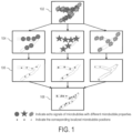
- Figure 1 illustrates the general idea of microbubble separation for super-resolution ultrasound microvessel imaging.
- the echo signals of micro bubbles with different properties such as spatiotemporal hemodynamic and acoustic properties are indicated with different marks and colors in FIG. 1 .
- Unit 102 indicates the conventional vessel image formed with overlapping echo signals of microbubbles, where the spatial resolution is physically limited by the wavelength of ultrasound.
- microbubbles are separated into different subsets with sparser populations (unit 104). And then processing is performed for each subset of microbubble signals separately to localize the positions of spatially isolated microbubbles and retrieve the super-resolved microvessel images, as indicated by unit 106.
- the subset microvessel images are then combined to generate the final super-resolved image with high microbubble concentration, as indicated by unit 1 08.
- the original microbubbles are only separated into 3 subsets in FIG. 1 .
- the number of subsets can be arbitrary.
- super-resolution refers to a resolution that is enhanced relative to the resolution attainable with the imaging system.
- super-resolution ultrasound images can refer to images with a resolution that is finer than the diffraction limit.
- the method includes accessing ultrasound data with a computer system, as indicated at step 202.
- accessing the ultrasound data with the computer system can include retrieving previously acquired ultrasound data from a memory or other data storage device or medium, which may be a part of or separate from the computer system.
- accessing the ultrasound data can include acquiring such data with an ultrasound system and communicating the acquired data to the computer system, which may be a part of or separate from the ultrasound system.
- the ultrasound data can be acquired using any suitable detection sequence, including line-by-line scanning, compounding plane wave imaging, synthetic aperture imaging, compounding diverging beam imaging, and so on.
- the ultrasound data can be ultrasound radiofrequency data, ultrasound in-phase quadrature ("IQ") data, ultrasound envelope data, or the like.
- the ultrasound data may be 1D data, 2D data, or 3D data.
- the ultrasound data contains one or more spatial dimensions, which may include a lateral dimension, an axial dimension, an elevational dimension, and combinations thereof.
- the ultrasound data can contain two spatial dimensions, such as the lateral and axial dimensions.
- the ultrasound data may also contain a temporal dimension, such as a dimension in slow time (i.e., the temporal direction along which multiple ultrasound signals are collected).
- the microbubble signal can be obtained from both the linear and nonlinear components of the ultrasound wave.
- data acquisition can be combined with either fundamental imaging or nonlinear imaging sequences.
- nonlinear imaging sequences include pulse inversion ("PI"), amplitude modulation (“AM”), and pulse inversion amplitude modulation (“PIAM”).
- PI pulse inversion
- AM amplitude modulation
- PIAM pulse inversion amplitude modulation
- the linear component is typically at the fundamental frequency of the applied ultrasound wave, while the nonlinear component can be at both the harmonic frequencies of the applied ultrasound wave, at the fundamental frequency of the applied ultrasound wave, at subharmonic frequencies, at ultraharmonic frequencies, or combinations thereof.
- the nonlinearity introduced by amplitude-modulation-base imaging methods can be at the fundamental frequency.
- Microbubble signal data are generated by extracting microbubble signals from the ultrasound data, as indicated at step 204.
- isolating the microbubbles signals includes isolating microbubble signals from the background signals, such as tissue signal and signals from non-changing microbubbles that do not change between acquisition frames (e.g., when a microbubble that does not move between frames).
- the microbubble signals can be isolated using frame-to-frame signal subtraction, tissue clutter filtering, and so on.
- Tissue clutter filtering techniques can include high-pass filtering along the temporal direction of the signal, singular value decomposition ("SVD")-based filtering, regression-based filtering, eigen-based filtering, and so on.
- SVD singular value decomposition
- temporal high-pass filtering can be used to isolate microbubble signals.
- a cutoff frequency that is lower than the temporal frequency of the isolated microbubble signal, but higher than that of background signal can be used to filter the ultrasound data to isolate microbubble signals.
- an SVD-based filtering can be used, in which a singular value cutoff can be used to separate the background signal (e.g., the tissue signal and nonmoving microbubble signal, which are typically projected to low-order singular values) from the isolated moving microbubble signals (which are typically projected to intermediate-to-high-order singular values).
- the block-wise adaptive SVD filter described in co-pending U.S. Patent Application No. 16/079,289 can be used to implement an SVD-based filtering to extract the microbubble signals.
- the accelerated SVD filter described in co-pending U.S. Patent Application No. 15/887, 029 can be used to implement an SVD-based filtering to extract the microbubble signals.
- the isolated microbubble signals in the microbubble signal data can be pre-processed, as indicated at step 206.
- this pre-processing may include denoising the microbubble signals. Removing the noise in each frame of the microbubble signal can help to more accurately localize and track the microbubbles.
- noise has similar features to microbubble signals, and it can be challenging to differentiate the two when the noise becomes stronger and the microbubble signal gets weaker in deeper regions of the tissue.
- noise signals can be falsely marked as microbubble signals, which results in inaccurate microbubble tracking and accumulation.
- denoising can be implemented using an intensity-based thresholding method. Such methods are more accurate when it can be assumed that the microbubble signals are stronger than the background noise signals. For example, by suppressing pixels with intensity values less than a selected value (e.g., -30 dB to the maximum intensity value in the current field-of-view), a significant amount of background noise can be suppressed.
- a selected value e.g., -30 dB to the maximum intensity value in the current field-of-view
- the microbubble signals can be denoised based at least in part on the spatiotemporal information contained in the microbubble signals. Because microbubbles move with blood flow, the microbubble movements are deterministic events that can be continuously tracked in multiple acquisition frames, while noise events are random and will not show any track-like features across multiple acquisition frames. These differences between microbubbles and noise can be exploited in the spatiotemporal domain for robust noise suppression. As an example, a non-local means (“NLM”) denoising filter can be applied to the original, noisy microbubble data.
- NLM non-local means
- Another advantage of the spatiotemporal denoising filter described above is that because the denoising is performed in the spatiotemporal domain, there is little to no spatial blurring of the underlying microbubble signal.
- Other denoising methods e.g., convolutional Gaussian smoothing, Gaussian spectral apodization, wavelet thresholding, or iterative total variation ("TV") minimization
- TV iterative total variation
- the axial-temporal microbubble signal data can be used for denoising, while in other implementations lateral-temporal data or full axial-lateral-temporal 3D data can also be used for denoising.
- noise suppression can be performed using any suitable denoising filter, including but not limited to any form of spatial-temporal low-pass filter, smooth filter, median filter, Savitzky-Golay filter, nonlocal mean filter, amplitude thresholding, and so on.
- An intensity equalization process can also be performed to equalize the spatial-dependent intensity of the microbubble signals due to the effect of time-gain compensation ("TGC"), tissue attenuation and beamforming process. Examples of such techniques, such as using a noise profile to equalize the microbubble signals, are described in U.S. Patent Application No. 16/079,289 .
- the microbubble signal data are separated into subsets of microbubble signal data, as indicated at step 208.
- the microbubble signal data are separated into subsets based on microbubble properties, characteristics, or both. In this way, each subset of microbubble signal data will have a sparser concentration than the original microbubble signal data.
- the microbubble signal data can be separated into subsets based on the spatial-temporal hemodynamic characteristics of microbubbles in the microbubble signal data.
- the microbubble signal data can be separated into subsets based on acoustic characteristics of microbubbles.
- the microbubble signal data can be separated into subsets by inputting the microbubble signal data to a suitably trained machine learning algorithm, or other artificial intelligence-based algorithms, generating output as subsets of separated microbubble signal data.
- a suitably trained machine learning algorithm or other artificial intelligence-based algorithms, generating output as subsets of separated microbubble signal data.
- super-resolution microvessel images are generated from each subset of microbubble signal data, as indicated generally at process block 210.
- This process can generally include removing tissue motion, microbubble localization, and microbubble tracking and accumulation.
- the super-resolution microvessel images can include microbubble density images, which can depict morphology of microvasculature; microbubble velocity images, including velocity amplitude and direction, which can depict the microbubble flowing speed distribution; and so on.
- Microbubbles are localized in each subset of microbubble signal data, as indicated at step 212.
- this process includes identifying locations in each time frame of the microbubble signal data at which microbubbles are located. For instance, the center location of each isolated microbubble signal is located, such that the movement of the microbubble can be tracked through time.
- the center location of the localized microbubbles can also be used to construct super-resolution microvessel images and to track the movement of the microbubbles to calculate hemodynamics measurements, such as blood flow speed.
- the microbubbles can be localized in the denoised microbubble signal data using deblurring and deconvolution methods, such as the CLEAN algorithm, sparsity or entropy-based iterative regression methods, a blind deconvolution method, and so forth.
- deblurring and deconvolution methods such as the CLEAN algorithm, sparsity or entropy-based iterative regression methods, a blind deconvolution method, and so forth.
- the microbubbles can be localized based on a two-dimensional normalized cross-correlation-based method that focuses on detecting structures with good correlation to the point-spread-function ("PSF") of the ultrasound system used to acquire the microbubble signal data, as described in co-pending Patent Application No. 16/617,628 .
- PSF point-spread-function
- tissue motion can optionally be removed from the microvessel images, as indicated at step 214.
- image registration can be performed to remove tissue motion to avoid blurring in the microvessel images.
- Image registration can be performed based on motion estimations from the original acquired ultrasound data, or on the microbubble signal data. Any suitable image registration algorithm can be applied, including but not limited to global or local cross-correlation methods, global or local phase-correlation based methods, global or local optical flow methods, and so on.
- microbubble tracking process can also provide a quality control step for the microbubble localization step. For instance, microbubble tracking can be used to reject false microbubble localizations from noise or unreliable microbubbles signals by removing localized microbubbles that cannot be tracked for a certain amount of time.
- microbubble tracking can be implemented by locally tracking a single microbubble's movement.
- a global microbubble tracking method can be implemented. Examples of microbubble tracking techniques that can be implemented include local and global tracking methods, such as those described in co-pending Patent Application No. 16/617,628 .
- microvessel images are produced for each subset of microbubble signal data based on the localization and tracking results for that subset, as indicated at step 218. Because the microvessel images are generated from subsets of data in which microbubbles signals have been separated into sparser data sets, the microvessel images will also each be representative of a sparser microbubble density.
- the microvessel images can include accumulated microbubble location maps throughout all of the acquisition frames.
- the microvessel images can include blood flow speed maps with blood speed values assigned to all the locations at which microbubbles were detected.
- An accumulated microbubble location map depicts the number of times that a microbubble appeared at a certain location. Typically, larger vessels have more microbubbles flow through them during a given time interval, and thus will appear brighter than smaller vessels, which have fewer microbubbles flowing through them within the same time interval.
- microvessel images generated for each subset are then combined to generate a microvessel image representative of a higher microbubble density, as indicated at step 220.
- a microvessel image representative of a higher microbubble density As indicated at step 220.
- the microvessel images from each subset can be combined using any suitable method, such as averaging or weighted averaging.
- the combination of micro vessel velocity images from different subsets of data can be in any appropriate form, such as taking the mean, densityweighted average (average weighted by the density image), median of the subset velocity images, and so on, to generate the final microvessel velocity image.
- the microvessel images (e.g., the combined microvessel image(s), the subset microvessel images, or both) can be displayed to a user or stored for later use, such as for later analysis, as indicated at step 222.
- microvascular morphology measurements e.g., vessel density and vessel tortuosity
- microvessel hemodynamics measurements e.g., blood flow speed and blood flow volume
- the microvessel images can be superimposed, or presented side-by-side, with B-mode images of the targeted tissue.
- microvessel blood flow speed images with color-encoded flow direction can also be superimposed, or presented side-by-side, with B-mode images of the targeted tissue.
- a multi-flow-direction color hue can be used to indicate more than two directions of flow.
- other derived measurements such as other morphological measurements or hemodynamic measurements, can be estimated from the microvessel images and displayed to a user or stored for later use. For instance, other morphological measurements, hemodynamic measurements, or both, can be estimated based on microbubble density and/or microbubble velocity images. Maps of these estimated measurements can be generated, or individual measurements can be estimated and stored.
- Vessel density can be calculated by selecting a region-of-interest on the combined microvessel image or images, from which the vessel density can be calculated by the total area (or total volume as in 3D imaging) of the vessel signal divided by the total area (or volume) of the region-of-interest.
- Vessel tortuosity can be measured by methods such as the distance metric, which provides a ratio of the actual path length of vessels normalized by linear distance between the vessel curve endpoints.
- the microvessel blood flow speed from the entire region-of-interest can be averaged to represent the perfusion index, or the blood flow speed can be integrated by the total cross-sectional area of the microvessel within the region-of-interest to derive a cross-sectional blood flow volume rate that can represent the perfusion index, or the blood flow speed from all microvessels can be used to generate a histogram (e.g., with x-axis representing blood flow speed and y-axis representing the total number of pixels with a certain blood flow speed in each x-axis bin) to represent the perfusion index.
- a histogram e.g., with x-axis representing blood flow speed and y-axis representing the total number of pixels with a certain blood flow speed in each x-axis bin
- the combined super-resolution microvessel image or images can also be displayed as dynamic video clips that show the dynamic microbubble movement to present the process of perfusion of a certain microvasculature.
- the movement of the microbubbles which provides information of perfusion, can be monitored over time using such an approach.
- Another aspect of displaying a dynamic video clip is to use a different number of microbubble image frames to accumulate for different levels of microvessel details that can be dynamically displayed. For example, the more frames that are accumulated, the more microbubble movement tracks that can be visualized at a certain time instant. A high frame accumulation can be used to visualize slower flow vessels, and a low frame accumulation can be used to visualize faster flow vessels. Thus, by selectively choosing the number of frames to accumulate for a display, different blood flow speeds can be depicted and displayed to the user.
- the flowchart illustrated in FIG. 2 provides the general steps of performing super-resolution microvessel imaging based on microbubble separation. Some of the steps can be optional, additional steps may be inserted, and the order of the steps can be appropriately adjusted. For instance, microbubble signal extraction may be omitted for specific imaging sequences, such as nonlinear contrast imaging, where the tissue clutter has already been suppressed from the acquired ultrasound data. In another example, the pre-processing may be omitted or partially omitted for those microbubble data with high signal-to-noise ratio ("SNR"). In yet another example, tissue motion removal may be omitted for those data with little or without tissue motion. Likewise, the tissue motion removal can be performed on the ultrasound data or the microbubble signal data.
- SNR signal-to-noise ratio
- microbubble signal data can be separated into different subsets of data based on properties or characteristics of the microbubbles.
- microbubble signals can be separated based on the differences of spatiotemporal hemodynamics among microbubbles. For instance, different microbubbles in an image may have different movement speeds and directions, or their signals may de-correlate differently. By taking advantage of these microbubble hemodynamic differences, microbubble signals that may otherwise spatially or temporally overlap can be reliably separated from each other. In general, any processing algorithm that can distinguish microbubble signals with different moving speeds/directions and separate them into different subsets can be applied here.
- microbubbles with different moving velocities can be separated using eigen-based filtering, including but not limited to singular value decomposition ("SVD”) filtering, principal component analysis ("PCA”), or other eigenvalue-based decompositions.
- SVD filtering singular value decomposition
- PCA principal component analysis
- microbubbles with different spatiotemporal coherence can be associated with different components, eigenvalues, or so on.
- the method includes accessing microbubble signal data with a computer system, as indicated at step 302.
- the microbubble signal data can be accessed by retrieving such data from a memory or other data storage device or medium.
- the microbubble signal data can be accessed after they are generated by the computer system as described above.
- a singular value decomposition is then performed on the microbubble signal data, as indicated at step 304.
- the microbubble signal data are input to an SVD filter, generating output as singular value data, which may include singular values, a singular value curve, or combinations thereof.
- tissue signals are typically represented by the low-order singular values
- slow-moving microbubble signals are typically represented by low-to-medium-order singular values
- fast-moving microbubble signals are typically represented by medium-to-high-order singular values.
- the singular value data are therefore divided or otherwise separated into segments, as indicated at step 306.
- the singular value data can be separated into segments by selecting a range of singular values for each segment, or by equally or non-equally dividing the singular value data into the segments.
- An inverse SVD is then applied to the segments of singular value data in order to reconstruct subsets of microbubble data, as indicated at step 308.
- the original data are divided into several subsets.
- the number of segments can be arbitrary. Overlaps between segments of the singular value curve, and a smooth transition between adjacent segments, can be used in some implementations to improve the reconstruction of the subsets of microbubble signal data.
- Each subset of data corresponds to a specific segment of singular value curve, which contains microbubble signals with certain coherence/velocity ranges associated with the singular value segment. This SVD filtering can be performed on the extracted microbubble signal data, or on the original acquired ultrasound data.
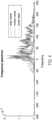
- the microbubble signal data can be separated using temporal filtering, based on the hypothesis that microbubbles with different velocities correspond to different Doppler frequency components (i.e., frequency components in temporal direction).
- the Doppler frequency is typically estimated as the frequency of blood flow or microbubble signals along the temporal dimension (which may also be referred to as the slow-time dimension).
- the amount of Doppler frequency shift is proportional to microbubble moving velocity along the axial direction (i.e. along the ultrasound beam direction).
- frequency spectrums of microbubble ultrasound signals from three different size vessels with different flow speeds are plotted in FIG. 4 , which roughly reveals the association between Doppler frequency shift and flow velocity: the higher the flowing speed, the larger the Doppler frequency shift is.
- appropriate temporal filters e.g., low-pass filters, band-pass filters, high-pass filters
- different Doppler frequency components can be separated.
- the original microbubble signal data can be separated into multiple subsets of data each corresponding to a different Doppler frequency band.
- the number of subsets of data i.e., the number of frequency bands
- the number of subsets of data can be arbitrary.
- Different Doppler frequency bands can have overlaps, and smooth transitions between stopbands and passbands for each filter can be beneficial for signal reconstruction.
- Any suitable type of filter can be applied, including but not limited to infinite impulse response (“IIR”) and finite impulse response (“FIR”) filters.
- IIR infinite impulse response
- FIR finite impulse response
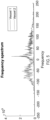
- the microbubble signal data can be separated using temporal-based directional filtering, based on the hypothesis that positive and negative Doppler frequency components correspond to microbubbles moving toward and away from the transducer, respectively. Therefore, this method is also based on the difference of Doppler frequency shift to separate microbubbles moving with different directions.
- the positive Doppler frequency components of the blood flow or microbubble signals correspond to the flow moving towards the transducer (upwards), and the negative Doppler frequency components represent the flows moving away from the probe (downwards).
- FIG. 5 shows example Doppler frequency spectra of microbubble signals moving in opposite directions, where the positive or negative components are dominant for the two Doppler signals, respectively.
- a Fourier transform can be used to calculate the frequency spectrum along the temporal direction of the microbubble signal, and then positive and negative halves of the spectrum can be split. After the spectra are split, inverse Fourier transforms can be performed to retrieve the two subsets of data. Smooth transitions between frequency bands in the frequency domain can be applied to avoid signal blurring in the time domain.
- This separation operation is a process of temporal filtering, and thus any type of filters that can separate the data into positive and/or negative components can be applied to perform the microbubble separation.
- the filter can be in any suitable form, including but not limited to IIR and FIR filters.
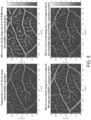
- microbubble signals can be separated using spatial-temporal based filtering, based on the hypothesis that microbubbles with different velocity and moving directions may occupy different quadrants (subspaces) of the Fourier spectrum of spatial-temporal microbubble data.
- a spatial-temporal filter is applied to isolate the microbubbles moving in different directions and velocity.
- the spatial-temporal ( x,y,t ) microbubble signal data can be converted to the spatial frequency-temporal frequency domain ( k x ,k y ,f t ) or the wavenumber-frequency domain (k-f) by using a 3D Fourier transform.
- the components in the wavenumber domain represent the direction and velocity information of the flows, and thus filters can be designed on the wavenumber-frequency domain to preserve certain angular and velocity components and suppress the rest.
- FIG. 6 shows the filter response for separating bubbles in four different directions.
- the edge (transition) of the directional filter can be smoothed to minimize the blurring effect of the filtered microbubble signals using any kind of window functions or filters.
- a band-pass filter can still be imposed on the directional filter response in the radial direction to suppress the high or low spatial frequency components in the k-f domain in order to suppress unwanted motion components.
- Microbubbles moving within the angular range near the primary direction can be preserved for each directional filter, and microbubbles moving in other directions will be suppressed.
- the velocity range can also be combined into the directional filter design by considering the f t domain, to separate bubbles with different motion directions and velocity ranges.
- Any suitable filter operating on the 3D k-f domain can be applied.
- a set of 3D cone-shaped filters in the k-f domain can be used to separate microbubble signals with different directions and speeds into subsets of data.
- a relatively large passband for each 3-D filter with smooth transitions and large overlaps between adjacent filters may be applied to minimize MB signal distortion. Therefore, by applying these multi-directional and multi-velocity filters, the original microbubble populations can be separated into multiple subsets with sparser populations. Again, the number of directions and velocity ranges for bubble separation can be arbitrary.
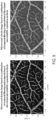
- FIGS. 7 and 8 show examples of super-resolution microvessel density images and microvessel velocity images, respectively, based on ultrasound data acquired from a chick embryo chorioallantoic membrane (CAM).
- the images shown in FIGS. 7 and 8 were generated from the original data without bubble separation; using SVD filtering to generate nine subsets of microbubble signals data, from which images were generated and combined; using the temporal filter based microbubble separation method, which shows much more subtle microvasculature that cannot be resolved by original microvessel images without bubble separation; and using the temporal-based directional microbubble separation method.
- the microvasculature can be better resolved using the microbubble separation methods because in these instances a larger number of microbubbles are detected that otherwise would not have been detected without the microbubble separation techniques.
- microbubble separation techniques described above can be used separately or in combination with each other to separate microbubble signal data into subsets. Any combination between methods can be applied.
- SVD-based filtering can be combined with temporal filtering to further separate microbubble signal data from each singular value segments into multiple frequency bands.
- temporal filtering can be combined with the temporal-based directional method to further separate each frequency band into positive and negative halves.
- SVD-based filtering can be combined with the temporal-based directional method to further separate microbubble data from each singular value segment into positive and negative Doppler frequency components.
- all the above methods can be combined together to perform microbubble separation.
- FIG. 9 shows a super-resolution microvessel density image and a microvessel velocity image obtained with the combination of temporal filtering and temporal-based directional microbubble separation methods. Further improvement in microvasculature reconstruction and blood flow speed estimation can be observed as compared with the microvessel images derived with either one of the two methods individually.
- FIG. 10 shows another super-resolution microvessel image from a chick embryo brain, showing the significant improvement that can be achieved with the combination of temporal filtering and temporal-based directional microbubble separation methods.
- microbubble signal data can in some instances be separated into different subsets of data based on properties or characteristics of the microbubbles using artificial intelligence ("AI") based techniques.
- AI artificial intelligence
- the microbubble signal data can be input into an appropriately trained machine learning algorithm, generating output as subsets of separated microbubble signal data.
- Microbubble signal data can be separated based on properties or characteristics, such as any hemodynamic (e.g., moving velocity, direction, and so on) or acoustical property (e.g., intensities, blinking behaviors, frequency response to the sonifying ultrasound waves, and so on) that can distinguish microbubble signal from each other.
- Al-based methods that can exploit the characteristics of microbubble signals can be used to perform the classification, isolation, and/or separation of the microbubble signal data into subsets of data.
- any suitable algorithm can be applied, including but not limited to feature learning, deep learning, sparse dictionary learning, and so on.
- the machine learning algorithms can be supervised, semisupervised, or unsupervised.
- any suitable algorithm can be beneficially applied for the purpose of microbubble separation, such as convolution neural network (“CNN”), deep neural network (“DNN”), feedforward neural network (“FNN”), deep Boltzmann network (“DBN”), and so on.
- Al-based methods such as machine learning, typically involve a large amount of representative data, with or without specific labels, to serve as a training set to train the algorithm.
- the more data being used to train the machine learning algorithm the more accurate the algorithm can be. Therefore, the generation of training data is an important consideration when constructing a machine learning algorithm for a specific task.
- computational simulations, phantom experiments, or both can be used to generate microbubble data as a training set, which can then be used to train a suitable AI algorithm, such as a machine learning algorithm.
- the ultrasound signals of microbubbles with different characteristics such as concentrations, hemodynamics (e.g., moving velocity, direction) and acoustical properties (e.g., intensities, blinking behaviors, and frequency response to the sonifying ultrasound waves) can be simulated.
- the point spread function ("PSF") of the ultrasound image in the computational simulation can be varied according to practical imaging situations.
- the PSF can be experimentally measured or can be approximated using a Gaussian model or other suitable models.
- the initial spatial locations and the backscattering intensity of the microbubbles can be randomized, and background noise can be added to mimic the true microbubble imaging scenarios.
- These simulated microbubble data can be labeled with different properties or characteristics and allocated into different subsets, and serve as the training data for machine learning algorithms.
- the training microbubble data can be obtained from any type of flow phantom, flow channel, water tank, or in vivo vessel using certain ultrasound systems with injections of microbubbles.
- Ultrasound data acquisition can be performed under various imaging and experimental settings, such as different microbubble concentrations, flowing velocities and directions, different acoustic transmission and SNR situations, and so on.
- the training data can be labeled as different microbubble characteristics or different subsets, and can be used to train a suitable AI algorithm. Then, the trained algorithms can be applied to perform microbubble separation on the target microbubble data to separate them into subsets with sparser microbubble concentrations.
- One or more neural networks are trained on the training data.
- the neural network can be trained by optimizing network parameters (e.g., weights, biases, or both) based on minimizing a loss function.
- the loss function may be a mean squared error loss function.
- Training a neural network may include initializing the neural network, such as by computing, estimating, or otherwise selecting initial network parameters (e.g., weights, biases, or both). Training data can then be input to the initialized neural network, generating output as separated subsets of microbubble signal data. The quality of the output data can then be evaluated, such as by passing the output data to the loss function to compute an error. The current neural network can then be updated based on the calculated error (e.g., using back-propagation methods based on the calculated error). For instance, the current neural network can be updated by updating the network parameters (e.g., weights, biases, or both) in order to minimize the loss according to the loss function. When the error has been minimized (e.g., by determining whether an error threshold or other stopping criterion has been satisfied), the current neural network and its associated network parameters represent the trained neural network.
- initial network parameters e.g., weights, biases, or both.
- FIG. 11 a flowchart is illustrated as setting forth the steps of an example method for separating microbubble signal data into different subsets of data based on properties or characteristics of the microbubbles using a suitably trained neural network or other machine learning algorithm.
- the method includes accessing microbubble signal data with a computer system, as indicated at step 1102.
- Accessing the microbubble signal data may include retrieving such data from a memory or other suitable data storage device or medium.
- accessing the microbubble signal data may include acquiring or otherwise generating such data with an ultrasound system, as described above, and transferring or otherwise communicating the data to the computer system, which may be a part of the ultrasound system.
- a trained neural network (or other suitable machine learning algorithm) is then accessed with the computer system, as indicated at step 1104.
- Accessing the trained neural network may include accessing network parameters (e.g., weights, biases, or both) that have been optimized or otherwise estimated by training the neural network on training data.
- retrieving the neural network can also include retrieving, constructing, or otherwise accessing the particular neural network architecture to be implemented. For instance, data pertaining to the layers in the neural network architecture (e.g., number of layers, type of layers, ordering of layers, connections between layers, hyperparameters for layers) may be retrieved, selected, constructed, or otherwise accessed.
- the neural network is trained, or has been trained, on training data in order to separate microbubble signal data into subsets of data based on properties or characteristics of the microbubbles.
- the properties or characteristics of the microbubbles are then input to the one or more trained neural networks, generating output as separated subsets of data, as indicated at step 1106.
- the output data generated by inputting the microbubble signal data to the trained neural network(s) can then be displayed to a user, stored for later use or further processing, or both, as indicated at step 1108, and described above in more detail.
- the separated subsets of data can be further processed to generate super-resolution images, as described above.
- FIG. 12 illustrates an example of an ultrasound system 1200 that can implement the methods described in the present disclosure.
- the ultrasound system 1200 includes a transducer array 1202 that includes a plurality of separately driven transducer elements 1204.
- the transducer array 1202 can include any suitable ultrasound transducer array, including linear arrays, curved arrays, phased arrays, and so on.
- each transducer element 1202 When energized by a transmitter 1206, each transducer element 1202 produces a burst of ultrasonic energy.
- the ultrasonic energy reflected back to the transducer array 1202 from the object or subject under study e.g., an echo
- an electrical signal e.g., an echo signal
- the transmitter 1206, receiver 1208, and switches 1210 are operated under the control of a controller 1212, which may include one or more processors.
- the controller 1212 can include a computer system.
- the transmitter 1206 can transmit unfocused or focused ultrasound waves. In some configurations, the transmitter 1206 can also be programmed to transmit diverged waves, spherical waves, cylindrical waves, plane waves, or combinations thereof. Furthermore, the transmitter 1206 can be programmed to transmit spatially or temporally encoded pulses.
- the receiver 1208 can be programmed to implement a suitable detection sequence for the imaging task at hand.
- the detection sequence can include one or more of lifie-by-line scanning, compounding plane wave imaging, synthetic aperture imaging, and compounding diverging beam imaging.
- the transmitter 1206 and the receiver 1208 can be programmed to implement a high frame rate.
- a frame rate associated with an acquisition pulse repetition frequency ("PRF") of at least 100 Hz can be implemented.
- PRF acquisition pulse repetition frequency
- the ultrasound system 1200 can sample and store at least one hundred ensembles of echo signals in the temporal direction.
- the controller 1212 can be programmed to design an imaging sequence using the techniques described in the present disclosure, or as otherwise known in the art. In some embodiments, the controller 1212 receives user inputs defining various factors used in the design of the imaging sequence.
- a scan can be performed by setting the switches 1210 to their transmit position, thereby directing the transmitter 1206 to be turned on momentarily to energize each transducer element 1204 during a single transmission event according to the designed imaging sequence.
- the switches 1210 can then be set to their receive position and the subsequent echo signals produced by each transducer element 1204 in response to one or more detected echoes are measured and applied to the receiver 1208.
- the separate echo signals from each transducer element 1204 can be combined in the receiver 1208 to produce a single echo signal. Images produced from the echo signals can be displayed on a display system 1214.
- the receiver 1208 may include a processing unit, which may be implemented by a hardware processor and memory, to process echo signals or images generated from echo signals.
- a processing unit can isolate microbubble signals to produce microbubble signal data, localize microbubbles in microbubble signal data, track microbubble locations through time frames, accumulate microbubble locations, and produce microvessel images using the methods described in the present disclosure.
- a computing device 1350 can receive one or more types of data (e.g., ultrasound data, microbubble signal data) from image source 1302, which may be an ultrasound image source.
- image source 1302 which may be an ultrasound image source.
- computing device 1350 can execute at least a portion of a microvessel image generating system 1304 to separate microbubble signal data into subsets of data, generate microvessel images from those subsets of data, and generate a combined microvessel image by combining the microvessel images generated from the subsets of data.
- the computing device 1350 can communicate information about data received from the image source 1302 to a server 1352 over a communication network 1354, which can execute at least a portion of the microvessel image generating system 1304.
- the server 1352 can return information to the computing device 1350 (and/or any other suitable computing device) indicative of an output of the microvessel image generating system 1304.
- computing device 1350 and/or server 1352 can be any suitable computing device or combination of devices, such as a desktop computer, a laptop computer, a smartphone, a tablet computer, a wearable computer, a server computer, a virtual machine being executed by a physical computing device, and so on.
- the computing device 1350 and/or server 1352 can also reconstruct images from the data.
- image source 1302 can be any suitable source of image data (e.g., measurement data, images reconstructed from measurement data), such as an ultrasound system, another computing device (e.g., a server storing image data), and so on.
- image source 1302 can be local to computing device 1350.
- image source 1302 can be incorporated with computing device 1350 (e.g., computing device 1350 can be configured as part of a device for capturing, scanning, and/or storing images).
- image source 1302 can be connected to computing device 1350 by a cable, a direct wireless link, and so on.
- image source 1302 can be located locally and/or remotely from computing device 1350, and can communicate data to computing device 1350 (and/or server 1352) via a communication network (e.g., communication network 1354).
- a communication network e.g., communication network 1354
- communication network 1354 can be any suitable communication network or combination of communication networks.
- communication network 1354 can include a Wi-Fi network (which can include one or more wireless routers, one or more switches, etc.), a peer-to-peer network (e.g., a Bluetooth network), a cellular network (e.g., a 3G network, a 4G network, etc., complying with any suitable standard, such as CDMA, GSM, LTE, LTE Advanced, WiMAX, etc.), a wired network, and so on.
- Wi-Fi network which can include one or more wireless routers, one or more switches, etc.
- peer-to-peer network e.g., a Bluetooth network
- a cellular network e.g., a 3G network, a 4G network, etc., complying with any suitable standard, such as CDMA, GSM, LTE, LTE Advanced, WiMAX, etc.
- communication network 1354 can be a local area network, a wide area network, a public network (e.g., the Internet), a private or semi-private network (e.g., a corporate or university intranet), any other suitable type of network, or any suitable combination of networks.
- Communications links shown in FIG. 13 can each be any suitable communications link or combination of communications links, such as wired links, fiber optic links, Wi-Fi links, Bluetooth links, cellular links, and so on.
- computing device 1350 can include a processor 1402, a display 1404, one or more inputs 1406, one or more communication systems 1408, and/or memory 1410.
- processor 1402 can be any suitable hardware processor or combination of processors, such as a central processing unit (“CPU"), a graphics processing unit (“GPU"), and so on.
- display 1404 can include any suitable display devices, such as a computer monitor, a touchscreen, a television, and so on.
- inputs 1406 can include any suitable input devices and/or sensors that can be used to receive user input, such as a keyboard, a mouse, a touchscreen, a microphone, and so on.
- communications systems 1408 can include any suitable hardware, firmware, and/or software for communicating information over communication network 1354 and/or any other suitable communication networks.
- communications systems 1408 can include one or more transceivers, one or more communication chips and/or chip sets, and so on.
- communications systems 1408 can include hardware, firmware and/or software that can be used to establish a Wi-Fi connection, a Bluetooth connection, a cellular connection, an Ethernet connection, and so on.
- memory 1410 can include any suitable storage device or devices that can be used to store instructions, values, data, or the like, that can be used, for example, by processor 1402 to present content using display 1404, to communicate with server 1352 via communications system(s) 1408, and so on.
- Memory 1410 can include any suitable volatile memory, non-volatile memory, storage, or any suitable combination thereof.
- memory 1410 can include RAM, ROM, EEPROM, one or more flash drives, one or more hard disks, one or more solid state drives, one or more optical drives, and so on.
- memory 1410 can have encoded thereon, or otherwise stored therein, a computer program for controlling operation of computing device 1350.
- processor 1402 can execute at least a portion of the computer program to present content (e.g., images, user interfaces, graphics, tables), receive content from server 1352, transmit information to server 1352, and so on.
- server 1352 can include a processor 1412, a display 1414, one or more inputs 1416, one or more communications systems 1418, and/or memory 1420.
- processor 1412 can be any suitable hardware processor or combination of processors, such as a CPU, a GPU, and so on.
- display 1414 can include any suitable display devices, such as a computer monitor, a touchscreen, a television, and so on.
- inputs 1416 can include any suitable input devices and/or sensors that can be used to receive user input, such as a keyboard, a mouse, a touchscreen, a microphone, and so on.
- communications systems 1418 can include any suitable hardware, firmware, and/or software for communicating information over communication network 1354 and/or any other suitable communication networks.
- communications systems 1418 can include one or more transceivers, one or more communication chips and/or chip sets, and so on.
- communications systems 1418 can include hardware, firmware and/or software that can be used to establish a Wi-Fi connection, a Bluetooth connection, a cellular connection, an Ethernet connection, and so on.
- memory 1420 can include any suitable storage device or devices that can be used to store instructions, values, data, or the like, that can be used, for example, by processor 1412 to present content using display 1414, to communicate with one or more computing devices 1350, and so on.
- Memory 1420 can include any suitable volatile memory, non-volatile memory, storage, or any suitable combination thereof.
- memory 1420 can include RAM, ROM, EEPROM, one or more flash drives, one or more hard disks, one or more solid state drives, one or more optical drives, and so on.
- memory 1420 can have encoded thereon a server program for controlling operation of server 1352.
- processor 1412 can execute at least a portion of the server program to transmit information and/or content (e.g., data, images, a user interface) to one or more computing devices 1350, receive information and/or content from one or more computing devices 1350, receive instructions from one or more devices (e.g., a personal computer, a laptop computer, a tablet computer, a smartphone), and so on.
- information and/or content e.g., data, images, a user interface
- processor 1412 can execute at least a portion of the server program to transmit information and/or content (e.g., data, images, a user interface) to one or more computing devices 1350, receive information and/or content from one or more computing devices 1350, receive instructions from one or more devices (e.g., a personal computer, a laptop computer, a tablet computer, a smartphone), and so on.
- image source 1302 can include a processor 1422, one or more image acquisition systems 1424, one or more communications systems 1426, and/or memory 1428.
- processor 1422 can be any suitable hardware processor or combination of processors, such as a CPU, a GPU, and so on.
- the one or more image acquisition systems 1424 are generally configured to acquire data, images, or both, and can include an ultrasound system. Additionally or alternatively, in some embodiments, one or more image acquisition systems 1424 can include any suitable hardware, firmware, and/or software for coupling to and/or controlling operations of an ultrasound system. In some embodiments, one or more portions of the one or more image acquisition systems 1424 can be removable and/or replaceable.
- image source 1302 can include any suitable inputs and/or outputs.
- image source 1302 can include input devices and/or sensors that can be used to receive user input, such as a keyboard, a mouse, a touchscreen, a microphone, a trackpad, a trackball, and so on.
- image source 1302 can include any suitable display devices, such as a computer monitor, a touchscreen, a television, etc., one or more speakers, and so on.
- communications systems 1426 can include any suitable hardware, firmware, and/or software for communicating information to computing device 1350 (and, in some embodiments, over communication network 1354 and/or any other suitable communication networks).
- communications systems 1426 can include one or more transceivers, one or more communication chips and/or chip sets, and so on.
- communications systems 1426 can include hardware, firmware and/or software that can be used to establish a wired connection using any suitable port and/or communication standard (e.g., VGA, DVI video, USB, RS-232, etc.), Wi-Fi connection, a Bluetooth connection, a cellular connection, an Ethernet connection, and so on.
- memory 1428 can include any suitable storage device or devices that can be used to store instructions, values, data, or the like, that can be used, for example, by processor 1422 to control the one or more image acquisition systems 1424, and/or receive data from the one or more image acquisition systems 1424; to images from data; present content (e.g., images, a user interface) using a display; communicate with one or more computing devices 1350; and so on.
- Memory 1428 can include any suitable volatile memory, non-volatile memory, storage, or any suitable combination thereof.
- memory 1428 can include RAM, ROM, EEPROM, one or more flash drives, one or more hard disks, one or more solid state drives, one or more optical drives, and so on.
- memory 1428 can have encoded thereon, or otherwise stored therein, a program for controlling operation of image source 1302.
- processor 1422 can execute at least a portion of the program to generate images, transmit information and/or content (e.g., data, images) to one or more computing devices 1350, receive information and/or content from one or more computing devices 1350, receive instructions from one or more devices (e.g., a personal computer, a laptop computer, a tablet computer, a smartphone, etc.), and so on.
- any suitable computer readable media can be used for storing instructions for performing the functions and/or processes described herein.
- computer readable media can be transitory or non-transitory.
- non-transitory computer readable media can include media such as magnetic media (e.g., hard disks, floppy disks), optical media (e.g., compact discs, digital video discs, Blu-ray discs), semiconductor media (e.g., random access memory (“RAM”), flash memory, electrically programmable read only memory (“EPROM”), electrically erasable programmable read only memory (“EEPROM”)), any suitable media that is not fleeting or devoid of any semblance of permanence during transmission, and/or any suitable tangible media.
- RAM random access memory
- EPROM electrically programmable read only memory
- EEPROM electrically erasable programmable read only memory
- transitory computer readable media can include signals on networks, in wires, conductors, optical fibers, circuits, or any suitable media that is fleeting and devoid of any semblance of permanence during transmission, and/or any suitable intangible media.
Landscapes
- Health & Medical Sciences (AREA)
- Life Sciences & Earth Sciences (AREA)
- Engineering & Computer Science (AREA)
- Physics & Mathematics (AREA)
- Medical Informatics (AREA)
- Radiology & Medical Imaging (AREA)
- Nuclear Medicine, Radiotherapy & Molecular Imaging (AREA)
- General Health & Medical Sciences (AREA)
- Biophysics (AREA)
- Molecular Biology (AREA)
- Veterinary Medicine (AREA)
- Public Health (AREA)
- Animal Behavior & Ethology (AREA)
- Surgery (AREA)
- Heart & Thoracic Surgery (AREA)
- Pathology (AREA)
- Biomedical Technology (AREA)
- Computer Vision & Pattern Recognition (AREA)
- General Physics & Mathematics (AREA)
- Radar, Positioning & Navigation (AREA)
- Remote Sensing (AREA)
- Computer Networks & Wireless Communication (AREA)
- Hematology (AREA)
- Vascular Medicine (AREA)
- Theoretical Computer Science (AREA)
- Acoustics & Sound (AREA)
- Nonlinear Science (AREA)
- Multimedia (AREA)
- Physiology (AREA)
- Quality & Reliability (AREA)
- Ultra Sonic Daignosis Equipment (AREA)
Claims (20)
- Verfahren zur Erzeugung eines Bildes der Mikrovaskulatur in einem Individuum aus Ultraschalldaten, wobei das Verfahren umfasst:(a) Zugreifen auf (202) Ultraschalldaten, die von einem Individuum aufgenommen wurden, mittels eines Computersystems;(b) Erzeugen von Mikroblasen-Signaldaten durch Extrahieren (204) von Mikroblasen-Signalen aus den Ultraschalldaten unter Verwendung des Computersystems;(c) Erzeugen einer Vielzahl von Teilmengen von Mikroblasen-Signaldaten aus den Mikroblasen-Signaldaten unter Verwendung des Computersystems, wobei die Vielzahl von Teilmengen von Mikroblasen-Signaldaten durch Zerlegen (208) der Mikroblasen-Signaldaten in Teilmengen von Mikroblasen-Signalen basierend auf akustischen Eigenschaften einzelner Mikroblasen erzeugt wird;(d) Erzeugen (218) eines Mikrogefäßbildes für jede Teilmenge von Mikroblasen-Signaldaten unter Verwendung des Computersystems, wobei jedes Mikrogefäßbild eine dünnbesetzte Teilmenge von Mikroblasensignalen darstellt; und(e) Erzeugen (220) eines kombinierten Mikrogefäßbildes auf der Grundlage einer Kombination des Mikrogefäßbildes für jede der Vielzahl von Untermengen von Mikroblasen-Signaldaten.
- Verfahren nach Anspruch 1, wobei die mehreren Teilmengen von Mikroblasen-Signaldaten zudem basierend auf der räumlich-zeitlichen Hämodynamik von Mikroblasen zerlegt werden.
- Verfahren nach Anspruch 2, wobei die mehreren Teilmengen von Mikroblasen-Signaldaten auf der Grundlage einer Matrixzerlegung der Mikroblasen-Signaldaten oder einer Hauptkomponentenanalyse erzeugt werden.
- Verfahren nach Anspruch 3, wobei die Matrixzerlegung entweder eine Singulärwertzerlegung (304) oder eine Eigenwertzerlegung ist.
- Verfahren nach Anspruch 4, wobei es sich bei der Matrixzerlegung um die Singulärwertzerlegung handelt und jede der mehreren Teilmengen von Mikroblasen-Signaldaten durch Zerlegung von Mikroblasen-Signaldaten in Teilmengen erzeugt wird, die jeweils einem anderen Bereich von Singulärwerten zugeordnet sind, der aus der Singulärwertzerlegung der Mikroblasen-Signaldaten bestimmt wird.
- Verfahren nach Anspruch 5, wobei mindestens ein zeitlicher Filter auf jede Teilmenge von Mikroblasen-Signaldaten angewendet wird, um Mikroblasen-Signale ferner in zusätzliche Teilmengen basierend auf unterschiedlichen Doppler-Frequenzbändern in jeder Teilmenge von Mikroblasen-Signaldaten zu zerlegen.
- Verfahren nach Anspruch 5, wobei die mehreren Teilmengen von Mikroblasen-Signaldaten ferner durch Berechnung von Doppler-Frequenzkomponenten jeder Teilmenge von Mikroblasen-Signaldaten zerlegt werden, um positive und negative Doppler-Frequenzkomponenten in jeder Teilmenge von Mikroblasen-Signaldaten zudem in zwei zusätzliche Teilmengen von Mikroblasen-Signaldaten zu zerlegen.
- Verfahren nach Anspruch 2, wobei die mehreren Teilmengen von Mikroblasen-Signaldaten durch Anwenden mindestens eines zeitlichen Filters auf die Mikroblasen-Signaldaten erzeugt werden, um die Mikroblasen-Signaldaten in die mehreren Teilmengen von Mikroblasen-Signaldaten zu zerlegen, die jeweils einem anderen Doppler-Frequenzband entsprechen.
- Verfahren nach Anspruch 8, wobei die mehreren Teilmengen von Mikroblasen-Signaldaten ferner durch Berechnen von Doppler-Frequenzkomponenten jeder Teilmenge von Mikroblasen-Signaldaten zerlegt werden, um positive und negative Doppler-Frequenzkomponenten in jeder Teilmenge von Mikroblasen-Signaldaten zudem in zwei zusätzliche Teilmengen von Mikroblasen-Signaldaten zu zerlegen.
- Verfahren nach Anspruch 2, wobei die mehreren Teilmengen von Mikroblasen-Signaldaten durch Berechnen von Dopplerfrequenzkomponenten der Mikroblasen-Signaldaten und Zerlegen von positiven und negativen Dopplerfrequenzkomponenten in zwei Teilmengen von Mikroblasen-Signaldaten erzeugt werden.
- Verfahren nach Anspruch 2, wobei die mehreren Teilmengen von Mikroblasen-Signaldaten durch Anwendung mindestens eines räumlich-zeitlichen Filters auf die Mikroblasen-Signaldaten erzeugt werden, um die Mikroblasen-Signaldaten in die mehreren Teilmengen von Mikroblasen-Signaldaten auf der Grundlage von Mikroblasen, die sich mit unterschiedlichen Geschwindigkeiten und in unterschiedlichen Richtungen bewegen, zu zerlegen.
- Verfahren nach Anspruch 1, wobei die mehreren Teilmengen von Mikroblasen-Signaldaten erzeugt werden, indem die Mikroblasen-Signaldaten in einen trainierten Machine-Learning-Algorithmus eingegeben werden (1106), der eine Ausgabe in Form der mehreren Teilmengen von Mikroblasen-Signaldaten erzeugt, wobei der trainierte Machine-Learning-Algorithmus anhand von Trainingsdaten trainiert wird, um Mikroblasen-Signale basierend auf unterschiedlichen Mikroblaseneigenschaften zu zerlegen.
- Verfahren nach Anspruch 12, wobei der trainierte Machine-Learning-Algorithmus ein neuronales Netz implementiert.
- Verfahren nach Anspruch 1, wobei das kombinierte Mikrogefäßbild durch Kombinieren jedes Mikrogefäßbildes auf der Grundlage eines Durchschnitts jedes Mikrogefäßbildes erzeugt wird.
- Verfahren nach Anspruch 14, wobei der Durchschnitt ein gewichteter Durchschnitt ist.
- Verfahren nach Anspruch 1, wobei das Erzeugen des Mikroblasenbildes für jede Teilmenge von Mikroblasendaten umfasst:Lokalisieren von Mikroblasensignalen in jeder Teilmenge von Mikroblasen-Signaldaten durch Bestimmen räumlicher Positionen die mit den Mikroblasen in jeder Teilmenge von Mikroblasen-Signaldaten assoziiert sind, unter Verwendung des Computersystems; undErzeugen jedes Mikrogefäßbildes durch Nachverfolgen von Mikroblasen als Funktion der Zeit basierend auf den lokalisierten Mikroblasensignalen und Erzeugen des Mikrogefäßbildes basierend auf dieser Nachverfolgung der Mikroblasen.
- Verfahren nach Anspruch 1, wobei das kombinierte Mikrogefäßbild eine akkumulierte Mikroblasen-Lagekarte umfasst, die eine Anzahl der Male des Erscheinens einer Mikroblase an einer bestimmten Stelle wiedergibt.
- Verfahren nach Anspruch 1, wobei das kombinierte Mikrogefäßbild morphologische Messungen eines Mikrogefäßes in dem Individuum wiedergibt, wobei die morphologischen Messungen mindestens eine von Gefäßdichte oder Gefäßtortuosität umfassen.
- Verfahren nach Anspruch 1, wobei das Mikrogefäßbild hämodynamische Messungen eines Mikrogefäßes in dem Individuum wiedergibt, wobei die hämodynamischen Messungen mindestens eine der folgenden Größen umfassen: Blutflussgeschwindigkeit, von der Blutflussgeschwindigkeit abgeleitete Perfusionsindizes und Querschnitt-Blutflussvolumenrate.
- Verfahren nach Anspruch 1, wobei die akustischen Eigenschaften der einzelnen Mikrobläschen mindestens eine von linearen Frequenzantworten auf beschallenden Ultraschall, nichtlinearen Frequenzantworten auf beschallenden Ultraschall oder Resonanzfrequenzen der einzelnen Mikrobläschen umfassen.
Applications Claiming Priority (2)
| Application Number | Priority Date | Filing Date | Title |
|---|---|---|---|
| US201962861580P | 2019-06-14 | 2019-06-14 | |
| PCT/US2020/037763 WO2020252463A1 (en) | 2019-06-14 | 2020-06-15 | Super-resolution microvessel imaging using separated subsets of ultrasound data |
Publications (2)
| Publication Number | Publication Date |
|---|---|
| EP3982839A1 EP3982839A1 (de) | 2022-04-20 |
| EP3982839B1 true EP3982839B1 (de) | 2024-08-07 |
Family
ID=71452771
Family Applications (1)
| Application Number | Title | Priority Date | Filing Date |
|---|---|---|---|
| EP20736524.8A Active EP3982839B1 (de) | 2019-06-14 | 2020-06-15 | Hochauflösende mikrogefässbildgebung unter verwendung getrennter untermengen von ultraschalldaten |
Country Status (4)
| Country | Link |
|---|---|
| US (1) | US12539105B2 (de) |
| EP (1) | EP3982839B1 (de) |
| CN (1) | CN114072068B (de) |
| WO (1) | WO2020252463A1 (de) |
Families Citing this family (14)
| Publication number | Priority date | Publication date | Assignee | Title |
|---|---|---|---|---|
| JP7405950B2 (ja) | 2020-06-16 | 2023-12-26 | メイヨ フオンデーシヨン フオー メデイカル エジユケーシヨン アンド リサーチ | 微小脈管の高時空分解能超音波イメージングを行うための方法 |
| JP7732749B2 (ja) * | 2020-11-05 | 2025-09-02 | キヤノンメディカルシステムズ株式会社 | 医用画像処理装置及び医用画像処理プログラム |
| WO2022243889A1 (en) * | 2021-05-18 | 2022-11-24 | Yeda Research And Development Co. Ltd., At The Weizmann Institute Of Science | Learned super resolution of ultrasound images |
| CN113436109B (zh) * | 2021-07-08 | 2022-10-14 | 清华大学 | 一种基于深度学习的超快高质量的平面波超声成像方法 |
| WO2023039353A2 (en) * | 2021-09-08 | 2023-03-16 | The Board Of Trustees Of The University Of Illinois | Real-time super-resolution ultrasound microvessel imaging and velocimetry |
| KR102588193B1 (ko) * | 2021-12-24 | 2023-10-11 | 국립암센터 | Rf신호로부터 혈류의 속력을 측정하는 방법 |
| CN218186818U (zh) * | 2022-04-08 | 2023-01-03 | 深圳迈瑞生物医疗电子股份有限公司 | 一种超声成像系统 |
| CN114903519B (zh) * | 2022-04-19 | 2026-03-24 | 深圳迈瑞生物医疗电子股份有限公司 | 超声波成像方法、超声成像设备及图像显示装置 |
| CN117679073A (zh) * | 2022-09-05 | 2024-03-12 | 复旦大学 | 微血管血流超声成像方法和系统 |
| EP4593715A1 (de) * | 2022-09-29 | 2025-08-06 | Sorbonne Universite | Verfahren zur ultraschallabbildung einer mikrovaskulären struktur |
| CN115601604B (zh) * | 2022-11-29 | 2023-04-07 | 西南石油大学 | 一种基于长短时记忆网络的多任务微泡轨迹追踪方法 |
| EP4637564A1 (de) | 2022-12-22 | 2025-10-29 | Bracco Suisse SA | Abbildung eines körperteils auf basis eines simulierten blinzelns von darin enthaltenen kontrastpartikeln |
| CN118415679B (zh) * | 2023-01-31 | 2025-11-28 | 青岛海信医疗设备股份有限公司 | 心脏血流动力学参数的确定方法及电子设备 |
| CN121176952B (zh) * | 2025-11-24 | 2026-02-10 | 深圳大学 | 一种基于自适应密度滤波的微血流成像方法及相关装置 |
Family Cites Families (7)
| Publication number | Priority date | Publication date | Assignee | Title |
|---|---|---|---|---|
| KR20150118731A (ko) | 2014-04-15 | 2015-10-23 | 삼성전자주식회사 | 초음파 영상 장치 및 그 제어 방법 |
| WO2017146886A1 (en) * | 2016-02-23 | 2017-08-31 | Mayo Foundation For Medical Education And Research | Ultrasound blood flow imaging |
| US20180060635A1 (en) | 2016-08-31 | 2018-03-01 | Qualcomm Incorporated | Point spread function estimation and deconvolution-based distortion removal |
| WO2018134729A1 (en) * | 2017-01-18 | 2018-07-26 | Technion Research & Development Foundation Ltd. | Sparsity-based ultrasound super-resolution imaging |
| US20180220997A1 (en) | 2017-02-03 | 2018-08-09 | Mayo Foundation For Medical Education And Research | System and method for accelerated clutter filtering in ultrasound blood flow imaging using randomized ultrasound data |
| EP4349263B1 (de) | 2017-05-31 | 2026-03-04 | Mayo Foundation for Medical Education and Research | Verfahren zur superauflösenden ultraschalldarstellung von mikrogefässen |
| CN107361791B (zh) * | 2017-07-21 | 2020-10-09 | 北京大学 | 一种快速超分辨血流成像方法 |
-
2020
- 2020-06-15 US US17/618,817 patent/US12539105B2/en active Active
- 2020-06-15 CN CN202080048508.2A patent/CN114072068B/zh active Active
- 2020-06-15 EP EP20736524.8A patent/EP3982839B1/de active Active
- 2020-06-15 WO PCT/US2020/037763 patent/WO2020252463A1/en not_active Ceased
Also Published As
| Publication number | Publication date |
|---|---|
| EP3982839A1 (de) | 2022-04-20 |
| CN114072068A (zh) | 2022-02-18 |
| CN114072068B (zh) | 2024-09-17 |
| US12539105B2 (en) | 2026-02-03 |
| WO2020252463A1 (en) | 2020-12-17 |
| US20220240899A1 (en) | 2022-08-04 |
Similar Documents
| Publication | Publication Date | Title |
|---|---|---|
| EP3982839B1 (de) | Hochauflösende mikrogefässbildgebung unter verwendung getrennter untermengen von ultraschalldaten | |
| JP7829540B2 (ja) | 微小脈管の高時空分解能超音波イメージングを行うための方法 | |
| US12207973B2 (en) | Systems and methods for microvessel ultrasound imaging | |
| EP4349263A2 (de) | Verfahren zur superauflösenden ultraschalldarstellung von mikrogefässen | |
| JP2020520711A (ja) | 超音波を用いた組織微小脈管構造の可視化のためのシステム及び方法 | |
| EP4103062B1 (de) | Hochempfindliche und echtzeit ultraschall strömungsbildgebung basierend auf einem adaptiven raum-zeit filter | |
| US12175662B2 (en) | Methods for extracting and quantifying diagnostic biomarkers from ultrasound microvessel images | |
| WO2020081915A1 (en) | Systems and methods for kalman filter-based microvessel inpainting for super-resolution imaging | |
| Waraich et al. | Auto SVD clutter filtering for US Doppler imaging using 3D clustering algorithm | |
| US12315141B2 (en) | Systems and methods for quantifying vessel features in ultrasound doppler images | |
| Mendizabal-Ruiz et al. | Probabilistic segmentation of the lumen from intravascular ultrasound radio frequency data | |
| WO2024153995A1 (fr) | Procédé d'imagerie, appareil et produit programme d'ordinateur associé | |
| HK40109430A (en) | Methods for super-resolution ultrasound imaging of microvessels | |
| WO2024207004A1 (en) | Enhanced ultrasound blood flow imaging using similarity measurements to increase contrast-to-noise ratio | |
| Soylu | A signal processing approach to ultrasound localization microscopy |
Legal Events
| Date | Code | Title | Description |
|---|---|---|---|
| STAA | Information on the status of an ep patent application or granted ep patent |
Free format text: STATUS: UNKNOWN |
|
| STAA | Information on the status of an ep patent application or granted ep patent |
Free format text: STATUS: THE INTERNATIONAL PUBLICATION HAS BEEN MADE |
|
| PUAI | Public reference made under article 153(3) epc to a published international application that has entered the european phase |
Free format text: ORIGINAL CODE: 0009012 |
|
| STAA | Information on the status of an ep patent application or granted ep patent |
Free format text: STATUS: REQUEST FOR EXAMINATION WAS MADE |
|
| 17P | Request for examination filed |
Effective date: 20211230 |
|
| AK | Designated contracting states |
Kind code of ref document: A1 Designated state(s): AL AT BE BG CH CY CZ DE DK EE ES FI FR GB GR HR HU IE IS IT LI LT LU LV MC MK MT NL NO PL PT RO RS SE SI SK SM TR |
|
| DAV | Request for validation of the european patent (deleted) | ||
| DAX | Request for extension of the european patent (deleted) | ||
| P01 | Opt-out of the competence of the unified patent court (upc) registered |
Effective date: 20230602 |
|
| GRAP | Despatch of communication of intention to grant a patent |
Free format text: ORIGINAL CODE: EPIDOSNIGR1 |
|
| STAA | Information on the status of an ep patent application or granted ep patent |
Free format text: STATUS: GRANT OF PATENT IS INTENDED |
|
| INTG | Intention to grant announced |
Effective date: 20230719 |
|
| GRAJ | Information related to disapproval of communication of intention to grant by the applicant or resumption of examination proceedings by the epo deleted |
Free format text: ORIGINAL CODE: EPIDOSDIGR1 |
|
| STAA | Information on the status of an ep patent application or granted ep patent |
Free format text: STATUS: REQUEST FOR EXAMINATION WAS MADE |
|
| GRAS | Grant fee paid |
Free format text: ORIGINAL CODE: EPIDOSNIGR3 |
|
| INTC | Intention to grant announced (deleted) | ||
| STAA | Information on the status of an ep patent application or granted ep patent |
Free format text: STATUS: GRANT OF PATENT IS INTENDED |
|
| GRAP | Despatch of communication of intention to grant a patent |
Free format text: ORIGINAL CODE: EPIDOSNIGR1 |
|
| INTG | Intention to grant announced |
Effective date: 20240111 |
|
| GRAA | (expected) grant |
Free format text: ORIGINAL CODE: 0009210 |
|
| STAA | Information on the status of an ep patent application or granted ep patent |
Free format text: STATUS: THE PATENT HAS BEEN GRANTED |
|
| AK | Designated contracting states |
Kind code of ref document: B1 Designated state(s): AL AT BE BG CH CY CZ DE DK EE ES FI FR GB GR HR HU IE IS IT LI LT LU LV MC MK MT NL NO PL PT RO RS SE SI SK SM TR |
|
| REG | Reference to a national code |
Ref country code: GB Ref legal event code: FG4D |
|
| REG | Reference to a national code |
Ref country code: CH Ref legal event code: EP |
|
| REG | Reference to a national code |
Ref country code: IE Ref legal event code: FG4D |
|
| REG | Reference to a national code |
Ref country code: DE Ref legal event code: R096 Ref document number: 602020035325 Country of ref document: DE |
|
| REG | Reference to a national code |
Ref country code: LT Ref legal event code: MG9D |
|
| REG | Reference to a national code |
Ref country code: NL Ref legal event code: MP Effective date: 20240807 |
|
| PG25 | Lapsed in a contracting state [announced via postgrant information from national office to epo] |
Ref country code: NO Free format text: LAPSE BECAUSE OF FAILURE TO SUBMIT A TRANSLATION OF THE DESCRIPTION OR TO PAY THE FEE WITHIN THE PRESCRIBED TIME-LIMIT Effective date: 20241107 |
|
| REG | Reference to a national code |
Ref country code: AT Ref legal event code: MK05 Ref document number: 1710027 Country of ref document: AT Kind code of ref document: T Effective date: 20240807 |
|
| PG25 | Lapsed in a contracting state [announced via postgrant information from national office to epo] |
Ref country code: NL Free format text: LAPSE BECAUSE OF FAILURE TO SUBMIT A TRANSLATION OF THE DESCRIPTION OR TO PAY THE FEE WITHIN THE PRESCRIBED TIME-LIMIT Effective date: 20240807 Ref country code: FI Free format text: LAPSE BECAUSE OF FAILURE TO SUBMIT A TRANSLATION OF THE DESCRIPTION OR TO PAY THE FEE WITHIN THE PRESCRIBED TIME-LIMIT Effective date: 20240807 Ref country code: PL Free format text: LAPSE BECAUSE OF FAILURE TO SUBMIT A TRANSLATION OF THE DESCRIPTION OR TO PAY THE FEE WITHIN THE PRESCRIBED TIME-LIMIT Effective date: 20240807 Ref country code: GR Free format text: LAPSE BECAUSE OF FAILURE TO SUBMIT A TRANSLATION OF THE DESCRIPTION OR TO PAY THE FEE WITHIN THE PRESCRIBED TIME-LIMIT Effective date: 20241108 Ref country code: PT Free format text: LAPSE BECAUSE OF FAILURE TO SUBMIT A TRANSLATION OF THE DESCRIPTION OR TO PAY THE FEE WITHIN THE PRESCRIBED TIME-LIMIT Effective date: 20241209 |
|
| PG25 | Lapsed in a contracting state [announced via postgrant information from national office to epo] |
Ref country code: BG Free format text: LAPSE BECAUSE OF FAILURE TO SUBMIT A TRANSLATION OF THE DESCRIPTION OR TO PAY THE FEE WITHIN THE PRESCRIBED TIME-LIMIT Effective date: 20240807 |
|
| PG25 | Lapsed in a contracting state [announced via postgrant information from national office to epo] |
Ref country code: LV Free format text: LAPSE BECAUSE OF FAILURE TO SUBMIT A TRANSLATION OF THE DESCRIPTION OR TO PAY THE FEE WITHIN THE PRESCRIBED TIME-LIMIT Effective date: 20240807 |
|
| PG25 | Lapsed in a contracting state [announced via postgrant information from national office to epo] |
Ref country code: AT Free format text: LAPSE BECAUSE OF FAILURE TO SUBMIT A TRANSLATION OF THE DESCRIPTION OR TO PAY THE FEE WITHIN THE PRESCRIBED TIME-LIMIT Effective date: 20240807 Ref country code: IS Free format text: LAPSE BECAUSE OF FAILURE TO SUBMIT A TRANSLATION OF THE DESCRIPTION OR TO PAY THE FEE WITHIN THE PRESCRIBED TIME-LIMIT Effective date: 20241207 |
|
| PG25 | Lapsed in a contracting state [announced via postgrant information from national office to epo] |
Ref country code: HR Free format text: LAPSE BECAUSE OF FAILURE TO SUBMIT A TRANSLATION OF THE DESCRIPTION OR TO PAY THE FEE WITHIN THE PRESCRIBED TIME-LIMIT Effective date: 20240807 |
|
| PG25 | Lapsed in a contracting state [announced via postgrant information from national office to epo] |
Ref country code: ES Free format text: LAPSE BECAUSE OF FAILURE TO SUBMIT A TRANSLATION OF THE DESCRIPTION OR TO PAY THE FEE WITHIN THE PRESCRIBED TIME-LIMIT Effective date: 20240807 Ref country code: RS Free format text: LAPSE BECAUSE OF FAILURE TO SUBMIT A TRANSLATION OF THE DESCRIPTION OR TO PAY THE FEE WITHIN THE PRESCRIBED TIME-LIMIT Effective date: 20241107 |
|
| PG25 | Lapsed in a contracting state [announced via postgrant information from national office to epo] |
Ref country code: RS Free format text: LAPSE BECAUSE OF FAILURE TO SUBMIT A TRANSLATION OF THE DESCRIPTION OR TO PAY THE FEE WITHIN THE PRESCRIBED TIME-LIMIT Effective date: 20241107 Ref country code: PT Free format text: LAPSE BECAUSE OF FAILURE TO SUBMIT A TRANSLATION OF THE DESCRIPTION OR TO PAY THE FEE WITHIN THE PRESCRIBED TIME-LIMIT Effective date: 20241209 Ref country code: PL Free format text: LAPSE BECAUSE OF FAILURE TO SUBMIT A TRANSLATION OF THE DESCRIPTION OR TO PAY THE FEE WITHIN THE PRESCRIBED TIME-LIMIT Effective date: 20240807 Ref country code: NO Free format text: LAPSE BECAUSE OF FAILURE TO SUBMIT A TRANSLATION OF THE DESCRIPTION OR TO PAY THE FEE WITHIN THE PRESCRIBED TIME-LIMIT Effective date: 20241107 Ref country code: NL Free format text: LAPSE BECAUSE OF FAILURE TO SUBMIT A TRANSLATION OF THE DESCRIPTION OR TO PAY THE FEE WITHIN THE PRESCRIBED TIME-LIMIT Effective date: 20240807 Ref country code: LV Free format text: LAPSE BECAUSE OF FAILURE TO SUBMIT A TRANSLATION OF THE DESCRIPTION OR TO PAY THE FEE WITHIN THE PRESCRIBED TIME-LIMIT Effective date: 20240807 Ref country code: IS Free format text: LAPSE BECAUSE OF FAILURE TO SUBMIT A TRANSLATION OF THE DESCRIPTION OR TO PAY THE FEE WITHIN THE PRESCRIBED TIME-LIMIT Effective date: 20241207 Ref country code: HR Free format text: LAPSE BECAUSE OF FAILURE TO SUBMIT A TRANSLATION OF THE DESCRIPTION OR TO PAY THE FEE WITHIN THE PRESCRIBED TIME-LIMIT Effective date: 20240807 Ref country code: GR Free format text: LAPSE BECAUSE OF FAILURE TO SUBMIT A TRANSLATION OF THE DESCRIPTION OR TO PAY THE FEE WITHIN THE PRESCRIBED TIME-LIMIT Effective date: 20241108 Ref country code: FI Free format text: LAPSE BECAUSE OF FAILURE TO SUBMIT A TRANSLATION OF THE DESCRIPTION OR TO PAY THE FEE WITHIN THE PRESCRIBED TIME-LIMIT Effective date: 20240807 Ref country code: ES Free format text: LAPSE BECAUSE OF FAILURE TO SUBMIT A TRANSLATION OF THE DESCRIPTION OR TO PAY THE FEE WITHIN THE PRESCRIBED TIME-LIMIT Effective date: 20240807 Ref country code: BG Free format text: LAPSE BECAUSE OF FAILURE TO SUBMIT A TRANSLATION OF THE DESCRIPTION OR TO PAY THE FEE WITHIN THE PRESCRIBED TIME-LIMIT Effective date: 20240807 Ref country code: AT Free format text: LAPSE BECAUSE OF FAILURE TO SUBMIT A TRANSLATION OF THE DESCRIPTION OR TO PAY THE FEE WITHIN THE PRESCRIBED TIME-LIMIT Effective date: 20240807 |
|
| PG25 | Lapsed in a contracting state [announced via postgrant information from national office to epo] |
Ref country code: SM Free format text: LAPSE BECAUSE OF FAILURE TO SUBMIT A TRANSLATION OF THE DESCRIPTION OR TO PAY THE FEE WITHIN THE PRESCRIBED TIME-LIMIT Effective date: 20240807 Ref country code: DK Free format text: LAPSE BECAUSE OF FAILURE TO SUBMIT A TRANSLATION OF THE DESCRIPTION OR TO PAY THE FEE WITHIN THE PRESCRIBED TIME-LIMIT Effective date: 20240807 |
|
| PG25 | Lapsed in a contracting state [announced via postgrant information from national office to epo] |
Ref country code: EE Free format text: LAPSE BECAUSE OF FAILURE TO SUBMIT A TRANSLATION OF THE DESCRIPTION OR TO PAY THE FEE WITHIN THE PRESCRIBED TIME-LIMIT Effective date: 20240807 |
|
| PG25 | Lapsed in a contracting state [announced via postgrant information from national office to epo] |
Ref country code: CZ Free format text: LAPSE BECAUSE OF FAILURE TO SUBMIT A TRANSLATION OF THE DESCRIPTION OR TO PAY THE FEE WITHIN THE PRESCRIBED TIME-LIMIT Effective date: 20240807 |
|
| PG25 | Lapsed in a contracting state [announced via postgrant information from national office to epo] |
Ref country code: SK Free format text: LAPSE BECAUSE OF FAILURE TO SUBMIT A TRANSLATION OF THE DESCRIPTION OR TO PAY THE FEE WITHIN THE PRESCRIBED TIME-LIMIT Effective date: 20240807 |
|
| REG | Reference to a national code |
Ref country code: DE Ref legal event code: R097 Ref document number: 602020035325 Country of ref document: DE |
|
| PLBE | No opposition filed within time limit |
Free format text: ORIGINAL CODE: 0009261 |
|
| STAA | Information on the status of an ep patent application or granted ep patent |
Free format text: STATUS: NO OPPOSITION FILED WITHIN TIME LIMIT |
|
| PGFP | Annual fee paid to national office [announced via postgrant information from national office to epo] |
Ref country code: DE Payment date: 20250627 Year of fee payment: 6 |
|
| PGFP | Annual fee paid to national office [announced via postgrant information from national office to epo] |
Ref country code: GB Payment date: 20250627 Year of fee payment: 6 |
|
| 26N | No opposition filed |
Effective date: 20250508 |
|
| PGFP | Annual fee paid to national office [announced via postgrant information from national office to epo] |
Ref country code: FR Payment date: 20250625 Year of fee payment: 6 |
|
| PG25 | Lapsed in a contracting state [announced via postgrant information from national office to epo] |
Ref country code: SE Free format text: LAPSE BECAUSE OF FAILURE TO SUBMIT A TRANSLATION OF THE DESCRIPTION OR TO PAY THE FEE WITHIN THE PRESCRIBED TIME-LIMIT Effective date: 20240807 |
|
| REG | Reference to a national code |
Ref country code: CH Ref legal event code: H13 Free format text: ST27 STATUS EVENT CODE: U-0-0-H10-H13 (AS PROVIDED BY THE NATIONAL OFFICE) Effective date: 20260127 |
|
| PG25 | Lapsed in a contracting state [announced via postgrant information from national office to epo] |
Ref country code: IT Free format text: LAPSE BECAUSE OF FAILURE TO SUBMIT A TRANSLATION OF THE DESCRIPTION OR TO PAY THE FEE WITHIN THE PRESCRIBED TIME-LIMIT Effective date: 20240807 |
|
| PG25 | Lapsed in a contracting state [announced via postgrant information from national office to epo] |
Ref country code: MC Free format text: LAPSE BECAUSE OF FAILURE TO SUBMIT A TRANSLATION OF THE DESCRIPTION OR TO PAY THE FEE WITHIN THE PRESCRIBED TIME-LIMIT Effective date: 20240807 |
|
| PG25 | Lapsed in a contracting state [announced via postgrant information from national office to epo] |
Ref country code: LU Free format text: LAPSE BECAUSE OF NON-PAYMENT OF DUE FEES Effective date: 20250615 |
|
| REG | Reference to a national code |
Ref country code: BE Ref legal event code: MM Effective date: 20250630 |
|
| PG25 | Lapsed in a contracting state [announced via postgrant information from national office to epo] |
Ref country code: IE Free format text: LAPSE BECAUSE OF NON-PAYMENT OF DUE FEES Effective date: 20250615 |
|
| PG25 | Lapsed in a contracting state [announced via postgrant information from national office to epo] |
Ref country code: RO Free format text: LAPSE BECAUSE OF FAILURE TO SUBMIT A TRANSLATION OF THE DESCRIPTION OR TO PAY THE FEE WITHIN THE PRESCRIBED TIME-LIMIT Effective date: 20240807 Ref country code: BE Free format text: LAPSE BECAUSE OF NON-PAYMENT OF DUE FEES Effective date: 20250630 |