EP3982834B1 - Body fluid meter assembly, in particular for measuring diuresis - Google Patents
Body fluid meter assembly, in particular for measuring diuresis Download PDFInfo
- Publication number
- EP3982834B1 EP3982834B1 EP20740387.4A EP20740387A EP3982834B1 EP 3982834 B1 EP3982834 B1 EP 3982834B1 EP 20740387 A EP20740387 A EP 20740387A EP 3982834 B1 EP3982834 B1 EP 3982834B1
- Authority
- EP
- European Patent Office
- Prior art keywords
- body fluid
- collection container
- spring
- loaded
- fluid collection
- Prior art date
- Legal status (The legal status is an assumption and is not a legal conclusion. Google has not performed a legal analysis and makes no representation as to the accuracy of the status listed.)
- Active
Links
Images









Classifications
-
- A—HUMAN NECESSITIES
- A61—MEDICAL OR VETERINARY SCIENCE; HYGIENE
- A61B—DIAGNOSIS; SURGERY; IDENTIFICATION
- A61B5/00—Measuring for diagnostic purposes; Identification of persons
- A61B5/20—Measuring for diagnostic purposes; Identification of persons for measuring urological functions restricted to the evaluation of the urinary system
- A61B5/207—Sensing devices adapted to collect urine
- A61B5/208—Sensing devices adapted to collect urine adapted to determine urine quantity, e.g. flow, volume
-
- A—HUMAN NECESSITIES
- A61—MEDICAL OR VETERINARY SCIENCE; HYGIENE
- A61B—DIAGNOSIS; SURGERY; IDENTIFICATION
- A61B10/00—Instruments for taking body samples for diagnostic purposes; Other methods or instruments for diagnosis, e.g. for vaccination diagnosis, sex determination or ovulation-period determination; Throat striking implements
- A61B10/0045—Devices for taking samples of body liquids
- A61B10/007—Devices for taking samples of body liquids for taking urine samples
-
- A—HUMAN NECESSITIES
- A61—MEDICAL OR VETERINARY SCIENCE; HYGIENE
- A61B—DIAGNOSIS; SURGERY; IDENTIFICATION
- A61B5/00—Measuring for diagnostic purposes; Identification of persons
- A61B5/0002—Remote monitoring of patients using telemetry, e.g. transmission of vital signals via a communication network
- A61B5/0004—Remote monitoring of patients using telemetry, e.g. transmission of vital signals via a communication network characterised by the type of physiological signal transmitted
-
- A—HUMAN NECESSITIES
- A61—MEDICAL OR VETERINARY SCIENCE; HYGIENE
- A61B—DIAGNOSIS; SURGERY; IDENTIFICATION
- A61B5/00—Measuring for diagnostic purposes; Identification of persons
- A61B5/72—Signal processing specially adapted for physiological signals or for diagnostic purposes
- A61B5/7225—Details of analogue processing, e.g. isolation amplifier, gain or sensitivity adjustment, filtering, baseline or drift compensation
-
- A—HUMAN NECESSITIES
- A61—MEDICAL OR VETERINARY SCIENCE; HYGIENE
- A61B—DIAGNOSIS; SURGERY; IDENTIFICATION
- A61B2560/00—Constructional details of operational features of apparatus; Accessories for medical measuring apparatus
- A61B2560/04—Constructional details of apparatus
- A61B2560/0443—Modular apparatus
-
- A—HUMAN NECESSITIES
- A61—MEDICAL OR VETERINARY SCIENCE; HYGIENE
- A61B—DIAGNOSIS; SURGERY; IDENTIFICATION
- A61B2562/00—Details of sensors; Constructional details of sensor housings or probes; Accessories for sensors
- A61B2562/02—Details of sensors specially adapted for in-vivo measurements
- A61B2562/0219—Inertial sensors, e.g. accelerometers, gyroscopes, tilt switches
Definitions
- the present invention generally relates to a body fluid meter assembly, which invention is in particular intended to be applied for the purpose of measuring diuresis.
- the invention also relates to a body fluid collection container and a body fluid meter unit suitable for use as part of the body fluid meter assembly.
- Body fluid meter assemblies are known as such in the art, especially for measuring diuresis.
- Collection of urine output is typically carried out by catheterizing the patient, namely by passing a urinary catheter through the urethra of the patient and connecting the other end of the urinary catheter to a container or drainage bag through a length of flexible tubing.
- the container or bag collecting urine is supported below the patient from the patient's bed or an associated support system, and urine drains by gravity from the patient through the flexible tubing and into the container or bag.
- a widespread solution for measuring diuresis consists in making manual, visual readings directly on the container or bag collecting urine.
- Many of these systems use urine collection bags formed of a clear and flexible plastic material provided with indicia in the form of graduations that represents the volume of urine being collected in the bag.
- the urine collection receptacle includes a rigid and clear plastic reservoir in fluid communication with an additional collection bag, the reservoir being likewise provided with indicia in the form of graduations that represents the volume of urine being collected in the reservoir. In this latter case, urine initially flows and is stored in the reservoir, which acts as a measurement chamber, prior to being emptied into the additional collection bag.
- a determination of the quantity of urine being collected is performed visually at periodic intervals by means of the relevant graduations, which allows to derive an indication of the flow rate of urine.
- This solution is not entirely satisfactory in that measurement readings on the graduations are inherently inaccurate and dependent upon the caregiver making the relevant measurement readings at precise time intervals. Furthermore, measurement readings are sometimes difficult to make depending on where the system is located. This solution moreover requires emptying the bag or reservoir at regular intervals so that it has room to be filled again.
- US Patent No. US 4,712,567 A discloses a body fluid meter assembly used for the purpose of measuring diuresis, i.e. monitoring and measuring the quantity of urine produced by a patient during urination. More precisely, the assembly comprises a drainage collection bag configured to collect urine, a measuring and processing unit comprising a load cell and a coupling mechanism configured to releasably couple the drainage collection bag to the load cell, and flexible tubing attached to an inlet port of the drainage collection bag and configured to be connected to a urinary catheter.
- the drainage collection bag is coupled mechanically to the load cell via a handle assembly that is secured to an upper portion of the bag, which handle assembly is supported onto a pair of arms secured to the load cell.
- the measuring and processing unit processes sensor data supplied by the load cell and derives a measurement of the amount of urine being collected.
- the measuring and processing unit measures urine amount with regard to its weight and converts weight to volume by accounting for urine volumetric mass density.
- the variation of urine volume over time provides a reliable indication of the urine flow rate, which can be used to monitor the evolution of the clinical condition of the patient.
- US Patent Publication No. US 2018/0214297 A1 discloses a urine output collection and monitoring system that does not rely upon the use of a load cell to derive a measurement of a quantity and/or flow rate of urine accumulating in a urine collection container. Rather, such measurement is derived by optical means, namely using a light detector array detecting a fan beam signal emitted by a light source through a portion of the urine collection container where urine accumulates.
- a general aim of the invention is to provide an improved body fluid meter assembly.
- an aim of the invention is to provide such a solution which prevents inadvertent release of the body fluid collection container from the coupling mechanism of the associated body fluid meter unit.
- a further aim of the invention is to provide such a solution which ensures a reliable and stable connection between the body fluid collection container and the associated body fluid meter unit.
- Yet another aim of the invention is to provide such a solution where assembly and disassembly of the body fluid collection container is easy to handle.
- a body fluid meter assembly in particular for measuring diuresis, as defined in claim 1, namely a body fluid meter assembly comprising (i) a body fluid collection container configured to collect body fluid, such as urine, (ii) a body fluid meter unit comprising a load cell and a coupling mechanism configured to releasably couple the body fluid collection container to the load cell, which body fluid meter unit is configured to process sensor data supplied by the load cell and derive a measurement of a quantity and/or flow rate of the body fluid accumulating in the body fluid collection container as a function of load applied on the load cell, and (iii) tubing attached to an inlet port of the body fluid collection container and configured to be connected to a source of the body fluid.
- the body fluid collection container is a substantially rigid container and the coupling mechanism is a spring-loaded interlocking mechanism configured to cooperate with one or more interlocking members provided on the body fluid collection container and interlock with the body fluid collection container to form a stable connection between the body fluid meter unit and the body fluid collection container.
- the spring-loaded interlocking mechanism comprises at least one spring-loaded release lever comprising a locking portion configured to cooperate with a locking section (preferably shaped as a locking indentation) provided on a corresponding one of the one or more interlocking members.
- each spring-loaded release lever may be supported so as to pivot between a first position in which the locking portion of the spring-loaded release lever engages with the locking section of the corresponding interlocking member and prevents disengagement of the body fluid collection container and a second position in which the locking portion of the spring-loaded release lever is disengaged from the locking section of the corresponding interlocking member and allows disengagement of the body fluid collection container.
- the body fluid collection container comprises at least one locking extension acting as interlocking member and projecting from the body fluid collection container, each locking extension being configured to mate with a corresponding locking aperture provided on the spring-loaded interlocking mechanism.
- the body fluid collection container preferably comprises first and second locking extensions acting as interlocking members and projecting from the body fluid collection container, each locking extension being configured to mate with a corresponding locking aperture provided on the spring-loaded interlocking mechanism.
- the spring-loaded interlocking mechanism comprises first and second spring-loaded release levers cooperating respectively with the first and second locking extensions.
- Each of the aforementioned locking extensions may in particular project substantially horizontally from the body fluid collection container, preferably rearward from a front side of the body fluid collection container.
- the spring-loaded interlocking mechanism extends from a lower side of the body fluid meter unit and an upper portion of the body fluid collection container exhibits a recess configured to receive the spring-loaded interlocking mechanism, each interlocking member being located within the recess. This ensures reliable guidance of the body fluid collection container upon engaging or disengaging the body fluid collection container from the spring-loaded interlocking mechanism.
- the tubing may advantageously include a drip chamber placed upstream of the inlet port of the body fluid collection container.
- the body fluid meter unit may further comprise a secondary spring-loaded interlocking mechanism provided on the lateral side of the body fluid meter unit, which secondary spring-loaded interlocking mechanism is configured to cooperate and interlock with one or more lateral interlocking members provided on an outer portion of the drip chamber. This ensures that any tension applied on the tubing will not cause inadvertent movement of the body fluid collection container that may otherwise interfere with the measurement process.
- the inlet port of the drip chamber is preferably provided with a venting air inlet including an antibacterial air filtration membrane, which ensures optimal flow of the body fluid at the inlet port and prevents bacterial contamination.
- the aforementioned secondary spring-loaded interlocking mechanism may in particular comprise at least one secondary spring-loaded release lever comprising at least one locking portion configured to cooperate with a locking section (preferably shaped as a locking indentation) provided on a corresponding one of the one or more lateral interlocking members.
- the secondary spring-loaded release lever is supported so as to pivot between a first position in which the locking portion of the secondary spring-loaded release lever engages with the locking section of the corresponding lateral interlocking member and prevents disengagement of the drip chamber and a second position in which the locking portion of the secondary spring-loaded release lever is disengaged from the locking section of the corresponding lateral interlocking member and allows disengagement of the drip chamber.
- the drip chamber comprises at least one lateral locking extension acting as lateral interlocking member and projecting outwardly from the drip chamber, each lateral locking extension being configured to mate with a corresponding locking aperture provided on the secondary spring-loaded interlocking mechanism.
- the drip chamber preferably comprises first and second lateral locking extensions acting as lateral interlocking members and projecting from the drip chamber, each lateral locking extension being configured to mate with a corresponding locking aperture provided on the secondary spring-loaded interlocking mechanism.
- the secondary spring-loaded interlocking mechanism comprises only one said secondary spring-loaded release lever cooperating with both of the first and second lateral locking extensions.
- the tubing further includes a flexible tubing portion interposed between an outlet port of the drip chamber and the inlet port of the body fluid collection container.
- This flexible tubing portion may in particular be configured as a coiled tubing portion.
- the body fluid meter unit comprises a processing unit in operative communication with an analog-to-digital (A/D) converter coupled to the load cell to convert analog signals from the load cell into digital sensor data, the processing unit being configured to digitally process the sensor data supplied by the analog-to-digital (A/D) converter to derive the measurement of the quantity and/or flow rate of the body fluid accumulating in the body fluid collection container.
- A/D analog-to-digital
- the processing unit is in further operative communication with one or more of the following electronic components of the body fluid meter unit, namely:
- a body fluid collection container configured to collect body fluid, such as urine, the body fluid collection container being suitable for use as part of the aforementioned body fluid meter assembly, which body fluid collection container is a substantially rigid container comprising one or more interlocking members configured to cooperate and interlock with the spring-loaded interlocking mechanism of the body fluid meter unit.
- This body fluid collection container is preferably further characterized by the relevant features of the body fluid collection container discussed hereabove in connection with the body fluid meter assembly of the invention, which preferred features are recited in claims 11 and 12.
- a body fluid meter unit suitable for use as part of the aforementioned body fluid meter assembly, which body fluid meter unit comprises a load cell and a coupling mechanism configured to releasably couple the body fluid collection container of the body fluid meter assembly to the load cell, the body fluid meter unit being configured to process sensor data supplied by the load cell and derive a measurement of a quantity and/or flow rate of the body fluid accumulating in the body fluid collection container as a function of load applied on the load cell.
- the coupling mechanism is likewise a spring-loaded interlocking mechanism configured to cooperate and interlock with one or more interlocking members provided on the body fluid collection container.
- This body fluid meter unit is preferably further characterized by the relevant features of the body fluid meter unit discussed hereabove in connection with the body fluid meter assembly of the invention, which preferred features are recited in claims 14 and 15.
- FIGS 1A to 1C are illustrative of a particularly preferred embodiment of the body fluid meter assembly according to the invention, which assembly is generally designated by reference numeral 1.
- the body fluid meter assembly 1 basically includes three main components, namely a body fluid meter unit 10, a body fluid collection container 20 configured to collect body fluid (i.e. urine in the present example), and tubing 30 attached to an inlet port 20A of the body fluid collection container 20 and configured to be connected to a source of the body fluid (namely a urinary catheter in the present instance, not shown) by means of tubing portion 31.
- the inlet port 20A may advantageously be provided with an anti-reflux valve to prevent retrograde flow of urine into the tubing 30, thereby preventing retrograde migration of bacteria.
- the body fluid meter unit 10 comprises a load cell (not shown in Figures 1A to 1C , but visible in Figure 6 ) and a coupling mechanism configured to releasably couple the body fluid collection container to the load cell (see also the functional diagram of Figure 8 ).
- the body fluid meter unit 10 is in essence configured to process sensor data supplied by the load cell and derive a measurement of a quantity and/or flow rate of the urine accumulating in the body fluid collection container 20 as a function of load applied on the load cell.
- the basic measurement principle is known per se in the art, for instance from US Patent No. US 4,712,567 A .
- the body fluid meter unit 10 is attached to a bed frame, or to a separate, stable support structure, by means of a suitable attachment mechanism (not shown), such as fastening straps or clamps.
- a suitable attachment mechanism may in particular be provided on a rear side of the body fluid meter unit 10.
- the body fluid collection container 20 can be made of any suitably rigid material, including plastic materials, such as polycarbonates.
- the material can be opaque or substantially transparent, in which case the container 20 could additionally be provided with graduations, as known in the art, to allow visual measurements of the diuresis.
- the container 20 may be provided with a drainage port 20B to allow emptying of the container 20. While not shown, a suitable, manually-actuatable rotary flush valve could be provided at the drainage port 20B to facilitate the emptying operation.
- an upper side 20.2 of the body fluid collection container 20 can additionally be provided with a venting air inlet 200 (with antibacterial air filtration membrane) which ensures optimal and quick emptying of the container 20.
- the coupling mechanism used to couple the container 20 to the meter unit 10 is specifically designed as a spring-loaded interlocking mechanism, designated by reference numeral 50, that is configured to cooperate with one or more interlocking members (not visible in Figures 1A to 1C ) provided on the container 20.
- reference numeral 50 a spring-loaded interlocking mechanism
- the invention a stable connection is formed between the body fluid meter unit 10 and the body fluid collection container 20. Furthermore, inadvertent release of the container 20 from the meter unit 10 is prevented. While more robust and reliable, this solution does not negatively impact handling operations, as the container 20 can easily be coupled to or uncoupled from the meter unit 10 by simple engagement or disengagement of the interlocking mechanism 50 as this will be explained below.
- first and second locking extensions 250a, 250b acting as interlocking members are provided, which locking extensions 250a, 250b project from the body fluid collection container 20.
- each locking extension 250a, 250b projects substantially horizontally from the body fluid collection container 20, namely rearward from a front side 20.1 of the body fluid collection container 20.
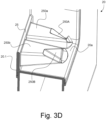
- the locking extensions are advantageously located within a recess 20a formed in an upper portion of the body fluid collection container 20, the locking extensions 250a, 250b being supported by and projecting rearward from a wall section 25 extending partly in the recess 20a, along the front side 20.1 of the container 20 (see especially Figures 3A to 3D ).
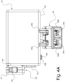
- the locking extensions 250a, 250b are configured to mate with corresponding locking apertures 50a, 50b provided on the spring-loaded interlocking mechanism 50, as shown in particular in Figures 4A , 4E and 6 .
- the overall shape of the locking extensions 250a, 250b and associated locking apertures 50a, 50b may vary, but are preferably chosen in such a way as to facilitate engagement and disengagement of the interlocking mechanism 50 with or from the locking extensions 250a, 250b and ensure a stable and reliable guidance and support of the container 20.
- the spring-loaded interlocking mechanism 50 advantageously extends from a lower side 10.1 of the body fluid meter unit 10 and that the recess 20a formed in the upper portion of the body fluid collection container 20 is configured to entirely receive the spring-loaded interlocking mechanism 50, which also favors and facilitates engagement and disengagement of the container 20.
- the recess 20a in effect advantageously acts as a guide for engagement and disengagement of the container 20 with respect to the spring-loaded interlocking mechanism 50. This also leads to an overall compact assembly as depicted in Figures 1A and 1B .
- the spring-loaded interlocking mechanism 50 is directly coupled to the associated load cell, designated by reference numeral 15, of the body fluid meter unit 10, which load cell 15 is housed within the unit 10.
- an upper housing part 51 of the spring-loaded interlocking mechanism 50 is provided with an extension 51A (also partly visible in Figure 4E ) projecting upward through a corresponding opening (not shown) formed in the lower side 10.1 of the body fluid meter unit 10.
- This upper housing part 51 is secured to a lower housing part 52 to house the various mechanical components of the spring-loaded interlocking mechanism 50 which will be detailed hereafter.
- the load cell 15 is preferably an S-type load cell comprising an S-shaped block that is secured, at an upper end, to a suitable portion of the body fluid meter unit 10 and, at a lower end, to the spring-loaded interlocking mechanism 50 (and the associated container 20, when engaged), thereby allowing a measurement of the load applied on the load cell 15.
- S-type load cells (as well as other types of load cells) are commercially available on the market, for instance from company Mettler-Toledo (Schweiz) GmbH (www.mt.com), and are used for a large variety of applications. Load cells with increased resistance to traction (exceeding e.g. 100 kg of traction or more) are of particular interest with a view to prevent damage to the load cell, for instance as a result of the body fluid collection container 20 getting stuck during movement of the patient's bed or someone stepping up on the body fluid collection container 20.
- the spring-loaded interlocking mechanism 50 comprises at least one spring-loaded release lever cooperating with the aforementioned one or more interlocking members. More precisely, in the illustrated example, two such spring-loaded release levers 55a, 55b are provided, as shown in Figures 1A , 4A to 4E , 5 and 6 , for cooperation with, respectively, the first and second locking extensions 250a, 250b.
- Each of these spring-loaded release levers 55a, 55b comprises a locking portion 55A, respectively 55B, that is partly visible in Figures 4A and 4E and more fully in Figure 5 .
- Each locking portion 55A, 55B is configured to cooperate with a locking section 250A, respectively 250B, provided on the corresponding interlocking member 250a, 250b.
- the locking sections 250A, 250B advantageously take the shape of locking indentations (see also Figures 2A and 3A to 3D ) formed at a distal end of the locking extensions 250a, 250b.
- each locking portion 55A, 55B engages with the associated locking indentation 250A, respectively 250B, upon full engagement of the container 20 with the spring-loaded interlocking mechanism 50, thereby locking the container 20 in place.
- disengagement of the locking portions 55A, 55B from the associated locking indentations 250A, 250B frees the locking extensions 250a, 250b, thereby allowing disengagement of the container 20 from the interlocking mechanism 50.
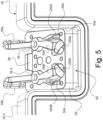
- each release lever 55a, 55b is preferably supported (here between the upper and lower housing parts 51, 52 of the interlocking mechanism 50) so as to pivot about a pivot point 55.1, respectively 55.2, thereby allowing each release lever 55a, 55b to move between a first position (as depicted in Figure 5 ) in which the locking portion 55A, respectively 55B, engages with the locking section 250A, respectively 250B, (thereby preventing disengagement of the body fluid collection container 20) and a second position in which the locking portion 55A, respectively 55B, is disengaged from the locking section 250A, respectively 250B, (thereby allowing disengagement of the body fluid collection container 20).
- the geometry and arrangement of the locking extensions 250a, 250b and of the release levers 55a, 55b (especially the shape of the leading, frontal face of the locking extensions 250a, 250b and the shape of the locking portions 55A, 55B) is chosen in such a way that insertion of the locking extensions 250a, 250b inside the associated locking apertures 50a, 50b causes the release levers 55a, 55b to be pivoted away from their first, engaging position, towards the second, disengaging position.
- the release levers 55a, 55b are automatically pushed back to the first, engaging position under the action of the associated spring element, thereby locking the container 20 in place on the interlocking mechanism 50.
- Disengagement of the container 20 is achieved by simply pressing the two levers 55a, 55b towards each other, against the action of the spring element.
- the tubing 30 includes, as shown, a drip chamber (also referred to as Pasteur drip chamber) 32 placed upstream of the inlet port 20A of the body fluid collection container 20, which drip chamber 32 is secured to the lateral side 10.2 of the body fluid meter unit 10.
- a drip chamber also referred to as Pasteur drip chamber
- this is advantageously achieved by providing the meter unit 10 with a secondary spring-loaded interlocking mechanism 60, secured to the lateral side 10.2 of the meter unit 10, which secondary spring-loaded mechanism is configured to cooperate and interlock with one or more lateral interlocking members (not visible in Figures 1A to 1C ) provided on an outer portion of the drip chamber 32.
- An inlet port 32A of the drip chamber 32 which is connected to the tubing portion 31, is preferably provided with a venting air inlet 320 including an antibacterial air filtration membrane, which improves the flow of body fluid at the inlet port 20A of the container 20, while preventing bacterial contamination.
- a pair of lateral interlocking members are provided for cooperation with the spring-loaded locking mechanism 60, as shown in Figures 2A and 2B .
- the drip chamber 32 comprises first and second lateral locking extensions 360a, 360b acting as lateral interlocking members, which lateral locking extensions 360a, 360b project outwardly from the drip chamber 32.
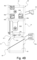
- Each lateral locking extension 360a, 360b is configured to mate with a corresponding locking aperture 60a, respectively 60b, provided on the secondary spring-loaded interlocking mechanism 60, as depicted for instance in Figures 4B and 7A .
- the overall shape of the lateral locking extensions 360a, 360b and associated locking apertures 60a, 60b may once again vary, but are preferably chosen in such a way as to facilitate engagement and disengagement of the secondary interlocking mechanism 60 with or from the lateral locking extensions 360a, 360b of the drip chamber 32.
- the secondary spring-loaded interlocking mechanism 60 is functionally similar to the spring-loaded interlocking mechanism 50 and ensures a stable and reliable connection between the drip chamber 32 and the body fluid meter unit 10.
- the secondary spring-loaded interlocking mechanism 60 includes an outer cover part 61 and an inner cover part 62 secured to the lateral side 10.2 of the body fluid meter unit 10, the outer cover part 61 and inner cover part 62 jointly housing the mechanical components of the secondary spring-loaded interlocking mechanism 60.
- the secondary spring-loaded interlocking mechanism 60 comprises at least one secondary spring-loaded release lever cooperating with the aforementioned one or more lateral interlocking members. More precisely, in the illustrated example, one such spring-loaded release lever 65 is provided, as shown in Figures 1A , 1C , 4A to 4D , 7A and 7B , for cooperation with both the first and second locking extensions 360a, 360b.
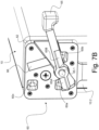
- the spring-loaded release lever 65 comprises first and second locking portions 65A, 65B that are partly visible in Figures 4B and 7A and more fully in Figure 7B . Each locking portion 65A, 65B is configured to cooperate with a locking section 360A, respectively 360B, provided on the corresponding lateral interlocking member 360a, 360b.
- each locking portion 65A, 65B is positioned in such a way as to engage with the associated locking indentation 360A, respectively 360B, upon full engagement of the drip chamber 32 with the secondary spring-loaded interlocking mechanism 60, thereby locking the drip chamber 32 in place.
- disengagement of the locking portions 65A, 65B from the associated locking indentations 360A, 360B frees the lateral locking extensions 360a, 360b, thereby allowing disengagement of the drip chamber 32 from the secondary interlocking mechanism 60.
- the secondary release lever 65 is preferably supported (here between the outer cover part 61 and the inner cover part 62 of the secondary interlocking mechanism 60) so as to pivot about a pivot point 65.1, thereby allowing the release lever 65 to move between a first (lowered) position (as depicted in the illustrations) in which the locking portions 65A, 65B engage with the locking sections 360A, 360B (thereby preventing disengagement of the drip chamber 32) and a second (raised) position in which the locking portions 65A, 65B are disengaged from the locking section 360A, 360B (thereby allowing disengagement of the drip chamber 32).
- the release lever 65 is pushed to the aforementioned first, lowered position under the action of a spring element (not shown) located in a blind recess portion 66 (see Figure 7B ) formed in cover parts 61, 62, above the position of the lever 65.
- a spring element not shown located in a blind recess portion 66 (see Figure 7B ) formed in cover parts 61, 62, above the position of the lever 65.
- the geometry and arrangement of the locking extensions 360a, 360b and of the release lever 65 (especially the shape of the leading, frontal face of the locking extensions 360a, 360b and the shape of the locking portions 65A, 65B) is chosen in such a way that insertion of the locking extensions 360a, 360b inside the associated locking apertures 60a, 60b causes the release lever 65 to be pivoted away from its first, engaging position, towards the second, disengaging position.
- the release lever 65 Upon full and complete engagement of the drip chamber 32, the release lever 65 is automatically pushed back to the first, engaging position under the action of the associated spring element, thereby locking the drip chamber 32 in place on the secondary interlocking mechanism 60. Disengagement of the drip chamber 32 is achieved by simply pushing the lever 65 upward, in the illustrated example, against the action of the spring element.
- the drip chamber 32 is advantageously further provided with a guide member 360c formed as a further lateral extension projecting outwardly from the drip chamber 32, which guide member 360c is configured to mate with a corresponding guiding aperture 60c provided on the secondary spring-loaded interlocking mechanism 60 to ensure a stable connection between the drip chamber 32 and the meter unit 10.
- the tubing 30 preferably further comprises a flexible tubing portion 33 interposed between an outlet port 32B of the drip chamber 32 and the inlet port 20A of the body fluid collection container 20 as shown in Figures 1A to 1C , 2A and 2B .
- this flexible tubing portion 33 may advantageously be configured as a coiled tubing portion, which adequately copes with the fact that the container 20 is suspended under the meter unit 10 and prevents any interference with the measurement process.
- Figure 8 is a functional block diagram illustrating functional electronic components of the body fluid meter unit 10 in accordance with a preferred embodiment.
- the body fluid meter unit 10 is preferably battery-operated and includes a battery 18 providing power to the body fluid meter unit 10.
- the load cell 15 coupled to the body fluid collection container 20 via the spring-loaded interlocking mechanism 50.
- the illustrated meter unit 10 further includes a printed circuit board 100 carrying electronic components necessary to condition and process the sensor signals produced by the load cell 15, including an analog-to-digital (A/D) converter 115 coupled to the load cell 15 and designed to convert analog signals from the load cell 15 into processable digital sensor data.
- the A/D converter 115 is in operative communication with a processing unit 101 (such as a suitable CPU or microcontroller) that is programmed to digitally process the sensor data supplied by the A/D converter to derive the measurement of the quantity and/or flow rate of the body fluid accumulating in the container 20.
- a processing unit 101 such as a suitable CPU or microcontroller
- the processing unit 101 is preferably in further operative communication with additional electronic components of the body fluid meter unit 10 that are likewise provided on the PCB 100, namely:
- the wireless transceiver 105 is in particular of use to wirelessly communicate data representative of the measured quantity and/or flow rate of body fluid to a remote device such as a computer, tablet or the like. Additional software could be implemented on said computer or tablet to provide high-level information to the end-user, such as an indication of the actual flow rate of body fluid being recorded, as well as statistics illustrative of the evolution of the body fluid output and other information relating to the clinical condition of the patient.
- the NFC transceiver 106 may especially be of interest to establish a secure communication link between the body fluid meter unit 10 and a configurator device for the purpose e.g. of configurating and setting up the body fluid meter unit 10.
- This NFC transceiver 106 may in particular be of use for authentication purposes to ensure that only authorized personnel can have administrative access to functionalities and configuration options of the body fluid meter unit 10.
- the battery 18 may especially be a rechargeable battery, such as a lithium-ion battery, in which case a suitable monitoring and control of the battery charge status and charge cycle needs to be ensured.
- Reference numeral 10A in Figure 8 designates a suitable connector for connection to an external battery charger, which connector 10A is also visible in Figures 4A , 4B and 4D , here provided on the lower side 10.1 of the meter unit 10.
- Reference numeral 10B in Figures 4A , 4B and 4D designates a status LED (not shown in Figure 8 ) which can be used to provide a visual indication of the power status of the body fluid meter unit 10 and of the charge status of the battery 18.
- the accelerometer 120 is of particular interest to detect and monitor movements of the body fluid meter unit 10 that could interfere with or otherwise affect the measurement accuracy. In that respect, movements that could cause spurious sensor signals from the load cell 15 can be detected by the accelerometer and the relevant spurious data be discarded or filtered out.
- the accelerometer 120 may in particular be a triaxial (or three-dimensional) accelerometer 120 configured to detect movements in all directions.
- the processing unit 101 can be configured to monitor the quantity and/or flow rate of body fluid and allow setting up of corresponding detection thresholds to trigger alarms, such as in case the detected quantity or flow rate of body fluid exceeds or falls under a predetermined detection threshold.
- An alarm may for instance be set up to be triggered when the body fluid collection container 20 needs to be emptied.
- the body fluid meter unit 10 could additionally be provided with an integrated sound-generating device and/or visual indicator to generate an audible and/or visual alarm.
- spring-loaded interlocking mechanism comprising at least one spring-loaded release lever
- this preferred feature is optional, and one may alternatively contemplate to design the spring-loaded interlocking mechanism in such a way that release of the interlocking members is caused by insertion of an adequate tool or dedicated release element.
- the use of one or more spring-loaded release levers is nevertheless preferred in that this greatly facilitates handling operations.
- the spring-loaded interlocking mechanism could alternatively make use of so-called snap-fit interlocking elements that integrate the spring components, namely elements exhibiting elastic interlocking portions or sections.
- the illustrated embodiment nevertheless remains a preferred solution in that all movable components of the spring-loaded interlocking mechanism are an integral part of the body fluid meter unit, which does not negatively impact the complexity of the associated body fluid collection container.
- the production costs of the body fluid collection container per se are therefore comparable to those of conventional body fluid collection containers or bags.
Landscapes
- Health & Medical Sciences (AREA)
- Life Sciences & Earth Sciences (AREA)
- Engineering & Computer Science (AREA)
- Public Health (AREA)
- Veterinary Medicine (AREA)
- Biomedical Technology (AREA)
- Heart & Thoracic Surgery (AREA)
- Medical Informatics (AREA)
- Molecular Biology (AREA)
- Surgery (AREA)
- Animal Behavior & Ethology (AREA)
- General Health & Medical Sciences (AREA)
- Pathology (AREA)
- Physiology (AREA)
- Physics & Mathematics (AREA)
- Biophysics (AREA)
- Urology & Nephrology (AREA)
- Signal Processing (AREA)
- Hematology (AREA)
- Computer Networks & Wireless Communication (AREA)
- Power Engineering (AREA)
- Artificial Intelligence (AREA)
- Computer Vision & Pattern Recognition (AREA)
- Psychiatry (AREA)
- Sampling And Sample Adjustment (AREA)
Description
- The present invention generally relates to a body fluid meter assembly, which invention is in particular intended to be applied for the purpose of measuring diuresis. The invention also relates to a body fluid collection container and a body fluid meter unit suitable for use as part of the body fluid meter assembly.
- Body fluid meter assemblies are known as such in the art, especially for measuring diuresis.
- Collection of urine output is typically carried out by catheterizing the patient, namely by passing a urinary catheter through the urethra of the patient and connecting the other end of the urinary catheter to a container or drainage bag through a length of flexible tubing. Typically, the container or bag collecting urine is supported below the patient from the patient's bed or an associated support system, and urine drains by gravity from the patient through the flexible tubing and into the container or bag.
- A widespread solution for measuring diuresis consists in making manual, visual readings directly on the container or bag collecting urine. Many of these systems use urine collection bags formed of a clear and flexible plastic material provided with indicia in the form of graduations that represents the volume of urine being collected in the bag. In other systems, the urine collection receptacle includes a rigid and clear plastic reservoir in fluid communication with an additional collection bag, the reservoir being likewise provided with indicia in the form of graduations that represents the volume of urine being collected in the reservoir. In this latter case, urine initially flows and is stored in the reservoir, which acts as a measurement chamber, prior to being emptied into the additional collection bag. A determination of the quantity of urine being collected is performed visually at periodic intervals by means of the relevant graduations, which allows to derive an indication of the flow rate of urine. This solution is not entirely satisfactory in that measurement readings on the graduations are inherently inaccurate and dependent upon the caregiver making the relevant measurement readings at precise time intervals. Furthermore, measurement readings are sometimes difficult to make depending on where the system is located. This solution moreover requires emptying the bag or reservoir at regular intervals so that it has room to be filled again.
- US Patent No.
US 4,712,567 A discloses a body fluid meter assembly used for the purpose of measuring diuresis, i.e. monitoring and measuring the quantity of urine produced by a patient during urination. More precisely, the assembly comprises a drainage collection bag configured to collect urine, a measuring and processing unit comprising a load cell and a coupling mechanism configured to releasably couple the drainage collection bag to the load cell, and flexible tubing attached to an inlet port of the drainage collection bag and configured to be connected to a urinary catheter. The drainage collection bag is coupled mechanically to the load cell via a handle assembly that is secured to an upper portion of the bag, which handle assembly is supported onto a pair of arms secured to the load cell. The measuring and processing unit processes sensor data supplied by the load cell and derives a measurement of the amount of urine being collected. In effect, the measuring and processing unit measures urine amount with regard to its weight and converts weight to volume by accounting for urine volumetric mass density. The variation of urine volume over time provides a reliable indication of the urine flow rate, which can be used to monitor the evolution of the clinical condition of the patient. - The coupling mechanism disclosed in US Patent No.
US 4,712,567 A to couple the drainage collection bag to the load cell is not robust or reliable enough, especially in that the drainage collection bag can be inadvertently released, which is not desirable. Furthermore, movements or shocks can unsettle the drainage collection bag and cause erroneous sensor measurements. - Other similar solutions are known in the art, for instance from International (
PCT) Publications Nos. WO 2006/031249 A2 ,WO 2014/036769 A1 ,WO 2017/149272 A1 , US Patent Publication No.US 2010/0228148 A1 and US Patent Publication No.US 2017/0307423 A1 . All of these solutions suffer from substantially the same drawbacks as the solution disclosed in US Patent No.US 4,712,567 A , namely an unreliable and unstable connection between the measuring and processing unit and the collection bag. - There is therefore a need for a solution which prevents inadvertent release of the container used to collect the body fluid and ensures a more reliable and stable connection between the container and the associated measuring and processing unit, while not compromising handling operations.
- US Patent Publication No.
US 2018/0214297 A1 discloses a urine output collection and monitoring system that does not rely upon the use of a load cell to derive a measurement of a quantity and/or flow rate of urine accumulating in a urine collection container. Rather, such measurement is derived by optical means, namely using a light detector array detecting a fan beam signal emitted by a light source through a portion of the urine collection container where urine accumulates. - A general aim of the invention is to provide an improved body fluid meter assembly.
- More precisely, an aim of the invention is to provide such a solution which prevents inadvertent release of the body fluid collection container from the coupling mechanism of the associated body fluid meter unit.
- A further aim of the invention is to provide such a solution which ensures a reliable and stable connection between the body fluid collection container and the associated body fluid meter unit.
- Yet another aim of the invention is to provide such a solution where assembly and disassembly of the body fluid collection container is easy to handle.
- These aims are achieved thanks to the solutions defined in the claims.
- In accordance with the invention, there is provided a body fluid meter assembly, in particular for measuring diuresis, as defined in
claim 1, namely a body fluid meter assembly comprising (i) a body fluid collection container configured to collect body fluid, such as urine, (ii) a body fluid meter unit comprising a load cell and a coupling mechanism configured to releasably couple the body fluid collection container to the load cell, which body fluid meter unit is configured to process sensor data supplied by the load cell and derive a measurement of a quantity and/or flow rate of the body fluid accumulating in the body fluid collection container as a function of load applied on the load cell, and (iii) tubing attached to an inlet port of the body fluid collection container and configured to be connected to a source of the body fluid. According to the invention, the body fluid collection container is a substantially rigid container and the coupling mechanism is a spring-loaded interlocking mechanism configured to cooperate with one or more interlocking members provided on the body fluid collection container and interlock with the body fluid collection container to form a stable connection between the body fluid meter unit and the body fluid collection container. - In accordance with a preferred embodiment, the spring-loaded interlocking mechanism comprises at least one spring-loaded release lever comprising a locking portion configured to cooperate with a locking section (preferably shaped as a locking indentation) provided on a corresponding one of the one or more interlocking members. In particular, each spring-loaded release lever may be supported so as to pivot between a first position in which the locking portion of the spring-loaded release lever engages with the locking section of the corresponding interlocking member and prevents disengagement of the body fluid collection container and a second position in which the locking portion of the spring-loaded release lever is disengaged from the locking section of the corresponding interlocking member and allows disengagement of the body fluid collection container.
- In accordance with an embodiment of the invention, the body fluid collection container comprises at least one locking extension acting as interlocking member and projecting from the body fluid collection container, each locking extension being configured to mate with a corresponding locking aperture provided on the spring-loaded interlocking mechanism. More specifically, referring to the preferred embodiment discussed in the preceding paragraph, the body fluid collection container preferably comprises first and second locking extensions acting as interlocking members and projecting from the body fluid collection container, each locking extension being configured to mate with a corresponding locking aperture provided on the spring-loaded interlocking mechanism. In this latter preferred context, the spring-loaded interlocking mechanism comprises first and second spring-loaded release levers cooperating respectively with the first and second locking extensions.
- Each of the aforementioned locking extensions may in particular project substantially horizontally from the body fluid collection container, preferably rearward from a front side of the body fluid collection container.
- In accordance with a particularly preferred embodiment, the spring-loaded interlocking mechanism extends from a lower side of the body fluid meter unit and an upper portion of the body fluid collection container exhibits a recess configured to receive the spring-loaded interlocking mechanism, each interlocking member being located within the recess. This ensures reliable guidance of the body fluid collection container upon engaging or disengaging the body fluid collection container from the spring-loaded interlocking mechanism.
- By way of preference, a portion of the tubing is secured to a lateral side of the body fluid meter unit. In particular, the tubing may advantageously include a drip chamber placed upstream of the inlet port of the body fluid collection container. In this latter context, the body fluid meter unit may further comprise a secondary spring-loaded interlocking mechanism provided on the lateral side of the body fluid meter unit, which secondary spring-loaded interlocking mechanism is configured to cooperate and interlock with one or more lateral interlocking members provided on an outer portion of the drip chamber. This ensures that any tension applied on the tubing will not cause inadvertent movement of the body fluid collection container that may otherwise interfere with the measurement process. The inlet port of the drip chamber is preferably provided with a venting air inlet including an antibacterial air filtration membrane, which ensures optimal flow of the body fluid at the inlet port and prevents bacterial contamination.
- The aforementioned secondary spring-loaded interlocking mechanism may in particular comprise at least one secondary spring-loaded release lever comprising at least one locking portion configured to cooperate with a locking section (preferably shaped as a locking indentation) provided on a corresponding one of the one or more lateral interlocking members. Preferably, the secondary spring-loaded release lever is supported so as to pivot between a first position in which the locking portion of the secondary spring-loaded release lever engages with the locking section of the corresponding lateral interlocking member and prevents disengagement of the drip chamber and a second position in which the locking portion of the secondary spring-loaded release lever is disengaged from the locking section of the corresponding lateral interlocking member and allows disengagement of the drip chamber.
- In accordance with a variant of the invention, the drip chamber comprises at least one lateral locking extension acting as lateral interlocking member and projecting outwardly from the drip chamber, each lateral locking extension being configured to mate with a corresponding locking aperture provided on the secondary spring-loaded interlocking mechanism. More specifically, referring to the embodiment discussed in the preceding paragraph, the drip chamber preferably comprises first and second lateral locking extensions acting as lateral interlocking members and projecting from the drip chamber, each lateral locking extension being configured to mate with a corresponding locking aperture provided on the secondary spring-loaded interlocking mechanism. In this latter preferred context, the secondary spring-loaded interlocking mechanism comprises only one said secondary spring-loaded release lever cooperating with both of the first and second lateral locking extensions.
- By way of preference, the tubing further includes a flexible tubing portion interposed between an outlet port of the drip chamber and the inlet port of the body fluid collection container. This flexible tubing portion may in particular be configured as a coiled tubing portion.
- In accordance with another aspect of the invention, the body fluid meter unit comprises a processing unit in operative communication with an analog-to-digital (A/D) converter coupled to the load cell to convert analog signals from the load cell into digital sensor data, the processing unit being configured to digitally process the sensor data supplied by the analog-to-digital (A/D) converter to derive the measurement of the quantity and/or flow rate of the body fluid accumulating in the body fluid collection container. Preferably, the processing unit is in further operative communication with one or more of the following electronic components of the body fluid meter unit, namely:
- a wireless transceiver configured to establish a wireless communication with a remote receiver and communicate data wirelessly to the remote receiver;
- a near-field communication (NFC) transceiver configured to establish a near-field communication link with an external NFC device;
- a battery controller coupled to a battery, in particular a rechargeable battery, supplying power to the body fluid meter unit, which battery controller is configured to monitor a charge status of the battery; and
- an accelerometer configured to detect and monitor movement of the body fluid meter unit.
- Further claimed in
independent claim 10 is a body fluid collection container configured to collect body fluid, such as urine, the body fluid collection container being suitable for use as part of the aforementioned body fluid meter assembly, which body fluid collection container is a substantially rigid container comprising one or more interlocking members configured to cooperate and interlock with the spring-loaded interlocking mechanism of the body fluid meter unit. This body fluid collection container is preferably further characterized by the relevant features of the body fluid collection container discussed hereabove in connection with the body fluid meter assembly of the invention, which preferred features are recited in claims 11 and 12. - Also claimed in independent claim 13 is a body fluid meter unit suitable for use as part of the aforementioned body fluid meter assembly, which body fluid meter unit comprises a load cell and a coupling mechanism configured to releasably couple the body fluid collection container of the body fluid meter assembly to the load cell, the body fluid meter unit being configured to process sensor data supplied by the load cell and derive a measurement of a quantity and/or flow rate of the body fluid accumulating in the body fluid collection container as a function of load applied on the load cell. The coupling mechanism is likewise a spring-loaded interlocking mechanism configured to cooperate and interlock with one or more interlocking members provided on the body fluid collection container. This body fluid meter unit is preferably further characterized by the relevant features of the body fluid meter unit discussed hereabove in connection with the body fluid meter assembly of the invention, which preferred features are recited in
claims 14 and 15. - Further advantageous embodiments of the invention are discussed below.
- Other features and advantages of the present invention will appear more clearly from reading the following detailed description of embodiments of the invention which are presented solely by way of non-restrictive examples and illustrated by the attached drawings in which:
-
Figure 1A is a schematic perspective view of a body fluid meter assembly, as seen from a front side, in accordance with a preferred embodiment of the invention, which body fluid meter assembly includes a body fluid meter unit that is coupled to a body fluid collection container via a spring-loaded interlocking mechanism; -
Figure 1B is a schematic perspective view of the body fluid meter assembly ofFigure 1A , as seen from a rear side; -
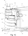
Figure 1C is an enlarged partial perspective view of a lateral side of the body fluid meter unit ofFigures 1A and1B , where tubing is attached to an inlet port of the body fluid collection container; -
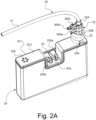
Figure 2A is a schematic perspective view of the assembly ofFigures 1A to 1C , with the body fluid meter unit removed from the body fluid collection container and showing the body fluid collection container and associated tubing from a rear side; -
Figure 2B is an enlarged partial perspective view of a portion of the tubing upstream of the inlet port of the body fluid collection container where a drip chamber is provided; -
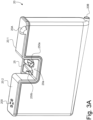
Figure 3A is a schematic perspective view, as seen from a rear side, of the body fluid collection container forming part of the assembly shown inFigures 1A to 1C ; -
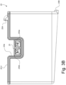
Figure 3B is a rear view of the body fluid collection container ofFigure 3A ; -
Figure 3C is a top view of the body fluid collection container ofFigure 3A ; -
Figure 3D is an enlarged partial perspective view of an upper portion of the body fluid collection container ofFigure 3A showing a pair of interlocking members used to couple the body fluid collection container to the associated spring-loaded interlocking mechanism of the body fluid meter unit as shown for instance inFigures 1A to 1C ,4A to 4E ,5 and6 ; -
Figure 4A is a front view of the body fluid meter unit forming part of the assembly shown inFigures 1A to 1C ; -
Figure 4B is a side view of the body fluid meter unit ofFigure 4A ; -
Figure 4C is a top view of the body fluid meter unit ofFigure 4A ; -
Figure 4D is a bottom view of the body fluid meter unit ofFigure 4A ; -
Figure 4E is an enlarged partial perspective view of the spring-loaded interlocking mechanism of the body fluid meter unit ofFigure 4A ; -
Figure 5 is an enlarged partial perspective view of a part of the spring-loaded interlocking mechanism ofFigure 4E coupled to the pair of interlocking members of the body fluid collection container, with an upper housing part of the spring-loaded interlocking mechanism being omitted for the sake of illustration; -
Figure 6 is a partial perspective view of the spring-loaded interlocking mechanism ofFigure 4E secured to a load cell of the body fluid meter unit; -
Figure 7A is an enlarged partial perspective view of a secondary spring-loaded interlocking mechanism provided on the lateral side of the body fluid meter unit for coupling to the drip chamber shown inFigures 2A and2B ; -
Figure 7B is an enlarged partial perspective view of a part of the secondary spring-loaded interlocking mechanism ofFigure 7A , with an outer cover part of the secondary spring-loaded interlocking mechanism being omitted for the sake of illustration; and -
Figure 8 is a functional block diagram illustrating functional electronic components of the body fluid meter unit according to a preferred embodiment. - The present invention will be described in relation to various illustrative embodiments. It shall be understood that the scope of the invention encompasses all combinations and sub-combinations of the features of the embodiments disclosed herein.
- As described herein, when two or more parts or components are described as being connected, secured, attached or coupled to one another, they can be so connected, secured, attached or coupled directly to each other or through one or more intermediary parts.
- The invention will be described in relation to various embodiments of a body fluid meter assembly as shown in
Figures 1A-C to 8 , which assembly is especially intended to measure diuresis. -
Figures 1A to 1C are illustrative of a particularly preferred embodiment of the body fluid meter assembly according to the invention, which assembly is generally designated byreference numeral 1. The bodyfluid meter assembly 1 basically includes three main components, namely a bodyfluid meter unit 10, a bodyfluid collection container 20 configured to collect body fluid (i.e. urine in the present example), andtubing 30 attached to aninlet port 20A of the bodyfluid collection container 20 and configured to be connected to a source of the body fluid (namely a urinary catheter in the present instance, not shown) by means oftubing portion 31. While not specifically shown, theinlet port 20A may advantageously be provided with an anti-reflux valve to prevent retrograde flow of urine into thetubing 30, thereby preventing retrograde migration of bacteria. - The body
fluid meter unit 10 comprises a load cell (not shown inFigures 1A to 1C , but visible inFigure 6 ) and a coupling mechanism configured to releasably couple the body fluid collection container to the load cell (see also the functional diagram ofFigure 8 ). The bodyfluid meter unit 10 is in essence configured to process sensor data supplied by the load cell and derive a measurement of a quantity and/or flow rate of the urine accumulating in the bodyfluid collection container 20 as a function of load applied on the load cell. The basic measurement principle is known per se in the art, for instance from US Patent No.US 4,712,567 A . - In use, the body
fluid meter unit 10 is attached to a bed frame, or to a separate, stable support structure, by means of a suitable attachment mechanism (not shown), such as fastening straps or clamps. A suitable attachment mechanism may in particular be provided on a rear side of the bodyfluid meter unit 10. - Improvements are achieved in terms of measurement accuracy and reliability thanks to the invention. More specifically, in the context of the present invention, use is made of a substantially rigid container as the body
fluid collection container 20, which ensures that accumulation of urine in the container is made in a deterministic way and does not lead to uncontrolled deformation of the collection container, which could negatively impact measurement accuracy and reliability. In that regard, the bodyfluid collection container 20 can be made of any suitably rigid material, including plastic materials, such as polycarbonates. The material can be opaque or substantially transparent, in which case thecontainer 20 could additionally be provided with graduations, as known in the art, to allow visual measurements of the diuresis. - As is conventional in the art, the
container 20 may be provided with adrainage port 20B to allow emptying of thecontainer 20. While not shown, a suitable, manually-actuatable rotary flush valve could be provided at thedrainage port 20B to facilitate the emptying operation. In that respect, an upper side 20.2 of the bodyfluid collection container 20 can additionally be provided with a venting air inlet 200 (with antibacterial air filtration membrane) which ensures optimal and quick emptying of thecontainer 20. - Furthermore, the coupling mechanism used to couple the
container 20 to themeter unit 10 is specifically designed as a spring-loaded interlocking mechanism, designated byreference numeral 50, that is configured to cooperate with one or more interlocking members (not visible inFigures 1A to 1C ) provided on thecontainer 20. This is a fundamental difference compared to the known solutions that make use of rather rudimentary handle and hook arrangements. Thanks to the invention, a stable connection is formed between the bodyfluid meter unit 10 and the bodyfluid collection container 20. Furthermore, inadvertent release of thecontainer 20 from themeter unit 10 is prevented. While more robust and reliable, this solution does not negatively impact handling operations, as thecontainer 20 can easily be coupled to or uncoupled from themeter unit 10 by simple engagement or disengagement of the interlockingmechanism 50 as this will be explained below. - In the illustrated example, a pair of interlocking members are provided for cooperation with the spring-loaded
locking mechanism 50, as shown for instance inFigure 2A andFigures 3A to 3D . More precisely, first andsecond locking extensions extensions fluid collection container 20. By way of preference, as shown, each lockingextension fluid collection container 20, namely rearward from a front side 20.1 of the bodyfluid collection container 20. In the illustrated example, the locking extensions are advantageously located within arecess 20a formed in an upper portion of the bodyfluid collection container 20, the lockingextensions wall section 25 extending partly in therecess 20a, along the front side 20.1 of the container 20 (see especiallyFigures 3A to 3D ). - The locking
extensions corresponding locking apertures interlocking mechanism 50, as shown in particular inFigures 4A ,4E and6 . The overall shape of thelocking extensions apertures mechanism 50 with or from the lockingextensions container 20. - In the illustrated example, one may appreciate that the spring-loaded
interlocking mechanism 50 advantageously extends from a lower side 10.1 of the bodyfluid meter unit 10 and that therecess 20a formed in the upper portion of the bodyfluid collection container 20 is configured to entirely receive the spring-loadedinterlocking mechanism 50, which also favors and facilitates engagement and disengagement of thecontainer 20. Therecess 20a in effect advantageously acts as a guide for engagement and disengagement of thecontainer 20 with respect to the spring-loadedinterlocking mechanism 50. This also leads to an overall compact assembly as depicted inFigures 1A and1B . - As shown in greater detail in
Figure 6 , the spring-loadedinterlocking mechanism 50 is directly coupled to the associated load cell, designated byreference numeral 15, of the bodyfluid meter unit 10, which loadcell 15 is housed within theunit 10. To this end, anupper housing part 51 of the spring-loadedinterlocking mechanism 50 is provided with anextension 51A (also partly visible inFigure 4E ) projecting upward through a corresponding opening (not shown) formed in the lower side 10.1 of the bodyfluid meter unit 10. Thisupper housing part 51 is secured to alower housing part 52 to house the various mechanical components of the spring-loadedinterlocking mechanism 50 which will be detailed hereafter. - As this is readily visible in
Figure 6 , theload cell 15 is preferably an S-type load cell comprising an S-shaped block that is secured, at an upper end, to a suitable portion of the bodyfluid meter unit 10 and, at a lower end, to the spring-loaded interlocking mechanism 50 (and the associatedcontainer 20, when engaged), thereby allowing a measurement of the load applied on theload cell 15. S-type load cells (as well as other types of load cells) are commercially available on the market, for instance from company Mettler-Toledo (Schweiz) GmbH (www.mt.com), and are used for a large variety of applications. Load cells with increased resistance to traction (exceeding e.g. 100 kg of traction or more) are of particular interest with a view to prevent damage to the load cell, for instance as a result of the bodyfluid collection container 20 getting stuck during movement of the patient's bed or someone stepping up on the bodyfluid collection container 20. - By way of preference, the spring-loaded
interlocking mechanism 50 comprises at least one spring-loaded release lever cooperating with the aforementioned one or more interlocking members. More precisely, in the illustrated example, two such spring-loaded release levers 55a, 55b are provided, as shown inFigures 1A ,4A to 4E ,5 and6 , for cooperation with, respectively, the first andsecond locking extensions portion 55A, respectively 55B, that is partly visible inFigures 4A and4E and more fully inFigure 5 . Each lockingportion locking section 250A, respectively 250B, provided on the corresponding interlockingmember sections Figures 2A and3A to 3D ) formed at a distal end of thelocking extensions Figure 5 (where theupper housing part 51 of the spring-loadedinterlocking mechanism 50 has been omitted for the purpose of illustration), each lockingportion indentation 250A, respectively 250B, upon full engagement of thecontainer 20 with the spring-loadedinterlocking mechanism 50, thereby locking thecontainer 20 in place. Conversely, disengagement of the lockingportions indentations locking extensions container 20 from the interlockingmechanism 50. - As this is more readily visible in
Figure 5 , eachrelease lever lower housing parts release lever Figure 5 ) in which the lockingportion 55A, respectively 55B, engages with thelocking section 250A, respectively 250B, (thereby preventing disengagement of the body fluid collection container 20) and a second position in which the lockingportion 55A, respectively 55B, is disengaged from thelocking section 250A, respectively 250B, (thereby allowing disengagement of the body fluid collection container 20). - By default, when no action is applied on the release levers 55a, 55b, the release levers 55a, 55b are pushed to the aforementioned first position under the action of a spring element (not shown) located in a recess portion 56 (see
Figure 5 ) between the tworelease levers - The geometry and arrangement of the
locking extensions locking extensions portions locking extensions locking apertures container 20, the release levers 55a, 55b are automatically pushed back to the first, engaging position under the action of the associated spring element, thereby locking thecontainer 20 in place on the interlockingmechanism 50. Disengagement of thecontainer 20 is achieved by simply pressing the twolevers - A further advantageous aspect of the invention will now be discussed with reference to
Figures 1A to 1C ,2A ,2B ,4A to 4E ,7A and7B , namely in relation to thetubing 30 that is attached to theinlet port 20A of the bodyfluid collection container 20. Considering that thetubing 30 is connected to thecontainer 20, which is suspended below themeter unit 10, movement of thetubing 30, such as caused by manipulation of thetubing portion 31, may negatively impact the measurement accuracy. To prevent this from happening, a portion of thetubing 30 is preferably secured to a lateral side 10.2 of the bodyfluid meter unit 10, which in effect isolates the bodyfluid collection container 20 from any perturbation caused by movement of thetubing 30. - Even more preferably, the
tubing 30 includes, as shown, a drip chamber (also referred to as Pasteur drip chamber) 32 placed upstream of theinlet port 20A of the bodyfluid collection container 20, which dripchamber 32 is secured to the lateral side 10.2 of the bodyfluid meter unit 10. In the illustrated example, this is advantageously achieved by providing themeter unit 10 with a secondary spring-loadedinterlocking mechanism 60, secured to the lateral side 10.2 of themeter unit 10, which secondary spring-loaded mechanism is configured to cooperate and interlock with one or more lateral interlocking members (not visible inFigures 1A to 1C ) provided on an outer portion of thedrip chamber 32. - An
inlet port 32A of thedrip chamber 32, which is connected to thetubing portion 31, is preferably provided with a ventingair inlet 320 including an antibacterial air filtration membrane, which improves the flow of body fluid at theinlet port 20A of thecontainer 20, while preventing bacterial contamination. - In the illustrated example, a pair of lateral interlocking members are provided for cooperation with the spring-loaded
locking mechanism 60, as shown inFigures 2A and2B . More precisely, thedrip chamber 32 comprises first and secondlateral locking extensions lateral locking extensions drip chamber 32. Eachlateral locking extension corresponding locking aperture 60a, respectively 60b, provided on the secondary spring-loadedinterlocking mechanism 60, as depicted for instance inFigures 4B and7A . The overall shape of thelateral locking extensions apertures secondary interlocking mechanism 60 with or from thelateral locking extensions drip chamber 32. - The secondary spring-loaded
interlocking mechanism 60 is functionally similar to the spring-loadedinterlocking mechanism 50 and ensures a stable and reliable connection between thedrip chamber 32 and the bodyfluid meter unit 10. In the illustrated example, the secondary spring-loadedinterlocking mechanism 60 includes anouter cover part 61 and aninner cover part 62 secured to the lateral side 10.2 of the bodyfluid meter unit 10, theouter cover part 61 andinner cover part 62 jointly housing the mechanical components of the secondary spring-loadedinterlocking mechanism 60. - By way of preference, the secondary spring-loaded
interlocking mechanism 60 comprises at least one secondary spring-loaded release lever cooperating with the aforementioned one or more lateral interlocking members. More precisely, in the illustrated example, one such spring-loadedrelease lever 65 is provided, as shown inFigures 1A ,1C ,4A to4D ,7A and7B , for cooperation with both the first andsecond locking extensions release lever 65 comprises first andsecond locking portions Figures 4B and7A and more fully inFigure 7B . Each lockingportion locking section 360A, respectively 360B, provided on the corresponding lateral interlockingmember sections Figure 2B ) formed at a distal end of thelocking extensions Figure 7A andFigure 7B (where theouter cover part 61 of the secondary spring-loadedinterlocking mechanism 60 has been omitted for the purpose of illustration), each lockingportion indentation 360A, respectively 360B, upon full engagement of thedrip chamber 32 with the secondary spring-loadedinterlocking mechanism 60, thereby locking thedrip chamber 32 in place. Conversely, disengagement of the lockingportions indentations lateral locking extensions drip chamber 32 from thesecondary interlocking mechanism 60. - As this is more readily visible in
Figure 7B , thesecondary release lever 65 is preferably supported (here between theouter cover part 61 and theinner cover part 62 of the secondary interlocking mechanism 60) so as to pivot about a pivot point 65.1, thereby allowing therelease lever 65 to move between a first (lowered) position (as depicted in the illustrations) in which thelocking portions sections locking portions locking section - By default, when no action is applied on the
release lever 65, therelease lever 65 is pushed to the aforementioned first, lowered position under the action of a spring element (not shown) located in a blind recess portion 66 (seeFigure 7B ) formed incover parts lever 65. - The geometry and arrangement of the
locking extensions locking extensions portions locking extensions locking apertures release lever 65 to be pivoted away from its first, engaging position, towards the second, disengaging position. Upon full and complete engagement of thedrip chamber 32, therelease lever 65 is automatically pushed back to the first, engaging position under the action of the associated spring element, thereby locking thedrip chamber 32 in place on thesecondary interlocking mechanism 60. Disengagement of thedrip chamber 32 is achieved by simply pushing thelever 65 upward, in the illustrated example, against the action of the spring element. - As this can be appreciated from looking at the illustrations of
Figures 2A ,2B ,4B ,7A and7B , thedrip chamber 32 is advantageously further provided with aguide member 360c formed as a further lateral extension projecting outwardly from thedrip chamber 32, which guidemember 360c is configured to mate with a corresponding guidingaperture 60c provided on the secondary spring-loadedinterlocking mechanism 60 to ensure a stable connection between thedrip chamber 32 and themeter unit 10. - In addition to the
aforementioned drip chamber 32, thetubing 30 preferably further comprises aflexible tubing portion 33 interposed between anoutlet port 32B of thedrip chamber 32 and theinlet port 20A of the bodyfluid collection container 20 as shown inFigures 1A to 1C ,2A and2B . As illustrated, thisflexible tubing portion 33 may advantageously be configured as a coiled tubing portion, which adequately copes with the fact that thecontainer 20 is suspended under themeter unit 10 and prevents any interference with the measurement process. -
Figure 8 is a functional block diagram illustrating functional electronic components of the bodyfluid meter unit 10 in accordance with a preferred embodiment. In the illustrated embodiment, the bodyfluid meter unit 10 is preferably battery-operated and includes abattery 18 providing power to the bodyfluid meter unit 10. Also schematically depicted inFigure 8 is theload cell 15 coupled to the bodyfluid collection container 20 via the spring-loadedinterlocking mechanism 50. - The illustrated
meter unit 10 further includes a printedcircuit board 100 carrying electronic components necessary to condition and process the sensor signals produced by theload cell 15, including an analog-to-digital (A/D)converter 115 coupled to theload cell 15 and designed to convert analog signals from theload cell 15 into processable digital sensor data. The A/D converter 115 is in operative communication with a processing unit 101 (such as a suitable CPU or microcontroller) that is programmed to digitally process the sensor data supplied by the A/D converter to derive the measurement of the quantity and/or flow rate of the body fluid accumulating in thecontainer 20. - The
processing unit 101 is preferably in further operative communication with additional electronic components of the bodyfluid meter unit 10 that are likewise provided on thePCB 100, namely: - a
wireless transceiver 105 configured to establish a wireless communication with a remote receiver and communicate data wirelessly to the remote receiver; - a near-field communication (NFC)
transceiver 106 configured to establish a near-field communication link with an external NFC device; - a
battery controller 118 coupled to thebattery 18, whichbattery controller 118 is configured to monitor a charge status of thebattery 18; and - an
accelerometer 120 configured to detect and monitor movement of the bodyfluid meter unit 10. - The
wireless transceiver 105 is in particular of use to wirelessly communicate data representative of the measured quantity and/or flow rate of body fluid to a remote device such as a computer, tablet or the like. Additional software could be implemented on said computer or tablet to provide high-level information to the end-user, such as an indication of the actual flow rate of body fluid being recorded, as well as statistics illustrative of the evolution of the body fluid output and other information relating to the clinical condition of the patient. - The
NFC transceiver 106 may especially be of interest to establish a secure communication link between the bodyfluid meter unit 10 and a configurator device for the purpose e.g. of configurating and setting up the bodyfluid meter unit 10. ThisNFC transceiver 106 may in particular be of use for authentication purposes to ensure that only authorized personnel can have administrative access to functionalities and configuration options of the bodyfluid meter unit 10. - With regard to the
battery controller 118, thebattery 18 may especially be a rechargeable battery, such as a lithium-ion battery, in which case a suitable monitoring and control of the battery charge status and charge cycle needs to be ensured.Reference numeral 10A inFigure 8 designates a suitable connector for connection to an external battery charger, whichconnector 10A is also visible inFigures 4A ,4B and4D , here provided on the lower side 10.1 of themeter unit 10.Reference numeral 10B inFigures 4A ,4B and4D designates a status LED (not shown inFigure 8 ) which can be used to provide a visual indication of the power status of the bodyfluid meter unit 10 and of the charge status of thebattery 18. - The
accelerometer 120 is of particular interest to detect and monitor movements of the bodyfluid meter unit 10 that could interfere with or otherwise affect the measurement accuracy. In that respect, movements that could cause spurious sensor signals from theload cell 15 can be detected by the accelerometer and the relevant spurious data be discarded or filtered out. Theaccelerometer 120 may in particular be a triaxial (or three-dimensional)accelerometer 120 configured to detect movements in all directions. - Further electronic components or functionalities could be contemplated. In particular, the
processing unit 101 can be configured to monitor the quantity and/or flow rate of body fluid and allow setting up of corresponding detection thresholds to trigger alarms, such as in case the detected quantity or flow rate of body fluid exceeds or falls under a predetermined detection threshold. An alarm may for instance be set up to be triggered when the bodyfluid collection container 20 needs to be emptied. In that context, the bodyfluid meter unit 10 could additionally be provided with an integrated sound-generating device and/or visual indicator to generate an audible and/or visual alarm. - Various modifications and/or improvements may be made to the above-described embodiments without departing from the scope of the invention as defined by the appended claims.
- For instance, while the illustrated embodiments show a spring-loaded interlocking mechanism comprising at least one spring-loaded release lever, this preferred feature is optional, and one may alternatively contemplate to design the spring-loaded interlocking mechanism in such a way that release of the interlocking members is caused by insertion of an adequate tool or dedicated release element. The use of one or more spring-loaded release levers is nevertheless preferred in that this greatly facilitates handling operations.
- In addition, the spring-loaded interlocking mechanism could alternatively make use of so-called snap-fit interlocking elements that integrate the spring components, namely elements exhibiting elastic interlocking portions or sections. The illustrated embodiment nevertheless remains a preferred solution in that all movable components of the spring-loaded interlocking mechanism are an integral part of the body fluid meter unit, which does not negatively impact the complexity of the associated body fluid collection container. The production costs of the body fluid collection container per se are therefore comparable to those of conventional body fluid collection containers or bags.
-
- 1
- body fluid meter assembly (e.g. diuresis meter assembly)
- 10
- body fluid meter unit of body fluid meter assembly 1 (e.g. diuresis meter unit)
- 10A
- battery charger connector
- 10B
- status LED
- 10.1
- lower side of body
fluid meter unit 10 - 10.2
- lateral side of body
fluid meter unit 10 - 15
- load cell (e.g. S-beam type load cell)
- 18
- (rechargeable) battery
- 20
- body fluid collection container of body
fluid meter assembly 1 configured to collect body fluid (e.g. urine) - 20a
- recess formed in upper portion of body
fluid collection container 20 and configured to receive spring-loadedinterlocking mechanism 50 - 20A
- inlet port of body
fluid collection container 20 - 20B
- drainage port of body
fluid collection container 20 - 20.1
- front side of body
fluid collection container 20 - 20.2
- upper side of body
fluid collection container 20 - 25
- wall section extending in
recess 20a, along front side 20.1 of bodyfluid collection container 20 and supportinginterlocking members - 30
- tubing of body
fluid meter assembly 1 - 31
- tubing portion connected to source of body fluid (e.g. urinary catheter)
- 32
- drip chamber
- 32A
- inlet port of
drip chamber 32 - 32B
- outlet port of
drip chamber 32 - 33
- flexible tubing portion (e.g. coiled tubing portion) interposed between
outlet port 32B ofdrip chamber 32 andinlet port 20A of bodyfluid collection container 20 - 50
- spring-loaded interlocking mechanism (coupling mechanism) configured to releasably couple the body
fluid collection container 20 to theload cell 15 - 50a
- (first) locking aperture of spring-loaded
interlocking mechanism 50 configured to receive interlockingmember 250a - 50b
- (second) locking aperture of spring-loaded
interlocking mechanism 50 configured to receive interlockingmember 250b - 51
- upper housing part of spring-loaded
interlocking mechanism 50 - 51A
- extension of
upper housing part 51 secured to loadcell 15 - 52
- lower housing part of spring-loaded
interlocking mechanism 50 - 55a
- (first) spring-loaded release lever configured to cooperate with interlocking
member 250a - 55A
- locking portion of spring-loaded
release lever 55a configured to cooperate withlocking section 250A provided on interlockingmember 250a - 55.1
- pivot point of spring-loaded
release lever 55a - 55b
- (second) spring-loaded release lever configured to cooperate with interlocking
member 250b - 55B
- locking portion of spring-loaded
release lever 55b configured to cooperate withlocking section 250B provided on interlockingmember 250b - 55.2
- pivot point of spring-loaded
release lever 55b - 56
- recess portion configured to receive spring element acting on
release levers - 60
- secondary spring-loaded interlocking mechanism
- 60a
- (first) locking aperture of secondary spring-loaded
interlocking mechanism 60 configured to receive interlockingmember 360a - 60b
- (second) locking aperture of secondary spring-loaded
interlocking mechanism 60 configured to receive interlockingmember 360b - 60c
- guiding aperture of secondary spring-loaded
interlocking mechanism 60 configured to receiveguide member 360c - 61
- outer cover part of secondary spring-loaded
interlocking mechanism 60 - 62
- inner cover part of secondary spring-loaded interlocking mechanism 60 (secured to lateral side 10.2 of body fluid meter unit 10)
- 65
- secondary spring-loaded release lever configured to cooperate with interlocking
members - 65A
- (first) locking portion of secondary spring-loaded
release lever 65 configured to cooperate withlocking section 360A provided on interlockingmember 360a - 65B
- (second) locking portion of secondary spring-loaded
release lever 65 configured to cooperate withlocking section 360B provided on interlockingmember 360b - 65.1
- pivot point of secondary spring-loaded
release lever 65 - 66
- recess portion configured to receive spring element acting on
release lever 65 - 100
- printed circuit board (PCB)
- 101
- processing unit (e.g. CPU)
- 105
- wireless transceiver
- 106
- near-field communication (NFC) transceiver
- 115
- analog-to-digital (A/D) converter
- 118
- battery controller
- 120
- accelerometer
- 200
- venting air inlet (with antibacterial air filtration membrane) provided on upper side 20.2 of body
fluid collection container 20 - 250a
- (first) interlocking member (e.g. first locking extension) provided on body
fluid collection container 20 and configured to cooperate with spring-loadedinterlocking mechanism 50 - 250A
- locking section (e.g. locking indentation) of interlocking
member 250a configured to engage with (e.g. receive) lockingportion 55A of spring-loadedrelease lever 55a - 250b
- (second) interlocking member (e.g. second locking extension) provided on body
fluid collection container 20 and configured to cooperate with spring-loadedinterlocking mechanism 50 - 250B
- locking section (e.g. locking indentation) of interlocking
member 250b configured to engage with (e.g. receive) lockingportion 55B of spring-loadedrelease lever 55b - 320
- venting air inlet (with antibacterial air filtration membrane) provided at
inlet port 32A ofdrip chamber 32 - 360a
- (first) lateral interlocking member (e.g. first lateral locking extension) provided on outer portion of
drip chamber 32 and configured to cooperate with secondary spring-loadedinterlocking mechanism 60 - 360A
- locking section (e.g. locking indentation) of lateral interlocking
member 360a configured to engage with (e.g. receive) lockingportion 65A of secondary spring-loadedrelease lever 65 - 360b
- (second) lateral interlocking member (e.g. second lateral locking extension) provided on outer portion of
drip chamber 32 and configured to cooperate with secondary spring-loadedinterlocking mechanism 60 - 360B
- locking section (e.g. locking indentation) of lateral interlocking
member 360b configured to engage with (e.g. receive) lockingportion 65B of secondary spring-loadedrelease lever 65 - 360c
- guide member provided on outer portion of
drip chamber 32 and configured to cooperate with secondary spring-loadedinterlocking mechanism 60
Claims (15)
- A body fluid meter assembly (1), in particular for measuring diuresis, comprising :- a body fluid collection container (20) configured to collect body fluid, such as urine;- a body fluid meter unit (10) comprising a load cell (15) and a coupling mechanism configured to releasably couple the body fluid collection container (20) to the load cell (15), which body fluid meter unit (10) is configured to process sensor data supplied by the load cell (15) and derive a measurement of a quantity and/or flow rate of the body fluid accumulating in the body fluid collection container (20) as a function of load applied on the load cell (15); and- tubing (30) attached to an inlet port (20A) of the body fluid collection container (20) and configured to be connected to a source of the body fluid,wherein the body fluid collection container (20) is a substantially rigid container and wherein the coupling mechanism is a spring-loaded interlocking mechanism (50) configured to cooperate with one or more interlocking members (250a, 250b) provided on the body fluid collection container (20) and interlock with the body fluid collection container (20) to form a stable connection between the body fluid meter unit (10) and the body fluid collection container (20).
- The body fluid meter assembly (1) according to claim 1, wherein the spring-loaded interlocking mechanism (50) comprises at least one spring-loaded release lever (55a, 55b) comprising a locking portion (55A, 55B) configured to cooperate with a locking section (250A, 250B), preferentially shaped as a locking indentation, provided on a corresponding one of the one or more interlocking members (250a, 250b),
wherein each spring-loaded release lever (55a, 55b) is preferably supported so as to pivot between a first position in which the locking portion (55A, 55B) of the spring-loaded release lever (55a, 55b) engages with the locking section (250A, 250B) of the corresponding interlocking member (250a, 250b) and prevents disengagement of the body fluid collection container (20) and a second position in which the locking portion (55A, 55B) of the spring-loaded release lever (55a, 55b) is disengaged from the locking section (250A, 250B) of the corresponding interlocking member (250a, 250b) and allows disengagement of the body fluid collection container (20). - The body fluid meter assembly (1) according to claim 1 or 2, wherein the body fluid collection container (20) comprises at least one locking extension acting as interlocking member (250a, 250b) and projecting from the body fluid collection container (20), each locking extension being configured to mate with a corresponding locking aperture (50a, 50b) provided on the spring-loaded interlocking mechanism (50),
wherein each locking extension preferably projects substantially horizontally from the body fluid collection container (20), in particular rearward from a front side (20.1) of the body fluid collection container (20). - The body fluid meter assembly (1) according to any one of the preceding claims, wherein the spring-loaded interlocking mechanism (50) extends from a lower side (10.1) of the body fluid meter unit (10),wherein an upper portion of the body fluid collection container (20) exhibits a recess (20a) configured to receive the spring-loaded interlocking mechanism (50),and wherein each interlocking member (250a, 250b) is located within the recess (20a).
- The body fluid meter assembly (1) according to any one of the preceding claims, wherein a portion of the tubing (30) is secured to a lateral side (10.2) of the body fluid meter unit (10),wherein the tubing (30) includes a drip chamber (32) placed upstream of the inlet port (20A) of the body fluid collection container (20),and wherein an inlet port (32A) of the drip chamber (32) is optionally provided with a venting air inlet (320) including an antibacterial air filtration membrane.
- The body fluid meter assembly (1) according to claim 5, wherein the body fluid meter unit (10) further comprises a secondary spring-loaded interlocking mechanism (60) provided on the lateral side (10.2) of the body fluid meter unit (10), which secondary spring-loaded interlocking mechanism (60) is configured to cooperate and interlock with one or more lateral interlocking members (360a, 360b) provided on an outer portion of the drip chamber (32),
wherein the secondary spring-loaded interlocking mechanism (60) preferably comprises at least one secondary spring-loaded release lever (65) comprising at least one locking portion (65A, 65B) configured to cooperate with a locking section (360A, 360B), preferentially shaped as a locking indentation, provided on a corresponding one of the one or more lateral interlocking members (360a, 360b). - The body fluid meter assembly (1) according to claim 6, wherein the drip chamber (32) comprises at least one lateral locking extension acting as lateral interlocking member (360a, 360b) and projecting outwardly from the drip chamber (32), each lateral locking extension being configured to mate with a corresponding locking aperture (60a, 60b) provided on the secondary spring-loaded interlocking mechanism (60).
- The body fluid meter assembly (1) according to any one of claims 5 to 7, wherein the tubing (30) further includes a flexible tubing portion (33) interposed between an outlet port (32B) of the drip chamber (32) and the inlet port (20A) of the body fluid collection container (20),
wherein the flexible tubing portion (33) is preferably configured as a coiled tubing portion. - The body fluid meter assembly (1) according to any one of the preceding claims, wherein the body fluid meter unit (10) comprises a processing unit (101) in operative communication with an analog-to-digital (A/D) converter (115) coupled to the load cell (15) to convert analog signals from the load cell (15) into digital sensor data,wherein the processing unit (101) is configured to digitally process the sensor data supplied by the analog-to-digital (A/D) converter (115) to derive the measurement of the quantity and/or flow rate of the body fluid accumulating in the body fluid collection container (20),and wherein the processing unit (101) is preferably in further operative communication with any one of the following components:a wireless transceiver (105) configured to establish a wireless communication with a remote receiver and communicate data wirelessly to the remote receiver;a near-field communication (NFC) transceiver (106) configured to establish a near-field communication link with an external NFC device;a battery controller (118) coupled to a rechargeable battery (18) supplying power to the body fluid meter unit (10), which battery controller (118) is configured to monitor a charge status of the rechargeable battery (18); and/oran accelerometer (120) configured to detect and monitor movement of the body fluid meter unit (10).
- A body fluid collection container (20) configured to collect body fluid, such as urine, the body fluid collection container (20) being suitable for use as part of the body fluid meter assembly (1) as defined in any one of the preceding claims,wherein the body fluid collection container (20) is a substantially rigid container comprising one or more interlocking members (250a, 250b) configured to cooperate and interlock with the spring-loaded interlocking mechanism (50) of the body fluid meter unit (10),wherein an upper portion of the body fluid collection container (20) preferably exhibits a recess (20a) configured to receive the spring-loaded interlocking mechanism (50), each interlocking member (250a, 250b) being located within the recess (20a).
- The body fluid collection container (20) according to claim 10, wherein at least one of the one or more interlocking members (250a, 250b) is provided with a locking section (250A, 250B), preferentially shaped as a locking indentation, configured to cooperate with a locking portion (55A, 55B) of at least one spring-loaded release lever (55a, 55b) of the spring-loaded interlocking mechanism (50).
- The body fluid collection container (20) according to claim 10 or 11, wherein the body fluid collection container (20) comprises at least one locking extension acting as interlocking member (250a, 250b) and projecting from the body fluid collection container (20), each locking extension being configured to mate with a corresponding locking aperture (50a, 50b) provided on the spring-loaded interlocking mechanism (50),
wherein each locking extension preferably projects substantially horizontally from the body fluid collection container (20), in particular rearward from a front side (20.1) of the body fluid collection container (20). - A body fluid meter unit (10) suitable for use as part of the body fluid meter assembly (1) as defined in any one of claims 1 to 9,wherein the body fluid meter unit (10) comprises a load cell (15) and a coupling mechanism configured to releasably couple the body fluid collection container (20) of the body fluid meter assembly (1) to the load cell (15), which body fluid meter unit (10) is configured to process sensor data supplied by the load cell (15) and derive a measurement of a quantity and/or flow rate of the body fluid accumulating in the body fluid collection container (20) as a function of load applied on the load cell (15),wherein the coupling mechanism is a spring-loaded interlocking mechanism (50) configured to cooperate and interlock with one or more interlocking members (250a, 250b) provided on the body fluid collection container (20),wherein the spring-loaded interlocking mechanism (50) preferably extends from a lower side (10.1) of the body fluid meter unit (10).
- The body fluid meter unit (10) according to claim 13, wherein the spring-loaded interlocking mechanism (50) comprises at least one spring-loaded release lever (55a, 55b) comprising a locking portion (55A, 55B) configured to cooperate with a locking section (250A, 250B) provided on a corresponding one of the one or more interlocking members (250a, 250b) of the body fluid collection container (20),
and wherein each spring-loaded release lever (55a, 55b) is preferably supported so as to pivot between a first position preventing disengagement of the body fluid collection container (20) and a second position allowing disengagement of the body fluid collection container (20). - The body fluid meter unit (10) according to claim 13 or 14, wherein a lateral side (10.2) of the body fluid meter unit (10) is configured to secure a drip chamber (32) of the tubing (30) of the body fluid meter assembly (1),
and wherein the body fluid meter unit (10) preferably further comprises a secondary spring-loaded interlocking mechanism (60) provided on the lateral side (10.2) of the body fluid meter unit (10), which secondary spring-loaded interlocking mechanism (60) is configured to cooperate and interlock with one or more lateral interlocking members (360a, 360b) provided on an outer portion of the drip chamber (32).
Applications Claiming Priority (2)
| Application Number | Priority Date | Filing Date | Title |
|---|---|---|---|
| EP19180577.9A EP3753492A1 (en) | 2019-06-17 | 2019-06-17 | Body fluid meter assembly, in particular for measuring diuresis |
| PCT/IB2020/055628 WO2020254970A1 (en) | 2019-06-17 | 2020-06-17 | Body fluid meter assembly, in particular for measuring diuresis |
Publications (4)
| Publication Number | Publication Date |
|---|---|
| EP3982834A1 EP3982834A1 (en) | 2022-04-20 |
| EP3982834C0 EP3982834C0 (en) | 2025-02-12 |
| EP3982834B1 true EP3982834B1 (en) | 2025-02-12 |
| EP3982834B8 EP3982834B8 (en) | 2025-03-19 |
Family
ID=66912720
Family Applications (2)
| Application Number | Title | Priority Date | Filing Date |
|---|---|---|---|
| EP19180577.9A Withdrawn EP3753492A1 (en) | 2019-06-17 | 2019-06-17 | Body fluid meter assembly, in particular for measuring diuresis |
| EP20740387.4A Active EP3982834B8 (en) | 2019-06-17 | 2020-06-17 | Body fluid meter assembly, in particular for measuring diuresis |
Family Applications Before (1)
| Application Number | Title | Priority Date | Filing Date |
|---|---|---|---|
| EP19180577.9A Withdrawn EP3753492A1 (en) | 2019-06-17 | 2019-06-17 | Body fluid meter assembly, in particular for measuring diuresis |
Country Status (4)
| Country | Link |
|---|---|
| US (1) | US12446812B2 (en) |
| EP (2) | EP3753492A1 (en) |
| CN (1) | CN114126486B (en) |
| WO (1) | WO2020254970A1 (en) |
Families Citing this family (63)
| Publication number | Priority date | Publication date | Assignee | Title |
|---|---|---|---|---|
| US10952889B2 (en) | 2016-06-02 | 2021-03-23 | Purewick Corporation | Using wicking material to collect liquid for transport |
| US11376152B2 (en) | 2014-03-19 | 2022-07-05 | Purewick Corporation | Apparatus and methods for receiving discharged urine |
| US10226376B2 (en) | 2014-03-19 | 2019-03-12 | Purewick Corporation | Apparatus and methods for receiving discharged urine |
| US10390989B2 (en) | 2014-03-19 | 2019-08-27 | Purewick Corporation | Apparatus and methods for receiving discharged urine |
| US10376406B2 (en) | 2016-07-27 | 2019-08-13 | Purewick Corporation | Male urine collection device using wicking material |
| WO2018144463A1 (en) | 2017-01-31 | 2018-08-09 | Purewick Corporation | Apparatus and methods for receiving discharged urine |
| CN112367949B (en) | 2018-05-01 | 2023-09-12 | 普利维克公司 | Fluid collection devices, related systems and related methods |
| CN112367948A (en) | 2018-05-01 | 2021-02-12 | 普利维克公司 | Fluid collection devices, related systems, and related methods |
| KR102492111B1 (en) | 2018-05-01 | 2023-01-27 | 퓨어윅 코포레이션 | Fluid Collection Devices and Methods of Using The Same |
| CA3098569C (en) | 2018-05-01 | 2023-09-26 | Purewick Corporation | Fluid collection devices, systems, and methods |
| US11938053B2 (en) | 2018-05-01 | 2024-03-26 | Purewick Corporation | Fluid collection devices, systems, and methods |
| WO2019212956A1 (en) | 2018-05-02 | 2019-11-07 | Purewick Corporation | Fluid collection devices, systems, and methods |
| EP3986344B1 (en) | 2019-06-21 | 2023-08-09 | Purewick Corporation | Fluid collection devices including a base securement area, and related systems and methods |
| CA3143476C (en) | 2019-07-11 | 2024-03-26 | Purewick Corporation | Fluid collection devices, systems, and methods |
| EP3999003B1 (en) | 2019-07-19 | 2024-05-01 | Purewick Corporation | Fluid collection devices including at least one shape memory material |
| WO2021086868A1 (en) | 2019-10-28 | 2021-05-06 | Purewick Corporation | Fluid collection assemblies including a sample port |
| WO2021138414A1 (en) | 2020-01-03 | 2021-07-08 | Purewick Corporation | Urine collection devices having a relatively wide portion and an elongated portion and related methods |
| EP4120971A1 (en) | 2020-03-19 | 2023-01-25 | Purewick Corporation | Fluid collection assemblies including one or more movement enhancing features |
| EP4125746B1 (en) | 2020-03-26 | 2024-05-15 | Purewick Corporation | Multi-layered urine capture device and related methods |
| WO2021207621A1 (en) | 2020-04-10 | 2021-10-14 | Purewick Corporation | Fluid collection assemblies including one or more leak prevention features |
| WO2021211599A1 (en) | 2020-04-17 | 2021-10-21 | Purewick Corporation | Female external catheter devices having a urethral cup, and related systems and methods |
| WO2021211801A1 (en) | 2020-04-17 | 2021-10-21 | Purewick Corporation | Fluid collection assemblies including a fluid impermeable barrier having a sump and a base |
| WO2021211729A1 (en) | 2020-04-17 | 2021-10-21 | Purewick Corporation | Fluid collection devices, systems, and methods securing a protruding portion in position for use |
| US12491104B2 (en) | 2020-04-20 | 2025-12-09 | Purewick Corporation | Fluid collection devices adjustable between a vacuum-based orientation and a gravity-based orientation, and related systems and methods |
| US12048643B2 (en) | 2020-05-27 | 2024-07-30 | Purewick Corporation | Fluid collection assemblies including at least one inflation device and methods and systems of using the same |
| US12083261B2 (en) | 2020-06-05 | 2024-09-10 | C. R. Bard, Inc. | Automated fluid output monitoring |
| US12055249B2 (en) | 2020-07-21 | 2024-08-06 | C. R. Bard, Inc. | Automatic fluid flow system with retractable connection |
| WO2022031943A1 (en) | 2020-08-06 | 2022-02-10 | Purewick Corporation | A fluid collection system including a garment and a fluid collection device |
| US12350187B2 (en) | 2020-08-11 | 2025-07-08 | Purewick Corporation | Fluid collection assemblies defining waist and leg openings |
| EP4210643A1 (en) | 2020-09-09 | 2023-07-19 | Purewick Corporation | Fluid collection devices, systems, and methods |
| US12156792B2 (en) | 2020-09-10 | 2024-12-03 | Purewick Corporation | Fluid collection assemblies including at least one inflation device |
| US12042423B2 (en) | 2020-10-07 | 2024-07-23 | Purewick Corporation | Fluid collection systems including at least one tensioning element |
| US12569365B2 (en) | 2020-10-21 | 2026-03-10 | Purewick Corporation | Fluid collection assemblies including at least one shape memory material disposed in the conduit |
| US12208031B2 (en) | 2020-10-21 | 2025-01-28 | Purewick Corporation | Adapters for fluid collection devices |
| US12440370B2 (en) | 2020-10-21 | 2025-10-14 | Purewick Corporation | Apparatus with compressible casing for receiving discharged urine |
| US12257174B2 (en) | 2020-10-21 | 2025-03-25 | Purewick Corporation | Fluid collection assemblies including at least one of a protrusion or at least one expandable material |
| US12048644B2 (en) | 2020-11-03 | 2024-07-30 | Purewick Corporation | Apparatus for receiving discharged urine |
| US12070432B2 (en) * | 2020-11-11 | 2024-08-27 | Purewick Corporation | Urine collection system including a flow meter and related methods |
| US12245967B2 (en) | 2020-11-18 | 2025-03-11 | Purewick Corporation | Fluid collection assemblies including an adjustable spine |
| WO2022108589A1 (en) | 2020-11-19 | 2022-05-27 | C.R. Bard, Inc. | Dynamic pressure response system |
| US12408853B2 (en) | 2020-12-17 | 2025-09-09 | C. R. Bard, Inc. | Smart bag to measure urine output via catheter |
| US12364423B2 (en) * | 2020-12-21 | 2025-07-22 | C. R. Bard, Inc. | Automated urinary output-measuring systems and methods |
| US12246146B2 (en) | 2020-12-23 | 2025-03-11 | C. R. Bard, Inc. | Automated weight based fluid output monitoring system |
| US12599495B2 (en) | 2021-01-05 | 2026-04-14 | Purewick Corporation | Male external catheter with attachment interface configured to bias against penis |
| US12268627B2 (en) | 2021-01-06 | 2025-04-08 | Purewick Corporation | Fluid collection assemblies including at least one securement body |
| EP4274522A1 (en) | 2021-01-07 | 2023-11-15 | Purewick Corporation | Wheelchair securable urine collection systems and related methods |
| JP7500744B2 (en) | 2021-01-19 | 2024-06-17 | ピュアウィック コーポレイション | Variable Fluid Collection Devices, Systems, and Methods |
| US12178735B2 (en) | 2021-02-09 | 2024-12-31 | Purewick Corporation | Noise reduction for a urine suction system |
| EP4297649A1 (en) | 2021-02-23 | 2024-01-03 | C. R. Bard, Inc. | Self-learning and non-invasive bladder monitoring systems and methods |
| CA3195841A1 (en) | 2021-02-26 | 2022-09-01 | Camille Rose Newton | Fluid collection devices having a sump between a tube opening and a barrier, and related systems and methods |
| US12558472B2 (en) | 2021-03-05 | 2026-02-24 | Purewick Corporation | Portable fluid collection systems with storage and related methods |
| US12551385B2 (en) | 2021-03-05 | 2026-02-17 | Purewick Corporation | Fluid collection assembly including a tube having porous wicking material for improved fluid transport |
| US12458525B2 (en) | 2021-03-10 | 2025-11-04 | Purewick Corporation | Acoustic silencer for a urine suction system |
| US12029677B2 (en) | 2021-04-06 | 2024-07-09 | Purewick Corporation | Fluid collection devices having a collection bag, and related systems and methods |
| US12233003B2 (en) | 2021-04-29 | 2025-02-25 | Purewick Corporation | Fluid collection assemblies including at least one length adjusting feature |
| US12251333B2 (en) | 2021-05-21 | 2025-03-18 | Purewick Corporation | Fluid collection assemblies including at least one inflation device and methods and systems of using the same |
| US12324767B2 (en) | 2021-05-24 | 2025-06-10 | Purewick Corporation | Fluid collection assembly including a customizable external support and related methods |
| US12150885B2 (en) | 2021-05-26 | 2024-11-26 | Purewick Corporation | Fluid collection system including a cleaning system and methods |
| US12575960B2 (en) | 2021-06-24 | 2026-03-17 | Purewick Corporation | Urine collection systems having one or more of volume, pressure, or flow indicators, and related methods |
| US12551366B2 (en) | 2021-08-02 | 2026-02-17 | Purewick Corporation | Fluid collection devices having multiple fluid collection regions, and related systems and methods |
| US12446813B2 (en) | 2021-08-23 | 2025-10-21 | C. R. Bard, Inc. | Automated urine output system for attachment to hospital bed |
| US12594062B2 (en) | 2021-09-08 | 2026-04-07 | Purewick Corporation | Fluid collection assemblies including an extension |
| DE102023115879A1 (en) * | 2023-06-16 | 2024-12-19 | Elixion Medical GmbH | DETECTION DEVICE FOR DETERMINING A RELEASE CRITERION FOR A LEVEL DETERMINATION SYSTEM |
Family Cites Families (17)
| Publication number | Priority date | Publication date | Assignee | Title |
|---|---|---|---|---|
| CA1068187A (en) * | 1974-11-15 | 1979-12-18 | Kendall Company (The) | Liquid measuring and collection device |
| EP0232263A4 (en) * | 1984-04-10 | 1988-06-23 | Bioflow Inc | Monitor for liquid level and urine flow. |
| DE3544031A1 (en) * | 1984-12-20 | 1986-07-03 | The Kendall Co., Boston, Mass. | Apparatus and method for measuring the weight of a liquid |
| US4712567A (en) | 1985-03-14 | 1987-12-15 | American Hospital Supply Corporation | Liquid meter assembly |
| DE19839962C1 (en) * | 1998-09-02 | 2000-04-27 | Braun Melsungen Ag | Urine meter |
| US7131964B2 (en) * | 2002-02-26 | 2006-11-07 | Harvie Mark R | Automatic self cleaning bladder relief system and failsafe |
| US7938817B2 (en) | 2004-09-09 | 2011-05-10 | Plc Medical Systems, Inc. | Patient hydration system and method |
| KR100883555B1 (en) * | 2005-11-15 | 2009-02-17 | 한메딕스 주식회사 | Quantitative and qualitative analysis device of body fluid |
| SE534493C2 (en) * | 2009-06-23 | 2011-09-06 | Observe Medical Aps | Device and method for measuring urine production in patients carrying urinary catheters |
| CN102865912B (en) | 2012-09-07 | 2014-12-10 | 珠海沃姆电子有限公司 | Dynamic urine monitor and dynamic urine monitoring instrument |
| CN103054559B (en) * | 2013-01-31 | 2015-05-06 | 科迈(常州)电子有限公司 | Urine volume monitor |
| US20160051176A1 (en) * | 2013-03-15 | 2016-02-25 | C.R. Bard, Inc. | Urine Monitoring Systems and Methods |
| CN203710030U (en) * | 2014-01-27 | 2014-07-16 | 珠海威瑞医疗科技有限公司 | Urine flow monitor and urine collector |
| GB2523991B (en) * | 2014-02-19 | 2018-07-18 | Papirov Eduard | Device, system and method for ambulatory urodynamic analysis |
| WO2017023794A1 (en) * | 2015-07-31 | 2017-02-09 | Medivance Incorporated | Urine output collection and monitoring system |
| GB201603449D0 (en) | 2016-02-29 | 2016-04-13 | Univ Leicester | Urine weighing apparatus |
| US20170307423A1 (en) | 2016-04-22 | 2017-10-26 | UroStat LLC | System for automated measurement of fluid output |
-
2019
- 2019-06-17 EP EP19180577.9A patent/EP3753492A1/en not_active Withdrawn
-
2020
- 2020-06-17 WO PCT/IB2020/055628 patent/WO2020254970A1/en not_active Ceased
- 2020-06-17 CN CN202080044723.5A patent/CN114126486B/en active Active
- 2020-06-17 US US17/617,150 patent/US12446812B2/en active Active
- 2020-06-17 EP EP20740387.4A patent/EP3982834B8/en active Active
Also Published As
| Publication number | Publication date |
|---|---|
| EP3753492A1 (en) | 2020-12-23 |
| CN114126486A (en) | 2022-03-01 |
| US12446812B2 (en) | 2025-10-21 |
| WO2020254970A1 (en) | 2020-12-24 |
| EP3982834B8 (en) | 2025-03-19 |
| EP3982834A1 (en) | 2022-04-20 |
| EP3982834C0 (en) | 2025-02-12 |
| US20220233120A1 (en) | 2022-07-28 |
| CN114126486B (en) | 2026-02-24 |
Similar Documents
| Publication | Publication Date | Title |
|---|---|---|
| US12446812B2 (en) | Body fluid meter assembly, in particular for measuring diuresis | |
| US12601628B2 (en) | Fluid container measurement system | |
| ES2993762T3 (en) | Urine weighing apparatus | |
| US9995619B2 (en) | Fluid container measurement system employing load cell linkage member | |
| CN102802526B (en) | urine measuring device | |
| CN103054559B (en) | Urine volume monitor | |
| CN201516199U (en) | Portable automatic infusion alarm device | |
| WO2019231513A1 (en) | Uroflowmeter | |
| US20110087078A1 (en) | Device for measuring infant feeding performance | |
| WO2007148892A1 (en) | Urine mass measuring sensor and monitoring system using the same | |
| CN109288530B (en) | Wireless urine volume monitor and system thereof | |
| KR101692962B1 (en) | A portable apparatus for measuring urination information | |
| CN212281366U (en) | Urine volume monitoring device and dynamic urine volume monitoring system | |
| US12400536B2 (en) | Real-time monitoring system and method for monitoring excreted body fluid | |
| CN215739795U (en) | Combined urine collector capable of automatically detecting urine volume | |
| CN215351048U (en) | A precision urine collection bag with integrated urine specific gravity and pH monitoring functions | |
| CN206213879U (en) | A kind of capsule beverage machine | |
| WO2007079942A1 (en) | Urine measuring device | |
| CN212327109U (en) | Intelligent infusion monitoring device | |
| CN210863465U (en) | Dust concentration detection alarm device | |
| CN220513193U (en) | Drainage device capable of accurately measuring | |
| KR102941793B1 (en) | Measuring apparatus for amount of urination with sterilizing function | |
| CN217409389U (en) | Urine drainage control device and urine drainage detection control system | |
| US20060264799A1 (en) | System and method for measuring the rate of flow of cerebral spinal fluid into an external ventricular drainage mechanism | |
| KR102930648B1 (en) | Automatic urine volume measurement device |
Legal Events
| Date | Code | Title | Description |
|---|---|---|---|
| STAA | Information on the status of an ep patent application or granted ep patent |
Free format text: STATUS: UNKNOWN |
|
| STAA | Information on the status of an ep patent application or granted ep patent |
Free format text: STATUS: THE INTERNATIONAL PUBLICATION HAS BEEN MADE |
|
| PUAI | Public reference made under article 153(3) epc to a published international application that has entered the european phase |
Free format text: ORIGINAL CODE: 0009012 |
|
| STAA | Information on the status of an ep patent application or granted ep patent |
Free format text: STATUS: REQUEST FOR EXAMINATION WAS MADE |
|
| 17P | Request for examination filed |
Effective date: 20220106 |
|
| AK | Designated contracting states |
Kind code of ref document: A1 Designated state(s): AL AT BE BG CH CY CZ DE DK EE ES FI FR GB GR HR HU IE IS IT LI LT LU LV MC MK MT NL NO PL PT RO RS SE SI SK SM TR |
|
| DAV | Request for validation of the european patent (deleted) | ||
| DAX | Request for extension of the european patent (deleted) | ||
| GRAP | Despatch of communication of intention to grant a patent |
Free format text: ORIGINAL CODE: EPIDOSNIGR1 |
|
| STAA | Information on the status of an ep patent application or granted ep patent |
Free format text: STATUS: GRANT OF PATENT IS INTENDED |
|
| INTG | Intention to grant announced |
Effective date: 20240828 |
|
| RAP3 | Party data changed (applicant data changed or rights of an application transferred) |
Owner name: DIURIFLUX MEDICAL SA |
|
| GRAS | Grant fee paid |
Free format text: ORIGINAL CODE: EPIDOSNIGR3 |
|
| GRAA | (expected) grant |
Free format text: ORIGINAL CODE: 0009210 |
|
| STAA | Information on the status of an ep patent application or granted ep patent |
Free format text: STATUS: THE PATENT HAS BEEN GRANTED |
|
| AK | Designated contracting states |
Kind code of ref document: B1 Designated state(s): AL AT BE BG CH CY CZ DE DK EE ES FI FR GB GR HR HU IE IS IT LI LT LU LV MC MK MT NL NO PL PT RO RS SE SI SK SM TR |
|
| REG | Reference to a national code |
Ref country code: GB Ref legal event code: FG4D |
|
| REG | Reference to a national code |
Ref country code: CH Ref legal event code: EP |
|
| REG | Reference to a national code |
Ref country code: CH Ref legal event code: PK Free format text: BERICHTIGUNG B8 |
|
| REG | Reference to a national code |
Ref country code: DE Ref legal event code: R096 Ref document number: 602020045921 Country of ref document: DE |
|
| REG | Reference to a national code |
Ref country code: IE Ref legal event code: FG4D |
|
| U01 | Request for unitary effect filed |
Effective date: 20250312 |
|
| U07 | Unitary effect registered |
Designated state(s): AT BE BG DE DK EE FI FR IT LT LU LV MT NL PT RO SE SI Effective date: 20250320 |
|
| PG25 | Lapsed in a contracting state [announced via postgrant information from national office to epo] |
Ref country code: RS Free format text: LAPSE BECAUSE OF FAILURE TO SUBMIT A TRANSLATION OF THE DESCRIPTION OR TO PAY THE FEE WITHIN THE PRESCRIBED TIME-LIMIT Effective date: 20250512 |
|
| PG25 | Lapsed in a contracting state [announced via postgrant information from national office to epo] |
Ref country code: PL Free format text: LAPSE BECAUSE OF FAILURE TO SUBMIT A TRANSLATION OF THE DESCRIPTION OR TO PAY THE FEE WITHIN THE PRESCRIBED TIME-LIMIT Effective date: 20250212 |
|
| PG25 | Lapsed in a contracting state [announced via postgrant information from national office to epo] |
Ref country code: ES Free format text: LAPSE BECAUSE OF FAILURE TO SUBMIT A TRANSLATION OF THE DESCRIPTION OR TO PAY THE FEE WITHIN THE PRESCRIBED TIME-LIMIT Effective date: 20250212 |
|
| PG25 | Lapsed in a contracting state [announced via postgrant information from national office to epo] |
Ref country code: NO Free format text: LAPSE BECAUSE OF FAILURE TO SUBMIT A TRANSLATION OF THE DESCRIPTION OR TO PAY THE FEE WITHIN THE PRESCRIBED TIME-LIMIT Effective date: 20250512 Ref country code: IS Free format text: LAPSE BECAUSE OF FAILURE TO SUBMIT A TRANSLATION OF THE DESCRIPTION OR TO PAY THE FEE WITHIN THE PRESCRIBED TIME-LIMIT Effective date: 20250612 |
|
| PG25 | Lapsed in a contracting state [announced via postgrant information from national office to epo] |
Ref country code: HR Free format text: LAPSE BECAUSE OF FAILURE TO SUBMIT A TRANSLATION OF THE DESCRIPTION OR TO PAY THE FEE WITHIN THE PRESCRIBED TIME-LIMIT Effective date: 20250212 |
|
| PG25 | Lapsed in a contracting state [announced via postgrant information from national office to epo] |
Ref country code: GR Free format text: LAPSE BECAUSE OF FAILURE TO SUBMIT A TRANSLATION OF THE DESCRIPTION OR TO PAY THE FEE WITHIN THE PRESCRIBED TIME-LIMIT Effective date: 20250513 |
|
| U20 | Renewal fee for the european patent with unitary effect paid |
Year of fee payment: 6 Effective date: 20250627 |
|
| U1N | Appointed representative for the unitary patent procedure changed after the registration of the unitary effect |
Representative=s name: P&TS SA (AG, LTD.); CH |
|
| PG25 | Lapsed in a contracting state [announced via postgrant information from national office to epo] |
Ref country code: SM Free format text: LAPSE BECAUSE OF FAILURE TO SUBMIT A TRANSLATION OF THE DESCRIPTION OR TO PAY THE FEE WITHIN THE PRESCRIBED TIME-LIMIT Effective date: 20250212 |
|
| PGFP | Annual fee paid to national office [announced via postgrant information from national office to epo] |
Ref country code: GB Payment date: 20250722 Year of fee payment: 6 |
|
| PGFP | Annual fee paid to national office [announced via postgrant information from national office to epo] |
Ref country code: CH Payment date: 20250701 Year of fee payment: 6 |
|
| PG25 | Lapsed in a contracting state [announced via postgrant information from national office to epo] |
Ref country code: CZ Free format text: LAPSE BECAUSE OF FAILURE TO SUBMIT A TRANSLATION OF THE DESCRIPTION OR TO PAY THE FEE WITHIN THE PRESCRIBED TIME-LIMIT Effective date: 20250212 |
|
| PG25 | Lapsed in a contracting state [announced via postgrant information from national office to epo] |
Ref country code: SK Free format text: LAPSE BECAUSE OF FAILURE TO SUBMIT A TRANSLATION OF THE DESCRIPTION OR TO PAY THE FEE WITHIN THE PRESCRIBED TIME-LIMIT Effective date: 20250212 |
|
| PLBE | No opposition filed within time limit |
Free format text: ORIGINAL CODE: 0009261 |
|
| STAA | Information on the status of an ep patent application or granted ep patent |
Free format text: STATUS: NO OPPOSITION FILED WITHIN TIME LIMIT |
|
| 26N | No opposition filed |
Effective date: 20251113 |
|
| PG25 | Lapsed in a contracting state [announced via postgrant information from national office to epo] |
Ref country code: MC Free format text: LAPSE BECAUSE OF FAILURE TO SUBMIT A TRANSLATION OF THE DESCRIPTION OR TO PAY THE FEE WITHIN THE PRESCRIBED TIME-LIMIT Effective date: 20250212 |
|
| PG25 | Lapsed in a contracting state [announced via postgrant information from national office to epo] |
Ref country code: IE Free format text: LAPSE BECAUSE OF NON-PAYMENT OF DUE FEES Effective date: 20250617 |