EP3982621A1 - Color chart, image forming apparatus, and reading device - Google Patents
Color chart, image forming apparatus, and reading device Download PDFInfo
- Publication number
- EP3982621A1 EP3982621A1 EP21194760.1A EP21194760A EP3982621A1 EP 3982621 A1 EP3982621 A1 EP 3982621A1 EP 21194760 A EP21194760 A EP 21194760A EP 3982621 A1 EP3982621 A1 EP 3982621A1
- Authority
- EP
- European Patent Office
- Prior art keywords
- color
- patches
- color chart
- image forming
- density
- Prior art date
- Legal status (The legal status is an assumption and is not a legal conclusion. Google has not performed a legal analysis and makes no representation as to the accuracy of the status listed.)
- Granted
Links
Images





Classifications
-
- H—ELECTRICITY
- H04—ELECTRIC COMMUNICATION TECHNIQUE
- H04N—PICTORIAL COMMUNICATION, e.g. TELEVISION
- H04N1/00—Scanning, transmission or reproduction of documents or the like, e.g. facsimile transmission; Details thereof
- H04N1/46—Colour picture communication systems
- H04N1/56—Processing of colour picture signals
- H04N1/60—Colour correction or control
- H04N1/603—Colour correction or control controlled by characteristics of the picture signal generator or the picture reproducer
- H04N1/6033—Colour correction or control controlled by characteristics of the picture signal generator or the picture reproducer using test pattern analysis
-
- H—ELECTRICITY
- H04—ELECTRIC COMMUNICATION TECHNIQUE
- H04N—PICTORIAL COMMUNICATION, e.g. TELEVISION
- H04N1/00—Scanning, transmission or reproduction of documents or the like, e.g. facsimile transmission; Details thereof
- H04N1/00795—Reading arrangements
- H04N1/00798—Circuits or arrangements for the control thereof, e.g. using a programmed control device or according to a measured quantity
- H04N1/00819—Self-calibrating reading means
-
- H—ELECTRICITY
- H04—ELECTRIC COMMUNICATION TECHNIQUE
- H04N—PICTORIAL COMMUNICATION, e.g. TELEVISION
- H04N1/00—Scanning, transmission or reproduction of documents or the like, e.g. facsimile transmission; Details thereof
- H04N1/46—Colour picture communication systems
- H04N1/56—Processing of colour picture signals
- H04N1/60—Colour correction or control
- H04N1/6002—Corrections within particular colour systems
- H04N1/6005—Corrections within particular colour systems with luminance or chrominance signals, e.g. LC1C2, HSL or YUV
-
- H—ELECTRICITY
- H04—ELECTRIC COMMUNICATION TECHNIQUE
- H04N—PICTORIAL COMMUNICATION, e.g. TELEVISION
- H04N1/00—Scanning, transmission or reproduction of documents or the like, e.g. facsimile transmission; Details thereof
- H04N1/46—Colour picture communication systems
- H04N1/56—Processing of colour picture signals
- H04N1/60—Colour correction or control
- H04N1/6002—Corrections within particular colour systems
- H04N1/6008—Corrections within particular colour systems with primary colour signals, e.g. RGB or CMY(K)
-
- G—PHYSICS
- G01—MEASURING; TESTING
- G01J—MEASUREMENT OF INTENSITY, VELOCITY, SPECTRAL CONTENT, POLARISATION, PHASE OR PULSE CHARACTERISTICS OF INFRARED, VISIBLE OR ULTRAVIOLET LIGHT; COLORIMETRY; RADIATION PYROMETRY
- G01J3/00—Spectrometry; Spectrophotometry; Monochromators; Measuring colours
- G01J3/46—Measurement of colour; Colour measuring devices, e.g. colorimeters
- G01J3/52—Measurement of colour; Colour measuring devices, e.g. colorimeters using colour charts
Definitions
- Embodiments of the present disclosure relate to a color chart, an image forming apparatus, and a reading device.
- Such a color chart includes patches in colors reproducible by the image forming apparatus.
- the image forming apparatus forms an image of the color chart on a recording medium and outputs the recording medium bearing the color chart.
- the color chart on the recording medium thus output is measured by, e.g., a colorimeter.
- a color conversion profile is generated based on data of the color chart thus measured.
- a plurality of color patches is located such that the rate of the color reproduction density changes at a constant rate.
- the color patches in close tones are located adjacent to each other.
- Japanese Unexamined Patent Application Publication No. 2012-147411 discloses a technique of locating, in a color chart, a plurality of color patches as a whole in a density distribution indicating gradually changing color reproduction densities.
- Such a typical technique may cause a relatively large difference in gradation or luminance between the color patches and the background (e.g., a color of a recording medium). Such a relatively large difference may hamper a sufficient reduction of the influence of flare and degrade the image quality.
- the color chart includes a first portion and a second portion.
- the first portion includes no patch.
- the second portion includes a plurality of patches having different densities or luminances.
- the plurality of patches includes a reference patch indicating a color having a reference density or luminance.
- the reference patch is adjacent to the first portion.
- the plurality of patches is located in order of increasing density from the density of the color indicated by the reference patch, decreasing density from the density of the color indicated by the reference patch, increasing luminance from the luminance of the color indicated by the reference patch, or decreasing luminance from the luminance of the color indicated by the reference patch.
- suffixes Y, M, C, and K denote colors of yellow, magenta, cyan, and black, respectively. To simplify the description, these suffixes are omitted unless necessary.
- a color chart is used for, e.g., calibration for adjusting the color reproduction density of image formation performed by an image forming apparatus. Accordingly, the color chart may be referred to as a calibration chart.
- the color chart has a configuration as described below, for example.
- FIG. 1 is a diagram illustrating an example of a color chart 1000.
- an image including a plurality of patches is formed on a sheet 100 serving as a recording medium.
- the color chart 1000 is created. Note that such an image including a plurality of patches may be referred to as a pattern image in the following description.
- the patch is an image in preset color, density, and shape.
- the image serving as the patch is set according to calibration.
- the image serving as the patch is not limited to an image in specific color, density, and shape.
- the combination, number, and size of the patches constructing the color chart 1000 are set in advance according to calibration.
- the color chart 1000 includes a first portion 101 and a second portion 102.
- the first portion 101 indicates an area in which no pattern image is formed.
- the second portion 102 indicates an area in which a pattern image is formed.
- the first portion 101 includes no patch; whereas the second portions 102 includes a plurality of patches.
- the sheet 100 is white.
- FIG. 1 illustrates boundaries with dotted lines. Alternatively, the boundaries may be indicated by no line.
- the first portion 101 is, e.g., a so-called margin without a pattern image.
- the first portion 101 has a color of the sheet 100. In other words, the first portion 101 has a background color.
- the second portion 102 is a portion in which patches are located such that the density increases in order from a reference patch 201 that is located at a portion adjacent to the first portion 101.
- the reference patch 201 is adjacent to the first portion 101.
- the reference patch 201 is one of the outermost patches in the second portion 102.
- the reference patch 201 is the lowest density patch in the second portion 102.
- the highest density patch in the second portion 102 is a last patch 202 located at a central portion of the second portion 102.
- the patches are located such that the density increases from the reference patch 201 toward the last patch 202 (in the order indicated by arrow in FIG. 1 ).
- the density decreases outward and increases inward to the central portion of the second portion 102.
- the reference patch 201 is preferably white or in a color having a density close to the color of the sheet 100.
- the patches are located in a spiral shape toward the central portion of the second portion 102. Specifically, the patches are located in the order described below.
- FIG. 2 is a diagram illustrating an example of location of patches.
- FIG. 2 illustrates the order in which the patches are located by numbers.
- FIG. 2 also illustrates the order of increasing density by a dotted arrow.
- the patches are located such that the density increases in order from the portion indicated by "1" to the portion indicated by "16.”
- the highest density patch e.g., the last patch 202
- the lowest density patch e.g., the reference patch 201
- the density of the patches increases as the number increases, from the lightest patch located at the portion indicated by “1” to the darkest patch located at the portion indicated by "16.”
- the number of patches is not limited to 16.
- the number of patches may be increased to finely change the density of the patches. By contrast, the number of patches may be less than 16.
- patches in a color having a density close to the color of the sheet 100 are located at portions adjacent to the first portion 101, such as the portions indicated by “1” to “4.”
- the patches are located such that the density increases toward an inner portion such as a portion indicated by "15” or "16.”
- Such a location of the patches reduces the difference in gradation between adjacent patches such as patches "1" and “2" (i.e., the patches located at the portions indicated by “1” and “2").
- the patches may be located as described below, for example.
- FIG. 3 is a diagram illustrating a modification of the location of the patches of FIG. 2 .
- the location illustrated in FIG. 3 is different from the location illustrated in FIG. 2 in that the order of patches "10" and "11" (i.e., the patches located at the portions indicated by “10” and "11") are reversed. In other words, the patches may not be located in order of completely increasing density.
- the patches may not be located in the order of completely increasing density.
- Whether the difference in gradation is relatively small is determined by, e.g., whether the difference in gradation is equal to or greater than a preset value.
- the color chart 1000 includes patches located such that patches having a relatively small difference in gradation less than the preset value are adjacent to each other.
- the color chart 1000 including the patched located as described above reduces the difference in gradation between the color of the sheet 100 and the color of outer circumferential patches of the second portion 102 such as the reference patch 201.
- a color chart reduces the influence of flare in calibration. Reducing the influence of flare enhances the color reproducibility and the image quality in image formation. With the configuration described above, the number of patches is not to be reduced.
- the reading device may capture reflected light entering from the periphery of target patches, thus causing the flare.
- the difference in gradation between the color of patches and the color of the sheet 100 is larger, the detected data is more likely to deviate from the true value due to the influence of the flare.
- the reference patch 201 as a patch located at a portion adjacent to the portion in the color of the sheet 100 has the same density as the color of the sheet 100 or a density close to the color of the sheet 100.
- a patch having a relatively low density in the entire color chart 1000 may be located at a portion in the color of the sheet 100 or having a density close to the color of the sheet 100.
- the difference in the density between e.g., the reference patch 201 and the color of the recording medium is preferably equal to or less than a given value.
- the second embodiment is different from the first embodiment in that the color of the sheet 100 is black, for example.
- the color of the first portion 101 in which no pattern image exists is black.
- the reference patch 201 is preferably changed according to the color of the recording medium. Specifically, when the color of the sheet 100 is black as in the second embodiment, the reference patch 201 is preferably changed as follows.
- FIG. 4 is a diagram illustrating an example of the color chart 1000 on a black recording medium.
- the patches are located such that the density of the patches increases outward and decreases inward.
- the reference patch 201 is preferably black or in a color having a density close to the color of the sheet 100.
- the reference patch 201 is changed according to the color of the sheet 100, to a color having the same density as the color of the sheet 100 or a color having a density close to the color of the sheet 100.
- the patches are located such that the density decreases in order from the reference patch 201 toward the last patch 202.
- the color of the sheet 100 is white in the first embodiment, the color of the sheet 100 is not limited to white. As in the second embodiment, the color of the sheet 100 may be black. Alternatively, the color of the sheet 100 may be an intermediate color. The intermediate color is, e.g., red.
- the color chart 1000 may include a plurality of second portions 102, for example. Now, a description is given of an example in which the color chart 1000 includes two second portions (each corresponding to the second portion 102).
- FIG. 5 is a diagram illustrating an example of the color chart 1000 including two second portions (each corresponding to the second portion 102).
- the color of the sheet 100 is red.
- the hatched portion is the first portion 101 as a portion in a background color.
- the two second portions are vertically located, one by one, in the Y direction in FIG. 5 .
- the two second portions are referred to as an upper portion 1022 and a lower portion 1021.
- the upper portion 1022 is a second portion disposed above; whereas the lower portion 1021 is a second portion disposed below.
- the upper portion 1022 includes patches located in a spiral shape such that the density decreases inward in order from a first reference patch 2011, which is located at the upper left in the upper portion 1022, to a first last patch 2021, which is the lightest patch located at the center of the upper portion 1022.
- the lower portion 1021 includes patches located in a spiral shape such that the density increases inward in order from a second reference patch 2012, which is located at the upper left in the lower portion 1021, to a second last patch 2022, which is the darkest patch located at the center of the lower portion 1021.
- FIG. 5 illustrates the first reference patch 2011, the second reference patch 2012, and the first portion 101 in different colors for the sake of description.
- the first reference patch 2011, the second reference patch 2012, and the first portion 101 are in a color having densities close to each other.
- the color chart 1000 may include two second portions: a second portion in which patches are located such that the density decreases from the first reference patch 2011 to the first last patch 2021 as in the upper portion 1022, and a second portion in which patches are located such that the density increases from the second reference patch 2012 to the second last patch 2022 as in the lower portion 1021.
- both the location of patches in which the density sequentially increases and the location of patches in which the density sequentially decreases may be used for calibration.
- the density of the reference patch is an intermediate value.
- either the location of patches in which the density increases or the location of patches in which the density decreases may be insufficient to acquire all the densities, resulting in generation of insufficient calibration data.
- the color chart 1000 includes a plurality of second portions, the color reproduction is enhanced by calibration with calibration data acquired, even in a case in which the recording medium is in an intermediate color.
- the example described above is an example in which the two second portions (i.e., the upper portion 1022 and the lower portion 1021) are equal to each other.
- the upper portion 1022 and the lower portion 1021 may not be equal to each other.
- the ratio in number between the patches located in the upper portion 1022 and the patches located in the lower portion 1021 in the example described above is preferably adjusted depending on the intermediate color.
- the patches located in the lower portion 1021 is less in number or ratio than the patches located in the upper portion 1022.
- the number of patches in the plurality of second portions is preferably adjusted according to the density of the intermediate color.
- the reference patch 201 is located as described below.
- FIG. 6 is a diagram illustrating an example of location of the reference patch 201.
- the sheet 100 is white.
- the reference patch 201 is located anywhere in an outer circumferential portion (e.g., an outermost circumferential portion 103 in FIG. 6 ) of the second portion 102.
- the outermost circumferential portion 103 may be a pattern image.
- patches may be or may not be located in an inner portion 104, which is a portion inside the outermost circumferential portion 103 and illustrated as a hatched portion in FIG. 6 .
- the inner portion 104 may be blank without a pattern image or may include any image.
- the inner portion 104 is hatched in FIG. 6 .
- the inner portion 104 is not hatched in actuality.
- locating the reference patch 201 in the outermost circumferential portion 103 reduces the difference in gradation between the color of the patches and the color of the sheet 100. Specifically, such a location attains a difference in gradation of about 30% or less. Accordingly, the influence of flare is reduced.
- the color of the sheet 100 may be, e.g., black or an intermediate color as described below.
- FIG. 7 is a diagram illustrating an example of location of the reference patch 201 on a black recording medium.
- the reference patch 201 is set to a color close to black. As described above with reference to FIG. 6 , patches may be or may not be located in the inner portion 104.
- FIG. 8 is a diagram illustrating an example of location of the reference patch 201 on a recording medium in an intermediate color.
- the color of the reference patch 201 is set to a color having a density, which is luminance in a modification described later, close to the color of the background.
- patches may be or may not be located in the inner portion 104.
- the patches are located in gradation described below.
- FIG. 9 is a diagram illustrating a gradation range.
- the second portion 102 is segmented into 5 areas inward: a first area 2001, a second area 2002, a third area 2003, a fourth area 2004, and a fifth area 2005.
- the gradation has 100 tones from 0 to 99 in the present example.
- the gradation range which is a range of tones of patches, is set in advance. In the present example, a higher tone indicates a lighter color close to white.
- the gradation range is set as presented in Table 1 for each of the first to fifth areas 2001 to 2005. Table 1 AREA GRADATION RANGE CLASS GRADATION RANGE FIRST AREA A 71 TO 99 SECOND AREA B 51 TO 70 THIRD AREA 31 TO 50 FOURTH AREA C 11 TO 30 FIFTH AREA 0 TO 10
- patches in tones from 71 to 99 are located in the first area 2001, which is adjacent to the first portion 101. Also as presented in Table 1 above, patches in tones smaller than tones of the patches located in the first area 2001 and greater than tones of patches located in the third area 2003 are located in the second area 2002.
- the patches in tones smaller than the tones of the patches located in the second area 2002 and greater than tones of patches located in the fourth area 2004 are located in the third area 2003.
- the patches in tones smaller than the tones of the patches located in the third area 2003 and greater than tones of patches located in the fifth area 2005 are located in the fourth area 2004.
- the patches in tones smaller than the tones of the patches located in the fourth area 2004 are located in the fifth area 2005.
- the patches are preferably located such that the density increases (in other words, the tones indicated in the column of "gradation range" in Table 1 decreases) inward in the first to fifth areas 2001 to 2005.
- such a location reduces a difference in gradation between the patches and the background and a difference in gradation between adjacent patches.
- the location of the patches is not limited to the example presented in Table 1, provided that the difference in gradation between the patches and the background and the difference in gradation between the adjacent patches are within a certain range.
- the following combination of "gradation range” and "area” may be used.
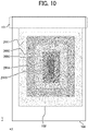
- FIG. 10 is a diagram illustrating a modification of the gradation range described above.
- the gradation range of from 71 to 99 is classified into a gradation range class "A.”
- the two gradation ranges of from 51 to 70 and from 31 to 50 are collectively classified into a gradation range class "B.”
- the two gradation ranges of from 11 to 30 and from 0 to 10 are collectively classified into a gradation range class "C.”
- the present example illustrated in FIG. 10 is different from the example illustrated in FIG. 9 in the gradation ranges for the areas in the gradation range class "B." Specifically, the gradation range for the second area in FIG. 9 is for the third area in FIG. 10 . Similarly, the gradation range for the third area in FIG. 9 is for the second area in FIG. 10 . In other words, as illustrated in FIG. 10 , the second area 2002 having a higher density than the density of the third area 2003 is located outside the third area 2003. Specifically, the patches are located as presented in Table 2 below. Table 2 AREA GRADATION RANGE CLASS GRADATION RANGE FIRST AREA A 71 TO 99 SECOND AREA B 31 TO 50 THIRD AREA 51 TO 70 FOURTH AREA C 11 TO 30 FIFTH AREA 0 TO 10
- Table 2 above is different from Table 1 above in that the gradation range for the second area (presented in the second row from the top in Table 2) and the gradation range for the third area (presented in the third row from the top in the Table 2) are replaced with each other. As described above, the gradation ranges may be replaced with each other in the same gradation range class.
- the gradation range class is not limited to the setting as presented in Table 2. For example, three or more areas may belong to one gradation range class.
- the second portion 102 may be segmented into 6 or more areas. Alternatively, the second portion 102 may be segmented into less than five areas.
- the "gradation area class" may not be set. In a case in which the "gradation area class" is set, the gradation ranges in different gradation range classes may be replaced with each other.
- the location of patches is not limited to the location according to the CMYK-based density, which is a value determined on a cyan, magenta, yellow, and black (CMYK) basis.
- the order of the reference patch 201 and other patches may be determined according to a color space of L ⁇ a ⁇ b ⁇ , which may be referred to as Lab in the following description.
- the order of the reference patch 201 and other patches may be determined according to the Lab-based luminance, which is a value determined on an L ⁇ a ⁇ b ⁇ (Lab) basis.
- the "Lab” is a color space defined by the Commission internationale de l'eclairage (CIE) standard.
- the order of the reference patch 201 and other patches may be determined according to the luminance in the Lab color space.
- patches including the reference patch 201 and may be referred to collectively as a patch in the following description
- shape of patches is not limited to square.
- the patch may be shaped as described below.
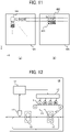
- FIG. 11 is a diagram illustrating a modification of the patch.
- part (a) of FIG. 11 illustrates an example in which all patches have a square shape.
- part (b) of FIG. 11 illustrates an example including a patch having a rectangular shape.
- the patches may include, e.g., a vertically long patch 401 (i.e., a patch elongated in the ⁇ -axis direction in FIG. 11 ) or a laterally long patch 402 (i.e., a patch elongated in the X-axis direction in FIG. 11 ).
- the patch that is used for calibration may have any shape provided that the patch has a certain area.
- the shape of the patch is not limited to square and may be other shapes such as rectangle.
- the patches may have a common shape or different shapes. Preferably, however, the patches have identical areas as much as possible.
- the patches are more freely located.
- locating an elongated patch reduces the number of patches located at the outer circumferential positions of the second portion 102.
- the reference patch 201 and other patches preferably have identical areas and have different shapes.
- the image forming apparatus has a hardware configuration described below, for example.
- FIG. 12 is a block diagram illustrating a hardware configuration of an image forming apparatus 10.
- the image forming apparatus 10 includes a control device 11, a writing device 12, an image forming device 13, an intermediate transfer belt 14, a secondary transfer device 15, a fixing device 16, and a reading device 17.
- the control device 11 is, e.g., an arithmetic device provided with a storage device.
- the control device 11 controls, e.g., the writing device 12 to control image formation.
- the writing device 12, the image forming device 13, the intermediate transfer belt 14, the secondary transfer device 15, and the fixing device 16 perform the image formation according to, e.g., input image data. Specifically, in a case in which an image represented by image data is formed on the sheet 100, a latent image generated according to the image data is developed into a visible toner image, which is transferred onto the intermediate transfer belt 14. The secondary transfer device 15 transfers the toner image from the intermediate transfer belt 14 onto the sheet 100. The fixing device 16 heats the sheet 100 bearing the toner image to fix the toner image onto the sheet 100. In the case of duplex printing on the sheet 100, such a series of image forming operations is performed on both sides of the sheet 100.
- the reading device 17 is, e.g., an optical sensor. Specifically, the reading device 17 reads, e.g., a pattern image for calibration formed on the sheet 100 and generates, e.g., image data. Calibration is performed based on, e.g., the image data thus generated.
- the image forming apparatus 10 may have a configuration as described below, for example.
- FIG. 13 is a block diagram illustrating a first modification of the hardware configuration of the image forming apparatus 10 described above.
- the hardware configuration illustrated in FIG. 13 is different from the hardware configuration illustrated in FIG. 12 in that two reading devices 17 are disposed. Alternatively, three or more reading devices 17 may be disposed.
- the reading devices 17 may be constructed of the reading device 17 that reads a front side of the sheet 100 and the reading device 17 that reads a back side of the sheet 100.
- the image forming apparatus 10 may have a configuration as described below, for example.
- FIG. 14 is a block diagram illustrating a second modification of the hardware configuration of the image forming apparatus 10 described above.
- the reading devices 17 may be located as illustrated in FIG. 14 .
- a gradation characteristic (e.g., a characteristic indicated by a ⁇ correction curve) is adjusted based on data of the color chart 1000 optically read.
- One or more embodiments of the present disclosure may be applied to an image forming system that includes an apparatus or device in addition to the image forming apparatus 10.
- the image forming apparatus 10 and the reading device 17 may be separated from each other as described below.
- FIG. 15 is a diagram illustrating a configuration of an image forming system 20.
- the image forming system 20 is a system that includes a combination of the image forming apparatus 10 and the reading device 17, which is an external device independent of and separate from the image forming apparatus 10.
- the image forming apparatus 10 illustrated in FIG. 15 is different from the image forming apparatuses 10 illustrated in FIGS. 13 and 14 in that the image forming apparatus 10 illustrated in FIG. 15 does not include the reading device 17.
- the reading device 17 is, e.g., a so-called colorimeter.
- the reading devices 17 includes, e.g., a sensor 21 and a sensor control device 22.
- the sensor 21 serves as a reading unit that reads the color chart 1000.
- the sensor control device 22 serves as an output unit that outputs data of the color chart 1000 read by the sensor 21 to the image forming apparatus 10 that forms an image on a recording medium.
- the image forming apparatus 10 forms a test chart on the sheet 100. Thereafter, the reading device 17 reads the test chart. Specifically, the sheet 100 ejected from the image forming apparatus 10 is manually inserted into the reading device 17, for example. Then, the reading device 17 reads the test chart on the sheet 100 and inputs the read data to the image forming apparatus 10.
- the calibration may be performed with a plurality of devices, as in the present example in which an external device reads the test chart. In other words, the number and types of apparatuses or devices are not limited provided that the calibration is performed in a configuration as described below, for example.
- FIG. 16 is a diagram illustrating a configuration for performing calibration.
- the image forming apparatus 10 forms an image of, e.g., the color chart 1000 on the sheet 100 for calibration.
- the reading device 17 such as a colorimeter reads the color chart 1000.
- an information processing apparatus 30 such as a personal computer (PC) calculates a characteristic value.
- the calibration may be performed with the settings of the image forming apparatus 10 updated to conform to the characteristic value thus obtained.
- the image forming apparatus may be an image forming apparatus other than an electrophotographic image forming apparatus.
- the image forming apparatus may be an inkjet image forming apparatus.
- the image forming apparatus may have a hardware configuration including hardware components other than the hardware components described above.
- the calibration is performed in a procedure described below, for example.
- FIG. 17 is a flowchart of an overall process.
- the overall process is performed by the image forming apparatus 10 described above with reference to FIG. 12 .
- the following will describe an example in which the image forming apparatus 10 including the reading device 17 together with the other devices performs the overall process.
- step S1701 the image forming apparatus 10 sets a recording medium. Specifically, a user inputs information of the sheet 100 that is used for calibration, to the image forming apparatus 10.
- step S 1702 the image forming apparatus 10 sets a patch.
- the image forming apparatus 10 determines, e.g., the color of the reference patch 201, the location of patches, and the number of patches, according to the color of the recording medium.
- the configuration of the color chart 1000 is determined.
- the image forming apparatus 10 may set, e.g., the location of the reference patch 201 to identify data based on the reference patch 201 from the read data.
- step S 1703 the image forming apparatus 10 generates a pattern image.
- step S 1704 the image forming apparatus 10 forms a pattern image. Specifically, the image forming apparatus 10 forms a pattern image on the recording medium, thus creating the color chart 1000 including the pattern image.
- step S 1705 the image forming apparatus 10 performs reading.
- step S 1706 the image forming apparatus 10 generates read data.
- the image forming apparatus 10 generates read data indicating, e.g., patch information as data for calibration.
- step S1707 the image forming apparatus 10 updates, e.g., the characteristic value according to the read data, thus performing adjustment.
- the overall process is not limited to the subject, content, and order described above.
- an apparatus or a device other than the image forming apparatus 10 described above may perform the process.
- An operation other than the operations described above may be performed.
- FIG. 18 is a block diagram illustrating a functional configuration of the image forming apparatus 10.
- the image forming apparatus 10 includes, as functional units, a reading unit 10F1, a control unit 10F2, an image forming unit 10F3, and a setting unit 10F4.
- the reading unit 10F1 performs a reading procedure to read the color chart 1000.
- the reading unit 10F1 is implemented by the reading device 17.
- the control unit 10F2 performs a control procedure to perform calibration, based on data of the color chart 1000 read by the reading unit 10F1.
- the control unit 10F2 is implemented by the control device 11.
- the image forming unit 10F3 performs an image forming procedure to form an image in a state adjusted according to a result of the calibration performed by the control unit 10F2.
- the image forming unit 10F3 is implemented by the writing device 12, the image forming device 13, the intermediate transfer belt 14, the secondary transfer device 15, and the fixing device 16.
- the setting unit 10F4 performs a setting procedure to set a position of, e.g., the reference patch 201 in the color chart 1000.
- the setting unit 10F4 is implemented by the reading device 17 or an input device.
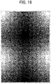
- FIG. 19 is a diagram illustrating a first comparative example.
- the color chart illustrated in FIG. 19 has a relatively large difference in gradation between the patches and the background color.
- FIG. 20 is a diagram illustrating a second comparative example.
- the color chart illustrated in FIG. 20 has a relatively large difference in gradation between the patches and the background color.
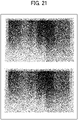
- FIG. 21 is a diagram illustrating a third comparative example.
- FIG. 21 illustrates an image of a color chart formed in gradation from dark to light of various colors such as yellow, magenta, cyan, black, green, and brown.
- the flare affects reading of the color charts.
- the color, location, size, and shape of patches constructing the color chart 1000 and the ratio between the patches and the margin are not limited to the examples described above.
- the intermediate color may be other than red.
- the intermediate color is a color having a density between a color having the highest density (e.g., black) and a color having the lowest density (e.g., white).
- the recording medium is, e.g., a sheet such as a sheet of plain paper.
- examples of the recording medium include, but are not limited to, coated paper, label paper, an overhead projector sheet, a film, and a flexible thin plate.
- the recording medium (or a recording medium that is used for an inkjet image forming apparatus) is made of a material to which ink droplets are at least temporarily adherable, a material to which ink droplets adheres and fixes, or a material to which ink droplets adheres and permeate.
- the recording medium is made of any material to which liquid is adherable, such as paper, thread, fiber, fabric, leather, metal, plastic, glass, wood, ceramic, or a combination thereof.
- a recording material or formation made of such a material include, but are not limited to, a recording medium such as a sheet, a film, or cloth, an electronic component such as an electronic substrate or a piezoelectric element (which may be referred to as a piezoelectric component), layered powder, an organ model, and a testing cell.
- a recording medium such as a sheet, a film, or cloth
- an electronic component such as an electronic substrate or a piezoelectric element (which may be referred to as a piezoelectric component)
- layered powder such as an organ model, and a testing cell.
- the image quality is enhanced.
- the present invention can be implemented in any convenient form, for example using dedicated hardware, or a mixture of dedicated hardware and software.
- the present invention may be implemented as computer software implemented by one or more networked processing apparatuses.
- the processing apparatuses include any suitably programmed apparatuses such as a general purpose computer, a personal digital assistant, a Wireless Application Protocol (WAP) or third-generation (3G)-compliant mobile telephone, and so on. Since the present invention can be implemented as software, each and every aspect of the present invention thus encompasses computer software implementable on a programmable device.
- the computer software can be provided to the programmable device using any conventional carrier medium (carrier means).
- the carrier medium includes a transient carrier medium such as an electrical, optical, microwave, acoustic or radio frequency signal carrying the computer code.
- transient medium is a Transmission Control Protocol/Internet Protocol (TCP/IP) signal carrying computer code over an IP network, such as the Internet.
- the carrier medium may also include a storage medium for storing processor readable code such as a floppy disk, a hard disk, a compact disc read-only memory (CD-ROM), a magnetic tape device, or a solid state memory device.
Landscapes
- Engineering & Computer Science (AREA)
- Multimedia (AREA)
- Signal Processing (AREA)
- Color Image Communication Systems (AREA)
- Facsimile Image Signal Circuits (AREA)
- Accessory Devices And Overall Control Thereof (AREA)
- Spectrometry And Color Measurement (AREA)
- Image Processing (AREA)
- Color, Gradation (AREA)
Abstract
Description
- Embodiments of the present disclosure relate to a color chart, an image forming apparatus, and a reading device.
- There is known a technique of performing, with a color chart, quality adjustment, particularly color reproduction density adjustment, on an image forming apparatus. Such a color chart includes patches in colors reproducible by the image forming apparatus. The image forming apparatus forms an image of the color chart on a recording medium and outputs the recording medium bearing the color chart. The color chart on the recording medium thus output is measured by, e.g., a colorimeter. A color conversion profile is generated based on data of the color chart thus measured.
- Specifically, a plurality of color patches is located such that the rate of the color reproduction density changes at a constant rate. In other words, the color patches in close tones are located adjacent to each other. For example,
Japanese Unexamined Patent Application Publication No. 2012-147411 - However, such a typical technique may cause a relatively large difference in gradation or luminance between the color patches and the background (e.g., a color of a recording medium). Such a relatively large difference may hamper a sufficient reduction of the influence of flare and degrade the image quality.
- In light of the above-described problems, it is a general object of the present invention to provide a color chart that enhances the image quality.
- In order to achieve the above-mentioned object, there is provided a color chart according to
claim 1. Advantageous embodiments are defined by the dependent claims. Advantageously, the color chart includes a first portion and a second portion. The first portion includes no patch. The second portion includes a plurality of patches having different densities or luminances. The plurality of patches includes a reference patch indicating a color having a reference density or luminance. The reference patch is adjacent to the first portion. The plurality of patches is located in order of increasing density from the density of the color indicated by the reference patch, decreasing density from the density of the color indicated by the reference patch, increasing luminance from the luminance of the color indicated by the reference patch, or decreasing luminance from the luminance of the color indicated by the reference patch. - Accordingly, the image quality is enhanced.
- A more complete appreciation of the disclosure and many of the attendant advantages and features thereof can be readily obtained and understood from the following detailed description with reference to the accompanying drawings, wherein:
-
FIG. 1 is a diagram illustrating a color chart according to an embodiment of the present disclosure; -
FIG. 2 is a diagram illustrating an example of location of patches according to an embodiment of the present disclosure; -
FIG. 3 is a diagram illustrating a modification of the location of patches ofFIG. 2 ; -
FIG. 4 is a diagram illustrating a color chart on a black recording medium according to an embodiment of the present disclosure; -
FIG. 5 is a diagram illustrating a color chart including a plurality of portions in which pattern images are formed, according to an embodiment of the present disclosure; -
FIG. 6 is a diagram illustrating an example of location of a reference patch according to an embodiment of the present disclosure; -
FIG. 7 is a diagram illustrating an example of location of the reference patch ofFIG. 6 on a black recording medium; -
FIG. 8 is a diagram illustrating an example of location of the reference patch ofFIG. 6 on a recording medium in an intermediate color; -
FIG. 9 is a diagram illustrating a gradation range according to an embodiment of the present disclosure; -
FIG. 10 is a diagram illustrating a modification of the gradation range ofFIG. 9 ; -
FIG. 11 is a diagram illustrating a modification of a patch according to an embodiment of the present disclosure; -
FIG. 12 is a block diagram illustrating a hardware configuration of an image forming apparatus according to an embodiment of the present disclosure; -
FIG. 13 is a block diagram illustrating a first modification of the hardware configuration of the image forming apparatus ofFIG. 12 ; -
FIG. 14 is a block diagram illustrating a second modification of the hardware configuration of the image forming apparatus ofFIG. 12 ; -
FIG. 15 is a diagram illustrating a configuration of an image forming system according to an embodiment of the present disclosure; -
FIG. 16 is a diagram illustrating a configuration for performing calibration according to an embodiment of the present disclosure; -
FIG. 17 is a flowchart of an overall process according to an embodiment of the present disclosure; -
FIG. 18 is a block diagram illustrating a functional configuration of an image forming apparatus according to an embodiment of the present disclosure; -
FIG. 19 is a diagram illustrating a first comparative example; -
FIG. 20 is a diagram illustrating a second comparative example; and -
FIG. 21 is a diagram illustrating a third comparative example. - The accompanying drawings are intended to depict embodiments of the present invention and should not be interpreted to limit the scope thereof. The accompanying drawings are not to be considered as drawn to scale unless explicitly noted. Also, identical or similar reference numerals designate identical or similar components throughout the several views.
- In describing embodiments illustrated in the drawings, specific terminology is employed for the sake of clarity. However, the disclosure of this specification is not intended to be limited to the specific terminology so selected and it is to be understood that each specific element includes all technical equivalents that have a similar function, operate in a similar manner, and achieve a similar result. As used herein, the singular forms "a," "an," and "the" are intended to include the plural forms as well, unless the context clearly indicates otherwise.
- In a later-described comparative example, embodiment, and exemplary variation, for the sake of simplicity, like reference numerals are given to identical or corresponding constituent elements such as parts and materials having the same functions, and redundant descriptions thereof are omitted unless otherwise required.
- It is to be noted that, in the following description, suffixes Y, M, C, and K (or Bk) denote colors of yellow, magenta, cyan, and black, respectively. To simplify the description, these suffixes are omitted unless necessary.
- Referring to the drawings, wherein like reference numerals designate identical or corresponding parts throughout the several views, embodiments of the present disclosure are described below.
- Initially, a description is given of a first embodiment of the present disclosure.
- A color chart is used for, e.g., calibration for adjusting the color reproduction density of image formation performed by an image forming apparatus. Accordingly, the color chart may be referred to as a calibration chart. The color chart has a configuration as described below, for example.
-
FIG. 1 is a diagram illustrating an example of acolor chart 1000. - For example, an image including a plurality of patches is formed on a
sheet 100 serving as a recording medium. Thus, thecolor chart 1000 is created. Note that such an image including a plurality of patches may be referred to as a pattern image in the following description. - The patch is an image in preset color, density, and shape. The image serving as the patch is set according to calibration. In other words, the image serving as the patch is not limited to an image in specific color, density, and shape. Similarly, e.g., the combination, number, and size of the patches constructing the
color chart 1000 are set in advance according to calibration. - In the present example illustrated in
FIG. 1 , thecolor chart 1000 includes afirst portion 101 and asecond portion 102. Thefirst portion 101 indicates an area in which no pattern image is formed. By contrast, thesecond portion 102 indicates an area in which a pattern image is formed. In other words, thefirst portion 101 includes no patch; whereas thesecond portions 102 includes a plurality of patches. - In the present example, the
sheet 100 is white.FIG. 1 illustrates boundaries with dotted lines. Alternatively, the boundaries may be indicated by no line. - As in the example illustrated in
FIG. 1 , thefirst portion 101 is, e.g., a so-called margin without a pattern image. Thefirst portion 101 has a color of thesheet 100. In other words, thefirst portion 101 has a background color. - As in the example illustrated in
FIG. 1 , thesecond portion 102 is a portion in which patches are located such that the density increases in order from areference patch 201 that is located at a portion adjacent to thefirst portion 101. In short, thereference patch 201 is adjacent to thefirst portion 101. Thereference patch 201 is one of the outermost patches in thesecond portion 102. - In the present example, the
reference patch 201 is the lowest density patch in thesecond portion 102. In the present example, the highest density patch in thesecond portion 102 is alast patch 202 located at a central portion of thesecond portion 102. - For example, the patches are located such that the density increases from the
reference patch 201 toward the last patch 202 (in the order indicated by arrow inFIG. 1 ). In the present example, the density decreases outward and increases inward to the central portion of thesecond portion 102. In a case in which thesheet 100 is white as in the present example, thereference patch 201 is preferably white or in a color having a density close to the color of thesheet 100. - As indicated by arrow in
FIG. 1 , for example, the patches are located in a spiral shape toward the central portion of thesecond portion 102. Specifically, the patches are located in the order described below. -
FIG. 2 is a diagram illustrating an example of location of patches. - Now, a description is given of an example in which the
color chart 1000 includes 16 patches.FIG. 2 illustrates the order in which the patches are located by numbers.FIG. 2 also illustrates the order of increasing density by a dotted arrow. - Specifically, the patches are located such that the density increases in order from the portion indicated by "1" to the portion indicated by "16." In short, the highest density patch (e.g., the last patch 202) is located at the portion indicated by "16"; whereas the lowest density patch (e.g., the reference patch 201) is located at the portion indicated by "1." In the
color chart 1000 of the present example, the density of the patches increases as the number increases, from the lightest patch located at the portion indicated by "1" to the darkest patch located at the portion indicated by "16." - The number of patches is not limited to 16. The number of patches may be increased to finely change the density of the patches. By contrast, the number of patches may be less than 16.
- As described above, preferably, patches in a color having a density close to the color of the
sheet 100 are located at portions adjacent to thefirst portion 101, such as the portions indicated by "1" to "4." In addition, preferably, the patches are located such that the density increases toward an inner portion such as a portion indicated by "15" or "16." - Such a location of the patches reduces the difference in gradation between adjacent patches such as patches "1" and "2" (i.e., the patches located at the portions indicated by "1" and "2").
- Alternatively, the patches may be located as described below, for example.
-
FIG. 3 is a diagram illustrating a modification of the location of the patches ofFIG. 2 . - The location illustrated in
FIG. 3 is different from the location illustrated inFIG. 2 in that the order of patches "10" and "11" (i.e., the patches located at the portions indicated by "10" and "11") are reversed. In other words, the patches may not be located in order of completely increasing density. - Specifically, provided that the difference in gradation between adjacent patches is relatively small, such as a combination of patches "10" and "11", a combination of patches "10" and "12" (i.e., the patches located at the portions indicated by "10" and "12"), and a combination of patches "11" and "9" (i.e., the patches located at the portions indicated by "11" and "9"), the patches may not be located in the order of completely increasing density.
- Whether the difference in gradation is relatively small is determined by, e.g., whether the difference in gradation is equal to or greater than a preset value. In short, the
color chart 1000 includes patches located such that patches having a relatively small difference in gradation less than the preset value are adjacent to each other. - The
color chart 1000 including the patched located as described above reduces the difference in gradation between the color of thesheet 100 and the color of outer circumferential patches of thesecond portion 102 such as thereference patch 201. In short, such a color chart reduces the influence of flare in calibration. Reducing the influence of flare enhances the color reproducibility and the image quality in image formation. With the configuration described above, the number of patches is not to be reduced. - When a reading device reads a color chart in calibration, the reading device may capture reflected light entering from the periphery of target patches, thus causing the flare. As the difference in gradation between the color of patches and the color of the
sheet 100 is larger, the detected data is more likely to deviate from the true value due to the influence of the flare. To prevent such a situation, preferably, thereference patch 201 as a patch located at a portion adjacent to the portion in the color of thesheet 100 has the same density as the color of thesheet 100 or a density close to the color of thesheet 100. When the patches are located such that the density increases in order starting from thereference patch 201, a patch having a relatively low density in theentire color chart 1000 may be located at a portion in the color of thesheet 100 or having a density close to the color of thesheet 100. In short, the difference in the density between e.g., thereference patch 201 and the color of the recording medium is preferably equal to or less than a given value. - A description is now given of a second embodiment of the present disclosure.
- The second embodiment is different from the first embodiment in that the color of the
sheet 100 is black, for example. In other words, in the second embodiment, the color of thefirst portion 101 in which no pattern image exists is black. - The
reference patch 201 is preferably changed according to the color of the recording medium. Specifically, when the color of thesheet 100 is black as in the second embodiment, thereference patch 201 is preferably changed as follows. -
FIG. 4 is a diagram illustrating an example of thecolor chart 1000 on a black recording medium. - In the present example, the patches are located such that the density of the patches increases outward and decreases inward. In a case in which the
sheet 100 is black as in the present example, thereference patch 201 is preferably black or in a color having a density close to the color of thesheet 100. As described above, preferably, thereference patch 201 is changed according to the color of thesheet 100, to a color having the same density as the color of thesheet 100 or a color having a density close to the color of thesheet 100. The patches are located such that the density decreases in order from thereference patch 201 toward thelast patch 202. - Although the color of the
sheet 100 is white in the first embodiment, the color of thesheet 100 is not limited to white. As in the second embodiment, the color of thesheet 100 may be black. Alternatively, the color of thesheet 100 may be an intermediate color. The intermediate color is, e.g., red. - In a case in which the
sheet 100 is in an intermediate color, thecolor chart 1000 may include a plurality ofsecond portions 102, for example. Now, a description is given of an example in which thecolor chart 1000 includes two second portions (each corresponding to the second portion 102). -
FIG. 5 is a diagram illustrating an example of thecolor chart 1000 including two second portions (each corresponding to the second portion 102). - In the present example, the color of the
sheet 100 is red. InFIG. 5 , the hatched portion is thefirst portion 101 as a portion in a background color. - For example, the two second portions are vertically located, one by one, in the Y direction in
FIG. 5 . In the present example, the two second portions are referred to as anupper portion 1022 and alower portion 1021. Theupper portion 1022 is a second portion disposed above; whereas thelower portion 1021 is a second portion disposed below. - The
upper portion 1022 includes patches located in a spiral shape such that the density decreases inward in order from afirst reference patch 2011, which is located at the upper left in theupper portion 1022, to a firstlast patch 2021, which is the lightest patch located at the center of theupper portion 1022. On the other hand, thelower portion 1021 includes patches located in a spiral shape such that the density increases inward in order from asecond reference patch 2012, which is located at the upper left in thelower portion 1021, to a secondlast patch 2022, which is the darkest patch located at the center of thelower portion 1021. -
FIG. 5 illustrates thefirst reference patch 2011, thesecond reference patch 2012, and thefirst portion 101 in different colors for the sake of description. Preferably, thefirst reference patch 2011, thesecond reference patch 2012, and thefirst portion 101 are in a color having densities close to each other. - As in the present example, the
color chart 1000 may include two second portions: a second portion in which patches are located such that the density decreases from thefirst reference patch 2011 to the firstlast patch 2021 as in theupper portion 1022, and a second portion in which patches are located such that the density increases from thesecond reference patch 2012 to the secondlast patch 2022 as in thelower portion 1021. - In particular, in a case in which an intermediate color is used, both the location of patches in which the density sequentially increases and the location of patches in which the density sequentially decreases may be used for calibration. In a case in which the recording medium is in an intermediate color, the density of the reference patch is an intermediate value. In other words, either the location of patches in which the density increases or the location of patches in which the density decreases may be insufficient to acquire all the densities, resulting in generation of insufficient calibration data. By contrast, as in the above-described example in which the
color chart 1000 includes a plurality of second portions, the color reproduction is enhanced by calibration with calibration data acquired, even in a case in which the recording medium is in an intermediate color. - The example described above is an example in which the two second portions (i.e., the
upper portion 1022 and the lower portion 1021) are equal to each other. Alternatively, theupper portion 1022 and thelower portion 1021 may not be equal to each other. Specifically, the ratio in number between the patches located in theupper portion 1022 and the patches located in thelower portion 1021 in the example described above is preferably adjusted depending on the intermediate color. For example, in a case in which thesheet 100 is in an intermediate and dark color, the patches located in thelower portion 1021 is less in number or ratio than the patches located in theupper portion 1022. Thus, e.g., the number of patches in the plurality of second portions is preferably adjusted according to the density of the intermediate color. - Now, a detailed description is given of the
reference patch 201. - The
reference patch 201 is located as described below. -
FIG. 6 is a diagram illustrating an example of location of thereference patch 201. - In the present example, the
sheet 100 is white. For example, thereference patch 201 is located anywhere in an outer circumferential portion (e.g., an outermostcircumferential portion 103 inFIG. 6 ) of thesecond portion 102. As illustrated inFIG. 6 , the outermostcircumferential portion 103 may be a pattern image. On the other hand, patches may be or may not be located in aninner portion 104, which is a portion inside the outermostcircumferential portion 103 and illustrated as a hatched portion inFIG. 6 . In other words, theinner portion 104 may be blank without a pattern image or may include any image. For the sake of description, theinner portion 104 is hatched inFIG. 6 . However, theinner portion 104 is not hatched in actuality. - As described above, locating the
reference patch 201 in the outermostcircumferential portion 103 reduces the difference in gradation between the color of the patches and the color of thesheet 100. Specifically, such a location attains a difference in gradation of about 30% or less. Accordingly, the influence of flare is reduced. - As in the second embodiment, the color of the
sheet 100 may be, e.g., black or an intermediate color as described below. -
FIG. 7 is a diagram illustrating an example of location of thereference patch 201 on a black recording medium. - In a case in which the
sheet 100 is black as illustrated inFIG. 7 , thereference patch 201 is set to a color close to black. As described above with reference toFIG. 6 , patches may be or may not be located in theinner portion 104. -
FIG. 8 is a diagram illustrating an example of location of thereference patch 201 on a recording medium in an intermediate color. - In a case in which the
sheet 100 is an intermediate color such as red as illustrated inFIG. 8 , the color of thereference patch 201 is set to a color having a density, which is luminance in a modification described later, close to the color of the background. As described above with reference toFIG. 6 , patches may be or may not be located in theinner portion 104. - Now, a description is given of an example of location of patches.
- For example, the patches are located in gradation described below.
-
FIG. 9 is a diagram illustrating a gradation range. - As illustrated in
FIG. 9 , in the present example, thesecond portion 102 is segmented into 5 areas inward: afirst area 2001, asecond area 2002, athird area 2003, afourth area 2004, and afifth area 2005. - The gradation has 100 tones from 0 to 99 in the present example. For each of the first to
fifth areas 2001 to 2005, the gradation range, which is a range of tones of patches, is set in advance. In the present example, a higher tone indicates a lighter color close to white. For example, the gradation range is set as presented in Table 1 for each of the first tofifth areas 2001 to 2005.Table 1 AREA GRADATION RANGE CLASS GRADATION RANGE FIRST AREA A 71 TO 99 SECOND AREA B 51 TO 70 THIRD AREA 31 TO 50 FOURTH AREA C 11 TO 30 FIFTH AREA 0 TO 10 - As presented in Table 1 above, patches in tones from 71 to 99 are located in the
first area 2001, which is adjacent to thefirst portion 101. Also as presented in Table 1 above, patches in tones smaller than tones of the patches located in thefirst area 2001 and greater than tones of patches located in thethird area 2003 are located in thesecond area 2002. - Similarly, the patches in tones smaller than the tones of the patches located in the
second area 2002 and greater than tones of patches located in thefourth area 2004 are located in thethird area 2003. The patches in tones smaller than the tones of the patches located in thethird area 2003 and greater than tones of patches located in thefifth area 2005 are located in thefourth area 2004. Lastly, the patches in tones smaller than the tones of the patches located in thefourth area 2004 are located in thefifth area 2005. As described above, the patches are preferably located such that the density increases (in other words, the tones indicated in the column of "gradation range" in Table 1 decreases) inward in the first tofifth areas 2001 to 2005. - More preferably, such a location reduces a difference in gradation between the patches and the background and a difference in gradation between adjacent patches.
- The location of the patches is not limited to the example presented in Table 1, provided that the difference in gradation between the patches and the background and the difference in gradation between the adjacent patches are within a certain range. For example, the following combination of "gradation range" and "area" may be used.
-
FIG. 10 is a diagram illustrating a modification of the gradation range described above. - In the present example, as presented in Table 1 above, the gradation range of from 71 to 99 is classified into a gradation range class "A." The two gradation ranges of from 51 to 70 and from 31 to 50 are collectively classified into a gradation range class "B." Further, the two gradation ranges of from 11 to 30 and from 0 to 10 are collectively classified into a gradation range class "C."
- The present example illustrated in
FIG. 10 is different from the example illustrated inFIG. 9 in the gradation ranges for the areas in the gradation range class "B." Specifically, the gradation range for the second area inFIG. 9 is for the third area inFIG. 10 . Similarly, the gradation range for the third area inFIG. 9 is for the second area inFIG. 10 . In other words, as illustrated inFIG. 10 , thesecond area 2002 having a higher density than the density of thethird area 2003 is located outside thethird area 2003. Specifically, the patches are located as presented in Table 2 below.Table 2 AREA GRADATION RANGE CLASS GRADATION RANGE FIRST AREA A 71 TO 99 SECOND AREA B 31 TO 50 THIRD AREA 51 TO 70 FOURTH AREA C 11 TO 30 FIFTH AREA 0 TO 10 - Table 2 above is different from Table 1 above in that the gradation range for the second area (presented in the second row from the top in Table 2) and the gradation range for the third area (presented in the third row from the top in the Table 2) are replaced with each other. As described above, the gradation ranges may be replaced with each other in the same gradation range class.
- The gradation range class is not limited to the setting as presented in Table 2. For example, three or more areas may belong to one gradation range class.
- Setting the gradation range and setting the areas are not limited to the examples described above with reference to Table 1. For example, the
second portion 102 may be segmented into 6 or more areas. Alternatively, thesecond portion 102 may be segmented into less than five areas. Optionally, the "gradation area class" may not be set. In a case in which the "gradation area class" is set, the gradation ranges in different gradation range classes may be replaced with each other. - Now, a description is given of a modification.
- The location of patches is not limited to the location according to the CMYK-based density, which is a value determined on a cyan, magenta, yellow, and black (CMYK) basis. For example, the order of the
reference patch 201 and other patches may be determined according to a color space of L∗a∗b∗, which may be referred to as Lab in the following description. In other words, the order of thereference patch 201 and other patches may be determined according to the Lab-based luminance, which is a value determined on an L∗a∗b∗ (Lab) basis. - The "Lab" is a color space defined by the Commission internationale de l'eclairage (CIE) standard.
- The order of the
reference patch 201 and other patches may be determined according to the luminance in the Lab color space. - The shape of patches (including the
reference patch 201 and may be referred to collectively as a patch in the following description) is not limited to square. For example, the patch may be shaped as described below. -
FIG. 11 is a diagram illustrating a modification of the patch. - For comparison, part (a) of
FIG. 11 illustrates an example in which all patches have a square shape. - By contrast, part (b) of
FIG. 11 illustrates an example including a patch having a rectangular shape. Specifically, the patches may include, e.g., a vertically long patch 401 (i.e., a patch elongated in the γ-axis direction inFIG. 11 ) or a laterally long patch 402 (i.e., a patch elongated in the X-axis direction inFIG. 11 ). - The patch that is used for calibration may have any shape provided that the patch has a certain area. In other words, the shape of the patch is not limited to square and may be other shapes such as rectangle. The patches may have a common shape or different shapes. Preferably, however, the patches have identical areas as much as possible.
- In a case in which one or more patches are shaped as, e.g., rectangle, the patches are more freely located. For example, locating an elongated patch reduces the number of patches located at the outer circumferential positions of the
second portion 102. In short, thereference patch 201 and other patches preferably have identical areas and have different shapes. - Now, a description is given of an image forming apparatus according to an embodiment of the present disclosure.
- The image forming apparatus has a hardware configuration described below, for example.
-
FIG. 12 is a block diagram illustrating a hardware configuration of animage forming apparatus 10. - For example, the
image forming apparatus 10 includes acontrol device 11, awriting device 12, animage forming device 13, anintermediate transfer belt 14, asecondary transfer device 15, a fixingdevice 16, and areading device 17. - The
control device 11 is, e.g., an arithmetic device provided with a storage device. Thecontrol device 11 controls, e.g., thewriting device 12 to control image formation. - The
writing device 12, theimage forming device 13, theintermediate transfer belt 14, thesecondary transfer device 15, and the fixingdevice 16 perform the image formation according to, e.g., input image data. Specifically, in a case in which an image represented by image data is formed on thesheet 100, a latent image generated according to the image data is developed into a visible toner image, which is transferred onto theintermediate transfer belt 14. Thesecondary transfer device 15 transfers the toner image from theintermediate transfer belt 14 onto thesheet 100. The fixingdevice 16 heats thesheet 100 bearing the toner image to fix the toner image onto thesheet 100. In the case of duplex printing on thesheet 100, such a series of image forming operations is performed on both sides of thesheet 100. - The
reading device 17 is, e.g., an optical sensor. Specifically, thereading device 17 reads, e.g., a pattern image for calibration formed on thesheet 100 and generates, e.g., image data. Calibration is performed based on, e.g., the image data thus generated. - Alternatively, the
image forming apparatus 10 may have a configuration as described below, for example. -
FIG. 13 is a block diagram illustrating a first modification of the hardware configuration of theimage forming apparatus 10 described above. - The hardware configuration illustrated in
FIG. 13 is different from the hardware configuration illustrated inFIG. 12 in that tworeading devices 17 are disposed. Alternatively, three ormore reading devices 17 may be disposed. - In other words, the
reading devices 17 may be constructed of thereading device 17 that reads a front side of thesheet 100 and thereading device 17 that reads a back side of thesheet 100. - Alternatively, the
image forming apparatus 10 may have a configuration as described below, for example. -
FIG. 14 is a block diagram illustrating a second modification of the hardware configuration of theimage forming apparatus 10 described above. - The
reading devices 17 may be located as illustrated inFIG. 14 . - In particular, in printing such as production printing, high image quality is often required. In order to satisfy such a requirement, a user performs calibration depending on a change over time, an environmental change, usage conditions, or a combination thereof, thus enhancing the image quality of image formation. In such a case, performing calibration on an image forming apparatus with the
color chart 1000 according to the present embodiment adjusts the characteristics of the image forming apparatus. - In calibration, a gradation characteristic (e.g., a characteristic indicated by a γ correction curve) is adjusted based on data of the
color chart 1000 optically read. - One or more embodiments of the present disclosure may be applied to an image forming system that includes an apparatus or device in addition to the
image forming apparatus 10. For example, theimage forming apparatus 10 and thereading device 17 may be separated from each other as described below. -
FIG. 15 is a diagram illustrating a configuration of animage forming system 20. - For example, the
image forming system 20 is a system that includes a combination of theimage forming apparatus 10 and thereading device 17, which is an external device independent of and separate from theimage forming apparatus 10. - The
image forming apparatus 10 illustrated inFIG. 15 is different from theimage forming apparatuses 10 illustrated inFIGS. 13 and 14 in that theimage forming apparatus 10 illustrated inFIG. 15 does not include thereading device 17. In the present example, thereading device 17 is, e.g., a so-called colorimeter. Thereading devices 17 includes, e.g., asensor 21 and asensor control device 22. Thesensor 21 serves as a reading unit that reads thecolor chart 1000. Thesensor control device 22 serves as an output unit that outputs data of thecolor chart 1000 read by thesensor 21 to theimage forming apparatus 10 that forms an image on a recording medium. - In the
image forming system 20, first, theimage forming apparatus 10 forms a test chart on thesheet 100. Thereafter, thereading device 17 reads the test chart. Specifically, thesheet 100 ejected from theimage forming apparatus 10 is manually inserted into thereading device 17, for example. Then, thereading device 17 reads the test chart on thesheet 100 and inputs the read data to theimage forming apparatus 10. The calibration may be performed with a plurality of devices, as in the present example in which an external device reads the test chart. In other words, the number and types of apparatuses or devices are not limited provided that the calibration is performed in a configuration as described below, for example. -
FIG. 16 is a diagram illustrating a configuration for performing calibration. - For example, as illustrated in
FIG. 16 , first, theimage forming apparatus 10 forms an image of, e.g., thecolor chart 1000 on thesheet 100 for calibration. Then, thereading device 17 such as a colorimeter reads thecolor chart 1000. With the read data output from thereading device 17, aninformation processing apparatus 30 such as a personal computer (PC) calculates a characteristic value. The calibration may be performed with the settings of theimage forming apparatus 10 updated to conform to the characteristic value thus obtained. - According to one or more embodiments of the present disclosure, the image forming apparatus may be an image forming apparatus other than an electrophotographic image forming apparatus. For example, the image forming apparatus may be an inkjet image forming apparatus. The image forming apparatus may have a hardware configuration including hardware components other than the hardware components described above.
- Now, a description is given of an overall process.
- The calibration is performed in a procedure described below, for example.
-
FIG. 17 is a flowchart of an overall process. - In the present example, the overall process is performed by the
image forming apparatus 10 described above with reference toFIG. 12 . In other words, the following will describe an example in which theimage forming apparatus 10 including thereading device 17 together with the other devices performs the overall process. - In step S1701, the
image forming apparatus 10 sets a recording medium. Specifically, a user inputs information of thesheet 100 that is used for calibration, to theimage forming apparatus 10. - In step S 1702, the
image forming apparatus 10 sets a patch. For example, theimage forming apparatus 10 determines, e.g., the color of thereference patch 201, the location of patches, and the number of patches, according to the color of the recording medium. Thus, the configuration of thecolor chart 1000 is determined. Note that theimage forming apparatus 10 may set, e.g., the location of thereference patch 201 to identify data based on thereference patch 201 from the read data. - In step S 1703, the
image forming apparatus 10 generates a pattern image. - In step S 1704, the
image forming apparatus 10 forms a pattern image. Specifically, theimage forming apparatus 10 forms a pattern image on the recording medium, thus creating thecolor chart 1000 including the pattern image. - In step S 1705, the
image forming apparatus 10 performs reading. - In step S 1706, the
image forming apparatus 10 generates read data. In other words, theimage forming apparatus 10 generates read data indicating, e.g., patch information as data for calibration. - In step S1707, the
image forming apparatus 10 updates, e.g., the characteristic value according to the read data, thus performing adjustment. - Note that the overall process is not limited to the subject, content, and order described above. For example, an apparatus or a device other than the
image forming apparatus 10 described above may perform the process. An operation other than the operations described above may be performed. - Now, a description is given of a functional configuration of an image forming apparatus according to an embodiment of the present disclosure.
-
FIG. 18 is a block diagram illustrating a functional configuration of theimage forming apparatus 10. - For example, the
image forming apparatus 10 includes, as functional units, a reading unit 10F1, a control unit 10F2, an image forming unit 10F3, and a setting unit 10F4. - The reading unit 10F1 performs a reading procedure to read the
color chart 1000. For example, the reading unit 10F1 is implemented by thereading device 17. - The control unit 10F2 performs a control procedure to perform calibration, based on data of the
color chart 1000 read by the reading unit 10F1. For example, the control unit 10F2 is implemented by thecontrol device 11. - The image forming unit 10F3 performs an image forming procedure to form an image in a state adjusted according to a result of the calibration performed by the control unit 10F2. For example, the image forming unit 10F3 is implemented by the
writing device 12, theimage forming device 13, theintermediate transfer belt 14, thesecondary transfer device 15, and the fixingdevice 16. - The setting unit 10F4 performs a setting procedure to set a position of, e.g., the
reference patch 201 in thecolor chart 1000. For example, the setting unit 10F4 is implemented by thereading device 17 or an input device. - Now, a description is given of some comparative examples.
- Specifically, a description is now given of three color charts as comparative examples of the
color chart 1000 according to the present embodiment. -
FIG. 19 is a diagram illustrating a first comparative example. - Although the patches are located such that adjacent patches are in close tones, the color chart illustrated in
FIG. 19 has a relatively large difference in gradation between the patches and the background color. -
FIG. 20 is a diagram illustrating a second comparative example. - Although the outer circumferential patches have an area greater than the area of inside patches, the color chart illustrated in
FIG. 20 has a relatively large difference in gradation between the patches and the background color. -
FIG. 21 is a diagram illustrating a third comparative example. -
FIG. 21 illustrates an image of a color chart formed in gradation from dark to light of various colors such as yellow, magenta, cyan, black, green, and brown. - When calibration is performed with the color charts described above as the first to third comparative examples, the flare affects reading of the color charts.
- Now, a description is given of other embodiments of the present disclosure.
- For example, the color, location, size, and shape of patches constructing the
color chart 1000 and the ratio between the patches and the margin are not limited to the examples described above. - The intermediate color may be other than red. In other words, the intermediate color is a color having a density between a color having the highest density (e.g., black) and a color having the lowest density (e.g., white).
- The recording medium is, e.g., a sheet such as a sheet of plain paper. In addition to plain paper, examples of the recording medium include, but are not limited to, coated paper, label paper, an overhead projector sheet, a film, and a flexible thin plate. In other words, the recording medium (or a recording medium that is used for an inkjet image forming apparatus) is made of a material to which ink droplets are at least temporarily adherable, a material to which ink droplets adheres and fixes, or a material to which ink droplets adheres and permeate. In short, the recording medium is made of any material to which liquid is adherable, such as paper, thread, fiber, fabric, leather, metal, plastic, glass, wood, ceramic, or a combination thereof.
- Specific examples of a recording material or formation made of such a material include, but are not limited to, a recording medium such as a sheet, a film, or cloth, an electronic component such as an electronic substrate or a piezoelectric element (which may be referred to as a piezoelectric component), layered powder, an organ model, and a testing cell.
- According to the embodiments of the present disclosure, the image quality is enhanced.
- The above-described embodiments are illustrative and do not limit the present invention. Thus, numerous additional modifications and variations are possible in light of the above teachings. For example, elements and/or features of different illustrative embodiments may be combined with each other and/or substituted for each other within the scope of the present invention.
- Any one of the above-described operations may be performed in various other ways, for example, in an order different from the one described above.
- The present invention can be implemented in any convenient form, for example using dedicated hardware, or a mixture of dedicated hardware and software. The present invention may be implemented as computer software implemented by one or more networked processing apparatuses. The processing apparatuses include any suitably programmed apparatuses such as a general purpose computer, a personal digital assistant, a Wireless Application Protocol (WAP) or third-generation (3G)-compliant mobile telephone, and so on. Since the present invention can be implemented as software, each and every aspect of the present invention thus encompasses computer software implementable on a programmable device. The computer software can be provided to the programmable device using any conventional carrier medium (carrier means). The carrier medium includes a transient carrier medium such as an electrical, optical, microwave, acoustic or radio frequency signal carrying the computer code. An example of such a transient medium is a Transmission Control Protocol/Internet Protocol (TCP/IP) signal carrying computer code over an IP network, such as the Internet. The carrier medium may also include a storage medium for storing processor readable code such as a floppy disk, a hard disk, a compact disc read-only memory (CD-ROM), a magnetic tape device, or a solid state memory device.
Claims (12)
- A color chart (1000) comprising:a first portion (101) including no patch; anda second portion (102) including a plurality of patches having different densities or luminances,the plurality of patches including a reference patch (201) indicating a color having a reference density or luminance,the reference patch (201) being adjacent to the first portion (101),the plurality of patches being located in order of:increasing density from the density of the color indicated by the reference patch (201);decreasing density from the density of the color indicated by the reference patch (201);increasing luminance from the luminance of the color indicated by the reference patch (201); ordecreasing luminance from the luminance of the color indicated by the reference patch (201).
- The color chart (1000) according to claim 1,
wherein the reference patch (201) has a color corresponding to a color of a recording medium. - The color chart (1000) according to claim 1 or 2,
wherein the plurality of patches including the reference patch (201) are located in a spiral shape in the second portion (102). - The color chart (1000) according to claim 3, further comprising another second portion (1021, 1022).
- The color chart (1000) according to any one of claims 1 to 4,
wherein the plurality of patches including the reference patch (201) have identical areas. - The color chart (1000) according to any one of claims 1 to 5,
wherein the plurality of patches including the reference patch (201) have different shapes. - The color chart (1000) according to any one of claims 1 to 6,
wherein the density is a value determined on a cyan, magenta, yellow, and black (CMYK) basis. - The color chart (1000) according to any one of claims 1 to 6,
wherein the luminance is a value determined on an L∗a∗b∗ (Lab) basis. - The color chart (1000) according to any one of claims 1 to 8,
wherein a difference in the density between the reference patch (201) and a color of a recording medium is equal to or less than a given value. - An image forming apparatus (10) comprising:a reading unit (10F1) configured to read the color chart (1000) according to any one of claims 1 to 9;a control unit (10F2) configured to perform calibration, based on data of the color chart (1000) read by the reading unit (10F1);an image forming unit (10F3) configured to form an image, based on a result of the calibration performed by the control unit (10F2); anda setting unit (10F4) configured to set a position of the reference patch (201) in the color chart (1000).
- An image forming apparatus (10) comprising:an image forming unit (10F3) configured to form the color chart (1000) according to any one of claims 1 to 9;a reading unit (10F1) configured to read the color chart (1000) formed by the image forming unit (10F3); anda control unit (10F3) configured to perform calibration, based on data of the color chart (1000) read by the reading unit (10F1),the image forming unit (10F3) being configured to form an image on a recording medium, based on a result of the calibration performed by the control unit (10F2).
- A reading device (17) comprising:a reading unit (21) configured to read the color chart (1000) according to any one of claims 1 to 9; andan output unit (22) configured to output data of the color chart (1000) read by the reading unit (21) to an image forming apparatus (10) configured to form an image on a recording medium.
Applications Claiming Priority (1)
| Application Number | Priority Date | Filing Date | Title |
|---|---|---|---|
| JP2020169067A JP7618994B2 (en) | 2020-10-06 | 2020-10-06 | Image forming device |
Publications (2)
| Publication Number | Publication Date |
|---|---|
| EP3982621A1 true EP3982621A1 (en) | 2022-04-13 |
| EP3982621B1 EP3982621B1 (en) | 2025-01-22 |
Family
ID=77640431
Family Applications (1)
| Application Number | Title | Priority Date | Filing Date |
|---|---|---|---|
| EP21194760.1A Active EP3982621B1 (en) | 2020-10-06 | 2021-09-03 | Color chart, image forming apparatus, and reading device |
Country Status (3)
| Country | Link |
|---|---|
| US (1) | US11539863B2 (en) |
| EP (1) | EP3982621B1 (en) |
| JP (1) | JP7618994B2 (en) |
Families Citing this family (3)
| Publication number | Priority date | Publication date | Assignee | Title |
|---|---|---|---|---|
| JP7775622B2 (en) * | 2021-10-08 | 2025-11-26 | 株式会社リコー | Image reading device and image forming device |
| US12061941B2 (en) * | 2022-05-24 | 2024-08-13 | Canon Kabushiki Kaisha | Image forming system for inspecting quality of image formed on printing medium |
| JP2024110513A (en) | 2023-02-03 | 2024-08-16 | 株式会社リコー | Information processing device, information processing system, information processing method, and program |
Citations (4)
| Publication number | Priority date | Publication date | Assignee | Title |
|---|---|---|---|---|
| EP1081939A2 (en) * | 1999-09-03 | 2001-03-07 | Sharp Kabushiki Kaisha | Image forming apparatus and image processing method used for the same |
| US6750993B1 (en) * | 1999-09-10 | 2004-06-15 | Fuji Photo Film Co., Ltd. | Density calibration chart |
| US20100214581A1 (en) * | 2009-02-24 | 2010-08-26 | Fuji Xerox Co., Ltd. | Image forming apparatus |
| JP2012147411A (en) | 2010-12-24 | 2012-08-02 | Ricoh Co Ltd | Color chart, color chart layout method and image forming apparatus |
Family Cites Families (15)
| Publication number | Priority date | Publication date | Assignee | Title |
|---|---|---|---|---|
| US6018381A (en) * | 1997-01-30 | 2000-01-25 | Eastman Kodak Company | Method for calibrating a photofinishing system and components for use in such a method |
| JPH10278347A (en) * | 1997-04-08 | 1998-10-20 | Canon Inc | Image processing apparatus and method |
| JP2001138608A (en) * | 1999-11-17 | 2001-05-22 | Fuji Photo Film Co Ltd | Method for evaluating continuity |
| JP4472128B2 (en) * | 2000-07-06 | 2010-06-02 | 富士フイルム株式会社 | Density measuring method and image forming apparatus |
| JP2008066923A (en) * | 2006-09-06 | 2008-03-21 | Seiko Epson Corp | Calibration method and image forming apparatus |
| JP4807886B2 (en) * | 2008-03-12 | 2011-11-02 | コニカミノルタビジネステクノロジーズ株式会社 | Calibration system and calibration method |
| JP5484085B2 (en) * | 2010-01-18 | 2014-05-07 | キヤノン株式会社 | Image forming apparatus and image quality correction method thereof |
| JP2012004931A (en) * | 2010-06-18 | 2012-01-05 | Konica Minolta Business Technologies Inc | Print preview apparatus and program |
| JP5958099B2 (en) * | 2011-07-29 | 2016-07-27 | 株式会社リコー | Color measuring device, image forming apparatus and program |
| JP6108817B2 (en) * | 2012-12-20 | 2017-04-05 | キヤノン株式会社 | Image processing apparatus, image processing method, and program for executing image processing method. |
| US9609165B2 (en) | 2014-12-15 | 2017-03-28 | Ricoh Company, Ltd. | Processing image read by overlapping adjacent line sensors by detecting frequency of density variations in seam-read image and synthesizing seam-read images based on detection result to form seam image |
| US9906668B2 (en) | 2014-12-17 | 2018-02-27 | Ricoh Company, Ltd. | Image forming apparatus, front-back magnification correction method, and computer program product |
| JP6451301B2 (en) * | 2014-12-22 | 2019-01-16 | コニカミノルタ株式会社 | Image forming apparatus |
| US10848631B2 (en) | 2018-09-26 | 2020-11-24 | Ricoh Company, Ltd. | Reading device and image forming apparatus |
| JP7400480B2 (en) | 2020-01-14 | 2023-12-19 | 株式会社リコー | Image reading device and image reading method |
-
2020
- 2020-10-06 JP JP2020169067A patent/JP7618994B2/en active Active
-
2021
- 2021-09-03 EP EP21194760.1A patent/EP3982621B1/en active Active
- 2021-09-20 US US17/478,964 patent/US11539863B2/en active Active
Patent Citations (4)
| Publication number | Priority date | Publication date | Assignee | Title |
|---|---|---|---|---|
| EP1081939A2 (en) * | 1999-09-03 | 2001-03-07 | Sharp Kabushiki Kaisha | Image forming apparatus and image processing method used for the same |
| US6750993B1 (en) * | 1999-09-10 | 2004-06-15 | Fuji Photo Film Co., Ltd. | Density calibration chart |
| US20100214581A1 (en) * | 2009-02-24 | 2010-08-26 | Fuji Xerox Co., Ltd. | Image forming apparatus |
| JP2012147411A (en) | 2010-12-24 | 2012-08-02 | Ricoh Co Ltd | Color chart, color chart layout method and image forming apparatus |
Also Published As
| Publication number | Publication date |
|---|---|
| US20220109780A1 (en) | 2022-04-07 |
| US11539863B2 (en) | 2022-12-27 |
| JP7618994B2 (en) | 2025-01-22 |
| JP2022061211A (en) | 2022-04-18 |
| EP3982621B1 (en) | 2025-01-22 |
Similar Documents
| Publication | Publication Date | Title |
|---|---|---|
| EP3982621B1 (en) | Color chart, image forming apparatus, and reading device | |
| JP3314883B2 (en) | Adaptive apparatus and method for providing accurate tone reproduction control in an imaging system | |
| JP4217643B2 (en) | Image density correction method and image density correction system | |
| US20090190194A1 (en) | Color Correction Method for an Imaging System | |
| US8417135B2 (en) | Methods to control appearance of gloss levels for printed text and images | |
| US7477418B2 (en) | Method and system for correcting color rendering devices | |
| EP1156666B1 (en) | Color-balanced TRC correction to compensate for illuminant changes in printer characterization | |
| US20090195797A1 (en) | Sensitivity matrix determination for adaptive color control | |
| US8154765B2 (en) | Methods and algorithms for adjusting gloss levels in printers | |
| US6654494B1 (en) | Color image processing apparatus and color image processing method thereof | |
| US7474784B2 (en) | Image processing device, for performing color conversion, image processing method for color conversion image processing program for color conversion and recording medium | |
| JP2002247394A (en) | Color conversion rule creation method, color conversion method, color image forming apparatus | |
| US7044364B2 (en) | Image forming apparatus and image forming method | |
| EP3979614B1 (en) | Color chart data correction method and color chart data correction program | |
| EP0428790A1 (en) | Image reproducing method | |
| JP7404859B2 (en) | Image conversion device and image conversion program | |
| JP2004147257A (en) | Color prediction model creation method, color prediction model creation device, program, and storage medium | |
| US20080068625A1 (en) | Image control system and method incorporating a graininess correction | |
| JP2008205964A (en) | Image processing apparatus, image forming apparatus, image reading apparatus, image processing program, and recording medium | |
| JP2020151989A (en) | Image forming device | |
| WO2004070331A1 (en) | Colour chart and production of the same | |
| JP2003149885A (en) | Image forming device | |
| EP4106307B1 (en) | Apparatus, method, and system for processing image, and carrier means | |
| JP4470729B2 (en) | Color image processing apparatus and program | |
| US6819451B1 (en) | Calibration of color reproduction apparatus for similar receivers from different coating events |
Legal Events
| Date | Code | Title | Description |
|---|---|---|---|
| PUAI | Public reference made under article 153(3) epc to a published international application that has entered the european phase |
Free format text: ORIGINAL CODE: 0009012 |
|
| STAA | Information on the status of an ep patent application or granted ep patent |
Free format text: STATUS: REQUEST FOR EXAMINATION WAS MADE |
|
| 17P | Request for examination filed |
Effective date: 20210903 |
|
| AK | Designated contracting states |
Kind code of ref document: A1 Designated state(s): AL AT BE BG CH CY CZ DE DK EE ES FI FR GB GR HR HU IE IS IT LI LT LU LV MC MK MT NL NO PL PT RO RS SE SI SK SM TR |
|
| GRAP | Despatch of communication of intention to grant a patent |
Free format text: ORIGINAL CODE: EPIDOSNIGR1 |
|
| STAA | Information on the status of an ep patent application or granted ep patent |
Free format text: STATUS: GRANT OF PATENT IS INTENDED |
|
| RIC1 | Information provided on ipc code assigned before grant |
Ipc: G01J 3/52 20060101ALI20240829BHEP Ipc: H04N 1/60 20060101AFI20240829BHEP |
|
| INTG | Intention to grant announced |
Effective date: 20240920 |
|
| GRAS | Grant fee paid |
Free format text: ORIGINAL CODE: EPIDOSNIGR3 |
|
| GRAA | (expected) grant |
Free format text: ORIGINAL CODE: 0009210 |
|
| STAA | Information on the status of an ep patent application or granted ep patent |
Free format text: STATUS: THE PATENT HAS BEEN GRANTED |
|
| P01 | Opt-out of the competence of the unified patent court (upc) registered |
Free format text: CASE NUMBER: APP_62495/2024 Effective date: 20241122 |
|
| AK | Designated contracting states |
Kind code of ref document: B1 Designated state(s): AL AT BE BG CH CY CZ DE DK EE ES FI FR GB GR HR HU IE IS IT LI LT LU LV MC MK MT NL NO PL PT RO RS SE SI SK SM TR |
|
| REG | Reference to a national code |
Ref country code: GB Ref legal event code: FG4D |
|
| REG | Reference to a national code |
Ref country code: CH Ref legal event code: EP |
|
| REG | Reference to a national code |
Ref country code: IE Ref legal event code: FG4D |
|
| REG | Reference to a national code |
Ref country code: DE Ref legal event code: R096 Ref document number: 602021025093 Country of ref document: DE |
|
| REG | Reference to a national code |
Ref country code: NL Ref legal event code: MP Effective date: 20250122 |
|
| PG25 | Lapsed in a contracting state [announced via postgrant information from national office to epo] |
Ref country code: NL Free format text: LAPSE BECAUSE OF FAILURE TO SUBMIT A TRANSLATION OF THE DESCRIPTION OR TO PAY THE FEE WITHIN THE PRESCRIBED TIME-LIMIT Effective date: 20250122 |
|
| PG25 | Lapsed in a contracting state [announced via postgrant information from national office to epo] |
Ref country code: RS Free format text: LAPSE BECAUSE OF FAILURE TO SUBMIT A TRANSLATION OF THE DESCRIPTION OR TO PAY THE FEE WITHIN THE PRESCRIBED TIME-LIMIT Effective date: 20250422 |
|
| PG25 | Lapsed in a contracting state [announced via postgrant information from national office to epo] |
Ref country code: FI Free format text: LAPSE BECAUSE OF FAILURE TO SUBMIT A TRANSLATION OF THE DESCRIPTION OR TO PAY THE FEE WITHIN THE PRESCRIBED TIME-LIMIT Effective date: 20250122 |
|
| PG25 | Lapsed in a contracting state [announced via postgrant information from national office to epo] |
Ref country code: PL Free format text: LAPSE BECAUSE OF FAILURE TO SUBMIT A TRANSLATION OF THE DESCRIPTION OR TO PAY THE FEE WITHIN THE PRESCRIBED TIME-LIMIT Effective date: 20250122 |
|
| PG25 | Lapsed in a contracting state [announced via postgrant information from national office to epo] |
Ref country code: ES Free format text: LAPSE BECAUSE OF FAILURE TO SUBMIT A TRANSLATION OF THE DESCRIPTION OR TO PAY THE FEE WITHIN THE PRESCRIBED TIME-LIMIT Effective date: 20250122 |
|
| REG | Reference to a national code |
Ref country code: LT Ref legal event code: MG9D |
|
| PG25 | Lapsed in a contracting state [announced via postgrant information from national office to epo] |
Ref country code: NO Free format text: LAPSE BECAUSE OF FAILURE TO SUBMIT A TRANSLATION OF THE DESCRIPTION OR TO PAY THE FEE WITHIN THE PRESCRIBED TIME-LIMIT Effective date: 20250422 Ref country code: IS Free format text: LAPSE BECAUSE OF FAILURE TO SUBMIT A TRANSLATION OF THE DESCRIPTION OR TO PAY THE FEE WITHIN THE PRESCRIBED TIME-LIMIT Effective date: 20250522 |
|
| REG | Reference to a national code |
Ref country code: AT Ref legal event code: MK05 Ref document number: 1762344 Country of ref document: AT Kind code of ref document: T Effective date: 20250122 |
|
| PG25 | Lapsed in a contracting state [announced via postgrant information from national office to epo] |
Ref country code: HR Free format text: LAPSE BECAUSE OF FAILURE TO SUBMIT A TRANSLATION OF THE DESCRIPTION OR TO PAY THE FEE WITHIN THE PRESCRIBED TIME-LIMIT Effective date: 20250122 |
|
| PG25 | Lapsed in a contracting state [announced via postgrant information from national office to epo] |
Ref country code: PT Free format text: LAPSE BECAUSE OF FAILURE TO SUBMIT A TRANSLATION OF THE DESCRIPTION OR TO PAY THE FEE WITHIN THE PRESCRIBED TIME-LIMIT Effective date: 20250522 Ref country code: LV Free format text: LAPSE BECAUSE OF FAILURE TO SUBMIT A TRANSLATION OF THE DESCRIPTION OR TO PAY THE FEE WITHIN THE PRESCRIBED TIME-LIMIT Effective date: 20250122 |
|
| PG25 | Lapsed in a contracting state [announced via postgrant information from national office to epo] |
Ref country code: BG Free format text: LAPSE BECAUSE OF FAILURE TO SUBMIT A TRANSLATION OF THE DESCRIPTION OR TO PAY THE FEE WITHIN THE PRESCRIBED TIME-LIMIT Effective date: 20250122 Ref country code: GR Free format text: LAPSE BECAUSE OF FAILURE TO SUBMIT A TRANSLATION OF THE DESCRIPTION OR TO PAY THE FEE WITHIN THE PRESCRIBED TIME-LIMIT Effective date: 20250423 |
|
| PG25 | Lapsed in a contracting state [announced via postgrant information from national office to epo] |
Ref country code: AT Free format text: LAPSE BECAUSE OF FAILURE TO SUBMIT A TRANSLATION OF THE DESCRIPTION OR TO PAY THE FEE WITHIN THE PRESCRIBED TIME-LIMIT Effective date: 20250122 |
|
| PG25 | Lapsed in a contracting state [announced via postgrant information from national office to epo] |
Ref country code: SE Free format text: LAPSE BECAUSE OF FAILURE TO SUBMIT A TRANSLATION OF THE DESCRIPTION OR TO PAY THE FEE WITHIN THE PRESCRIBED TIME-LIMIT Effective date: 20250122 |
|
| PG25 | Lapsed in a contracting state [announced via postgrant information from national office to epo] |
Ref country code: SM Free format text: LAPSE BECAUSE OF FAILURE TO SUBMIT A TRANSLATION OF THE DESCRIPTION OR TO PAY THE FEE WITHIN THE PRESCRIBED TIME-LIMIT Effective date: 20250122 |
|
| PG25 | Lapsed in a contracting state [announced via postgrant information from national office to epo] |
Ref country code: DK Free format text: LAPSE BECAUSE OF FAILURE TO SUBMIT A TRANSLATION OF THE DESCRIPTION OR TO PAY THE FEE WITHIN THE PRESCRIBED TIME-LIMIT Effective date: 20250122 |
|
| PGFP | Annual fee paid to national office [announced via postgrant information from national office to epo] |
Ref country code: DE Payment date: 20250919 Year of fee payment: 5 |
|
| PG25 | Lapsed in a contracting state [announced via postgrant information from national office to epo] |
Ref country code: IT Free format text: LAPSE BECAUSE OF FAILURE TO SUBMIT A TRANSLATION OF THE DESCRIPTION OR TO PAY THE FEE WITHIN THE PRESCRIBED TIME-LIMIT Effective date: 20250122 |
|
| PGFP | Annual fee paid to national office [announced via postgrant information from national office to epo] |
Ref country code: GB Payment date: 20250919 Year of fee payment: 5 |
|
| PGFP | Annual fee paid to national office [announced via postgrant information from national office to epo] |
Ref country code: FR Payment date: 20250922 Year of fee payment: 5 |
|
| PG25 | Lapsed in a contracting state [announced via postgrant information from national office to epo] |
Ref country code: CZ Free format text: LAPSE BECAUSE OF FAILURE TO SUBMIT A TRANSLATION OF THE DESCRIPTION OR TO PAY THE FEE WITHIN THE PRESCRIBED TIME-LIMIT Effective date: 20250122 Ref country code: EE Free format text: LAPSE BECAUSE OF FAILURE TO SUBMIT A TRANSLATION OF THE DESCRIPTION OR TO PAY THE FEE WITHIN THE PRESCRIBED TIME-LIMIT Effective date: 20250122 |
|
| REG | Reference to a national code |
Ref country code: DE Ref legal event code: R097 Ref document number: 602021025093 Country of ref document: DE |
|
| PG25 | Lapsed in a contracting state [announced via postgrant information from national office to epo] |
Ref country code: RO Free format text: LAPSE BECAUSE OF FAILURE TO SUBMIT A TRANSLATION OF THE DESCRIPTION OR TO PAY THE FEE WITHIN THE PRESCRIBED TIME-LIMIT Effective date: 20250122 |
|
| PG25 | Lapsed in a contracting state [announced via postgrant information from national office to epo] |
Ref country code: SK Free format text: LAPSE BECAUSE OF FAILURE TO SUBMIT A TRANSLATION OF THE DESCRIPTION OR TO PAY THE FEE WITHIN THE PRESCRIBED TIME-LIMIT Effective date: 20250122 |
|
| PLBE | No opposition filed within time limit |
Free format text: ORIGINAL CODE: 0009261 |
|
| STAA | Information on the status of an ep patent application or granted ep patent |
Free format text: STATUS: NO OPPOSITION FILED WITHIN TIME LIMIT |
|
| REG | Reference to a national code |
Ref country code: CH Ref legal event code: L10 Free format text: ST27 STATUS EVENT CODE: U-0-0-L10-L00 (AS PROVIDED BY THE NATIONAL OFFICE) Effective date: 20251203 |
|
| 26N | No opposition filed |
Effective date: 20251023 |
|
| REG | Reference to a national code |
Ref country code: CH Ref legal event code: H13 Free format text: ST27 STATUS EVENT CODE: U-0-0-H10-H13 (AS PROVIDED BY THE NATIONAL OFFICE) Effective date: 20260504 |