EP3982532A1 - Actuator - Google Patents
Actuator Download PDFInfo
- Publication number
- EP3982532A1 EP3982532A1 EP21200692.8A EP21200692A EP3982532A1 EP 3982532 A1 EP3982532 A1 EP 3982532A1 EP 21200692 A EP21200692 A EP 21200692A EP 3982532 A1 EP3982532 A1 EP 3982532A1
- Authority
- EP
- European Patent Office
- Prior art keywords
- electrode
- flexible electrode
- axis
- face
- flexible
- Prior art date
- Legal status (The legal status is an assumption and is not a legal conclusion. Google has not performed a legal analysis and makes no representation as to the accuracy of the status listed.)
- Granted
Links
Images










Classifications
-
- H—ELECTRICITY
- H02—GENERATION; CONVERSION OR DISTRIBUTION OF ELECTRIC POWER
- H02N—ELECTRIC MACHINES NOT OTHERWISE PROVIDED FOR
- H02N1/00—Electrostatic generators or motors using a solid moving electrostatic charge carrier
- H02N1/002—Electrostatic motors
- H02N1/006—Electrostatic motors of the gap-closing type
-
- H—ELECTRICITY
- H02—GENERATION; CONVERSION OR DISTRIBUTION OF ELECTRIC POWER
- H02N—ELECTRIC MACHINES NOT OTHERWISE PROVIDED FOR
- H02N2/00—Electric machines in general using piezoelectric effect, electrostriction or magnetostriction
- H02N2/02—Electric machines in general using piezoelectric effect, electrostriction or magnetostriction producing linear motion, e.g. actuators; Linear positioners ; Linear motors
- H02N2/06—Drive circuits; Control arrangements or methods
-
- H—ELECTRICITY
- H02—GENERATION; CONVERSION OR DISTRIBUTION OF ELECTRIC POWER
- H02N—ELECTRIC MACHINES NOT OTHERWISE PROVIDED FOR
- H02N2/00—Electric machines in general using piezoelectric effect, electrostriction or magnetostriction
- H02N2/0095—Electric machines in general using piezoelectric effect, electrostriction or magnetostriction producing combined linear and rotary motion, e.g. multi-direction positioners
-
- H—ELECTRICITY
- H02—GENERATION; CONVERSION OR DISTRIBUTION OF ELECTRIC POWER
- H02N—ELECTRIC MACHINES NOT OTHERWISE PROVIDED FOR
- H02N2/00—Electric machines in general using piezoelectric effect, electrostriction or magnetostriction
- H02N2/0005—Electric machines in general using piezoelectric effect, electrostriction or magnetostriction producing non-specific motion; Details common to machines covered by H02N2/02 - H02N2/16
- H02N2/001—Driving devices, e.g. vibrators
-
- H—ELECTRICITY
- H02—GENERATION; CONVERSION OR DISTRIBUTION OF ELECTRIC POWER
- H02N—ELECTRIC MACHINES NOT OTHERWISE PROVIDED FOR
- H02N2/00—Electric machines in general using piezoelectric effect, electrostriction or magnetostriction
- H02N2/0005—Electric machines in general using piezoelectric effect, electrostriction or magnetostriction producing non-specific motion; Details common to machines covered by H02N2/02 - H02N2/16
- H02N2/0075—Electrical details, e.g. drive or control circuits or methods
-
- H—ELECTRICITY
- H02—GENERATION; CONVERSION OR DISTRIBUTION OF ELECTRIC POWER
- H02N—ELECTRIC MACHINES NOT OTHERWISE PROVIDED FOR
- H02N2/00—Electric machines in general using piezoelectric effect, electrostriction or magnetostriction
- H02N2/02—Electric machines in general using piezoelectric effect, electrostriction or magnetostriction producing linear motion, e.g. actuators; Linear positioners ; Linear motors
- H02N2/04—Constructional details
-
- H—ELECTRICITY
- H10—SEMICONDUCTOR DEVICES; ELECTRIC SOLID-STATE DEVICES NOT OTHERWISE PROVIDED FOR
- H10N—ELECTRIC SOLID-STATE DEVICES NOT OTHERWISE PROVIDED FOR
- H10N30/00—Piezoelectric or electrostrictive devices
- H10N30/20—Piezoelectric or electrostrictive devices with electrical input and mechanical output, e.g. functioning as actuators or vibrators
- H10N30/202—Piezoelectric or electrostrictive devices with electrical input and mechanical output, e.g. functioning as actuators or vibrators using longitudinal or thickness displacement combined with bending, shear or torsion displacement
- H10N30/2023—Piezoelectric or electrostrictive devices with electrical input and mechanical output, e.g. functioning as actuators or vibrators using longitudinal or thickness displacement combined with bending, shear or torsion displacement having polygonal or rectangular shape
-
- H—ELECTRICITY
- H10—SEMICONDUCTOR DEVICES; ELECTRIC SOLID-STATE DEVICES NOT OTHERWISE PROVIDED FOR
- H10N—ELECTRIC SOLID-STATE DEVICES NOT OTHERWISE PROVIDED FOR
- H10N30/00—Piezoelectric or electrostrictive devices
- H10N30/80—Constructional details
- H10N30/87—Electrodes or interconnections, e.g. leads or terminals
Definitions
- the present invention relates to actuators.
- Patent Literature 1 Japanese Patent Literature 1
- Patent Literature 1 discloses an actuator in which an electroactive polymer is sandwiched between a pair of electrodes.
- the electrodes as a pair are attracted to each other due to the Coulomb force of the charges stored by the voltage applied across the pair of electrodes, and the electroactive polymer deforms, thereby generating a displacement between the electrodes.
- Patent Literature 1 JP 5714200 B
- the actuator disclosed in Patent Literature 1 can achieve movement with only one degree of freedom in a direction along the interelectrode distance or a direction along the electrodes.
- two or more actuators need to be combined, which may cause a device to have a complicated structure.
- the present invention has been made in view of the foregoing, and provides a novel actuator that can easily achieve movement with multiple degrees of freedom.
- the actuator according to the present invention includes a flexible electrode having flexibility; a first base electrode disposed to face the flexible electrode on a first axis and provided with a first insulating layer on an opposite face facing the flexible electrode; a second base electrode disposed to face the flexible electrode on a second axis crossing the first axis and provided with a second insulating layer on an opposite face facing the flexible electrode; and an output member adapted to be displaced according to deformation of the flexible electrode and output work to an outside, in which a first space is formed between the first insulating layer and the flexible electrode, in which the flexible electrode deforms toward the first insulating layer by a voltage applied across the first base electrode and the flexible electrode, and a second space is formed between the second insulating layer and the flexible electrode, in which the flexible electrode deforms toward the second insulating layer by a voltage applied across the second base electrode and the flexible electrode.
- the actuator according to the present invention can cause dielectric polarization of the first insulating layer provided in the first base electrode by the voltage applied across the first base electrode and the flexible electrode and generate a Coulomb force between the first insulating layer and the flexible electrode.
- the actuator can cause the flexible electrode to deform along the first axis by using the effect of the Coulomb force generated between the first insulating layer and the flexible electrode.
- the actuator can cause dielectric polarization of the second insulating layer provided in the second base electrode by the voltage applied across the second base electrode and the flexible electrode and generate a Coulomb force between the second insulating layer and the flexible electrode.
- the actuator can cause the flexible electrode to deform along the second axis by using the effect of the Coulomb force generated between the second insulating layer and the flexible electrode.
- the actuator can cause the output members to be displaced along the first axis and the second axis according to the deformation of the flexible electrode along the first axis and the second axis, respectively. Therefore, with only one actuator provided with one flexible electrode, the actuator according to the present invention can easily achieve movement with multiple degrees of freedom, even without combining two or more actuators.
- the actuator according to the present invention can detect a deformation amount of the flexible electrode by detecting an amount of electric charge stored in the flexible electrode and can detect a displacement amount of the output member by using a known method. That is, the actuator can detect the displacement amount of the output member without newly introducing a detection device separate from the actuator. Therefore, the actuator according to the present invention can control the movement with multiple degrees of freedom with a simple configuration.
- the first base electrode and the second base electrode each include a plurality of electrode portions adapted to independently receive the voltage.
- the first base electrode can control the voltage applied across the first base electrode and the flexible electrode for each of the plurality of electrode portions, the first base electrode can control the Coulomb force acting on the flexible electrode for each of the plurality of electrode portions. Accordingly, the first base electrode can cause the flexible electrode to deform in a more complicated and fine manner as compared to the first base electrode not including the plurality of electrode portions, thus allowing the output member to be displaced in a complicated and fine manner.
- the second base electrode is formed of the plurality of electrode portions as described above, the second base electrode can cause the output member to be displaced in a complicated and fine manner. Therefore, the actuator can easily achieve complicated and fine movement with multiple degrees of freedom.
- each of the plurality of electrode portions has an inclined face that faces the flexible electrode and is inclined with respect to the flexible electrode, and the inclined faces of the plurality of electrode portions are inclined in directions different from each other.
- the first base electrode can cause the flexible electrode to deform toward each of the plurality of inclined faces that are inclined in the directions different from each other with respect to the flexible electrode. Accordingly, the first base electrode can cause the output member to be displaced so as to rotate in the direction crossing the first axis.
- the first base electrode can switch the deformation direction of the flexible electrode between the direction toward the inclined face of the one electrode portion and the direction toward the inclined face of the other electrode portion alternately. Accordingly, the first base electrode can cause the output member to be displaced so as to swing in the direction crossing the first axis.
- the second base electrode can cause the output member to be displaced so as to rotate or swing in the direction crossing the second axis. Therefore, the actuator can easily achieve various types of movement, in addition to the transitional movement along the first axis or the second axis.
- the plurality of electrode portions forming the first base electrode is disposed along a direction rotating about the first axis
- the plurality of electrode portions forming the second base electrode is disposed along a direction rotating about the second axis.
- the first base electrode can sequentially apply a voltage or sequentially stop application of the voltage across the first base electrode and the flexible electrode for each of the plurality of electrode portions along the direction rotating about the first axis.
- the first base electrode can sequentially cause the flexible electrode to deform toward each of the plurality of electrode portions disposed along the direction rotating about the first axis. Accordingly, the first base electrode can cause the output member to be displaced so as to precess about the first axis as a rotation axis.
- the second base electrode is formed of a plurality of electrode portions as described above, the second base electrode can cause the output member to be displaced so as to precess about the second axis as a rotation axis. Therefore, the actuator can easily achieve various types of movement, in addition to the transitional movement along the first axis or the second axis.
- the flexible electrode has a hollow structure.
- the flexible electrode can deform more easily as compared to the flexible electrode with a solid structure. Accordingly, the actuator can cause the flexible electrode to deform even if a voltage applied to the flexible electrode is reduced. This can reduce power consumption and easily ensure insulation, and thus can increase safety. In addition, the actuator can reduce its weight and cost as compared to the one in which the flexible electrode has a solid structure. Therefore, the actuator can achieve movement with multiple degrees of freedom more easily and safely.
- the actuator further includes a movable base electrode disposed opposite to the first base electrode with at least a portion of the flexible electrode interposed therebetween on the first axis and adapted to move along the first axis with respect to the first base electrode, in which the movable base electrode is provided with an insulating layer on an opposite face facing the flexible electrode, and a space is formed between the insulating layer of the movable base electrode and the flexible electrode, in which the movable base electrode moves by a voltage applied across the movable base electrode and the flexible electrode.
- the actuator can cause the Coulomb force generated between the insulating layer of the first base electrode and the flexible electrode to act on the flexible electrode.
- the actuator can cause the Coulomb force generated between the insulating layer of the movable base electrode and the flexible electrode to act on the flexible electrode.
- the direction of the Coulomb force generated between the insulating layer of the movable base electrode and the flexible electrode is equal to the direction of the Coulomb force generated between the first insulating layer of the first base electrode and the flexible electrode. That is, the actuator can enhance the Coulomb force that causes the flexible electrode to deform along the first axis. Since the actuator can enhance the power to cause the output member to be displaced along the first axis, it can have a higher output in the direction along the first axis. Therefore, the actuator can easily achieve movement with multiple degrees of freedom and can also increase an output.
- the flexible electrode is formed into a hexahedron, the hexahedron including a first face crossing the first axis, a second face facing the first face on the first axis, a third face crossing the second axis, and a fourth face facing the third face on the second axis
- the opposite face of the first base electrode facing the flexible electrode faces the first face
- the first space is formed between the first insulating layer provided on the opposite face of the first base electrode facing the flexible electrode and the first face
- the opposite face of the second base electrode facing the flexible electrode faces the third face
- the second space is formed between the second insulating layer provided on the opposite face of the second base electrode facing the flexible electrode and the third face
- the output member includes a first output member attached to the second face and a second output member attached to the fourth face.
- the actuator can cause the first output member and the second output member to be displaced along the first axis and the second axis, respectively, even with a simple structure including the flexible electrode, the first base electrode, and the second base electrode. Therefore, the actuator can more easily achieve movement with multiple degrees of freedom.
- the actuator further includes a third base electrode disposed to face the flexible electrode on a third axis crossing each of the first axis and the second axis and provided with a third insulating layer on an opposite face facing the flexible electrode, in which a third space is formed between the third insulating layer and the flexible electrode, in which the flexible electrode deforms toward the third insulating layer by a voltage applied across the third base electrode and the flexible electrode.
- the actuator can cause the flexible electrode to deform along the third axis in addition to the first axis and the second axis.
- the actuator can cause the output member to be displaced along the third axis in addition to the first axis and the second axis. Therefore, the actuator can easily achieve movement with greater degrees of freedom.
- a novel actuator that can easily achieve movement with multiple degrees of freedom can be provided.
- the origin of the orthogonal coordinate axes is the center of a flexible electrode 10 described later.
- the orthogonal coordinate axes may be shown in the margin of the drawings for the sake of simplification of the drawings.
- the X-axis, Y-axis, and Z-axis respectively correspond to the "second axis,” “first axis,” and “third axis” recited in the claims as one example.
- the direction rotating about the X-axis, the direction rotating about the Y-axis, and the direction rotating about the Z-axis may also be referred to as "pitch direction,” “yaw direction,” and “roll direction,” respectively.
- a first base electrode 20, a second base electrode 30, and a third base electrode 40 which will be described later, may also be collectively referred to as “base electrodes 20 to 40.”
- a first output member 50, a second output member 60, and a third output member 70, which will be described later, may also be collectively referred to as "output members 50 to 70.”
- the expression "A faces B" may include not only the case where a face of A facing B is parallel with a face of B facing A, but also the case where a face of A facing B is not parallel with a face of B facing A.
- An actuator 1 of the first embodiment will be described with reference to FIG. 1 to FIG. 13 .
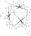
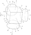
- FIG. 1 is a schematic view of the actuator 1 of the first embodiment.
- FIG. 2 is a view explaining the output members 50 to 70 provided in the actuator 1 illustrated in FIG. 1 . It should be noted that the illustration of the output members 50 to 70 is omitted in FIG. 1 , and the illustration of the base electrodes 20 to 40 is omitted in FIG. 2 .
- the actuator 1 is a soft actuator that performs mechanical work by using, as power, deformation of the flexible electrode 10 that has flexibility.
- the flexible electrode 10 itself deforms. This is different from the conventional soft actuator that uses, as power, deformation of a dielectric elastomer sandwiched between a pair of electrodes.
- the actuator 1 is applicable to various kinds of actuators used for artificial muscle or robots, for example.
- the actuator 1 alone acts as an actuator that can achieve movement with multiple degrees of freedom.
- the actuator 1 can cause the flexible electrode 10 to three-dimensionally deform in the first axis, the second axis, and the third axis that cross each other when a voltage is applied across the base electrodes 20 to 40 and the flexible electrode 10, respectively.
- the actuator 1 can cause the output members 50 to 70 attached to the flexible electrode 10 to be three-dimensionally displaced according to the deformation of the flexible electrode 10, thus outputting work to the outside.
- the actuator 1 includes the flexible electrode 10, the base electrodes 20 to 40, and the output members 50 to 70.
- the flexible electrode 10 is formed of a flexible electric conductor.
- the flexible electrode 10 has flexibility such that it deforms due to the effect of the Coulomb force generated by the voltage applied across the base electrodes 20 to 40 and the flexible electrode 10 and returns to the original shape when the application of the voltage is stopped.
- Examples of the material used for the formation of the flexible electrode 10 may include conductive rubber or conductive gel, for example.
- the conductive rubber may include an elastomer formed by mixture with a conductive material.
- Examples of the conductive material may include fine powder of carbon black, acetylene black, or carbon nanotube, metal fine powder of silver or copper, conductive fine powder having a core-shell structure in which an insulator of silica or alumina, for example, is coated with metal through sputtering, for example.
- Examples of the conductive gel may include a functional gel material obtained by retaining a solvent such as water or a humectant, an electrolyte, an additive, and the like in a three-dimensional polymer matrix.
- the functional gel material may include Technogel (registered trademark) available from Sekisui Kasei Co., Ltd.
- the flexible electrode 10 may be formed by using a viscoelastic body or an elasto-plastic body. In this case, the flexible electrode 10 may be used within a range assumed to be an elastic region, for example.
- the flexible electrode 10 is formed into a three-dimensional shape.
- the flexible electrode 10 is formed into a polyhedron, for example, a hexahedron.
- the flexible electrode 10 of the present embodiment includes a first face 11 crossing the Y-axis and a second face 12 facing the first face 11 on the Y-axis.
- the flexible electrode 10 of the present embodiment includes a third face 13 crossing the X-axis and a fourth face 14 facing the third face 13 on the X-axis.
- the flexible electrode 10 of the present embodiment includes a fifth face 15 crossing the Z-axis and a sixth face 16 facing the fifth face 15 on the Z-axis.
- the flexible electrode 10 of the present embodiment may be formed into a three-dimensional shape such that the first face 11 and the second face 12 intersect the Y-axis, the third face 13 and the fourth face 14 intersect the X-axis, and the fifth face 15 and the sixth face 16 intersect the Z-axis.
- the base electrodes 20 to 40 are formed of a rigid conductive material. Examples of the material used for the formation of the base electrodes 20 to 40 may include a metal material such as iron, copper, or aluminum.
- the base electrodes 20 to 40 each are formed into a plate shape.
- the base electrodes 20 to 40 each may be formed by coating with a conductive metal film, for example, one surface of a substrate formed by using a non-metal material having heat resistance, rigidity, and insulation, such as ceramics.
- the surface of the substrate coated with a metal film is a face facing the flexible electrode 10.
- the base electrodes 20 to 40 include the first base electrode 20, the second base electrode 30, and the third base electrode 40.
- the first base electrode 20 is an electrode for applying a voltage to generate a Coulomb force for causing the flexible electrode 10 to deform mainly along the Y-axis.
- the first base electrode 20 is disposed to face the flexible electrode 10 on the Y-axis.
- the first base electrode 20 has an opposite face 21 facing the flexible electrode 10.
- the opposite face 21 facing the flexible electrode 10 faces the first face 11 of the flexible electrode 10.
- the opposite face 21 facing the flexible electrode 10 is provided with first insulating layers 23a, 23b.
- the first base electrode 20 may be formed of a plurality of electrode portions 25a, 25b.
- the plurality of electrode portions 25a, 25b is insulated from each other by a plate-like insulating portion 26. With the plate-like insulating portion 26, each of the plurality of electrode portions 25a, 25b may independently receive a voltage applied across the first base electrode 20 and the flexible electrode 10.
- each of the plurality of electrode portions 25a, 25b is formed into a plate shape to extend along the Z-axis.
- the plurality of electrode portions 25a, 25b is arranged side by side along the X-axis.
- the plurality of electrode portions 25a, 25b is formed on the YZ plane in a manner symmetric with each other.
- the plurality of electrode portions 25a, 25b respectively has inclined faces 22a, 22b that face the flexible electrode 10 and are inclined with respect to the flexible electrode 10. That is, the opposite face 21 of the first base electrode 20 facing the flexible electrode 10 is formed of the inclined faces 22a, 22b.
- the inclined faces 22a, 22b are inclined with respect to the first face 11.
- the inclined face 22a and the inclined face 22b are inclined in the directions different from each other.
- the expression "the inclined face 22a and the inclined face 22b are inclined in the directions different from each other” means that the normal of the inclined face 22a is not parallel with the normal of the inclined face 22b.
- the normal of the inclined face 22a is inclined in the -X-axis direction with respect to the Y-axis along the normal of the first face 11.
- the normal of the inclined face 22b is inclined in the +X-axis direction with respect to the Y-axis along the normal of the first face 11.
- the first insulating layers 23a, 23b are layers that insulate the first base electrode 20 from the flexible electrode 10.
- the first insulating layer 23a coats the inclined face 22a of the electrode portion 25a that is one of the electrode portions forming the first base electrode 20.
- the first insulating layer 23b coats the inclined face 22b of the electrode portion 25b that is the other one of the electrode portions forming the first base electrode 20.
- the first insulating layers 23a, 23b are formed by using a ferroelectric material including ceramics to surely maintain the electric charge stored in the first base electrode 20 by the voltage applied across the first base electrode 20 and the flexible electrode 10.
- the first insulating layers 23a, 23b are formed by using a ferroelectric material having a perovskite structure.
- ferroelectric material having a perovskite structure may include barium titanate (BaTiO 3 ), lead titanate (PbTiO 3 ), lead zirconate titanate (Pb(Zr, Ti)O 3 ), lanthanum lead zirconate titanate ((Pb, La)(Zr, Ti)O 3 ), strontium titanate (SrTiO 3 ), barium strontium titanate ((Ba, Sr)TiO 3 ), or potassium sodium niobate ((NaK)NbO 3 ).
- the barium titanate may contain dissolved therein a substance, such as CaZrO 3 or BaSnO 3 .
- the material used for the formation of the first insulating layers 23a, 23b may have a high relative dielectric constant so as to generate a Coulomb force to cause the flexible electrode 10 to deform.
- the first insulating layers 23a, 23b may have a relative dielectric constant higher than or equal to 1000 by employing ceramics (fine ceramics), for example.
- the barium titanate has a relative dielectric constant in the range from about 1000 to 10000.
- the lead zirconate titanate has a relative dielectric constant in the range from 500 to 5000.
- the strontium titanate has a relative dielectric constant in the range from 200 to 500.
- the first base electrode 20 is adapted to have a first space 24 formed between the first insulating layers 23a, 23b provided on the opposite face 21 of the first base electrode 20 facing the flexible electrode 10 and the flexible electrode 10.
- the first space 24 is formed between the first insulating layers 23a, 23b provided on the opposite face 21 of the first base electrode 20 facing the flexible electrode 10 and the first face 11 of the flexible electrode 10.
- the Coulomb force causes the flexible electrode 10 to deform toward the first insulating layers 23a, 23b so as to adhere to the first insulating layers 23a, 23b.
- the first space 24 is a space for the flexible electrode 10 to deform toward the first insulating layers 23a, 23b by the voltage applied across the first base electrode 20 and the flexible electrode 10.
- the second base electrode 30 is an electrode for applying a voltage to generate a Coulomb force for causing the flexible electrode 10 to deform mainly along the X-axis.
- the second base electrode 30 is configured in the same manner as the first base electrode 20. That is, the second base electrode 30 is disposed to face the flexible electrode 10 on the X-axis.
- the second base electrode 30 has an opposite face 31 facing the flexible electrode 10. In the present embodiment, the opposite face 31 facing the flexible electrode 10 faces the third face 13 of the flexible electrode 10.
- the opposite face 31 facing the flexible electrode 10 is provided with second insulating layers 33a, 33b.
- the second base electrode 30 may be formed of a plurality of electrode portions 35a, 35b.
- the plurality of electrode portions 35a, 35b is insulated from each other by a plate-like insulating portion 36 and each of the plurality of electrode portions 35a, 35b may independently receive a voltage applied across the second base electrode 30 and the flexible electrode 10.
- the plurality of electrode portions 35a, 35b respectively has inclined faces 32a, 32b that face the flexible electrode 10 and are inclined with respect to the flexible electrode 10.
- the inclined faces 32a, 32b are inclined with respect to the third face 13.
- the inclined face 32a and the inclined face 32b are inclined in the directions different from each other.
- the second insulating layers 33a, 33b are layers that insulate the second base electrode 30 from the flexible electrode 10.
- the second insulating layer 33a coats the inclined face 32a of the electrode portion 35a that is one of the electrode portions forming the second base electrode 30.
- the second insulating layer 33b coats the inclined face 32b of the electrode portion 35b that is the other one of the electrode portions forming the second base electrode 30.
- the second insulating layers 33a, 33b are formed by using a ferroelectric material including ceramics, such as barium titanate, to surely maintain the electric charge stored in the second base electrode 30, and having a high relative dielectric constant.
- a second space 34 is formed between the second insulating layers 33a, 33b and the flexible electrode 10, in which the flexible electrode 10 deforms toward the second insulating layers 33a, 33b by the voltage applied across the second base electrode 30 and the flexible electrode 10.
- the second space 34 is formed between the second insulating layers 33a, 33b provided on the opposite face 31 of the second base electrode 30 facing the flexible electrode 10 and the third face 13 of the flexible electrode 10.
- the third base electrode 40 is an electrode for applying a voltage to generate a Coulomb force for causing the flexible electrode 10 to deform mainly along the Z-axis.
- the third base electrode 40 is configured in the same manner as the first base electrode 20. That is, the third base electrode 40 is disposed to face the flexible electrode 10 on the Z-axis.
- the third base electrode 40 has an opposite face 41 facing the flexible electrode 10. In the present embodiment, the opposite face 41 facing the flexible electrode 10 faces the fifth face 15 of the flexible electrode 10.
- the opposite face 41 facing the flexible electrode 10 is provided with third insulating layers 43a, 43b.
- the third base electrode 40 may be formed of a plurality of electrode portions 45a, 45b.
- the plurality of plurality of electrode portions 45a, 45b is insulated from each other by a plate-like insulating portion 46 and each of the plurality of electrode portions 35a, 35b may independently receive a voltage applied across the third base electrode 40 and the flexible electrode 10.
- the plurality of electrode portions 45a, 45b respectively has inclined faces 42a, 42b that face the flexible electrode 10 and are inclined with respect to the flexible electrode 10.
- the inclined faces 42a, 42b are inclined with respect to the fifth face 15.
- the inclined face 42a and the inclined face 42b are inclined in the directions different from each other.
- the third insulating layers 43a, 43b are layers that insulate the third base electrode 40 from the flexible electrode 10.
- the third insulating layer 43a coats the inclined face 42a of the electrode portion 45a that is one of the electrode portions forming the third base electrode 40.
- the third insulating layer 43b coats the inclined face 42b of the electrode portion 45b that is the other one of the electrode portions forming the third base electrode 40.
- the third insulating layers 43a, 43b are formed by using a ferroelectric material including ceramics.
- a third space 44 is formed between the third insulating layers 43a, 43b and the flexible electrode 10, in which the flexible electrode 10 deforms toward the third insulating layers 43a, 43b by the voltage applied across the third base electrode 40 and the flexible electrode 10.
- the third space 44 is formed between the third insulating layers 43a, 43b provided on the opposite face 41 of the third base electrode 40 facing the flexible electrode 10 and the fifth face 15 of the flexible electrode 10.
- the output members 50 to 70 are adapted to output work to the outside of the actuator 1.
- the output members 50 to 70 are driven members attached to the flexible electrode 10 and adapted to be displaced according to the deformation of the flexible electrode 10. It should be noted that the configuration of the output members 50 to 70 is not limited to the one illustrated in FIG. 2 below, but may be appropriately designed according to, for example, the environment of use of the actuator 1 including the specification of an external device that receives the work of the actuator 1.
- the output members 50 to 70 include the first output member 50, the second output member 60, and the third output member 70.
- the first output member 50 is a driven member adapted to be displaced according to the deformation of the flexible electrode 10 mainly along the Y-axis.
- the first output member 50 is attached to the second face 12 of the flexible electrode 10.
- the first output member 50 may be formed by an output end 51 having a high rigidity coupled to the external device, a beam portion 52 having a high rigidity adapted to support the output end 51, and a coupling portion 53 adapted to couple the beam portion 52 to the flexible electrode 10.
- the beam portion 52 is formed into a cross along a pair of diagonal lines of the square second face 12 and is disposed with a predetermined distance from the second face 12 in the +Y-axis direction.
- the output end 51 is formed in a rod shape so as to protrude in the +Y-axis direction from the intersection point of the cross-shaped beam portion 52.
- the coupling portion 53 includes a horizontal portion 54, which extends from each of the ends of the beam portion 52 in the axial direction of the beam portion 52, and a vertical portion 55, which extends from each of the vertexes of the second face 12 in the vertical direction (+Y-axis direction) of the second face 12 and is orthogonal to the horizontal portion 54.
- the horizontal portion 54 may be formed by a member such as a damper that can be extended and retracted only in the axial direction of the horizontal portion 54.
- the vertical portion 55 may be formed by an elastic member such as a spring that can elastically deform in a direction crossing the axial direction of the vertical portion 55.
- a node 56 between the horizontal portion 54 and the vertical portion 55 may be a hinged node, rotation of which is not restricted, and may be formed by a ball joint, for example.
- a node 57 between the vertical portion 55 and the flexible electrode 10 may be a rigid node, rotation of which is restricted.
- the second output member 60 is a driven member adapted to be displaced according to the deformation of the flexible electrode 10 mainly along the X-axis.
- the second output member 60 is attached to the fourth face 14 of the flexible electrode 10.
- the second output member 60 is formed in the same manner as the first output member 50. That is, the second output member 60 may be formed by an output end 61 coupled to the external device, a beam portion 62 adapted to support the output end 61, and a coupling portion 63 adapted to couple the beam portion 62 to the flexible electrode 10.
- the coupling portion 63 includes a horizontal portion 64, which extends from each of the ends of the cross-shaped beam portion 62 in the axial direction of the beam portion 62, and a vertical portion 65, which extends from each of the vertexes of the fourth face 14 in the vertical direction (+X-axis direction) of the fourth face 14 and is orthogonal to the horizontal portion 64.
- a node 66 between the horizontal portion 64 and the vertical portion 65 may be a hinged node, rotation of which is not restricted, and a node 67 between the vertical portion 65 and the flexible electrode 10 may be a rigid node, rotation of which is restricted.
- the third output member 70 is a driven member adapted to be displaced according to the deformation of the flexible electrode 10 mainly along the Z-axis.
- the third output member 70 is attached to the sixth face 16 of the flexible electrode 10.
- the third output member 70 is formed in the same manner as the first output member 50. That is, the third output member 70 may be formed by an output end 71 coupled to the external device, a beam portion 72 adapted to support the output end 71, and a coupling portion 73 adapted to couple the beam portion 72 to the flexible electrode 10.
- the coupling portion 73 includes a horizontal portion 74, which extends from each of the ends of the cross-shaped beam portion 72 in the axial direction of the beam portion 72, and a vertical portion 75, which extends from each of the vertexes of the sixth face 16 in the vertical direction (+Z-axis direction) of the sixth face 16 and is orthogonal to the horizontal portion 74.
- a node 76 between the horizontal portion 74 and the vertical portion 75 may be a hinged node, rotation of which is not restricted, and a node 77 between the vertical portion 75 and the flexible electrode 10 may be a rigid node, rotation of which is restricted.
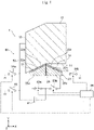
- FIG. 3 is a view explaining a drive circuit 80 of the actuator 1 illustrated in FIG. 1 . It should be noted that the illustration of the second base electrode 30, the third base electrode 40, and the output members 50 to 70 is omitted in FIG. 3. FIG. 3 schematically illustrates the cross section in XY plane of the flexible electrode 10 and the first base electrode 20 illustrated in FIG. 1 .
- the drive circuit 80 is an electric circuit for driving the actuator 1.
- the drive circuit 80 is adapted to drive the actuator 1 by applying a voltage across the base electrodes 20 to 40 and the flexible electrode 10.
- FIG. 3 illustrates only the drive circuit 80 adapted to apply a voltage across the first base electrode 20 and the flexible electrode 10.
- the drive circuit 80 adapted to apply a voltage across the second base electrode 30 or the third base electrode 40 and the flexible electrode 10 is configured in the same manner as the drive circuit 80 adapted to apply a voltage across the first base electrode 20 and the flexible electrode 10. Thus, the descriptions thereof will be omitted.
- the drive circuit 80 includes a power supply 81 formed by a direct voltage source, for example, a wire 82 adapted to couple the elements of the drive circuit 80 and the actuator 1, switches 83a, 83b, 84a, 84b, 85 formed by semiconductor elements, for example, and a control unit 86 formed by an integrated circuit, for example.
- a direct voltage source for example, a wire 82 adapted to couple the elements of the drive circuit 80 and the actuator 1, switches 83a, 83b, 84a, 84b, 85 formed by semiconductor elements, for example, and a control unit 86 formed by an integrated circuit, for example.
- One of the positive terminal and the negative terminal of the power supply 81 is coupled to the flexible electrode 10 by the wire 82, and the other one of the positive terminal and the negative terminal of the power supply 81 is coupled to the first base electrode 20 by the wire 82.
- the other one of the positive terminal and the negative terminal of the power supply 81 is coupled to the electrode portion 25a and the electrode portion 25b forming the first base electrode 20 that are in parallel to each other.
- the switch 83a is coupled between the electrode portion 25a and the power supply 81.
- the switch 83b is coupled between the electrode portion 25b and the power supply 81.
- the switch 84a is coupled between the electrode portion 25a and the frame ground (or earth).
- the switch 84b is coupled between the electrode portion 25b and the frame ground (or earth).
- the switch 85 is coupled between the flexible electrode 10 and the frame ground (or earth). That is, the electrode portions 25a, 25b and the flexible electrode 10 are coupled to the frame ground (or earth) via the switches 84a, 84b, 85, respectively. It should be noted that the power supply 81 may be provided for each of the electrode portion 25a and the electrode portion 25b individually.
- the control unit 86 is a circuit for controlling the elements of the drive circuit 80.
- the control unit 86 is adapted to control the switches 83a, 83b, 84a, 84b, 85 so as to apply a voltage or stop application of the voltage across each of the electrode portions 25a, 25b and the flexible electrode 10.
- the control unit 86 is adapted to independently control the ON/OFF state of the switch 83a and the ON/OFF state of the switch 83b.
- the control unit 86 is adapted to independently control the ON/OFF state of the switch 84a, the ON/OFF state of the switch 84b, and the ON/OFF state of the switch 85.
- the switch 83a when the switch 83a is controlled to be in the ON state, the power supply 81 and the electrode portion 25a become conducting, and in addition, when the switches 84a, 85 are controlled to be in the OFF state, a voltage is applied across the electrode portion 25a and the flexible electrode 10.
- the switch 83a is controlled to be in the OFF state, the power supply 81 and the electrode portion 25a become nonconducting, and the application of the voltage across the electrode portion 25a and the flexible electrode 10 is stopped.
- the application of the voltage across the electrode portion 25b and the flexible electrode 10 is controlled when the control unit 86 controls the ON/OFF state of each of the switches 83b, 84b, 85.
- control unit 86 is adapted to control the output voltage of the power supply 81 so as to control the magnitude of a voltage to be applied across each of the electrode portions 25a, 25b and the flexible electrode 10. This allows the control unit 86 to control the magnitude of the Coulomb force acting on the flexible electrode 10 and control the deformation amount of the flexible electrode 10, thus controlling the displacement amount of the first output member 50.
- the control unit 86 may independently control the magnitude of the voltage to be applied across the electrode portion 25a and the flexible electrode 10 and the magnitude of the voltage to be applied across the electrode portion 25b and the flexible electrode 10. This allows the control unit 86 to partially divide and control the deformation amount of the flexible electrode 10, thus controlling the displacement amount of the first output member 50 in a complicated and fine manner.
- FIG. 4 is a view explaining an aspect of deformation of the flexible electrode 10 when a voltage is applied across the electrode portion 25a, which is one of the electrode portions forming the first base electrode 20, and the flexible electrode 10 illustrated in FIG. 3 .
- a Coulomb force is generated between the first insulating layer 23a and the flexible electrode 10.
- the Coulomb force causes the flexible electrode 10 to be attracted by the first insulating layer 23a.
- the portion of the first face 11 facing the first insulating layer 23a deforms toward the first insulating layer 23a so as to adhere to the first insulating layer 23a. Since the first insulating layer 23a is inclined along the inclined face 22a, the first output member 50 coupled to the second face 12 of the flexible electrode 10 is displaced in the -Y-axis direction and the -X-axis direction.
- the first base electrode 20 can cause the first output member 50 to rotate counterclockwise in the roll direction as viewed in the +Z-axis direction when a voltage is applied only across the electrode portion 25a and the flexible electrode 10. It should be noted that when no electric charge is stored in the electrode portion 25b as in the startup of the actuator 1, for example, the switch 84b in the example illustrated in FIG. 4 may be controlled to be in the OFF state.
- FIG. 5 is a view explaining an aspect of deformation of the flexible electrode 10 when the application of the voltage is stopped after the state illustrated in FIG. 4 .
- the first output member 50 coupled to the second face 12 of the flexible electrode 10 returns to the position in the initial state.
- FIG. 6 is a view explaining an aspect of deformation of the flexible electrode 10 when a voltage is applied across the electrode portion 25b, which is the other one of the electrode portions forming the first base electrode 20, and the flexible electrode 10 illustrated in FIG. 3 .
- the first output member 50 coupled to the second face 12 of the flexible electrode 10 is displaced in the -Y-axis direction and the +X-axis direction. That is, the first base electrode 20 can cause the first output member 50 to rotate clockwise in the roll direction as viewed in the +Z-axis direction when a voltage is applied only across the electrode portion 25b and the flexible electrode 10. It should be noted that when no electric charge is stored in the electrode portion 25a as in the startup of the actuator 1, for example, the switch 84a in the example illustrated in FIG. 6 may be controlled to be in the OFF state.
- the control unit 86 can control the ON/OFF state of each of the switches 83a, 83b, 84a, 84b, 85 to be in the state of FIG. 4 , the state of FIG. 5 , and then the state of FIG. 6 in this order, or after the state of FIG. 6 , to be in the state of FIG. 5 , and then the state of FIG. 4 in this order.
- the state of the first base electrode 20 is alternately switched between the state where a voltage is applied only across the electrode portion 25a and the flexible electrode 10 and the state where a voltage is applied only across the electrode portion 25b and the flexible electrode 10, with interposed therebetween, the state where the application of the voltage is stopped.
- the flexible electrode 10 is alternately switched between the aspect in which the flexible electrode 10 deforms toward the first insulating layer 23a illustrated in FIG. 4 and the aspect in which the flexible electrode 10 deforms toward the first insulating layer 23b illustrated in FIG. 6 , with interposed therebetween, the state where the flexible electrode 10 has returned to the original shape illustrated in FIG. 5 . That is, the deformation direction of the flexible electrode 10 may be alternately switched by the first base electrode 20 between the direction toward the first insulating layer 23a along the inclined face 22a and the direction toward the first insulating layer 23b along the inclined face 22b. Accordingly, the first base electrode 20 can cause the first output member 50 to swing in the direction rotating about the Z-axis.
- FIG. 7 is a view explaining an aspect of deformation of the flexible electrode 10 when a voltage is applied across both of the electrode portions 25a, 25b forming the first base electrode 20 and the flexible electrode 10 illustrated in FIG. 3 .
- the first output member 50 coupled to the second face 12 of the flexible electrode 10 is displaced in the -Y-axis direction. That is, the first base electrode 20 can cause the first output member 50 to translationally move along the Y-axis when a voltage is applied across the electrode portion 25a and the flexible electrode 10 as well as across the electrode portion 25b and the flexible electrode 10.
- the drive circuit 80 adapted to apply a voltage across the second base electrode 30 and the flexible electrode 10 can also independently control a voltage to be applied across each of the electrode portions 35a, 35b forming the second base electrode 30 and the flexible electrode 10 in the same manner as those illustrated in FIG. 4 to FIG. 7 .
- the second base electrode 30 can cause the second output member 60 to rotate counterclockwise or clockwise in the yaw direction as viewed in the +Y-axis direction, and to swing in the direction rotating about the Y-axis. Further, the second base electrode 30 can cause the second output member 60 to translationally move along the X-axis.
- the drive circuit 80 adapted to apply a voltage across the third base electrode 40 and the flexible electrode 10 can also independently control a voltage to be applied across each of the electrode portions 45a, 45b forming the third base electrode 40 and the flexible electrode 10 in the same manner as those illustrated in FIG. 4 to FIG. 7 .
- the third base electrode 40 can cause the third output member 70 to rotate counterclockwise or clockwise in the pitch direction as viewed in the +X-axis direction, and to swing in the direction rotating about the X-axis. Further, the third base electrode 40 can cause the third output member 70 to translationally move along the Z-axis.
- FIG. 8 is a view explaining a principle of detection of a displacement amount of the output members 50 to 70. It should be noted that FIG. 8 corresponds to FIG. 6 .
- the flexible electrode 10 since the output members 50 to 70 are driven in a state of being coupled to the external device, while driven, the flexible electrode 10 receives an external force F due to the coupling to the external device, and thus is prevented from deforming to adhere to the base electrodes 20 to 40. Meanwhile, it is known that there is a predetermined negative correlation between the distance between the base electrodes 20 to 40 and the flexible electrode 10 and the amount of electric charge stored between the base electrodes 20 to 40 and the flexible electrode 10.
- the control unit 86 of the drive circuit 80 can store in advance, as a reference amount of electric charge, the amount of electric charge stored in a state where the output members 50 to 70 are not coupled to the external device and the flexible electrode 10 is adhering to the base electrodes 20 to 40.
- the control unit 86 can calculate a distance between the flexible electrode 10 that has received the external force F and the base electrodes 20 to 40 by comparing the amount of electric charge stored while the actuator 1 is driven and the reference amount of electric charge. From the result of the calculated distance, the control unit 86 can calculate the deformation amount of the flexible electrode 10. From the deformation amount of the flexible electrode 10, the control unit 86 can not only calculate the displacement amount of the output members 50 to 70, but also calculate the magnitude of the external force F acting on the flexible electrode 10.
- the control unit 86 of the drive circuit 80 can detect a displacement amount of each of the output members 50 to 70 by detecting an amount of electric charge stored in the flexible electrode 10.
- the actuator 1 can detect a displacement amount of each the output members 50 to 70 without newly introducing a detection device separate from the actuator 1 such as a laser displacement gage.
- the control unit 86 can perform feedback control of the displacement amount of the output members 50 to 70. Therefore, the actuator 1 can control the movement with multiple degrees of freedom with a simple configuration.
- the actuator 1 includes the base electrodes 20 to 40 disposed to face the flexible electrode 10 on the three axes: X-axis, Y-axis, and Z-axis.
- the actuator 1 of the first embodiment is not limited to this, and may include base electrodes disposed to face the flexible electrode 10 at least on two axes that cross each other.
- the actuator 1 of the first embodiment may include only the first base electrode 20 on the Y-axis and the second base electrode 30 on the X-axis.
- the shape of the flexible electrode 10 may be other than a hexahedron.
- the flexible electrode 10 may include a portion which will not deform according to the above-mentioned Coulomb force, and such a portion may be restricted by being fixed to an external member.
- FIG. 9 is a table showing the results of simulation analysis performed for the operation of the actuator 1 illustrated in FIG. 1 .
- FIG. 10 is a view showing the analysis result of an aspect of deformation of the flexible electrode 10 in a first state illustrated in FIG. 9 .
- FIG. 11 is a view showing the analysis result of an aspect of deformation of the flexible electrode 10 in a second state illustrated in FIG. 9 .
- FIG. 12 is a view showing the analysis result of an aspect of deformation of the flexible electrode 10 in a third state illustrated in FIG. 9 .
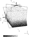
- FIG. 13 is a view showing the analysis result of an aspect of deformation of the flexible electrode 10 in an eighth state illustrated in FIG. 9 . It should be noted that in FIG. 10 to FIG.
- a portion having a high level of gray scale in the flexible electrode 10 indicates that the portion has a large deformation amount (i.e., displacement amount) with reference to the initial state
- a portion having a low level of gray scale in the flexible electrode 10 indicates that the portion has a small deformation amount (i.e., displacement amount) with reference to the initial state.
- the analysis used a model in which the third base electrode 40 and the third output member 70 are omitted from the actuator 1 illustrated in FIG. 1 and FIG. 2 .
- the output end 51 and the beam portion 52 of the first output member 50 each had a Young's modulus of 200 GPa.
- the horizontal portion 54 of the coupling portion 53 of the first output member 50 displacement of the horizontal portion 54 in the axial direction was allowed, whereas displacement and rotation of the horizontal portion 54 in a direction other than the axial direction were restricted.
- the vertical portion 55 of the coupling portion 53 of the first output member 50 relative displacement between the node 56 and the node 57 located on the opposite ends of the vertical portion 55 was restricted, rotation of the node 56 was allowed, and rotation of the node 57 was restricted.
- the magnitude of a voltage to be applied across one of the plurality of electrode portions 25a, 25b forming the first base electrode 20 and the flexible electrode 10 was equal to the magnitude of a voltage to be applied across the other one of the plurality of electrode portions 25a, 25b forming the first base electrode 20 and the flexible electrode 10.
- the same analysis conditions were employed for the second output member 60.
- the sign “ ⁇ ” shows that a voltage is applied, and the sign “ ⁇ ” shows that a voltage is not applied.
- the items “X”, “Y” and “Z” of “First output member 50” show how much the output end 51 of the first output member 50 is displaced along the X-axis, the Y-axis, and the Z-axis from the initial state, respectively.
- the items “X”, “Y” and “Z” of "Second output member 60" show how much the output end 61 of the second output member 60 is displaced along the X-axis, the Y-axis, and the Z-axis from the initial state, respectively.
- a positive displacement amount shows that the output member is displaced in the plus direction of each axis
- a negative displacement amount shows that the output member is displaced in the minus direction of each axis.
- the first state shows that a voltage is applied only across the electrode portion 25a and the flexible electrode 10.
- the output end 51 of the first output member 50 is displaced by 1.39 in the -X-axis direction and by 3.60 in the -Y-axis direction from the initial state, and is not displaced in the ⁇ Z-axis directions.
- the output end 61 of the second output member 60 is displaced in none of the ⁇ X-axis directions, ⁇ Y-axis directions, and ⁇ Z-axis directions from the initial state.
- FIG. 10 illustrates an aspect of deformation of the flexible electrode 10 in the first state.
- the actuator 1 can cause the first output member 50 to rotate counterclockwise in the roll direction as viewed in the +Z-axis direction when a voltage is applied only across the electrode portion 25a and the flexible electrode 10, as explained with reference to FIG. 4 .
- the second state shows that a voltage is applied only across the electrode portion 25b and the flexible electrode 10.
- the output end 51 of the first output member 50 is displaced by 1.39 in the +X-axis direction and by 3.60 in the -Y-axis direction from the initial state, and is not displaced in the ⁇ Z-axis directions.
- the output end 61 of the second output member 60 is displaced by 7.00 in the -Y-axis direction from the initial state and is not displaced in the ⁇ X-axis directions or ⁇ Z-axis directions.
- FIG. 11 illustrates an aspect of deformation of the flexible electrode 10 in the second state.
- the actuator 1 can cause the first output member 50 to rotate clockwise in the roll direction as viewed in the +Z-axis direction when a voltage is applied only across the electrode portion 25b and the flexible electrode 10, as explained with reference to FIG. 6 .
- the third state shows that a voltage is applied across each of the electrode portions 25a, 25b and the flexible electrode 10 and a voltage is not applied across each of the electrode portions 35a, 35b and the flexible electrode 10.
- the output end 51 of the first output member 50 is displaced by 3.60 in the -Y-axis direction from the initial state, and is not displaced in the ⁇ X-axis directions or ⁇ Z-axis directions.
- the output end 61 of the second output member 60 is displaced by 3.60 in the -Y-axis direction from the initial state, and is not displaced in the ⁇ X-axis directions or ⁇ Z-axis directions.
- FIG. 12 illustrates an aspect of deformation of the flexible electrode 10 in the third state.
- the actuator 1 can cause the first output member 50 to translationally move along the Y-axis when a voltage is applied across each of the electrode portions 25a, 25b and the flexible electrode 10, as explained with reference to FIG. 7 .
- the eighth state shows that a voltage is applied across each of the electrode portions 25a, 25b and the flexible electrode 10 and across each of the electrode portions 35a, 35b and the flexible electrode 10.
- the output end 51 of the first output member 50 is displaced by 7.80 in the -X-axis direction and by 7.00 in the -Y-axis direction from the initial state, and is not displaced in the ⁇ Z-axis directions.
- the output end 61 of the second output member 60 is displaced by 7.00 in the -X-axis direction and by 5.00 in the -Y-axis direction from the initial state, and is not displaced in the ⁇ Z-axis directions.
- FIG. 13 illustrates an aspect of deformation of the flexible electrode 10 in the eighth state.
- the actuator 1 can cause the first output member 50 and the second output member 60 to be displaced along the X-axis and the Y-axis, respectively, when a voltage is applied across each of the electrode portions 25a, 25b and the flexible electrode 10 and across each of the electrode portions 35a, 35b and the flexible electrode 10, and can achieve complicated movement with multiple degrees of freedom.
- the actuator 1 of the first embodiment includes the flexible electrode 10, which has flexibility, and the first base electrode 20, which is disposed to face the flexible electrode 10 on the Y-axis and is provided with the first insulating layers 23a, 23b on the opposite face 21 facing the flexible electrode 10.
- the actuator 1 includes the second base electrode 30, which is disposed to face the flexible electrode 10 on the X-axis crossing the Y-axis and is provided with the second insulating layers 33a, 33b on the opposite face 31 facing the flexible electrode 10.
- the actuator 1 includes the first output member 50 and the second output member 60, which are displaced according to the deformation of the flexible electrode 10 and are adapted to output work to the outside.
- the first space 24 is formed between the first insulating layers 23a, 23b and the flexible electrode 10, in which the flexible electrode 10 deforms toward the first insulating layers 23a, 23b by the voltage applied across the first base electrode 20 and the flexible electrode 10.
- the second space 34 is formed between the second insulating layers 33a, 33b and the flexible electrode 10, in which the flexible electrode 10 deforms toward the second insulating layers 33a, 33b by the voltage applied across the second base electrode 30 and the flexible electrode 10.
- the actuator 1 of the first embodiment can cause dielectric polarization of the first insulating layers 23a, 23b provided in the first base electrode 20 by the voltage applied across the first base electrode 20 and the flexible electrode 10 and generate a Coulomb force between the first insulating layers 23a, 23b and the flexible electrode 10.
- the actuator 1 can cause the flexible electrode 10 to deform along the Y-axis by using the effect of the Coulomb force generated between the first insulating layers 23a, 23b and the flexible electrode 10.
- the actuator 1 can cause dielectric polarization of the second insulating layers 33a, 33b provided in the second base electrode 30 by the voltage applied across the second base electrode 30 and the flexible electrode 10 and generate a Coulomb force between the second insulating layers 33a, 33b and the flexible electrode 10.
- the actuator 1 can cause the flexible electrode 10 to deform along the X-axis by using the effect of the Coulomb force generated between the second insulating layers 33a, 33b and the flexible electrode 10.
- the actuator 1 can cause the first output member 50 and the second output member 60 to be displaced along the X-axis and the Y-axis, respectively, according to the deformation of the flexible electrode 10 along the X-axis and the Y-axis, respectively. Therefore, with only one actuator 1 provided with one flexible electrode 10, the actuator 1 of the first embodiment can easily achieve movement with multiple degrees of freedom, even without combining two or more actuators.
- the actuator 1 of the first embodiment can detect a deformation amount of the flexible electrode 10 and a displacement amount of each of the first output member 50 and the second output member 60 by detecting an amount of electric charge stored in the flexible electrode 10 through an existing method. That is, the actuator 1 can detect a displacement amount of each of the first output member 50 and the second output member 60 without newly introducing a detection device separate from the actuator 1. Therefore, the actuator 1 of the first embodiment can control the movement with multiple degrees of freedom with a simple configuration.
- the first base electrode 20 is formed of the plurality of electrode portions 25a, 25b adapted to independently receive a voltage
- the second base electrode 30 is formed of the plurality of electrode portions 35a, 35b adapted to independently receive a voltage.
- the first base electrode 20 can control the voltage applied across the first base electrode 20 and the flexible electrode 10 for each of the plurality of electrode portions 25a, 25b.
- the first base electrode 20 can control the Coulomb force acting on the flexible electrode 10 for each of the plurality of electrode portions 25a, 25b. Accordingly, the first base electrode 20 can cause the flexible electrode 10 to deform in a more complicated and fine manner as compared to the first base electrode 20 not including the plurality of electrode portions 25a, 25b, thus allowing the first output member 50 to be displaced in a complicated and fine manner.
- the second base electrode 30 is formed of the plurality of electrode portions 35a, 35b as described above, the second base electrode 30 can cause the second output member 60 to be displaced in a complicated and fine manner. Therefore, the actuator 1 of the first embodiment can easily achieve complicated and fine movement with multiple degrees of freedom.
- the plurality of electrode portions 25a, 25b respectively has the inclined faces 22a, 22b that face the flexible electrode 10 and are inclined with respect to the flexible electrode 10.
- the plurality of electrode portions 35a, 35b respectively has the inclined faces 32a, 32b that face the flexible electrode 10 and are inclined with respect to the flexible electrode 10.
- the inclined faces 22a, 22b of the plurality of electrode portions 25a, 25b are inclined in the directions different from each other, and the inclined faces 32a, 32b of the plurality of electrode portions 35a, 35b are inclined in the directions different from each other.
- the first base electrode 20 can cause the flexible electrode 10 to deform toward each of the plurality of inclined faces 22a, 22b that are inclined in the directions different from each other with respect to the flexible electrode 10. Accordingly, the first base electrode 20 can cause the first output member 50 to be displaced so as to rotate in the direction crossing the Y-axis.
- the first base electrode 20 can switch the deformation direction of the flexible electrode 10 between the direction toward the inclined face 22a of the one electrode portion 25a and the direction toward the inclined face 22b of the other electrode portion 25b alternately.
- the first base electrode 20 can cause the first output member 50 to be displaced so as to swing in the direction crossing the Y-axis.
- the second base electrode 30 can cause the second output member 60 to be displaced so as to rotate or swing in the direction crossing the X-axis. Therefore, the actuator 1 of the first embodiment can easily achieve various types of movement, in addition to the transitional movement along the X-axis or the Y-axis.
- the flexible electrode 10 is formed into a hexahedron, which has the first face 11 crossing the Y-axis, the second face 12 facing the first face 11 on the Y-axis, the third face 13 crossing the X-axis, and the fourth face 14 facing the third face 13 on the X-axis.
- the opposite face 21 facing the flexible electrode 10 faces the first face 11 of the flexible electrode 10
- the first space 24 is formed between the first insulating layers 23a, 23b provided on the opposite face 21 of the first base electrode 20 facing the flexible electrode 10 and the first face 11.
- the opposite face 31 facing the flexible electrode 10 faces the third face 13 of the flexible electrode 10, and the second space 34 is formed between the second insulating layers 33a, 33b provided on the opposite face 31 of the second base electrode 30 facing the flexible electrode 10 and the third face 13.
- the actuator 1 of the first embodiment includes the first output member 50 attached to the second face 12 and the second output member 60 attached to the fourth face 14.
- the actuator 1 of the first embodiment can cause the first output member 50 and the second output member 60 to be displaced along the Y-axis and the X-axis, respectively, even with a simple structure including the flexible electrode 10, the first base electrode 20, and the second base electrode 30. Therefore, the actuator 1 of the first embodiment can more easily achieve movement with multiple degrees of freedom.
- the actuator 1 of the first embodiment further includes the third base electrode 40 disposed to face the flexible electrode 10 on the Z-axis and is provided with the third insulating layers 43a, 43b on the opposite face 41 facing the flexible electrode 10.
- the third space 44 is formed between the third insulating layers 43a, 43b and the flexible electrode 10, in which the flexible electrode 10 deforms toward the third insulating layers 43a, 43b by the voltage applied across the third base electrode 40 and the flexible electrode 10.
- the actuator 1 of the first embodiment can cause the flexible electrode 10 to deform along the Z-axis in addition to the X-axis and the Y-axis.
- the actuator 1 can cause the third output member 70 to be displaced along the Z-axis. Therefore, the actuator 1 of the first embodiment can easily achieve movement with greater degrees of freedom.
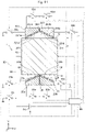
- FIG. 14 is a schematic view of an actuator 1 of the second embodiment. It should be noted that FIG. 14 corresponds to FIG. 3 .
- the actuator 1 of the second embodiment further includes a movable base electrode 201, which is different from the actuator 1 of the first embodiment.
- the movable base electrode 201 is an electrode that is disposed opposite to the first base electrode 20 with at least a portion of the flexible electrode 10 interposed therebetween on the Y-axis, and is adapted to be movable along the Y-axis with respect to the first base electrode 20.
- the movable base electrode 201 includes an opposite face 211 facing the flexible electrode 10 in the same manner as the first base electrode 20.
- the opposite face 211 facing the flexible electrode 10 faces the second face 12 of the flexible electrode 10.
- the opposite face 211 facing the flexible electrode 10 is formed into a shape to fit into the opposite face 21 of the first base electrode 20 facing the flexible electrode 10.
- the opposite face 211 facing the flexible electrode 10 is provided with insulating layers 231a, 231b.
- the insulating layers 231a, 231b are formed by using a ferroelectric material including ceramics.
- a space 241 is formed between the insulating layers 231a, 231b and the flexible electrode 10, in which the movable base electrode 201 moves by the voltage applied across the movable base electrode 201 and the flexible electrode 10.
- the space 241 is formed between the insulating layers 231a, 231b provided on the opposite face 211 of the movable base electrode 201 facing the flexible electrode 10 and the second face 12 of the flexible electrode 10.
- the movable base electrode 201 may be formed of a plurality of electrode portions 251a, 251b.
- the plurality of electrode portions 251a, 251b is insulated from each other by a plate-like insulating portion 261 and each of the plurality of electrode portions 251a, 251b may independently receive a voltage applied across the movable base electrode 201 and the flexible electrode 10.
- the plurality of electrode portions 251a, 251b respectively has inclined faces 221a, 221b that face the flexible electrode 10 and are inclined with respect to the flexible electrode 10.
- the inclined faces 221a, 221b are inclined with respect to the second face 12.
- the inclined face 221a and the inclined face 221b are inclined in the directions different from each other.
- the inclined face 221a is formed into a shape to fit into the inclined face 22a of the first base electrode 20.
- the inclined face 221b is formed into a shape to fit into the inclined face 22b of the first base electrode 20.
- the opposite face 211 formed of the inclined faces 221a, 221b facing the flexible electrode 10 is recessed in the +Y-axis direction and is formed into a valley shape having a ridge along the Z-axis.
- the first output member 50 of the second embodiment may be attached to a face 271 of the movable base electrode 201.
- the face 271 of the movable base electrode 201 is a face positioned opposite to the opposite face 211 of the movable base electrode 201 in the direction along the Y-axis.
- the first output member 50 of the second embodiment may be attached to the second face 12 of the flexible electrode 10, not to the movable base electrode 201.
- the flexible electrode 10 is coupled to one of the positive terminal and the negative terminal of the power supply 81.
- the first base electrode 20 and the movable base electrode 201 are coupled in parallel to the other one of the positive terminal and the negative terminal of the power supply 81.
- the electrode portion 25a and the electrode portion 25b forming the first base electrode 20 are coupled to each other in parallel to the other one of the positive terminal and the negative terminal of the power supply 81.
- the electrode portion 251a and the electrode portion 251b forming the movable base electrode 201 are coupled to each other in parallel to the other one of the positive terminal and the negative terminal of the power supply 81.
- the drive circuit 80 of the second embodiment further includes switches 83c, 83d, 84c, 84d, which is different from the drive circuit 80 of the first embodiment.
- the switch 83c is coupled between the electrode portion 251a and the power supply 81.
- the switch 83d is coupled between the electrode portion 251b and the power supply 81.
- the switch 84c is coupled between the electrode portion 251a and the frame ground (or earth).
- the switch 84d is coupled between the electrode portion 251b and the frame ground (or earth).
- the control unit 86 controls the ON/OFF state of the switches 83c, 83d, 84c, 84d independently.
- the first face 11 deforms toward the first insulating layers 23a, 23b so as to adhere to the first insulating layers 23a, 23b.
- the second face 12 of the flexible electrode 10 deforms into a shape along the inclined faces 22a, 22b coated with the first insulating layers 23a, 23b (see FIG. 12 ).
- the actuator 1 of the second embodiment when both of the switch 83c and the switch 83d are controlled to be in the ON state and the switches 84c, 84d are controlled to be in the OFF state, a Coulomb force is generated between the insulating layers 231a, 231b of the movable base electrode 201 and the flexible electrode 10.
- the direction of this Coulomb force is equal to the direction of the Coulomb force generated between the first insulating layers 23a, 23b of the first base electrode 20 and the flexible electrode 10. That is, in the actuator 1 of the second embodiment, the Coulomb force that causes the flexible electrode 10 to deform along the Y-axis can be enhanced as compared to the first embodiment.
- the movable base electrode 201 moves toward the flexible electrode 10 such that the insulating layers 231a, 231b adhere to the second face 12 that has deformed into the shape along the inclined faces 221a, 221b.
- the first output member 50 attached to the face 271 of the movable base electrode 201 is displaced in the -Y-axis direction.
- the actuator 1 of the second embodiment can cause the first output member 50 to transitionally move along the Y-axis.
- the actuator 1 of the second embodiment further includes the movable base electrode 201 that is disposed opposite to the first base electrode 20 with at least a portion of the flexible electrode 10 interposed therebetween on the Y-axis, and is adapted to move along the Y-axis with respect to the first base electrode 20.
- the movable base electrode 201 is formed into a shape to fit into the opposite face 21 of the first base electrode 20, and the opposite face 211 facing the flexible electrode 10 is provided with the insulating layers 231a, 231b.
- the space 241 is formed between the insulating layers 231a, 231b of the movable base electrode 201 and the flexible electrode 10, in which the movable base electrode 201 moves by the voltage applied across the movable base electrode 201 and the flexible electrode 10.
- the actuator 1 of the second embodiment can cause the Coulomb force generated between the insulating layers 231a, 231b of the movable base electrode 201 and the flexible electrode 10 to act on the flexible electrode 10.
- the direction of the Coulomb force generated between the insulating layers 231a, 231b of the movable base electrode 201 and the flexible electrode 10 is equal to the direction of the Coulomb force generated between the first insulating layers 23a, 23b of the first base electrode 20 and the flexible electrode 10. That is, the actuator 1 of the second embodiment can enhance the Coulomb force that causes the flexible electrode 10 to deform along the Y-axis.
- the actuator 1 of the second embodiment can enhance the power to cause the first output member 50 to be displaced along the Y-axis, it can have a higher output in the direction along the Y-axis. Therefore, the actuator 1 of the second embodiment can easily achieve movement with multiple degrees of freedom and can also increase an output.
- the opposite face 211 (i.e., the inclined faces 221a, 221b) of the movable base electrode 201 is formed into a shape to fit into the opposite face 21 (i.e., the inclined faces 22a, 22b) of the first base electrode 20.
- the actuator 1 of the second embodiment can further enhance the Coulomb force generated between the insulating layers 231a, 231b of the movable base electrode 201 and the flexible electrode 10. Since the actuator 1 of the second embodiment can further enhance the power to cause the first output member 50 to be displaced along the Y-axis, it can have an even higher output in the direction along the Y-axis. Therefore, the actuator 1 of the second embodiment can easily achieve movement with multiple degrees of freedom and can further increase an output.
- the actuator 1 of the second embodiment includes the movable base electrode 201 that is disposed opposite to the first base electrode 20 with at least a portion of the flexible electrode 10 interposed therebetween on the Y-axis.
- the actuator 1 of the second embodiment is not limited to this, and may further include a movable base electrode that is disposed opposite to the second base electrode 30 with at least a portion of the flexible electrode 10 interposed therebetween on the X-axis.
- the actuator 1 of the second embodiment may further include a movable base electrode that is disposed opposite to the third base electrode 40 with at least a portion of the flexible electrode 10 interposed therebetween on the Z-axis.
- FIG. 15 is a schematic view of an actuator 1 of the third embodiment. It should be noted that FIG. 15 corresponds to FIG. 3 . The illustration of the control unit 86 is omitted in FIG. 15 .
- the actuator 1 of the third embodiment has an inner space 17 in the flexible electrode 10. That is, the flexible electrode 10 of the third embodiment has a hollow structure. With this configuration, the flexible electrode 10 of the third embodiment can deform more easily as compared to the flexible electrode 10 with a solid structure. Accordingly, the actuator 1 of the third embodiment can cause the flexible electrode 10 to deform even if a voltage applied to the flexible electrode 10 is reduced. This can reduce power consumption and easily ensure insulation, and thus can increase safety. In addition, the actuator 1 of the third embodiment can reduce its weight and cost as compared to the one in which the flexible electrode 10 has a solid structure. Therefore, the actuator 1 of the third embodiment can achieve movement with multiple degrees of freedom even more easily and safely.
- FIG. 16 is a schematic view of an actuator 1 of the fourth embodiment. It should be noted that FIG. 16 corresponds to FIG. 14 . The illustration of the control unit 86 is omitted in FIG. 16 .
- the actuator 1 of the fourth embodiment includes the inner space 17 in the flexible electrode 10 as in the third embodiment.
- the actuator 1 of the fourth embodiment includes the movable base electrode 201 as in the second embodiment.
- the actuator 1 of the fourth embodiment includes the movable base electrode 201 disposed in the inner space 17.
- the actuator 1 of the fourth embodiment can reduce its size as compared to the one in which the movable base electrode 201 is disposed outside of the flexible electrode 10. Therefore, the actuator 1 of the fourth embodiment can easily achieve movement with multiple degrees of freedom and can achieve downsizing.
- the switches 83c, 83d may be disposed in the inner space 17 of the flexible electrode 10 as illustrated in FIG. 16 , or may be disposed outside of the flexible electrode 10.
- FIG. 17 is a schematic view of an actuator 1 of the fifth embodiment.
- FIG. 18 is a schematic view of the first base electrode 20 illustrated in FIG. 17 .
- FIG. 19 is a schematic view of another example of the first base electrode 20 illustrated in FIG. 18 . It should be noted that FIG. 17 corresponds to FIG. 1 .
- the illustration of the first insulating layer 23 is omitted in FIG. 18 and FIG. 19 .
- the base electrodes 20 to 40 each are formed into a dome shape, such as a hemisphere.
- the first base electrode 20 of the fifth embodiment is disposed such that the top portion of the dome faces the first face 11 of the flexible electrode 10 and the central axis of the dome is along the Y-axis.
- the second base electrode 30 of the fifth embodiment is disposed such that the top portion of the dome faces the third face 13 of the flexible electrode 10 and the central axis of the dome is along the X-axis.
- the third base electrode 40 of the fifth embodiment is disposed such that the top portion of the dome faces the fifth face 15 of the flexible electrode 10 and the central axis of the dome is along the Z-axis.
- the first base electrode 20 of the fifth embodiment includes the opposite face 21 facing the flexible electrode 10 as in the first embodiment.
- the opposite face 21 facing the flexible electrode 10 is provided with the first insulating layer 23.
- the first insulating layer 23 is formed by using a ferroelectric material including ceramics as in the first embodiment.
- the first space 24 is formed between the first insulating layer 23 and the flexible electrode 10, in which the flexible electrode 10 deforms toward the first insulating layer 23 by the voltage applied across the first base electrode 20 and the flexible electrode 10.
- the second base electrode 30 of the fifth embodiment includes the opposite face 31 facing the flexible electrode 10.
- the opposite face 31 facing the flexible electrode 10 is provided with the second insulating layer 33.
- the second insulating layer 33 is formed by using a ferroelectric material including ceramics.
- the second space 34 is formed between the second insulating layer 33 and the flexible electrode 10, in which the flexible electrode 10 deforms toward the second insulating layer 33 by the voltage applied across the second base electrode 30 and the flexible electrode 10.
- the third base electrode 40 of the fifth embodiment includes the opposite face 41 facing the flexible electrode 10.
- the opposite face 41 facing the flexible electrode 10 is provided with the third insulating layer 43.
- the third insulating layer 43 is formed by using a ferroelectric material including ceramics.
- the third space 44 is formed between the third insulating layer 43 and the flexible electrode 10, in which the flexible electrode 10 deforms toward the third insulating layer 43 by the voltage applied across the third base electrode 40 and the flexible electrode 10.
- the first base electrode 20 of the fifth embodiment may be formed of a plurality of electrode portions 25c to 25f as in the first embodiment.
- the plurality of electrode portions 25c to 25f is insulated from each other by the plate-like insulating portion 26 and each of the plurality of electrode portions 25c to 25f may independently receive a voltage applied across the first base electrode 20 and the flexible electrode 10.
- the plurality of electrode portions 25c to 25f respectively has inclined faces 22c to 22f that face the flexible electrode 10 and are inclined with respect to the flexible electrode 10.
- the inclined faces 22c to 22f are inclined in the directions different from each other.
- the plurality of electrode portions 25c to 25f is disposed along the direction rotating about the Y-axis (yaw direction).
- the plurality of electrode portions 25c to 25f may be formed by dividing the hemispherical first base electrode 20 at regular intervals in the direction rotating about the Y-axis.
- the second base electrode 30 of the fifth embodiment may be formed of a plurality of electrode portions, which is insulated from each other and is adapted to independently receive a voltage applied across the second base electrode 30 and the flexible electrode 10.
- the plurality of electrode portions forming the second base electrode 30 of the fifth embodiment respectively has inclined faces that face the flexible electrode 10 and are inclined with respect to the flexible electrode 10.
- the plurality of electrode portions forming the second base electrode 30 of the fifth embodiment is disposed along the direction rotating about the X-axis (pitch direction).
- the third base electrode 40 of the fifth embodiment may be formed of a plurality of electrode portions, which is insulated from each other and is adapted to independently receive a voltage applied across the third base electrode 40 and the flexible electrode 10.
- the plurality of electrode portions forming the third base electrode 40 of the fifth embodiment respectively has inclined faces that face the flexible electrode 10 and are inclined with respect to the flexible electrode 10.
- the plurality of electrode portions forming the third base electrode 40 of the fifth embodiment is disposed along the direction rotating about the Z-axis (roll direction).
- the plurality of electrode portions 25c to 25f forming the first base electrode 20 is disposed along the direction rotating about the Y-axis
- the plurality of electrode portions forming the second base electrode 30 is disposed along the direction rotating about the X-axis.
- the first base electrode 20 of the fifth embodiment can sequentially apply a voltage or sequentially stop application of the voltage across the first base electrode 20 and the flexible electrode 10 for each of the plurality of electrode portions 25c to 25f along the direction rotating about the Y-axis.
- the first base electrode 20 of the fifth embodiment can sequentially cause the flexible electrode 10 to deform toward each of the plurality of electrode portions 25c to 25f disposed along the direction rotating about the Y-axis.
- the first base electrode 20 of the fifth embodiment can cause the first output member 50 to be displaced to precess about the Y-axis as a rotation axis.
- the second base electrode 30 when the second base electrode 30 is formed of a plurality of electrode portions as described above, the second base electrode 30 can cause the second output member 60 to be displaced to precess about the X-axis as a rotation axis. Therefore, the actuator 1 of the fifth embodiment can easily achieve various types of movement, in addition to the transitional movement along the X-axis or the Y-axis.
- the first base electrode 20 of the fifth embodiment can cause the first output member 50 to transitionally move along the Y-axis.
- a voltage, which is applied across the first base electrode 20 and the flexible electrode 10 to one of the plurality of electrode portions 25c to 25f, the first base electrode 20 of the fifth embodiment can cause the first output member 50 to rotate in the direction (the direction crossing the Y-axis) toward the inclined face of the one electrode portion.
- the first base electrode 20 of the fifth embodiment can cause the first output member 50 to swing in the direction crossing the Y-axis. That is, the actuator 1 of the fifth embodiment can cause the first output member 50 to not only transitionally move along the Y-axis but also to rotate or swing in the direction crossing the Y-axis. In the same manner as the first output member 50, the actuator 1 of the fifth embodiment can cause the second output member 60 to not only transitionally move along the X-axis but also to rotate or swing in the direction crossing the X-axis. In the same manner as the first output member 50, the actuator 1 of the fifth embodiment can cause the third output member 70 to not only transitionally move along the Z-axis but also to rotate or swing in the direction crossing the Z-axis.
- the number of electrode portions forming the base electrodes 20 to 40 of the fifth embodiment is not particularly limited.
- the first base electrode 20 of the fifth embodiment may be formed of a plurality of electrode portions 25g to 25n as illustrated in FIG. 19 .
- the plurality of electrode portions 25g to 25n is insulated from each other by the plate-like insulating portion 26 and each of the plurality of electrode portions 25g to 25n may independently receive a voltage applied across the first base electrode 20 and the flexible electrode 10.
- the flexible electrode 10 can deform in a more complicated and fine manner, thus allowing the output members 50 to 70 to be displaced in a complicated and fine manner.
Landscapes
- General Electrical Machinery Utilizing Piezoelectricity, Electrostriction Or Magnetostriction (AREA)
Abstract
Description
- The present invention relates to actuators.
- There is known a soft actuator that performs mechanical work by using deformation of a flexible member as power (for example, Patent Literature 1).
-
Patent Literature 1 discloses an actuator in which an electroactive polymer is sandwiched between a pair of electrodes. In the actuator disclosed inPatent Literature 1, the electrodes as a pair are attracted to each other due to the Coulomb force of the charges stored by the voltage applied across the pair of electrodes, and the electroactive polymer deforms, thereby generating a displacement between the electrodes. - Patent Literature 1:
JP 5714200 B - However, the actuator disclosed in
Patent Literature 1 can achieve movement with only one degree of freedom in a direction along the interelectrode distance or a direction along the electrodes. To achieve movement with multiple degrees of freedom by the actuator disclosed inPatent Literature 1, two or more actuators need to be combined, which may cause a device to have a complicated structure. - The present invention has been made in view of the foregoing, and provides a novel actuator that can easily achieve movement with multiple degrees of freedom.
- In view of the foregoing, the actuator according to the present invention includes a flexible electrode having flexibility; a first base electrode disposed to face the flexible electrode on a first axis and provided with a first insulating layer on an opposite face facing the flexible electrode; a second base electrode disposed to face the flexible electrode on a second axis crossing the first axis and provided with a second insulating layer on an opposite face facing the flexible electrode; and an output member adapted to be displaced according to deformation of the flexible electrode and output work to an outside, in which a first space is formed between the first insulating layer and the flexible electrode, in which the flexible electrode deforms toward the first insulating layer by a voltage applied across the first base electrode and the flexible electrode, and a second space is formed between the second insulating layer and the flexible electrode, in which the flexible electrode deforms toward the second insulating layer by a voltage applied across the second base electrode and the flexible electrode.
- With such a configuration, the actuator according to the present invention can cause dielectric polarization of the first insulating layer provided in the first base electrode by the voltage applied across the first base electrode and the flexible electrode and generate a Coulomb force between the first insulating layer and the flexible electrode. The actuator can cause the flexible electrode to deform along the first axis by using the effect of the Coulomb force generated between the first insulating layer and the flexible electrode. In the same manner, the actuator can cause dielectric polarization of the second insulating layer provided in the second base electrode by the voltage applied across the second base electrode and the flexible electrode and generate a Coulomb force between the second insulating layer and the flexible electrode. The actuator can cause the flexible electrode to deform along the second axis by using the effect of the Coulomb force generated between the second insulating layer and the flexible electrode. The actuator can cause the output members to be displaced along the first axis and the second axis according to the deformation of the flexible electrode along the first axis and the second axis, respectively. Therefore, with only one actuator provided with one flexible electrode, the actuator according to the present invention can easily achieve movement with multiple degrees of freedom, even without combining two or more actuators.
- In addition, the actuator according to the present invention can detect a deformation amount of the flexible electrode by detecting an amount of electric charge stored in the flexible electrode and can detect a displacement amount of the output member by using a known method. That is, the actuator can detect the displacement amount of the output member without newly introducing a detection device separate from the actuator. Therefore, the actuator according to the present invention can control the movement with multiple degrees of freedom with a simple configuration.
- In some embodiments, the first base electrode and the second base electrode each include a plurality of electrode portions adapted to independently receive the voltage.
- With such an aspect, since the first base electrode can control the voltage applied across the first base electrode and the flexible electrode for each of the plurality of electrode portions, the first base electrode can control the Coulomb force acting on the flexible electrode for each of the plurality of electrode portions. Accordingly, the first base electrode can cause the flexible electrode to deform in a more complicated and fine manner as compared to the first base electrode not including the plurality of electrode portions, thus allowing the output member to be displaced in a complicated and fine manner. Likewise, also when the second base electrode is formed of the plurality of electrode portions as described above, the second base electrode can cause the output member to be displaced in a complicated and fine manner. Therefore, the actuator can easily achieve complicated and fine movement with multiple degrees of freedom.
- In some embodiments, each of the plurality of electrode portions has an inclined face that faces the flexible electrode and is inclined with respect to the flexible electrode, and the inclined faces of the plurality of electrode portions are inclined in directions different from each other.
- With such an aspect, the first base electrode can cause the flexible electrode to deform toward each of the plurality of inclined faces that are inclined in the directions different from each other with respect to the flexible electrode. Accordingly, the first base electrode can cause the output member to be displaced so as to rotate in the direction crossing the first axis. In particular, by alternately applying a voltage and stopping application of the voltage between one of the plurality of electrode portions and the other one of the plurality of electrode portions, the first base electrode can switch the deformation direction of the flexible electrode between the direction toward the inclined face of the one electrode portion and the direction toward the inclined face of the other electrode portion alternately. Accordingly, the first base electrode can cause the output member to be displaced so as to swing in the direction crossing the first axis. Likewise, also when the plurality of electrode portions forming the second base electrode has the inclined faces as described above, the second base electrode can cause the output member to be displaced so as to rotate or swing in the direction crossing the second axis. Therefore, the actuator can easily achieve various types of movement, in addition to the transitional movement along the first axis or the second axis.
- In some embodiments, the plurality of electrode portions forming the first base electrode is disposed along a direction rotating about the first axis, and the plurality of electrode portions forming the second base electrode is disposed along a direction rotating about the second axis.
- With such an aspect, the first base electrode can sequentially apply a voltage or sequentially stop application of the voltage across the first base electrode and the flexible electrode for each of the plurality of electrode portions along the direction rotating about the first axis. The first base electrode can sequentially cause the flexible electrode to deform toward each of the plurality of electrode portions disposed along the direction rotating about the first axis. Accordingly, the first base electrode can cause the output member to be displaced so as to precess about the first axis as a rotation axis. Likewise, also when the second base electrode is formed of a plurality of electrode portions as described above, the second base electrode can cause the output member to be displaced so as to precess about the second axis as a rotation axis. Therefore, the actuator can easily achieve various types of movement, in addition to the transitional movement along the first axis or the second axis.
- In some embodiments, the flexible electrode has a hollow structure.
- With such an aspect, the flexible electrode can deform more easily as compared to the flexible electrode with a solid structure. Accordingly, the actuator can cause the flexible electrode to deform even if a voltage applied to the flexible electrode is reduced. This can reduce power consumption and easily ensure insulation, and thus can increase safety. In addition, the actuator can reduce its weight and cost as compared to the one in which the flexible electrode has a solid structure. Therefore, the actuator can achieve movement with multiple degrees of freedom more easily and safely.
- In some embodiments, the actuator further includes a movable base electrode disposed opposite to the first base electrode with at least a portion of the flexible electrode interposed therebetween on the first axis and adapted to move along the first axis with respect to the first base electrode, in which the movable base electrode is provided with an insulating layer on an opposite face facing the flexible electrode, and a space is formed between the insulating layer of the movable base electrode and the flexible electrode, in which the movable base electrode moves by a voltage applied across the movable base electrode and the flexible electrode.
- With such an aspect, the actuator can cause the Coulomb force generated between the insulating layer of the first base electrode and the flexible electrode to act on the flexible electrode. In addition, the actuator can cause the Coulomb force generated between the insulating layer of the movable base electrode and the flexible electrode to act on the flexible electrode. The direction of the Coulomb force generated between the insulating layer of the movable base electrode and the flexible electrode is equal to the direction of the Coulomb force generated between the first insulating layer of the first base electrode and the flexible electrode. That is, the actuator can enhance the Coulomb force that causes the flexible electrode to deform along the first axis. Since the actuator can enhance the power to cause the output member to be displaced along the first axis, it can have a higher output in the direction along the first axis. Therefore, the actuator can easily achieve movement with multiple degrees of freedom and can also increase an output.
- In some embodiments, the flexible electrode is formed into a hexahedron, the hexahedron including a first face crossing the first axis, a second face facing the first face on the first axis, a third face crossing the second axis, and a fourth face facing the third face on the second axis, the opposite face of the first base electrode facing the flexible electrode faces the first face, the first space is formed between the first insulating layer provided on the opposite face of the first base electrode facing the flexible electrode and the first face, the opposite face of the second base electrode facing the flexible electrode faces the third face, the second space is formed between the second insulating layer provided on the opposite face of the second base electrode facing the flexible electrode and the third face, and the output member includes a first output member attached to the second face and a second output member attached to the fourth face.
- With such an aspect, the actuator can cause the first output member and the second output member to be displaced along the first axis and the second axis, respectively, even with a simple structure including the flexible electrode, the first base electrode, and the second base electrode. Therefore, the actuator can more easily achieve movement with multiple degrees of freedom.
- In some embodiments, the actuator further includes a third base electrode disposed to face the flexible electrode on a third axis crossing each of the first axis and the second axis and provided with a third insulating layer on an opposite face facing the flexible electrode, in which a third space is formed between the third insulating layer and the flexible electrode, in which the flexible electrode deforms toward the third insulating layer by a voltage applied across the third base electrode and the flexible electrode.
- With such an aspect, the actuator can cause the flexible electrode to deform along the third axis in addition to the first axis and the second axis. The actuator can cause the output member to be displaced along the third axis in addition to the first axis and the second axis. Therefore, the actuator can easily achieve movement with greater degrees of freedom.
- According to the present invention, a novel actuator that can easily achieve movement with multiple degrees of freedom can be provided.
-
-
FIG. 1 is a schematic view of an actuator of a first embodiment; -
FIG. 2 is a view explaining output members provided in the actuator illustrated inFIG. 1 ; -
FIG. 3 is a view explaining a drive circuit of the actuator illustrated inFIG. 1 ; -
FIG. 4 is a view explaining an aspect of deformation of a flexible electrode when a voltage is applied across one of electrode portions forming a first base electrode and the flexible electrode illustrated inFIG. 3 ; -
FIG. 5 is a view explaining an aspect of deformation of the flexible electrode when the application of the voltage is stopped after the state illustrated inFIG. 4 ; -
FIG. 6 is a view explaining an aspect of deformation of the flexible electrode when a voltage is applied across the other one of the electrode portions forming the first base electrode and the flexible electrode illustrated inFIG. 3 ; -
FIG. 7 is a view explaining an aspect of deformation of the flexible electrode when a voltage is applied across both of the electrode portions forming the first base electrode and the flexible electrode illustrated inFIG. 3 ; -
FIG. 8 is a view explaining a principle of detection of a displacement amount of an output member; -
FIG. 9 is a table showing the results of simulation analysis performed for the operation of the actuator illustrated inFIG. 1 ; -
FIG. 10 is a view showing the analysis result of an aspect of deformation of the flexible electrode in a first state illustrated inFIG. 9 ; -
FIG. 11 is a view showing the analysis result of an aspect of deformation of the flexible electrode in a second state illustrated inFIG. 9 ; -
FIG. 12 is a view showing the analysis result of an aspect of deformation of the flexible electrode in a third state illustrated inFIG. 9 ; -
FIG. 13 is a view showing the analysis result of an aspect of deformation of the flexible electrode in an eighth state illustrated inFIG. 9 ; -
FIG. 14 is a schematic view of an actuator of a second embodiment; -
FIG. 15 is a schematic view of an actuator of a third embodiment; -
FIG. 16 is a schematic view of an actuator of a fourth embodiment; -
FIG. 17 is a schematic view of an actuator of a fifth embodiment; -
FIG. 18 is a schematic view of a first base electrode illustrated inFIG. 17 ; and -
FIG. 19 is a schematic view of another example of the first base electrode illustrated inFIG. 18 . - Hereinafter, embodiments of the present invention will be described with reference to the drawings. In each of the embodiments, unless otherwise specified, the configuration denoted by the same reference numeral has the same function in the embodiments, and descriptions thereof will be omitted. In addition, orthogonal coordinate axes including the X-axis, Y-axis, and Z-axis are shown in the drawings as appropriate in order to clarify the explanation of the position of each unit.
- As illustrated in
FIG. 1 , the origin of the orthogonal coordinate axes is the center of aflexible electrode 10 described later. However, the orthogonal coordinate axes may be shown in the margin of the drawings for the sake of simplification of the drawings. The X-axis, Y-axis, and Z-axis respectively correspond to the "second axis," "first axis," and "third axis" recited in the claims as one example. - In the present embodiment, the direction rotating about the X-axis, the direction rotating about the Y-axis, and the direction rotating about the Z-axis may also be referred to as "pitch direction," "yaw direction," and "roll direction," respectively. In the present embodiment, a
first base electrode 20, asecond base electrode 30, and athird base electrode 40, which will be described later, may also be collectively referred to as "base electrodes 20 to 40." In the present embodiment, afirst output member 50, asecond output member 60, and athird output member 70, which will be described later, may also be collectively referred to as "output members 50 to 70." In addition, in the present embodiment, the expression "A faces B" may include not only the case where a face of A facing B is parallel with a face of B facing A, but also the case where a face of A facing B is not parallel with a face of B facing A. - An
actuator 1 of the first embodiment will be described with reference toFIG. 1 to FIG. 13 . -
FIG. 1 is a schematic view of theactuator 1 of the first embodiment.FIG. 2 is a view explaining theoutput members 50 to 70 provided in theactuator 1 illustrated inFIG. 1 . It should be noted that the illustration of theoutput members 50 to 70 is omitted inFIG. 1 , and the illustration of thebase electrodes 20 to 40 is omitted inFIG. 2 . - The
actuator 1 is a soft actuator that performs mechanical work by using, as power, deformation of theflexible electrode 10 that has flexibility. In theactuator 1, theflexible electrode 10 itself deforms. This is different from the conventional soft actuator that uses, as power, deformation of a dielectric elastomer sandwiched between a pair of electrodes. Theactuator 1 is applicable to various kinds of actuators used for artificial muscle or robots, for example. - The
actuator 1 alone acts as an actuator that can achieve movement with multiple degrees of freedom. Theactuator 1 can cause theflexible electrode 10 to three-dimensionally deform in the first axis, the second axis, and the third axis that cross each other when a voltage is applied across thebase electrodes 20 to 40 and theflexible electrode 10, respectively. Theactuator 1 can cause theoutput members 50 to 70 attached to theflexible electrode 10 to be three-dimensionally displaced according to the deformation of theflexible electrode 10, thus outputting work to the outside. - The
actuator 1 includes theflexible electrode 10, thebase electrodes 20 to 40, and theoutput members 50 to 70. - The
flexible electrode 10 is formed of a flexible electric conductor. Theflexible electrode 10 has flexibility such that it deforms due to the effect of the Coulomb force generated by the voltage applied across thebase electrodes 20 to 40 and theflexible electrode 10 and returns to the original shape when the application of the voltage is stopped. - Examples of the material used for the formation of the
flexible electrode 10 may include conductive rubber or conductive gel, for example. Examples of the conductive rubber may include an elastomer formed by mixture with a conductive material. Examples of the conductive material may include fine powder of carbon black, acetylene black, or carbon nanotube, metal fine powder of silver or copper, conductive fine powder having a core-shell structure in which an insulator of silica or alumina, for example, is coated with metal through sputtering, for example. Examples of the conductive gel may include a functional gel material obtained by retaining a solvent such as water or a humectant, an electrolyte, an additive, and the like in a three-dimensional polymer matrix. Examples of the functional gel material may include Technogel (registered trademark) available from Sekisui Kasei Co., Ltd. Theflexible electrode 10 may be formed by using a viscoelastic body or an elasto-plastic body. In this case, theflexible electrode 10 may be used within a range assumed to be an elastic region, for example. - The
flexible electrode 10 is formed into a three-dimensional shape. In the present embodiment, theflexible electrode 10 is formed into a polyhedron, for example, a hexahedron. Theflexible electrode 10 of the present embodiment includes afirst face 11 crossing the Y-axis and asecond face 12 facing thefirst face 11 on the Y-axis. Theflexible electrode 10 of the present embodiment includes athird face 13 crossing the X-axis and afourth face 14 facing thethird face 13 on the X-axis. Theflexible electrode 10 of the present embodiment includes afifth face 15 crossing the Z-axis and asixth face 16 facing thefifth face 15 on the Z-axis. Theflexible electrode 10 of the present embodiment may be formed into a three-dimensional shape such that thefirst face 11 and thesecond face 12 intersect the Y-axis, thethird face 13 and thefourth face 14 intersect the X-axis, and thefifth face 15 and thesixth face 16 intersect the Z-axis. - The
base electrodes 20 to 40 are formed of a rigid conductive material. Examples of the material used for the formation of thebase electrodes 20 to 40 may include a metal material such as iron, copper, or aluminum. Thebase electrodes 20 to 40 each are formed into a plate shape. Alternatively, thebase electrodes 20 to 40 each may be formed by coating with a conductive metal film, for example, one surface of a substrate formed by using a non-metal material having heat resistance, rigidity, and insulation, such as ceramics. The surface of the substrate coated with a metal film is a face facing theflexible electrode 10. - The
base electrodes 20 to 40 include thefirst base electrode 20, thesecond base electrode 30, and thethird base electrode 40. - The
first base electrode 20 is an electrode for applying a voltage to generate a Coulomb force for causing theflexible electrode 10 to deform mainly along the Y-axis. Thefirst base electrode 20 is disposed to face theflexible electrode 10 on the Y-axis. Thefirst base electrode 20 has anopposite face 21 facing theflexible electrode 10. In the present embodiment, theopposite face 21 facing theflexible electrode 10 faces thefirst face 11 of theflexible electrode 10. Theopposite face 21 facing theflexible electrode 10 is provided with first insulatinglayers - The
first base electrode 20 may be formed of a plurality ofelectrode portions electrode portions portion 26. With the plate-like insulatingportion 26, each of the plurality ofelectrode portions first base electrode 20 and theflexible electrode 10. In the present embodiment, each of the plurality ofelectrode portions electrode portions electrode portions - The plurality of
electrode portions faces flexible electrode 10 and are inclined with respect to theflexible electrode 10. That is, theopposite face 21 of thefirst base electrode 20 facing theflexible electrode 10 is formed of theinclined faces first face 11. Theinclined face 22a and theinclined face 22b are inclined in the directions different from each other. The expression "theinclined face 22a and theinclined face 22b are inclined in the directions different from each other" means that the normal of theinclined face 22a is not parallel with the normal of theinclined face 22b. In the present embodiment, the normal of theinclined face 22a is inclined in the -X-axis direction with respect to the Y-axis along the normal of thefirst face 11. The normal of theinclined face 22b is inclined in the +X-axis direction with respect to the Y-axis along the normal of thefirst face 11. Theopposite face 21 facing theflexible electrode 10, formed of theinclined faces - The first insulating
layers first base electrode 20 from theflexible electrode 10. The first insulatinglayer 23a coats theinclined face 22a of theelectrode portion 25a that is one of the electrode portions forming thefirst base electrode 20. The first insulatinglayer 23b coats theinclined face 22b of theelectrode portion 25b that is the other one of the electrode portions forming thefirst base electrode 20. The first insulatinglayers first base electrode 20 by the voltage applied across thefirst base electrode 20 and theflexible electrode 10. In particular, the first insulatinglayers - In addition, the material used for the formation of the first insulating
layers flexible electrode 10 to deform. The first insulatinglayers - The
first base electrode 20 is adapted to have afirst space 24 formed between the first insulatinglayers opposite face 21 of thefirst base electrode 20 facing theflexible electrode 10 and theflexible electrode 10. In the present embodiment, thefirst space 24 is formed between the first insulatinglayers opposite face 21 of thefirst base electrode 20 facing theflexible electrode 10 and thefirst face 11 of theflexible electrode 10. In theactuator 1, when a voltage is applied across thefirst base electrode 20 and theflexible electrode 10, the voltage causes dielectric polarization of the first insulatinglayers first base electrode 20, and a Coulomb force is generated between the first insulatinglayers flexible electrode 10. The Coulomb force causes theflexible electrode 10 to deform toward the first insulatinglayers layers first space 24 is a space for theflexible electrode 10 to deform toward the first insulatinglayers first base electrode 20 and theflexible electrode 10. - The
second base electrode 30 is an electrode for applying a voltage to generate a Coulomb force for causing theflexible electrode 10 to deform mainly along the X-axis. Thesecond base electrode 30 is configured in the same manner as thefirst base electrode 20. That is, thesecond base electrode 30 is disposed to face theflexible electrode 10 on the X-axis. Thesecond base electrode 30 has anopposite face 31 facing theflexible electrode 10. In the present embodiment, theopposite face 31 facing theflexible electrode 10 faces thethird face 13 of theflexible electrode 10. Theopposite face 31 facing theflexible electrode 10 is provided with second insulatinglayers - In the same manner as the
first base electrode 20, thesecond base electrode 30 may be formed of a plurality ofelectrode portions electrode portions portion 36 and each of the plurality ofelectrode portions second base electrode 30 and theflexible electrode 10. In the same manner as the plurality ofelectrode portions first base electrode 20, the plurality ofelectrode portions faces flexible electrode 10 and are inclined with respect to theflexible electrode 10. The inclined faces 32a, 32b are inclined with respect to thethird face 13. Theinclined face 32a and theinclined face 32b are inclined in the directions different from each other. - The second insulating
layers second base electrode 30 from theflexible electrode 10. The secondinsulating layer 33a coats theinclined face 32a of theelectrode portion 35a that is one of the electrode portions forming thesecond base electrode 30. The secondinsulating layer 33b coats theinclined face 32b of theelectrode portion 35b that is the other one of the electrode portions forming thesecond base electrode 30. In the same manner as the first insulatinglayers layers second base electrode 30, and having a high relative dielectric constant. Asecond space 34 is formed between the second insulatinglayers flexible electrode 10, in which theflexible electrode 10 deforms toward the second insulatinglayers second base electrode 30 and theflexible electrode 10. In the present embodiment, thesecond space 34 is formed between the second insulatinglayers opposite face 31 of thesecond base electrode 30 facing theflexible electrode 10 and thethird face 13 of theflexible electrode 10. - The
third base electrode 40 is an electrode for applying a voltage to generate a Coulomb force for causing theflexible electrode 10 to deform mainly along the Z-axis. Thethird base electrode 40 is configured in the same manner as thefirst base electrode 20. That is, thethird base electrode 40 is disposed to face theflexible electrode 10 on the Z-axis. Thethird base electrode 40 has anopposite face 41 facing theflexible electrode 10. In the present embodiment, theopposite face 41 facing theflexible electrode 10 faces thefifth face 15 of theflexible electrode 10. Theopposite face 41 facing theflexible electrode 10 is provided with third insulatinglayers - In the same manner as the
first base electrode 20, thethird base electrode 40 may be formed of a plurality ofelectrode portions electrode portions portion 46 and each of the plurality ofelectrode portions third base electrode 40 and theflexible electrode 10. In the same manner as the plurality ofelectrode portions first base electrode 20, the plurality ofelectrode portions faces flexible electrode 10 and are inclined with respect to theflexible electrode 10. The inclined faces 42a, 42b are inclined with respect to thefifth face 15. Theinclined face 42a and theinclined face 42b are inclined in the directions different from each other. - The third
insulating layers third base electrode 40 from theflexible electrode 10. The thirdinsulating layer 43a coats theinclined face 42a of theelectrode portion 45a that is one of the electrode portions forming thethird base electrode 40. The thirdinsulating layer 43b coats theinclined face 42b of theelectrode portion 45b that is the other one of the electrode portions forming thethird base electrode 40. In the same manner as the first insulatinglayers layers third space 44 is formed between the third insulatinglayers flexible electrode 10, in which theflexible electrode 10 deforms toward the third insulatinglayers third base electrode 40 and theflexible electrode 10. In the present embodiment, thethird space 44 is formed between the third insulatinglayers opposite face 41 of thethird base electrode 40 facing theflexible electrode 10 and thefifth face 15 of theflexible electrode 10. - The
output members 50 to 70 are adapted to output work to the outside of theactuator 1. Theoutput members 50 to 70 are driven members attached to theflexible electrode 10 and adapted to be displaced according to the deformation of theflexible electrode 10. It should be noted that the configuration of theoutput members 50 to 70 is not limited to the one illustrated inFIG. 2 below, but may be appropriately designed according to, for example, the environment of use of theactuator 1 including the specification of an external device that receives the work of theactuator 1. - The
output members 50 to 70 include thefirst output member 50, thesecond output member 60, and thethird output member 70. - The
first output member 50 is a driven member adapted to be displaced according to the deformation of theflexible electrode 10 mainly along the Y-axis. In the present embodiment, thefirst output member 50 is attached to thesecond face 12 of theflexible electrode 10. Thefirst output member 50 may be formed by anoutput end 51 having a high rigidity coupled to the external device, abeam portion 52 having a high rigidity adapted to support theoutput end 51, and acoupling portion 53 adapted to couple thebeam portion 52 to theflexible electrode 10. - The
beam portion 52 is formed into a cross along a pair of diagonal lines of the squaresecond face 12 and is disposed with a predetermined distance from thesecond face 12 in the +Y-axis direction. Theoutput end 51 is formed in a rod shape so as to protrude in the +Y-axis direction from the intersection point of thecross-shaped beam portion 52. Thecoupling portion 53 includes ahorizontal portion 54, which extends from each of the ends of thebeam portion 52 in the axial direction of thebeam portion 52, and avertical portion 55, which extends from each of the vertexes of thesecond face 12 in the vertical direction (+Y-axis direction) of thesecond face 12 and is orthogonal to thehorizontal portion 54. Thehorizontal portion 54 may be formed by a member such as a damper that can be extended and retracted only in the axial direction of thehorizontal portion 54. Thevertical portion 55 may be formed by an elastic member such as a spring that can elastically deform in a direction crossing the axial direction of thevertical portion 55. Anode 56 between thehorizontal portion 54 and thevertical portion 55 may be a hinged node, rotation of which is not restricted, and may be formed by a ball joint, for example. Anode 57 between thevertical portion 55 and theflexible electrode 10 may be a rigid node, rotation of which is restricted. - The
second output member 60 is a driven member adapted to be displaced according to the deformation of theflexible electrode 10 mainly along the X-axis. In the present embodiment, thesecond output member 60 is attached to thefourth face 14 of theflexible electrode 10. Thesecond output member 60 is formed in the same manner as thefirst output member 50. That is, thesecond output member 60 may be formed by anoutput end 61 coupled to the external device, abeam portion 62 adapted to support theoutput end 61, and acoupling portion 63 adapted to couple thebeam portion 62 to theflexible electrode 10. The detailed configurations of theoutput end 61, thebeam portion 62, and thecoupling portion 63 of thesecond output member 60 are equal to those of theoutput end 51, thebeam portion 52, and thecoupling portion 53 of thefirst output member 50, respectively. That is, thecoupling portion 63 includes ahorizontal portion 64, which extends from each of the ends of thecross-shaped beam portion 62 in the axial direction of thebeam portion 62, and avertical portion 65, which extends from each of the vertexes of thefourth face 14 in the vertical direction (+X-axis direction) of thefourth face 14 and is orthogonal to thehorizontal portion 64. Anode 66 between thehorizontal portion 64 and thevertical portion 65 may be a hinged node, rotation of which is not restricted, and anode 67 between thevertical portion 65 and theflexible electrode 10 may be a rigid node, rotation of which is restricted. - The
third output member 70 is a driven member adapted to be displaced according to the deformation of theflexible electrode 10 mainly along the Z-axis. In the present embodiment, thethird output member 70 is attached to thesixth face 16 of theflexible electrode 10. Thethird output member 70 is formed in the same manner as thefirst output member 50. That is, thethird output member 70 may be formed by anoutput end 71 coupled to the external device, abeam portion 72 adapted to support theoutput end 71, and acoupling portion 73 adapted to couple thebeam portion 72 to theflexible electrode 10. The detailed configurations of theoutput end 71, thebeam portion 72, and thecoupling portion 73 of thethird output member 70 are equal to those of theoutput end 51, thebeam portion 52, and thecoupling portion 53 of thefirst output member 50, respectively. That is, thecoupling portion 73 includes ahorizontal portion 74, which extends from each of the ends of thecross-shaped beam portion 72 in the axial direction of thebeam portion 72, and avertical portion 75, which extends from each of the vertexes of thesixth face 16 in the vertical direction (+Z-axis direction) of thesixth face 16 and is orthogonal to thehorizontal portion 74. Anode 76 between thehorizontal portion 74 and thevertical portion 75 may be a hinged node, rotation of which is not restricted, and anode 77 between thevertical portion 75 and theflexible electrode 10 may be a rigid node, rotation of which is restricted. -
FIG. 3 is a view explaining adrive circuit 80 of theactuator 1 illustrated inFIG. 1 . It should be noted that the illustration of thesecond base electrode 30, thethird base electrode 40, and theoutput members 50 to 70 is omitted inFIG. 3. FIG. 3 schematically illustrates the cross section in XY plane of theflexible electrode 10 and thefirst base electrode 20 illustrated inFIG. 1 . - The
drive circuit 80 is an electric circuit for driving theactuator 1. Thedrive circuit 80 is adapted to drive theactuator 1 by applying a voltage across thebase electrodes 20 to 40 and theflexible electrode 10.FIG. 3 illustrates only thedrive circuit 80 adapted to apply a voltage across thefirst base electrode 20 and theflexible electrode 10. Thedrive circuit 80 adapted to apply a voltage across thesecond base electrode 30 or thethird base electrode 40 and theflexible electrode 10 is configured in the same manner as thedrive circuit 80 adapted to apply a voltage across thefirst base electrode 20 and theflexible electrode 10. Thus, the descriptions thereof will be omitted. - The
drive circuit 80 includes apower supply 81 formed by a direct voltage source, for example, awire 82 adapted to couple the elements of thedrive circuit 80 and theactuator 1,switches control unit 86 formed by an integrated circuit, for example. - One of the positive terminal and the negative terminal of the
power supply 81 is coupled to theflexible electrode 10 by thewire 82, and the other one of the positive terminal and the negative terminal of thepower supply 81 is coupled to thefirst base electrode 20 by thewire 82. The other one of the positive terminal and the negative terminal of thepower supply 81 is coupled to theelectrode portion 25a and theelectrode portion 25b forming thefirst base electrode 20 that are in parallel to each other. Theswitch 83a is coupled between theelectrode portion 25a and thepower supply 81. Theswitch 83b is coupled between theelectrode portion 25b and thepower supply 81. Theswitch 84a is coupled between theelectrode portion 25a and the frame ground (or earth). Theswitch 84b is coupled between theelectrode portion 25b and the frame ground (or earth). Theswitch 85 is coupled between theflexible electrode 10 and the frame ground (or earth). That is, theelectrode portions flexible electrode 10 are coupled to the frame ground (or earth) via theswitches power supply 81 may be provided for each of theelectrode portion 25a and theelectrode portion 25b individually. - The
control unit 86 is a circuit for controlling the elements of thedrive circuit 80. Thecontrol unit 86 is adapted to control theswitches electrode portions flexible electrode 10. Thecontrol unit 86 is adapted to independently control the ON/OFF state of theswitch 83a and the ON/OFF state of theswitch 83b. Thecontrol unit 86 is adapted to independently control the ON/OFF state of theswitch 84a, the ON/OFF state of theswitch 84b, and the ON/OFF state of theswitch 85. For example, when theswitch 83a is controlled to be in the ON state, thepower supply 81 and theelectrode portion 25a become conducting, and in addition, when theswitches electrode portion 25a and theflexible electrode 10. When theswitch 83a is controlled to be in the OFF state, thepower supply 81 and theelectrode portion 25a become nonconducting, and the application of the voltage across theelectrode portion 25a and theflexible electrode 10 is stopped. In the same manner, the application of the voltage across theelectrode portion 25b and theflexible electrode 10 is controlled when thecontrol unit 86 controls the ON/OFF state of each of theswitches - Furthermore, the
control unit 86 is adapted to control the output voltage of thepower supply 81 so as to control the magnitude of a voltage to be applied across each of theelectrode portions flexible electrode 10. This allows thecontrol unit 86 to control the magnitude of the Coulomb force acting on theflexible electrode 10 and control the deformation amount of theflexible electrode 10, thus controlling the displacement amount of thefirst output member 50. When thepower supply 81 is provided individually for theelectrode portion 25a and theelectrode portion 25b, for example, thecontrol unit 86 may independently control the magnitude of the voltage to be applied across theelectrode portion 25a and theflexible electrode 10 and the magnitude of the voltage to be applied across theelectrode portion 25b and theflexible electrode 10. This allows thecontrol unit 86 to partially divide and control the deformation amount of theflexible electrode 10, thus controlling the displacement amount of thefirst output member 50 in a complicated and fine manner. -
FIG. 4 is a view explaining an aspect of deformation of theflexible electrode 10 when a voltage is applied across theelectrode portion 25a, which is one of the electrode portions forming thefirst base electrode 20, and theflexible electrode 10 illustrated inFIG. 3 . - As illustrated in
FIG. 4 , when theswitches switches electrode portion 25a forming thefirst base electrode 20 and theflexible electrode 10 in theactuator 1. In this case, theflexible electrode 10 coupled to the positive terminal of thepower supply 81 is positively charged, and theelectrode portion 25a coupled to the negative terminal of thepower supply 81 is negatively charged. The first insulatinglayer 23a coating theinclined face 22a of theelectrode portion 25a is polarized. The vicinity of the interface between the first insulatinglayer 23a and theelectrode portion 25a is positively charged, and the vicinity of the surface opposite to the interface (on thefirst space 24 side) is negatively charged. A Coulomb force is generated between the first insulatinglayer 23a and theflexible electrode 10. The Coulomb force causes theflexible electrode 10 to be attracted by the first insulatinglayer 23a. In theflexible electrode 10, the portion of thefirst face 11 facing the first insulatinglayer 23a (in the -X-axis direction) deforms toward the first insulatinglayer 23a so as to adhere to the first insulatinglayer 23a. Since the first insulatinglayer 23a is inclined along theinclined face 22a, thefirst output member 50 coupled to thesecond face 12 of theflexible electrode 10 is displaced in the -Y-axis direction and the -X-axis direction. That is, thefirst base electrode 20 can cause thefirst output member 50 to rotate counterclockwise in the roll direction as viewed in the +Z-axis direction when a voltage is applied only across theelectrode portion 25a and theflexible electrode 10. It should be noted that when no electric charge is stored in theelectrode portion 25b as in the startup of theactuator 1, for example, theswitch 84b in the example illustrated inFIG. 4 may be controlled to be in the OFF state. -
FIG. 5 is a view explaining an aspect of deformation of theflexible electrode 10 when the application of the voltage is stopped after the state illustrated inFIG. 4 . - After the state illustrated in
FIG. 4 , when theswitches switches FIG. 5 , the application of a voltage across theelectrode portion 25a, which is one of the electrode portions forming thefirst base electrode 20, and theflexible electrode 10 is stopped. In this case, the electric charge stored in theelectrode portion 25a and theflexible electrode 10, to which a voltage has been applied, is released to the frame ground, for example. In theflexible electrode 10, the portion of thefirst face 11 facing the first insulatinglayer 23a (in the -X-axis direction), adhering to the first insulatinglayer 23a, deforms so as to separate from the first insulatinglayer 23a and returns to the original shape. Thefirst output member 50 coupled to thesecond face 12 of theflexible electrode 10 returns to the position in the initial state. -
FIG. 6 is a view explaining an aspect of deformation of theflexible electrode 10 when a voltage is applied across theelectrode portion 25b, which is the other one of the electrode portions forming thefirst base electrode 20, and theflexible electrode 10 illustrated inFIG. 3 . - When the
switches switches FIG. 6 , a voltage is applied only across theelectrode portion 25b forming thefirst base electrode 20 and theflexible electrode 10 in theactuator 1. In this case, in the same manner as inFIG. 4 , in theflexible electrode 10, the portion of thefirst face 11 facing the first insulatinglayer 23b (in the +X-axis direction) deforms toward the first insulatinglayer 23b so as to adhere to the first insulatinglayer 23b. Since the first insulatinglayer 23b is inclined along theinclined face 22b, thefirst output member 50 coupled to thesecond face 12 of theflexible electrode 10 is displaced in the -Y-axis direction and the +X-axis direction. That is, thefirst base electrode 20 can cause thefirst output member 50 to rotate clockwise in the roll direction as viewed in the +Z-axis direction when a voltage is applied only across theelectrode portion 25b and theflexible electrode 10. It should be noted that when no electric charge is stored in theelectrode portion 25a as in the startup of theactuator 1, for example, theswitch 84a in the example illustrated inFIG. 6 may be controlled to be in the OFF state. - The
control unit 86 can control the ON/OFF state of each of theswitches FIG. 4 , the state ofFIG. 5 , and then the state ofFIG. 6 in this order, or after the state ofFIG. 6 , to be in the state ofFIG. 5 , and then the state ofFIG. 4 in this order. The state of thefirst base electrode 20 is alternately switched between the state where a voltage is applied only across theelectrode portion 25a and theflexible electrode 10 and the state where a voltage is applied only across theelectrode portion 25b and theflexible electrode 10, with interposed therebetween, the state where the application of the voltage is stopped. Theflexible electrode 10 is alternately switched between the aspect in which theflexible electrode 10 deforms toward the first insulatinglayer 23a illustrated inFIG. 4 and the aspect in which theflexible electrode 10 deforms toward the first insulatinglayer 23b illustrated inFIG. 6 , with interposed therebetween, the state where theflexible electrode 10 has returned to the original shape illustrated inFIG. 5 . That is, the deformation direction of theflexible electrode 10 may be alternately switched by thefirst base electrode 20 between the direction toward the first insulatinglayer 23a along theinclined face 22a and the direction toward the first insulatinglayer 23b along theinclined face 22b. Accordingly, thefirst base electrode 20 can cause thefirst output member 50 to swing in the direction rotating about the Z-axis. -
FIG. 7 is a view explaining an aspect of deformation of theflexible electrode 10 when a voltage is applied across both of theelectrode portions first base electrode 20 and theflexible electrode 10 illustrated inFIG. 3 . - When both of the
switch 83a and theswitch 83b are controlled to be in the ON state and theswitches FIG. 7 , a voltage is applied across theelectrode portion 25a of thefirst base electrode 20 and theflexible electrode 10 as well as across theelectrode portion 25b of thefirst base electrode 20 and theflexible electrode 10 in theactuator 1. At this time, a voltage applied across theelectrode portion 25a and theflexible electrode 10 is equal to that applied across theelectrode portion 25b and theflexible electrode 10. In this case, in theflexible electrode 10, approximately all of the portions of thefirst face 11 deform toward the first insulatinglayers layers layers inclined faces first output member 50 coupled to thesecond face 12 of theflexible electrode 10 is displaced in the -Y-axis direction. That is, thefirst base electrode 20 can cause thefirst output member 50 to translationally move along the Y-axis when a voltage is applied across theelectrode portion 25a and theflexible electrode 10 as well as across theelectrode portion 25b and theflexible electrode 10. - The
drive circuit 80 adapted to apply a voltage across thesecond base electrode 30 and theflexible electrode 10 can also independently control a voltage to be applied across each of theelectrode portions second base electrode 30 and theflexible electrode 10 in the same manner as those illustrated inFIG. 4 to FIG. 7 . With such a configuration, thesecond base electrode 30 can cause thesecond output member 60 to rotate counterclockwise or clockwise in the yaw direction as viewed in the +Y-axis direction, and to swing in the direction rotating about the Y-axis. Further, thesecond base electrode 30 can cause thesecond output member 60 to translationally move along the X-axis. - The
drive circuit 80 adapted to apply a voltage across thethird base electrode 40 and theflexible electrode 10 can also independently control a voltage to be applied across each of theelectrode portions third base electrode 40 and theflexible electrode 10 in the same manner as those illustrated inFIG. 4 to FIG. 7 . With such a configuration, thethird base electrode 40 can cause thethird output member 70 to rotate counterclockwise or clockwise in the pitch direction as viewed in the +X-axis direction, and to swing in the direction rotating about the X-axis. Further, thethird base electrode 40 can cause thethird output member 70 to translationally move along the Z-axis. -
FIG. 8 is a view explaining a principle of detection of a displacement amount of theoutput members 50 to 70. It should be noted thatFIG. 8 corresponds toFIG. 6 . - In the
actuator 1, since theoutput members 50 to 70 are driven in a state of being coupled to the external device, while driven, theflexible electrode 10 receives an external force F due to the coupling to the external device, and thus is prevented from deforming to adhere to thebase electrodes 20 to 40. Meanwhile, it is known that there is a predetermined negative correlation between the distance between thebase electrodes 20 to 40 and theflexible electrode 10 and the amount of electric charge stored between thebase electrodes 20 to 40 and theflexible electrode 10. - The
control unit 86 of thedrive circuit 80 can store in advance, as a reference amount of electric charge, the amount of electric charge stored in a state where theoutput members 50 to 70 are not coupled to the external device and theflexible electrode 10 is adhering to thebase electrodes 20 to 40. Thecontrol unit 86 can calculate a distance between theflexible electrode 10 that has received the external force F and thebase electrodes 20 to 40 by comparing the amount of electric charge stored while theactuator 1 is driven and the reference amount of electric charge. From the result of the calculated distance, thecontrol unit 86 can calculate the deformation amount of theflexible electrode 10. From the deformation amount of theflexible electrode 10, thecontrol unit 86 can not only calculate the displacement amount of theoutput members 50 to 70, but also calculate the magnitude of the external force F acting on theflexible electrode 10. - As described above, in the
actuator 1, thecontrol unit 86 of thedrive circuit 80 can detect a displacement amount of each of theoutput members 50 to 70 by detecting an amount of electric charge stored in theflexible electrode 10. Theactuator 1 can detect a displacement amount of each theoutput members 50 to 70 without newly introducing a detection device separate from theactuator 1 such as a laser displacement gage. By controlling the output voltage of thepower supply 81 to match the detected displacement amount with a target displacement amount, thecontrol unit 86 can perform feedback control of the displacement amount of theoutput members 50 to 70. Therefore, theactuator 1 can control the movement with multiple degrees of freedom with a simple configuration. - It should be noted that in the above descriptions, the
actuator 1 includes thebase electrodes 20 to 40 disposed to face theflexible electrode 10 on the three axes: X-axis, Y-axis, and Z-axis. However, theactuator 1 of the first embodiment is not limited to this, and may include base electrodes disposed to face theflexible electrode 10 at least on two axes that cross each other. For example, theactuator 1 of the first embodiment may include only thefirst base electrode 20 on the Y-axis and thesecond base electrode 30 on the X-axis. In addition, as long as theflexible electrode 10 is formed into a three-dimensional shape, the shape of theflexible electrode 10 may be other than a hexahedron. Further, theflexible electrode 10 may include a portion which will not deform according to the above-mentioned Coulomb force, and such a portion may be restricted by being fixed to an external member. -
FIG. 9 is a table showing the results of simulation analysis performed for the operation of theactuator 1 illustrated inFIG. 1 .FIG. 10 is a view showing the analysis result of an aspect of deformation of theflexible electrode 10 in a first state illustrated inFIG. 9 .FIG. 11 is a view showing the analysis result of an aspect of deformation of theflexible electrode 10 in a second state illustrated inFIG. 9 .FIG. 12 is a view showing the analysis result of an aspect of deformation of theflexible electrode 10 in a third state illustrated inFIG. 9 .FIG. 13 is a view showing the analysis result of an aspect of deformation of theflexible electrode 10 in an eighth state illustrated inFIG. 9 . It should be noted that inFIG. 10 to FIG. 13 , a portion having a high level of gray scale in theflexible electrode 10 indicates that the portion has a large deformation amount (i.e., displacement amount) with reference to the initial state, and a portion having a low level of gray scale in theflexible electrode 10 indicates that the portion has a small deformation amount (i.e., displacement amount) with reference to the initial state. - The analysis used a model in which the
third base electrode 40 and thethird output member 70 are omitted from theactuator 1 illustrated inFIG. 1 andFIG. 2 . As analysis conditions, theoutput end 51 and thebeam portion 52 of thefirst output member 50 each had a Young's modulus of 200 GPa. In thehorizontal portion 54 of thecoupling portion 53 of thefirst output member 50, displacement of thehorizontal portion 54 in the axial direction was allowed, whereas displacement and rotation of thehorizontal portion 54 in a direction other than the axial direction were restricted. In thevertical portion 55 of thecoupling portion 53 of thefirst output member 50, relative displacement between thenode 56 and thenode 57 located on the opposite ends of thevertical portion 55 was restricted, rotation of thenode 56 was allowed, and rotation of thenode 57 was restricted. The magnitude of a voltage to be applied across one of the plurality ofelectrode portions first base electrode 20 and theflexible electrode 10 was equal to the magnitude of a voltage to be applied across the other one of the plurality ofelectrode portions first base electrode 20 and theflexible electrode 10. The same analysis conditions were employed for thesecond output member 60. - Then, a displacement amount of each of the
first output member 50 and thesecond output member 60 in the first state to the eighth state illustrated inFIG. 9 was obtained, in which the application of a voltage across each of the plurality ofelectrode portions flexible electrode 10 and the application of a voltage across each of the plurality ofelectrode portions flexible electrode 10 were changed from the initial state. In the initial state, a voltage is not applied across each of the plurality ofelectrode portions flexible electrode 10 or across each of the plurality ofelectrode portions flexible electrode 10. - In the item "Voltage application" in
FIG. 9 , the sign "○" shows that a voltage is applied, and the sign "×" shows that a voltage is not applied. In the item "Displacement amount" inFIG. 9 , the items "X", "Y" and "Z" of "First output member 50" show how much theoutput end 51 of thefirst output member 50 is displaced along the X-axis, the Y-axis, and the Z-axis from the initial state, respectively. The items "X", "Y" and "Z" of "Second output member 60" show how much theoutput end 61 of thesecond output member 60 is displaced along the X-axis, the Y-axis, and the Z-axis from the initial state, respectively. In the item "Displacement amount," a positive displacement amount shows that the output member is displaced in the plus direction of each axis, and a negative displacement amount shows that the output member is displaced in the minus direction of each axis. - As illustrated in
FIG. 9 , the first state shows that a voltage is applied only across theelectrode portion 25a and theflexible electrode 10. In this case, theoutput end 51 of thefirst output member 50 is displaced by 1.39 in the -X-axis direction and by 3.60 in the -Y-axis direction from the initial state, and is not displaced in the ±Z-axis directions. Theoutput end 61 of thesecond output member 60 is displaced in none of the ±X-axis directions, ±Y-axis directions, and ±Z-axis directions from the initial state.FIG. 10 illustrates an aspect of deformation of theflexible electrode 10 in the first state. In view of these analysis results, it is found that theactuator 1 can cause thefirst output member 50 to rotate counterclockwise in the roll direction as viewed in the +Z-axis direction when a voltage is applied only across theelectrode portion 25a and theflexible electrode 10, as explained with reference toFIG. 4 . - As illustrated in
FIG. 9 , the second state shows that a voltage is applied only across theelectrode portion 25b and theflexible electrode 10. In this case, theoutput end 51 of thefirst output member 50 is displaced by 1.39 in the +X-axis direction and by 3.60 in the -Y-axis direction from the initial state, and is not displaced in the ±Z-axis directions. Theoutput end 61 of thesecond output member 60 is displaced by 7.00 in the -Y-axis direction from the initial state and is not displaced in the ±X-axis directions or ±Z-axis directions.FIG. 11 illustrates an aspect of deformation of theflexible electrode 10 in the second state. In view of these analysis results, it is found that theactuator 1 can cause thefirst output member 50 to rotate clockwise in the roll direction as viewed in the +Z-axis direction when a voltage is applied only across theelectrode portion 25b and theflexible electrode 10, as explained with reference toFIG. 6 . - As illustrated in
FIG. 9 , the third state shows that a voltage is applied across each of theelectrode portions flexible electrode 10 and a voltage is not applied across each of theelectrode portions flexible electrode 10. In this case, theoutput end 51 of thefirst output member 50 is displaced by 3.60 in the -Y-axis direction from the initial state, and is not displaced in the ±X-axis directions or ±Z-axis directions. Theoutput end 61 of thesecond output member 60 is displaced by 3.60 in the -Y-axis direction from the initial state, and is not displaced in the ±X-axis directions or ±Z-axis directions.FIG. 12 illustrates an aspect of deformation of theflexible electrode 10 in the third state. In view of these analysis results, it is found that theactuator 1 can cause thefirst output member 50 to translationally move along the Y-axis when a voltage is applied across each of theelectrode portions flexible electrode 10, as explained with reference toFIG. 7 . - As illustrated in
FIG. 9 , the eighth state shows that a voltage is applied across each of theelectrode portions flexible electrode 10 and across each of theelectrode portions flexible electrode 10. In this case, theoutput end 51 of thefirst output member 50 is displaced by 7.80 in the -X-axis direction and by 7.00 in the -Y-axis direction from the initial state, and is not displaced in the ±Z-axis directions. Theoutput end 61 of thesecond output member 60 is displaced by 7.00 in the -X-axis direction and by 5.00 in the -Y-axis direction from the initial state, and is not displaced in the ±Z-axis directions.FIG. 13 illustrates an aspect of deformation of theflexible electrode 10 in the eighth state. In view of these analysis results, it is found that theactuator 1 can cause thefirst output member 50 and thesecond output member 60 to be displaced along the X-axis and the Y-axis, respectively, when a voltage is applied across each of theelectrode portions flexible electrode 10 and across each of theelectrode portions flexible electrode 10, and can achieve complicated movement with multiple degrees of freedom. - As described above, the
actuator 1 of the first embodiment includes theflexible electrode 10, which has flexibility, and thefirst base electrode 20, which is disposed to face theflexible electrode 10 on the Y-axis and is provided with the first insulatinglayers opposite face 21 facing theflexible electrode 10. Theactuator 1 includes thesecond base electrode 30, which is disposed to face theflexible electrode 10 on the X-axis crossing the Y-axis and is provided with the second insulatinglayers opposite face 31 facing theflexible electrode 10. Theactuator 1 includes thefirst output member 50 and thesecond output member 60, which are displaced according to the deformation of theflexible electrode 10 and are adapted to output work to the outside. In theactuator 1, thefirst space 24 is formed between the first insulatinglayers flexible electrode 10, in which theflexible electrode 10 deforms toward the first insulatinglayers first base electrode 20 and theflexible electrode 10. In theactuator 1, thesecond space 34 is formed between the second insulatinglayers flexible electrode 10, in which theflexible electrode 10 deforms toward the second insulatinglayers second base electrode 30 and theflexible electrode 10. - With such a configuration, the
actuator 1 of the first embodiment can cause dielectric polarization of the first insulatinglayers first base electrode 20 by the voltage applied across thefirst base electrode 20 and theflexible electrode 10 and generate a Coulomb force between the first insulatinglayers flexible electrode 10. Theactuator 1 can cause theflexible electrode 10 to deform along the Y-axis by using the effect of the Coulomb force generated between the first insulatinglayers flexible electrode 10. In the same manner, theactuator 1 can cause dielectric polarization of the second insulatinglayers second base electrode 30 by the voltage applied across thesecond base electrode 30 and theflexible electrode 10 and generate a Coulomb force between the second insulatinglayers flexible electrode 10. Theactuator 1 can cause theflexible electrode 10 to deform along the X-axis by using the effect of the Coulomb force generated between the second insulatinglayers flexible electrode 10. Theactuator 1 can cause thefirst output member 50 and thesecond output member 60 to be displaced along the X-axis and the Y-axis, respectively, according to the deformation of theflexible electrode 10 along the X-axis and the Y-axis, respectively. Therefore, with only oneactuator 1 provided with oneflexible electrode 10, theactuator 1 of the first embodiment can easily achieve movement with multiple degrees of freedom, even without combining two or more actuators. - In addition, the
actuator 1 of the first embodiment can detect a deformation amount of theflexible electrode 10 and a displacement amount of each of thefirst output member 50 and thesecond output member 60 by detecting an amount of electric charge stored in theflexible electrode 10 through an existing method. That is, theactuator 1 can detect a displacement amount of each of thefirst output member 50 and thesecond output member 60 without newly introducing a detection device separate from theactuator 1. Therefore, theactuator 1 of the first embodiment can control the movement with multiple degrees of freedom with a simple configuration. - Furthermore, the
first base electrode 20 is formed of the plurality ofelectrode portions second base electrode 30 is formed of the plurality ofelectrode portions - With such a configuration, the
first base electrode 20 can control the voltage applied across thefirst base electrode 20 and theflexible electrode 10 for each of the plurality ofelectrode portions first base electrode 20 can control the Coulomb force acting on theflexible electrode 10 for each of the plurality ofelectrode portions first base electrode 20 can cause theflexible electrode 10 to deform in a more complicated and fine manner as compared to thefirst base electrode 20 not including the plurality ofelectrode portions first output member 50 to be displaced in a complicated and fine manner. Likewise, also when thesecond base electrode 30 is formed of the plurality ofelectrode portions second base electrode 30 can cause thesecond output member 60 to be displaced in a complicated and fine manner. Therefore, theactuator 1 of the first embodiment can easily achieve complicated and fine movement with multiple degrees of freedom. - Furthermore, the plurality of
electrode portions flexible electrode 10 and are inclined with respect to theflexible electrode 10. The plurality ofelectrode portions flexible electrode 10 and are inclined with respect to theflexible electrode 10. The inclined faces 22a, 22b of the plurality ofelectrode portions inclined faces electrode portions - With such a configuration, the
first base electrode 20 can cause theflexible electrode 10 to deform toward each of the plurality ofinclined faces flexible electrode 10. Accordingly, thefirst base electrode 20 can cause thefirst output member 50 to be displaced so as to rotate in the direction crossing the Y-axis. In particular, by alternately applying a voltage and stopping application of the voltage between theelectrode portion 25a and theelectrode portion 25b, which are one and the other one of the plurality ofelectrode portions first base electrode 20 can switch the deformation direction of theflexible electrode 10 between the direction toward theinclined face 22a of the oneelectrode portion 25a and the direction toward theinclined face 22b of theother electrode portion 25b alternately. Accordingly, thefirst base electrode 20 can cause thefirst output member 50 to be displaced so as to swing in the direction crossing the Y-axis. Likewise, also when the plurality ofelectrode portions second base electrode 30 respectively has the inclined faces 32a, 32b as described above, thesecond base electrode 30 can cause thesecond output member 60 to be displaced so as to rotate or swing in the direction crossing the X-axis. Therefore, theactuator 1 of the first embodiment can easily achieve various types of movement, in addition to the transitional movement along the X-axis or the Y-axis. - Furthermore, the
flexible electrode 10 is formed into a hexahedron, which has thefirst face 11 crossing the Y-axis, thesecond face 12 facing thefirst face 11 on the Y-axis, thethird face 13 crossing the X-axis, and thefourth face 14 facing thethird face 13 on the X-axis. In thefirst base electrode 20, theopposite face 21 facing theflexible electrode 10 faces thefirst face 11 of theflexible electrode 10, and thefirst space 24 is formed between the first insulatinglayers opposite face 21 of thefirst base electrode 20 facing theflexible electrode 10 and thefirst face 11. In thesecond base electrode 30, theopposite face 31 facing theflexible electrode 10 faces thethird face 13 of theflexible electrode 10, and thesecond space 34 is formed between the second insulatinglayers opposite face 31 of thesecond base electrode 30 facing theflexible electrode 10 and thethird face 13. Theactuator 1 of the first embodiment includes thefirst output member 50 attached to thesecond face 12 and thesecond output member 60 attached to thefourth face 14. - With such a configuration, the
actuator 1 of the first embodiment can cause thefirst output member 50 and thesecond output member 60 to be displaced along the Y-axis and the X-axis, respectively, even with a simple structure including theflexible electrode 10, thefirst base electrode 20, and thesecond base electrode 30. Therefore, theactuator 1 of the first embodiment can more easily achieve movement with multiple degrees of freedom. - Furthermore, the
actuator 1 of the first embodiment further includes thethird base electrode 40 disposed to face theflexible electrode 10 on the Z-axis and is provided with the third insulatinglayers opposite face 41 facing theflexible electrode 10. Inactuator 1, thethird space 44 is formed between the third insulatinglayers flexible electrode 10, in which theflexible electrode 10 deforms toward the third insulatinglayers third base electrode 40 and theflexible electrode 10. - With such a configuration, the
actuator 1 of the first embodiment can cause theflexible electrode 10 to deform along the Z-axis in addition to the X-axis and the Y-axis. Theactuator 1 can cause thethird output member 70 to be displaced along the Z-axis. Therefore, theactuator 1 of the first embodiment can easily achieve movement with greater degrees of freedom. - With reference to
FIG. 14 to FIG. 19 , anactuator 1 of each of the second to fifth embodiments will be described. In the descriptions of the second to fifth embodiments, descriptions of the configuration and operation equal to those of the first embodiment will be omitted. -
FIG. 14 is a schematic view of anactuator 1 of the second embodiment. It should be noted thatFIG. 14 corresponds toFIG. 3 . - The
actuator 1 of the second embodiment further includes amovable base electrode 201, which is different from theactuator 1 of the first embodiment. Themovable base electrode 201 is an electrode that is disposed opposite to thefirst base electrode 20 with at least a portion of theflexible electrode 10 interposed therebetween on the Y-axis, and is adapted to be movable along the Y-axis with respect to thefirst base electrode 20. - The
movable base electrode 201 includes anopposite face 211 facing theflexible electrode 10 in the same manner as thefirst base electrode 20. In the present embodiment, theopposite face 211 facing theflexible electrode 10 faces thesecond face 12 of theflexible electrode 10. Theopposite face 211 facing theflexible electrode 10 is formed into a shape to fit into theopposite face 21 of thefirst base electrode 20 facing theflexible electrode 10. Theopposite face 211 facing theflexible electrode 10 is provided with insulatinglayers layers layers space 241 is formed between the insulatinglayers flexible electrode 10, in which themovable base electrode 201 moves by the voltage applied across themovable base electrode 201 and theflexible electrode 10. In the present embodiment, thespace 241 is formed between the insulatinglayers opposite face 211 of themovable base electrode 201 facing theflexible electrode 10 and thesecond face 12 of theflexible electrode 10. - In the same manner as the
first base electrode 20, themovable base electrode 201 may be formed of a plurality ofelectrode portions electrode portions portion 261 and each of the plurality ofelectrode portions movable base electrode 201 and theflexible electrode 10. In the same manner as the plurality ofelectrode portions first base electrode 20, the plurality ofelectrode portions faces flexible electrode 10 and are inclined with respect to theflexible electrode 10. The inclined faces 221a, 221b are inclined with respect to thesecond face 12. Theinclined face 221a and theinclined face 221b are inclined in the directions different from each other. Theinclined face 221a is formed into a shape to fit into theinclined face 22a of thefirst base electrode 20. Theinclined face 221b is formed into a shape to fit into theinclined face 22b of thefirst base electrode 20. Theopposite face 211 formed of theinclined faces flexible electrode 10 is recessed in the +Y-axis direction and is formed into a valley shape having a ridge along the Z-axis. - The
first output member 50 of the second embodiment may be attached to a face 271 of themovable base electrode 201. The face 271 of themovable base electrode 201 is a face positioned opposite to theopposite face 211 of themovable base electrode 201 in the direction along the Y-axis. Alternatively, thefirst output member 50 of the second embodiment may be attached to thesecond face 12 of theflexible electrode 10, not to themovable base electrode 201. - In the
drive circuit 80 of the second embodiment, theflexible electrode 10 is coupled to one of the positive terminal and the negative terminal of thepower supply 81. Thefirst base electrode 20 and themovable base electrode 201 are coupled in parallel to the other one of the positive terminal and the negative terminal of thepower supply 81. Theelectrode portion 25a and theelectrode portion 25b forming thefirst base electrode 20 are coupled to each other in parallel to the other one of the positive terminal and the negative terminal of thepower supply 81. Theelectrode portion 251a and theelectrode portion 251b forming themovable base electrode 201 are coupled to each other in parallel to the other one of the positive terminal and the negative terminal of thepower supply 81. Thedrive circuit 80 of the second embodiment further includesswitches drive circuit 80 of the first embodiment. Theswitch 83c is coupled between theelectrode portion 251a and thepower supply 81. Theswitch 83d is coupled between theelectrode portion 251b and thepower supply 81. Theswitch 84c is coupled between theelectrode portion 251a and the frame ground (or earth). Theswitch 84d is coupled between theelectrode portion 251b and the frame ground (or earth). Thecontrol unit 86 controls the ON/OFF state of theswitches - In the
actuator 1 of the second embodiment, when both of theswitch 83a and theswitch 83b are controlled to be in the ON state and theswitches flexible electrode 10, thefirst face 11 deforms toward the first insulatinglayers layers second face 12 of theflexible electrode 10 deforms into a shape along theinclined faces layers FIG. 12 ). - In addition, in the
actuator 1 of the second embodiment, when both of theswitch 83c and theswitch 83d are controlled to be in the ON state and theswitches layers movable base electrode 201 and theflexible electrode 10. The direction of this Coulomb force is equal to the direction of the Coulomb force generated between the first insulatinglayers first base electrode 20 and theflexible electrode 10. That is, in theactuator 1 of the second embodiment, the Coulomb force that causes theflexible electrode 10 to deform along the Y-axis can be enhanced as compared to the first embodiment. Then, themovable base electrode 201 moves toward theflexible electrode 10 such that the insulatinglayers second face 12 that has deformed into the shape along theinclined faces first output member 50 attached to the face 271 of themovable base electrode 201 is displaced in the -Y-axis direction. Theactuator 1 of the second embodiment can cause thefirst output member 50 to transitionally move along the Y-axis. - As described above, the
actuator 1 of the second embodiment further includes themovable base electrode 201 that is disposed opposite to thefirst base electrode 20 with at least a portion of theflexible electrode 10 interposed therebetween on the Y-axis, and is adapted to move along the Y-axis with respect to thefirst base electrode 20. Themovable base electrode 201 is formed into a shape to fit into theopposite face 21 of thefirst base electrode 20, and theopposite face 211 facing theflexible electrode 10 is provided with the insulatinglayers space 241 is formed between the insulatinglayers movable base electrode 201 and theflexible electrode 10, in which themovable base electrode 201 moves by the voltage applied across themovable base electrode 201 and theflexible electrode 10. - With such a configuration, the
actuator 1 of the second embodiment can cause the Coulomb force generated between the insulatinglayers movable base electrode 201 and theflexible electrode 10 to act on theflexible electrode 10. The direction of the Coulomb force generated between the insulatinglayers movable base electrode 201 and theflexible electrode 10 is equal to the direction of the Coulomb force generated between the first insulatinglayers first base electrode 20 and theflexible electrode 10. That is, theactuator 1 of the second embodiment can enhance the Coulomb force that causes theflexible electrode 10 to deform along the Y-axis. Since theactuator 1 of the second embodiment can enhance the power to cause thefirst output member 50 to be displaced along the Y-axis, it can have a higher output in the direction along the Y-axis. Therefore, theactuator 1 of the second embodiment can easily achieve movement with multiple degrees of freedom and can also increase an output. - Further, in the
actuator 1 of the second embodiment, the opposite face 211 (i.e., theinclined faces movable base electrode 201 is formed into a shape to fit into the opposite face 21 (i.e., theinclined faces first base electrode 20. With this configuration, theactuator 1 of the second embodiment can further enhance the Coulomb force generated between the insulatinglayers movable base electrode 201 and theflexible electrode 10. Since theactuator 1 of the second embodiment can further enhance the power to cause thefirst output member 50 to be displaced along the Y-axis, it can have an even higher output in the direction along the Y-axis. Therefore, theactuator 1 of the second embodiment can easily achieve movement with multiple degrees of freedom and can further increase an output. - It should be noted that in the above descriptions, the
actuator 1 of the second embodiment includes themovable base electrode 201 that is disposed opposite to thefirst base electrode 20 with at least a portion of theflexible electrode 10 interposed therebetween on the Y-axis. However, theactuator 1 of the second embodiment is not limited to this, and may further include a movable base electrode that is disposed opposite to thesecond base electrode 30 with at least a portion of theflexible electrode 10 interposed therebetween on the X-axis. In addition, theactuator 1 of the second embodiment may further include a movable base electrode that is disposed opposite to thethird base electrode 40 with at least a portion of theflexible electrode 10 interposed therebetween on the Z-axis. -
FIG. 15 is a schematic view of anactuator 1 of the third embodiment. It should be noted thatFIG. 15 corresponds toFIG. 3 . The illustration of thecontrol unit 86 is omitted inFIG. 15 . - The
actuator 1 of the third embodiment has aninner space 17 in theflexible electrode 10. That is, theflexible electrode 10 of the third embodiment has a hollow structure. With this configuration, theflexible electrode 10 of the third embodiment can deform more easily as compared to theflexible electrode 10 with a solid structure. Accordingly, theactuator 1 of the third embodiment can cause theflexible electrode 10 to deform even if a voltage applied to theflexible electrode 10 is reduced. This can reduce power consumption and easily ensure insulation, and thus can increase safety. In addition, theactuator 1 of the third embodiment can reduce its weight and cost as compared to the one in which theflexible electrode 10 has a solid structure. Therefore, theactuator 1 of the third embodiment can achieve movement with multiple degrees of freedom even more easily and safely. -
FIG. 16 is a schematic view of anactuator 1 of the fourth embodiment. It should be noted thatFIG. 16 corresponds toFIG. 14 . The illustration of thecontrol unit 86 is omitted inFIG. 16 . - The
actuator 1 of the fourth embodiment includes theinner space 17 in theflexible electrode 10 as in the third embodiment. Theactuator 1 of the fourth embodiment includes themovable base electrode 201 as in the second embodiment. Furthermore, theactuator 1 of the fourth embodiment includes themovable base electrode 201 disposed in theinner space 17. With this configuration, theactuator 1 of the fourth embodiment can reduce its size as compared to the one in which themovable base electrode 201 is disposed outside of theflexible electrode 10. Therefore, theactuator 1 of the fourth embodiment can easily achieve movement with multiple degrees of freedom and can achieve downsizing. It should be noted that in thedrive circuit 80 of the fourth embodiment, theswitches inner space 17 of theflexible electrode 10 as illustrated inFIG. 16 , or may be disposed outside of theflexible electrode 10. -
FIG. 17 is a schematic view of anactuator 1 of the fifth embodiment.FIG. 18 is a schematic view of thefirst base electrode 20 illustrated inFIG. 17 .FIG. 19 is a schematic view of another example of thefirst base electrode 20 illustrated inFIG. 18 . It should be noted thatFIG. 17 corresponds toFIG. 1 . The illustration of the first insulatinglayer 23 is omitted inFIG. 18 andFIG. 19 . - In the
actuator 1 of the fifth embodiment, thebase electrodes 20 to 40 each are formed into a dome shape, such as a hemisphere. Thefirst base electrode 20 of the fifth embodiment is disposed such that the top portion of the dome faces thefirst face 11 of theflexible electrode 10 and the central axis of the dome is along the Y-axis. Thesecond base electrode 30 of the fifth embodiment is disposed such that the top portion of the dome faces thethird face 13 of theflexible electrode 10 and the central axis of the dome is along the X-axis. Thethird base electrode 40 of the fifth embodiment is disposed such that the top portion of the dome faces thefifth face 15 of theflexible electrode 10 and the central axis of the dome is along the Z-axis. - The
first base electrode 20 of the fifth embodiment includes theopposite face 21 facing theflexible electrode 10 as in the first embodiment. Theopposite face 21 facing theflexible electrode 10 is provided with the first insulatinglayer 23. The first insulatinglayer 23 is formed by using a ferroelectric material including ceramics as in the first embodiment. Thefirst space 24 is formed between the first insulatinglayer 23 and theflexible electrode 10, in which theflexible electrode 10 deforms toward the first insulatinglayer 23 by the voltage applied across thefirst base electrode 20 and theflexible electrode 10. - In the same manner as the
first base electrode 20 of the fifth embodiment, thesecond base electrode 30 of the fifth embodiment includes theopposite face 31 facing theflexible electrode 10. Theopposite face 31 facing theflexible electrode 10 is provided with the second insulatinglayer 33. In the same manner as the first insulatinglayer 23, the second insulatinglayer 33 is formed by using a ferroelectric material including ceramics. Thesecond space 34 is formed between the second insulatinglayer 33 and theflexible electrode 10, in which theflexible electrode 10 deforms toward the second insulatinglayer 33 by the voltage applied across thesecond base electrode 30 and theflexible electrode 10. - In the same manner as the
first base electrode 20 of the fifth embodiment, thethird base electrode 40 of the fifth embodiment includes theopposite face 41 facing theflexible electrode 10. Theopposite face 41 facing theflexible electrode 10 is provided with the third insulatinglayer 43. In the same manner as the first insulatinglayer 23, the third insulatinglayer 43 is formed by using a ferroelectric material including ceramics. Thethird space 44 is formed between the third insulatinglayer 43 and theflexible electrode 10, in which theflexible electrode 10 deforms toward the third insulatinglayer 43 by the voltage applied across thethird base electrode 40 and theflexible electrode 10. - Furthermore, as illustrated in
FIG. 18 , thefirst base electrode 20 of the fifth embodiment may be formed of a plurality ofelectrode portions 25c to 25f as in the first embodiment. The plurality ofelectrode portions 25c to 25f is insulated from each other by the plate-like insulatingportion 26 and each of the plurality ofelectrode portions 25c to 25f may independently receive a voltage applied across thefirst base electrode 20 and theflexible electrode 10. As in the first embodiment, the plurality ofelectrode portions 25c to 25f respectively has inclined faces 22c to 22f that face theflexible electrode 10 and are inclined with respect to theflexible electrode 10. The inclined faces 22c to 22f are inclined in the directions different from each other. The plurality ofelectrode portions 25c to 25f is disposed along the direction rotating about the Y-axis (yaw direction). The plurality ofelectrode portions 25c to 25f may be formed by dividing the hemisphericalfirst base electrode 20 at regular intervals in the direction rotating about the Y-axis. - In the same manner as the
first base electrode 20 of the fifth embodiment, thesecond base electrode 30 of the fifth embodiment may be formed of a plurality of electrode portions, which is insulated from each other and is adapted to independently receive a voltage applied across thesecond base electrode 30 and theflexible electrode 10. In the same manner as the plurality ofelectrode portions 25c to 25f, the plurality of electrode portions forming thesecond base electrode 30 of the fifth embodiment respectively has inclined faces that face theflexible electrode 10 and are inclined with respect to theflexible electrode 10. The plurality of electrode portions forming thesecond base electrode 30 of the fifth embodiment is disposed along the direction rotating about the X-axis (pitch direction). - In the same manner as the
first base electrode 20 of the fifth embodiment, thethird base electrode 40 of the fifth embodiment may be formed of a plurality of electrode portions, which is insulated from each other and is adapted to independently receive a voltage applied across thethird base electrode 40 and theflexible electrode 10. In the same manner as the plurality ofelectrode portions 25c to 25f, the plurality of electrode portions forming thethird base electrode 40 of the fifth embodiment respectively has inclined faces that face theflexible electrode 10 and are inclined with respect to theflexible electrode 10. The plurality of electrode portions forming thethird base electrode 40 of the fifth embodiment is disposed along the direction rotating about the Z-axis (roll direction). - As described above, in the
actuator 1 of the fifth embodiment, the plurality ofelectrode portions 25c to 25f forming thefirst base electrode 20 is disposed along the direction rotating about the Y-axis, and the plurality of electrode portions forming thesecond base electrode 30 is disposed along the direction rotating about the X-axis. - With such a configuration, the
first base electrode 20 of the fifth embodiment can sequentially apply a voltage or sequentially stop application of the voltage across thefirst base electrode 20 and theflexible electrode 10 for each of the plurality ofelectrode portions 25c to 25f along the direction rotating about the Y-axis. Thefirst base electrode 20 of the fifth embodiment can sequentially cause theflexible electrode 10 to deform toward each of the plurality ofelectrode portions 25c to 25f disposed along the direction rotating about the Y-axis. Accordingly, thefirst base electrode 20 of the fifth embodiment can cause thefirst output member 50 to be displaced to precess about the Y-axis as a rotation axis. Likewise, also when thesecond base electrode 30 is formed of a plurality of electrode portions as described above, thesecond base electrode 30 can cause thesecond output member 60 to be displaced to precess about the X-axis as a rotation axis. Therefore, theactuator 1 of the fifth embodiment can easily achieve various types of movement, in addition to the transitional movement along the X-axis or the Y-axis. - It should be noted that by equally applying a voltage, which is applied across the
first base electrode 20 and theflexible electrode 10, to all of the plurality ofelectrode portions 25c to 25f, thefirst base electrode 20 of the fifth embodiment can cause thefirst output member 50 to transitionally move along the Y-axis. By applying a voltage, which is applied across thefirst base electrode 20 and theflexible electrode 10, to one of the plurality ofelectrode portions 25c to 25f, thefirst base electrode 20 of the fifth embodiment can cause thefirst output member 50 to rotate in the direction (the direction crossing the Y-axis) toward the inclined face of the one electrode portion. By alternately applying a voltage, which is applied across thefirst base electrode 20 and theflexible electrode 10, to one and another one of the plurality ofelectrode portions 25c to 25f, thefirst base electrode 20 of the fifth embodiment can cause thefirst output member 50 to swing in the direction crossing the Y-axis. That is, theactuator 1 of the fifth embodiment can cause thefirst output member 50 to not only transitionally move along the Y-axis but also to rotate or swing in the direction crossing the Y-axis. In the same manner as thefirst output member 50, theactuator 1 of the fifth embodiment can cause thesecond output member 60 to not only transitionally move along the X-axis but also to rotate or swing in the direction crossing the X-axis. In the same manner as thefirst output member 50, theactuator 1 of the fifth embodiment can cause thethird output member 70 to not only transitionally move along the Z-axis but also to rotate or swing in the direction crossing the Z-axis. - The number of electrode portions forming the
base electrodes 20 to 40 of the fifth embodiment is not particularly limited. For example, thefirst base electrode 20 of the fifth embodiment may be formed of a plurality ofelectrode portions 25g to 25n as illustrated inFIG. 19 . The plurality ofelectrode portions 25g to 25n is insulated from each other by the plate-like insulatingportion 26 and each of the plurality ofelectrode portions 25g to 25n may independently receive a voltage applied across thefirst base electrode 20 and theflexible electrode 10. As the number of electrode portions forming thebase electrodes 20 to 40 increases, theflexible electrode 10 can deform in a more complicated and fine manner, thus allowing theoutput members 50 to 70 to be displaced in a complicated and fine manner. - Although the embodiments of the present invention have been described in detail above, the present invention is not limited to the above embodiments, and various design changes are possible in so far as they are within the spirit of the present invention in the scope of the claims. In the present invention, it is possible to add, to a structure of an embodiment, a structure of another embodiment, to replace a structure of an embodiment with a structure of another embodiment, or to delete a part of a structure of an embodiment.
-
- 1 Actuator
- 10 Flexible electrode
- 11 First face
- 12 Second face
- 13 Third face
- 14 Fourth face
- 15 Fifth face
- 16 Sixth face
- 17 Inner space
- 20 First base electrode
- 21 Opposite face
- 22a to 22f Inclined face
- 23, 23a, 23b First insulating layer
- 24 First space
- 25a to 25n Electrode portion
- 26 Insulating portion
- 201 Movable base electrode
- 211 Opposite face
- 221a, 221b Inclined face
- 231a, 231b Insulating layer
- 241 Space
- 251a, 251b Electrode portion
- 261 Insulating portion
- 271 Face
- 30 Second base electrode
- 31 Opposite face
- 32a, 32b Inclined face
- 33, 33a, 33b Second insulating layer
- 34 Second space
- 35a, 35b Electrode portion
- 36 Insulating portion
- 40 Third base electrode
- 41 Opposite face
- 42a, 42b Inclined face
- 43, 43a, 43b Third insulating layer
- 44 Third space
- 45a, 45b Electrode portion
- 46 Insulating portion
- 50 First output member
- 51 Output end
- 52 Beam portion
- 53 Coupling portion
- 54 Horizontal portion
- 55 Vertical portion
- 56, 57 Node
- 60 Second output member
- 61 Output end
- 62 Beam portion
- 63 Coupling portion
- 64 Horizontal portion
- 65 Vertical portion
- 66, 67 Node
- 70 Third output member
- 71 Output end
- 72 Beam portion
- 73 Coupling portion
- 74 Horizontal portion
- 75 Vertical portion
- 76, 77 Node
- 80 Drive circuit
- 81 Power supply
- 82 Wire
- 83a to 83d Switch
- 84a to 84d Switch
- 85 Switch
- 86 Control unit
Claims (8)
- An actuator comprising:a flexible electrode having flexibility;a first base electrode disposed to face the flexible electrode on a first axis and provided with a first insulating layer on an opposite face facing the flexible electrode;a second base electrode disposed to face the flexible electrode on a second axis crossing the first axis and provided with a second insulating layer on an opposite face facing the flexible electrode; andan output member adapted to be displaced according to deformation of the flexible electrode and output work to an outside,wherein:a first space is formed between the first insulating layer and the flexible electrode, in which the flexible electrode deforms toward the first insulating layer by a voltage applied across the first base electrode and the flexible electrode, anda second space is formed between the second insulating layer and the flexible electrode, in which the flexible electrode deforms toward the second insulating layer by a voltage applied across the second base electrode and the flexible electrode.
- The actuator according to claim 1, wherein the first base electrode and the second base electrode each include a plurality of electrode portions adapted to independently receive the voltage.
- The actuator according to claim 2, wherein:each of the plurality of electrode portions has an inclined face that faces the flexible electrode and is inclined with respect to the flexible electrode, andthe inclined faces of the plurality of electrode portions are inclined in directions different from each other.
- The actuator according to claim 2 or 3, wherein:the plurality of electrode portions forming the first base electrode is disposed along a direction rotating about the first axis, andthe plurality of electrode portions forming the second base electrode is disposed along a direction rotating about the second axis.
- The actuator according to any one of claims 1 to 4, wherein the flexible electrode has a hollow structure.
- The actuator according to any one of claims 1 to 5, further comprising a movable base electrode disposed opposite to the first base electrode with at least a portion of the flexible electrode interposed therebetween on the first axis and adapted to move along the first axis with respect to the first base electrode,
wherein:the movable base electrode is provided with an insulating layer on an opposite face facing the flexible electrode, anda space is formed between the insulating layer of the movable base electrode and the flexible electrode, in which the movable base electrode moves by a voltage applied across the movable base electrode and the flexible electrode. - The actuator according to any one of claims 1 to 6, wherein:the flexible electrode is formed into a hexahedron, the hexahedron including a first face crossing the first axis, a second face facing the first face on the first axis, a third face crossing the second axis, and a fourth face facing the third face on the second axis,the opposite face of the first base electrode facing the flexible electrode faces the first face,the first space is formed between the first insulating layer provided on the opposite face of the first base electrode facing the flexible electrode and the first face,the opposite face of the second base electrode facing the flexible electrode faces the third face,the second space is formed between the second insulating layer provided on the opposite face of the second base electrode facing the flexible electrode and the third face, andthe output member includes a first output member attached to the second face and a second output member attached to the fourth face.
- The actuator according to any one of claims 1 to 7, further comprising a third base electrode disposed to face the flexible electrode on a third axis crossing each of the first axis and the second axis and provided with a third insulating layer on an opposite face facing the flexible electrode,
wherein a third space is formed between the third insulating layer and the flexible electrode, in which the flexible electrode deforms toward the third insulating layer by a voltage applied across the third base electrode and the flexible electrode.
Applications Claiming Priority (1)
| Application Number | Priority Date | Filing Date | Title |
|---|---|---|---|
| JP2020172020A JP7287374B2 (en) | 2020-10-12 | 2020-10-12 | actuator |
Publications (2)
| Publication Number | Publication Date |
|---|---|
| EP3982532A1 true EP3982532A1 (en) | 2022-04-13 |
| EP3982532B1 EP3982532B1 (en) | 2024-09-04 |
Family
ID=78592388
Family Applications (1)
| Application Number | Title | Priority Date | Filing Date |
|---|---|---|---|
| EP21200692.8A Active EP3982532B1 (en) | 2020-10-12 | 2021-10-04 | Actuator |
Country Status (5)
| Country | Link |
|---|---|
| US (1) | US11601072B2 (en) |
| EP (1) | EP3982532B1 (en) |
| JP (1) | JP7287374B2 (en) |
| KR (1) | KR102570144B1 (en) |
| CN (1) | CN114362586B (en) |
Families Citing this family (1)
| Publication number | Priority date | Publication date | Assignee | Title |
|---|---|---|---|---|
| JPWO2020175257A1 (en) * | 2019-02-28 | 2020-09-03 |
Citations (4)
| Publication number | Priority date | Publication date | Assignee | Title |
|---|---|---|---|---|
| JPS5714200B2 (en) | 1979-03-26 | 1982-03-23 | ||
| US6028689A (en) * | 1997-01-24 | 2000-02-22 | The United States Of America As Represented By The Secretary Of The Air Force | Multi-motion micromirror |
| JP2005245151A (en) * | 2004-02-27 | 2005-09-08 | Olympus Corp | Electrostatic actuator |
| US20060152792A1 (en) * | 2004-06-18 | 2006-07-13 | Stereo Display, Inc. | Programmable micromirror motion control system |
Family Cites Families (19)
| Publication number | Priority date | Publication date | Assignee | Title |
|---|---|---|---|---|
| JPS6237276Y2 (en) | 1980-06-30 | 1987-09-22 | ||
| JP2527012B2 (en) * | 1988-10-07 | 1996-08-21 | 株式会社安川電機 | Micro movement stage |
| EP0511704B1 (en) * | 1991-04-29 | 1995-07-05 | Koninklijke Philips Electronics N.V. | Translation device |
| JPH05185383A (en) | 1992-01-14 | 1993-07-27 | Matsushita Electric Ind Co Ltd | Multiple degree-of-freedom actuator |
| JP3358919B2 (en) | 1995-04-28 | 2002-12-24 | 三菱重工業株式会社 | Multi-degree-of-freedom actuator |
| JP4204158B2 (en) * | 1999-04-15 | 2009-01-07 | 株式会社リコー | Inkjet head manufacturing method |
| EP1212800B1 (en) | 1999-07-20 | 2007-12-12 | Sri International | Electroactive polymer generators |
| US6900915B2 (en) * | 2001-11-14 | 2005-05-31 | Ricoh Company, Ltd. | Light deflecting method and apparatus efficiently using a floating mirror |
| JP4003609B2 (en) | 2002-10-25 | 2007-11-07 | セイコーエプソン株式会社 | Actuator and optical switching element |
| JP2004347753A (en) * | 2003-05-21 | 2004-12-09 | Matsushita Electric Ind Co Ltd | Variable shape mirror element, method of manufacturing variable shape mirror element, variable shape mirror unit, and optical pickup |
| KR20050102072A (en) * | 2005-02-11 | 2005-10-25 | 엑스컴 와이어리스, 인크. | Microfabricated double-throw relay with multimorph actuator and electrostatic latch mechanism |
| JP4872453B2 (en) | 2006-05-20 | 2012-02-08 | 株式会社ニコン | Microactuator, optical device and display device |
| JP4882065B2 (en) | 2006-05-24 | 2012-02-22 | 国立大学法人山口大学 | Electrostatic actuator |
| JP2008003309A (en) | 2006-06-22 | 2008-01-10 | Fujifilm Corp | Microelectromechanical element, microelectromechanical element array, and modulator |
| JP5112808B2 (en) * | 2007-10-15 | 2013-01-09 | 筑波精工株式会社 | Electrostatic reinforcement device |
| JP2009238547A (en) * | 2008-03-26 | 2009-10-15 | Panasonic Electric Works Co Ltd | Mems switch |
| EP2259352B1 (en) * | 2008-04-11 | 2012-08-29 | Murata Manufacturing Co. Ltd. | Laminated piezoelectric actuator |
| JP4755308B1 (en) * | 2010-11-08 | 2011-08-24 | 勝弘 平田 | Multi-degree-of-freedom electromagnetic actuator |
| WO2021015202A1 (en) | 2019-07-22 | 2021-01-28 | トヨタ自動車株式会社 | Actuator |
-
2020
- 2020-10-12 JP JP2020172020A patent/JP7287374B2/en active Active
-
2021
- 2021-08-17 KR KR1020210108230A patent/KR102570144B1/en active Active
- 2021-09-03 CN CN202111029851.5A patent/CN114362586B/en active Active
- 2021-10-04 EP EP21200692.8A patent/EP3982532B1/en active Active
- 2021-10-04 US US17/492,798 patent/US11601072B2/en active Active
Patent Citations (4)
| Publication number | Priority date | Publication date | Assignee | Title |
|---|---|---|---|---|
| JPS5714200B2 (en) | 1979-03-26 | 1982-03-23 | ||
| US6028689A (en) * | 1997-01-24 | 2000-02-22 | The United States Of America As Represented By The Secretary Of The Air Force | Multi-motion micromirror |
| JP2005245151A (en) * | 2004-02-27 | 2005-09-08 | Olympus Corp | Electrostatic actuator |
| US20060152792A1 (en) * | 2004-06-18 | 2006-07-13 | Stereo Display, Inc. | Programmable micromirror motion control system |
Also Published As
| Publication number | Publication date |
|---|---|
| KR102570144B1 (en) | 2023-08-23 |
| CN114362586B (en) | 2023-11-24 |
| EP3982532B1 (en) | 2024-09-04 |
| CN114362586A (en) | 2022-04-15 |
| US11601072B2 (en) | 2023-03-07 |
| JP2022063659A (en) | 2022-04-22 |
| JP7287374B2 (en) | 2023-06-06 |
| KR20220048427A (en) | 2022-04-19 |
| US20220115964A1 (en) | 2022-04-14 |
Similar Documents
| Publication | Publication Date | Title |
|---|---|---|
| US9662197B2 (en) | Artificial muscle | |
| KR20210130621A (en) | Robot Gripper | |
| WO2010095581A1 (en) | Multi-layered deformation sensor | |
| EP3982532B1 (en) | Actuator | |
| EP3460641B1 (en) | Display apparatus | |
| US7259495B2 (en) | Conductive polymer actuator | |
| WO2007023625A1 (en) | Polymer actuator | |
| US11888413B2 (en) | Actuator | |
| US11825747B2 (en) | Actuator | |
| WO2017072650A1 (en) | Ion dipoles containing polymer compositions | |
| JP2009173691A (en) | Dielectric material and actuator using the same | |
| US7327067B2 (en) | Actuator modules | |
| Cho et al. | Development of micro inchworm robot actuated by electrostrictive polymer actuator | |
| JP2021132496A (en) | Actuator | |
| JP2022149080A (en) | actuator | |
| US11730059B2 (en) | Actuator | |
| CN117031071A (en) | A self-powered sensor for detecting three-axis acceleration of drones | |
| KR20150056733A (en) | Elastic body using electroactive polymer | |
| Citérin et al. | Electro-active polymer actuators for tactile displays | |
| Kunze et al. | Development of a 3D-Bendable soft Robotic Segment actuated by Rolled Dielectric Elastomer Actuators | |
| US20220376634A1 (en) | Actuator | |
| US10331217B2 (en) | Actuator | |
| Li et al. | 10 Electroactive Polymers | |
| CN121224950A (en) | A full-ocean-depth flexible skin, robot, and method for adjusting the position of the underwater buoyancy center. | |
| KR20150034537A (en) | Electroactive polymer matrix and electroactive polymer matrix system including the same |
Legal Events
| Date | Code | Title | Description |
|---|---|---|---|
| PUAI | Public reference made under article 153(3) epc to a published international application that has entered the european phase |
Free format text: ORIGINAL CODE: 0009012 |
|
| STAA | Information on the status of an ep patent application or granted ep patent |
Free format text: STATUS: REQUEST FOR EXAMINATION WAS MADE |
|
| 17P | Request for examination filed |
Effective date: 20211004 |
|
| AK | Designated contracting states |
Kind code of ref document: A1 Designated state(s): AL AT BE BG CH CY CZ DE DK EE ES FI FR GB GR HR HU IE IS IT LI LT LU LV MC MK MT NL NO PL PT RO RS SE SI SK SM TR |
|
| GRAP | Despatch of communication of intention to grant a patent |
Free format text: ORIGINAL CODE: EPIDOSNIGR1 |
|
| STAA | Information on the status of an ep patent application or granted ep patent |
Free format text: STATUS: GRANT OF PATENT IS INTENDED |
|
| INTG | Intention to grant announced |
Effective date: 20240507 |
|
| GRAS | Grant fee paid |
Free format text: ORIGINAL CODE: EPIDOSNIGR3 |
|
| GRAA | (expected) grant |
Free format text: ORIGINAL CODE: 0009210 |
|
| STAA | Information on the status of an ep patent application or granted ep patent |
Free format text: STATUS: THE PATENT HAS BEEN GRANTED |
|
| AK | Designated contracting states |
Kind code of ref document: B1 Designated state(s): AL AT BE BG CH CY CZ DE DK EE ES FI FR GB GR HR HU IE IS IT LI LT LU LV MC MK MT NL NO PL PT RO RS SE SI SK SM TR |
|
| REG | Reference to a national code |
Ref country code: GB Ref legal event code: FG4D |
|
| REG | Reference to a national code |
Ref country code: CH Ref legal event code: EP |
|
| REG | Reference to a national code |
Ref country code: IE Ref legal event code: FG4D |
|
| REG | Reference to a national code |
Ref country code: DE Ref legal event code: R096 Ref document number: 602021018229 Country of ref document: DE |
|
| P01 | Opt-out of the competence of the unified patent court (upc) registered |
Free format text: CASE NUMBER: APP_57233/2024 Effective date: 20241019 |
|
| REG | Reference to a national code |
Ref country code: LT Ref legal event code: MG9D |
|
| REG | Reference to a national code |
Ref country code: DE Ref legal event code: R084 Ref document number: 602021018229 Country of ref document: DE |
|
| REG | Reference to a national code |
Ref country code: NL Ref legal event code: MP Effective date: 20240904 |
|
| PG25 | Lapsed in a contracting state [announced via postgrant information from national office to epo] |
Ref country code: NO Free format text: LAPSE BECAUSE OF FAILURE TO SUBMIT A TRANSLATION OF THE DESCRIPTION OR TO PAY THE FEE WITHIN THE PRESCRIBED TIME-LIMIT Effective date: 20241204 |
|
| PG25 | Lapsed in a contracting state [announced via postgrant information from national office to epo] |
Ref country code: PL Free format text: LAPSE BECAUSE OF FAILURE TO SUBMIT A TRANSLATION OF THE DESCRIPTION OR TO PAY THE FEE WITHIN THE PRESCRIBED TIME-LIMIT Effective date: 20240904 Ref country code: GR Free format text: LAPSE BECAUSE OF FAILURE TO SUBMIT A TRANSLATION OF THE DESCRIPTION OR TO PAY THE FEE WITHIN THE PRESCRIBED TIME-LIMIT Effective date: 20241205 Ref country code: FI Free format text: LAPSE BECAUSE OF FAILURE TO SUBMIT A TRANSLATION OF THE DESCRIPTION OR TO PAY THE FEE WITHIN THE PRESCRIBED TIME-LIMIT Effective date: 20240904 |
|
| PG25 | Lapsed in a contracting state [announced via postgrant information from national office to epo] |
Ref country code: BG Free format text: LAPSE BECAUSE OF FAILURE TO SUBMIT A TRANSLATION OF THE DESCRIPTION OR TO PAY THE FEE WITHIN THE PRESCRIBED TIME-LIMIT Effective date: 20240904 |
|
| PG25 | Lapsed in a contracting state [announced via postgrant information from national office to epo] |
Ref country code: LV Free format text: LAPSE BECAUSE OF FAILURE TO SUBMIT A TRANSLATION OF THE DESCRIPTION OR TO PAY THE FEE WITHIN THE PRESCRIBED TIME-LIMIT Effective date: 20240904 |
|
| PG25 | Lapsed in a contracting state [announced via postgrant information from national office to epo] |
Ref country code: HR Free format text: LAPSE BECAUSE OF FAILURE TO SUBMIT A TRANSLATION OF THE DESCRIPTION OR TO PAY THE FEE WITHIN THE PRESCRIBED TIME-LIMIT Effective date: 20240904 |
|
| PG25 | Lapsed in a contracting state [announced via postgrant information from national office to epo] |
Ref country code: ES Free format text: LAPSE BECAUSE OF FAILURE TO SUBMIT A TRANSLATION OF THE DESCRIPTION OR TO PAY THE FEE WITHIN THE PRESCRIBED TIME-LIMIT Effective date: 20240904 Ref country code: RS Free format text: LAPSE BECAUSE OF FAILURE TO SUBMIT A TRANSLATION OF THE DESCRIPTION OR TO PAY THE FEE WITHIN THE PRESCRIBED TIME-LIMIT Effective date: 20241204 |
|
| PG25 | Lapsed in a contracting state [announced via postgrant information from national office to epo] |
Ref country code: RS Free format text: LAPSE BECAUSE OF FAILURE TO SUBMIT A TRANSLATION OF THE DESCRIPTION OR TO PAY THE FEE WITHIN THE PRESCRIBED TIME-LIMIT Effective date: 20241204 Ref country code: PL Free format text: LAPSE BECAUSE OF FAILURE TO SUBMIT A TRANSLATION OF THE DESCRIPTION OR TO PAY THE FEE WITHIN THE PRESCRIBED TIME-LIMIT Effective date: 20240904 Ref country code: NO Free format text: LAPSE BECAUSE OF FAILURE TO SUBMIT A TRANSLATION OF THE DESCRIPTION OR TO PAY THE FEE WITHIN THE PRESCRIBED TIME-LIMIT Effective date: 20241204 Ref country code: LV Free format text: LAPSE BECAUSE OF FAILURE TO SUBMIT A TRANSLATION OF THE DESCRIPTION OR TO PAY THE FEE WITHIN THE PRESCRIBED TIME-LIMIT Effective date: 20240904 Ref country code: HR Free format text: LAPSE BECAUSE OF FAILURE TO SUBMIT A TRANSLATION OF THE DESCRIPTION OR TO PAY THE FEE WITHIN THE PRESCRIBED TIME-LIMIT Effective date: 20240904 Ref country code: GR Free format text: LAPSE BECAUSE OF FAILURE TO SUBMIT A TRANSLATION OF THE DESCRIPTION OR TO PAY THE FEE WITHIN THE PRESCRIBED TIME-LIMIT Effective date: 20241205 Ref country code: FI Free format text: LAPSE BECAUSE OF FAILURE TO SUBMIT A TRANSLATION OF THE DESCRIPTION OR TO PAY THE FEE WITHIN THE PRESCRIBED TIME-LIMIT Effective date: 20240904 Ref country code: ES Free format text: LAPSE BECAUSE OF FAILURE TO SUBMIT A TRANSLATION OF THE DESCRIPTION OR TO PAY THE FEE WITHIN THE PRESCRIBED TIME-LIMIT Effective date: 20240904 Ref country code: BG Free format text: LAPSE BECAUSE OF FAILURE TO SUBMIT A TRANSLATION OF THE DESCRIPTION OR TO PAY THE FEE WITHIN THE PRESCRIBED TIME-LIMIT Effective date: 20240904 |
|
| REG | Reference to a national code |
Ref country code: AT Ref legal event code: MK05 Ref document number: 1721456 Country of ref document: AT Kind code of ref document: T Effective date: 20240904 |
|
| PG25 | Lapsed in a contracting state [announced via postgrant information from national office to epo] |
Ref country code: NL Free format text: LAPSE BECAUSE OF FAILURE TO SUBMIT A TRANSLATION OF THE DESCRIPTION OR TO PAY THE FEE WITHIN THE PRESCRIBED TIME-LIMIT Effective date: 20240904 |
|
| PG25 | Lapsed in a contracting state [announced via postgrant information from national office to epo] |
Ref country code: PT Free format text: LAPSE BECAUSE OF FAILURE TO SUBMIT A TRANSLATION OF THE DESCRIPTION OR TO PAY THE FEE WITHIN THE PRESCRIBED TIME-LIMIT Effective date: 20250106 Ref country code: IS Free format text: LAPSE BECAUSE OF FAILURE TO SUBMIT A TRANSLATION OF THE DESCRIPTION OR TO PAY THE FEE WITHIN THE PRESCRIBED TIME-LIMIT Effective date: 20250104 |
|
| PG25 | Lapsed in a contracting state [announced via postgrant information from national office to epo] |
Ref country code: SM Free format text: LAPSE BECAUSE OF FAILURE TO SUBMIT A TRANSLATION OF THE DESCRIPTION OR TO PAY THE FEE WITHIN THE PRESCRIBED TIME-LIMIT Effective date: 20240904 Ref country code: RO Free format text: LAPSE BECAUSE OF FAILURE TO SUBMIT A TRANSLATION OF THE DESCRIPTION OR TO PAY THE FEE WITHIN THE PRESCRIBED TIME-LIMIT Effective date: 20240904 |
|
| REG | Reference to a national code |
Ref country code: GB Ref legal event code: 746 Effective date: 20250402 |
|
| PG25 | Lapsed in a contracting state [announced via postgrant information from national office to epo] |
Ref country code: EE Free format text: LAPSE BECAUSE OF FAILURE TO SUBMIT A TRANSLATION OF THE DESCRIPTION OR TO PAY THE FEE WITHIN THE PRESCRIBED TIME-LIMIT Effective date: 20240904 Ref country code: AT Free format text: LAPSE BECAUSE OF FAILURE TO SUBMIT A TRANSLATION OF THE DESCRIPTION OR TO PAY THE FEE WITHIN THE PRESCRIBED TIME-LIMIT Effective date: 20240904 |
|
| PG25 | Lapsed in a contracting state [announced via postgrant information from national office to epo] |
Ref country code: CZ Free format text: LAPSE BECAUSE OF FAILURE TO SUBMIT A TRANSLATION OF THE DESCRIPTION OR TO PAY THE FEE WITHIN THE PRESCRIBED TIME-LIMIT Effective date: 20240904 |
|
| PG25 | Lapsed in a contracting state [announced via postgrant information from national office to epo] |
Ref country code: IT Free format text: LAPSE BECAUSE OF FAILURE TO SUBMIT A TRANSLATION OF THE DESCRIPTION OR TO PAY THE FEE WITHIN THE PRESCRIBED TIME-LIMIT Effective date: 20240904 Ref country code: SK Free format text: LAPSE BECAUSE OF FAILURE TO SUBMIT A TRANSLATION OF THE DESCRIPTION OR TO PAY THE FEE WITHIN THE PRESCRIBED TIME-LIMIT Effective date: 20240904 |
|
| REG | Reference to a national code |
Ref country code: CH Ref legal event code: PL |
|
| REG | Reference to a national code |
Ref country code: DE Ref legal event code: R097 Ref document number: 602021018229 Country of ref document: DE |
|
| PG25 | Lapsed in a contracting state [announced via postgrant information from national office to epo] |
Ref country code: MC Free format text: LAPSE BECAUSE OF FAILURE TO SUBMIT A TRANSLATION OF THE DESCRIPTION OR TO PAY THE FEE WITHIN THE PRESCRIBED TIME-LIMIT Effective date: 20240904 |
|
| PG25 | Lapsed in a contracting state [announced via postgrant information from national office to epo] |
Ref country code: DK Free format text: LAPSE BECAUSE OF FAILURE TO SUBMIT A TRANSLATION OF THE DESCRIPTION OR TO PAY THE FEE WITHIN THE PRESCRIBED TIME-LIMIT Effective date: 20240904 |
|
| PLBE | No opposition filed within time limit |
Free format text: ORIGINAL CODE: 0009261 |
|
| STAA | Information on the status of an ep patent application or granted ep patent |
Free format text: STATUS: NO OPPOSITION FILED WITHIN TIME LIMIT |
|
| PG25 | Lapsed in a contracting state [announced via postgrant information from national office to epo] |
Ref country code: BE Free format text: LAPSE BECAUSE OF NON-PAYMENT OF DUE FEES Effective date: 20241031 Ref country code: LU Free format text: LAPSE BECAUSE OF NON-PAYMENT OF DUE FEES Effective date: 20241004 |
|
| PG25 | Lapsed in a contracting state [announced via postgrant information from national office to epo] |
Ref country code: CH Free format text: LAPSE BECAUSE OF NON-PAYMENT OF DUE FEES Effective date: 20241031 |
|
| REG | Reference to a national code |
Ref country code: BE Ref legal event code: MM Effective date: 20241031 |
|
| 26N | No opposition filed |
Effective date: 20250605 |
|
| PG25 | Lapsed in a contracting state [announced via postgrant information from national office to epo] |
Ref country code: SE Free format text: LAPSE BECAUSE OF FAILURE TO SUBMIT A TRANSLATION OF THE DESCRIPTION OR TO PAY THE FEE WITHIN THE PRESCRIBED TIME-LIMIT Effective date: 20240904 |
|
| PGFP | Annual fee paid to national office [announced via postgrant information from national office to epo] |
Ref country code: GB Payment date: 20250828 Year of fee payment: 5 |
|
| PGFP | Annual fee paid to national office [announced via postgrant information from national office to epo] |
Ref country code: FR Payment date: 20250908 Year of fee payment: 5 |
|
| PG25 | Lapsed in a contracting state [announced via postgrant information from national office to epo] |
Ref country code: IE Free format text: LAPSE BECAUSE OF NON-PAYMENT OF DUE FEES Effective date: 20241004 |
|
| PGFP | Annual fee paid to national office [announced via postgrant information from national office to epo] |
Ref country code: DE Payment date: 20250902 Year of fee payment: 5 |
|
| PG25 | Lapsed in a contracting state [announced via postgrant information from national office to epo] |
Ref country code: CY Free format text: LAPSE BECAUSE OF FAILURE TO SUBMIT A TRANSLATION OF THE DESCRIPTION OR TO PAY THE FEE WITHIN THE PRESCRIBED TIME-LIMIT; INVALID AB INITIO Effective date: 20211004 |
|
| PG25 | Lapsed in a contracting state [announced via postgrant information from national office to epo] |
Ref country code: HU Free format text: LAPSE BECAUSE OF FAILURE TO SUBMIT A TRANSLATION OF THE DESCRIPTION OR TO PAY THE FEE WITHIN THE PRESCRIBED TIME-LIMIT; INVALID AB INITIO Effective date: 20211004 |