EP3982531A1 - Power converters - Google Patents
Power converters Download PDFInfo
- Publication number
- EP3982531A1 EP3982531A1 EP20201235.7A EP20201235A EP3982531A1 EP 3982531 A1 EP3982531 A1 EP 3982531A1 EP 20201235 A EP20201235 A EP 20201235A EP 3982531 A1 EP3982531 A1 EP 3982531A1
- Authority
- EP
- European Patent Office
- Prior art keywords
- current
- local
- converter
- controller
- signal
- Prior art date
- Legal status (The legal status is an assumption and is not a legal conclusion. Google has not performed a legal analysis and makes no representation as to the accuracy of the status listed.)
- Pending
Links
Images


Classifications
-
- H—ELECTRICITY
- H02—GENERATION; CONVERSION OR DISTRIBUTION OF ELECTRIC POWER
- H02M—APPARATUS FOR CONVERSION BETWEEN AC AND AC, BETWEEN AC AND DC, OR BETWEEN DC AND DC, AND FOR USE WITH MAINS OR SIMILAR POWER SUPPLY SYSTEMS; CONVERSION OF DC OR AC INPUT POWER INTO SURGE OUTPUT POWER; CONTROL OR REGULATION THEREOF
- H02M7/00—Conversion of ac power input into dc power output; Conversion of dc power input into ac power output
- H02M7/42—Conversion of dc power input into ac power output without possibility of reversal
- H02M7/44—Conversion of dc power input into ac power output without possibility of reversal by static converters
- H02M7/48—Conversion of dc power input into ac power output without possibility of reversal by static converters using discharge tubes with control electrode or semiconductor devices with control electrode
- H02M7/483—Converters with outputs that each can have more than two voltages levels
- H02M7/4835—Converters with outputs that each can have more than two voltages levels comprising two or more cells, each including a switchable capacitor, the capacitors having a nominal charge voltage which corresponds to a given fraction of the input voltage, and the capacitors being selectively connected in series to determine the instantaneous output voltage
-
- H—ELECTRICITY
- H02—GENERATION; CONVERSION OR DISTRIBUTION OF ELECTRIC POWER
- H02M—APPARATUS FOR CONVERSION BETWEEN AC AND AC, BETWEEN AC AND DC, OR BETWEEN DC AND DC, AND FOR USE WITH MAINS OR SIMILAR POWER SUPPLY SYSTEMS; CONVERSION OF DC OR AC INPUT POWER INTO SURGE OUTPUT POWER; CONTROL OR REGULATION THEREOF
- H02M1/00—Details of apparatus for conversion
- H02M1/0003—Details of control, feedback or regulation circuits
- H02M1/0009—Devices or circuits for detecting current in a converter
-
- H—ELECTRICITY
- H02—GENERATION; CONVERSION OR DISTRIBUTION OF ELECTRIC POWER
- H02M—APPARATUS FOR CONVERSION BETWEEN AC AND AC, BETWEEN AC AND DC, OR BETWEEN DC AND DC, AND FOR USE WITH MAINS OR SIMILAR POWER SUPPLY SYSTEMS; CONVERSION OF DC OR AC INPUT POWER INTO SURGE OUTPUT POWER; CONTROL OR REGULATION THEREOF
- H02M7/00—Conversion of ac power input into dc power output; Conversion of dc power input into ac power output
- H02M7/42—Conversion of dc power input into ac power output without possibility of reversal
- H02M7/44—Conversion of dc power input into ac power output without possibility of reversal by static converters
- H02M7/48—Conversion of dc power input into ac power output without possibility of reversal by static converters using discharge tubes with control electrode or semiconductor devices with control electrode
- H02M7/483—Converters with outputs that each can have more than two voltages levels
- H02M7/49—Combination of the output voltage waveforms of a plurality of converters
Definitions
- the present invention relates to power converters, and in particular to voltage source converters (VSCs) that include a plurality of series-connected converter units operated with distributed current control.
- VSCs voltage source converters
- the VSCs can be modular multi-level converters (MMCs) where the converter units are submodules that are connected together in series to define a converter arm of the MMC.
- MMCs modular multi-level converters
- the series-connected converter units can also be conventional VSCs such as two-level or multi-level converters with separate power supply infeed, for example.
- VSCs voltage source converters
- a typical MMC includes at least one converter arm with a plurality of series-connected submodules (sometimes called switching modules) and an inductor.
- the submodules can have any suitable topology such as half-bridge, full-bridge, cross-connected, mixed-cell etc. as will be known to the skilled person.
- Each submodule normally has at least two controllable semiconductor switches and an energy storage device (e.g., a capacitor). In some arrangements, the semiconductor switches are connected in series and the energy storage device is connected in parallel with the series-connected semiconductor switches. According to the switching state of each submodule - as determined by the switching state of the individual semiconductor switches - the converter arm current will either charge/discharge the energy storage device or bypass the energy storage device so that its voltage is maintained.
- the MMC will typically have a plurality of converter arms arranged in parallel - for example converter arms may be connected in parallel between a pair of DC buses with each converter phase having an upper arm with one or more submodules and a lower arm with one or more submodules and defining an AC bus therebetween, or each converter arm may be connected at one end to a respective AC bus and connected to each other (e.g., in a star or delta configuration) or to another respective AC bus at the other end.
- an MMC typically includes a large number of submodules
- controlling the MMC using one main controller involves exchanging a large amount of data with the submodules or their local controllers for voltage balancing, protection settings, fault information and the control of the overall converter outputs, for example.
- the requirement to use communication protocols that are suitable for exchanging the large amount of data, and the need for the main controller to carry out the necessary calculations for converter current control for the various submodules requires a certain amount of time, which in turn limits the dynamic response of the MMC. Accordingly, any reduction in the direct communication between the main controller and the submodules or their local controllers can reduce the required communication time and significantly improve the control dynamics. Introducing distributed current control can also reduce the computation demands on the main controller, leading to a further improvement in control dynamics.
- one or more local controllers are normally used to control the switching state of the submodules in a converter arm to carry out current and voltage balancing control.
- the local controllers can typically balance the energy of the energy storage devices by using certain switching states that increase, decrease or maintain the DC voltage of the submodules in order to balance and equalise the charge levels of the submodules in the converter arm.
- Each submodule can have its own local controller. Or a group of two or more submodules in the converter arm can be controlled together by a local controller.
- each local controller can control the switching state of each associated submodule or group of submodules by controlling the switching state of the individual semiconductor switches - i.e., by controlling the individual semiconductor switches to switch to an on- or off-state as required to either charge/discharge the energy storage device or bypass the energy storage device.
- Each local controller can use pulse width modulation (PWM) to generate gate drive commands which are supplied to the respective gate drive unit of the semiconductor switches of each associated submodule or group of submodules.
- PWM pulse width modulation
- Each local controller can generate the gate drive commands according to the desired switching states of each associated submodule or group of submodules.
- the gate drive commands can be calculated by a respective PWM generator in response to a modulation signal.
- the modulation signal for each submodule can be derived to provide both current and voltage balancing control.
- Each modulation signal is compared with a carrier waveform to derive the gate drive commands in a known manner.
- nearest level control or sorting-based methods can be used to control the output voltage of the submodules.
- Each modulation signal can be derived using a current control signal (and other signals such as a voltage balancing signal and a voltage reference signal, for example).
- Each local controller receives the current control signal from a main controller, e.g., a controller for the converter arm or the MMC.
- the current control signal is typically calculated by the main controller using a current feedback signal that is received by the main controller.
- the main controller typically has a control cycle time of about 100 ⁇ s. Once a value for the current feedback signal is received by the main controller during a particular control cycle, it must typically wait until the next control cycle before using the received current feedback value to calculate the value of the current control signal, and then transmit the calculated current control signal value to the local controllers. This results in a significant control delay, e.g., up to 200 ⁇ s in some arrangements.
- VSCs are well known and typically comprise first and second DC terminals and one or more AC terminals. When operated as an inverter, the VSC can convert a DC input voltage at the first and second DC terminals to an AC output voltage at the AC terminal(s).
- the VSC comprises a plurality of controllable semiconductor switches that can be switched between an on-state and an off-state as required to synthesise the AC output voltage.
- the VSC can be a two-level or multi-level converter, for example. Suitable topologies for a multi-level converter include neutral point piloted (NPP) and neutral point clamped (NPC).
- a plurality of known VSCs can be connected together in series - for example, to achieve a specific level of voltage, current or output power.
- the present invention provides a power converter comprising:
- the present invention further provides a method of operating a power converter comprising:
- the at least one local controller receives the current feedback signal directly from the current sensor can be contrasted with the centralised current control for the submodules of the modular multi-level converter (MMC) described above, where a current control signal is calculated by the main controller and transmitted to each local controller during each control cycle of the main controller.
- MMC modular multi-level converter
- the present invention provides rapid current control that is distributed through the local controllers. Delay times caused by data conversion and processing of intermediate devices such as the main controller or distribution panels is minimised, which gives a faster response time.
- the period of the local control cycle can be less than about 10 ⁇ s, which can result in a control response that is almost analogue.
- the period of the main control cycle can be about 40-100 ⁇ s.
- the period of the local control cycle is preferably significantly shorter than the main control cycle - and is typically at least less than half of the period of the main control cycle.
- the series-connected converter units are controlled by synchronised local controllers.
- Each local controller is adapted to operate individually for the current control of its associated at least one converter unit.
- the synchronisation of the local controllers ensures that the local controllers operate together as a single (or aggregate) controller for distributed current control.
- each local controller is adapted to independently carry out current control for the associated at least one converter unit
- the local controllers are operated with time-based synchronisation in order to derive a desired converter current waveform.
- the desired converter current waveform is derived from the output voltage of each individual converter unit in conjunction with an impedance or arm inductor as described in more detail below.
- the different output voltages of the converter units contribute to the overall current control. It will be readily understood that the amount of information that needs to be exchanged between the main controller and the local controllers is significantly reduced, which improves control dynamics.
- any reference herein to components being "connected” includes both a direct and an indirect electrical connection or coupling, e.g., with the option for components to be electrically connected or coupled together by means of one or more interposing components.
- any reference herein to a "signal" includes a series of discrete values transmitted between components of the power converter or calculated by a component such as a local controller.
- distributed current control refers to the current control that is carried out by the synchronised local controllers acting as a single (aggregate) controller so that the series-connected converter units are controlled together in a synchronised and coordinated manner to derive a desired converter current.
- This distributed current control is intended to replicate the current control that would have previously been carried out by the main controller, but with significantly improved control dynamics, faster response times etc.
- each semiconductor device may further include an anti-parallel connected diode, i.e., a diode connected in anti-parallel with its associated controllable semiconductor switch.
- Controllable semiconductor switches that normally include an anti-parallel connected diode would include insulated-gate bipolar transistors (IGBTs), for example.
- the converter units can be connected in series with at least one inductor.
- the power converter can be a voltage source converter (VSC) implemented as an MMC where the converter units are normally called submodules.
- VSC voltage source converter
- the plurality of series-connected submodules can define a converter arm of the MMC.
- the converter arm can also include an inductor.
- the current feedback signal can be indicative of the converter arm current, i.e., the current flowing in the converter arm, and the current reference signal or information can be indicative of the desired converter arm current.
- the MMC can include a plurality of converter arms, which can be connected together and/or to any external circuit or load in any suitable arrangement as will be known to the skilled person.
- Each submodule can include an energy storage device (e.g., a capacitor).
- an energy storage device e.g., a capacitor
- each submodule can be considered to be individual VSCs and can have any suitable topology such as half-bridge, full-bridge, cross-connected, mixed-cell etc. as will be known to the skilled person.
- each submodule will include at least two controllable semiconductor switches connected in series and an energy storage device (e.g., a capacitor) connected in parallel with the series-connected semiconductor switches.
- an energy storage device e.g., a capacitor
- each submodule comprises a first leg with two controllable semiconductor switches connected in series and a second leg with two controllable semiconductor switches connected in series. The first and second legs are connected in parallel between first and second DC rails.
- An energy storage device e.g., a capacitor is connected between the first and second DC rails in parallel with both the first and second legs.
- the submodule includes an auxiliary power supply, it can be connected between the first and second DC rails in parallel with the energy storage device and the first and second arms.
- a junction of the semiconductor switches in the first leg defines a first AC terminal and a junction of the semiconductor switches in the second leg defines a second AC terminal.
- the MMC may be utilised for a wide variety of medium- and high-power applications and the converter arms may be configured accordingly for connection to an external power system, including a transmission system or power grid, and/or to an electrical load if the MMC is configured for power conversion.
- the converter arms may be connected together, e.g., in a delta or star configuration, if the MMC is configured as a static synchronous compensator (STATCOM).
- STATCOM static synchronous compensator
- the MMC may have any suitable overall topology.
- the present invention is particularly applicable for MMCs that benefit from rapid current control such as voltage source converters (VSCs) for:
- VSCs voltage source converters
- the distributed current control provided by the present invention is beneficial during normal operation of the MMC by providing improved disturbance rejection, active filtering and the control of higher order current harmonics, for example.
- the distributed current control can additionally provide improved rebalancing of the energy storage devices of the submodules.
- the distributed current control can provide improved control of fault currents. Additionally, the communication effort between the main controller and the local controllers is significantly reduced as rebalancing of the energy storage devices and current control is carried out locally by the local controllers.
- the power converter can be a VSC where the converter units can be implemented as individual VSCs.
- each converter unit can include a plurality of legs.
- Each leg can include two or more controllable semiconductor switches and define an AC terminal of the converter unit.
- Each leg can be connected in parallel between first and second DC rails.
- the converter units can be two-level or multi-level converters, for example. Suitable topologies for a multi-level converter include neutral point piloted (NPP) and neutral point clamped (NPC). But it will be readily understood that any suitable topology as will be well known to the skilled person can be used.
- Each individual VSC can include an energy storage device (e.g., a capacitor) that is charged using an external power source or separate power supply infeed.
- the energy storage device can be connected between the first and second DC rails in parallel with the plurality of legs.
- the power supply infeed can include a power converter that is connected to first and second DC rails of the respective VSC.
- the power converter can be a diode bridge or an active rectifier such as a two-level or multi-level converter, for example.
- the AC-side of each power converter can be connected to a respective output winding of a transformer so that the individual VSCs are insulated from each other.
- the transformer can have a plurality of output windings that can be inductively coupled to an input winding.
- the input winding of the transformer can be connected to an external power system. It will be readily understood that other power supply infeed arrangements are possible.
- the corresponding submodules of the MMC do not include such a power supply infeed and are therefore often described as being "floating".
- the power converters implemented using individual VSCs can be used as:
- the converter units can be connected in series on the AC-side (i.e., with a series connection between respective AC terminals) or on the DC-side (i.e., with a series connection between respective DC terminals or rails).
- a series connection on the AC-side can derive an output voltage that includes an AC component and optionally also a DC component.
- the converter units can be connected in series on the AC-side. If each converter unit includes a first leg defining a first AC terminal and a second leg defining a second AC terminal, at least one of the first and second AC terminals of each converter unit can be connected to an AC terminal of an adjacent converter unit to define a converter arm. If the converter arm includes n converter units, the first AC terminal of the first converter unit in the series (i.e., the converter unit at a first end of the converter arm) can be connectable to an AC bus or a DC bus - e.g., forming part of an external power system.
- the second AC terminal of the n th converter unit in the series (i.e., the converter unit at a second end of the converter arm) can be connectable to an AC bus or a DC bus - e.g., forming part of an external power system - or to another converter arm of the power converter.
- the second AC terminal of the respective converter unit is connected to the first AC terminal of the next converter unit in the converter arm.
- the second AC terminal of the first converter unit is connected to the first AC terminal of the second converter unit
- the second AC terminal of the second converter unit is connected to the first AC terminal of the third converter unit
- the second AC terminal of the third converter unit is connected to the first AC terminal of the fourth converter unit, and so on, until the ( n -1)th converter unit.
- the converter units can be connected in series on the DC-side. If each converter unit includes first and second DC rails defining first and second DC terminals, at least one of the first and second DC terminals of each converter unit can be connected to a DC terminal of an adjacent converter unit. If the power converter includes n converter units, the first DC terminal of the first converter unit in the series can be connectable to a DC bus - e.g., forming part of an external power system. The second DC terminal of the n th converter unit in the series can be connectable to another DC bus - e.g., forming part of an external power system.
- the second DC terminal of the respective converter unit is connected to the first DC terminal of the next converter unit in the series. That is, the second DC terminal of the first converter unit is connected to the first DC terminal of the second converter unit, the second DC terminal of the second converter unit is connected to the first DC terminal of the third converter unit, the second DC terminal of the third converter unit is connected to the first DC terminal of the fourth converter unit, and so on, until the ( n -1)th converter unit.
- Each converter leg of each converter unit can define an AC terminal.
- the AC terminals of the converter units can be connected together or combined on the AC-side, e.g., using a transformer, multi-stage transformer or interface reactors.
- the current feedback signal can be indicative of the converter arm current, i.e., the current flowing in the series-connected converter units, and the current reference signal or current reference information can be indicative of the desired converter arm current.
- the current feedback signal can be indicative of a different converter current, e.g., the current flowing into or out of the power converter as a whole.
- the main controller can be a controller for the power converter or for the converter arm.
- the main controller can have any suitable implementation.
- Each local controller can be associated with one converter unit of the power converter. But in practice, it is likely that each local controller will be associated with two or more converter units of the power converter that can be controlled together as a group.
- all of the local controllers will receive the current feedback signal directly from the current sensor.
- the at least one local controller that receives the current feedback signal directly from the current sensor can send the current feedback signal to one or more other local controllers (so-called "daisy chain” arrangement).
- the local controllers can be implemented as programmable logic devices (e.g., complex programmable logic devices (CPLDs) or field programmable gate arrays (FPGAs) that are semiconductor devices that are based around a matrix of configurable logic blocks).
- the programmable logic devices should support parallel processing to facilitate calculation, sending and receiving of data and the sending of gate drive commands to control the switching of the semiconductor switches of each associated converter unit as parallel processes.
- the local controllers can also be implemented as digital signal processors (DSPs) or as micro or multicore processing units, for example.
- DSPs digital signal processors
- Each local controller can use pulse width modulation (PWM) or any other suitable control strategy to generate the gate drive commands which are supplied to the respective gate drive unit of the semiconductor switches of each associated converter unit.
- PWM pulse width modulation
- the current sensor can be implemented as one or more digital interfaces that are associated with at least one analogue current transducer for measuring the converter current.
- the current sensor can include an analogue-to-digital converter, which can be implemented as part of the analogue current transducer or as a separate device.
- the analogue-to-digital converter can convert the analogue current measurements from the current transducer into the current feedback signal which is then transmitted as data with or without a suitable protocol header.
- the current feedback signal can be transmitted in parallel using multiple channels, e.g., where the same data is transmitted in parallel to each local controller at the same time using a respective signal connection such as a fibre optic cable - see below.
- the current feedback signal can include a synchronisation signal or data for synchronising the local controllers.
- the current sensor can also be integrated into a local controller - or put another way, the current sensor can have the additional functionality of a local controller and can generate gate drive commands for associated converter units.
- Component parts of the current sensor can be co-located or distributed through the power converter.
- the current transducer and the analogue-to-digital converter can be separate devices that are separately located and connected by a suitable connection.
- the analogue-to-digital converter can be integrated into another component such as a local controller or the main controller, for example.
- One or more of the local controllers can be directly connected to the current sensor by a suitable signal connection which allows the current feedback signal to be received from the current sensor.
- each local controller is directly connected to the current sensor by its own signal connection so that the same data can be transmitted in parallel to each local controller at the same time.
- the local controllers can also be directly connected to the current sensor by a bus-type signal connection with a suitable protocol.
- pairs or groups of two or more local controllers can be connected together by a suitable signal connection which allows the current feedback signal to be propagated to all local controllers in the converter arm without significant delay once it has been received by the at least one local controller.
- the signal connection can be a fibre optic cable which allows the current feedback signal to be transmitted as a series of values using a suitable protocol, e.g., a short protocol with a minimum overhead framework, and with a protocol header.
- a suitable protocol would be one that uses 4B5B line code or other self-clocking line code, for example.
- an electrical connection as the signal connection if all DC voltage measurements, communication lines or cables, and the power supplies of the local controllers are galvanically isolated from the converter units - e.g., if any voltage feedback signals are transmitted from the converter units to the associated local controller through fibre optic cables as a galvanically-insulated connection.
- the signal connection to the current sensor or between the local controllers can include two or more fibre optic cables or electrical connections in parallel for redundancy.
- the signal connection can be a wireless connection using any suitable wireless protocol.
- the local controllers can receive one or more additional signals or information from the current sensor such as:
- the main controller can receive the current feedback signal directly from the current sensor or from one of the local controllers.
- the main controller can be connected to the current sensor by a suitable signal connection which allows it to receive the current feedback signal.
- the main controller is directly connected to the current sensor by its own signal connection - in parallel with the signal connections that directly connect each local controller to the current sensor - so that the same data can be transmitted in parallel to the main controller and to each local controller at the same time.
- the main controller can also be directly connected to the current sensor by a bus-type signal connection with a suitable protocol.
- the signal connection can be a fibre optic cable, an electrical (or wired) connection, or a wireless connection using any suitable wireless protocol, for example.
- the signal connection can include two or more fibre optic cables or electrical connections in parallel for redundancy.
- the main controller can use the signal connection to send one or more signals to the current sensor, e.g., a signal for controlling the synchronisation of the local controllers, a signal for generating a trip/failure status etc.
- Any additional signals can be transmitted from the main controller to the current sensor using a suitable protocol, e.g., an ethernet-based protocol operating within the main control cycle.
- the local controllers can be connected to the main controller by a suitable signal connection which allows the local controllers to receive the current reference signal or current reference information.
- the signal connection can also allow other signals or information to be transferred between the local controllers and the main controller - see below. Any signals can be transmitted between the main controller and the local controllers using a suitable protocol, e.g., an ethernet-based protocol operating within the main control cycle.
- the signal connection can be a fibre optic cable, an electrical (or wired) connection, or a wireless connection using any suitable wireless protocol, for example.
- the signal connection can include two or more fibre optic cables or electrical connections in parallel for redundancy.
- the current control for each associated converter unit can be carried out using a current control signal that is calculated locally by each local controller.
- the calculated current control signal can be used to derive a modulation signal (or modulation index).
- the modulation signal is used by a respective PWM generator to generate gate drive commands for the semiconductor switches of each associated converter unit. Gate drive commands are generated for each associated converter unit and put each semiconductor switch in a particular switching state.
- the switching states of the individual semiconductor switches define a switching state for the converter unit - which in turn defines the output voltage of the individual converter unit.
- the output voltage is used to control the current under consideration of an impedance or arm inductor according to conventional control principles of single VSCs.
- the modulation signal can be compared with at least one carrier waveform to derive the gate drive commands in a known manner.
- Any suitable carrier waveform can be used such as a triangular waveform, sawtooth waveform etc.
- Two or more carrier waveforms can be used if the series-connected converter units are multi-level converters in order to generate the various output voltage levels.
- the carrier waveforms for each of the series-connected converter units are shifted (e.g., phase-shifted or level-shifted) to generate uniformly distributed switching events.
- the PWM generators can use phase-shifted carrier PWM or phase disposition PWM, for example.
- the shift in the carrier waveforms corresponds to the shift that would be applied if the current control was carried out by the main controller in a known manner, but without the need to exchange significant amounts of information that limits control dynamics.
- the preferably uniform distribution of related switching events is defined by the carrier shift information provided by the main controller and the synchronization of the local controllers. This allows the local controllers to individually control the converter arm current based on the same measured current feedback signal with a common impedance or arm inductor.
- Each local controller can include a current controller which calculates the current control signal.
- the current controller can have any suitable topology and can include one or more sub-controllers such as proportional-integral (or PI) controller or proportional-resonant (or PR) controllers, for example.
- PI proportional-integral
- PR proportional-resonant
- the main controller can transmit a current reference signal to each local controller.
- the main controller can transmit current reference information to each local controller.
- Each local controller can then use the current reference information to locally calculate a current reference signal.
- Each local controller can include a current reference calculator which calculates the current reference signal from the current reference information provided by the main controller.
- the current reference information can include one or more of angle information, frequency information and amplitude information, for example.
- the current reference signal can be a series of variable values (e.g., for an AC output) or a series of constant values (e.g., for a DC output).
- the difference between the (received or locally-calculated) current reference signal and the current feedback signal can be calculated by each local controller (e.g., using a summing node) and supplied to the current controller as an input.
- the output of the current controller is the current control signal, which in practice is a first series of calculated voltage values that can be used to derive the modulation signal.
- Each local controller receives the current reference signal or the current reference information from the main controller each main control cycle, e.g., about every 40-100 ⁇ s.
- the received or locally-calculated current reference signal can be continuously updated by each local controller if appropriate.
- Each local controller also receives a current feedback signal from the current sensor at least each local control cycle. (In some cases, the current sensor may provide two or more values of current feedback signal - and any additional signals or information - during a single control cycle of the local controller.) This means that the current controller can calculate a current control signal each local control cycle using the current feedback signal that is indicative of the converter current (e.g., the converter arm current).
- the modulation signal that is used by each PWM generator to generate the gate drive commands for the associated converter unit can be calculated each local control cycle.
- the period of the local control cycle is typically less than about 10 ⁇ s and in some cases may even be as small as 1 ⁇ s to give an almost analogue control response.
- the distributed current control carried out by the local controllers using the associated converter units can respond rapidly to changes in measured current on the basis of the current feedback signal received from the current sensor, with an additional response arising from changes in the current reference signal or current reference information received from the main controller each main control cycle.
- This additional response can include abrupt changes in current demand to which the distributed current control can respond rapidly, as well as more gradual changes in current demand.
- Each local controller can receive a voltage feedback signal from each associated converter unit that is indicative of the measured DC voltage of the converter unit. For example, if each local controller is associated with p converter units, it can receive a first voltage feedback signal from the first converter unit that is indicative of the measured DC voltage of the first converter unit, a second voltage feedback signal from the second converter unit that is indicative of the measured DC voltage of the second converter unit, ..., and an p th voltage feedback signal from the p th converter unit that is indicative of the measured DC voltage of the p th converter unit.
- the individual voltage feedback signals can be used by the local controller to calculate a "local" average voltage signal that is indicative of the average of the measured DC voltage of the p converter units associated with the particular local controller.
- Each local controller can include an average voltage calculator.
- the voltage feedback signals can be received by the local controller each control cycle of the local controller or multiple thereof, e.g., about every 10 ⁇ s, 20 ⁇ s, ..., 100 ⁇ s.
- the DC voltages of the associated converter units can be measured faster than this, but the DC link or submodule capacitors are not typically very dynamic, and it can reduce computational overhead to coordinate the voltage feedback signals with the local control cycle.
- a "global" average voltage signal that is indicative of the average of the measured DC voltage of some or all of the converter units in the converter arm or the power converter as a whole can be provided to each local controller.
- the individual voltage feedback signals or a locally-calculated average voltage signal for each local controller can be transmitted by each local controller to the main controller, for example.
- the main controller will use some or all of the individual feedback signals or the locally-calculated average voltage signals to calculate the "global" average voltage signal, which is then provided to each local controller each main control cycle.
- the "global" average voltage signal can be calculated by another device with a faster control cycle.
- the current sensor could be used. The current sensor can calculate the "global" average voltage and send this back to each local controller as a series of values with a suitable protocol header.
- Voltage balancing control for each associated converter unit can be carried out using a voltage balancing control signal that is calculated locally by each local controller.
- the voltage balancing control signal can be used together with the current control signal that is calculated by the current controller to derive the modulation signal that is used by the respective PWM generator to generate the gate drive commands for the semiconductor switches of each associated converter unit.
- Each local controller can include a voltage balancing controller which calculates the voltage balancing reference signal using the voltage feedback signal from an associated converter unit and either the "local" or "global" average voltage signal as appropriate.
- each local controller can include p voltage balancing controllers and p PWM generators.
- the difference between the "local" or “global” average voltage signal and the respective voltage feedback signal can be calculated (e.g., using a respective summing node) and supplied to the respective voltage balancing controller as an input.
- the difference between the "local” or “global” average voltage signal and the first voltage feedback signal for the first converter unit can be calculated (e.g., using a first summing node) and supplied to a first voltage balancing controller as an input
- the difference between the "local” or “global” average voltage signal and the second voltage feedback signal for the second converter unit can be calculated (e.g., using a second summing node) and supplied to a second voltage balancing controller as an input
- the difference between the "local” or “global” average voltage signal and the p th voltage feedback signal for the p th converter unit can be calculated (e.g., using a p th summing node) and supplied to a p th voltage balancing controller as an input.
- the output of the respective voltage balancing controller is the voltage balancing control signal which in practice is a second series of calculated voltage values.
- the respective voltage balancing control signal can be added to the current control signal from the current controller, e.g., using a respective summing node, the output of which is the modulation signal that is used by the respective PWM generator to generate the gate drive commands for the gate drivers of the controllable semiconductor switches. For example:
- the carrier waveforms for the first, second, ..., p th PWM generator of the local controller are phase-shifted or level-shifted and this is extended to the carrier waveforms for the PMW generators of the remaining local controllers so that all of the carrier waveforms are phase-shifted or level-shifted with respect to each other to generate uniformly distributed switching events for the series-connected converter units of the power converter.
- Each local controller can also receive a voltage reference signal or voltage reference information from the main controller each main control cycle.
- the voltage reference signal is a third series of voltage values that is indicative of the output voltage waveform and can be added to the first and second voltage values (i.e., to the current and voltage balancing control signals) to derive the respective modulation signal, e.g., using the respective summing node.
- Each modulation signal is therefore indicative of the sum of the individual voltage values and is used to achieve the required output voltage with the desired current and voltage balancing control.
- the main controller can transmit the voltage reference signal to each local controller.
- the main controller can transmit voltage reference information to each local controller.
- Each local controller can then use the voltage reference information to locally calculate a voltage reference signal.
- Each local controller can include a voltage reference calculator which calculates the voltage reference signal from the voltage reference information.
- the voltage reference information can include one or more of angle information, frequency information and amplitude information, for example.
- the voltage reference signal can be a series of variable values (e.g., for an AC output), a series of constant values (e.g., for a DC output), or a summation thereof (e.g., for an AC output with a DC output component).
- the local controllers can continuously update or calculate the current reference signal and/or the voltage reference signal within the slower control cycle time of the main controller.
- the current reference signal and the voltage reference signal are sinusoidal signals they can be continuously updated or calculated locally by each local controller on the basis of the following information, which can be provided by the main controller each main control cycle:
- the angle information and frequency information can be used to define ⁇ (t).
- the angle information might also be used for other purposes, e.g., by a proportional-resonant controller forming part of the current controller.
- x/y are typically alpha/beta or d/q, for example.
- Each modulation signal can be divided by the respective voltage feedback signal before it is provided to the respective PWM generator.
- the first modulation signal can be divided by the first voltage feedback signal
- the second modulation signal can be divided by the second voltage feedback signal
- the p th modulation signal can be divided by the p th voltage feedback signal.
- Each local controller can send one or both of the voltage feedback signals and the locally-calculated average voltage signal to the main controller each local control cycle or multiple thereof. If the current sensor is connected to the main controller, one or both of the voltage feedback signals and the average voltage signal can also be transmitted by the local controllers to the current sensor and then to the main controller.
- Each local controller can receive one or more signals from the main controller each main control cycle or multiple thereof.
- the signals (or data) received from the main controller can include one or more of:
- any suitable method can be used to synchronise the local controllers to each other and to the main controller.
- the purpose of the time-based synchronisation is to make sure that all of the local controllers are providing a synchronised current control output which allows the individual local controllers to act as a single (or aggregate) controller that provides distributed current control. Without accurate synchronisation of the local controllers, the local control cycles can diverge, and this can result in the local controllers creating a distorted output. Consequently, the synchronisation must make sure that the inputs for each local controller are latched at the same time - i.e., that each local controller uses the same current feedback signal, current and voltage reference signals etc.
- the local controllers can be synchronised using a synchronisation signal that is transmitted by the current sensor, the main controller or a stand-alone synchronisation controller.
- the current sensor is connected to each local controller (i.e., through a fibre optic cable, an electrical (or wired) connection or a wireless connection) the current sensor can send a synchronisation signal to the local controllers.
- the sign for the synchronisation, which is used by the local controllers, can be defined by the main controller within a slower control cycle time.
- the current sensor can send a synchronisation signal to the at least one local controller which will then send the synchronisation signal to one or more other local controllers without significant delay, i.e., through a fibre optic cable, an electrical (or wired) connection or a wireless connection.
- the current sensor can send the current feedback signal to the at least one local controller which will then tell the one or more other local controllers which value of current feedback signal to use for the current control (e.g., using a different protocol header).
- a local controller which receives the current feedback signal from the current sensor or from another local controller can be a "master” local controller and instruct one or more other local controllers (or “slave” local controllers) which value of current feedback signal to use for the current control.
- Each "slave” local controller can wait at each particular control cycle until the value of current feedback signal is received from a "master” local controller and can carry out the necessary calculations for local current control. If necessary, any delays introduced by the "daisy chain” arrangement can be compensated for, e.g., by using an offset parameter associated with each converter unit.
- the current sensor can continuously update the protocol header (e.g., using a counter) before sending a current feedback value and without knowing about the particular control cycle of the local controllers.
- the local controllers can wait for a certain counter value and then use the corresponding value of the current feedback signal.
- the current sensor knows the particular control cycle of the local controllers it can update the protocol header at each trigger moment. For example, at each trigger moment, the current feedback signal can be transmitted with a protocol header which indicates that the value is to be used for current control. Between each trigger moment, the current feedback signal can be transmitted with a different header which indicates that the value is to be used for other functions - i.e., for functions other than current control. This can minimise the time during which the local controllers wait for the feedback current values to be received - the delay is substantially equal to the communication time.
- Each local controller can also send a request signal to the current sensor for each trigger moment with the current sensor subsequently sending a current feedback value in response to a request signal to all local controllers with a distinguishing protocol header.
- FIG. 1 shows a power converter implemented as a variable speed drive (VSD).
- VSD variable speed drive
- the power converter includes three converter arms 2 1 , 2 2 and 2 3 connected in parallel between first and second direct current (DC) buses 4, 6.
- Each converter arm is divided into an upper arm and a lower arm.
- Each upper arm includes n series-connected converter units (or submodules) 8 1 , 8 2 , ..., 8 n and each lower arm includes n series-connected converter units (or submodules) 10 1 , 10 2 , ..., 10 n , where n is any suitable integer.
- Each converter arm includes an inductor.
- the connection between the upper arm and the lower arm of the first converter arm 2 1 defines a first alternating current (AC) bus 12.
- the connection between the upper arm and the lower arm of the second converter arm 2 2 defines a second AC bus 14.
- the connection between the upper arm and the lower arm of the third converter arm 2 3 defines a third AC bus 16.
- the first, second and third AC buses 12, 14 and 16 can be connected to a three-phase AC load or a three-phase AC supply.
- the first and second DC buses 4 and 6 can be connected to a DC load or a DC supply and can include a DC link with one or more energy storage devices (e.g., capacitors).
- the power converter can convert a DC input voltage to an AC output voltage or vice versa by operating the converter units 8 2 ,..., 8 n and 10 2 , ..., 10 n in a manner well known to the skilled person.
- Figure 2 shows a power converter implemented as an AC/AC converter.
- the power converter includes six converter arms 18 1 , 18 2 , ..., 18 6 .
- the first and fourth converter arms 18 1 and 18 4 are connected in parallel to a first AC bus 20 at a first end.
- the second and fifth converter arms 18 2 and 18 5 are connected in parallel to a second AC bus 22 at a first end.
- the third and sixth converter arms 18 3 and 18 6 are connected in parallel to a third AC bus 24 at a first end.
- the first, second and third converter arms 18 1 , 18 2 and 18 3 are connected to a fourth AC bus 26 at a second end.
- the fourth, fifth and sixth converter arms 18 4 , 18 5 and 18 6 are connected to ground 28 at a second end.
- Each converter arm 18 1 , 18 2 , ..., 18 6 includes n series-connected converter units (or submodules) 30 1 , 30 2 , ..., 30 n , where n is any suitable integer.
- Each converter arm includes an inductor.
- the power converter can convert a three-phase AC input voltage to a single-phase AC output voltage at a different frequency by operating the converter units 30 2 , ..., 30 n .
- the power converter can be used to supply AC power from a power grid operating at 50 Hz to the overhead line of an electric rail network operating at 16.7 Hz.
- FIGS 3 and 4 show a power converter implemented as a static synchronous compensator (STATCOM).
- Each power converter includes three converter arms 32 1 , 32 2 and 32 3 .
- the first converter arm 32 1 is connected to a first AC bus 34 at a first end.
- the second converter arm 32 2 is connected to a second AC bus 36 at a first end.
- the third converter arm 32 3 is connected to a third AC bus 38 at a first end.
- first, second and third converter arms 32 1 , 32 2 and 32 3 are connected together in a star configuration at their second ends.
- the first, second and third converter arms 32 1 , 32 2 and 32 3 are connected together in a delta configuration at this second ends.
- Each converter arm 32 1 , 32 2 and 32 3 includes n series-connected converter units (or submodules) 40 1 , 40 2 , ..., 40 n , where n is any suitable integer.
- Each converter arm includes an inductor.
- the power converter can act as a source or sink of reactive AC power for regulating an AC transmission network, for example.
- Figure 5 shows a generic first converter arm 50 that can be utilised in any of the power converters shown in Figures 1 to 4 when implemented as a modular multi-level converter (MMC).
- the converter arm 50 includes n series-connected submodules 52 1 , 52 2 , ..., 52 n , where n is any suitable integer.
- each submodule 52 1 , 52 2 ,..., 52 n is shown as having a full-bridge topology. But it will be readily understood that other suitable topologies can also be used.
- each submodule comprises a first leg with two controllable semiconductor switches S 1 and S 2 connected in series and a second leg with two controllable semiconductor switches S 3 and S 4 connected in series.
- Each semiconductor switch is shown as an IGBT with an anti-parallel connected diode D 1 , D 2 , ..., D 4 , but it will be readily understood that other controllable semiconductor switches can be used.
- the first and second arms are connected in parallel.
- An energy storage device e.g., a capacitor C
- the semiconductor switches S 1 , S 2 , ..., S 4 of each submodule 52 1 , 52 2 , ..., 52 n are controlled by respective gate drive commands G 11 , G 12 , G 13 , G 14 , G 21 , G 22 , ..., G n4 as shown to be switched between an on-state and an off-state (i.e., turned on and off) to selectively charge, discharge or bypass the capacitor C.
- a junction of the semiconductor switches S 1 and S 2 in the first leg defines a first AC terminal 54 and a junction of the semiconductor switches S 3 and S 4 in the second leg defines a second AC terminal 56.
- the first AC terminal 54 of the submodule 52 1 (i.e., the submodule at a first end of the converter arm 50) is connected to an AC bus or a DC bus as shown in Figures 1 to 4 .
- the second AC terminal of the n th submodule 52 n (i.e., the submodule at a second end of the converter arm 50) is connected to an AC bus or a DC bus - as shown in Figures 1 and 2 - or to another converter arm of the MMC as shown in Figures 3 and 4 .
- the second AC terminal is connected to the first AC terminal of the next submodule in the converter arm.
- the second AC terminal 56 of the first submodule 52 1 is connected to the first AC terminal of the second submodule 52 2
- the second AC terminal of the second submodule 52 2 is connected to the first AC terminal of the third submodule, and so on, until the n th submodule 52 n .
- Each submodule 52 1 , 52 2 , ...., 52 n includes a voltage sensor 58 which provides a respective voltage feedback signal V fb1 , V fb2 , ..., V fbn .
- FIG 6 shows a generic second converter arm 60 that can be utilised in any of the power converters shown in Figures 1 to 4 .
- the converter arm 60 includes n series-connected converter units 62 1 , 62 2 , ..., 62 n , where n is any suitable integer, which are implemented as individual voltage source converters (VSCs).
- VSCs voltage source converters
- Each converter unit 62 1 , 62 2 , ..., 62 n is shown as having a two-level topology with two output voltage levels. But it will be readily understood that other suitable topologies can also be used, including multi-level topologies that will provide three or more output voltage levels.
- each converter unit comprises a first leg with two controllable semiconductor switches S 1 and S 2 connected in series and a second leg with two controllable semiconductor switches S 3 and S 4 connected in series.
- Each semiconductor switch is shown as an IGBT with an anti-parallel connected diode D 1 , D 2 , ..., D 4 , but it will be readily understood that other controllable semiconductor switches can be used.
- the semiconductor switches S 1 , S 2 , ..., S 4 of each converter unit 62 1 , 62 2 , ..., 62 n are controlled by respective gate drive commands G 11 , G 12 , G 13 , G 14 , G 21 , G 22 , ..., G n4 as shown to be switched between an on-state and an off-state (i.e., turned on and off).
- the first and second legs are connected in parallel.
- a junction of the semiconductor switches S 1 and S 2 in the first leg defines a first AC terminal 64 and a junction of the semiconductor switches S 3 and S 4 in the second leg defines a second AC terminal 66.
- An energy storage device (e.g., a capacitor C) is connected in parallel with both the first and second legs.
- the energy storage device of each converter unit 62 1 , 62 2 , ..., 62 n is charged by a separate power supply infeed 63 1 , 63 2 , ..., 63 n .
- Each power supply infeed includes a power converter 65 1 , 65 2 , ..., 65 n (e.g., a passive rectifier such as a diode bridge or an active rectifier such as a two-level or multi-level converter).
- the DC terminals of each power converter 65 1 , 65 2 , ..., 65 n are connected to first and second DC rails of the respective converter unit as shown in Figure 6 .
- the first AC terminal 64 of the converter unit 62 1 (i.e., the converter unit at a first end of the converter arm 60) is connected to an AC bus or a DC bus as shown in Figures 1 to 4 .
- the second AC terminal of the n th converter unit 62 n (i.e., the converter unit at a second end of the converter arm 60) is connected to an AC bus or a DC bus - as shown in Figures 1 and 2 - or to another converter arm as shown in Figures 3 and 4 .
- the second AC terminal is connected to the first AC terminal of the next converter unit in the converter arm.
- the second AC terminal 56 of the first converter unit 62 1 is connected to the first AC terminal of the second converter unit 62 2
- the second AC terminal of the second converter unit 62 2 is connected to the first AC terminal of the third converter unit, and so on, until the n th converter unit 62 n .
- Each converter unit 62 1 , 62 2 , ...., 62 n includes a voltage sensor 68 which provides a respective voltage feedback signal V fb1 , V fb2 , ..., V fbn .
- FIG. 7 shows how the generic first converter arm 50 for an MMC is controlled.
- the MMC includes n series-connected submodules 52 1 , 52 2 ,..., 52 n , where n is any suitable integer. It will be readily understood that a power converter with n series-connected converter units 62 1 , 62 2 , ..., 62 n implemented as individual VSCs can be controlled in a similar manner.
- the first converter arm 50 includes an inductor 53 as shown.
- the MMC includes a current sensor 70 providing a current feedback signal I fb indicative of the converter arm current, i.e., the current flowing in the converter arm 50.
- the current sensor 70 includes an analogue current transducer and an analogue-to-digital converter which converts the analogue measurements from the current transducer into the digital current feedback signal I fb .
- the MMC includes q local controllers 72 1 , ..., 72 q , where q is any suitable integer.
- the local controllers 72 1 , ..., 72 q are implemented as programmable logic devices that support parallel processing to facilitate calculation, sending and receiving of data and the sending of gate drive commands to control the switching of the semiconductor switches of each associated submodule as parallel processes - see below.
- the first local controller 72 1 controls the submodules 52 1 and 52 2
- the q th local controller 72 q controls the submodules 52 (n-1) and 52 n as shown.
- each local controller 72 1 , ..., 72 q generates gate drive commands for controlling the switching of the semiconductor switches S 1 , S 2 , ..., S 4 of the associated submodules.
- the first local controller 72 1 generates gate drive commands G 11 G 12 , ..., G 14 for controlling the switching of the semiconductor switches S 1 , S 2 , ..., S 4 of the submodule 52 1 and gate drive commands G 21 , G 22 , ..., G 24 for controlling the switching of the semiconductor switches of the submodule 52 2 , respectively.
- the q th local controller 72 q generates gate drive commands G (n-1)1 , G (n-1)2 , ..., G (n-1)4 for controlling the switching of the semiconductor switches of the submodule 52 (n-1) and gate drive commands G n1 , G n2 , ..., G n4 for controlling the switching of the semiconductor switches of the submodule 52 n , respectively.
- Each local controller 72 1 , ..., 72 q receives voltage feedback signals V fb1 , V fb2 , ..., V fbn from its associated submodules 52 1 , 52 2 , ..., 52 n .
- the first local controller 72 1 receives a voltage feedback signal V fb1 from the voltage sensor 58 of the submodule 52 1 and a voltage feedback signal V fb2 from the voltage sensor of the submodule 52 2 .
- the qth local controller 72 q receives a voltage feedback signal V fb(n-1) from the voltage sensor 58 of the submodule 52 (n-1) and a voltage feedback signal V fbn from the voltage sensor of the submodule 52 n .
- the MMC includes a main controller 74 which transmits signals indicative of current reference information to each local controller 72 1 , ..., 72 q each control cycle of the main controller.
- the current reference information is indicative of a desired converter arm current and includes:
- the main controller 74 also transmits signals indicative of voltage reference information to each local controller 72 1 , ..., 72 q each control cycle of the main controller.
- the voltage reference information is indicative of a desired voltage and includes:
- the angle information for calculating the current and voltage reference signals can be the same or different.
- the current feedback signal I fb is provided to each local controller 72 1 , ..., 72 q .
- each local controller receives the current feedback signal I fb directly from the current sensor 70
- the current feedback signal can be provided to one or more of the local controllers which can then send the current feedback signal to one or more other local controllers.
- the current feedback signal can be provided to the first local controller 72 1 which can send the current feedback signal to the remaining local controllers, or to the second local controller which can send the current feedback signal to the third local controller, and so on to the qth local controller 72 q (so-called "daisy chain" arrangement).
- Each local controller 72 1 , ..., 72 q is connected to the current sensor 70 by a respective fibre optic cable 76.
- the fibre optic cables 76 provide a galvanically-insulated connection which allows the current feedback signal I fb to be transmitted as data in parallel to each of the local controllers 72 1 , ..., 72 q at the same time using a suitable protocol, e.g., a short protocol with a minimum overhead framework, and with a protocol header.
- the main controller 74 optionally also receives the current feedback signal I fb from the current sensor 72 through a respective fibre optic cable 76 in parallel with the local controller 72 1 , ..., 72 q .
- the local controllers and the main controller can be connected to the current sensor by a bus-type connection.
- the local controllers 72 1 , ..., 72 q are connected to the main controller 74 by a fibre optic cable 78 which is a bus-type connection.
- the fibre optic cable 78 allows signals to be transmitted between the local controllers 72 1 , ..., 72 q and the main controller 74.
- the signals transmitted by the main controller 74 to the local controllers 72 1 , ..., 72 q include the current and voltage reference information.
- the current and voltage information is transmitted to each local controller 72 1 , ..., 72 q each control cycle of the main controller 74 using a suitable protocol, e.g., an ethernet-based protocol.
- a suitable protocol e.g., an ethernet-based protocol.
- the local controllers 72 1 , ..., 72 q can also receive one or more additional signals from the main controller 74 such as:
- the one or more additional signals are transmitted to each local controller 72 1 , ..., 72 q each control cycle of the main controller 74 or multiple thereof using a suitable protocol, e.g., an ethernet-based protocol.
- a suitable protocol e.g., an ethernet-based protocol.
- the main controller 74 can also receive one or more signals from each local controller 72 1 , ..., 72 q such as:
- the one or more signals are transmitted to the main controller 74 each control cycle of the local controller or multiples thereof using a suitable protocol, e.g., an ethernet-based protocol.
- a suitable protocol e.g., an ethernet-based protocol.
- Figure 8A shows a first arrangement of the local controller 72 1 which controls the submodules 52 1 and 52 2 . It will be understood that the other local controllers ..., 72 q will be implemented in the same way.
- a current reference calculator 80 uses the current reference information transmitted by the main controller 74 to calculate and continuously update a current reference signal I ref .
- the difference between the current reference signal I ref and the current feedback signal I fb from the current sensor 70 is calculated using a first summing node 82.
- the angle ⁇ I can be locally and continuously updated by the local controllers so that the current reference signal I ref that is used by the local controllers for current control is not constant between successive control cycles of the main controller 74.
- the output of the first summing node 82 is provided to a current controller 84 which outputs a current control signal.
- the current controller 84 can have any suitable topology and can include one or more controllers such as proportional-integral (or PI) controllers and proportional-resonant (or PR) controllers, for example.
- the current control signal is a series of voltage values that are calculated by the current controller 84.
- the voltage feedback signals V fb1 and V fb2 from the respective submodules 52 1 and 52 2 are provided to an average voltage calculator 86 which calculates a "local" average voltage signal V av_local .
- the difference between the locally-calculated average voltage signal V av_local and the voltage feedback signal V fb1 from the submodule 52 1 is calculated using a second summing node 88 1 .
- the output of the second summing node 88 1 is provided to a first voltage balancing controller 90 1 which outputs a first voltage balancing control signal to a third summing node 92 1 .
- the difference between the locally-calculated average voltage signal V av_local and the voltage feedback signal V fb2 from the submodule 52 2 is calculated using a fourth summing node 88 2 .
- the output of the fourth summing node 88 2 is provided to a second voltage balancing controller 90 2 which outputs a second voltage balancing control signal to a fifth summing node 92 2 .
- the first and second voltage balancing controllers 90 1 and 90 2 can have any suitable topology and can include one or more controllers such as proportional-integral (or PI) controllers, for example.
- each voltage balancing control signal is a series of voltage values that are calculated by the respective voltage balancing controller.
- the current control signal output by the current controller 84 is provided to the third and fourth summing nodes 92 1 and 92 2 where it is added to the voltage value represented by the respective voltage balancing control signal.
- a voltage reference calculator 94 uses the voltage reference information transmitted by the main controller 74 to calculate and continuously update a voltage reference signal V ref .
- the voltage reference signal V ref is a series of voltage values indicative of the desired output voltage waveform.
- the voltage reference signal V ref is provided to the third and fifth summing nodes 92 1 and 92 2 where it is added to the voltage values represented by the current control signal and the voltage balancing control signal.
- the output of the third summing node 92 1 is a first modulation signal which can be divided by the first voltage feedback signal V fb1 and provided to a first PWM generator 96 1 .
- the output of the fifth summing node 92 2 is a second modulation signal which can be divided by the second voltage feedback signal V fb2 and provided to a second PWM generator 96 2 .
- the first PWM generator 96 1 uses the first modulation signal to generate the gate drive commands G 11 , G 12 , ..., G 14 for the semiconductor switches of the submodule 52 1 and the second PWM generator 96 2 uses the second modulation signal to generate the gate drive commands G 21 , G 22 , ..., G 24 for the semiconductor switches of the submodule 52 2 .
- the first and second PWM generators 96 1 and 96 2 use at least one suitable carrier waveform such as a triangular or sawtooth waveform, for example.
- the carrier waveforms for each of the submodules 52 1 , 52 2 , ..., 52 n can be evenly phase shifted.
- the carrier waveforms used by the PWM generators 96 1 , 96 2 , ..., 96 n are phase shifted with respect to each other based on the total number of submodules.
- the local controllers 72 1 , ..., 72 q can carry out distributed current control and voltage balancing control for the associated submodules 52 1 , 52 2 , ..., 52 n on the basis of the locally-calculated current and voltage balancing control signals and the voltage reference information received from the main controller 74.
- Phase shift information for the carrier waveforms can be transmitted to each local controller 72 1 , ..., 72 q by the main controller 74.
- Figure 8B shows a second arrangement of the local controller 72 1 which controls the submodules 52 1 and 52 2 . It will be understood that the other local controllers will be implemented in the same way.
- the second arrangement is similar to the first arrangement of the local controller shown in Figure 8A .
- the main difference is that a "global" average voltage signal V av_global is received from the main controller 74 each control cycle of the main controller.
- the "global" average voltage signal V av_global can be calculated by the main controller using individual voltage feedback signals or locally-calculated average voltage signals that are provided to the main controller by each local controller.
- the "global” average voltage signal can be indicative of an average voltage for the converter arm or the MMC as a whole.
- the "global" average voltage signal V av_global is used in place of the "local" average voltage signal V av_local and the average voltage calculator 86 is omitted from the local controllers.
- the local controller 72 1 receives the current reference information from the main controller each control cycle of the main controller 74, e.g., about every 40-100 ⁇ s, and can use the current reference information to calculate and update the current reference signal I ref .
- the local controller 72 1 receives the current feedback signal I fb from the current sensor 70 each control cycle of the local controller, e.g., about every 10 ⁇ s or less.
- This means that the modulation signals that are used by the respective PWM generators to generate the gate drive commands for the submodules can be calculated for each control cycle of the local controller 72 1 .
- the control cycle of the local controller 72 1 is typically less than about 10 ⁇ s and in some cases may even be as small as 1 ⁇ s to give an almost analogue control response. It can therefore be understood that the current control carried out by the local controllers 72 1 , ..., 72 q using the associated submodules can respond rapidly to changes in measured converter arm current, with an additional response arising from changes in the current reference signal I ref calculated using current reference information received from the main controller 74 for each control cycle of the main controller.
- the modulation signals can therefore be adjusted for each control cycle of the local controller 72 1 whereas with known controllers, the local controller can only adjust the modulation signals on the basis of a current control signal that is received from the main controller each control cycle of the main controller.
- the local controllers 72 1 , ..., 72 q are synchronised to each other and to the main controller 74.
- the synchronisation can be achieved using the current feedback signal I fb which is transmitted to each local controller 72 1 , ..., 72 q and the main controller 74.
- the purpose of the synchronisation is to make sure that all of the local controllers 72 1 , ..., 72 q are providing a synchronised controller output so that they act together as one controller. Consequently, the synchronisation must make sure that the inputs to each local controller 72 1 ,..., 72 q are the same - i.e., that each local controller uses the same current feedback signal I fb and the same current and voltage reference information.
- Each value of the current feedback signal I fb is therefore sent to the local controllers 72 1 , ..., 72 q with a distinguishing protocol header and the local controllers wait for the expected header to arrive before using the appropriate value of the current feedback signal I fb to calculate the current control signal.
- the current sensor 70 continuously updates the protocol header (e.g., using a counter) before sending a current feedback value and without knowing about the particular control cycle of the local controllers.
- the local controllers can wait for a certain counter value and then use the corresponding value of the current feedback signal.
- each value of the current feedback signal I fb can be sent to the local controllers 72 1 , ..., 72 q at trigger moments associated with the current control.
- the current feedback signal I fb is transmitted with a protocol header which indicates that the value is to be used for current control. Between each trigger moment, the current feedback signal I fb can be transmitted with a different header which indicates that the value is to be used for other functions - i.e., for functions other than current control.
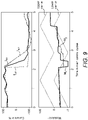
- Figure 9 shows current and modulation waveforms. It can be assumed that a current reference signal I ref is directly given by the main controller 74 or calculated through a particular local controller (e.g., local controller 72 1 ) using current reference information provided by the main controller. (In practice, it will be understood that all of the other local controllers ..., 72 q will also be calculating a corresponding current reference signal for the independent current control of their associated converter units.) As shown in Figure 9 , the current reference signal I ref includes a step-change. Two current feedback signals I fb1 and I fb2 are shown. The current feedback signals I fb1 and I fb2 are indicative of the measured current in the converter arm 50 for different local control cycle periods.
- the modulation waveform shows upper and lower triangular carrier waveforms for a particular submodule (e.g., submodule 52 1 ).
- a first modulation signal M 1 is calculated by the local controller 72 1 operated with a local control cycle with a first period.
- a second modulation signal M 2 is calculated by the local controller 72 1 operated with a local control cycle with a second period that is about twice that of the first period.
- the modulation signal is provided to the first PWM generator 96 1 to generate the gate drive commands G 11 , G 12 , ..., G 14 for the submodule 52 1 .
- the second PWM generator 96 2 for the local controller 72 1 will receive a respective modulation signal.
- a respective modulation signal will also be calculated and provided to each PWM generator of the other submodules 52 2 , ..., 52 n .
- the upper and lower carrier waveforms for each PWM generator will be phase shifted as described above to provide distributed current control.
- the current waveform shows how the converter arm current responds differently depending on whether the local controller 72 1 is operated with the first local control cycle or the second local control cycle.
- the first current feedback signal I fb1 (first local control cycle) tracks the current reference I ref significantly better than the second current feedback signal I fb2 (second local control cycle with the longer period) in response to the step-change.
- the first modulation index M 1 also shows a significantly more dynamic response than the second modulation index M 2 . It can therefore be seen that a significant improvement is achieved by operating the local controller 72 1 with a shorter local control cycle period.
- centralised current control where a current control signal is calculated by the main controller and transmitted to each local controller would have an even longer control cycle period (e.g., 40-100 ⁇ s) and would therefore be even less dynamic than the second control cycle.
Abstract
Description
- The present invention relates to power converters, and in particular to voltage source converters (VSCs) that include a plurality of series-connected converter units operated with distributed current control.
- The VSCs can be modular multi-level converters (MMCs) where the converter units are submodules that are connected together in series to define a converter arm of the MMC. The series-connected converter units can also be conventional VSCs such as two-level or multi-level converters with separate power supply infeed, for example.
- MMCs are well known for various medium- and high-power applications and have been implemented as voltage source converters (VSCs) for:
- high voltage direct current (HVDC) transmission systems,
- variable speed drives (VSDs), e.g., for driving electrical machine and other electrical loads,
- direct AC/AC power conversion, e.g., for supplying AC power to the overhead line of electric rail networks or industrial equipment, and
- static synchronous compensators (STATCOMs) for regulating AC transmission networks, for example.
- A typical MMC includes at least one converter arm with a plurality of series-connected submodules (sometimes called switching modules) and an inductor. The submodules can have any suitable topology such as half-bridge, full-bridge, cross-connected, mixed-cell etc. as will be known to the skilled person. Each submodule normally has at least two controllable semiconductor switches and an energy storage device (e.g., a capacitor). In some arrangements, the semiconductor switches are connected in series and the energy storage device is connected in parallel with the series-connected semiconductor switches. According to the switching state of each submodule - as determined by the switching state of the individual semiconductor switches - the converter arm current will either charge/discharge the energy storage device or bypass the energy storage device so that its voltage is maintained. The MMC will typically have a plurality of converter arms arranged in parallel - for example converter arms may be connected in parallel between a pair of DC buses with each converter phase having an upper arm with one or more submodules and a lower arm with one or more submodules and defining an AC bus therebetween, or each converter arm may be connected at one end to a respective AC bus and connected to each other (e.g., in a star or delta configuration) or to another respective AC bus at the other end.
- Because an MMC typically includes a large number of submodules, controlling the MMC using one main controller involves exchanging a large amount of data with the submodules or their local controllers for voltage balancing, protection settings, fault information and the control of the overall converter outputs, for example. The requirement to use communication protocols that are suitable for exchanging the large amount of data, and the need for the main controller to carry out the necessary calculations for converter current control for the various submodules, requires a certain amount of time, which in turn limits the dynamic response of the MMC. Accordingly, any reduction in the direct communication between the main controller and the submodules or their local controllers can reduce the required communication time and significantly improve the control dynamics. Introducing distributed current control can also reduce the computation demands on the main controller, leading to a further improvement in control dynamics.
- As mentioned above, one or more local controllers are normally used to control the switching state of the submodules in a converter arm to carry out current and voltage balancing control. In particular, the local controllers can typically balance the energy of the energy storage devices by using certain switching states that increase, decrease or maintain the DC voltage of the submodules in order to balance and equalise the charge levels of the submodules in the converter arm. Each submodule can have its own local controller. Or a group of two or more submodules in the converter arm can be controlled together by a local controller. As mentioned above, each local controller can control the switching state of each associated submodule or group of submodules by controlling the switching state of the individual semiconductor switches - i.e., by controlling the individual semiconductor switches to switch to an on- or off-state as required to either charge/discharge the energy storage device or bypass the energy storage device. Each local controller can use pulse width modulation (PWM) to generate gate drive commands which are supplied to the respective gate drive unit of the semiconductor switches of each associated submodule or group of submodules. Each local controller can generate the gate drive commands according to the desired switching states of each associated submodule or group of submodules. The gate drive commands can be calculated by a respective PWM generator in response to a modulation signal. The modulation signal for each submodule can be derived to provide both current and voltage balancing control. Each modulation signal is compared with a carrier waveform to derive the gate drive commands in a known manner. Alternatively, nearest level control or sorting-based methods can be used to control the output voltage of the submodules.
- Each modulation signal can be derived using a current control signal (and other signals such as a voltage balancing signal and a voltage reference signal, for example). Each local controller receives the current control signal from a main controller, e.g., a controller for the converter arm or the MMC. The current control signal is typically calculated by the main controller using a current feedback signal that is received by the main controller. The main controller typically has a control cycle time of about 100µs. Once a value for the current feedback signal is received by the main controller during a particular control cycle, it must typically wait until the next control cycle before using the received current feedback value to calculate the value of the current control signal, and then transmit the calculated current control signal value to the local controllers. This results in a significant control delay, e.g., up to 200µs in some arrangements.
- Current control is centralised because the local controllers can only carry out current control for the submodule or group of submodules using the current control signal that is calculated and transmitted by the main controller for the converter arm or MMC. VSCs are well known and typically comprise first and second DC terminals and one or more AC terminals. When operated as an inverter, the VSC can convert a DC input voltage at the first and second DC terminals to an AC output voltage at the AC terminal(s). In practice, the VSC comprises a plurality of controllable semiconductor switches that can be switched between an on-state and an off-state as required to synthesise the AC output voltage. The VSC can be a two-level or multi-level converter, for example. Suitable topologies for a multi-level converter include neutral point piloted (NPP) and neutral point clamped (NPC).
- A plurality of known VSCs can be connected together in series - for example, to achieve a specific level of voltage, current or output power.
- The present invention provides a power converter comprising:
- a plurality of series-connected converter units, each converter unit comprising a plurality of semiconductor devices, each semiconductor device including at least a controllable semiconductor switch (e.g., an IGBT);
- a plurality of synchronised local controllers, each local controller being associated with at least one converter unit;
- a current sensor providing a current feedback signal directly to at least one of the plurality of local controllers, the current feedback signal being indicative of a converter current; and
- a main controller providing a current reference signal, or current reference information for calculating a current reference signal, to the at least one local controller each "main control cycle" (i.e., the control cycle of the main controller), the current reference signal being indicative of a desired converter current;
- wherein the at least one local controller is adapted to operate individually to:
- optionally use the current reference information to calculate the current reference signal; and
- carry out current control for the associated at least one converter unit on the basis of the current feedback signal and the current reference signal each "local control cycle" (i.e., the control cycle of each local controller); and
- wherein the plurality of local controllers are synchronised to operate together as a single controller for distributed current control of the plurality of series-connected converter units.
- The present invention further provides a method of operating a power converter comprising:
- a plurality of series-connected converter units, each converter unit comprising a plurality of semiconductor devices, each semiconductor device including at least a controllable semiconductor switch (e.g. an IGBT); and
- a plurality of synchronised local controllers, each local controller being associated with at least one converter unit;
- the method comprising the steps of:
- providing a current feedback signal directly to at least one of the plurality of local controllers, the current feedback signal being indicative of a converter current;
- providing a current reference signal or current reference information for calculating a current reference signal to the at least one local controller each main control cycle, the current reference signal being indicative of a desired converter current;
- the at least one local controller optionally using the current reference information to calculate the current reference signal;
- the at least one local controller independently carrying out current control for the associated at least one converter unit on the basis of the current feedback signal and the current reference signal each local control cycle; and
- the plurality of local controllers being synchronised to operate together as a single controller for distributed current control of the plurality of series-connected converter units.
- The fact that the at least one local controller receives the current feedback signal directly from the current sensor can be contrasted with the centralised current control for the submodules of the modular multi-level converter (MMC) described above, where a current control signal is calculated by the main controller and transmitted to each local controller during each control cycle of the main controller. The present invention provides rapid current control that is distributed through the local controllers. Delay times caused by data conversion and processing of intermediate devices such as the main controller or distribution panels is minimised, which gives a faster response time.
- In practice, the period of the local control cycle can be less than about 10µs, which can result in a control response that is almost analogue.
- The period of the main control cycle can be about 40-100µs. The period of the local control cycle is preferably significantly shorter than the main control cycle - and is typically at least less than half of the period of the main control cycle.
- The series-connected converter units are controlled by synchronised local controllers. Each local controller is adapted to operate individually for the current control of its associated at least one converter unit. The synchronisation of the local controllers ensures that the local controllers operate together as a single (or aggregate) controller for distributed current control. In particular, although each local controller is adapted to independently carry out current control for the associated at least one converter unit, the local controllers are operated with time-based synchronisation in order to derive a desired converter current waveform. The desired converter current waveform is derived from the output voltage of each individual converter unit in conjunction with an impedance or arm inductor as described in more detail below. In particular, the different output voltages of the converter units contribute to the overall current control. It will be readily understood that the amount of information that needs to be exchanged between the main controller and the local controllers is significantly reduced, which improves control dynamics.
- Unless otherwise stated, any reference herein to components being "connected" includes both a direct and an indirect electrical connection or coupling, e.g., with the option for components to be electrically connected or coupled together by means of one or more interposing components.
- Any reference herein to a "signal" includes a series of discrete values transmitted between components of the power converter or calculated by a component such as a local controller.
- As used herein, "distributed current control" refers to the current control that is carried out by the synchronised local controllers acting as a single (aggregate) controller so that the series-connected converter units are controlled together in a synchronised and coordinated manner to derive a desired converter current. This distributed current control is intended to replicate the current control that would have previously been carried out by the main controller, but with significantly improved control dynamics, faster response times etc.
- In each converter unit, each semiconductor device may further include an anti-parallel connected diode, i.e., a diode connected in anti-parallel with its associated controllable semiconductor switch. Controllable semiconductor switches that normally include an anti-parallel connected diode would include insulated-gate bipolar transistors (IGBTs), for example.
- The converter units can be connected in series with at least one inductor.
- The power converter can be a voltage source converter (VSC) implemented as an MMC where the converter units are normally called submodules. The plurality of series-connected submodules can define a converter arm of the MMC. The converter arm can also include an inductor. The current feedback signal can be indicative of the converter arm current, i.e., the current flowing in the converter arm, and the current reference signal or information can be indicative of the desired converter arm current. The MMC can include a plurality of converter arms, which can be connected together and/or to any external circuit or load in any suitable arrangement as will be known to the skilled person.
- Each submodule can include an energy storage device (e.g., a capacitor).
- The submodules can be considered to be individual VSCs and can have any suitable topology such as half-bridge, full-bridge, cross-connected, mixed-cell etc. as will be known to the skilled person. Typically, each submodule will include at least two controllable semiconductor switches connected in series and an energy storage device (e.g., a capacitor) connected in parallel with the series-connected semiconductor switches. In a full-bridge topology, each submodule comprises a first leg with two controllable semiconductor switches connected in series and a second leg with two controllable semiconductor switches connected in series. The first and second legs are connected in parallel between first and second DC rails. An energy storage device (e.g., a capacitor) is connected between the first and second DC rails in parallel with both the first and second legs. If the submodule includes an auxiliary power supply, it can be connected between the first and second DC rails in parallel with the energy storage device and the first and second arms. A junction of the semiconductor switches in the first leg defines a first AC terminal and a junction of the semiconductor switches in the second leg defines a second AC terminal.
- The MMC may be utilised for a wide variety of medium- and high-power applications and the converter arms may be configured accordingly for connection to an external power system, including a transmission system or power grid, and/or to an electrical load if the MMC is configured for power conversion. The converter arms may be connected together, e.g., in a delta or star configuration, if the MMC is configured as a static synchronous compensator (STATCOM). The MMC may have any suitable overall topology. The present invention is particularly applicable for MMCs that benefit from rapid current control such as voltage source converters (VSCs) for:
- high voltage direct current (HVDC) transmission systems,
- variable speed drives (VSDs), e.g., for driving electrical machine and other electrical loads,
- direct AC/AC power conversion, e.g., for supplying AC power to the overhead line of electric rail networks or industrial equipment,
- dynamic static var compensators (DSVCs) for compensation of harmonic generators such as industrial loads, and
- static synchronous compensators (STATCOMs) for regulating AC transmission or distribution networks, for example.
- The distributed current control provided by the present invention is beneficial during normal operation of the MMC by providing improved disturbance rejection, active filtering and the control of higher order current harmonics, for example. During imbalanced or disturbed operation of the MMC, the distributed current control can additionally provide improved rebalancing of the energy storage devices of the submodules. During fault conditions of the MMC, the distributed current control can provide improved control of fault currents. Additionally, the communication effort between the main controller and the local controllers is significantly reduced as rebalancing of the energy storage devices and current control is carried out locally by the local controllers.
- The power converter can be a VSC where the converter units can be implemented as individual VSCs.
- When implemented as individual VSCs, each converter unit can include a plurality of legs. Each leg can include two or more controllable semiconductor switches and define an AC terminal of the converter unit. Each leg can be connected in parallel between first and second DC rails. The converter units can be two-level or multi-level converters, for example. Suitable topologies for a multi-level converter include neutral point piloted (NPP) and neutral point clamped (NPC). But it will be readily understood that any suitable topology as will be well known to the skilled person can be used.
- Each individual VSC can include an energy storage device (e.g., a capacitor) that is charged using an external power source or separate power supply infeed. The energy storage device can be connected between the first and second DC rails in parallel with the plurality of legs.
- In one arrangement, the power supply infeed can include a power converter that is connected to first and second DC rails of the respective VSC. The power converter can be a diode bridge or an active rectifier such as a two-level or multi-level converter, for example. In one arrangement, the AC-side of each power converter can be connected to a respective output winding of a transformer so that the individual VSCs are insulated from each other. In other words, the transformer can have a plurality of output windings that can be inductively coupled to an input winding. The input winding of the transformer can be connected to an external power system. It will be readily understood that other power supply infeed arrangements are possible.
- The corresponding submodules of the MMC do not include such a power supply infeed and are therefore often described as being "floating".
- The power converters implemented using individual VSCs can be used as:
- VSCs for high voltage direct current (HVDC) transmission systems, and
- variable speed drives (VSDs), e.g., for driving electrical machine and other electrical loads, for example.
- As described in more detail below, the converter units (or submodules in the case of an MMC) can be connected in series on the AC-side (i.e., with a series connection between respective AC terminals) or on the DC-side (i.e., with a series connection between respective DC terminals or rails). A series connection on the AC-side can derive an output voltage that includes an AC component and optionally also a DC component.
- The converter units (or submodules) can be connected in series on the AC-side. If each converter unit includes a first leg defining a first AC terminal and a second leg defining a second AC terminal, at least one of the first and second AC terminals of each converter unit can be connected to an AC terminal of an adjacent converter unit to define a converter arm. If the converter arm includes n converter units, the first AC terminal of the first converter unit in the series (i.e., the converter unit at a first end of the converter arm) can be connectable to an AC bus or a DC bus - e.g., forming part of an external power system. The second AC terminal of the nth converter unit in the series (i.e., the converter unit at a second end of the converter arm) can be connectable to an AC bus or a DC bus - e.g., forming part of an external power system - or to another converter arm of the power converter. For all other converter units (i.e., where n=1, 2, ..., (n-1)) the second AC terminal of the respective converter unit is connected to the first AC terminal of the next converter unit in the converter arm. That is, the second AC terminal of the first converter unit is connected to the first AC terminal of the second converter unit, the second AC terminal of the second converter unit is connected to the first AC terminal of the third converter unit, the second AC terminal of the third converter unit is connected to the first AC terminal of the fourth converter unit, and so on, until the (n-1)th converter unit.
- The converter units can be connected in series on the DC-side. If each converter unit includes first and second DC rails defining first and second DC terminals, at least one of the first and second DC terminals of each converter unit can be connected to a DC terminal of an adjacent converter unit. If the power converter includes n converter units, the first DC terminal of the first converter unit in the series can be connectable to a DC bus - e.g., forming part of an external power system. The second DC terminal of the nth converter unit in the series can be connectable to another DC bus - e.g., forming part of an external power system. For all other converter units (i.e., where n=1, 2, ..., (n-1)) the second DC terminal of the respective converter unit is connected to the first DC terminal of the next converter unit in the series. That is, the second DC terminal of the first converter unit is connected to the first DC terminal of the second converter unit, the second DC terminal of the second converter unit is connected to the first DC terminal of the third converter unit, the second DC terminal of the third converter unit is connected to the first DC terminal of the fourth converter unit, and so on, until the (n-1)th converter unit. Each converter leg of each converter unit can define an AC terminal. The AC terminals of the converter units can be connected together or combined on the AC-side, e.g., using a transformer, multi-stage transformer or interface reactors.
- In each case, the current feedback signal can be indicative of the converter arm current, i.e., the current flowing in the series-connected converter units, and the current reference signal or current reference information can be indicative of the desired converter arm current. Alternatively, the current feedback signal can be indicative of a different converter current, e.g., the current flowing into or out of the power converter as a whole.
- The main controller can be a controller for the power converter or for the converter arm. The main controller can have any suitable implementation.
- Each local controller can be associated with one converter unit of the power converter. But in practice, it is likely that each local controller will be associated with two or more converter units of the power converter that can be controlled together as a group.
- In one arrangement, all of the local controllers will receive the current feedback signal directly from the current sensor. In an alternative arrangement, the at least one local controller that receives the current feedback signal directly from the current sensor can send the current feedback signal to one or more other local controllers (so-called "daisy chain" arrangement).
- The local controllers can be implemented as programmable logic devices (e.g., complex programmable logic devices (CPLDs) or field programmable gate arrays (FPGAs) that are semiconductor devices that are based around a matrix of configurable logic blocks). The programmable logic devices should support parallel processing to facilitate calculation, sending and receiving of data and the sending of gate drive commands to control the switching of the semiconductor switches of each associated converter unit as parallel processes. The local controllers can also be implemented as digital signal processors (DSPs) or as micro or multicore processing units, for example. Each local controller can use pulse width modulation (PWM) or any other suitable control strategy to generate the gate drive commands which are supplied to the respective gate drive unit of the semiconductor switches of each associated converter unit.
- The current sensor can be implemented as one or more digital interfaces that are associated with at least one analogue current transducer for measuring the converter current. The current sensor can include an analogue-to-digital converter, which can be implemented as part of the analogue current transducer or as a separate device.
- The analogue-to-digital converter can convert the analogue current measurements from the current transducer into the current feedback signal which is then transmitted as data with or without a suitable protocol header. The current feedback signal can be transmitted in parallel using multiple channels, e.g., where the same data is transmitted in parallel to each local controller at the same time using a respective signal connection such as a fibre optic cable - see below. The current feedback signal can include a synchronisation signal or data for synchronising the local controllers.
- The current sensor can also be integrated into a local controller - or put another way, the current sensor can have the additional functionality of a local controller and can generate gate drive commands for associated converter units. Component parts of the current sensor can be co-located or distributed through the power converter. In particular, the current transducer and the analogue-to-digital converter can be separate devices that are separately located and connected by a suitable connection. Just the analogue-to-digital converter can be integrated into another component such as a local controller or the main controller, for example.
- One or more of the local controllers can be directly connected to the current sensor by a suitable signal connection which allows the current feedback signal to be received from the current sensor. In one arrangement, each local controller is directly connected to the current sensor by its own signal connection so that the same data can be transmitted in parallel to each local controller at the same time. But the local controllers can also be directly connected to the current sensor by a bus-type signal connection with a suitable protocol. In the case of a daisy chain arrangement, pairs or groups of two or more local controllers can be connected together by a suitable signal connection which allows the current feedback signal to be propagated to all local controllers in the converter arm without significant delay once it has been received by the at least one local controller.
- In one arrangement, the signal connection can be a fibre optic cable which allows the current feedback signal to be transmitted as a series of values using a suitable protocol, e.g., a short protocol with a minimum overhead framework, and with a protocol header. A suitable protocol would be one that uses 4B5B line code or other self-clocking line code, for example.
- In the case of a power converter with a plurality of series-connected converter units, it is not straight-forward to connect each local controller to a single current sensor using an electrical (or wired) connection as the signal connection. This is because the converter units and their associated local controllers are effectively tied to different potentials. A conventional electrical connection would therefore provide a galvanic coupling between the converter units and the current sensor. A fibre optic cable can provide a galvanically-insulated connection that can be used to connect the current sensor to all of the local controllers in a preferred arrangement. However, it is possible to use an electrical connection as the signal connection if all DC voltage measurements, communication lines or cables, and the power supplies of the local controllers are galvanically isolated from the converter units - e.g., if any voltage feedback signals are transmitted from the converter units to the associated local controller through fibre optic cables as a galvanically-insulated connection.
- The signal connection to the current sensor or between the local controllers can include two or more fibre optic cables or electrical connections in parallel for redundancy.
- In one arrangement, the signal connection can be a wireless connection using any suitable wireless protocol.
- The local controllers can receive one or more additional signals or information from the current sensor such as:
- a synchronisation signal if this is not integrated with the current feedback signal, and
- a signal indicative of fault status, e.g., a trip signal or a failure signal. Such a signal can include information that allows it to be selectively applied by individual local controllers so that one or more local controllers can be controlled to stop generating gate drive commands for the associated converter units and/or one or more other local controllers can be controlled to put the associated converter units into a bypass switching state, for example. Information indicative of a fault status can also be included in any protocol header for the current feedback signal.
- The main controller can receive the current feedback signal directly from the current sensor or from one of the local controllers. The main controller can be connected to the current sensor by a suitable signal connection which allows it to receive the current feedback signal. In one arrangement, the main controller is directly connected to the current sensor by its own signal connection - in parallel with the signal connections that directly connect each local controller to the current sensor - so that the same data can be transmitted in parallel to the main controller and to each local controller at the same time. But the main controller can also be directly connected to the current sensor by a bus-type signal connection with a suitable protocol.
- The signal connection can be a fibre optic cable, an electrical (or wired) connection, or a wireless connection using any suitable wireless protocol, for example.
- The signal connection can include two or more fibre optic cables or electrical connections in parallel for redundancy.
- In some arrangements, the main controller can use the signal connection to send one or more signals to the current sensor, e.g., a signal for controlling the synchronisation of the local controllers, a signal for generating a trip/failure status etc. Any additional signals can be transmitted from the main controller to the current sensor using a suitable protocol, e.g., an ethernet-based protocol operating within the main control cycle.
- The local controllers can be connected to the main controller by a suitable signal connection which allows the local controllers to receive the current reference signal or current reference information. The signal connection can also allow other signals or information to be transferred between the local controllers and the main controller - see below. Any signals can be transmitted between the main controller and the local controllers using a suitable protocol, e.g., an ethernet-based protocol operating within the main control cycle.
- The signal connection can be a fibre optic cable, an electrical (or wired) connection, or a wireless connection using any suitable wireless protocol, for example.
- The signal connection can include two or more fibre optic cables or electrical connections in parallel for redundancy.
- The current control for each associated converter unit can be carried out using a current control signal that is calculated locally by each local controller. In particular, the calculated current control signal can be used to derive a modulation signal (or modulation index). The modulation signal is used by a respective PWM generator to generate gate drive commands for the semiconductor switches of each associated converter unit. Gate drive commands are generated for each associated converter unit and put each semiconductor switch in a particular switching state. The switching states of the individual semiconductor switches define a switching state for the converter unit - which in turn defines the output voltage of the individual converter unit. The output voltage is used to control the current under consideration of an impedance or arm inductor according to conventional control principles of single VSCs.
- Within each PWM generator, the modulation signal can be compared with at least one carrier waveform to derive the gate drive commands in a known manner. Any suitable carrier waveform can be used such as a triangular waveform, sawtooth waveform etc. Two or more carrier waveforms can be used if the series-connected converter units are multi-level converters in order to generate the various output voltage levels. The carrier waveforms for each of the series-connected converter units are shifted (e.g., phase-shifted or level-shifted) to generate uniformly distributed switching events. The PWM generators can use phase-shifted carrier PWM or phase disposition PWM, for example. The shift in the carrier waveforms corresponds to the shift that would be applied if the current control was carried out by the main controller in a known manner, but without the need to exchange significant amounts of information that limits control dynamics. The preferably uniform distribution of related switching events is defined by the carrier shift information provided by the main controller and the synchronization of the local controllers. This allows the local controllers to individually control the converter arm current based on the same measured current feedback signal with a common impedance or arm inductor.
- Each local controller can include a current controller which calculates the current control signal. The current controller can have any suitable topology and can include one or more sub-controllers such as proportional-integral (or PI) controller or proportional-resonant (or PR) controllers, for example.
- In one arrangement, the main controller can transmit a current reference signal to each local controller.
- In another arrangement, the main controller can transmit current reference information to each local controller. Each local controller can then use the current reference information to locally calculate a current reference signal. Each local controller can include a current reference calculator which calculates the current reference signal from the current reference information provided by the main controller. The current reference information can include one or more of angle information, frequency information and amplitude information, for example.
- The current reference signal can be a series of variable values (e.g., for an AC output) or a series of constant values (e.g., for a DC output).
- The difference between the (received or locally-calculated) current reference signal and the current feedback signal can be calculated by each local controller (e.g., using a summing node) and supplied to the current controller as an input. The output of the current controller is the current control signal, which in practice is a first series of calculated voltage values that can be used to derive the modulation signal.
- Each local controller receives the current reference signal or the current reference information from the main controller each main control cycle, e.g., about every 40-100µs. The received or locally-calculated current reference signal can be continuously updated by each local controller if appropriate. Each local controller also receives a current feedback signal from the current sensor at least each local control cycle. (In some cases, the current sensor may provide two or more values of current feedback signal - and any additional signals or information - during a single control cycle of the local controller.) This means that the current controller can calculate a current control signal each local control cycle using the current feedback signal that is indicative of the converter current (e.g., the converter arm current). This, in turn, means that the modulation signal that is used by each PWM generator to generate the gate drive commands for the associated converter unit can be calculated each local control cycle. As noted above, the period of the local control cycle is typically less than about 10µs and in some cases may even be as small as 1µs to give an almost analogue control response. It can therefore be understood that the distributed current control carried out by the local controllers using the associated converter units can respond rapidly to changes in measured current on the basis of the current feedback signal received from the current sensor, with an additional response arising from changes in the current reference signal or current reference information received from the main controller each main control cycle. This additional response can include abrupt changes in current demand to which the distributed current control can respond rapidly, as well as more gradual changes in current demand.
- Each local controller can receive a voltage feedback signal from each associated converter unit that is indicative of the measured DC voltage of the converter unit. For example, if each local controller is associated with p converter units, it can receive a first voltage feedback signal from the first converter unit that is indicative of the measured DC voltage of the first converter unit, a second voltage feedback signal from the second converter unit that is indicative of the measured DC voltage of the second converter unit, ..., and an pth voltage feedback signal from the pth converter unit that is indicative of the measured DC voltage of the pth converter unit. The individual voltage feedback signals can be used by the local controller to calculate a "local" average voltage signal that is indicative of the average of the measured DC voltage of the p converter units associated with the particular local controller. Each local controller can include an average voltage calculator. The voltage feedback signals can be received by the local controller each control cycle of the local controller or multiple thereof, e.g., about every 10µs, 20µs, ..., 100µs. In practice, the DC voltages of the associated converter units can be measured faster than this, but the DC link or submodule capacitors are not typically very dynamic, and it can reduce computational overhead to coordinate the voltage feedback signals with the local control cycle. A "global" average voltage signal that is indicative of the average of the measured DC voltage of some or all of the converter units in the converter arm or the power converter as a whole can be provided to each local controller. In this arrangement, the individual voltage feedback signals or a locally-calculated average voltage signal for each local controller can be transmitted by each local controller to the main controller, for example. The main controller will use some or all of the individual feedback signals or the locally-calculated average voltage signals to calculate the "global" average voltage signal, which is then provided to each local controller each main control cycle. In an alternative arrangement, the "global" average voltage signal can be calculated by another device with a faster control cycle. For example, the current sensor could be used. The current sensor can calculate the "global" average voltage and send this back to each local controller as a series of values with a suitable protocol header.
- Voltage balancing control for each associated converter unit can be carried out using a voltage balancing control signal that is calculated locally by each local controller. In particular, the voltage balancing control signal can be used together with the current control signal that is calculated by the current controller to derive the modulation signal that is used by the respective PWM generator to generate the gate drive commands for the semiconductor switches of each associated converter unit. Each local controller can include a voltage balancing controller which calculates the voltage balancing reference signal using the voltage feedback signal from an associated converter unit and either the "local" or "global" average voltage signal as appropriate.
- If each local controller is associated with p converter units, it can include p voltage balancing controllers and p PWM generators. The difference between the "local" or "global" average voltage signal and the respective voltage feedback signal can be calculated (e.g., using a respective summing node) and supplied to the respective voltage balancing controller as an input. For example, the difference between the "local" or "global" average voltage signal and the first voltage feedback signal for the first converter unit can be calculated (e.g., using a first summing node) and supplied to a first voltage balancing controller as an input, the difference between the "local" or "global" average voltage signal and the second voltage feedback signal for the second converter unit can be calculated (e.g., using a second summing node) and supplied to a second voltage balancing controller as an input, ..., the difference between the "local" or "global" average voltage signal and the pth voltage feedback signal for the pth converter unit can be calculated (e.g., using a pth summing node) and supplied to a pth voltage balancing controller as an input.
- The output of the respective voltage balancing controller is the voltage balancing control signal which in practice is a second series of calculated voltage values. The respective voltage balancing control signal can be added to the current control signal from the current controller, e.g., using a respective summing node, the output of which is the modulation signal that is used by the respective PWM generator to generate the gate drive commands for the gate drivers of the controllable semiconductor switches. For example:
- a first voltage balancing control signal from the first voltage balancing controller can be added to the current control signal from the current controller, e.g., using a first summing node, the output of which is a first modulation signal that is used by a first PWM generator to generate the gate drive commands for the semiconductor switches of the first converter unit,
- a second voltage balancing control signal from the second voltage balancing controller can be added to the current control signal from the current controller, e.g., using a second summing node, the output of which is a second modulation signal that is used by a second PWM generator to generate the gate drive commands for the semiconductor switches of the second converter unit, ...,
- a pth voltage balancing control signal from the pth voltage balancing controller can be added to the current control signal from the current controller, e.g., using a pth summing node, the output of which is a pth modulation signal that is used by a pth PWM generator to generate the gate drive commands for the semiconductor switches of the pth converter unit.
- The carrier waveforms for the first, second, ..., pth PWM generator of the local controller are phase-shifted or level-shifted and this is extended to the carrier waveforms for the PMW generators of the remaining local controllers so that all of the carrier waveforms are phase-shifted or level-shifted with respect to each other to generate uniformly distributed switching events for the series-connected converter units of the power converter.
- Each local controller can also receive a voltage reference signal or voltage reference information from the main controller each main control cycle. The voltage reference signal is a third series of voltage values that is indicative of the output voltage waveform and can be added to the first and second voltage values (i.e., to the current and voltage balancing control signals) to derive the respective modulation signal, e.g., using the respective summing node. Each modulation signal is therefore indicative of the sum of the individual voltage values and is used to achieve the required output voltage with the desired current and voltage balancing control.
- The main controller can transmit the voltage reference signal to each local controller.
- In another arrangement, the main controller can transmit voltage reference information to each local controller. Each local controller can then use the voltage reference information to locally calculate a voltage reference signal. Each local controller can include a voltage reference calculator which calculates the voltage reference signal from the voltage reference information. The voltage reference information can include one or more of angle information, frequency information and amplitude information, for example.
- The voltage reference signal can be a series of variable values (e.g., for an AC output), a series of constant values (e.g., for a DC output), or a summation thereof (e.g., for an AC output with a DC output component).
- The local controllers can continuously update or calculate the current reference signal and/or the voltage reference signal within the slower control cycle time of the main controller. For example, in one arrangement where the current reference signal and the voltage reference signal are sinusoidal signals they can be continuously updated or calculated locally by each local controller on the basis of the following information, which can be provided by the main controller each main control cycle:
- angle information at the start of the control cycle (e.g., information relating to the angle θ),
- frequency information that can be used to update the angle θ within the control cycle, and
- amplitude information (e.g., x/y or r).
- The angle information and frequency information can be used to define θ(t). The angle information might also be used for other purposes, e.g., by a proportional-resonant controller forming part of the current controller.
- If the amplitude information is defined by a single value (e.g., r) then the generic reference signal S calculated by the local controller can be represented by:


- If the amplitude information is defined by two values (e.g., x/y) then the generic reference signal S can be represented by:

- Depending on the other control functions, x/y are typically alpha/beta or d/q, for example.
- It will be readily understood that other functions could be used to calculate the current reference signal and/or the voltage reference signal if they are not sinusoidal signals.
- Each modulation signal can be divided by the respective voltage feedback signal before it is provided to the respective PWM generator. For example, the first modulation signal can be divided by the first voltage feedback signal, the second modulation signal can be divided by the second voltage feedback signal, ..., the pth modulation signal can be divided by the pth voltage feedback signal.
- Each local controller can send one or both of the voltage feedback signals and the locally-calculated average voltage signal to the main controller each local control cycle or multiple thereof. If the current sensor is connected to the main controller, one or both of the voltage feedback signals and the average voltage signal can also be transmitted by the local controllers to the current sensor and then to the main controller.
- Each local controller can receive one or more signals from the main controller each main control cycle or multiple thereof.
- The signals (or data) received from the main controller can include one or more of:
- a signal indicative of carrier waveform information for the PWM such as carrier frequency, carrier shift angle etc.,
- one or more signals for current control, e.g., a current reference signal or current reference information that can be used by each local controller to calculate a current reference signal, control parameters for the current controller such as control cycle time, proportional and/or integral gains, integrator limits, filter parameters etc.,
- one or more signals for voltage balancing control, e.g., a voltage reference signal which might be a signal indicative of the average voltage of the converter arm or the power converter (i.e., a "global" average voltage signal) or a signal indicative of control parameters for the voltage balancing controller such as control cycle time, proportional and/or integral gains, integrator limits, filter parameters etc.,
- a voltage reference signal or voltage reference information that can be used by each local controller to calculate a voltage reference signal,
- a signal indicative of the main control cycle time (e.g., a signal indicative of the start of the next control cycle when data is exchanged between the local controllers and the main controller),
- a synchronisation signal which is used to synchronise the local controllers, and
- a signal indicative of a fault status, e.g., a trip signal or a failure signal. Such a signal can include information that allows it to be selectively applied by individual local controllers so that one or more local controllers can be controlled to stop generating gate drive commands for the associated converter units and/or one or more other local controllers can be controlled to put the associated converter units into a bypass switching state, for example.
- Any suitable method can be used to synchronise the local controllers to each other and to the main controller. The purpose of the time-based synchronisation is to make sure that all of the local controllers are providing a synchronised current control output which allows the individual local controllers to act as a single (or aggregate) controller that provides distributed current control. Without accurate synchronisation of the local controllers, the local control cycles can diverge, and this can result in the local controllers creating a distorted output. Consequently, the synchronisation must make sure that the inputs for each local controller are latched at the same time - i.e., that each local controller uses the same current feedback signal, current and voltage reference signals etc.
- In one arrangement, the local controllers can be synchronised using a synchronisation signal that is transmitted by the current sensor, the main controller or a stand-alone synchronisation controller. For example, if the current sensor is connected to each local controller (i.e., through a fibre optic cable, an electrical (or wired) connection or a wireless connection) the current sensor can send a synchronisation signal to the local controllers. The sign for the synchronisation, which is used by the local controllers, can be defined by the main controller within a slower control cycle time. In the case of the "daisy chain" arrangement, the current sensor can send a synchronisation signal to the at least one local controller which will then send the synchronisation signal to one or more other local controllers without significant delay, i.e., through a fibre optic cable, an electrical (or wired) connection or a wireless connection. Alternatively, the current sensor can send the current feedback signal to the at least one local controller which will then tell the one or more other local controllers which value of current feedback signal to use for the current control (e.g., using a different protocol header). A local controller which receives the current feedback signal from the current sensor or from another local controller can be a "master" local controller and instruct one or more other local controllers (or "slave" local controllers) which value of current feedback signal to use for the current control. Each "slave" local controller can wait at each particular control cycle until the value of current feedback signal is received from a "master" local controller and can carry out the necessary calculations for local current control. If necessary, any delays introduced by the "daisy chain" arrangement can be compensated for, e.g., by using an offset parameter associated with each converter unit.
- Since current control is distributed over the plurality of local controllers, care should be taken to ensure that the local controllers operate in a coordinated manner and do not conflict with each other. For example, a situation should be avoided where one local controller controls its associated converter units to generate a large positive output voltage while another local controller controls its associated converter units to generate a large negative output voltage, which compensates for the large positive output voltage. This should be prevented by proper synchronisation of the local controllers so that they all carry out current control substantially simultaneously - i.e., that their control cycles are synchronised in time - and that they use the same current feedback signal, current reference signal and any other control parameters (e.g., any constants that may be used by individual controllers such as proportional-integral controllers). To ensure that the local controllers use the same current feedback signal it is possible to:
- send each current feedback value with a distinguishing protocol header so that the local controllers wait for the expected header to arrive, or
- only send each current feedback value at trigger moments associated with the current control.
- The current sensor can continuously update the protocol header (e.g., using a counter) before sending a current feedback value and without knowing about the particular control cycle of the local controllers. The local controllers can wait for a certain counter value and then use the corresponding value of the current feedback signal.
- Alternatively, if the current sensor knows the particular control cycle of the local controllers it can update the protocol header at each trigger moment. For example, at each trigger moment, the current feedback signal can be transmitted with a protocol header which indicates that the value is to be used for current control. Between each trigger moment, the current feedback signal can be transmitted with a different header which indicates that the value is to be used for other functions - i.e., for functions other than current control. This can minimise the time during which the local controllers wait for the feedback current values to be received - the delay is substantially equal to the communication time.
- Each local controller can also send a request signal to the current sensor for each trigger moment with the current sensor subsequently sending a current feedback value in response to a request signal to all local controllers with a distinguishing protocol header.
-
-
Figure 1 shows a first power converter according to the present invention implemented as a variable speed drive (VSD); -
Figure 2 shows a second power converter according to the present invention implemented as an AC/AC converter; -
Figures 3 and4 show a third power converter according to the present invention implemented as a static synchronous compensator (STATCOM); -
Figure 5 shows a first converter arm for a power converter according to the present invention implemented as a multi-level modular converter (MMC) with a plurality of series-connected submodules; -
Figure 6 shows a second converter arm for a power converter according to the present invention with a plurality of series-connected voltage source converters (VSCs); -
Figure 7 shows a current sensor, main controller and local controllers for controlling a converter arm of an MMC according to the present invention; -
Figure 8A shows a first arrangement of a local controller; -
Figure 8B shows a second arrangement of a local controller; and -
Figure 9 shows current and modulation waveforms for the operation of a power converter according to the present invention. -
Figure 1 shows a power converter implemented as a variable speed drive (VSD). - The power converter includes three
converter arms buses 4, 6. Each converter arm is divided into an upper arm and a lower arm. Each upper arm includes n series-connected converter units (or submodules) 81, 82, ..., 8n and each lower arm includes n series-connected converter units (or submodules) 101, 102, ..., 10n, where n is any suitable integer. Each converter arm includes an inductor. - The connection between the upper arm and the lower arm of the
first converter arm 21 defines a first alternating current (AC)bus 12. The connection between the upper arm and the lower arm of thesecond converter arm 22 defines asecond AC bus 14. The connection between the upper arm and the lower arm of thethird converter arm 23 defines athird AC bus 16. The first, second andthird AC buses second DC buses 4 and 6 can be connected to a DC load or a DC supply and can include a DC link with one or more energy storage devices (e.g., capacitors). - The power converter can convert a DC input voltage to an AC output voltage or vice versa by operating the
converter units 82,..., 8n and 102, ..., 10n in a manner well known to the skilled person. -
Figure 2 shows a power converter implemented as an AC/AC converter. The power converter includes sixconverter arms fourth converter arms first AC bus 20 at a first end. The second andfifth converter arms sixth converter arms third AC bus 24 at a first end. The first, second andthird converter arms fourth AC bus 26 at a second end. The fourth, fifth andsixth converter arms - Each
converter arm - The power converter can convert a three-phase AC input voltage to a single-phase AC output voltage at a different frequency by operating the
converter units 302, ..., 30n. In one example, the power converter can be used to supply AC power from a power grid operating at 50 Hz to the overhead line of an electric rail network operating at 16.7 Hz. -
Figures 3 and4 show a power converter implemented as a static synchronous compensator (STATCOM). - Each power converter includes three converter arms 321, 322 and 323. The first converter arm 321 is connected to a
first AC bus 34 at a first end. The second converter arm 322 is connected to asecond AC bus 36 at a first end. The third converter arm 323 is connected to athird AC bus 38 at a first end. - In the power converter shown in
Figure 3 , the first, second and third converter arms 321, 322 and 323 are connected together in a star configuration at their second ends. In the power converter shown inFigure 4 , the first, second and third converter arms 321, 322 and 323 are connected together in a delta configuration at this second ends. - Each converter arm 321, 322 and 323 includes n series-connected converter units (or submodules) 401, 402, ..., 40n, where n is any suitable integer. Each converter arm includes an inductor.
- By operating the
converter units 402, ..., 40n the power converter can act as a source or sink of reactive AC power for regulating an AC transmission network, for example. -
Figure 5 shows a genericfirst converter arm 50 that can be utilised in any of the power converters shown inFigures 1 to 4 when implemented as a modular multi-level converter (MMC). Theconverter arm 50 includes n series-connected submodules - Each
submodule - The first and second arms are connected in parallel. An energy storage device (e.g., a capacitor C) is connected in parallel with both the first and second legs. The semiconductor switches S1, S2, ..., S4 of each submodule 521, 522, ..., 52n are controlled by respective gate drive commands G11, G12, G13, G14, G21, G22, ..., Gn4 as shown to be switched between an on-state and an off-state (i.e., turned on and off) to selectively charge, discharge or bypass the capacitor C.
- A junction of the semiconductor switches S1 and S2 in the first leg defines a
first AC terminal 54 and a junction of the semiconductor switches S3 and S4 in the second leg defines asecond AC terminal 56. - The
first AC terminal 54 of the submodule 521 (i.e., the submodule at a first end of the converter arm 50) is connected to an AC bus or a DC bus as shown inFigures 1 to 4 . The second AC terminal of the nth submodule 52n (i.e., the submodule at a second end of the converter arm 50) is connected to an AC bus or a DC bus - as shown inFigures 1 and2 - or to another converter arm of the MMC as shown inFigures 3 and4 . For allother submodules second AC terminal 56 of thefirst submodule 521 is connected to the first AC terminal of thesecond submodule 522, the second AC terminal of thesecond submodule 522 is connected to the first AC terminal of the third submodule, and so on, until then th submodule 52n. - Each
submodule voltage sensor 58 which provides a respective voltage feedback signal Vfb1, Vfb2, ..., Vfbn. -
Figure 6 shows a genericsecond converter arm 60 that can be utilised in any of the power converters shown inFigures 1 to 4 . Theconverter arm 60 includes n series-connectedconverter units - Each
converter unit converter unit - The first and second legs are connected in parallel. A junction of the semiconductor switches S1 and S2 in the first leg defines a
first AC terminal 64 and a junction of the semiconductor switches S3 and S4 in the second leg defines asecond AC terminal 66. - An energy storage device (e.g., a capacitor C) is connected in parallel with both the first and second legs. The energy storage device of each
converter unit power supply infeed power converter power converter Figure 6 . - The
first AC terminal 64 of the converter unit 621 (i.e., the converter unit at a first end of the converter arm 60) is connected to an AC bus or a DC bus as shown inFigures 1 to 4 . The second AC terminal of the nth converter unit 62n (i.e., the converter unit at a second end of the converter arm 60) is connected to an AC bus or a DC bus - as shown inFigures 1 and2 - or to another converter arm as shown inFigures 3 and4 . For allother converter units second AC terminal 56 of thefirst converter unit 621 is connected to the first AC terminal of thesecond converter unit 622, the second AC terminal of thesecond converter unit 622 is connected to the first AC terminal of the third converter unit, and so on, until then th converter unit 62n. - Each
converter unit -
Figure 7 shows how the genericfirst converter arm 50 for an MMC is controlled. The MMC includes n series-connected submodules converter units - The
first converter arm 50 includes aninductor 53 as shown. - The MMC includes a
current sensor 70 providing a current feedback signal Ifb indicative of the converter arm current, i.e., the current flowing in theconverter arm 50. Thecurrent sensor 70 includes an analogue current transducer and an analogue-to-digital converter which converts the analogue measurements from the current transducer into the digital current feedback signal Ifb. - The MMC includes q local controllers 721, ..., 72q, where q is any suitable integer. The local controllers 721, ..., 72q are implemented as programmable logic devices that support parallel processing to facilitate calculation, sending and receiving of data and the sending of gate drive commands to control the switching of the semiconductor switches of each associated submodule as parallel processes - see below. In the arrangement shown in
Figure 7 , each local controller 721, ..., 72q is used to control two submodules (e.g., p=2). In particular, the first local controller 721 controls thesubmodules submodules submodule 521 and gate drive commands G21, G22, ..., G24 for controlling the switching of the semiconductor switches of thesubmodule 522, respectively. The qth local controller 72q generates gate drive commands G(n-1)1, G(n-1)2, ..., G(n-1)4 for controlling the switching of the semiconductor switches of thesubmodule 52(n-1) and gate drive commands Gn1, Gn2, ..., Gn4 for controlling the switching of the semiconductor switches of thesubmodule 52n, respectively. - Each local controller 721, ..., 72q receives voltage feedback signals Vfb1, Vfb2, ..., Vfbn from its associated
submodules voltage sensor 58 of thesubmodule 521 and a voltage feedback signal Vfb2 from the voltage sensor of thesubmodule 522. The qth local controller 72q receives a voltage feedback signal Vfb(n-1) from thevoltage sensor 58 of thesubmodule 52(n-1) and a voltage feedback signal Vfbn from the voltage sensor of thesubmodule 52n. - The MMC includes a
main controller 74 which transmits signals indicative of current reference information to each local controller 721, ..., 72q each control cycle of the main controller. The current reference information is indicative of a desired converter arm current and includes: - angle information (i.e., an angle θI),
- frequency information (i.e., a frequency f) that can be used to update the angle θI within the control cycle, and
- amplitude information (Id, Iq).
- The
main controller 74 also transmits signals indicative of voltage reference information to each local controller 721, ..., 72q each control cycle of the main controller. The voltage reference information is indicative of a desired voltage and includes: - angle information (i.e., an angle θV),
- frequency information (i.e., a frequency f) that can be used to update the angle θV within the control cycle,
- amplitude information (i.e., Vref_amp), and
- offset information (i.e., Vref_offset).
- The angle information for calculating the current and voltage reference signals can be the same or different.
- The current feedback signal Ifb is provided to each local controller 721, ..., 72q. Although in the arrangement shown, each local controller receives the current feedback signal Ifb directly from the
current sensor 70, in an alternative arrangement, the current feedback signal can be provided to one or more of the local controllers which can then send the current feedback signal to one or more other local controllers. For example, the current feedback signal can be provided to the first local controller 721 which can send the current feedback signal to the remaining local controllers, or to the second local controller which can send the current feedback signal to the third local controller, and so on to the qth local controller 72q (so-called "daisy chain" arrangement). - Each local controller 721, ..., 72q is connected to the
current sensor 70 by a respectivefibre optic cable 76. Thefibre optic cables 76 provide a galvanically-insulated connection which allows the current feedback signal Ifb to be transmitted as data in parallel to each of the local controllers 721, ..., 72q at the same time using a suitable protocol, e.g., a short protocol with a minimum overhead framework, and with a protocol header. - The
main controller 74 optionally also receives the current feedback signal Ifb from the current sensor 72 through a respectivefibre optic cable 76 in parallel with the local controller 721, ..., 72q. In another arrangement, the local controllers and the main controller can be connected to the current sensor by a bus-type connection. - The local controllers 721, ..., 72q are connected to the
main controller 74 by afibre optic cable 78 which is a bus-type connection. Thefibre optic cable 78 allows signals to be transmitted between the local controllers 721, ..., 72q and themain controller 74. As described above, the signals transmitted by themain controller 74 to the local controllers 721, ..., 72q include the current and voltage reference information. - The current and voltage information is transmitted to each local controller 721, ..., 72q each control cycle of the
main controller 74 using a suitable protocol, e.g., an ethernet-based protocol. - The local controllers 721, ..., 72q can also receive one or more additional signals from the
main controller 74 such as: - a signal indicative of carrier waveform information for the PWM such as carrier frequency, carrier shift angle etc.,
- control parameters for the current controller such as control cycle time, proportional and/or integral gains, integrator limits, filter parameters etc.,
- one or more signals for voltage balancing control, e.g., a voltage reference signal which might be a signal indicative of the average voltage of the converter arm or the power converter (i.e., a "global" average voltage signal),
- a signal indicative of control parameters for the voltage balancing controller such as control cycle time, proportional and/or integral gains, integrator limits, filter parameters etc.,
- a signal indicative of main controller control cycle time,
- a synchronisation signal which is used to synchronise the local controllers, and
- a signal indicative of status, e.g., a trip signal or a failure signal.
- The one or more additional signals are transmitted to each local controller 721, ..., 72q each control cycle of the
main controller 74 or multiple thereof using a suitable protocol, e.g., an ethernet-based protocol. - The
main controller 74 can also receive one or more signals from each local controller 721, ..., 72q such as: - the voltage feedback signals received from the submodules associated with each local controller and/or a locally-calculated (or "local") average voltage signal - see below, and
- a signal indicative of status.
- The one or more signals are transmitted to the
main controller 74 each control cycle of the local controller or multiples thereof using a suitable protocol, e.g., an ethernet-based protocol. -
Figure 8A shows a first arrangement of the local controller 721 which controls thesubmodules - A
current reference calculator 80 uses the current reference information transmitted by themain controller 74 to calculate and continuously update a current reference signal Iref. In particular, for an AC output, the current reference signal Lref is a sinusoidal signal represented by:
- Id is a direct-axis current amplitude,
- Iq is a quadrature-axis current amplitude, and
- θI is the rotational angle of the dq reference frame.
- The difference between the current reference signal Iref and the current feedback signal Ifb from the
current sensor 70 is calculated using a first summingnode 82. - Knowing the desired output frequency, the angle θI can be locally and continuously updated by the local controllers so that the current reference signal Iref that is used by the local controllers for current control is not constant between successive control cycles of the
main controller 74. - The output of the first summing
node 82 is provided to acurrent controller 84 which outputs a current control signal. Thecurrent controller 84 can have any suitable topology and can include one or more controllers such as proportional-integral (or PI) controllers and proportional-resonant (or PR) controllers, for example. In practice, the current control signal is a series of voltage values that are calculated by thecurrent controller 84. - The voltage feedback signals Vfb1 and Vfb2 from the respective submodules 521 and 522 are provided to an
average voltage calculator 86 which calculates a "local" average voltage signal Vav_local. - The difference between the locally-calculated average voltage signal Vav_local and the voltage feedback signal Vfb1 from the
submodule 521 is calculated using a second summingnode 881. The output of the second summingnode 881 is provided to a first voltage balancing controller 901 which outputs a first voltage balancing control signal to a third summing node 921. - The difference between the locally-calculated average voltage signal Vav_local and the voltage feedback signal Vfb2 from the
submodule 522 is calculated using a fourth summingnode 882. The output of the fourth summingnode 882 is provided to a second voltage balancing controller 902 which outputs a second voltage balancing control signal to a fifth summing node 922. - The first and second voltage balancing controllers 901 and 902 can have any suitable topology and can include one or more controllers such as proportional-integral (or PI) controllers, for example. In practice, each voltage balancing control signal is a series of voltage values that are calculated by the respective voltage balancing controller.
- The current control signal output by the
current controller 84 is provided to the third and fourth summing nodes 921 and 922 where it is added to the voltage value represented by the respective voltage balancing control signal. - A
voltage reference calculator 94 uses the voltage reference information transmitted by themain controller 74 to calculate and continuously update a voltage reference signal Vref. In particular, for an AC output, the voltage reference signal Vref is a sinusoidal signal represented by:
- Vref_amp is the amplitude of the desired output voltage,
- Vref_offset is an optional DC component of the desired output voltage, and
- θV is the rotational angle which enables the continuous update of the amplitude within the slower control cycle time of the main controller.
- In practice, the voltage reference signal Vref is a series of voltage values indicative of the desired output voltage waveform. The voltage reference signal Vref is provided to the third and fifth summing nodes 921 and 922 where it is added to the voltage values represented by the current control signal and the voltage balancing control signal.
- The output of the third summing node 921 is a first modulation signal which can be divided by the first voltage feedback signal Vfb1 and provided to a first PWM generator 961. The output of the fifth summing node 922 is a second modulation signal which can be divided by the second voltage feedback signal Vfb2 and provided to a second PWM generator 962.
- The first PWM generator 961 uses the first modulation signal to generate the gate drive commands G11, G12, ..., G14 for the semiconductor switches of the
submodule 521 and the second PWM generator 962 uses the second modulation signal to generate the gate drive commands G21, G22, ..., G24 for the semiconductor switches of thesubmodule 522. The first and second PWM generators 961 and 962 use at least one suitable carrier waveform such as a triangular or sawtooth waveform, for example. The carrier waveforms for each of thesubmodules submodules main controller 74. Phase shift information for the carrier waveforms can be transmitted to each local controller 721, ..., 72q by themain controller 74. -
Figure 8B shows a second arrangement of the local controller 721 which controls thesubmodules - The second arrangement is similar to the first arrangement of the local controller shown in
Figure 8A . The main difference is that a "global" average voltage signal Vav_global is received from themain controller 74 each control cycle of the main controller. The "global" average voltage signal Vav_global can be calculated by the main controller using individual voltage feedback signals or locally-calculated average voltage signals that are provided to the main controller by each local controller. The "global" average voltage signal can be indicative of an average voltage for the converter arm or the MMC as a whole. The "global" average voltage signal Vav_global is used in place of the "local" average voltage signal Vav_local and theaverage voltage calculator 86 is omitted from the local controllers. - In both arrangements, the local controller 721 receives the current reference information from the main controller each control cycle of the
main controller 74, e.g., about every 40-100µs, and can use the current reference information to calculate and update the current reference signal Iref. The local controller 721 receives the current feedback signal Ifb from thecurrent sensor 70 each control cycle of the local controller, e.g., about every 10µs or less. This means that thecurrent controller 84 can calculate a current control signal for each control cycle of the local controller 721. This, in turn, means that the modulation signals that are used by the respective PWM generators to generate the gate drive commands for the submodules can be calculated for each control cycle of the local controller 721. The control cycle of the local controller 721 is typically less than about 10µs and in some cases may even be as small as 1µs to give an almost analogue control response. It can therefore be understood that the current control carried out by the local controllers 721, ..., 72q using the associated submodules can respond rapidly to changes in measured converter arm current, with an additional response arising from changes in the current reference signal Iref calculated using current reference information received from themain controller 74 for each control cycle of the main controller. The modulation signals can therefore be adjusted for each control cycle of the local controller 721 whereas with known controllers, the local controller can only adjust the modulation signals on the basis of a current control signal that is received from the main controller each control cycle of the main controller. - The local controllers 721, ..., 72q are synchronised to each other and to the
main controller 74. - The synchronisation can be achieved using the current feedback signal Ifb which is transmitted to each local controller 721, ..., 72q and the
main controller 74. The purpose of the synchronisation is to make sure that all of the local controllers 721, ..., 72q are providing a synchronised controller output so that they act together as one controller. Consequently, the synchronisation must make sure that the inputs to each local controller 721,..., 72q are the same - i.e., that each local controller uses the same current feedback signal Ifb and the same current and voltage reference information. Each value of the current feedback signal Ifb is therefore sent to the local controllers 721, ..., 72q with a distinguishing protocol header and the local controllers wait for the expected header to arrive before using the appropriate value of the current feedback signal Ifb to calculate the current control signal. Thecurrent sensor 70 continuously updates the protocol header (e.g., using a counter) before sending a current feedback value and without knowing about the particular control cycle of the local controllers. The local controllers can wait for a certain counter value and then use the corresponding value of the current feedback signal. In another arrangement, each value of the current feedback signal Ifb can be sent to the local controllers 721, ..., 72q at trigger moments associated with the current control. At each trigger moment, the current feedback signal Ifb is transmitted with a protocol header which indicates that the value is to be used for current control. Between each trigger moment, the current feedback signal Ifb can be transmitted with a different header which indicates that the value is to be used for other functions - i.e., for functions other than current control. -
Figure 9 shows current and modulation waveforms. It can be assumed that a current reference signal Iref is directly given by themain controller 74 or calculated through a particular local controller (e.g., local controller 721) using current reference information provided by the main controller. (In practice, it will be understood that all of the other local controllers ..., 72q will also be calculating a corresponding current reference signal for the independent current control of their associated converter units.) As shown inFigure 9 , the current reference signal Iref includes a step-change. Two current feedback signals Ifb1 and Ifb2 are shown. The current feedback signals Ifb1 and Ifb2 are indicative of the measured current in theconverter arm 50 for different local control cycle periods. - The modulation waveform shows upper and lower triangular carrier waveforms for a particular submodule (e.g., submodule 521).
- A first modulation signal M1 is calculated by the local controller 721 operated with a local control cycle with a first period. A second modulation signal M2 is calculated by the local controller 721 operated with a local control cycle with a second period that is about twice that of the first period. In each case, the modulation signal is provided to the first PWM generator 961 to generate the gate drive commands G11, G12, ..., G14 for the
submodule 521. It will be understood that the second PWM generator 962 for the local controller 721 will receive a respective modulation signal. A respective modulation signal will also be calculated and provided to each PWM generator of theother submodules 522, ..., 52n. The upper and lower carrier waveforms for each PWM generator will be phase shifted as described above to provide distributed current control. - The current waveform shows how the converter arm current responds differently depending on whether the local controller 721 is operated with the first local control cycle or the second local control cycle. In particular, the first current feedback signal Ifb1 (first local control cycle) tracks the current reference Iref significantly better than the second current feedback signal Ifb2 (second local control cycle with the longer period) in response to the step-change. The first modulation index M1 also shows a significantly more dynamic response than the second modulation index M2. It can therefore be seen that a significant improvement is achieved by operating the local controller 721 with a shorter local control cycle period.
- It will be understood that centralised current control where a current control signal is calculated by the main controller and transmitted to each local controller would have an even longer control cycle period (e.g., 40-100µs) and would therefore be even less dynamic than the second control cycle.
Claims (15)
- A power converter comprising:a plurality of series-connected converter units (521, 522, ..., 52n; 621, 622, ..., 62n), each converter unit comprising a plurality of semiconductor devices, each semiconductor device including at least a controllable semiconductor switch (Si, S2, .., S4);a plurality of synchronised local controllers (721, ..., 72q), each local controller being associated with at least one converter unit (521, 522, ..., 52n; 621, 622, ..., 62n);a current sensor (70) providing a current feedback signal directly to at least one of the plurality of local controllers (721, ..., 72q), the current feedback signal being indicative of a converter current; anda main controller (74) providing a current reference signal, or current reference information for calculating a current reference signal, to the at least one local controller (721, ..., 72q) each main control cycle, the current reference signal being indicative of a desired converter current;wherein the at least one local controller (721, ..., 72q) is adapted to operate individually to:optionally use the current reference information to calculate the current reference signal; andcarry out current control for the associated at least one converter unit (521, 522, ..., 52n; 621, 622, ..., 62n) on the basis of the current feedback signal and the current reference signal each local control cycle; andwherein the plurality of local controllers (721, ..., 72q) are synchronised to operate together as a single controller for distributed current control of the plurality of series-connected converter units (521, 522, ..., 52n; 621, 622, ..., 62n).
- A power converter according to claim 1, wherein the converter units (521, 522, .., 52n; 621, 622, ..., 62n) are voltage source converters, wherein each converter unit (521, 522, ..., 52n; 621, 622, ..., 62n) includes an energy storage device (C), and wherein each converter unit (621, 622, ..., 62n) is optionally connected to a separate power supply infeed.
- A power converter according to claim 1 or claim 2, wherein the current sensor (70) provides the current feedback signal directly to each of the local controllers (721, .., 72q), optionally by means of a respective signal connection (76) between the current sensor (70) and each current controller (721, ..., 72p).
- A power converter according to claim 1 or claim 2, wherein the at least one controller (721, ..., 72q) provides the current feedback signal to one or more other local controllers of the plurality of local controllers.
- A power converter according to any preceding claim, wherein the current sensor (70) comprises an analogue current transducer that measures the converter current, and an analogue-to-digital converter that transmits the current feedback signal.
- A power converter according to any preceding claim, wherein the current feedback signal is transmitted as a series of values with a protocol header, wherein the protocol header optionally provides information indicative of a fault status for controlling the plurality of local controllers (721, ..., 72q).
- A power converter according to any preceding claim, wherein the main controller (74) is adapted to receive the current feedback signal directly from the current sensor (70), optionally by means of a signal connection (76) between the current sensor (70) and the main controller (74).
- A power converter according to any preceding claim, wherein the at least one local controller (721, ..., 72q) is associated with a plurality of converter units (521, 522, .., 52n; 621, 622, ..., 62n) and receives a voltage feedback signal from each associated converter unit (521, 522, ..., 52n; 621, 622, ..., 62n) that is indicative of a measured DC voltage of the converter unit.
- A power converter according to claim 8, wherein the at least one local controller (721, ..., 72p) is adapted to use the voltage feedback signals to calculate a local average voltage signal that is indicative of the average of the measured DC voltage of the plurality of converter units (521, 522, ..., 52n; 621, 622, ..., 62n) associated with the at least one local controller (721, ..., 72p), and
wherein the at least one local controller (721, ..., 72q) is adapted to:
carry out voltage balancing control for the associated at least one converter unit (521, 522, ..., 52n; 621, 622, ..., 62n) on the basis of the voltage feedback signals and the local average voltage signal each local control cycle. - A power converter according to claim 8, wherein the main controller (74) provides a global average voltage signal to the at least one local controller (721, ..., 72q) each main control cycle or multiple thereof, the global average voltage signal being indicative of the average of the measured DC voltage of some or all of the plurality of series-connected converter units (521, 522, ..., 52n; 621, 622, ..., 62n), and
wherein the at least one local controller (721, ..., 72q) is adapted to:
carry out voltage balancing control for the associated at least one converter unit (521, 522, ..., 52n; 621, 622, ..., 62n) on the basis of the voltage feedback signals and the global average voltage signal each local control cycle. - A power converter according to any preceding claim, wherein the main controller (74) provides a voltage reference signal, or voltage reference information for calculating a voltage reference signal, to the at least one local controller (721, ..., 72q) each main control cycle, the voltage reference signal being indicative of a desired output voltage waveform;
wherein the at least one local controller (721, ..., 72q) is adapted to:
optionally use the voltage reference information to calculate the voltage reference signal. - A power converter according to any preceding claim, wherein a synchronisation signal is provided to the plurality of local controllers (721, ..., 72q) by at least one of the current sensor (70), the main controller (74) and a stand-alone synchronisation controller.
- A power converter according to any preceding claim, wherein the main controller (74) defines the synchronisation for the main control cycle and the plurality of local controllers (721, ..., 72q) are synchronised based on a synchronisation signal for the local control cycle.
- A power converter according to any preceding claim, wherein the period of the local control cycle is at least less than half of the period of the main control cycle.
- A method of operating a power converter comprising:a plurality of series-connected converter units (521, 522, ..., 52n; 621, 622, ..., 62n), each converter unit comprising a plurality of semiconductor devices, each semiconductor device including at least a controllable semiconductor switch (Si, S2, .., S4); anda plurality of synchronised local controllers (721, ..., 72q), each local controller being associated with at least one converter unit (521, 522, ..., 52n; 621, 622, ..., 62n);the method comprising the steps of:providing a current feedback signal directly to at least one of the plurality of local controllers (721, ..., 72q), the current feedback signal being indicative of a converter current;providing a current reference signal or current reference information for calculating a current reference signal to the at least one local controller (721, ..., 72q) each main control cycle, the current reference signal being indicative of a desired converter current;the at least one local controller (721, ..., 72q) optionally using the current reference information to calculate the current reference signal;the at least one local controller (721, ..., 72q) independently carrying out current control for the associated at least one converter unit (521, 522,..., 52n; 621, 622, ..., 62n) on the basis of the current feedback signal and the current reference signal each local control cycle; andthe plurality of local controllers (721, ..., 72q) being synchronised to operate together as a single controller for distributed current control of the plurality of series-connected converter units (521, 522, ..., 52n; 621, 622, ..., 62n).
Priority Applications (1)
| Application Number | Priority Date | Filing Date | Title |
|---|---|---|---|
| EP20201235.7A EP3982531A1 (en) | 2020-10-12 | 2020-10-12 | Power converters |
Applications Claiming Priority (1)
| Application Number | Priority Date | Filing Date | Title |
|---|---|---|---|
| EP20201235.7A EP3982531A1 (en) | 2020-10-12 | 2020-10-12 | Power converters |
Publications (1)
| Publication Number | Publication Date |
|---|---|
| EP3982531A1 true EP3982531A1 (en) | 2022-04-13 |
Family
ID=72840328
Family Applications (1)
| Application Number | Title | Priority Date | Filing Date |
|---|---|---|---|
| EP20201235.7A Pending EP3982531A1 (en) | 2020-10-12 | 2020-10-12 | Power converters |
Country Status (1)
| Country | Link |
|---|---|
| EP (1) | EP3982531A1 (en) |
Citations (2)
| Publication number | Priority date | Publication date | Assignee | Title |
|---|---|---|---|---|
| US20120275202A1 (en) * | 2011-04-26 | 2012-11-01 | Kabushiki Kaisha Yaskawa Denki | Series multiplex power conversion apparatus |
| EP3544171A1 (en) * | 2016-11-21 | 2019-09-25 | Mitsubishi Electric Corporation | Power conversion device |
-
2020
- 2020-10-12 EP EP20201235.7A patent/EP3982531A1/en active Pending
Patent Citations (2)
| Publication number | Priority date | Publication date | Assignee | Title |
|---|---|---|---|---|
| US20120275202A1 (en) * | 2011-04-26 | 2012-11-01 | Kabushiki Kaisha Yaskawa Denki | Series multiplex power conversion apparatus |
| EP3544171A1 (en) * | 2016-11-21 | 2019-09-25 | Mitsubishi Electric Corporation | Power conversion device |
Non-Patent Citations (3)
| Title |
|---|
| CIFTCI BARIS ET AL: "Simple Distributed Control for Modular Multilevel Converters", 2019 21ST EUROPEAN CONFERENCE ON POWER ELECTRONICS AND APPLICATIONS (EPE '19 ECCE EUROPE), EPE ASSOCIATION, 3 September 2019 (2019-09-03), XP033665726, DOI: 10.23919/EPE.2019.8915488 * |
| MATHE LASZLO ET AL: "Control of a Modular Multilevel Converter With Reduced Internal Data Exchange", IEEE TRANSACTIONS ON INDUSTRIAL INFORMATICS, IEEE SERVICE CENTER, NEW YORK, NY, US, vol. 13, no. 1, 1 February 2017 (2017-02-01), pages 248 - 257, XP011641042, ISSN: 1551-3203, [retrieved on 20170210], DOI: 10.1109/TII.2016.2598494 * |
| PARK CHANG-HWAN ET AL: "Back-to-Back 31 Level Modular Multilevel Converter with EtherCAT Communication", 2019 IEEE ENERGY CONVERSION CONGRESS AND EXPOSITION (ECCE), IEEE, 29 September 2019 (2019-09-29), pages 1032 - 1039, XP033666863, DOI: 10.1109/ECCE.2019.8913080 * |
Similar Documents
| Publication | Publication Date | Title |
|---|---|---|
| Khomfoi et al. | Multilevel power converters | |
| EP3053242B1 (en) | Voltage source converter | |
| CN111030152B (en) | Energy storage converter system and control method thereof | |
| CN109004866B (en) | Energy-feed three-port cascade converter topology with hexagonal structure and control method | |
| EP2270969A1 (en) | Control methods for parallel-connected power converters | |
| US20120170338A1 (en) | Converter | |
| CN103597695A (en) | Mains-coupled inverter, inverter arrangement and method for operating an inverter arrangement | |
| CN102163927A (en) | Multi-level converter employing multi-winding intermediate-high frequency transformer | |
| WO2020136700A1 (en) | Power conversion device | |
| CN101950960B (en) | Control method of DC bus voltage of cascading multi-level power quality conditioners | |
| EP2887517B1 (en) | Method for controlling a multi-phase multi-level inverter | |
| WO2017008245A1 (en) | Transformer-less static synchronous series compensator and method therefor | |
| Abbasi et al. | Novel controllers based on instantaneous pq power theory for transformerless SSSC and STATCOM | |
| JP2017118635A (en) | Self-excited reactive power compensator | |
| EP3982531A1 (en) | Power converters | |
| CN111756258A (en) | Control method of multiple four-quadrant pulse rectifier | |
| Liu et al. | Control strategy for cascade multilevel inverter based STATCOM with optimal combination modulation | |
| CN103532155A (en) | Centrally-controlled multi-module static synchronous compensator and control method thereof | |
| CN107147130B (en) | Distributed and balanced type high-voltage SVG control device and control method | |
| US10468884B2 (en) | Device and method for controlling a load flow in an alternating-voltage network | |
| Hazem et al. | Performance and control of a back to back MMC-HVDC for asynchronous ac networks interconnection | |
| US11303132B2 (en) | Converter comprising at least one converter module with three bridge branches, operating method, and use of such a converter | |
| CN102664549A (en) | Cascade inverter voltage balance and control method based on power device on-off distribution | |
| Iraji et al. | A generalized switched-capacitor modular multilevel inverter topology for multiphase electrical machines with capacitor-voltage self-balancing capability | |
| Biel et al. | Control strategy for parallel-connected three-phase inverters |
Legal Events
| Date | Code | Title | Description |
|---|---|---|---|
| PUAI | Public reference made under article 153(3) epc to a published international application that has entered the european phase |
Free format text: ORIGINAL CODE: 0009012 |
|
| STAA | Information on the status of an ep patent application or granted ep patent |
Free format text: STATUS: THE APPLICATION HAS BEEN PUBLISHED |
|
| AK | Designated contracting states |
Kind code of ref document: A1 Designated state(s): AL AT BE BG CH CY CZ DE DK EE ES FI FR GB GR HR HU IE IS IT LI LT LU LV MC MK MT NL NO PL PT RO RS SE SI SK SM TR |
|
| STAA | Information on the status of an ep patent application or granted ep patent |
Free format text: STATUS: REQUEST FOR EXAMINATION WAS MADE |
|
| 17P | Request for examination filed |
Effective date: 20221007 |
|
| RBV | Designated contracting states (corrected) |
Designated state(s): AL AT BE BG CH CY CZ DE DK EE ES FI FR GB GR HR HU IE IS IT LI LT LU LV MC MK MT NL NO PL PT RO RS SE SI SK SM TR |
|
| RAP3 | Party data changed (applicant data changed or rights of an application transferred) |
Owner name: GE ENERGY POWER CONVERSION TECHNOLOGY LTD |
|
| P01 | Opt-out of the competence of the unified patent court (upc) registered |
Effective date: 20230530 |
|
| STAA | Information on the status of an ep patent application or granted ep patent |
Free format text: STATUS: EXAMINATION IS IN PROGRESS |
|
| 17Q | First examination report despatched |
Effective date: 20230801 |