EP3982489A1 - Electrical connector and method for locking connection terminal in said electrical connector - Google Patents
Electrical connector and method for locking connection terminal in said electrical connector Download PDFInfo
- Publication number
- EP3982489A1 EP3982489A1 EP20819494.4A EP20819494A EP3982489A1 EP 3982489 A1 EP3982489 A1 EP 3982489A1 EP 20819494 A EP20819494 A EP 20819494A EP 3982489 A1 EP3982489 A1 EP 3982489A1
- Authority
- EP
- European Patent Office
- Prior art keywords
- terminal
- locking plate
- locking
- plate portion
- main body
- Prior art date
- Legal status (The legal status is an assumption and is not a legal conclusion. Google has not performed a legal analysis and makes no representation as to the accuracy of the status listed.)
- Granted
Links
Images






Classifications
-
- H—ELECTRICITY
- H01—ELECTRIC ELEMENTS
- H01R—ELECTRICALLY-CONDUCTIVE CONNECTIONS; STRUCTURAL ASSOCIATIONS OF A PLURALITY OF MUTUALLY-INSULATED ELECTRICAL CONNECTING ELEMENTS; COUPLING DEVICES; CURRENT COLLECTORS
- H01R13/00—Details of coupling devices of the kinds covered by groups H01R12/70 or H01R24/00 - H01R33/00
- H01R13/46—Bases; Cases
- H01R13/502—Bases; Cases composed of different pieces
- H01R13/506—Bases; Cases composed of different pieces assembled by snap action of the parts
-
- H—ELECTRICITY
- H01—ELECTRIC ELEMENTS
- H01R—ELECTRICALLY-CONDUCTIVE CONNECTIONS; STRUCTURAL ASSOCIATIONS OF A PLURALITY OF MUTUALLY-INSULATED ELECTRICAL CONNECTING ELEMENTS; COUPLING DEVICES; CURRENT COLLECTORS
- H01R13/00—Details of coupling devices of the kinds covered by groups H01R12/70 or H01R24/00 - H01R33/00
- H01R13/40—Securing contact members in or to a base or case; Insulating of contact members
- H01R13/42—Securing in a demountable manner
- H01R13/436—Securing a plurality of contact members by one locking piece or operation
- H01R13/4364—Insertion of locking piece from the front
-
- H—ELECTRICITY
- H01—ELECTRIC ELEMENTS
- H01R—ELECTRICALLY-CONDUCTIVE CONNECTIONS; STRUCTURAL ASSOCIATIONS OF A PLURALITY OF MUTUALLY-INSULATED ELECTRICAL CONNECTING ELEMENTS; COUPLING DEVICES; CURRENT COLLECTORS
- H01R13/00—Details of coupling devices of the kinds covered by groups H01R12/70 or H01R24/00 - H01R33/00
- H01R13/40—Securing contact members in or to a base or case; Insulating of contact members
- H01R13/42—Securing in a demountable manner
- H01R13/436—Securing a plurality of contact members by one locking piece or operation
- H01R13/4364—Insertion of locking piece from the front
- H01R13/4365—Insertion of locking piece from the front comprising a temporary and a final locking position
-
- H—ELECTRICITY
- H01—ELECTRIC ELEMENTS
- H01R—ELECTRICALLY-CONDUCTIVE CONNECTIONS; STRUCTURAL ASSOCIATIONS OF A PLURALITY OF MUTUALLY-INSULATED ELECTRICAL CONNECTING ELEMENTS; COUPLING DEVICES; CURRENT COLLECTORS
- H01R13/00—Details of coupling devices of the kinds covered by groups H01R12/70 or H01R24/00 - H01R33/00
- H01R13/46—Bases; Cases
- H01R13/52—Dustproof, splashproof, drip-proof, waterproof, or flameproof cases
- H01R13/5202—Sealing means between parts of housing or between housing part and a wall, e.g. sealing rings
-
- H—ELECTRICITY
- H01—ELECTRIC ELEMENTS
- H01R—ELECTRICALLY-CONDUCTIVE CONNECTIONS; STRUCTURAL ASSOCIATIONS OF A PLURALITY OF MUTUALLY-INSULATED ELECTRICAL CONNECTING ELEMENTS; COUPLING DEVICES; CURRENT COLLECTORS
- H01R43/00—Apparatus or processes specially adapted for manufacturing, assembling, maintaining, or repairing of line connectors or current collectors or for joining electric conductors
- H01R43/20—Apparatus or processes specially adapted for manufacturing, assembling, maintaining, or repairing of line connectors or current collectors or for joining electric conductors for assembling or disassembling contact members with insulating base, case or sleeve
-
- H—ELECTRICITY
- H01—ELECTRIC ELEMENTS
- H01R—ELECTRICALLY-CONDUCTIVE CONNECTIONS; STRUCTURAL ASSOCIATIONS OF A PLURALITY OF MUTUALLY-INSULATED ELECTRICAL CONNECTING ELEMENTS; COUPLING DEVICES; CURRENT COLLECTORS
- H01R13/00—Details of coupling devices of the kinds covered by groups H01R12/70 or H01R24/00 - H01R33/00
- H01R13/46—Bases; Cases
- H01R13/52—Dustproof, splashproof, drip-proof, waterproof, or flameproof cases
- H01R13/5219—Sealing means between coupling parts, e.g. interfacial seal
Definitions
- the present invention relates to an electrical connector that is used for automotive electric circuit connection or the like and can be reliably held in a housing even with a small connection terminal and a method for locking a connection terminal in the electrical connector.
- connection terminal incorporated in the housing of an electrical connector is prone to so-called back slip (pulling out to the rear from the housing) when a strong force is applied to the electric wire pulled out to the outside during harness processing or attachment to a car body.
- the back slip of the connection terminal impairs the function as an electrical connector, and thus the back slip is prevented by a locking mechanism provided in the housing and, in general, a flexible case lance provided in the housing performs locking.
- the main body portion of the side holder is inserted in the housing from the side portion of the housing.
- the locking piece attached to the connection terminal is locked by the inserted side holder.
- Patent Document 1 JP-A-2011-86504
- the electrical connector of Patent Document 1 is not suitable as an electrical connector requiring waterproofness during inter-connection terminal connection.
- the side holder has an end portion exposed on the outer surface of the side portion of the housing at all times, and thus the side holder may escape from the housing due to an unexpected contact with another member.
- An object of the invention for solving the above problems is to provide an electrical connector and a method for locking a connection terminal in the electrical connector in which the incorporated connection terminal is reliably locked and prevented from escaping to the rear by a locking plate portion incorporated in a housing being moved in the housing by an operating member inserted from the front of the housing.
- connection terminal is locked by the movable locking plate portion provided in the housing main body being moved by the operating member of another member inserted from the front, and thus the connection terminal can be reliably held in the housing.
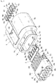
- Fig. 1 is a perspective view in which the electrical connector of the example that is assembled is seen from the front.
- Fig. 2 is a perspective view in which the assembled electrical connector is seen from the rear.
- Fig. 3 is a perspective view of a disassembled state seen from the rear.
- Fig. 4 is a vertical cross-sectional view in which the assembled electrical connector is vertically cut.
- Fig. 5 is a vertical cross-sectional view in which the assembled electrical connector is horizontally cut.
- the electrical connector includes a housing main body 1, a terminal holder 2 inserted into the housing main body 1 from the rear of the housing main body 1, a locking plate portion 3 connected to the front end of the terminal holder 2 and movable in the lateral direction that is orthogonal to the direction in which the terminal holder 2 is inserted, and an operating member 4 inserted from the front of the housing main body 1 and internally moving the locking plate portion 3 in the lateral direction.
- each of the housing main body 1, the terminal holder 2, the locking plate portion 3, and the operating member 4 is made of a synthetic resin material and manufactured by injection molding.
- the terminal holder 2 incorporating a connection terminal (described later) is inserted inward from the rear portion of the housing main body 1.
- the locking plate portion 3 is connected to the tip of the terminal holder 2 so as to be movable in the lateral direction, the locking plate portion 3 is inserted into the housing main body 1 together with the terminal holder 2, and the locking plate portion 3 is operated by the operating member 4 pushed in from the front portion of the housing main body 1.
- the locking plate portion 3 moves in the lateral direction that is orthogonal to the direction in which the locking plate portion 3 is inserted with respect to the terminal holder 2 and locks the rear end of the locking piece of the incorporated connection terminal.
- a total of 12 receiving-type connection terminals can be incorporated from the rear side and inter-connection terminal electrical connection is performed by connection on the front side to a counterpart electrical connector incorporating the same number of insertion-type connection terminals (so-called male terminals).
- the size of this small electrical connector that is assembled is, for example, 24 mm in width, 14 mm in height, and 24 mm in length.
- An appropriate size can be adopted in accordance with, for example, the size and number of the connection terminals.
- connection terminal incorporated in the housing main body 1 will be described first.
- the connection terminal is, for example, a receiving-type connection terminal with a total length of 15 mm formed by punching and bending a conductive metal plate (such as a brass plate) with a thickness of, for example, 0.15 mm.
- a square tube-shaped receiving connection portion Ta approximately 4.8 mm in length, 1.1 mm in width, and 1.6 mm in height is formed in the front portion of a connection terminal T. It should be noted that the dimensions do not limit the size of the connection terminal T.
- the locking piece Tc is formed to have a height of, for example, 0.4 mm with the side end portion cut out in a fin shape directed downward once and then folded back upward in a U shape.
- the locking piece Tc serves as a guide when the connection terminal T is inserted, serves as a stabilizer for stabilizing the posture of the connection terminal T after the insertion, and has a function of preventing the connection terminal T itself from escaping to the rear. Further, the upper end of the rear portion of the connection portion Ta is a pressed portion Td against which the case lance formed on the terminal holder 2 abuts from the rear.
- An electric wire W with an outer diameter of approximately 1 mm covered with a covering portion Wa is connected to the rear end portion of the connection terminal T.
- a core wire portion Wb at the tip of the electric wire W exposed from the covering portion Wa is crimp-connected to the connection terminal T by bending a U-shaped core wire crimping portion Te.
- a cylindrical sealing material Wc made of a synthetic rubber for waterproofing and inserted outside the covering portion Wa is crimp-fixed together with the covering portion Wa by bending a U-shaped covering crimping portion Tf.
- a middle tube 1a is provided in the middle portion of the housing main body 1.
- An outer tube 1b is disposed, with a gap, on the outside of the housing main body 1 so as to largely surround the middle tube 1a.
- the rear portion of the outer tube 1b is connected behind the middle tube 1a, and the middle tube 1a and the outer tube 1b are integrally molded.
- a holder holding portion 1c is open rearward so that the terminal holder 2 is inserted.
- the rear frame portion of the inserted terminal holder 2 is held by the holder holding portion 1c, and the front end of the middle tube 1a inside the outer tube 1b is a waterproof portion 1d slightly reduced in outer diameter.
- a tubular terminal holding portion 1e smaller in diameter than the middle tube 1a is formed further forward inside the middle tube 1a and with a slight gap from the middle tube 1a.
- the terminal holding portion 1e is supported by a plurality of ribs 1f from the inside of the middle tube 1a. It should be noted that a gap is provided between the ribs 1f so that the case lance of the terminal holder 2 (described later) enters.
- the terminal holding portion 1e is for holding the connection portion Ta of the connection terminal T therein, and the front wall of the terminal holding portion 1e is almost blocked with an opening portion (described later) and the operating member 4 left.
- Long groove-shaped coupling groove portions 1g for temporary insertion are formed as mechanisms for coupling the housing main body 1 and the terminal holder 2 to each other.
- the coupling groove portions 1g are formed in both side portions of the holder holding portion 1c.
- a coupling protrusion 2c for temporary insertion of the terminal holder 2 is fitted into the coupling groove portion 1g.
- two coupling groove portions 1h for main insertion in the upper portion of the holder holding portion 1c and two coupling groove portions 1h for main insertion in the lower portion of the holder holding portion 1c are formed as similar coupling mechanisms to receive coupling protrusions 2d for main insertion, which are provided on the terminal holder 2, during the main insertion of the terminal holder 2.
- a housing H on the other side is inserted between the middle tube 1a and the outer tube 1b.
- the periphery of the tip of the middle tube 1a is surrounded by a synthetic rubber made of, for example, silicon rubber as a waterproof member with respect to the housing H.
- This seal portion 1i is connected on both the inner and outer surfaces of the middle tube 1a via the small hole provided in the waterproof portion 1d and, on both the inner and outer surfaces, each cross section is wavy so that water infiltration is effectively blocked. It is preferable that the seal portion 1i is attached during the injection molding of the housing main body 1 and further cross-linked.
- connection portion accommodating chambers 1j (six rows on the left and six rows on the right in the upper and lower stages) with a square cross section are provided in the terminal holding portion 1e and individually store the connection portions Ta of the connection terminals T.
- Bottom plates 1k and 1k' for respectively supporting the bottom surfaces Tb of the connection terminals T are disposed back to back with a gap between the upper and lower connection portion accommodating chambers 1j.
- the total thickness of the bottom plates 1k and 1k' including the gap is, for example, 1.4 mm.
- a total of 10 sets of partition walls 11 and 11' (one upper wall and one lower wall constituting one set) extend with sufficient length in the longitudinal direction so that the connection terminals T adjacent to the right and left are partitioned.
- a gap is provided between the partition walls 11 and 11' .
- the space surrounded by the bottom plates 1k and 1k' and the partition walls 11 and 11' is the connection portion accommodating chamber 1j where the connection portion Ta is individually stored.
- the horizontal plate of the operating member 4 (described later) is inserted into the gap between the bottom plates 1k and 1k' and the vertical plate of the operating member 4 is inserted into the gap between the partition walls 11 and 11'.
- a total of 12 quadrangular opening portions 1n (six above and six below), into which the insertion ends of the insertion-type connection terminals on the other side are respectively inserted, are formed in the front wall 1m so as to correspond to the inserted individual connection terminals T.
- the front wall 1m is provided with a push-in port 1o for the operating member 4 inserted into the housing main body 1 so that the locking plate portion 3 is moved in the lateral direction.
- one horizontal groove 1p and a plurality of vertical grooves 1q are formed as the push-in port 1o, the horizontal groove 1p is provided between the upper and lower opening portions 1n, the vertical groove 1q is provided between the right and left opening portions 1n, the horizontal groove 1p communicates with the gap between the bottom plates 1k and 1k' of the terminal holding portion 1e, and the vertical groove 1q communicates with the gap of the partition walls 11 and 11' .
- Recess portions 1r into which the side plates on both sides of the operating member 4 are fitted are provided on both the right and left outer sides of the terminal holding portion 1e. Further, an elastic locking arm 1s for locking and maintaining the state of connection to the counterpart connector is formed in the upper middle portion of the outer tube 1b of the housing main body 1 and a locking claw 1t protrudes thereon.
- a frame portion 2a inserted into the holder holding portion 1c of the middle tube 1a is provided in the rear portion of the terminal holder 2.
- the frame portion 2a is provided with a total of 12 open holes 2b (six rows on the left and six rows on the right in the upper and lower stages) into which the connection terminals T are individually inserted.
- the open holes 2b have a circular cross section and a diameter of, for example, approximately 2.3 mm.
- each of the upper and lower portions of the frame portion 2a is provided with two coupling protrusions 2d for main insertion and the four upward and downward coupling protrusions 2d are fitted in the coupling groove portions 1h for main insertion of the holder holding portion 1c in the main insertion state.
- a stopper 2e for stopping the insertion of the terminal holder 2 with respect to the middle tube 1a during the main insertion at a predetermined position is provided upward and downward in the rear end portion of the terminal holder 2.
- coupling protrusions 2c and 2d may be provided on the holder holding portion 1c and the coupling groove portions 1g and 1h may be provided in the frame portion 2a.
- connection terminal T From the upper and lower portions of the front portions of the open holes 2b of the frame portion 2a, a total of 12 elastic case lances 2f (six each) protrude forward for each incorporated connection terminal T.
- connection terminals T the six connection portions Ta in the connection portion accommodating chambers 1j of the upper stage of the terminal holding portion 1e and the six connection portions Ta in the connection portion accommodating chambers 1j of the lower stage of the terminal holding portion 1e are incorporated in vertical symmetry, and thus the upper and lower case lances 2f are provided in vertical symmetry so as to correspond thereto.
- a hook portion 2g for abutting against and pressing the pressed portion Td of the connection portion Ta of the connection terminal T from the rear is formed in the vicinity of the tip of each case lance 2f and the upper and lower hook portions 2g are provided in vertical symmetry.
- a partition portion 2h partitioning the open holes 2b upward and downward and having a semicircular arc-shaped inner cross section continuous with the open hole 2b is provided between the upper and lower open holes 2b of the frame portion 2a.
- the thinnest part of the partition portion 2h has a thickness of 0.45 mm.
- a flat plate-shaped terminal placement plate 2i extends in front of the partition portion 2h.
- the terminal placement plate 2i has a thickness of, for example, 1.4 mm and allows the bottom surface Tb of each connection terminal T to be placed on both the upper and lower surfaces.
- the insertion groove 2j is formed in the front-rear direction in each of the upper and lower surfaces of the terminal placement plate 2i so that the locking piece Tc passes forward during the insertion of the connection terminal T.
- the insertion groove 2j has, for example, a width of 0.6 mm and a depth of 0.4 mm. It should be noted that the locking piece Tc is formed close to one width-direction side of the connection portion Ta and thus the upper and lower insertion grooves 2j are formed so as to be mutually misaligned in bilateral symmetry.
- the lopsided formation of the insertion grooves 2j is the same as in the case of the insertion grooves in both the upper and lower surfaces of the locking plate portion 3 illustrated in Fig. 8 (described later) .
- a wide slit-shaped connecting hole 2k is formed at the front end of the terminal placement plate 2i so that the insertion plate of the locking plate portion 3 (described later) is received so as to be movable in the lateral direction.
- the locking plate portion 3 includes a substrate portion 3a, an insertion plate 3b protruding rearward, and two operated ends 3c protruding forward.
- the substrate portion 3a is a substantially rectangular plate body with a thickness of 1.4 mm, which is the same as the gap of the bottom plates 1k and 1k' of the terminal holding portion 1e and the gap of the terminal placement plate 2i of the terminal holder 2.
- a total of six insertion grooves 3d are formed in the front-rear direction in each of the upper and lower surfaces of the substrate portion 3a.
- the 12 insertion grooves 3d communicate with the insertion grooves 2j in the terminal placement plate 2i at the position of insertion and connection of the locking plate portion 3 into and to the terminal holder 2 and have a width of 0.6 mm and a depth of 0.4 mm as in the case of the insertion groove 2j .
- a stepped notch provided in the width direction is formed in the front end side portion of each insertion groove 3d.
- the notch is a locking portion 3e for locking the locking piece Tc such that the connection terminal T does not escape to the rear.
- the one-dot chain line in Fig. 8 indicates a state where the locking piece Tc of the connection terminal T is inserted through the insertion groove 3d of the locking plate portion 3.
- the insertion plate 3b is fitted into the connecting hole 2k of the terminal holder 2, the insertion plate 3b is narrower than the connecting hole 2k and has a plate body shape having a thickness of approximately 0.6 mm.
- the operated end 3c is a strip having a thickness of approximately 0.6 mm and protruding forward from a front edge 3f of the substrate portion 3a.
- a receiving slope portion 3g is formed on one side of the tip of the operated end 3c.
- the receiving slope portion 3g is a wedge mechanism for redirection for laterally moving the locking plate portion 3 with respect to the housing main body 1 and the terminal holder 2 by means of the operating member 4.
- the operating member 4 is a member for laterally moving the internal locking plate portion 3 by push into the terminal holding portion 1e from the push-in port 1o of the front wall 1m of the housing main body 1.
- the operating member 4 includes a horizontal plate 4a with a thickness of 0.6 mm entering the gap of the bottom plates 1k and 1k', a plurality of vertical plates 4b with a thickness of 0.6 mm entering the gap of the partition walls 11 and 11', and a pair of side plates 4c on both sides.
- Two recess portions 4d receiving the operated end 3c of the locking plate portion 3 are formed in the insertion direction of the horizontal plate 4a, that is, at the front end.
- a push slope portion 4e as an operating portion is provided at two locations on one side of the entrance of the recess portion 4d in order to laterally move the locking plate portion 3 in cooperation with the receiving slope portion 3g of the operated end 3c.
- a push-in piece 4f is provided at the rear end of the horizontal plate 4a so that the operating member 4 is pushed in and the operating member 4 is pulled out as needed.
- the insertion plate 3b of the locking plate portion 3 is inserted into the connecting hole 2k at the tip of the terminal holder 2 and the locking plate portion 3 is connected to the terminal holder 2 so as to be movable in the lateral direction.
- the insertion plate 3b is brought close to one side with respect to the connecting hole 2k of the terminal placement plate 2i.
- the insertion groove 3d of the locking plate portion 3 communicates with the insertion groove 2j of the terminal placement plate 2i and the locking piece Tc of the connection terminal T is capable of passing through the insertion grooves 2j and 3d in sequence.
- the assembly in which the terminal holder 2 and the locking plate portion 3 are integrated in this manner is inserted from the rear of the housing main body 1 into the holder holding portion 1c of the middle tube 1a along a guide mechanism (not illustrated).
- a guide mechanism not illustrated
- the frame portion 2a of the terminal holder 2 is assembled, as a temporary insertion state, to the holder holding portion 1c as illustrated in Figs. 11 and 12 .
- the front end of the operated end 3c of the locking plate portion 3 is positioned near the gap between the bottom plates 1k and 1k' of the terminal holding portion 1e.
- the coupling protrusion 2c for temporary insertion of the terminal holder 2 pushes and expands the holder holding portion 1c of the housing main body 1 to the right and left, which leads to fitting and coupling to the coupling groove portion 1g for temporary insertion, and the front end of the coupling protrusion 2d for main insertion abuts against the rear end portion of the holder holding portion 1c.
- the case lance 2f provided on the terminal holder 2 is positioned between the ribs 1f between the terminal holding portion 1e and the waterproof portion 1d.
- connection terminals T are primarily inserted into the terminal holder 2 from the open hole 2b of the terminal holder 2 starting from the connection portion Ta of the connection terminal T.
- the individual connection portions Ta proceed on the terminal placement plate 2i while being guided by the partition walls 11 and 11' extending rearward from the terminal holding portion 1e. This entails a forward movement of the locking piece Tc of the connection portion Ta in the insertion groove 2j of the terminal placement plate 2i and, further, the insertion groove 3d of the locking plate portion 3.
- connection terminals T during the mounting into the terminal holder 2 are disposed in vertical symmetry in the housing main body 1 and the bottom surfaces Td are inserted back to back.
- the case lance 2f and the waterproof portion 1d of the middle tube 1a have a slight gap therebetween and the case lance 2f is deformable to the outside.
- the connection portion Ta passes through the hook portion 2g the case lance 2f returns to the original posture and the hook portion 2g abuts against the pressed portion Td of the connection portion Ta. Then, each connection terminal T stops at this primary insertion position as in the case of the connection terminal T in the lower stage.
- connection terminal T After the completion of the primary insertion of every connection terminal T, the terminal holder 2 is further pushed into the middle tube 1a together with the locking plate portion 3. As a result, the hook portion 2g of the case lance 2f pushes the pressed portion Td of the connection portion Ta forward as illustrated in Fig. 14 and the connection portion Ta of every connection terminal T is pushed in up to a predetermined position in the connection portion accommodating chamber 1j by the connection terminal T being moved forward from the primary insertion position to a secondary insertion position.
- the operated end 3c of the locking plate portion 3 is inserted into the gap between the bottom plates 1k and 1k' and, at the same time, the stopper 2e of the terminal holder 2 abuts against the rear end portion of the housing main body 1 and the terminal holder 2 and the locking plate portion 3 stop moving forward at this position.
- the coupling protrusion 2d for main insertion of the terminal holder 2 pushes and expands the holder holding portion 1c of the housing main body 1 up and down, which leads to fitting into the coupling groove portion 1h for main insertion, and the terminal holder 2 is coupled to the housing main body 1 in the main insertion state.
- the locking plate portion 3 and the terminal holder 2 incorporating the connection terminal T become immovable in the front-rear direction with respect to the housing main body 1 by the stopper 2e and the coupling protrusion 2d for main insertion of the terminal holder 2 sandwiching the rear end portion of the holder holding portion 1c.
- connection terminal T in this secondary insertion state the front position is determined with the front end of the connection portion Ta in the connection portion accommodating chamber 1j abutting against the inside of the front wall 1m.
- the hook portion 2g of the case lance 2f abuts against the pressed portion Td of the connection terminal T from the rear and the back slip of the connection terminal T is prevented.
- the locking piece Tc of the connection terminal T is stopped at the tip of the insertion groove 3d of the locking plate portion 3 via the insertion groove 2j of the terminal placement plate 2i as a stabilizer.
- the separate operating member 4 is pushed in from the push-in port 1o provided in the front wall 1m of the housing main body 1 and the horizontal plate 4a and the vertical plate 4b are pushed into the gaps of the bottom plates 1k and 1k' and the partition walls 11 and 11'.
- the side plates 4c on both sides of the operating member 4 are fitted into the recess portions 1r of the terminal holding portion 1e.
- connection portion Ta and the locking piece Tc of the connection terminal T are indicated by one-dot chain lines.
- the operating member 4 is strongly pushed in with respect to the locking plate portion 3 by means of the push-in piece 4f as indicated by the arrow A here, the operated end 3c of the locking plate portion 3 enters the recess portion 4d of the horizontal plate 4a of the operating member 4 as illustrated in Fig. 16 (b) .
- the pressing force of the operating member 4 causes the push slope portion 4e to apply a force proceeding in the lateral direction of the arrow B to the locking plate portion 3 by the inter-slope wedge action and with respect to the receiving slope portion 3g of the operated end 3c.
- the operated end 3c laterally moves in the gap of the bottom plates 1k and 1k' .
- the locking plate portion 3 moves laterally to the right when viewed from the front with respect to the terminal holder 2 and the housing main body 1. Further, at this position, a leftward movement of the locking plate portion 3 is regulated by the operating member 4, and thus the locking plate portion 3 does not unexpectedly return to the original position.
- the locking piece Tc positioned at the front end of the insertion groove 3d of the locking plate portion 3 is locked by the locking portion 3e provided on the side of the tip of the insertion groove 3d without the connection terminal T being moved.
- a rearward movement of the locking piece Tc is regulated.
- the lateral movement distance of the locking plate portion 3 is approximately 0.6 mm, which exceeds the width of the locking piece Tc. In this manner, the locking plate portion 3 does not return to the original position and the locking state of the locking piece Tc of the connection terminal T is maintained by the locking portion 3e insofar as the operating member 4 is inserted.
- Fig. 16 is a description of the operation on the upper surface of the locking plate portion 3, the same applies to the lower surface, and the rear portion of the locking piece Tc of the connection terminal T disposed on the lower surface side is locked by the locking portion 3e on the lower surface side.
- the locking plate portion 3 When the operating member 4 is sufficiently pushed in, the locking plate portion 3 is reliably moved in the lateral direction and the locking of the locking piece Tc is visually confirmed from the front.
- the operating member 4 is colored in a color different from, for example, the color of the housing main body 1 here, the mounting state of the operating member 4 can be visually recognized with greater ease. It should be noted that another method may be used as the mechanism of moving the locking plate portion 3 by means of the operating member 4.
- the pressed portion Td is locked by the case lance 2f and the locking piece Tc is locked by the locking portion 3e of the locking plate portion 3 as for the connection terminal T.
- connection terminal T at the main insertion position is positioned in the open hole 2b of the terminal holder 2, the cylindrical sealing material Wc attached to the connection terminal T is in close contact with the inner wall of the open hole 2b, and water infiltration from the rear into the terminal holder 2 and the middle tube 1a is prevented.
- the inside part of the seal portion 1i provided on the waterproof portion 1d provides sealing between the inside of the middle tube 1a and the outside of the terminal holder 2 and inward water infiltration from the gap between the middle tube 1a and the terminal holder 2 is prevented.
- the electrical connector configured as described above is fitted with the housing of the electrical connector on the other side during use, and the housings are locked by the locking claw 1t of the locking arm 1s.
- the insertion end of the connection terminal on the other side is inserted from the opening portion 1n of the front wall 1m and fitted into the connection portion Ta of the connection terminal T, and then the connection terminals are electrically connected.
- the push-in piece 4f of the operating member 4 at this time remains slightly protruding forward from the terminal holding portion 1e of the housing main body 1 and yet the push-in piece 4f is inserted into the recess of the housing of the counterpart connector when the connectors are fitted together.
- the electrical connector on the other side also has a waterproof structure
- the outer tube of the housing H on the other side is inserted between the outer tube 1b and the middle tube 1a of the housing main body 1
- the outside part of the seal portion 1i provided on the middle tube 1a provides sealing between the middle tube 1a and the outer tube of the housing H on the other side, and sealing is performed such that no inward water infiltration occurs from between the middle tube 1a and the outer tube of the housing H on the other side.
- the sealing structure by means of the seal portion 1i and the cylindrical sealing material Wc prevents water infiltration into the holder holding portion 1c and fitting with the waterproof housing H on the other side leads to functioning as a waterproof connector.
- connection terminals T are inserted into the upper and lower stages of the electrical connector with the bottom surfaces Tb facing each other, and thus the insertion grooves 3d of the locking pieces Tc respectively formed in the locking plate portion 3 and the terminal placement plate 2i of the terminal holder 2 are formed in both the upper and lower surfaces.
- the insertion groove may be formed in only one surface in the case of an electrical connector in which the connection terminal T is incorporated in one stage.
- the back slip regulation with respect to the locking piece Tc is released when the operating member 4 is pulled out by the push-in piece 4f and then the locking plate portion 3 is laterally moved to the left by a jig so that the connection terminal T is taken out of the housing main body 1 for repairing or the like.
- the case lance 2f may be unlocked with respect to the connection terminal T by dedicated jig insertion from the opening portion 1n of the front wall 1m and the connection terminal T may be pulled out rearward.
- the locking plate portion 3 is provided with the locking portion 3e locking the locking piece Tc of the connection terminal T.
- the locking piece Tc can be pushed into the insertion grooves in the bottom plates 1k and 1k' during the secondary insertion of the connection terminal T. Then, the locking of the locking piece Tc can also be performed not by the locking portion 3e but by the front edge 3f of the laterally moved locking plate portion 3 blocking the insertion grooves in the bottom plates 1k and 1k'.
- the insertion groove 2j is also provided in the terminal placement plate 2i of the terminal holder 2, the insertion groove 2j of the terminal holder 2 can be omitted insofar as the locking piece Tc of the connection terminal T can be directly guided to the insertion groove 3d of the locking plate portion 3 during the insertion of the connection terminal T.
- connection terminal T is a receiving-type connection terminal in the example, the invention is also applicable to an electrical connector in which the connection terminal is an insertion-type connection terminal. Further, the number of the connection terminals T can be changed and the number of the stages can be one or three or more.
Landscapes
- Engineering & Computer Science (AREA)
- Manufacturing & Machinery (AREA)
- Connector Housings Or Holding Contact Members (AREA)
Abstract
Description
- The present invention relates to an electrical connector that is used for automotive electric circuit connection or the like and can be reliably held in a housing even with a small connection terminal and a method for locking a connection terminal in the electrical connector.
- In the related art, a connection terminal incorporated in the housing of an electrical connector is prone to so-called back slip (pulling out to the rear from the housing) when a strong force is applied to the electric wire pulled out to the outside during harness processing or attachment to a car body. The back slip of the connection terminal impairs the function as an electrical connector, and thus the back slip is prevented by a locking mechanism provided in the housing and, in general, a flexible case lance provided in the housing performs locking.
- In recent years, however, a case lance alone is unlikely to be enough for a sufficient locking force as housings and case lances are required to be reduced in size along with connection terminals.
- Known in this regard is an electrical connector in which a case lance locks a connection terminal in a housing, a wide side holder is inserted from the side of the housing, and the connection terminal is locked in the housing as in
Patent Document 1. - In this electrical connector, the main body portion of the side holder is inserted in the housing from the side portion of the housing. In a case where the connection terminal is locked in the housing, the locking piece attached to the connection terminal is locked by the inserted side holder.
- Patent Document 1:
JP-A-2011-86504 - However, in the electrical connector of
Patent Document 1, a large hole portion for side holder insertion has to be formed in the side portion of the housing, it is difficult to waterproof the hole portion, and water infiltration into the housing is likely to occur. Accordingly, the electrical connector ofPatent Document 1 is not suitable as an electrical connector requiring waterproofness during inter-connection terminal connection. - In addition, the side holder has an end portion exposed on the outer surface of the side portion of the housing at all times, and thus the side holder may escape from the housing due to an unexpected contact with another member.
- An object of the invention for solving the above problems is to provide an electrical connector and a method for locking a connection terminal in the electrical connector in which the incorporated connection terminal is reliably locked and prevented from escaping to the rear by a locking plate portion incorporated in a housing being moved in the housing by an operating member inserted from the front of the housing.
- According to the electrical connector and the method for locking the connection terminal in the electrical connector of the invention, the connection terminal is locked by the movable locking plate portion provided in the housing main body being moved by the operating member of another member inserted from the front, and thus the connection terminal can be reliably held in the housing.
- In addition, it is possible to maintain waterproofness in the state of fitting with the electrical connector on the other side by forming the push-in port for pushing in the operating member in the front surface of the housing main body.
-
- [
Fig. 1] Fig. 1 is a perspective view in which an assembled electrical connector is seen from the front. - [
Fig. 2] Fig. 2 is a perspective view in which the assembled electrical connector is seen from the rear. - [
Fig. 3] Fig. 3 is a perspective view in which a disassembled electrical connector is seen from the rear. - [
Fig. 4] Fig. 4 is a vertical cross-sectional view in which the assembled electrical connector is vertically cut. - [
Fig. 5] Fig. 5 is a vertical cross-sectional view in which the assembled electrical connector is horizontally cut. - [
Fig. 6] Fig. 6 is a perspective view of a connection terminal. - [
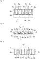
Fig. 7] Fig. 7 is a plan view of a locking plate portion. - [
Fig. 8] Fig. 8 is a front view of the locking plate portion. - [
Fig. 9] Fig. 9 is a plan view of an operating member. - [
Fig. 10] Fig. 10 is a perspective view of a state where the locking plate portion is connected to a terminal holder. - [
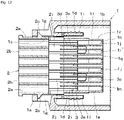
Fig. 11] Fig. 11 is a vertical cross-sectional view in which a housing is vertically cut with the terminal holder temporarily inserted. - [
Fig. 12] Fig. 12 is a vertical cross-sectional view in which a housing is horizontally cut with the terminal holder temporarily inserted. - [
Fig. 13] Fig. 13 is a vertical cross-sectional view of the process of primarily inserting the connection terminal in the temporary insertion state of the terminal holder. - [
Fig. 14] Fig. 14 is a vertical cross-sectional view of a state where the connection terminal is secondarily inserted. - [
Fig. 15] Fig. 15 is a vertical cross-sectional view of a state where the locking plate portion is inserted in the main insertion state of the terminal holder. - [
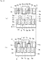
Fig. 16] Fig. 16 is an explanatory diagram of the process of pushing in the operating member and laterally moving the locking plate portion. - The invention will be described in detail with reference to the illustrated example.
-
Fig. 1 is a perspective view in which the electrical connector of the example that is assembled is seen from the front.Fig. 2 is a perspective view in which the assembled electrical connector is seen from the rear.Fig. 3 is a perspective view of a disassembled state seen from the rear.Fig. 4 is a vertical cross-sectional view in which the assembled electrical connector is vertically cut.Fig. 5 is a vertical cross-sectional view in which the assembled electrical connector is horizontally cut. - The electrical connector includes a housing
main body 1, aterminal holder 2 inserted into the housingmain body 1 from the rear of the housingmain body 1, alocking plate portion 3 connected to the front end of theterminal holder 2 and movable in the lateral direction that is orthogonal to the direction in which theterminal holder 2 is inserted, and anoperating member 4 inserted from the front of the housingmain body 1 and internally moving thelocking plate portion 3 in the lateral direction. It should be noted that each of the housingmain body 1, theterminal holder 2, thelocking plate portion 3, and theoperating member 4 is made of a synthetic resin material and manufactured by injection molding. - The
terminal holder 2 incorporating a connection terminal (described later) is inserted inward from the rear portion of the housingmain body 1. In addition, thelocking plate portion 3 is connected to the tip of theterminal holder 2 so as to be movable in the lateral direction, thelocking plate portion 3 is inserted into the housingmain body 1 together with theterminal holder 2, and thelocking plate portion 3 is operated by theoperating member 4 pushed in from the front portion of the housingmain body 1. As a result of this operation, thelocking plate portion 3 moves in the lateral direction that is orthogonal to the direction in which thelocking plate portion 3 is inserted with respect to theterminal holder 2 and locks the rear end of the locking piece of the incorporated connection terminal. - In the example of the electrical connector, for example, a total of 12 receiving-type connection terminals (so-called female terminals, six rows in the upper stage and six rows in the lower stage) can be incorporated from the rear side and inter-connection terminal electrical connection is performed by connection on the front side to a counterpart electrical connector incorporating the same number of insertion-type connection terminals (so-called male terminals).
- The size of this small electrical connector that is assembled is, for example, 24 mm in width, 14 mm in height, and 24 mm in length. An appropriate size can be adopted in accordance with, for example, the size and number of the connection terminals.
- The connection terminal incorporated in the housing
main body 1 will be described first. As illustrated in the perspective view ofFig. 6 , the connection terminal is, for example, a receiving-type connection terminal with a total length of 15 mm formed by punching and bending a conductive metal plate (such as a brass plate) with a thickness of, for example, 0.15 mm. A square tube-shaped receiving connection portion Ta approximately 4.8 mm in length, 1.1 mm in width, and 1.6 mm in height is formed in the front portion of a connection terminal T. It should be noted that the dimensions do not limit the size of the connection terminal T. - On one width-direction side of the rear end of a bottom surface Tb of the connection portion Ta, a locking piece Tc formed by a notch in the bottom surface Tb and locked by the
locking plate portion 3 protrudes downward and along the front-rear direction. The locking piece Tc is formed to have a height of, for example, 0.4 mm with the side end portion cut out in a fin shape directed downward once and then folded back upward in a U shape. - The locking piece Tc serves as a guide when the connection terminal T is inserted, serves as a stabilizer for stabilizing the posture of the connection terminal T after the insertion, and has a function of preventing the connection terminal T itself from escaping to the rear. Further, the upper end of the rear portion of the connection portion Ta is a pressed portion Td against which the case lance formed on the
terminal holder 2 abuts from the rear. - An electric wire W with an outer diameter of approximately 1 mm covered with a covering portion Wa is connected to the rear end portion of the connection terminal T. A core wire portion Wb at the tip of the electric wire W exposed from the covering portion Wa is crimp-connected to the connection terminal T by bending a U-shaped core wire crimping portion Te. Further, behind the core wire crimping portion Te, a cylindrical sealing material Wc made of a synthetic rubber for waterproofing and inserted outside the covering portion Wa is crimp-fixed together with the covering portion Wa by bending a U-shaped covering crimping portion Tf.
- A
middle tube 1a is provided in the middle portion of the housingmain body 1. Anouter tube 1b is disposed, with a gap, on the outside of the housingmain body 1 so as to largely surround themiddle tube 1a. The rear portion of theouter tube 1b is connected behind themiddle tube 1a, and themiddle tube 1a and theouter tube 1b are integrally molded. - In the rear portion of the
middle tube 1a, aholder holding portion 1c is open rearward so that theterminal holder 2 is inserted. The rear frame portion of the insertedterminal holder 2 is held by theholder holding portion 1c, and the front end of themiddle tube 1a inside theouter tube 1b is awaterproof portion 1d slightly reduced in outer diameter. - A tubular
terminal holding portion 1e smaller in diameter than themiddle tube 1a is formed further forward inside themiddle tube 1a and with a slight gap from themiddle tube 1a. Theterminal holding portion 1e is supported by a plurality ofribs 1f from the inside of themiddle tube 1a. It should be noted that a gap is provided between theribs 1f so that the case lance of the terminal holder 2 (described later) enters. Theterminal holding portion 1e is for holding the connection portion Ta of the connection terminal T therein, and the front wall of theterminal holding portion 1e is almost blocked with an opening portion (described later) and the operatingmember 4 left. - Long groove-shaped
coupling groove portions 1g for temporary insertion are formed as mechanisms for coupling the housingmain body 1 and theterminal holder 2 to each other. Thecoupling groove portions 1g are formed in both side portions of theholder holding portion 1c. When theterminal holder 2 is temporarily inserted, acoupling protrusion 2c for temporary insertion of theterminal holder 2 is fitted into thecoupling groove portion 1g. In addition, twocoupling groove portions 1h for main insertion in the upper portion of theholder holding portion 1c and twocoupling groove portions 1h for main insertion in the lower portion of theholder holding portion 1c are formed as similar coupling mechanisms to receivecoupling protrusions 2d for main insertion, which are provided on theterminal holder 2, during the main insertion of theterminal holder 2. - During the use of the electrical connector, a housing H on the other side is inserted between the
middle tube 1a and theouter tube 1b. For this reason, the periphery of the tip of themiddle tube 1a is surrounded by a synthetic rubber made of, for example, silicon rubber as a waterproof member with respect to the housing H. Thisseal portion 1i is connected on both the inner and outer surfaces of themiddle tube 1a via the small hole provided in thewaterproof portion 1d and, on both the inner and outer surfaces, each cross section is wavy so that water infiltration is effectively blocked. It is preferable that theseal portion 1i is attached during the injection molding of the housingmain body 1 and further cross-linked. - A total of 12 connection
portion accommodating chambers 1j (six rows on the left and six rows on the right in the upper and lower stages) with a square cross section are provided in theterminal holding portion 1e and individually store the connection portions Ta of the connection terminalsT. Bottom plates portion accommodating chambers 1j. The total thickness of thebottom plates - On both the upper and lower surfaces of the
bottom plates partition walls 11 and 11' (one upper wall and one lower wall constituting one set) extend with sufficient length in the longitudinal direction so that the connection terminals T adjacent to the right and left are partitioned. A gap is provided between thepartition walls 11 and 11' . Further, the space surrounded by thebottom plates partition walls 11 and 11' is the connectionportion accommodating chamber 1j where the connection portion Ta is individually stored. It should be noted that the horizontal plate of the operating member 4 (described later) is inserted into the gap between thebottom plates member 4 is inserted into the gap between thepartition walls 11 and 11'. - Although the front surface of the
terminal holding portion 1e is blocked by afront wall 1m, a total of 12quadrangular opening portions 1n (six above and six below), into which the insertion ends of the insertion-type connection terminals on the other side are respectively inserted, are formed in thefront wall 1m so as to correspond to the inserted individual connection terminals T. Further, thefront wall 1m is provided with a push-in port 1o for the operatingmember 4 inserted into the housingmain body 1 so that the lockingplate portion 3 is moved in the lateral direction. It should be noted that onehorizontal groove 1p and a plurality ofvertical grooves 1q are formed as the push-in port 1o, thehorizontal groove 1p is provided between the upper andlower opening portions 1n, thevertical groove 1q is provided between the right and leftopening portions 1n, thehorizontal groove 1p communicates with the gap between thebottom plates terminal holding portion 1e, and thevertical groove 1q communicates with the gap of thepartition walls 11 and 11' . -
Recess portions 1r into which the side plates on both sides of the operatingmember 4 are fitted are provided on both the right and left outer sides of theterminal holding portion 1e. Further, anelastic locking arm 1s for locking and maintaining the state of connection to the counterpart connector is formed in the upper middle portion of theouter tube 1b of the housingmain body 1 and a lockingclaw 1t protrudes thereon. - A
frame portion 2a inserted into theholder holding portion 1c of themiddle tube 1a is provided in the rear portion of theterminal holder 2. Theframe portion 2a is provided with a total of 12open holes 2b (six rows on the left and six rows on the right in the upper and lower stages) into which the connection terminals T are individually inserted. Theopen holes 2b have a circular cross section and a diameter of, for example, approximately 2.3 mm. - The coupling protrusions 2c for temporary insertion fitted in the
coupling groove portions 1g for temporary insertion of theholder holding portion 1c with theterminal holder 2 temporarily inserted protrude outward one by one on both the right and left side portions of theframe portion 2a. In addition, each of the upper and lower portions of theframe portion 2a is provided with twocoupling protrusions 2d for main insertion and the four upward anddownward coupling protrusions 2d are fitted in thecoupling groove portions 1h for main insertion of theholder holding portion 1c in the main insertion state. Further, astopper 2e for stopping the insertion of theterminal holder 2 with respect to themiddle tube 1a during the main insertion at a predetermined position is provided upward and downward in the rear end portion of theterminal holder 2. - It should be noted that the
coupling protrusions holder holding portion 1c and thecoupling groove portions frame portion 2a. - From the upper and lower portions of the front portions of the
open holes 2b of theframe portion 2a, a total of 12 elastic case lances 2f (six each) protrude forward for each incorporated connection terminal T. As for the connection terminals T, the six connection portions Ta in the connectionportion accommodating chambers 1j of the upper stage of theterminal holding portion 1e and the six connection portions Ta in the connectionportion accommodating chambers 1j of the lower stage of theterminal holding portion 1e are incorporated in vertical symmetry, and thus the upper andlower case lances 2f are provided in vertical symmetry so as to correspond thereto. In addition, ahook portion 2g for abutting against and pressing the pressed portion Td of the connection portion Ta of the connection terminal T from the rear is formed in the vicinity of the tip of eachcase lance 2f and the upper andlower hook portions 2g are provided in vertical symmetry. - A
partition portion 2h partitioning theopen holes 2b upward and downward and having a semicircular arc-shaped inner cross section continuous with theopen hole 2b is provided between the upper and loweropen holes 2b of theframe portion 2a. The thinnest part of thepartition portion 2h has a thickness of 0.45 mm. Further, a flat plate-shapedterminal placement plate 2i extends in front of thepartition portion 2h. Theterminal placement plate 2i has a thickness of, for example, 1.4 mm and allows the bottom surface Tb of each connection terminal T to be placed on both the upper and lower surfaces. - Six
insertion grooves 2j are formed in the front-rear direction in each of the upper and lower surfaces of theterminal placement plate 2i so that the locking piece Tc passes forward during the insertion of the connection terminal T. Theinsertion groove 2j has, for example, a width of 0.6 mm and a depth of 0.4 mm. It should be noted that the locking piece Tc is formed close to one width-direction side of the connection portion Ta and thus the upper andlower insertion grooves 2j are formed so as to be mutually misaligned in bilateral symmetry. - The lopsided formation of the
insertion grooves 2j is the same as in the case of the insertion grooves in both the upper and lower surfaces of the lockingplate portion 3 illustrated inFig. 8 (described later) . In addition, a wide slit-shaped connectinghole 2k is formed at the front end of theterminal placement plate 2i so that the insertion plate of the locking plate portion 3 (described later) is received so as to be movable in the lateral direction. - As illustrated in the plan view of
Fig. 7 and the front view ofFig. 8 , the lockingplate portion 3 includes asubstrate portion 3a, aninsertion plate 3b protruding rearward, and two operated ends 3c protruding forward. Thesubstrate portion 3a is a substantially rectangular plate body with a thickness of 1.4 mm, which is the same as the gap of thebottom plates terminal holding portion 1e and the gap of theterminal placement plate 2i of theterminal holder 2. - A total of six
insertion grooves 3d are formed in the front-rear direction in each of the upper and lower surfaces of thesubstrate portion 3a. The 12insertion grooves 3d communicate with theinsertion grooves 2j in theterminal placement plate 2i at the position of insertion and connection of the lockingplate portion 3 into and to theterminal holder 2 and have a width of 0.6 mm and a depth of 0.4 mm as in the case of theinsertion groove 2j . In addition, a stepped notch provided in the width direction is formed in the front end side portion of eachinsertion groove 3d. The notch is a lockingportion 3e for locking the locking piece Tc such that the connection terminal T does not escape to the rear. - It should be noted that the one-dot chain line in
Fig. 8 indicates a state where the locking piece Tc of the connection terminal T is inserted through theinsertion groove 3d of the lockingplate portion 3. - Although the
insertion plate 3b is fitted into the connectinghole 2k of theterminal holder 2, theinsertion plate 3b is narrower than the connectinghole 2k and has a plate body shape having a thickness of approximately 0.6 mm. In addition, the operatedend 3c is a strip having a thickness of approximately 0.6 mm and protruding forward from afront edge 3f of thesubstrate portion 3a. A receivingslope portion 3g is formed on one side of the tip of the operatedend 3c. The receivingslope portion 3g is a wedge mechanism for redirection for laterally moving the lockingplate portion 3 with respect to the housingmain body 1 and theterminal holder 2 by means of the operatingmember 4. - The operating
member 4 is a member for laterally moving the internallocking plate portion 3 by push into theterminal holding portion 1e from the push-in port 1o of thefront wall 1m of the housingmain body 1. As illustrated in the plan view ofFig. 9 , the operatingmember 4 includes ahorizontal plate 4a with a thickness of 0.6 mm entering the gap of thebottom plates vertical plates 4b with a thickness of 0.6 mm entering the gap of thepartition walls 11 and 11', and a pair ofside plates 4c on both sides. - Two
recess portions 4d receiving the operatedend 3c of the lockingplate portion 3 are formed in the insertion direction of thehorizontal plate 4a, that is, at the front end. At two locations on one side of the entrance of therecess portion 4d, apush slope portion 4e as an operating portion is provided in order to laterally move thelocking plate portion 3 in cooperation with the receivingslope portion 3g of the operatedend 3c. In addition, a push-inpiece 4f is provided at the rear end of thehorizontal plate 4a so that the operatingmember 4 is pushed in and the operatingmember 4 is pulled out as needed. - As illustrated in
Fig. 10 , during the assembly of the electrical connector, theinsertion plate 3b of the lockingplate portion 3 is inserted into the connectinghole 2k at the tip of theterminal holder 2 and thelocking plate portion 3 is connected to theterminal holder 2 so as to be movable in the lateral direction. In this case, theinsertion plate 3b is brought close to one side with respect to the connectinghole 2k of theterminal placement plate 2i. As a result, theinsertion groove 3d of the lockingplate portion 3 communicates with theinsertion groove 2j of theterminal placement plate 2i and the locking piece Tc of the connection terminal T is capable of passing through theinsertion grooves - The assembly in which the
terminal holder 2 and thelocking plate portion 3 are integrated in this manner is inserted from the rear of the housingmain body 1 into theholder holding portion 1c of themiddle tube 1a along a guide mechanism (not illustrated). As a result of this insertion, theframe portion 2a of theterminal holder 2 is assembled, as a temporary insertion state, to theholder holding portion 1c as illustrated inFigs. 11 and12 . - In this temporary insertion state, the front end of the operated
end 3c of the lockingplate portion 3 is positioned near the gap between thebottom plates terminal holding portion 1e. When theterminal holder 2 and thelocking plate portion 3 are temporarily inserted into the housingmain body 1, thecoupling protrusion 2c for temporary insertion of theterminal holder 2 pushes and expands theholder holding portion 1c of the housingmain body 1 to the right and left, which leads to fitting and coupling to thecoupling groove portion 1g for temporary insertion, and the front end of thecoupling protrusion 2d for main insertion abuts against the rear end portion of theholder holding portion 1c. In this temporary insertion state, thecase lance 2f provided on theterminal holder 2 is positioned between theribs 1f between theterminal holding portion 1e and thewaterproof portion 1d. - In this temporary insertion state, the rear end portion of the
holder holding portion 1c is sandwiched and coupled by thecoupling protrusion 2c for temporary insertion and thecoupling protrusion 2d for main insertion. Accordingly, theterminal holder 2 and thelocking plate portion 3 do not fall off from the housingmain body 1 and the temporary insertion state is maintained. In this manner, the state of assembly of the assemblies does not collapse even in the event of transport of the assembly in which theterminal holder 2 and thelocking plate portion 3 are temporarily inserted with respect to the housingmain body 1 to the insertion workplace for the connection terminal T for the next process. - Next, as illustrated in
Fig. 13 , the individual connection terminals T are primarily inserted into theterminal holder 2 from theopen hole 2b of theterminal holder 2 starting from the connection portion Ta of the connection terminal T. The individual connection portions Ta proceed on theterminal placement plate 2i while being guided by thepartition walls 11 and 11' extending rearward from theterminal holding portion 1e. This entails a forward movement of the locking piece Tc of the connection portion Ta in theinsertion groove 2j of theterminal placement plate 2i and, further, theinsertion groove 3d of the lockingplate portion 3. - It should be noted that the connection terminals T during the mounting into the
terminal holder 2 are disposed in vertical symmetry in the housingmain body 1 and the bottom surfaces Td are inserted back to back. - In the primary insertion process of the connection terminal T, the connection portions Ta at the tips of the connection terminals T in the upper stage and at the lower limit push up and down the
hook portion 2g of thecase lance 2f, pass through thehook portion 2g of thecase lance 2f, and enter the connectionportion accommodating chamber 1j as in the case of the connection terminal T in the upper stage. Thecase lance 2f and thewaterproof portion 1d of themiddle tube 1a have a slight gap therebetween and thecase lance 2f is deformable to the outside. When the connection portion Ta passes through thehook portion 2g, thecase lance 2f returns to the original posture and thehook portion 2g abuts against the pressed portion Td of the connection portion Ta. Then, each connection terminal T stops at this primary insertion position as in the case of the connection terminal T in the lower stage. - After the completion of the primary insertion of every connection terminal T, the
terminal holder 2 is further pushed into themiddle tube 1a together with the lockingplate portion 3. As a result, thehook portion 2g of thecase lance 2f pushes the pressed portion Td of the connection portion Ta forward as illustrated inFig. 14 and the connection portion Ta of every connection terminal T is pushed in up to a predetermined position in the connectionportion accommodating chamber 1j by the connection terminal T being moved forward from the primary insertion position to a secondary insertion position. - As a result, the operated
end 3c of the lockingplate portion 3 is inserted into the gap between thebottom plates stopper 2e of theterminal holder 2 abuts against the rear end portion of the housingmain body 1 and theterminal holder 2 and thelocking plate portion 3 stop moving forward at this position. In this main insertion process, thecoupling protrusion 2d for main insertion of theterminal holder 2 pushes and expands theholder holding portion 1c of the housingmain body 1 up and down, which leads to fitting into thecoupling groove portion 1h for main insertion, and theterminal holder 2 is coupled to the housingmain body 1 in the main insertion state. In this main insertion state, the lockingplate portion 3 and theterminal holder 2 incorporating the connection terminal T become immovable in the front-rear direction with respect to the housingmain body 1 by thestopper 2e and thecoupling protrusion 2d for main insertion of theterminal holder 2 sandwiching the rear end portion of theholder holding portion 1c. - In addition, as for the connection terminal T in this secondary insertion state, the front position is determined with the front end of the connection portion Ta in the connection
portion accommodating chamber 1j abutting against the inside of thefront wall 1m. In this stationary state of the connection terminal T, thehook portion 2g of thecase lance 2f abuts against the pressed portion Td of the connection terminal T from the rear and the back slip of the connection terminal T is prevented. At this time, the locking piece Tc of the connection terminal T is stopped at the tip of theinsertion groove 3d of the lockingplate portion 3 via theinsertion groove 2j of theterminal placement plate 2i as a stabilizer. - As illustrated in
Fig. 15 , in the main insertion state of theterminal holder 2 and thelocking plate portion 3, theseparate operating member 4 is pushed in from the push-in port 1o provided in thefront wall 1m of the housingmain body 1 and thehorizontal plate 4a and thevertical plate 4b are pushed into the gaps of thebottom plates partition walls 11 and 11'. In addition, theside plates 4c on both sides of the operatingmember 4 are fitted into therecess portions 1r of theterminal holding portion 1e. - As a result, the locking
plate portion 3 and the operatingmember 4 face each other in the housingmain body 1 as illustrated inFig. 16(a) . It should be noted that the connection portion Ta and the locking piece Tc of the connection terminal T are indicated by one-dot chain lines. When the operatingmember 4 is strongly pushed in with respect to thelocking plate portion 3 by means of the push-inpiece 4f as indicated by the arrow A here, the operatedend 3c of the lockingplate portion 3 enters therecess portion 4d of thehorizontal plate 4a of the operatingmember 4 as illustrated inFig. 16 (b) . The pressing force of the operatingmember 4 causes thepush slope portion 4e to apply a force proceeding in the lateral direction of the arrow B to thelocking plate portion 3 by the inter-slope wedge action and with respect to the receivingslope portion 3g of the operatedend 3c. - With the
insertion plate 3b of the lockingplate portion 3 positioned in the connectinghole 2k of theterminal placement plate 2i, the operatedend 3c laterally moves in the gap of thebottom plates plate portion 3 moves laterally to the right when viewed from the front with respect to theterminal holder 2 and the housingmain body 1. Further, at this position, a leftward movement of the lockingplate portion 3 is regulated by the operatingmember 4, and thus thelocking plate portion 3 does not unexpectedly return to the original position. - As a result of the lateral movement of the locking
plate portion 3, the locking piece Tc positioned at the front end of theinsertion groove 3d of the lockingplate portion 3 is locked by the lockingportion 3e provided on the side of the tip of theinsertion groove 3d without the connection terminal T being moved. As a result, a rearward movement of the locking piece Tc is regulated. The lateral movement distance of the lockingplate portion 3 is approximately 0.6 mm, which exceeds the width of the locking piece Tc. In this manner, the lockingplate portion 3 does not return to the original position and the locking state of the locking piece Tc of the connection terminal T is maintained by the lockingportion 3e insofar as the operatingmember 4 is inserted. - It should be noted that the description in
Fig. 16 is a description of the operation on the upper surface of the lockingplate portion 3, the same applies to the lower surface, and the rear portion of the locking piece Tc of the connection terminal T disposed on the lower surface side is locked by the lockingportion 3e on the lower surface side. - When the operating
member 4 is sufficiently pushed in, the lockingplate portion 3 is reliably moved in the lateral direction and the locking of the locking piece Tc is visually confirmed from the front. When the operatingmember 4 is colored in a color different from, for example, the color of the housingmain body 1 here, the mounting state of the operatingmember 4 can be visually recognized with greater ease. It should be noted that another method may be used as the mechanism of moving the lockingplate portion 3 by means of the operatingmember 4. - In this manner, the pressed portion Td is locked by the
case lance 2f and the locking piece Tc is locked by the lockingportion 3e of the lockingplate portion 3 as for the connection terminal T. By these two locking means, back slip attributable to, for example, the electric wire W being pulled out to the rear of the connection terminal T is reliably prevented. - In addition, as illustrated in
Fig. 15 , the rear end portion of the connection terminal T at the main insertion position is positioned in theopen hole 2b of theterminal holder 2, the cylindrical sealing material Wc attached to the connection terminal T is in close contact with the inner wall of theopen hole 2b, and water infiltration from the rear into theterminal holder 2 and themiddle tube 1a is prevented. Further, the inside part of theseal portion 1i provided on thewaterproof portion 1d provides sealing between the inside of themiddle tube 1a and the outside of theterminal holder 2 and inward water infiltration from the gap between themiddle tube 1a and theterminal holder 2 is prevented. - The electrical connector configured as described above is fitted with the housing of the electrical connector on the other side during use, and the housings are locked by the locking
claw 1t of thelocking arm 1s. The insertion end of the connection terminal on the other side is inserted from theopening portion 1n of thefront wall 1m and fitted into the connection portion Ta of the connection terminal T, and then the connection terminals are electrically connected. It should be noted that the push-inpiece 4f of the operatingmember 4 at this time remains slightly protruding forward from theterminal holding portion 1e of the housingmain body 1 and yet the push-inpiece 4f is inserted into the recess of the housing of the counterpart connector when the connectors are fitted together. - The electrical connector on the other side also has a waterproof structure, the outer tube of the housing H on the other side is inserted between the
outer tube 1b and themiddle tube 1a of the housingmain body 1, the outside part of theseal portion 1i provided on themiddle tube 1a provides sealing between themiddle tube 1a and the outer tube of the housing H on the other side, and sealing is performed such that no inward water infiltration occurs from between themiddle tube 1a and the outer tube of the housing H on the other side. In this manner, the sealing structure by means of theseal portion 1i and the cylindrical sealing material Wc prevents water infiltration into theholder holding portion 1c and fitting with the waterproof housing H on the other side leads to functioning as a waterproof connector. - In the example, the connection terminals T are inserted into the upper and lower stages of the electrical connector with the bottom surfaces Tb facing each other, and thus the
insertion grooves 3d of the locking pieces Tc respectively formed in thelocking plate portion 3 and theterminal placement plate 2i of theterminal holder 2 are formed in both the upper and lower surfaces. However, the insertion groove may be formed in only one surface in the case of an electrical connector in which the connection terminal T is incorporated in one stage. - In addition, the back slip regulation with respect to the locking piece Tc is released when the operating
member 4 is pulled out by the push-inpiece 4f and then the lockingplate portion 3 is laterally moved to the left by a jig so that the connection terminal T is taken out of the housingmain body 1 for repairing or the like. After the release, thecase lance 2f may be unlocked with respect to the connection terminal T by dedicated jig insertion from theopening portion 1n of thefront wall 1m and the connection terminal T may be pulled out rearward. - In the example described above, the locking
plate portion 3 is provided with the lockingportion 3e locking the locking piece Tc of the connection terminal T. However, when the lengths of thebottom plates bottom plates bottom plates bottom plates portion 3e but by thefront edge 3f of the laterally moved lockingplate portion 3 blocking the insertion grooves in thebottom plates - In addition, although the
insertion groove 2j is also provided in theterminal placement plate 2i of theterminal holder 2, theinsertion groove 2j of theterminal holder 2 can be omitted insofar as the locking piece Tc of the connection terminal T can be directly guided to theinsertion groove 3d of the lockingplate portion 3 during the insertion of the connection terminal T. - Although the connection terminal T is a receiving-type connection terminal in the example, the invention is also applicable to an electrical connector in which the connection terminal is an insertion-type connection terminal. Further, the number of the connection terminals T can be changed and the number of the stages can be one or three or more.
- It should be noted that the terms of up, down, right, left, front, and rear in the example are described with respect to the drawings and may differ from those in an actual electrical connector.
-
- 1
- Housing main body
- 1a
- Middle tube
- 1b
- Outer tube
- 1c
- Holder holding portion
- 1e
- Terminal holding portion
- 1j
- Connection portion accommodating chamber
- 1k, 1k'
- Bottom plate
- 11, 11'
- Partition wall
- 1m
- Front wall
- 1n
- Opening portion
- 1o
- Push-in port
- 2
- Terminal holder
- 2a
- Frame portion
- 2b
- Open hole
- 2f
- Case lance
- 2i
- Terminal placement plate
- 2j, 3d
- Insertion groove
- 3
- Locking plate portion
- 3a
- Substrate portion
- 3b
- Insertion plate
- 3c
- Operated end
- 3e
- Locking portion
- 3g
- Receiving slope portion
- 4
- Operating member
- 4a
- Horizontal plate
- 4b
- Vertical plate
- 4e
- Push slope portion
- T
- Connection terminal
- Ta
- Connection portion
- Tc
- Locking piece
- W
- Electric wire
Claims (11)
- An electrical connector comprising:a housing main body;a terminal holder inserted into the housing main body from a rear of the housing main body and incorporating a plurality of connection terminals having locking pieces;a locking plate portion connected to a front end of the terminal holder and movable in a lateral direction orthogonal to the direction in which the terminal holder is inserted; andan operating member moving the locking plate portion inserted in the housing main body together with the terminal holder in the lateral direction, whereinthe housing main body is provided with a holder holding portion holding the terminal holder in a rear portion and a terminal holding portion individually holding a connection portion of the connection terminal in a front portion,a plurality of open holes into which the connection terminals are respectively inserted are provided in a rear portion of the terminal holder,an insertion groove allowing the locking piece of the connection terminal to pass through a substrate portion is formed in the locking plate portion, an insertion plate connected to the terminal holder so as to be movable in the lateral direction is provided in a rear portion of the substrate portion, and an operated end for a movement in the lateral direction by the operating member is provided at a part of the substrate portion,the operating member is provided with an operating portion pushed in from a push-in port provided in the terminal holding portion of the housing main body and acting on the operated end of the locking plate portion, andas a result of the push, the operating portion of the operating member moves the locking plate portion in the lateral direction, locking is performed by the locking plate portion with respect to the locking piece of the connection terminal, and a back slip of the connection terminal is regulated.
- The electrical connector according to claim 1, wherein a stepped locking portion is provided in a front end side portion of the insertion groove of the locking plate portion and the locking portion regulates the back slip of the connection terminal by the locking plate portion moving in the lateral direction.
- The electrical connector according to claim 1, wherein an insertion groove communicating with the insertion groove of the locking plate portion is formed in a bottom plate of the terminal holding portion of the housing main body and the insertion groove of the bottom plate is blocked and the locking piece of the connection terminal is locked by the locking plate portion moving in the lateral direction.
- The electrical connector according to claim 1, wherein the connection terminals are incorporated in one upper stage and one lower stage with respect to the terminal holder and the insertion grooves of the locking plate portion are formed in both upper and lower surfaces of the locking plate portion.
- The electrical connector according to claim 1, wherein the terminal holder is provided with an insertion groove so as to communicate with the insertion groove of the locking plate portion.
- The electrical connector according to claim 1, wherein the locking plate portion is moved in the lateral direction by a wedge action with the operated end of the locking plate portion by the operating portion of the operating member abutting against the locking plate portion and being pushed in.
- The electrical connector according to claim 1, wherein the operating member in an insertion state thereof functions as confirmation means for confirming the movement of the locking plate portion in the lateral direction.
- The electrical connector according to claim 1, wherein the push-in port of the operating member is provided in a front surface of the terminal holding portion of the housing main body.
- The electrical connector according to claim 1, wherein the terminal holder allows an elastic case lance to protrude forward and the case lance locks a part of the connection terminal.
- The electrical connector according to claim 1, wherein the terminal holding portion of the housing main body has a waterproof structure preventing water infiltration.
- A method for locking a connection terminal in an electrical connector including a housing main body, a terminal holder inserted into the housing main body from a rear of the housing main body and incorporating a plurality of connection terminals having locking pieces, a locking plate portion connected to a front end of the terminal holder and movable in a lateral direction orthogonal to the direction in which the terminal holder is inserted, and an operating member moving the locking plate portion inserted in the housing main body together with the terminal holder in the lateral direction,
wherein, in the method for locking the electrical connector, a rear portion of the locking plate portion is connected to the terminal holder so as to be movable in the lateral direction, the connection terminal is inserted by the locking piece of the connection terminal moving forward in an insertion groove formed in the locking plate portion when the connection terminal is inserted, the locking plate portion is moved in the lateral direction by the operating member being pushed into the housing main body from a push-in port provided in the housing main body after the insertion of the connection terminal, and a rear portion of the locking piece of the connection terminal is locked and a rearward movement of the connection terminal is regulated as a result.
Applications Claiming Priority (2)
| Application Number | Priority Date | Filing Date | Title |
|---|---|---|---|
| JP2019105434A JP2020198277A (en) | 2019-06-05 | 2019-06-05 | Electrical connector and locking method of connection terminal in electrical connector |
| PCT/JP2020/021624 WO2020246428A1 (en) | 2019-06-05 | 2020-06-01 | Electrical connector and method for locking connection terminal in said electrical connector |
Publications (3)
| Publication Number | Publication Date |
|---|---|
| EP3982489A1 true EP3982489A1 (en) | 2022-04-13 |
| EP3982489A4 EP3982489A4 (en) | 2023-06-21 |
| EP3982489B1 EP3982489B1 (en) | 2025-09-17 |
Family
ID=73649316
Family Applications (1)
| Application Number | Title | Priority Date | Filing Date |
|---|---|---|---|
| EP20819494.4A Active EP3982489B1 (en) | 2019-06-05 | 2020-06-01 | Electrical connector and method for locking connection terminal in said electrical connector |
Country Status (5)
| Country | Link |
|---|---|
| US (1) | US11735856B2 (en) |
| EP (1) | EP3982489B1 (en) |
| JP (1) | JP2020198277A (en) |
| CN (1) | CN113748574A (en) |
| WO (1) | WO2020246428A1 (en) |
Families Citing this family (1)
| Publication number | Priority date | Publication date | Assignee | Title |
|---|---|---|---|---|
| JP7889294B2 (en) * | 2023-01-04 | 2026-07-14 | 住友電装株式会社 | Connector Assembly |
Family Cites Families (18)
| Publication number | Priority date | Publication date | Assignee | Title |
|---|---|---|---|---|
| JPH02174081A (en) | 1988-12-26 | 1990-07-05 | Nippon Ee M P Kk | Electric connector |
| ES2072951T3 (en) * | 1989-09-25 | 1995-08-01 | Whitaker Corp | ELECTRICAL CONNECTOR SET WITH MULTIPLE CONTACTS. |
| GB9421459D0 (en) * | 1994-10-25 | 1994-12-07 | Amp Italia | Sealable connector assembly having secondary lock |
| US5779501A (en) * | 1996-10-11 | 1998-07-14 | Ut Automotive Dearborn, Inc. | Connector |
| JP3983380B2 (en) * | 1998-06-08 | 2007-09-26 | 矢崎総業株式会社 | connector |
| JP2002343483A (en) * | 2001-05-11 | 2002-11-29 | Yazaki Corp | Connector with holder |
| DE20208632U1 (en) * | 2002-06-04 | 2003-10-16 | Robert Bosch Gmbh, 70469 Stuttgart | Secondary locking of a plug connection on two levels |
| JP2005327617A (en) * | 2004-05-14 | 2005-11-24 | Sumitomo Wiring Syst Ltd | Connector |
| FR2874751A1 (en) * | 2004-08-30 | 2006-03-03 | Fci Sa | ELECTRICAL CONNECTOR ADAPTED FOR MITIGATING VIBRATION, IN PARTICULAR FOR A MOTOR VEHICLE INJECTOR |
| JP5064933B2 (en) * | 2007-08-20 | 2012-10-31 | 古河電気工業株式会社 | Electrical connector |
| JP5330956B2 (en) | 2009-10-15 | 2013-10-30 | 古河電気工業株式会社 | Electrical connector |
| JP4922424B2 (en) | 2010-03-05 | 2012-04-25 | 日本航空電子工業株式会社 | Waterproof connector |
| JP5776667B2 (en) * | 2012-10-30 | 2015-09-09 | 住友電装株式会社 | connector |
| US9054454B2 (en) * | 2013-06-28 | 2015-06-09 | Delphi Technologies, Inc. | Electrical connector with a terminal stabilizer having an integrally formed arcuate resilient spring member |
| CN109155483B (en) | 2016-05-18 | 2020-09-22 | 日本端子株式会社 | Connector with a locking member |
| JP2018120666A (en) * | 2017-01-23 | 2018-08-02 | 住友電装株式会社 | Waterproof connector |
| JP6730975B2 (en) | 2017-11-27 | 2020-07-29 | 株式会社デルタプラス | Electric connector and method of locking connection terminals in the electric connector |
| JP6638106B1 (en) * | 2019-06-05 | 2020-01-29 | 株式会社デルタプラス | Electrical connector |
-
2019
- 2019-06-05 JP JP2019105434A patent/JP2020198277A/en active Pending
-
2020
- 2020-06-01 CN CN202080031830.4A patent/CN113748574A/en active Pending
- 2020-06-01 EP EP20819494.4A patent/EP3982489B1/en active Active
- 2020-06-01 WO PCT/JP2020/021624 patent/WO2020246428A1/en not_active Ceased
- 2020-06-01 US US17/611,178 patent/US11735856B2/en active Active
Also Published As
| Publication number | Publication date |
|---|---|
| EP3982489A4 (en) | 2023-06-21 |
| JP2020198277A (en) | 2020-12-10 |
| US20220216637A1 (en) | 2022-07-07 |
| WO2020246428A1 (en) | 2020-12-10 |
| EP3982489B1 (en) | 2025-09-17 |
| US11735856B2 (en) | 2023-08-22 |
| CN113748574A (en) | 2021-12-03 |
Similar Documents
| Publication | Publication Date | Title |
|---|---|---|
| US8747156B2 (en) | Terminal fitting | |
| US7097503B2 (en) | Connector and a method of disassembling it | |
| EP1158621B1 (en) | A connector housing | |
| US7204725B2 (en) | Connector and method of assembling it | |
| US10367290B2 (en) | Connector device and male connector | |
| US10340621B2 (en) | Connector with moving plate having partition between terminals to prevent short-circuit | |
| JP3317390B2 (en) | connector | |
| US11942737B2 (en) | Joint connector | |
| CN101383459B (en) | Cable connector and connector assembly | |
| US7086910B2 (en) | Connector | |
| US10079445B2 (en) | Electrical connector for a twisted pair cable | |
| US11177605B2 (en) | Connector, jig and method for manufacturing connector | |
| EP3982489B1 (en) | Electrical connector and method for locking connection terminal in said electrical connector | |
| US20050136714A1 (en) | Connector | |
| US9281600B2 (en) | Connector with retainer having reinforced escaping portion | |
| US7207848B2 (en) | Connector assembly with slider assisted mating and terminal lock | |
| JP6730975B2 (en) | Electric connector and method of locking connection terminals in the electric connector | |
| US7175483B2 (en) | Connector | |
| US11095064B2 (en) | Connector structure | |
| CN111213287B (en) | Connector, jig, and method for assembling terminal to connector | |
| US20060084326A1 (en) | Connector | |
| US6669508B2 (en) | Connector | |
| JP2003077579A (en) | connector | |
| US20250286302A1 (en) | Connector and connector manufacturing method | |
| JPH0922750A (en) | connector |
Legal Events
| Date | Code | Title | Description |
|---|---|---|---|
| STAA | Information on the status of an ep patent application or granted ep patent |
Free format text: STATUS: THE INTERNATIONAL PUBLICATION HAS BEEN MADE |
|
| PUAI | Public reference made under article 153(3) epc to a published international application that has entered the european phase |
Free format text: ORIGINAL CODE: 0009012 |
|
| STAA | Information on the status of an ep patent application or granted ep patent |
Free format text: STATUS: REQUEST FOR EXAMINATION WAS MADE |
|
| 17P | Request for examination filed |
Effective date: 20210614 |
|
| AK | Designated contracting states |
Kind code of ref document: A1 Designated state(s): AL AT BE BG CH CY CZ DE DK EE ES FI FR GB GR HR HU IE IS IT LI LT LU LV MC MK MT NL NO PL PT RO RS SE SI SK SM TR |
|
| DAV | Request for validation of the european patent (deleted) | ||
| DAX | Request for extension of the european patent (deleted) | ||
| REG | Reference to a national code |
Free format text: PREVIOUS MAIN CLASS: H01R0013420000 Ref country code: DE Ref legal event code: R079 Ref document number: 602020059063 Country of ref document: DE Ipc: H01R0013436000 |
|
| A4 | Supplementary search report drawn up and despatched |
Effective date: 20230523 |
|
| RIC1 | Information provided on ipc code assigned before grant |
Ipc: H01R 13/506 20060101ALI20230516BHEP Ipc: H01R 13/52 20060101ALI20230516BHEP Ipc: H01R 13/436 20060101AFI20230516BHEP |
|
| GRAP | Despatch of communication of intention to grant a patent |
Free format text: ORIGINAL CODE: EPIDOSNIGR1 |
|
| STAA | Information on the status of an ep patent application or granted ep patent |
Free format text: STATUS: GRANT OF PATENT IS INTENDED |
|
| INTG | Intention to grant announced |
Effective date: 20250611 |
|
| GRAS | Grant fee paid |
Free format text: ORIGINAL CODE: EPIDOSNIGR3 |
|
| GRAA | (expected) grant |
Free format text: ORIGINAL CODE: 0009210 |
|
| STAA | Information on the status of an ep patent application or granted ep patent |
Free format text: STATUS: THE PATENT HAS BEEN GRANTED |
|
| AK | Designated contracting states |
Kind code of ref document: B1 Designated state(s): AL AT BE BG CH CY CZ DE DK EE ES FI FR GB GR HR HU IE IS IT LI LT LU LV MC MK MT NL NO PL PT RO RS SE SI SK SM TR |
|
| REG | Reference to a national code |
Ref country code: GB Ref legal event code: FG4D |
|
| REG | Reference to a national code |
Ref country code: CH Ref legal event code: EP |
|
| REG | Reference to a national code |
Ref country code: DE Ref legal event code: R096 Ref document number: 602020059063 Country of ref document: DE |
|
| REG | Reference to a national code |
Ref country code: IE Ref legal event code: FG4D |
|
| PG25 | Lapsed in a contracting state [announced via postgrant information from national office to epo] |
Ref country code: NO Free format text: LAPSE BECAUSE OF FAILURE TO SUBMIT A TRANSLATION OF THE DESCRIPTION OR TO PAY THE FEE WITHIN THE PRESCRIBED TIME-LIMIT Effective date: 20251217 |
|
| REG | Reference to a national code |
Ref country code: LT Ref legal event code: MG9D |
|
| PG25 | Lapsed in a contracting state [announced via postgrant information from national office to epo] |
Ref country code: FI Free format text: LAPSE BECAUSE OF FAILURE TO SUBMIT A TRANSLATION OF THE DESCRIPTION OR TO PAY THE FEE WITHIN THE PRESCRIBED TIME-LIMIT Effective date: 20250917 |
|
| PG25 | Lapsed in a contracting state [announced via postgrant information from national office to epo] |
Ref country code: HR Free format text: LAPSE BECAUSE OF FAILURE TO SUBMIT A TRANSLATION OF THE DESCRIPTION OR TO PAY THE FEE WITHIN THE PRESCRIBED TIME-LIMIT Effective date: 20250917 |
|
| PG25 | Lapsed in a contracting state [announced via postgrant information from national office to epo] |
Ref country code: GR Free format text: LAPSE BECAUSE OF FAILURE TO SUBMIT A TRANSLATION OF THE DESCRIPTION OR TO PAY THE FEE WITHIN THE PRESCRIBED TIME-LIMIT Effective date: 20251218 |
|
| PG25 | Lapsed in a contracting state [announced via postgrant information from national office to epo] |
Ref country code: SE Free format text: LAPSE BECAUSE OF FAILURE TO SUBMIT A TRANSLATION OF THE DESCRIPTION OR TO PAY THE FEE WITHIN THE PRESCRIBED TIME-LIMIT Effective date: 20250917 |
|
| REG | Reference to a national code |
Ref country code: NL Ref legal event code: MP Effective date: 20250917 |
|
| PG25 | Lapsed in a contracting state [announced via postgrant information from national office to epo] |
Ref country code: LV Free format text: LAPSE BECAUSE OF FAILURE TO SUBMIT A TRANSLATION OF THE DESCRIPTION OR TO PAY THE FEE WITHIN THE PRESCRIBED TIME-LIMIT Effective date: 20250917 |
|
| PG25 | Lapsed in a contracting state [announced via postgrant information from national office to epo] |
Ref country code: BG Free format text: LAPSE BECAUSE OF FAILURE TO SUBMIT A TRANSLATION OF THE DESCRIPTION OR TO PAY THE FEE WITHIN THE PRESCRIBED TIME-LIMIT Effective date: 20250917 |
|
| PG25 | Lapsed in a contracting state [announced via postgrant information from national office to epo] |
Ref country code: RS Free format text: LAPSE BECAUSE OF FAILURE TO SUBMIT A TRANSLATION OF THE DESCRIPTION OR TO PAY THE FEE WITHIN THE PRESCRIBED TIME-LIMIT Effective date: 20251217 |
|
| PG25 | Lapsed in a contracting state [announced via postgrant information from national office to epo] |
Ref country code: NL Free format text: LAPSE BECAUSE OF FAILURE TO SUBMIT A TRANSLATION OF THE DESCRIPTION OR TO PAY THE FEE WITHIN THE PRESCRIBED TIME-LIMIT Effective date: 20250917 |
|
| REG | Reference to a national code |
Ref country code: AT Ref legal event code: MK05 Ref document number: 1839189 Country of ref document: AT Kind code of ref document: T Effective date: 20250917 |
|
| PG25 | Lapsed in a contracting state [announced via postgrant information from national office to epo] |
Ref country code: SM Free format text: LAPSE BECAUSE OF FAILURE TO SUBMIT A TRANSLATION OF THE DESCRIPTION OR TO PAY THE FEE WITHIN THE PRESCRIBED TIME-LIMIT Effective date: 20250917 |
|
| PG25 | Lapsed in a contracting state [announced via postgrant information from national office to epo] |
Ref country code: ES Free format text: LAPSE BECAUSE OF FAILURE TO SUBMIT A TRANSLATION OF THE DESCRIPTION OR TO PAY THE FEE WITHIN THE PRESCRIBED TIME-LIMIT Effective date: 20250917 |
|
| PG25 | Lapsed in a contracting state [announced via postgrant information from national office to epo] |
Ref country code: AT Free format text: LAPSE BECAUSE OF FAILURE TO SUBMIT A TRANSLATION OF THE DESCRIPTION OR TO PAY THE FEE WITHIN THE PRESCRIBED TIME-LIMIT Effective date: 20250917 |
|
| PG25 | Lapsed in a contracting state [announced via postgrant information from national office to epo] |
Ref country code: IT Free format text: LAPSE BECAUSE OF FAILURE TO SUBMIT A TRANSLATION OF THE DESCRIPTION OR TO PAY THE FEE WITHIN THE PRESCRIBED TIME-LIMIT Effective date: 20250917 |
|
| PG25 | Lapsed in a contracting state [announced via postgrant information from national office to epo] |
Ref country code: IS Free format text: LAPSE BECAUSE OF FAILURE TO SUBMIT A TRANSLATION OF THE DESCRIPTION OR TO PAY THE FEE WITHIN THE PRESCRIBED TIME-LIMIT Effective date: 20260117 |
|
| PG25 | Lapsed in a contracting state [announced via postgrant information from national office to epo] |
Ref country code: CZ Free format text: LAPSE BECAUSE OF FAILURE TO SUBMIT A TRANSLATION OF THE DESCRIPTION OR TO PAY THE FEE WITHIN THE PRESCRIBED TIME-LIMIT Effective date: 20250917 Ref country code: PT Free format text: LAPSE BECAUSE OF FAILURE TO SUBMIT A TRANSLATION OF THE DESCRIPTION OR TO PAY THE FEE WITHIN THE PRESCRIBED TIME-LIMIT Effective date: 20260119 |
|
| PG25 | Lapsed in a contracting state [announced via postgrant information from national office to epo] |
Ref country code: PL Free format text: LAPSE BECAUSE OF FAILURE TO SUBMIT A TRANSLATION OF THE DESCRIPTION OR TO PAY THE FEE WITHIN THE PRESCRIBED TIME-LIMIT Effective date: 20250917 |
|
| PG25 | Lapsed in a contracting state [announced via postgrant information from national office to epo] |
Ref country code: SK Free format text: LAPSE BECAUSE OF FAILURE TO SUBMIT A TRANSLATION OF THE DESCRIPTION OR TO PAY THE FEE WITHIN THE PRESCRIBED TIME-LIMIT Effective date: 20250917 Ref country code: EE Free format text: LAPSE BECAUSE OF FAILURE TO SUBMIT A TRANSLATION OF THE DESCRIPTION OR TO PAY THE FEE WITHIN THE PRESCRIBED TIME-LIMIT Effective date: 20250917 |
|
| REG | Reference to a national code |
Ref country code: DE Ref legal event code: R097 Ref document number: 602020059063 Country of ref document: DE |
|
| PG25 | Lapsed in a contracting state [announced via postgrant information from national office to epo] |
Ref country code: LT Free format text: LAPSE BECAUSE OF FAILURE TO SUBMIT A TRANSLATION OF THE DESCRIPTION OR TO PAY THE FEE WITHIN THE PRESCRIBED TIME-LIMIT Effective date: 20250917 |
|
| PG25 | Lapsed in a contracting state [announced via postgrant information from national office to epo] |
Ref country code: DK Free format text: LAPSE BECAUSE OF FAILURE TO SUBMIT A TRANSLATION OF THE DESCRIPTION OR TO PAY THE FEE WITHIN THE PRESCRIBED TIME-LIMIT Effective date: 20250917 |
|
| PGFP | Annual fee paid to national office [announced via postgrant information from national office to epo] |
Ref country code: DE Payment date: 20260622 Year of fee payment: 7 |
|
| PGFP | Annual fee paid to national office [announced via postgrant information from national office to epo] |
Ref country code: FR Payment date: 20260626 Year of fee payment: 7 |
|
| PLBE | No opposition filed within time limit |
Free format text: ORIGINAL CODE: 0009261 |
|
| STAA | Information on the status of an ep patent application or granted ep patent |
Free format text: STATUS: NO OPPOSITION FILED WITHIN TIME LIMIT |
|
| REG | Reference to a national code |
Ref country code: CH Ref legal event code: L10 Free format text: ST27 STATUS EVENT CODE: U-0-0-L10-L00 (AS PROVIDED BY THE NATIONAL OFFICE) Effective date: 20260729 |