EP3982459A1 - Container and method for charging secondary battery - Google Patents
Container and method for charging secondary battery Download PDFInfo
- Publication number
- EP3982459A1 EP3982459A1 EP20823122.5A EP20823122A EP3982459A1 EP 3982459 A1 EP3982459 A1 EP 3982459A1 EP 20823122 A EP20823122 A EP 20823122A EP 3982459 A1 EP3982459 A1 EP 3982459A1
- Authority
- EP
- European Patent Office
- Prior art keywords
- secondary battery
- electrode
- cavity
- conductive line
- carrier sheet
- Prior art date
- Legal status (The legal status is an assumption and is not a legal conclusion. Google has not performed a legal analysis and makes no representation as to the accuracy of the status listed.)
- Pending
Links
Images




Classifications
-
- H—ELECTRICITY
- H02—GENERATION; CONVERSION OR DISTRIBUTION OF ELECTRIC POWER
- H02J—ELECTRIC POWER NETWORKS; CIRCUIT ARRANGEMENTS OR SYSTEMS FOR SUPPLYING OR DISTRIBUTING ELECTRIC POWER; SYSTEMS FOR STORING ELECTRIC ENERGY
- H02J7/00—Circuit arrangements for charging or discharging batteries or for supplying loads from batteries
- H02J7/70—Circuit arrangements for charging or discharging batteries or for supplying loads from batteries characterised by the mechanical construction
- H02J7/751—Circuit arrangements for charging or discharging batteries or for supplying loads from batteries characterised by the mechanical construction concerning the insertion or the connection of the batteries
-
- H—ELECTRICITY
- H01—ELECTRIC ELEMENTS
- H01M—PROCESSES OR MEANS, e.g. BATTERIES, FOR THE DIRECT CONVERSION OF CHEMICAL ENERGY INTO ELECTRICAL ENERGY
- H01M10/00—Secondary cells; Manufacture thereof
- H01M10/42—Methods or arrangements for servicing or maintenance of secondary cells or secondary half-cells
- H01M10/44—Methods for charging or discharging
-
- H—ELECTRICITY
- H01—ELECTRIC ELEMENTS
- H01M—PROCESSES OR MEANS, e.g. BATTERIES, FOR THE DIRECT CONVERSION OF CHEMICAL ENERGY INTO ELECTRICAL ENERGY
- H01M10/00—Secondary cells; Manufacture thereof
- H01M10/42—Methods or arrangements for servicing or maintenance of secondary cells or secondary half-cells
- H01M10/46—Accumulators structurally combined with charging apparatus
-
- H—ELECTRICITY
- H01—ELECTRIC ELEMENTS
- H01M—PROCESSES OR MEANS, e.g. BATTERIES, FOR THE DIRECT CONVERSION OF CHEMICAL ENERGY INTO ELECTRICAL ENERGY
- H01M50/00—Constructional details or processes of manufacture of the non-active parts of electrochemical cells other than fuel cells, e.g. hybrid cells
- H01M50/20—Mountings; Secondary casings or frames; Racks, modules or packs; Suspension devices; Shock absorbers; Transport or carrying devices; Holders
- H01M50/204—Racks, modules or packs for multiple batteries or multiple cells
- H01M50/207—Racks, modules or packs for multiple batteries or multiple cells characterised by their shape
- H01M50/209—Racks, modules or packs for multiple batteries or multiple cells characterised by their shape adapted for prismatic or rectangular cells
-
- H—ELECTRICITY
- H02—GENERATION; CONVERSION OR DISTRIBUTION OF ELECTRIC POWER
- H02J—ELECTRIC POWER NETWORKS; CIRCUIT ARRANGEMENTS OR SYSTEMS FOR SUPPLYING OR DISTRIBUTING ELECTRIC POWER; SYSTEMS FOR STORING ELECTRIC ENERGY
- H02J7/00—Circuit arrangements for charging or discharging batteries or for supplying loads from batteries
- H02J7/50—Circuit arrangements for charging or discharging batteries or for supplying loads from batteries acting upon multiple batteries simultaneously or sequentially
-
- H—ELECTRICITY
- H01—ELECTRIC ELEMENTS
- H01M—PROCESSES OR MEANS, e.g. BATTERIES, FOR THE DIRECT CONVERSION OF CHEMICAL ENERGY INTO ELECTRICAL ENERGY
- H01M50/00—Constructional details or processes of manufacture of the non-active parts of electrochemical cells other than fuel cells, e.g. hybrid cells
- H01M50/20—Mountings; Secondary casings or frames; Racks, modules or packs; Suspension devices; Shock absorbers; Transport or carrying devices; Holders
- H01M50/233—Mountings; Secondary casings or frames; Racks, modules or packs; Suspension devices; Shock absorbers; Transport or carrying devices; Holders characterised by physical properties of casings or racks, e.g. dimensions
- H01M50/238—Flexibility or foldability
-
- Y—GENERAL TAGGING OF NEW TECHNOLOGICAL DEVELOPMENTS; GENERAL TAGGING OF CROSS-SECTIONAL TECHNOLOGIES SPANNING OVER SEVERAL SECTIONS OF THE IPC; TECHNICAL SUBJECTS COVERED BY FORMER USPC CROSS-REFERENCE ART COLLECTIONS [XRACs] AND DIGESTS
- Y02—TECHNOLOGIES OR APPLICATIONS FOR MITIGATION OR ADAPTATION AGAINST CLIMATE CHANGE
- Y02E—REDUCTION OF GREENHOUSE GAS [GHG] EMISSIONS, RELATED TO ENERGY GENERATION, TRANSMISSION OR DISTRIBUTION
- Y02E60/00—Enabling technologies; Technologies with a potential or indirect contribution to GHG emissions mitigation
- Y02E60/10—Energy storage using batteries
Definitions
- the present invention relates to a package that accommodates a secondary battery or an electronic component including the secondary battery, and a method of charging the secondary battery accommodated in the package.
- Patent Document 1 discloses a series of electronic components including a long carrier tape in which a plurality of cavities is formed along a longitudinal direction, an electronic component accommodated in each of the cavities, and a cover film bonded to the carrier tape so as to cover the cavities.
- a usage mode of the series of electronic components for example, a usage mode is conceivable in which the secondary battery charged in advance is transported to a manufacturing factory of an electronic device in a state of being accommodated in a cavity, and in the factory as a transport destination, the secondary battery is taken out from the carrier tape by having the cover film peeled off and is used to manufacture the electronic device.
- Patent Document 1 Japanese Patent Application Laid-Open No. 2004-268916 A
- the capacity of the secondary battery decreases due to self-discharge if the time that has passed is long before the secondary battery is actually used. In that case, the secondary batteries need to be taken out one by one from the carrier tape and to be charged again, which takes time and effort.
- the present invention has been made to solve the above problem, and an object of the present invention is to provide a package that can charge a plurality of secondary batteries or an electronic component including the secondary battery that are accommodated in a carrier sheet without having the secondary batteries or the electronic component taken out from the carrier sheet, and a method of charging the secondary battery accommodated in the package.
- the package of the present invention includes:
- the cavities may be formed in plural numbers also in a lateral direction orthogonal to the longitudinal direction of the carrier sheet.
- the first electrode may be formed on one end side of the cavity, and the second electrode may be formed on the other end side of the cavity.
- first electrode may be formed on a side of a first end of the cavity in the longitudinal direction and on a side of a second end of the cavity in the lateral direction orthogonal to the longitudinal direction
- second electrode may be formed on a side of a third end of the cavity facing the first end in the longitudinal direction and on a side of a fourth end of the cavity facing the second end in the lateral direction.
- the cavity may be provided with a movement suppression mechanism configured to suppress movement of the secondary battery or the electronic component.
- the package may further include a cover sheet that is bonded to the carrier sheet in a manner of covering an opening of the cavity in which the secondary battery or the electronic component is accommodated, and the cover sheet may include a protrusion that abuts to the secondary battery or the electronic component in a state where the cover sheet is bonded to the carrier sheet.
- the cavity and the secondary battery may have a difference in dimensions which may be smaller than a difference in dimensions between the first electrode and the second electrode.
- a method of charging a secondary battery includes the steps of:
- the secondary battery can be charged by applying the DC voltage between the first conductive line and the second conductive line in a state where the secondary battery having the pair of external electrodes or the electronic component including the secondary battery is accommodated in the cavity of the carrier sheet.
- the secondary battery can be charged before being taken out from the carrier sheet.
- the secondary battery or the electronic component including the secondary battery can be accommodated in the carrier sheet without charging the secondary battery.
- the secondary battery can be charged by applying the DC voltage between the first conductive line and the second conductive line in the state where the secondary battery having the pair of external electrodes or the electronic component including the secondary battery is accommodated in the cavity of the carrier sheet.
- FIG. 1 is a plan view showing a configuration of a package 100 in a first embodiment of the present invention.
- FIG. 2 is a sectional view taken along a line II-II of the package 100 shown in FIG. 1 .
- the package 100 in the first embodiment includes a cavity 11 for accommodating the secondary battery 1 having a pair of external electrodes or an electronic component including the secondary battery 1, a long carrier sheet 10 in which a plurality of cavities 11 are formed along a longitudinal direction L, a first electrode 21 and a second electrode 22 for charging the secondary battery 1, a first conductive line 31 electrically connected to the plurality of first electrodes 21, and a second conductive line 32 electrically connected to the plurality of second electrodes 22.
- the package 100 in the present embodiment further includes a cover sheet 40.
- the carrier sheet 10 is made of material having flexibility, such as paper or synthetic resin.
- the dimension of the carrier sheet 10 in a lateral direction W is, for example, 10 mm, and the dimension in a thickness direction T is, for example, 3 mm. These dimensions are appropriately changed depending on the size of the secondary battery 1 to be accommodated.
- the dimension of the carrier sheet 10 in the longitudinal direction L can be an optional dimension.
- the cavity 11 formed in the carrier sheet 10 is a space for accommodating the secondary battery 1 or the electronic component including the secondary battery 1.
- the plurality of cavities 11 are formed, for example, at equal intervals along the longitudinal direction L of the carrier sheet 10.
- the cavity 11 is formed such that the longitudinal direction of the cavity 11 having a rectangular shape in plan view coincides with the longitudinal direction L of the carrier sheet 10.
- the cavity 11 has a size that can fully accommodate the secondary battery 1 in plan view.
- the dimension of the cavity 11 in the lateral direction is shorter than the dimension in the longitudinal direction of the secondary battery 1 to be accommodated.
- the dimensions of the cavity 11 in the longitudinal direction L, the lateral direction W, and the thickness direction T shown in FIGS. 1 and 2 are 4 mm, 3 mm, and 2 mm, respectively.
- the first electrode 21 and the second electrode 22 for charging the secondary battery 1 are formed.
- One of the first electrode 21 and the second electrode 22 is a positive electrode, and the other is a negative electrode.
- one of the first electrode 21 and the second electrode 22 is in contact with one of a first external electrode 1a and a second external electrode 1b, which are a pair of external electrodes of the secondary battery 1 to be accommodated, and the other of the first electrode 21 and the second electrode 22 is in contact with the other of the first external electrode 1a and the second external electrode 1b of the secondary battery 1.
- the first electrode 21 is formed on one end side in the longitudinal direction L, and the second electrode 22 is formed on the other end side in the longitudinal direction L.
- the dimension in the lateral direction of the first electrode 21 and the second electrode 22 is the same as the dimension in the lateral direction W of the cavity 11.
- the first conductive line 31 and the second conductive line 32 are formed on the carrier sheet 10 and are made of material having conductivity. As described above, the first conductive line 31 is electrically connected to the plurality of first electrodes 21, and the second conductive line 32 is electrically connected to the plurality of second electrodes 22. That is, all the first electrodes 21 and all the second electrodes 22 are respectively connected in parallel.
- the secondary battery 1 that can be charged and discharged has the first external electrode 1a and the second external electrode 1b which are the pair of external electrodes.
- One of the first external electrode 1a and the second external electrode 1b is a positive electrode, and the other is a negative electrode.
- the secondary battery 1 has a substantially rectangular parallelepiped shape.
- the secondary battery 1 is preferably an all-solid-state battery that can perform constant voltage (CV) charging and is less likely to deteriorate after being discharged to 0 V.
- the all-solid-state battery having a nominal voltage of 2.0 V and a capacity of 0.1 mAh can be used.
- the first external electrode 1a is in contact with the first electrode 21, and the second external electrode 1b is in contact with the second electrode 22.
- the first external electrode 1a may be in contact with the second electrode 22, and the second external electrode 1b may be in contact with the first electrode 21.
- the first conductive line 31 and the second conductive line 32 are connected to an external power supply and a DC voltage is applied, the DC voltage is applied between the first external electrode 1a and the second external electrode 1b of the secondary battery 1, and the secondary battery 1 is charged.
- the method of charging the secondary battery 1 includes the steps of:
- the secondary battery 1 is charged by, for example, the CV charging in which a constant voltage is applied. As described above, because all the first electrodes 21 and all the second electrodes 22 are respectively connected in parallel, when a DC voltage is applied between the first conductive line 31 and the second conductive line 32, all the secondary batteries 1 accommodated in the cavity 11 can be charged at simultaneously.
- the secondary batteries 1 can be accommodated in the carrier sheet 10 and shipped without being charged in advance.
- the secondary batteries 1 can be charged before being taken out from the carrier sheet 10 before the package 100 is shipped, because the secondary batteries 1 can be charged before being taken out from the carrier sheet 10, a decrease in capacity due to self-discharge can be compensated by charging. In either case, the fully charged secondary battery 1 can be mounted on the electronic device.
- the secondary batteries 1 do not need to be taken out one by one from the carrier sheet 10 before being charged individually, but all the secondary batteries 1 accommodated in the cavities 11 can be simultaneously charged, which is highly convenient.
- the cavity 11 has a size that causes the first external electrode 1a of the secondary battery 1 to come into contact with the first electrode 21 and the second external electrode 1b to come into contact with the second electrode 22 despite a case of the accommodated secondary battery 1 moving and being displaced in position.
- FIG. 3 is a diagram showing a positional relationship between the secondary battery 1 and the cavity 11 when the secondary battery 1 is displaced in the longitudinal direction L, in which (a) shows a state of being displaced toward the first electrode 21 and (b) shows a state of being displaced toward the second electrode 22.
- FIGS. 3(a) and (b) despite the case of the secondary battery 1 moving in the longitudinal direction L and being displaced, the first external electrode 1a of the secondary battery 1 is in contact with the first electrode 21, and the second external electrode 1b is in contact with the second electrode 22.
- both the first electrode 21 and the second electrode 22 are formed such that the dimension in the lateral direction W is the same as the dimension in the lateral direction W of the bottom surface 11a of the cavity 11. Therefore, despite the case of the secondary battery 1 moving in the lateral direction W and being displaced, the first external electrode 1a of the secondary battery 1 is in contact with the first electrode 21, and the second external electrode 1b thereof is in contact with the second electrode 22.
- the secondary battery 1 in a state where the secondary battery 1 is accommodated in the cavity 11, despite the case of the secondary battery 1 moving, because the first external electrode 1a is in contact with the first electrode 21 and the second external electrode 1b is in contact with the second electrode 22, the secondary battery 1 can be reliably charged.
- the cover sheet 40 is bonded to the carrier sheet 10 so as to cover the opening of the cavity 11 in which the secondary battery 1 or the electronic component including the secondary battery 1 is accommodated.
- the cover sheet 40 is made of, for example, a synthetic resin film.
- the cover sheet 40 and the carrier sheet 10 are bonded together, for example, with an adhesive interposed therebetween.
- the cover sheet 40 is provided with a protrusion 41 that abuts to the secondary battery 1 or the electronic component including the secondary battery 1 in a state where the cover sheet 40 is bonded the carrier sheet 10.
- FIG. 2 shows a state in which the secondary battery 1 is accommodated in the cavity 11, and the protrusion 41 provided on the cover sheet 40 abuts to the secondary battery 1 to press the secondary battery 1 from above.
- the protrusion 41 on the cover sheet 40 the protrusion comes into contact with the secondary battery 1 accommodated in the cavity 11 to suppress the movement of the secondary battery 1 in the thickness direction T, and the electrical connection between the first external electrode 1a and the first electrode 21 and the electrical connection between the second external electrode 1b and the second electrode 22 of the secondary battery 1 can be reliably achieved. As a result, the secondary battery 1 can be reliably charged.
- the electronic component including the secondary battery 1 can also be accommodated in the cavity 11 of the carrier sheet 10.
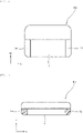
- FIG. 4 is a plan view showing an example of a shape of an electronic component 50 including the secondary battery 1.
- the secondary battery 1 is arranged in a space substantially half in the lateral direction W.
- the secondary battery 1 has the first external electrode 1a and the second external electrode 1b facing each other in the longitudinal direction L. Also in this case, in a state where the electronic component 50 is accommodated in the cavity 11 of the carrier sheet 10, because the first external electrode 1a of the secondary battery 1 is in contact with the first electrode 21, and the second external electrode 1b is in contact with the second electrode 22, when the first conductive line 31 and the second conductive line 32 are connected to an external power supply and a DC voltage is applied, the secondary batteries 1 of all the electronic components 50 can be charged.
- FIG. 5 is a side view showing an example of another shape of an electronic component 51 including the secondary battery 1.
- the secondary battery 1 is arranged in a space substantially half in the thickness direction T.
- the secondary battery 1 has the first external electrode 1a and the second external electrode 1b facing each other in the longitudinal direction L.
- the electronic component 51 needs to be accommodated in the cavity 11 such that the first external electrode 1a of the secondary battery 1 is in contact with the first electrode 21 and the second external electrode 1b thereof is in contact with the second electrode 22.
- the secondary batteries 1 of all the electronic components 51 can be charged in the state where the electronic components 51 are accommodated in the cavities 11 of the carrier sheet 10.
- a movement suppression mechanism for suppressing movement of a secondary battery 1 or an electronic component including the secondary battery 1 is provided in each of a plurality of cavities 11.
- FIG. 6 is a sectional view at a position of a first external electrode 1a of the secondary battery 1 when a carrier sheet 10 is viewed in the longitudinal direction L.
- a groove 12 is provided in the cavity 11.
- the groove 12 is formed along the longitudinal direction L and has the dimension in the lateral direction W that is slightly larger than the dimension in the lateral direction W of the secondary battery 1 or the electronic component including the secondary battery 1 to be accommodated.
- the secondary battery 1 or the electronic component including the secondary battery 1 is fitted in the groove 12.
- the description is made assuming that the secondary battery 1 is fitted.
- the movement in the lateral direction W of the secondary battery 1 to be accommodated can be restricted.
- the electrical connection between the first external electrode 1a of the secondary battery 1 and a first electrode 21 and the electrical connection between a second external electrode 1b and a second electrode 22 can be ensured, and the secondary battery 1 can be reliably charged.
- the shape of a secondary battery 1 or an electronic component including the secondary battery 1 accommodated in a cavity 11 of a carrier sheet 10 may be a substantially square shape in plan view.
- the secondary battery 1 or the electronic component having a substantially square shape in plan view is accommodated in the cavity 11, it is conceivable that the secondary battery 1 or the electronic component is accommodated in a state of being erroneously rotated by 90° in the horizontal direction.
- a first electrode 21 and a second electrode 22, which are a pair of electrodes, are formed not only on both end sides in the longitudinal direction L of the cavity 11 but also on both end sides in the lateral direction W thereof.
- FIG. 7 is a plan view schematically showing a shape of the first electrode 21 and the second electrode 22 formed on a bottom surface 11a of the cavity 11.
- the first electrode 21 has an L shape in plan view, and is formed on the side of a first end 11b of the cavity 11 in the longitudinal direction L and on the side of a second end 11c of the cavity 11 in the lateral direction W. However, the first electrode 21 is not in contact with a fourth end 11e of the cavity 11 facing the second end 11c in the lateral direction W.
- the second electrode 22 has an L shape in plan view, and is formed on the side of a third end 11d of the cavity 11 facing the first end 11b in the longitudinal direction L and on the side of the fourth end 11e in the lateral direction W. However, the second electrode 22 is not in contact with the second end 11c of the cavity 11 in the lateral direction W.
- first electrode 21 and the second electrode 22 have the L shape, despite the case of the secondary battery 1 to be accommodated being accommodated in a state of being erroneously rotated by 90° in the horizontal direction, a first external electrode 1a of the secondary battery 1 is in contact with one of the first electrode 21 and the second electrode 22, and a second external electrode 1b is in contact with the other of the first electrode 21 and the second electrode 22. As a result, the secondary battery 1 can be reliably charged. The same applies to the electronic component including the secondary battery 1 accommodated in the cavity 11.
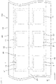
- FIG. 8 is a plan view showing a configuration of a package 100 in a fourth embodiment.
- the plurality of cavities 11 are formed in one row, but in the package 100 in the fourth embodiment, a plurality of cavities 11 are formed in two rows. That is, the plurality of cavities 11 are also formed in the lateral direction W of a carrier sheet 10.
- Two second conductive lines 32 are provided in accordance with the fact that the cavities 11 are formed in two rows. As shown in FIG. 8 , each of the second conductive lines 32 is electrically connected to second electrodes 22 of the cavities 11 located adjacent to each other.
- first conductive line 31 is provided between the plurality of cavities 11 provided in two rows.
- the first conductive line 31 is electrically connected to first electrodes 21 of the cavities 11 located on both sides.
- the plurality of secondary batteries 1 accommodated in the cavities 11 formed in two rows can be simultaneously charged.
- the plurality of cavities 11 may be formed in a plurality of rows of two or more rows.
- the longitudinal direction of the cavity 11 coincides with the longitudinal direction L of the carrier sheet 10.
- a cavity 11 is provided such that the longitudinal direction of the cavity 11 coincides with the lateral direction W of a carrier sheet 10.
- FIG. 9 is a plan view showing a configuration of the package 100 in the fifth embodiment.
- the carrier sheet 10 is provided with the cavities 11 such that the longitudinal direction of the cavity 11 having a rectangular shape in plan view coincides with the lateral direction W of the carrier sheet 10.
- a first conductive line 31 is electrically connected to a first electrode 21, and a second conductive line 32 is electrically connected to a second electrode 22. Therefore, by connecting the first conductive line 31 and the second conductive line 32 to an external power supply and applying a DC voltage, the plurality of secondary batteries 1 accommodated in the cavities 11 can be simultaneously charged.
- the package 100 in the second embodiment has the configuration in which the groove 12 is provided in the cavity 11 as the movement suppression mechanism for suppressing movement of the secondary battery 1 or the electronic component including the secondary battery 1.
- an adhesive member may be provided on the bottom surface of the cavity 11, and the secondary battery 1 or the electronic component to be accommodated may be bonded and fixed by the adhesive member.
Landscapes
- Engineering & Computer Science (AREA)
- Chemical & Material Sciences (AREA)
- Chemical Kinetics & Catalysis (AREA)
- Electrochemistry (AREA)
- General Chemical & Material Sciences (AREA)
- Power Engineering (AREA)
- Manufacturing & Machinery (AREA)
- Battery Mounting, Suspending (AREA)
- Packages (AREA)
- Secondary Cells (AREA)
- Connection Of Batteries Or Terminals (AREA)
Abstract
Description
- The present invention relates to a package that accommodates a secondary battery or an electronic component including the secondary battery, and a method of charging the secondary battery accommodated in the package.
-
Patent Document 1 discloses a series of electronic components including a long carrier tape in which a plurality of cavities is formed along a longitudinal direction, an electronic component accommodated in each of the cavities, and a cover film bonded to the carrier tape so as to cover the cavities. - As an example of a usage mode of the series of electronic components, for example, a usage mode is conceivable in which the secondary battery charged in advance is transported to a manufacturing factory of an electronic device in a state of being accommodated in a cavity, and in the factory as a transport destination, the secondary battery is taken out from the carrier tape by having the cover film peeled off and is used to manufacture the electronic device.
- Patent Document 1:
Japanese Patent Application Laid-Open No. 2004-268916 A - However, despite a case of the secondary battery being charged in advance before being accommodated in the cavity of the carrier tape, the capacity of the secondary battery decreases due to self-discharge if the time that has passed is long before the secondary battery is actually used. In that case, the secondary batteries need to be taken out one by one from the carrier tape and to be charged again, which takes time and effort.
- The present invention has been made to solve the above problem, and an object of the present invention is to provide a package that can charge a plurality of secondary batteries or an electronic component including the secondary battery that are accommodated in a carrier sheet without having the secondary batteries or the electronic component taken out from the carrier sheet, and a method of charging the secondary battery accommodated in the package.
- The package of the present invention includes:
- a cavity that accommodates a secondary battery having a pair of external electrodes or an electronic component including the secondary battery;
- a carrier sheet having a long shape and in which a plurality of the cavities are formed along a longitudinal direction;
- a first electrode and a second electrode that are configured to charge the secondary battery;
- a first conductive line electrically connected to a plurality of the first electrodes; and
- a second conductive line electrically connected to a plurality of the second electrodes,
- the first electrode and the second electrode being formed in the cavity, and
- the first conductive line and the second conductive line being formed in the carrier sheet.
- The cavities may be formed in plural numbers also in a lateral direction orthogonal to the longitudinal direction of the carrier sheet.
- The first electrode may be formed on one end side of the cavity, and the second electrode may be formed on the other end side of the cavity.
- Further, the first electrode may be formed on a side of a first end of the cavity in the longitudinal direction and on a side of a second end of the cavity in the lateral direction orthogonal to the longitudinal direction, and
the second electrode may be formed on a side of a third end of the cavity facing the first end in the longitudinal direction and on a side of a fourth end of the cavity facing the second end in the lateral direction. - The cavity may be provided with a movement suppression mechanism configured to suppress movement of the secondary battery or the electronic component.
- The package may further include a cover sheet that is bonded to the carrier sheet in a manner of covering an opening of the cavity in which the secondary battery or the electronic component is accommodated, and
the cover sheet may include a protrusion that abuts to the secondary battery or the electronic component in a state where the cover sheet is bonded to the carrier sheet. - In a direction in which the first electrode and the second electrode face each other, the cavity and the secondary battery may have a difference in dimensions which may be smaller than a difference in dimensions between the first electrode and the second electrode.
- A method of charging a secondary battery includes the steps of:
- accommodating the secondary battery in the cavity of any one of the above-described packages in a manner that one of a pair of external electrodes of the secondary battery is in contact with the first electrode and the other of the pair is in contact with the second electrode; and
- applying a direct current (DC) voltage to the first conductive line and the second conductive line.
- According to the package of the present invention, the secondary battery can be charged by applying the DC voltage between the first conductive line and the second conductive line in a state where the secondary battery having the pair of external electrodes or the electronic component including the secondary battery is accommodated in the cavity of the carrier sheet. As a result, despite the case of the capacity of the secondary battery charged before being accommodated in the cavity of the carrier sheet decreasing due to self-discharge, the secondary battery can be charged before being taken out from the carrier sheet. In addition, because the secondary battery can be charged before being taken out from the carrier sheet, the secondary battery or the electronic component including the secondary battery can be accommodated in the carrier sheet without charging the secondary battery.
- In addition, according to the method of charging the secondary battery according to the present invention, the secondary battery can be charged by applying the DC voltage between the first conductive line and the second conductive line in the state where the secondary battery having the pair of external electrodes or the electronic component including the secondary battery is accommodated in the cavity of the carrier sheet.
-
-
FIG. 1 is a plan view showing a configuration of a package in a first embodiment of the present invention. -
FIG. 2 is a sectional view taken along a line II-II of the package shown inFIG. 1 . -
FIG. 3 is a diagram showing a positional relationship between a secondary battery and a cavity when the secondary battery is displaced in a longitudinal direction, in which (a) shows a state of being displaced to a side of a first electrode, and (b) shows a state of being displaced to a side of a second electrode. -
FIG. 4 is a plan view showing an example of a shape of an electronic component including a secondary battery. -
FIG. 5 is a side view showing an example of another shape of an electronic component including a secondary battery. -
FIG. 6 is a sectional view at a position of the first external electrode of the secondary battery when the carrier sheet is viewed in a longitudinal direction. -
FIG. 7 is a plan view schematically showing a shape of the first electrode and the second electrode formed on a bottom surface of the cavity. -
FIG. 8 is a plan view showing a configuration of a package in a fourth embodiment. -
FIG. 9 is a plan view showing a configuration of a package in a fifth embodiment. - Hereinafter, features of the present invention are specifically described with reference to embodiments of the present invention.
-
FIG. 1 is a plan view showing a configuration of apackage 100 in a first embodiment of the present invention.FIG. 2 is a sectional view taken along a line II-II of thepackage 100 shown inFIG. 1 . - The
package 100 in the first embodiment includes acavity 11 for accommodating thesecondary battery 1 having a pair of external electrodes or an electronic component including thesecondary battery 1, along carrier sheet 10 in which a plurality ofcavities 11 are formed along a longitudinal direction L, afirst electrode 21 and asecond electrode 22 for charging thesecondary battery 1, a firstconductive line 31 electrically connected to the plurality offirst electrodes 21, and a secondconductive line 32 electrically connected to the plurality ofsecond electrodes 22. - The
package 100 in the present embodiment further includes acover sheet 40. - The
carrier sheet 10 is made of material having flexibility, such as paper or synthetic resin. The dimension of thecarrier sheet 10 in a lateral direction W is, for example, 10 mm, and the dimension in a thickness direction T is, for example, 3 mm. These dimensions are appropriately changed depending on the size of thesecondary battery 1 to be accommodated. The dimension of thecarrier sheet 10 in the longitudinal direction L can be an optional dimension. - Note that optional two directions among the longitudinal direction L, the lateral direction W, and the thickness direction T are directions orthogonal to each other.
- The
cavity 11 formed in thecarrier sheet 10 is a space for accommodating thesecondary battery 1 or the electronic component including thesecondary battery 1. Here, as shown inFIGS. 1 and2 , a description is given assuming that thesecondary battery 1 is accommodated in each of the plurality ofcavities 11. The plurality ofcavities 11 are formed, for example, at equal intervals along the longitudinal direction L of thecarrier sheet 10. In the present embodiment, thecavity 11 is formed such that the longitudinal direction of thecavity 11 having a rectangular shape in plan view coincides with the longitudinal direction L of thecarrier sheet 10. - The
cavity 11 has a size that can fully accommodate thesecondary battery 1 in plan view. However, the dimension of thecavity 11 in the lateral direction is shorter than the dimension in the longitudinal direction of thesecondary battery 1 to be accommodated. For example, the dimensions of thecavity 11 in the longitudinal direction L, the lateral direction W, and the thickness direction T shown inFIGS. 1 and2 are 4 mm, 3 mm, and 2 mm, respectively. - In the
cavity 11, thefirst electrode 21 and thesecond electrode 22 for charging thesecondary battery 1 are formed. One of thefirst electrode 21 and thesecond electrode 22 is a positive electrode, and the other is a negative electrode. As described later, one of thefirst electrode 21 and thesecond electrode 22 is in contact with one of a firstexternal electrode 1a and a secondexternal electrode 1b, which are a pair of external electrodes of thesecondary battery 1 to be accommodated, and the other of thefirst electrode 21 and thesecond electrode 22 is in contact with the other of the firstexternal electrode 1a and the secondexternal electrode 1b of thesecondary battery 1. - In the present embodiment, in a
bottom surface 11a of thecavity 11, thefirst electrode 21 is formed on one end side in the longitudinal direction L, and thesecond electrode 22 is formed on the other end side in the longitudinal direction L. In the present embodiment, the dimension in the lateral direction of thefirst electrode 21 and thesecond electrode 22 is the same as the dimension in the lateral direction W of thecavity 11. - The first
conductive line 31 and the secondconductive line 32 are formed on thecarrier sheet 10 and are made of material having conductivity. As described above, the firstconductive line 31 is electrically connected to the plurality offirst electrodes 21, and the secondconductive line 32 is electrically connected to the plurality ofsecond electrodes 22. That is, all thefirst electrodes 21 and all thesecond electrodes 22 are respectively connected in parallel. - The
secondary battery 1 that can be charged and discharged has the firstexternal electrode 1a and the secondexternal electrode 1b which are the pair of external electrodes. One of the firstexternal electrode 1a and the secondexternal electrode 1b is a positive electrode, and the other is a negative electrode. In the present embodiment, thesecondary battery 1 has a substantially rectangular parallelepiped shape. - There is no particular limitation on the type of the
secondary battery 1, but thesecondary battery 1 is preferably an all-solid-state battery that can perform constant voltage (CV) charging and is less likely to deteriorate after being discharged to 0 V. For example, as thesecondary battery 1, the all-solid-state battery having a nominal voltage of 2.0 V and a capacity of 0.1 mAh can be used. - In a state where the
secondary battery 1 is accommodated in thecavity 11 of thecarrier sheet 10, as shown inFIGS. 1 and2 , the firstexternal electrode 1a is in contact with thefirst electrode 21, and the secondexternal electrode 1b is in contact with thesecond electrode 22. However, the firstexternal electrode 1a may be in contact with thesecond electrode 22, and the secondexternal electrode 1b may be in contact with thefirst electrode 21. In this state, when the firstconductive line 31 and the secondconductive line 32 are connected to an external power supply and a DC voltage is applied, the DC voltage is applied between the firstexternal electrode 1a and the secondexternal electrode 1b of thesecondary battery 1, and thesecondary battery 1 is charged. - That is, the method of charging the
secondary battery 1 includes the steps of: - (a) accommodating the
secondary battery 1 in thecavity 11 of thepackage 100 such that one of the pair ofexternal electrodes secondary battery 1 is in contact with thefirst electrode 21 and the other is in contact with thesecond electrode 22; and - (b) applying a DC voltage to the first
conductive line 31 and the secondconductive line 32. - The
secondary battery 1 is charged by, for example, the CV charging in which a constant voltage is applied. As described above, because all thefirst electrodes 21 and all thesecond electrodes 22 are respectively connected in parallel, when a DC voltage is applied between the firstconductive line 31 and the secondconductive line 32, all thesecondary batteries 1 accommodated in thecavity 11 can be charged at simultaneously. - For example, by transporting the
package 100 accommodating the plurality ofsecondary batteries 1 to a manufacturing factory of electronic devices using thesecondary batteries 1, and applying a DC voltage between the firstconductive line 31 and the secondconductive line 32 in the manufacturing factory of the electronic devices, all thesecondary batteries 1 are charged. In this case, thesecondary batteries 1 can be accommodated in thecarrier sheet 10 and shipped without being charged in advance. In addition, despite in a case of thesecondary batteries 1 being charged in advance in a state of being accommodated in thecarrier sheet 10 before thepackage 100 is shipped, because thesecondary batteries 1 can be charged before being taken out from thecarrier sheet 10, a decrease in capacity due to self-discharge can be compensated by charging. In either case, the fully chargedsecondary battery 1 can be mounted on the electronic device. - In addition, in the
package 100 of the present embodiment, thesecondary batteries 1 do not need to be taken out one by one from thecarrier sheet 10 before being charged individually, but all thesecondary batteries 1 accommodated in thecavities 11 can be simultaneously charged, which is highly convenient. - The
cavity 11 has a size that causes the firstexternal electrode 1a of thesecondary battery 1 to come into contact with thefirst electrode 21 and the secondexternal electrode 1b to come into contact with thesecond electrode 22 despite a case of the accommodatedsecondary battery 1 moving and being displaced in position. -
FIG. 3 is a diagram showing a positional relationship between thesecondary battery 1 and thecavity 11 when thesecondary battery 1 is displaced in the longitudinal direction L, in which (a) shows a state of being displaced toward thefirst electrode 21 and (b) shows a state of being displaced toward thesecond electrode 22. As shown inFIGS. 3(a) and (b) , despite the case of thesecondary battery 1 moving in the longitudinal direction L and being displaced, the firstexternal electrode 1a of thesecondary battery 1 is in contact with thefirst electrode 21, and the secondexternal electrode 1b is in contact with thesecond electrode 22. - In order to realize the above configuration, in a direction in which the
first electrode 21 and thesecond electrode 22 face each other, a dimension L1 of thecavity 11 and a dimension L2 of thesecondary battery 1 has a difference L3 (= L1 - L2) therebetween, the difference L3 being configured to be smaller than a dimension of thefirst electrode 21 and a dimension L4 of thesecond electrode 22. - In the present embodiment, both the
first electrode 21 and thesecond electrode 22 are formed such that the dimension in the lateral direction W is the same as the dimension in the lateral direction W of thebottom surface 11a of thecavity 11. Therefore, despite the case of thesecondary battery 1 moving in the lateral direction W and being displaced, the firstexternal electrode 1a of thesecondary battery 1 is in contact with thefirst electrode 21, and the secondexternal electrode 1b thereof is in contact with thesecond electrode 22. - That is, in a state where the
secondary battery 1 is accommodated in thecavity 11, despite the case of thesecondary battery 1 moving, because the firstexternal electrode 1a is in contact with thefirst electrode 21 and the secondexternal electrode 1b is in contact with thesecond electrode 22, thesecondary battery 1 can be reliably charged. - The
cover sheet 40 is bonded to thecarrier sheet 10 so as to cover the opening of thecavity 11 in which thesecondary battery 1 or the electronic component including thesecondary battery 1 is accommodated. Thecover sheet 40 is made of, for example, a synthetic resin film. Thecover sheet 40 and thecarrier sheet 10 are bonded together, for example, with an adhesive interposed therebetween. By bonding thecover sheet 40 to thecarrier sheet 10 in a manner of covering the opening of thecavity 11 in which thesecondary battery 1 or the electronic component including thesecondary battery 1 is accommodated, the accommodatedsecondary battery 1 or electronic component can be suppressed from coming out of thecavity 11 during the transportation of thepackage 100, and thesecondary battery 1 or the electronic component can be reliably transported. - The
cover sheet 40 is provided with aprotrusion 41 that abuts to thesecondary battery 1 or the electronic component including thesecondary battery 1 in a state where thecover sheet 40 is bonded thecarrier sheet 10.FIG. 2 shows a state in which thesecondary battery 1 is accommodated in thecavity 11, and theprotrusion 41 provided on thecover sheet 40 abuts to thesecondary battery 1 to press thesecondary battery 1 from above. By providing theprotrusion 41 on thecover sheet 40, the protrusion comes into contact with thesecondary battery 1 accommodated in thecavity 11 to suppress the movement of thesecondary battery 1 in the thickness direction T, and the electrical connection between the firstexternal electrode 1a and thefirst electrode 21 and the electrical connection between the secondexternal electrode 1b and thesecond electrode 22 of thesecondary battery 1 can be reliably achieved. As a result, thesecondary battery 1 can be reliably charged. - Note that a configuration in which the
protrusion 41 is omitted from thecover sheet 40 may be adopted. - As described above, the electronic component including the
secondary battery 1 can also be accommodated in thecavity 11 of thecarrier sheet 10. -
FIG. 4 is a plan view showing an example of a shape of anelectronic component 50 including thesecondary battery 1. In theelectronic component 50 shown inFIG. 4 , thesecondary battery 1 is arranged in a space substantially half in the lateral direction W. Thesecondary battery 1 has the firstexternal electrode 1a and the secondexternal electrode 1b facing each other in the longitudinal direction L. Also in this case, in a state where theelectronic component 50 is accommodated in thecavity 11 of thecarrier sheet 10, because the firstexternal electrode 1a of thesecondary battery 1 is in contact with thefirst electrode 21, and the secondexternal electrode 1b is in contact with thesecond electrode 22, when the firstconductive line 31 and the secondconductive line 32 are connected to an external power supply and a DC voltage is applied, thesecondary batteries 1 of all theelectronic components 50 can be charged. -
FIG. 5 is a side view showing an example of another shape of anelectronic component 51 including thesecondary battery 1. In theelectronic component 51 shown inFIG. 5 , thesecondary battery 1 is arranged in a space substantially half in the thickness direction T. Thesecondary battery 1 has the firstexternal electrode 1a and the secondexternal electrode 1b facing each other in the longitudinal direction L. In this case, theelectronic component 51 needs to be accommodated in thecavity 11 such that the firstexternal electrode 1a of thesecondary battery 1 is in contact with thefirst electrode 21 and the secondexternal electrode 1b thereof is in contact with thesecond electrode 22. Also in this case, thesecondary batteries 1 of all theelectronic components 51 can be charged in the state where theelectronic components 51 are accommodated in thecavities 11 of thecarrier sheet 10. - In a
package 100 in the second embodiment, a movement suppression mechanism for suppressing movement of asecondary battery 1 or an electronic component including thesecondary battery 1 is provided in each of a plurality ofcavities 11. -
FIG. 6 is a sectional view at a position of a firstexternal electrode 1a of thesecondary battery 1 when acarrier sheet 10 is viewed in the longitudinal direction L. Here, as the movement suppression mechanism, agroove 12 is provided in thecavity 11. Thegroove 12 is formed along the longitudinal direction L and has the dimension in the lateral direction W that is slightly larger than the dimension in the lateral direction W of thesecondary battery 1 or the electronic component including thesecondary battery 1 to be accommodated. - The
secondary battery 1 or the electronic component including thesecondary battery 1 is fitted in thegroove 12. Here, as shown inFIG. 6 , the description is made assuming that thesecondary battery 1 is fitted. - By accommodating the
secondary battery 1 so as to be fitted in thegroove 12 when thesecondary battery 1 is accommodated in thecavity 11 of thecarrier sheet 10, the movement in the lateral direction W of thesecondary battery 1 to be accommodated can be restricted. As a result, the electrical connection between the firstexternal electrode 1a of thesecondary battery 1 and afirst electrode 21 and the electrical connection between a secondexternal electrode 1b and asecond electrode 22 can be ensured, and thesecondary battery 1 can be reliably charged. - The shape of a
secondary battery 1 or an electronic component including thesecondary battery 1 accommodated in acavity 11 of acarrier sheet 10 may be a substantially square shape in plan view. In this case, when thesecondary battery 1 or the electronic component having a substantially square shape in plan view is accommodated in thecavity 11, it is conceivable that thesecondary battery 1 or the electronic component is accommodated in a state of being erroneously rotated by 90° in the horizontal direction. - In a
package 100 in the third embodiment, afirst electrode 21 and asecond electrode 22, which are a pair of electrodes, are formed not only on both end sides in the longitudinal direction L of thecavity 11 but also on both end sides in the lateral direction W thereof. -
FIG. 7 is a plan view schematically showing a shape of thefirst electrode 21 and thesecond electrode 22 formed on abottom surface 11a of thecavity 11. - The
first electrode 21 has an L shape in plan view, and is formed on the side of afirst end 11b of thecavity 11 in the longitudinal direction L and on the side of asecond end 11c of thecavity 11 in the lateral direction W. However, thefirst electrode 21 is not in contact with afourth end 11e of thecavity 11 facing thesecond end 11c in the lateral direction W. - The
second electrode 22 has an L shape in plan view, and is formed on the side of athird end 11d of thecavity 11 facing thefirst end 11b in the longitudinal direction L and on the side of thefourth end 11e in the lateral direction W. However, thesecond electrode 22 is not in contact with thesecond end 11c of thecavity 11 in the lateral direction W. - Because the
first electrode 21 and thesecond electrode 22 have the L shape, despite the case of thesecondary battery 1 to be accommodated being accommodated in a state of being erroneously rotated by 90° in the horizontal direction, a firstexternal electrode 1a of thesecondary battery 1 is in contact with one of thefirst electrode 21 and thesecond electrode 22, and a secondexternal electrode 1b is in contact with the other of thefirst electrode 21 and thesecond electrode 22. As a result, thesecondary battery 1 can be reliably charged. The same applies to the electronic component including thesecondary battery 1 accommodated in thecavity 11. -
FIG. 8 is a plan view showing a configuration of apackage 100 in a fourth embodiment. In thepackage 100 in the first embodiment shown inFIG. 1 , the plurality ofcavities 11 are formed in one row, but in thepackage 100 in the fourth embodiment, a plurality ofcavities 11 are formed in two rows. That is, the plurality ofcavities 11 are also formed in the lateral direction W of acarrier sheet 10. - Two second
conductive lines 32 are provided in accordance with the fact that thecavities 11 are formed in two rows. As shown inFIG. 8 , each of the secondconductive lines 32 is electrically connected tosecond electrodes 22 of thecavities 11 located adjacent to each other. - On the other hand, only one first
conductive line 31 is provided between the plurality ofcavities 11 provided in two rows. The firstconductive line 31 is electrically connected tofirst electrodes 21 of thecavities 11 located on both sides. - However, a configuration in which two first
conductive lines 31 are provided and one secondconductive line 32 is provided may be adopted. - Also in the
package 100 in the present embodiment, by connecting the firstconductive line 31 and the secondconductive lines 32 to an external power supply and applying a DC voltage, the plurality ofsecondary batteries 1 accommodated in thecavities 11 formed in two rows can be simultaneously charged. - Note that in the
carrier sheet 10, the plurality ofcavities 11 may be formed in a plurality of rows of two or more rows. - In the
package 100 in the first embodiment shown inFIG. 1 , the longitudinal direction of thecavity 11 coincides with the longitudinal direction L of thecarrier sheet 10. On the other hand, in apackage 100 in a fifth embodiment, acavity 11 is provided such that the longitudinal direction of thecavity 11 coincides with the lateral direction W of acarrier sheet 10. -
FIG. 9 is a plan view showing a configuration of thepackage 100 in the fifth embodiment. As shown inFIG. 9 , thecarrier sheet 10 is provided with thecavities 11 such that the longitudinal direction of thecavity 11 having a rectangular shape in plan view coincides with the lateral direction W of thecarrier sheet 10. Also in this configuration, a firstconductive line 31 is electrically connected to afirst electrode 21, and a secondconductive line 32 is electrically connected to asecond electrode 22. Therefore, by connecting the firstconductive line 31 and the secondconductive line 32 to an external power supply and applying a DC voltage, the plurality ofsecondary batteries 1 accommodated in thecavities 11 can be simultaneously charged. - The present invention is not limited to the above embodiments, and various applications and modifications can be made within the scope of the present invention.
- The
package 100 in the second embodiment has the configuration in which thegroove 12 is provided in thecavity 11 as the movement suppression mechanism for suppressing movement of thesecondary battery 1 or the electronic component including thesecondary battery 1. In order to suppress the movement of thesecondary battery 1 accommodated in thecavity 11 or the electronic component including thesecondary battery 1, an adhesive member may be provided on the bottom surface of thecavity 11, and thesecondary battery 1 or the electronic component to be accommodated may be bonded and fixed by the adhesive member. -
- 1:
- Secondary battery
- 1a:
- First external electrode of secondary battery
- 1b:
- Second external electrode of secondary battery
- 10:
- Carrier sheet
- 11:
- Cavity
- 12:
- Groove in cavity
- 21:
- First electrode
- 22:
- Second electrode
- 31:
- First conductive line
- 32:
- Second conductive line
- 40:
- Cover sheet
- 41:
- Protrusion
- 50, 51:
- Electronic component
- 100:
- Package
Claims (8)
- A package comprising:a cavity that accommodates a secondary battery having a pair of external electrodes or an electronic component including the secondary battery;a carrier sheet having a long shape and in which a plurality of the cavities are formed along a longitudinal direction;a first electrode and a second electrode that are configured to charge the secondary battery;a first conductive line electrically connected to a plurality of the first electrodes; anda second conductive line electrically connected to a plurality of the second electrodes,the first electrode and the second electrode being formed in the cavity, andthe first conductive line and the second conductive line being formed in the carrier sheet.
- The package according to claim 1, wherein the cavities are formed in plural numbers also in a lateral direction orthogonal to the longitudinal direction of the carrier sheet.
- The package according to claim 1 or 2, wherein the first electrode is formed on a one end side of the cavity, and the second electrode is formed on another end side of the cavity.
- The package according to claim 1 or 2, whereinthe first electrode is formed on a side of a first end of the cavity in the longitudinal direction and on a side of a second end of the cavity in the lateral direction orthogonal to the longitudinal direction, andthe second electrode is formed on a side of a third end of the cavity facing the first end in the longitudinal direction and on a side of a fourth end of the cavity facing the second end in the lateral direction.
- The package according to any one of claims 1 to 4, wherein the cavity is provided with a movement suppression mechanism configured to suppress movement of the secondary battery or the electronic component.
- The package according to any one of claims 1 to 5, further comprising a cover sheet that is bonded to the carrier sheet in a manner of covering an opening of the cavity in which the secondary battery or the electronic component is accommodated, wherein
the cover sheet includes a protrusion that abuts to the secondary battery or the electronic component in a state where the cover sheet is bonded to the carrier sheet. - The package according to any one of claims 1 to 6, wherein, in a direction in which the first electrode and the second electrode face each other, the cavity and the secondary battery have a difference in dimensions that is smaller than a difference in dimensions between the first electrode and the second electrode.
- A method of charging a secondary battery comprising the steps of:accommodating the secondary battery in the cavity of the package according to any one of claims 1 to 7 in a manner that a one of a pair of external electrodes of the secondary battery is in contact with the first electrode and another of the pair is in contact with the second electrode; andapplying a direct current voltage to the first conductive line and the second conductive line.
Applications Claiming Priority (2)
| Application Number | Priority Date | Filing Date | Title |
|---|---|---|---|
| JP2019108085 | 2019-06-10 | ||
| PCT/JP2020/016851 WO2020250569A1 (en) | 2019-06-10 | 2020-04-17 | Container and method for charging secondary battery |
Publications (2)
| Publication Number | Publication Date |
|---|---|
| EP3982459A1 true EP3982459A1 (en) | 2022-04-13 |
| EP3982459A4 EP3982459A4 (en) | 2024-12-25 |
Family
ID=73781739
Family Applications (1)
| Application Number | Title | Priority Date | Filing Date |
|---|---|---|---|
| EP20823122.5A Pending EP3982459A4 (en) | 2019-06-10 | 2020-04-17 | CONTAINER AND METHOD FOR CHARGING A SECONDARY BATTERY |
Country Status (5)
| Country | Link |
|---|---|
| US (1) | US12155248B2 (en) |
| EP (1) | EP3982459A4 (en) |
| JP (1) | JP7238981B2 (en) |
| CN (1) | CN113924681B (en) |
| WO (1) | WO2020250569A1 (en) |
Family Cites Families (9)
| Publication number | Priority date | Publication date | Assignee | Title |
|---|---|---|---|---|
| JPS59134569A (en) * | 1983-01-24 | 1984-08-02 | Toppan Printing Co Ltd | Flat plate type battery |
| JP2746143B2 (en) * | 1994-09-29 | 1998-04-28 | ミノルタ株式会社 | Battery storage case and case storage battery |
| JP3111020B2 (en) * | 1996-03-22 | 2000-11-20 | 株式会社フジシール | Blister package for dry cell |
| JP2004268916A (en) | 2003-03-04 | 2004-09-30 | Murata Mfg Co Ltd | Series of electronic components |
| JP2005347129A (en) * | 2004-06-03 | 2005-12-15 | Fuji Photo Film Co Ltd | Charger |
| JP2015026840A (en) * | 2013-10-25 | 2015-02-05 | 株式会社村田製作所 | Ceramic electronic component and taping electronic component series |
| US10211443B2 (en) * | 2014-09-10 | 2019-02-19 | Cellink Corporation | Battery interconnects |
| JP6873035B2 (en) * | 2015-04-28 | 2021-05-19 | 株式会社カネカ | Packaged items |
| US11271410B2 (en) * | 2017-04-24 | 2022-03-08 | 9609385 Canada Inc. | Battery harvesting device and method |
-
2020
- 2020-04-17 CN CN202080042273.6A patent/CN113924681B/en active Active
- 2020-04-17 EP EP20823122.5A patent/EP3982459A4/en active Pending
- 2020-04-17 WO PCT/JP2020/016851 patent/WO2020250569A1/en not_active Ceased
- 2020-04-17 JP JP2021525929A patent/JP7238981B2/en active Active
-
2021
- 2021-11-01 US US17/515,930 patent/US12155248B2/en active Active
Also Published As
| Publication number | Publication date |
|---|---|
| CN113924681B (en) | 2025-05-30 |
| US20220052539A1 (en) | 2022-02-17 |
| CN113924681A (en) | 2022-01-11 |
| EP3982459A4 (en) | 2024-12-25 |
| US12155248B2 (en) | 2024-11-26 |
| JP7238981B2 (en) | 2023-03-14 |
| WO2020250569A1 (en) | 2020-12-17 |
| JPWO2020250569A1 (en) | 2020-12-17 |
Similar Documents
| Publication | Publication Date | Title |
|---|---|---|
| CN202308182U (en) | Secondary battery | |
| EP3736883B1 (en) | Battery module including secondary battery and bus bar | |
| EP3761393B1 (en) | Battery module comprising inner cover | |
| US10811721B2 (en) | Accumulator device | |
| US9871243B2 (en) | Electric accumulation device | |
| US9799928B2 (en) | Battery pack | |
| WO2023051104A1 (en) | Connector, battery pack, and electric device | |
| US9685648B2 (en) | Bus bar attachment device and bus bar attachment method | |
| US12288890B2 (en) | Power storage module | |
| JP6690831B2 (en) | Secondary battery | |
| CN116315409A (en) | Batteries, battery modules and electrical equipment | |
| KR20150115358A (en) | Secondary battery | |
| US12155248B2 (en) | Package and method of charging secondary battery | |
| US11545705B2 (en) | Secondary battery and battery pack including the same | |
| KR102505609B1 (en) | Battery pack | |
| KR20110005581A (en) | Polymer battery pack | |
| KR102172845B1 (en) | Battery pack | |
| US20150228960A1 (en) | Battery pack | |
| EP4207431A1 (en) | Battery pack connector | |
| US8795878B2 (en) | Secondary battery | |
| US11817541B2 (en) | Battery pack | |
| US12327883B2 (en) | Battery pack connector |
Legal Events
| Date | Code | Title | Description |
|---|---|---|---|
| STAA | Information on the status of an ep patent application or granted ep patent |
Free format text: STATUS: THE INTERNATIONAL PUBLICATION HAS BEEN MADE |
|
| PUAI | Public reference made under article 153(3) epc to a published international application that has entered the european phase |
Free format text: ORIGINAL CODE: 0009012 |
|
| STAA | Information on the status of an ep patent application or granted ep patent |
Free format text: STATUS: REQUEST FOR EXAMINATION WAS MADE |
|
| 17P | Request for examination filed |
Effective date: 20211119 |
|
| AK | Designated contracting states |
Kind code of ref document: A1 Designated state(s): AL AT BE BG CH CY CZ DE DK EE ES FI FR GB GR HR HU IE IS IT LI LT LU LV MC MK MT NL NO PL PT RO RS SE SI SK SM TR |
|
| DAV | Request for validation of the european patent (deleted) | ||
| DAX | Request for extension of the european patent (deleted) | ||
| A4 | Supplementary search report drawn up and despatched |
Effective date: 20241122 |
|
| RIC1 | Information provided on ipc code assigned before grant |
Ipc: H02J 7/00 20060101ALI20241118BHEP Ipc: H01M 50/209 20210101ALI20241118BHEP Ipc: H01M 10/46 20060101ALI20241118BHEP Ipc: H01M 10/44 20060101AFI20241118BHEP |
|
| GRAP | Despatch of communication of intention to grant a patent |
Free format text: ORIGINAL CODE: EPIDOSNIGR1 |
|
| STAA | Information on the status of an ep patent application or granted ep patent |
Free format text: STATUS: GRANT OF PATENT IS INTENDED |
|
| RIC1 | Information provided on ipc code assigned before grant |
Ipc: H01M 10/44 20060101AFI20260106BHEP Ipc: H01M 10/46 20060101ALI20260106BHEP Ipc: H01M 50/209 20210101ALI20260106BHEP Ipc: H02J 7/00 20060101ALI20260106BHEP Ipc: H02J 7/50 20260101ALI20260106BHEP Ipc: H02J 7/70 20260101ALI20260106BHEP |
|
| INTG | Intention to grant announced |
Effective date: 20260204 |