EP3982141A1 - Battery management apparatus, battery management method, battery pack and electric vehicle - Google Patents
Battery management apparatus, battery management method, battery pack and electric vehicle Download PDFInfo
- Publication number
- EP3982141A1 EP3982141A1 EP20866793.1A EP20866793A EP3982141A1 EP 3982141 A1 EP3982141 A1 EP 3982141A1 EP 20866793 A EP20866793 A EP 20866793A EP 3982141 A1 EP3982141 A1 EP 3982141A1
- Authority
- EP
- European Patent Office
- Prior art keywords
- battery
- capacity curve
- differential capacity
- value
- charge
- Prior art date
- Legal status (The legal status is an assumption and is not a legal conclusion. Google has not performed a legal analysis and makes no representation as to the accuracy of the status listed.)
- Granted
Links
- 238000007726 management method Methods 0.000 title claims abstract description 41
- 230000015556 catabolic process Effects 0.000 claims abstract description 38
- 238000006731 degradation reaction Methods 0.000 claims abstract description 38
- 238000007599 discharging Methods 0.000 abstract description 4
- 230000008859 change Effects 0.000 description 27
- 230000007423 decrease Effects 0.000 description 15
- 238000004891 communication Methods 0.000 description 8
- 238000000034 method Methods 0.000 description 7
- 230000001174 ascending effect Effects 0.000 description 6
- 230000008569 process Effects 0.000 description 6
- 230000000694 effects Effects 0.000 description 3
- 230000006870 function Effects 0.000 description 3
- 230000004044 response Effects 0.000 description 3
- 239000000126 substance Substances 0.000 description 3
- WHXSMMKQMYFTQS-UHFFFAOYSA-N Lithium Chemical compound [Li] WHXSMMKQMYFTQS-UHFFFAOYSA-N 0.000 description 2
- HBBGRARXTFLTSG-UHFFFAOYSA-N Lithium ion Chemical compound [Li+] HBBGRARXTFLTSG-UHFFFAOYSA-N 0.000 description 2
- PXHVJJICTQNCMI-UHFFFAOYSA-N Nickel Chemical compound [Ni] PXHVJJICTQNCMI-UHFFFAOYSA-N 0.000 description 2
- 238000004364 calculation method Methods 0.000 description 2
- 238000010586 diagram Methods 0.000 description 2
- 229910052744 lithium Inorganic materials 0.000 description 2
- 229910001416 lithium ion Inorganic materials 0.000 description 2
- 238000012986 modification Methods 0.000 description 2
- 230000004048 modification Effects 0.000 description 2
- 238000012545 processing Methods 0.000 description 2
- 239000004065 semiconductor Substances 0.000 description 2
- 230000007704 transition Effects 0.000 description 2
- XUIMIQQOPSSXEZ-UHFFFAOYSA-N Silicon Chemical compound [Si] XUIMIQQOPSSXEZ-UHFFFAOYSA-N 0.000 description 1
- 238000004458 analytical method Methods 0.000 description 1
- 238000003491 array Methods 0.000 description 1
- OJIJEKBXJYRIBZ-UHFFFAOYSA-N cadmium nickel Chemical compound [Ni].[Cd] OJIJEKBXJYRIBZ-UHFFFAOYSA-N 0.000 description 1
- 238000011161 development Methods 0.000 description 1
- 230000004069 differentiation Effects 0.000 description 1
- 239000007772 electrode material Substances 0.000 description 1
- 238000004146 energy storage Methods 0.000 description 1
- 238000005516 engineering process Methods 0.000 description 1
- 230000005669 field effect Effects 0.000 description 1
- 229910052739 hydrogen Inorganic materials 0.000 description 1
- 239000001257 hydrogen Substances 0.000 description 1
- 230000003446 memory effect Effects 0.000 description 1
- 229910044991 metal oxide Inorganic materials 0.000 description 1
- 150000004706 metal oxides Chemical class 0.000 description 1
- 229910052759 nickel Inorganic materials 0.000 description 1
- QELJHCBNGDEXLD-UHFFFAOYSA-N nickel zinc Chemical compound [Ni].[Zn] QELJHCBNGDEXLD-UHFFFAOYSA-N 0.000 description 1
- 230000001151 other effect Effects 0.000 description 1
- 229910052710 silicon Inorganic materials 0.000 description 1
- 239000010703 silicon Substances 0.000 description 1
- 239000007787 solid Substances 0.000 description 1
- 230000003068 static effect Effects 0.000 description 1
- 238000006467 substitution reaction Methods 0.000 description 1
Images


Classifications
-
- H—ELECTRICITY
- H02—GENERATION; CONVERSION OR DISTRIBUTION OF ELECTRIC POWER
- H02J—CIRCUIT ARRANGEMENTS OR SYSTEMS FOR SUPPLYING OR DISTRIBUTING ELECTRIC POWER; SYSTEMS FOR STORING ELECTRIC ENERGY
- H02J7/00—Circuit arrangements for charging or depolarising batteries or for supplying loads from batteries
- H02J7/0047—Circuit arrangements for charging or depolarising batteries or for supplying loads from batteries with monitoring or indicating devices or circuits
-
- G—PHYSICS
- G01—MEASURING; TESTING
- G01R—MEASURING ELECTRIC VARIABLES; MEASURING MAGNETIC VARIABLES
- G01R31/00—Arrangements for testing electric properties; Arrangements for locating electric faults; Arrangements for electrical testing characterised by what is being tested not provided for elsewhere
- G01R31/36—Arrangements for testing, measuring or monitoring the electrical condition of accumulators or electric batteries, e.g. capacity or state of charge [SoC]
- G01R31/392—Determining battery ageing or deterioration, e.g. state of health
-
- B—PERFORMING OPERATIONS; TRANSPORTING
- B60—VEHICLES IN GENERAL
- B60L—PROPULSION OF ELECTRICALLY-PROPELLED VEHICLES; SUPPLYING ELECTRIC POWER FOR AUXILIARY EQUIPMENT OF ELECTRICALLY-PROPELLED VEHICLES; ELECTRODYNAMIC BRAKE SYSTEMS FOR VEHICLES IN GENERAL; MAGNETIC SUSPENSION OR LEVITATION FOR VEHICLES; MONITORING OPERATING VARIABLES OF ELECTRICALLY-PROPELLED VEHICLES; ELECTRIC SAFETY DEVICES FOR ELECTRICALLY-PROPELLED VEHICLES
- B60L3/00—Electric devices on electrically-propelled vehicles for safety purposes; Monitoring operating variables, e.g. speed, deceleration or energy consumption
- B60L3/12—Recording operating variables ; Monitoring of operating variables
-
- B—PERFORMING OPERATIONS; TRANSPORTING
- B60—VEHICLES IN GENERAL
- B60L—PROPULSION OF ELECTRICALLY-PROPELLED VEHICLES; SUPPLYING ELECTRIC POWER FOR AUXILIARY EQUIPMENT OF ELECTRICALLY-PROPELLED VEHICLES; ELECTRODYNAMIC BRAKE SYSTEMS FOR VEHICLES IN GENERAL; MAGNETIC SUSPENSION OR LEVITATION FOR VEHICLES; MONITORING OPERATING VARIABLES OF ELECTRICALLY-PROPELLED VEHICLES; ELECTRIC SAFETY DEVICES FOR ELECTRICALLY-PROPELLED VEHICLES
- B60L58/00—Methods or circuit arrangements for monitoring or controlling batteries or fuel cells, specially adapted for electric vehicles
- B60L58/10—Methods or circuit arrangements for monitoring or controlling batteries or fuel cells, specially adapted for electric vehicles for monitoring or controlling batteries
- B60L58/12—Methods or circuit arrangements for monitoring or controlling batteries or fuel cells, specially adapted for electric vehicles for monitoring or controlling batteries responding to state of charge [SoC]
-
- B—PERFORMING OPERATIONS; TRANSPORTING
- B60—VEHICLES IN GENERAL
- B60L—PROPULSION OF ELECTRICALLY-PROPELLED VEHICLES; SUPPLYING ELECTRIC POWER FOR AUXILIARY EQUIPMENT OF ELECTRICALLY-PROPELLED VEHICLES; ELECTRODYNAMIC BRAKE SYSTEMS FOR VEHICLES IN GENERAL; MAGNETIC SUSPENSION OR LEVITATION FOR VEHICLES; MONITORING OPERATING VARIABLES OF ELECTRICALLY-PROPELLED VEHICLES; ELECTRIC SAFETY DEVICES FOR ELECTRICALLY-PROPELLED VEHICLES
- B60L58/00—Methods or circuit arrangements for monitoring or controlling batteries or fuel cells, specially adapted for electric vehicles
- B60L58/10—Methods or circuit arrangements for monitoring or controlling batteries or fuel cells, specially adapted for electric vehicles for monitoring or controlling batteries
- B60L58/16—Methods or circuit arrangements for monitoring or controlling batteries or fuel cells, specially adapted for electric vehicles for monitoring or controlling batteries responding to battery ageing, e.g. to the number of charging cycles or the state of health [SoH]
-
- B—PERFORMING OPERATIONS; TRANSPORTING
- B60—VEHICLES IN GENERAL
- B60L—PROPULSION OF ELECTRICALLY-PROPELLED VEHICLES; SUPPLYING ELECTRIC POWER FOR AUXILIARY EQUIPMENT OF ELECTRICALLY-PROPELLED VEHICLES; ELECTRODYNAMIC BRAKE SYSTEMS FOR VEHICLES IN GENERAL; MAGNETIC SUSPENSION OR LEVITATION FOR VEHICLES; MONITORING OPERATING VARIABLES OF ELECTRICALLY-PROPELLED VEHICLES; ELECTRIC SAFETY DEVICES FOR ELECTRICALLY-PROPELLED VEHICLES
- B60L58/00—Methods or circuit arrangements for monitoring or controlling batteries or fuel cells, specially adapted for electric vehicles
- B60L58/10—Methods or circuit arrangements for monitoring or controlling batteries or fuel cells, specially adapted for electric vehicles for monitoring or controlling batteries
- B60L58/18—Methods or circuit arrangements for monitoring or controlling batteries or fuel cells, specially adapted for electric vehicles for monitoring or controlling batteries of two or more battery modules
-
- G—PHYSICS
- G01—MEASURING; TESTING
- G01R—MEASURING ELECTRIC VARIABLES; MEASURING MAGNETIC VARIABLES
- G01R31/00—Arrangements for testing electric properties; Arrangements for locating electric faults; Arrangements for electrical testing characterised by what is being tested not provided for elsewhere
- G01R31/36—Arrangements for testing, measuring or monitoring the electrical condition of accumulators or electric batteries, e.g. capacity or state of charge [SoC]
- G01R31/3644—Constructional arrangements
- G01R31/3648—Constructional arrangements comprising digital calculation means, e.g. for performing an algorithm
-
- G—PHYSICS
- G01—MEASURING; TESTING
- G01R—MEASURING ELECTRIC VARIABLES; MEASURING MAGNETIC VARIABLES
- G01R31/00—Arrangements for testing electric properties; Arrangements for locating electric faults; Arrangements for electrical testing characterised by what is being tested not provided for elsewhere
- G01R31/36—Arrangements for testing, measuring or monitoring the electrical condition of accumulators or electric batteries, e.g. capacity or state of charge [SoC]
- G01R31/382—Arrangements for monitoring battery or accumulator variables, e.g. SoC
- G01R31/3842—Arrangements for monitoring battery or accumulator variables, e.g. SoC combining voltage and current measurements
-
- G—PHYSICS
- G01—MEASURING; TESTING
- G01R—MEASURING ELECTRIC VARIABLES; MEASURING MAGNETIC VARIABLES
- G01R31/00—Arrangements for testing electric properties; Arrangements for locating electric faults; Arrangements for electrical testing characterised by what is being tested not provided for elsewhere
- G01R31/36—Arrangements for testing, measuring or monitoring the electrical condition of accumulators or electric batteries, e.g. capacity or state of charge [SoC]
- G01R31/396—Acquisition or processing of data for testing or for monitoring individual cells or groups of cells within a battery
-
- H—ELECTRICITY
- H01—ELECTRIC ELEMENTS
- H01M—PROCESSES OR MEANS, e.g. BATTERIES, FOR THE DIRECT CONVERSION OF CHEMICAL ENERGY INTO ELECTRICAL ENERGY
- H01M10/00—Secondary cells; Manufacture thereof
- H01M10/42—Methods or arrangements for servicing or maintenance of secondary cells or secondary half-cells
- H01M10/425—Structural combination with electronic components, e.g. electronic circuits integrated to the outside of the casing
-
- H—ELECTRICITY
- H01—ELECTRIC ELEMENTS
- H01M—PROCESSES OR MEANS, e.g. BATTERIES, FOR THE DIRECT CONVERSION OF CHEMICAL ENERGY INTO ELECTRICAL ENERGY
- H01M10/00—Secondary cells; Manufacture thereof
- H01M10/42—Methods or arrangements for servicing or maintenance of secondary cells or secondary half-cells
- H01M10/44—Methods for charging or discharging
-
- H—ELECTRICITY
- H01—ELECTRIC ELEMENTS
- H01M—PROCESSES OR MEANS, e.g. BATTERIES, FOR THE DIRECT CONVERSION OF CHEMICAL ENERGY INTO ELECTRICAL ENERGY
- H01M10/00—Secondary cells; Manufacture thereof
- H01M10/42—Methods or arrangements for servicing or maintenance of secondary cells or secondary half-cells
- H01M10/48—Accumulators combined with arrangements for measuring, testing or indicating the condition of cells, e.g. the level or density of the electrolyte
-
- H—ELECTRICITY
- H02—GENERATION; CONVERSION OR DISTRIBUTION OF ELECTRIC POWER
- H02J—CIRCUIT ARRANGEMENTS OR SYSTEMS FOR SUPPLYING OR DISTRIBUTING ELECTRIC POWER; SYSTEMS FOR STORING ELECTRIC ENERGY
- H02J7/00—Circuit arrangements for charging or depolarising batteries or for supplying loads from batteries
- H02J7/00032—Circuit arrangements for charging or depolarising batteries or for supplying loads from batteries characterised by data exchange
- H02J7/00036—Charger exchanging data with battery
-
- H—ELECTRICITY
- H02—GENERATION; CONVERSION OR DISTRIBUTION OF ELECTRIC POWER
- H02J—CIRCUIT ARRANGEMENTS OR SYSTEMS FOR SUPPLYING OR DISTRIBUTING ELECTRIC POWER; SYSTEMS FOR STORING ELECTRIC ENERGY
- H02J7/00—Circuit arrangements for charging or depolarising batteries or for supplying loads from batteries
- H02J7/0013—Circuit arrangements for charging or depolarising batteries or for supplying loads from batteries acting upon several batteries simultaneously or sequentially
- H02J7/0025—Sequential battery discharge in systems with a plurality of batteries
-
- H—ELECTRICITY
- H02—GENERATION; CONVERSION OR DISTRIBUTION OF ELECTRIC POWER
- H02J—CIRCUIT ARRANGEMENTS OR SYSTEMS FOR SUPPLYING OR DISTRIBUTING ELECTRIC POWER; SYSTEMS FOR STORING ELECTRIC ENERGY
- H02J7/00—Circuit arrangements for charging or depolarising batteries or for supplying loads from batteries
- H02J7/0029—Circuit arrangements for charging or depolarising batteries or for supplying loads from batteries with safety or protection devices or circuits
- H02J7/0031—Circuit arrangements for charging or depolarising batteries or for supplying loads from batteries with safety or protection devices or circuits using battery or load disconnect circuits
-
- H—ELECTRICITY
- H02—GENERATION; CONVERSION OR DISTRIBUTION OF ELECTRIC POWER
- H02J—CIRCUIT ARRANGEMENTS OR SYSTEMS FOR SUPPLYING OR DISTRIBUTING ELECTRIC POWER; SYSTEMS FOR STORING ELECTRIC ENERGY
- H02J7/00—Circuit arrangements for charging or depolarising batteries or for supplying loads from batteries
- H02J7/0047—Circuit arrangements for charging or depolarising batteries or for supplying loads from batteries with monitoring or indicating devices or circuits
- H02J7/0048—Detection of remaining charge capacity or state of charge [SOC]
-
- H—ELECTRICITY
- H02—GENERATION; CONVERSION OR DISTRIBUTION OF ELECTRIC POWER
- H02J—CIRCUIT ARRANGEMENTS OR SYSTEMS FOR SUPPLYING OR DISTRIBUTING ELECTRIC POWER; SYSTEMS FOR STORING ELECTRIC ENERGY
- H02J7/00—Circuit arrangements for charging or depolarising batteries or for supplying loads from batteries
- H02J7/0047—Circuit arrangements for charging or depolarising batteries or for supplying loads from batteries with monitoring or indicating devices or circuits
- H02J7/005—Detection of state of health [SOH]
-
- H—ELECTRICITY
- H02—GENERATION; CONVERSION OR DISTRIBUTION OF ELECTRIC POWER
- H02J—CIRCUIT ARRANGEMENTS OR SYSTEMS FOR SUPPLYING OR DISTRIBUTING ELECTRIC POWER; SYSTEMS FOR STORING ELECTRIC ENERGY
- H02J7/00—Circuit arrangements for charging or depolarising batteries or for supplying loads from batteries
- H02J7/007—Regulation of charging or discharging current or voltage
- H02J7/00712—Regulation of charging or discharging current or voltage the cycle being controlled or terminated in response to electric parameters
- H02J7/00714—Regulation of charging or discharging current or voltage the cycle being controlled or terminated in response to electric parameters in response to battery charging or discharging current
-
- H—ELECTRICITY
- H02—GENERATION; CONVERSION OR DISTRIBUTION OF ELECTRIC POWER
- H02J—CIRCUIT ARRANGEMENTS OR SYSTEMS FOR SUPPLYING OR DISTRIBUTING ELECTRIC POWER; SYSTEMS FOR STORING ELECTRIC ENERGY
- H02J7/00—Circuit arrangements for charging or depolarising batteries or for supplying loads from batteries
- H02J7/007—Regulation of charging or discharging current or voltage
- H02J7/00712—Regulation of charging or discharging current or voltage the cycle being controlled or terminated in response to electric parameters
- H02J7/007182—Regulation of charging or discharging current or voltage the cycle being controlled or terminated in response to electric parameters in response to battery voltage
-
- B—PERFORMING OPERATIONS; TRANSPORTING
- B60—VEHICLES IN GENERAL
- B60L—PROPULSION OF ELECTRICALLY-PROPELLED VEHICLES; SUPPLYING ELECTRIC POWER FOR AUXILIARY EQUIPMENT OF ELECTRICALLY-PROPELLED VEHICLES; ELECTRODYNAMIC BRAKE SYSTEMS FOR VEHICLES IN GENERAL; MAGNETIC SUSPENSION OR LEVITATION FOR VEHICLES; MONITORING OPERATING VARIABLES OF ELECTRICALLY-PROPELLED VEHICLES; ELECTRIC SAFETY DEVICES FOR ELECTRICALLY-PROPELLED VEHICLES
- B60L2240/00—Control parameters of input or output; Target parameters
- B60L2240/40—Drive Train control parameters
- B60L2240/54—Drive Train control parameters related to batteries
- B60L2240/547—Voltage
-
- B—PERFORMING OPERATIONS; TRANSPORTING
- B60—VEHICLES IN GENERAL
- B60L—PROPULSION OF ELECTRICALLY-PROPELLED VEHICLES; SUPPLYING ELECTRIC POWER FOR AUXILIARY EQUIPMENT OF ELECTRICALLY-PROPELLED VEHICLES; ELECTRODYNAMIC BRAKE SYSTEMS FOR VEHICLES IN GENERAL; MAGNETIC SUSPENSION OR LEVITATION FOR VEHICLES; MONITORING OPERATING VARIABLES OF ELECTRICALLY-PROPELLED VEHICLES; ELECTRIC SAFETY DEVICES FOR ELECTRICALLY-PROPELLED VEHICLES
- B60L2240/00—Control parameters of input or output; Target parameters
- B60L2240/40—Drive Train control parameters
- B60L2240/54—Drive Train control parameters related to batteries
- B60L2240/549—Current
-
- B—PERFORMING OPERATIONS; TRANSPORTING
- B60—VEHICLES IN GENERAL
- B60Y—INDEXING SCHEME RELATING TO ASPECTS CROSS-CUTTING VEHICLE TECHNOLOGY
- B60Y2200/00—Type of vehicle
- B60Y2200/90—Vehicles comprising electric prime movers
- B60Y2200/91—Electric vehicles
-
- H—ELECTRICITY
- H01—ELECTRIC ELEMENTS
- H01M—PROCESSES OR MEANS, e.g. BATTERIES, FOR THE DIRECT CONVERSION OF CHEMICAL ENERGY INTO ELECTRICAL ENERGY
- H01M10/00—Secondary cells; Manufacture thereof
- H01M10/42—Methods or arrangements for servicing or maintenance of secondary cells or secondary half-cells
- H01M10/425—Structural combination with electronic components, e.g. electronic circuits integrated to the outside of the casing
- H01M2010/4271—Battery management systems including electronic circuits, e.g. control of current or voltage to keep battery in healthy state, cell balancing
-
- H—ELECTRICITY
- H01—ELECTRIC ELEMENTS
- H01M—PROCESSES OR MEANS, e.g. BATTERIES, FOR THE DIRECT CONVERSION OF CHEMICAL ENERGY INTO ELECTRICAL ENERGY
- H01M2220/00—Batteries for particular applications
- H01M2220/20—Batteries in motive systems, e.g. vehicle, ship, plane
-
- Y—GENERAL TAGGING OF NEW TECHNOLOGICAL DEVELOPMENTS; GENERAL TAGGING OF CROSS-SECTIONAL TECHNOLOGIES SPANNING OVER SEVERAL SECTIONS OF THE IPC; TECHNICAL SUBJECTS COVERED BY FORMER USPC CROSS-REFERENCE ART COLLECTIONS [XRACs] AND DIGESTS
- Y02—TECHNOLOGIES OR APPLICATIONS FOR MITIGATION OR ADAPTATION AGAINST CLIMATE CHANGE
- Y02E—REDUCTION OF GREENHOUSE GAS [GHG] EMISSIONS, RELATED TO ENERGY GENERATION, TRANSMISSION OR DISTRIBUTION
- Y02E60/00—Enabling technologies; Technologies with a potential or indirect contribution to GHG emissions mitigation
- Y02E60/10—Energy storage using batteries
-
- Y—GENERAL TAGGING OF NEW TECHNOLOGICAL DEVELOPMENTS; GENERAL TAGGING OF CROSS-SECTIONAL TECHNOLOGIES SPANNING OVER SEVERAL SECTIONS OF THE IPC; TECHNICAL SUBJECTS COVERED BY FORMER USPC CROSS-REFERENCE ART COLLECTIONS [XRACs] AND DIGESTS
- Y02—TECHNOLOGIES OR APPLICATIONS FOR MITIGATION OR ADAPTATION AGAINST CLIMATE CHANGE
- Y02T—CLIMATE CHANGE MITIGATION TECHNOLOGIES RELATED TO TRANSPORTATION
- Y02T10/00—Road transport of goods or passengers
- Y02T10/60—Other road transportation technologies with climate change mitigation effect
- Y02T10/70—Energy storage systems for electromobility, e.g. batteries
Definitions
- the present disclosure relates to technology for determining degradation information of a battery.
- degradation information associated with degradation of a battery is determined from a capacity curve indicating a correlation between the voltage and capacity of the battery.
- the capacity curve has a capacity range in which voltage changes are not clearly observed, it is difficult to accurately determine the degradation information of the battery.
- differential capacity analysis determines the degradation information of the battery from a differential capacity curve.
- DCA differential capacity analysis
- the present disclosure is designed to solve the above-described problem, and therefore the present disclosure is directed to providing a battery management apparatus, a battery management method, a battery pack and an electric vehicle for determining degradation information of a battery from at least four differential capacity curves acquired by performing the charge process and the discharge process at least once using each of at least two constant currents having different current rates.
- a battery management apparatus includes a sensing unit configured to detect a voltage and a current of a battery, and configured to output a sensing signal indicating the detected voltage and the detected current, and a control unit operably coupled to the sensing unit.
- the control unit determines a first differential capacity curve based on a first voltage history and a first capacity history of the battery acquired for a first period during which the battery is charged with a first constant current.
- the control unit determines a second differential capacity curve based on a second voltage history and a second capacity history of the battery acquired for a second period during which the battery is discharged with the first constant current.
- the control unit determines a third differential capacity curve based on a third voltage history and a third capacity history of the battery acquired for a third period during which the battery is charged with a second constant current that is different from the first constant current.
- the control unit determines a fourth differential capacity curve based on a fourth voltage history and a fourth capacity history of the battery acquired for a fourth period during which the battery is discharged with the second constant current.
- the control unit detects a first charge feature point from the first differential capacity curve.
- the control unit detects a first discharge feature point from the second differential capacity curve.
- the control unit detects a second charge feature point from the third differential capacity curve.
- the control unit detects a second discharge feature point from the fourth differential capacity curve.
- the control unit determines degradation information of the battery based on first and second charge feature values and first and second discharge feature values.
- the first and second charge feature values are voltage values of the first and second charge feature points respectively.
- the first and second discharge feature values are voltage values of the first and second discharge feature points respectively.
- the first charge feature point is a peak located in a first predetermined order among peaks of the first differential capacity curve.
- the first discharge feature point is a peak located in the first predetermined order among peaks of the second differential capacity curve.
- the second charge feature point is a peak located in the first predetermined order among peaks of the third differential capacity curve.
- the second discharge feature point is a peak located in the first predetermined order among peaks of the fourth differential capacity curve.
- the control unit may determine a first hysteresis value indicating an absolute value of difference between the first charge feature value and the first discharge feature value.
- the control unit may determine a second hysteresis value indicating an absolute value of difference between the second charge feature value and the second discharge feature value.
- the degradation information may include the first and second hysteresis values.
- the degradation information may further include a first difference value which is an absolute value of difference between the first hysteresis value and the second hysteresis value.
- the control unit may further detect a third charge feature point from the first differential capacity curve.
- the control unit may further detect a third discharge feature point from the second differential capacity curve.
- the control unit may further detect a fourth charge feature point from the third differential capacity curve.
- the control unit may further detect a fourth discharge feature point from the fourth differential capacity curve.
- the control unit may determine the degradation information further based on third and fourth charge feature values and third and fourth discharge feature values.
- the third and fourth charge feature values are voltage values of the third and fourth charge feature points respectively.
- the third and fourth discharge feature values are voltage values of the third and fourth discharge feature points respectively.
- the third charge feature point is a peak located in a second predetermined order among the peaks of the first differential capacity curve.
- the third discharge feature point is a peak located in the second predetermined order among the peaks of the second differential capacity curve.
- the fourth charge feature point is a peak located in the second predetermined order among the peaks of the third differential capacity curve.
- the fourth discharge feature point is a peak located in the second predetermined order among the peaks of the fourth differential capacity curve.
- the control unit may determine a third hysteresis value indicating an absolute value of difference between the third charge feature value and the third discharge charge feature value.
- the control unit may determine a fourth hysteresis value indicating an absolute value of difference between the fourth charge feature value and the fourth discharge feature value.
- the degradation information may further include the third and fourth hysteresis values.
- the degradation information may further include at least one of a second difference value which is an absolute value of difference between the third hysteresis value and the fourth hysteresis value, a third difference value which is an absolute value of difference between the first hysteresis value and the third hysteresis value, or a fourth difference value which is an absolute value of difference between the second hysteresis value and the fourth hysteresis value.
- a second difference value which is an absolute value of difference between the third hysteresis value and the fourth hysteresis value
- a third difference value which is an absolute value of difference between the first hysteresis value and the third hysteresis value
- a fourth difference value which is an absolute value of difference between the second hysteresis value and the fourth hysteresis value.
- the control unit may determine a maximum current rate allowable for charge and discharge of the battery based on the degradation information.
- a battery pack according to another aspect of the present disclosure includes the battery management apparatus.
- An electric vehicle includes the battery pack.
- a battery management method uses the battery management apparatus.
- the battery management method includes determining, by the control unit, the first differential capacity curve based on the first voltage history and the first capacity history of the battery acquired for the first period during which the battery is charged with the first constant current, determining, by the control unit, the second differential capacity curve based on the second voltage history and the second capacity history of the battery acquired for the second period during which the battery is discharged with the first constant current, determining, by the control unit, the third differential capacity curve based on the third voltage history and the third capacity history of the battery acquired for the third period during which the battery is charged with the second constant current, determining, by the control unit, the fourth differential capacity curve based on the fourth voltage history and the fourth capacity history of the battery acquired for the fourth period during which the battery is discharged with the second constant current, detecting, by the control unit, the first charge feature point from the first differential capacity curve, detecting, by the control unit, the first discharge feature point from the second differential capacity curve, detecting, by the control unit, the
- control unit refers to a processing unit of at least one function or operation, and may be implemented by hardware or software alone or in combination.
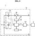
- FIG. 1 is a diagram exemplarily showing a configuration of an electrical system according to an embodiment of the present disclosure
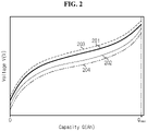
- FIG. 2 is a graph exemplarily showing first to fourth capacity curves determined by a battery management apparatus of FIG. 1 .
- the battery pack 10 is provided to be installed in an electrical system 1 (e.g., an electric vehicle), and includes a battery B, a switch SW and a battery management apparatus 100.
- an electrical system 1 e.g., an electric vehicle
- the battery B includes at least one unit cell.
- the unit cell may be, for example, a lithium ion battery.
- the type of the unit cell is not limited to the lithium ion battery, and any other type of battery cell that can be repeatedly recharged may be used as the unit cell.
- the switch SW is installed on a current path for the charge and discharge of the battery B. While the switch SW is turned on, the battery B may be charged and discharged.
- the switch SW may be a mechanical relay that is turned on or off by the magnetic force of a coil or a semiconductor switch such as a Metal Oxide Semiconductor Field Effect transistor (MOSFET). While the switch SW is turned off, the charge and discharge of the battery B is stopped.
- the switch SW may be turned on in response to a first switching signal from a switch driver 200.
- the switch SW may be turned off in response to a second switching signal from the switch driver 200.
- the battery management apparatus 100 is provided to determine degradation information of the battery B, and control the charge and discharge of the battery B based on the degradation information.
- the battery management apparatus 100 includes a sensing unit 110, a control unit 120 and a memory unit 130.
- the battery management apparatus 100 may further include at least one of an interface unit 140 or a switch driver 200.
- the sensing unit 110 includes a voltage sensor 111 and a current sensor 112.
- the voltage sensor 111 is electrically connected to the positive terminal and the negative terminal of the battery B.
- the voltage sensor 111 is configured to detect a voltage across the battery B at each unit time (e.g., 0.01 sec) while the battery B is charged or discharged.
- the current sensor 112 is installed on the current path for the charge and discharge of the battery B.
- the current sensor 112 is configured to detect a current of the battery B at each unit time while the battery B is charged or discharged.
- the sensing unit 110 is configured to periodically output a sensing signal indicating the voltage and the current of the battery B detected at each unit time to the control unit 120.
- the control unit 120 may be implemented in hardware using at least one of application specific integrated circuits (ASICs), digital signal processors (DSPs), digital signal processing devices (DSPDs), programmable logic devices (PLDs), field programmable gate arrays (FPGAs), microprocessors or electrical units for performing other functions.
- ASICs application specific integrated circuits
- DSPs digital signal processors
- DSPDs digital signal processing devices
- PLDs programmable logic devices
- FPGAs field programmable gate arrays
- microprocessors or electrical units for performing other functions.
- the control unit 120 is operably coupled to at least one of the sensing unit 110, the memory unit 130, the interface unit 140 or the switch driver 200.
- control unit 120 may command the switch driver 200 to turn on the switch SW. In other situations, the control unit 120 may command the switch driver 200 to turn off the switch SW.
- the control unit 120 is configured to acquire data indicating a voltage history, a current history and a capacity history of the battery B over a certain period by recording the sensing signal from the sensing unit 110 in the memory unit 130 in a sequential order.
- the history of a parameter refers to a time series change of the corresponding parameter over a certain period.
- the voltage history, the current history and the capacity history of the battery B may be those for the same or different periods.
- the capacity of the battery B at a specific time point indicates an amount of charges stored in the battery B at the time point.
- the control unit 120 may determine the capacity history from the current history of the battery B using ampere counting. For example, the capacity of the current cycle is equal to the sum of a capacity change and the capacity of the previous cycle, the capacity change obtained by multiplying the current detected in the current cycle by the unit time.
- the control unit 120 determines a first capacity curve 201, a second capacity curve 202, a third capacity curve 203 and a fourth capacity curve 204 of the battery B.
- Q max of FIG. 2 is the maximum capacity of the battery B, and may be the capacity of the battery B when the SOC of the battery B is 100% (i.e., when the battery B is fully charged). Q max gradually decreases as the battery B degrades.
- the first capacity curve 201 indicates a correlation between a first voltage history and a first capacity history, acquired for a period (hereinafter referred to as a "first period") during which the battery B is charged with a first constant current of a first current rate (e.g., 0.02 C) from a first state of charge (SOC) (e.g., 0%, 5%) to a second SOC (e.g., 95%, 100%) higher than the first SOC.
- SOC state of charge
- the first capacity curve 201 is based on the sensing signal periodically output by the sensing unit 110 for the first period.
- the control unit 120 may control the switch driver 200 to charge the battery B with the constant current of the first current rate for the first period.
- the second capacity curve 202 indicates a correlation between a second voltage history and a second capacity history, acquired for a period (hereinafter referred to as a "second period") during which the battery B is discharged with the first constant current from the second SOC to the first SOC.
- the second capacity curve 202 is based on the sensing signal periodically output by the sensing unit 110 for the second period.
- the control unit 120 may control the switch driver 200 to discharge the battery B with the second constant current for the second period.
- the third capacity curve 203 indicates a correlation between a third voltage history and a third capacity history, acquired for a period (hereinafter referred to as a "third period") during which the battery B is charged with a second constant current of a second current rate (e.g., 0.05 C) that is different from the first current rate from the first SOC to the second SOC.
- the third capacity curve 203 is based on the sensing signal periodically output by the sensing unit 110 for the third period.
- the control unit 120 may control the switch driver 200 to charge the battery B with the second constant current for the third period.
- the second current rate is higher than the first current rate.
- the fourth capacity curve 204 indicates a correlation between a fourth voltage history and a fourth capacity history, acquired for a period (hereinafter referred to as a "fourth period") during which the battery B is discharged with the second constant current from the second SOC to the first SOC.
- the fourth capacity curve 204 is based on the sensing signal periodically output by the sensing unit 110 for the fourth period.
- the control unit 120 may control the switch driver 200 to discharge the battery B with the constant current of the second current rate for the fourth period.
- the first to fourth periods do not overlap, and they are not limited to a particular order.
- the control unit 120 may control the charge and discharge of the battery B such that the time interval between two adjacent periods is equal to or less than a predetermined time (e.g., 5 hours). For example, when the first period is the earliest one, the second period comes after the first period, the third period comes after the second period and the fourth period comes after the third period, the control unit 120 may start the second period after a predetermined time (e.g., 3 hours) from the end time of the first period, may start the third period after the predetermined time from the end time of the second period, and may start the fourth period after the predetermined time from the end time of the third period.
- a predetermined time e.g., 3 hours
- the capacity curves 201, 202, 203, 204 there is a voltage difference between the capacity curves 201, 202, 203, 204 at the same capacity.
- a voltage difference between any two capacity curves results from a voltage drop across the battery B caused by the internal resistance of the battery B when the current flows through the battery B and the hysteresis characteristics of the battery B.
- the hysteresis characteristics are caused by a difference between the voltage at which phase transition occurs during the charge of the battery B and the voltage at which phase transition occurs during the discharge of the battery B, and as the battery B degrades, and as a larger current flows through the battery B, the hysteresis characteristics may appear more distinctly.
- the control unit 120 may determine a voltage change dV and a capacity change dQ of the battery B at each unit time from the first capacity curve 201.
- the control unit 120 may store, in the memory unit 130, a first data set indicating a correlation of the voltage V, the capacity Q, the voltage change dV and the capacity change dQ of the battery B at each unit time, determined from the first capacity curve 201.
- the control unit 120 may determine a first differential capacity curve from the first data set.
- the first differential capacity curve indicates a relationship between the voltage V of the battery B for the first period and a ratio dQ/dV of the capacity change dQ of the battery B to the voltage change dV of the battery B, and may be referred to as a first V-dQ/dV curve.
- the control unit 120 may determine a voltage change dV and a capacity change dQ of the battery B at each unit time from the second capacity curve 202.
- the control unit 120 may store, in the memory unit 130, a second data set indicating a correlation of the voltage V, the capacity Q, the voltage change dV and the capacity change dQ of the battery B at each unit time, determined from the second capacity curve 202.
- the control unit 120 may determine a second differential capacity curve from the second data set.
- the second differential capacity curve indicates a relationship between the voltage V of the battery B for the second period and a ratio dQ/dV of the capacity change dQ of the battery B to the voltage change dV of the battery B, and may be referred to as a second V-dQ/dV curve.
- the control unit 120 may determine a voltage change dV and a capacity change dQ of the battery B at each unit time from the third capacity curve 203.
- the control unit 120 may store, in the memory unit 130, a third data set indicating a correlation of the voltage V, the capacity Q, the voltage change dV and the capacity change dQ of the battery B at each unit time, determined from the third capacity curve 203.
- the control unit 120 may determine a third differential capacity curve from the third data set.
- the third differential capacity curve indicates a relationship between the voltage V of the battery B for the third period and a ratio dQ/dV of the capacity change dQ to the voltage change dV of the battery B, and may be referred to as a third V-dQ/dV curve.
- the control unit 120 may determine a voltage change dV and a capacity change dQ of the battery B at each unit time from the fourth capacity curve 204.
- the control unit 120 may store, in the memory unit 130, a fourth data set indicating a correlation of the voltage V, the capacity Q, the voltage change dV and the capacity change dQ of the battery B at each unit time, determined from the fourth capacity curve 204.
- the control unit 120 may determine a fourth differential capacity curve from the fourth data set.
- the fourth differential capacity curve indicates a relationship between the voltage V of the battery B for the fourth period and a ratio dQ/dV of the capacity change dQ to the voltage change dV of the battery B, and may be referred to as a fourth V-dQ/dV curve.
- dQ/dV is a differentiation value obtained by differentiating the capacity Q to the voltage V, and may be referred to as a 'differential capacity'.
- the memory unit 130 is operably coupled to the control unit 120.
- the memory unit 130 may be also operably coupled to the sensing unit 110.
- the memory unit 130 is configured to store the sensing signal from the sensing unit 110.
- the memory unit 130 may store data and programs required for the calculation operation by the control unit 120.
- the memory unit 130 may store data indicating the results of the calculation operation by the control unit 120.
- the memory unit 130 may include, for example, at least one type of storage medium of flash memory type, hard disk type, Solid State Disk (SSD) type, Silicon Disk Drive (SDD) type, multimedia card micro type, random access memory (RAM), static random access memory (SRAM), read-only memory (ROM), electrically erasable programmable read-only memory (EEPROM) or programmable read-only memory (PROM).
- flash memory type hard disk type
- SSD Solid State Disk
- SDD Silicon Disk Drive
- multimedia card micro type random access memory
- RAM random access memory
- SRAM static random access memory
- ROM read-only memory
- EEPROM electrically erasable programmable read-only memory
- PROM programmable read-only memory
- the switch driver 200 is electrically coupled to the battery management apparatus 100 and the switch SW.
- the switch driver 200 is configured to selectively output the first switching signal or the second switching signal to the switch SW in response to the command from the battery management apparatus 100.
- the interface unit 140 is configured to support the wired or wireless communication between the control unit 120 and a high-level controller 2 (e.g., an Electronic Control Unit (ECU)) of the electrical system 1.
- the wired communication may be, for example, controller area network (CAN) communication
- the wireless communication may be, for example, Zigbee or Bluetooth communication.
- the communication protocol is not limited to a particular type, and may include any type of communication protocol that supports the wired or wireless communication between the control unit 120 and the high-level controller 2.
- the interface unit 140 may include an output device such as a display or a speaker to provide the degradation information of the battery B determined by the control unit 120 in a form that allows the user to recognize.
- the interface unit 140 may include an input device such as a mouse and a keyboard to receive input data from the user.
- FIG. 3 is a graph exemplarily showing the first and second differential capacity curves corresponding to the first and second capacity curves of FIG. 2 with a one-to-one relationship
- FIG. 4 is a graph exemplarily showing the third and fourth differential capacity curves corresponding to the third and fourth capacity curves of FIG. 2 with a one-to-one relationship.
- the first differential capacity curve 301 may be determined from the first capacity curve 201.
- the second differential capacity curve 302 may be determined from the second capacity curve 202.
- the third differential capacity curve 303 may be determined from the third capacity curve 203.
- the fourth differential capacity curve 304 may be determined from the fourth capacity curve 204.
- each of the first differential capacity curve 301 and the third differential capacity curve 303 acquired through charging is shown on the upper part of FIGS. 3 and 4
- each of the first to fourth differential capacity curves 301, 302, 303, 304 relies on the electrode materials or the like of the battery B. Accordingly, even though the battery B degrades, the total number (or minimum number) of peaks of each of the first to fourth differential capacity curves 301, 302, 303, 304 may be constant. Each peak refers to the relative maximum point or the relative minimum point.
- the graphs of FIGS. 3 and 4 show that the first differential capacity curve 301 includes peaks P C1_1 , P C1_2 , P C1_3 , the second differential capacity curve 302 includes peaks P D1_1 , P D1_2 , P D1_3 , the third differential capacity curve 303 includes peaks P C2_1 , P C2_2 , P C2_3 , and the fourth differential capacity curve 304 includes peaks P D2_1 , P D2_2 , P D2_3 .
- Each of the peaks P C1_1 , P C1_2 , P C1_3 of the first differential capacity curve 301 may be referred to as a charge feature point of the first differential capacity curve 301.
- the control unit 120 may store charge feature values each indicating voltage values V C1_1 , V C1_2 , V C1_3 of the peaks P C1_1 , P C1_2 , P C1_3 in the memory unit 130.
- Each of the peaks P D1_1 , P D1_2 , P D1_3 of the second differential capacity curve 302 may be referred to as a discharge feature point of the second differential capacity curve 302.
- the control unit 120 may store discharge feature values each indicating voltage values V D1_1 , V D1_2 , V D1_3 of the peaks P D1_1 , P D1_2 , P D1_3 in the memory unit 130.
- Each of the peaks P C2_1 , P C2_2 , P C2_3 of the third differential capacity curve 303 may be referred to as a charge feature point of the third differential capacity curve 303.
- the control unit 120 may store charge feature values each indicating voltage values V C2_1 , V C2_2 , V C2_3 of the peaks P C2_1 , P C2_2 , P C2_3 in the memory unit 130.
- Each of the peaks P D2_1 , P D2_2 , P D2_3 of the fourth differential capacity curve 304 may be referred to as a discharge feature point of the fourth differential capacity curve 304.
- the control unit 120 may store discharge feature values each indicating voltage values V D2_1 , VD2 2, VD2 3 of the peaks P D2_1 , P D2_2 , P D2_3 in the memory unit 130.
- the first differential capacity curve 301 has the peak C1_1 , the peak C1_2 and the peak C1_3 in the ascending order of the voltage V.
- the second differential capacity curve 302 has the peak D1_1 , the peak D1_2 and the peak D1_3 in the ascending order of the voltage V.
- the third differential capacity curve 303 has the peak C2_1 , the peak C2_2 and the peak C2_3 in the ascending order of the voltage V.
- the fourth differential capacity curve 304 has the peak D2_1 , the peak D2_2 and the peak D2_3 in the ascending order of the voltage V.
- the charge feature value V C2_1 is larger than the charge feature value V C1_1
- the charge feature value V C2_2 is larger than the charge feature value V C1_2
- the charge feature value V C2_3 is larger than the charge feature value V C1_3 .
- the discharge feature value V D2_1 is smaller than the discharge feature value V D1_1
- the discharge feature value V D2_2 is smaller than the discharge feature value V D1_2
- the discharge feature value V D2_3 is smaller than the discharge feature value V D1_3 .
- a voltage difference between the charge feature point and the discharge feature point located in the same order of the third differential capacity curve 303 and the fourth differential capacity curve 304 is larger than a voltage difference between the charge feature point and the discharge feature point located in the same order of the first differential capacity curve 301 and the second differential capacity curve 302.
- a difference between the charge feature value V C2_1 and the discharge feature value V D2_1 is larger than a difference between the charge feature value V C1_1 and the discharge feature value V D1_1 .
- a difference between the charge feature value V C2_2 and the discharge feature value V D2_2 is larger than a difference between the charge feature value V C1_2 and the discharge feature value V D1_2 .
- a difference between the charge feature value V C2_3 and the discharge feature value V D2_3 is larger than a difference between the charge feature value V C1_3 and the discharge feature value V D1_3 .
- FIG. 5 is a flowchart exemplarily showing a battery management method according to a first embodiment of the present disclosure.
- step S500 the control unit 120 determines a first differential capacity curve 301, based on a first voltage history and a first capacity history of the battery B acquired for a first period during which the battery B is charged with a first constant current.
- step S505 the control unit 120 determines a second differential capacity curve 302 based on a second voltage history and a second capacity history of the battery B acquired for a second period during which the battery B is discharged with the first constant current.
- step S510 the control unit 120 determines a third differential capacity curve 303 based on a third voltage history and a third capacity history of the battery B acquired for a third period during which the battery B is charged with a second constant current.
- step S515 the control unit 120 determines a fourth differential capacity curve 304 based on a fourth voltage history and a fourth capacity history of the battery B acquired for a fourth period during which the battery B is discharged with the second constant current.
- the control unit 120 detects a first charge feature point from the first differential capacity curve 301.
- the first charge feature point may be a peak located in a first predetermined order among the peaks P C1_1 , P C1_2 , P C1_3 of the first differential capacity curve 301.
- the first predetermined order may be the first in the ascending order of voltage, and in this case, the peak C1_1 may be determined as the first charge feature point.
- the control unit 120 detects a first discharge feature point from the second differential capacity curve 302.
- the first discharge feature point may be a peak located in the first predetermined order among the peaks P D1_1 , P D1_2 , P D1_3 of the second differential capacity curve 302.
- the peak D1_1 may be determined as the first discharge feature point.
- the control unit 120 detects a second charge feature point from the third differential capacity curve 303.
- the second charge feature point may be a peak located in the first predetermined order among the peaks P C2_1 , P C2_2 , P C2_3 of the third differential capacity curve 303.
- the peak C2_1 may be determined as the second charge feature point.
- step S535 the control unit 120 detects a second discharge feature point from the fourth differential capacity curve 304.
- the second discharge feature point may be a peak located in the first predetermined order among the peaks P D2_1 , P D2_2 , P D2_3 of the fourth differential capacity curve 304.
- the peak D2_1 may be determined as the second discharge feature point.
- the control unit 120 determines degradation information of the battery B based on the first and second charge feature values and the first and second discharge feature values.
- the degradation information includes a first hysteresis value ⁇ V hys1 and a second hysteresis value ⁇ V hys2 .
- the first hysteresis value ⁇ V hys1 indicates an absolute value of difference between the first charge feature value V C1_1 and the first discharge feature value V D1 _ 1 .
- the second hysteresis value ⁇ V hys2 indicates an absolute value of difference between the second charge feature value V C2_1 and the second discharge feature value V D2_1 .
- the degradation information may further include a first difference value which is an absolute value of difference between the first hysteresis value ⁇ V hys1 and the second hysteresis value ⁇ V hys2 .
- step S545 the control unit 120 controls the charge and discharge of the battery B based on the degradation information of the battery B.
- the control unit 120 may decrease a maximum allowable current rate of the battery B, decrease an end-of-charge voltage of the battery B, or increase an end-of-discharge voltage of the battery B.
- the first threshold value may be preset, taking the electrical and chemical properties of the battery B into account.
- the maximum allowable current rate may be a maximum of current rate allowed for the charge and discharge of the battery B.
- the end-of-charge voltage may be a maximum of allowable voltage for the charge of the battery B.
- the end-of-discharge voltage may be a minimum of allowable voltage for the discharge of the battery B.
- the decrease in the maximum allowable current rate, the decrease in the end-of-charge voltage and the increase in the end-of-discharge voltage may be proportional to a ratio of the first difference value to the first threshold value. For example, when the first difference value is 1.1 times larger than the first threshold value, the maximum allowable current rate may decrease at the ratio of 1/1.1 to the previous one.
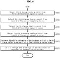
- FIG. 6 is a flowchart exemplarily showing a battery management method according to a second embodiment of the present disclosure.
- the battery management method according to the second embodiment includes the same steps S500 ⁇ S535 as the battery management method according to the first embodiment described above with reference to FIG. 5 .
- difference(s) from the battery management method according to the first embodiment will be described.
- the control unit 120 detects a third charge feature point from the first differential capacity curve 301.
- the third charge feature point may be a peak located in a second predetermined order among the peaks P C1_1 , P C1_2 , P C1_3 of the first differential capacity curve 301.
- the second predetermined order may be the third one in the ascending order of voltage, and in this case, the peak C1_3 may be determined as the third charge feature point.
- step S605 the control unit 120 detects a third discharge feature point from the second differential capacity curve 302.
- the third discharge feature point may be a peak located in the second predetermined order among the peaks P D1_1 , P D1_2 , P D1_3 of the second differential capacity curve 302.
- the peak D1_3 may be determined as the third discharge feature point.
- step S610 the control unit 120 detects a fourth charge feature point from the third differential capacity curve 303.
- the fourth charge feature point may be a peak located in the second predetermined order among the peaks P C2_1 , P C2_2 , P C2_3 of the third differential capacity curve 303.
- the peak C2_3 may be determined as the fourth charge feature point.
- the control unit 120 detects a fourth discharge feature point from the fourth differential capacity curve 304.
- the fourth discharge feature point may be a peak located in the second predetermined order among the peaks P D2_1 , P D2_2 , P D2_3 of the fourth differential capacity curve 304.
- the peak D2_3 may be determined as the fourth discharge feature point.
- step S620 the control unit 120 determines degradation information of the battery B based on the first to fourth charge feature values and the first to fourth discharge feature values.
- the degradation information includes first to fourth hysteresis values.
- the third hysteresis value ⁇ V hys3 indicates an absolute value of difference between the third charge feature value V C1_3 and the third discharge feature value V D1_3
- the fourth hysteresis value ⁇ V hys4 indicates an absolute value between difference between the fourth charge feature value V C2_3 and the fourth discharge feature value V D2_3 .
- the degradation information may further include a second difference value which is an absolute value of difference between the third hysteresis value ⁇ V hys3 and the fourth hysteresis value ⁇ V hys4 .
- the degradation information may further include a third difference value which is an absolute value of difference between the first hysteresis value ⁇ V hys1 and the third hysteresis value ⁇ V hys3 .
- the degradation information may further include a fourth difference value which is an absolute value of difference between the second hysteresis value ⁇ V hys2 and the fourth hysteresis value ⁇ V hys4 .
- step S625 the control unit 120 controls the charge and discharge of the battery B based on the degradation information of the battery B.
- the control unit 120 may decrease the maximum allowable current rate of the battery B, decrease the end-of-charge voltage of the battery B, or increase the end-of-discharge voltage of the battery B.
- Each of the second to fourth threshold values may be preset, taking the electrical and chemical properties of the battery B into account.
- the decrease in the maximum allowable current rate, the decrease in the end-of-charge voltage and the increase in the end-of-discharge voltage may be proportional to the largest one of a ratio of the first difference value to the first threshold value, a ratio of the second difference value to the second threshold value, a ratio of the third difference value to the third threshold value and a ratio of the fourth difference value to the fourth threshold value.
- the maximum allowable current rate may decrease at the ratio of 1/1.2 to the previous one.
- the control unit 120 may decrease the maximum allowable current rate of the battery B, decrease the end-of-charge voltage of the battery B, or increase the end-of-discharge voltage of the battery B.
- Each of the first and second threshold ranges may be preset, taking the electrical and chemical properties or the like of the battery B into account.
- the decrease in the maximum allowable current rate, the decrease in the end-of-charge voltage and the increase in the end-of-discharge voltage may be proportional to a larger one of a ratio of the second difference value to the first difference value and a ratio of the fourth difference value to the third difference value.
Landscapes
- Engineering & Computer Science (AREA)
- Power Engineering (AREA)
- General Physics & Mathematics (AREA)
- Physics & Mathematics (AREA)
- Life Sciences & Earth Sciences (AREA)
- Mechanical Engineering (AREA)
- Sustainable Development (AREA)
- Sustainable Energy (AREA)
- Transportation (AREA)
- Chemical & Material Sciences (AREA)
- Manufacturing & Machinery (AREA)
- Chemical Kinetics & Catalysis (AREA)
- Electrochemistry (AREA)
- General Chemical & Material Sciences (AREA)
- Medical Informatics (AREA)
- General Health & Medical Sciences (AREA)
- Health & Medical Sciences (AREA)
- Microelectronics & Electronic Packaging (AREA)
- Secondary Cells (AREA)
- Charge And Discharge Circuits For Batteries Or The Like (AREA)
- Tests Of Electric Status Of Batteries (AREA)
Abstract
Description
- The present disclosure relates to technology for determining degradation information of a battery.
- The present application claims priority to
Korean Patent Application No. 10-2019-0115464 filed in the Republic of Korea on September 19, 2019 - Recently, there has been a dramatic increase in demand for portable electronic products such as laptop computers, video cameras and mobile phones, and with the extensive development of electric vehicles, accumulators for energy storage, robots and satellites, many studies are being made on high performance batteries that can be recharged repeatedly.
- Currently, commercially available batteries include nickel-cadmium batteries, nickel-hydrogen batteries, nickel-zinc batteries, lithium batteries and the like, and among them, lithium batteries have little or no memory effect, and thus they are gaining more attention than nickel-based batteries for their advantages that recharging can be done whenever it is convenient, the self-discharge rate is very low and the energy density is high.
- Information (hereinafter referred to as degradation information) associated with degradation of a battery is determined from a capacity curve indicating a correlation between the voltage and capacity of the battery. However, when the capacity curve has a capacity range in which voltage changes are not clearly observed, it is difficult to accurately determine the degradation information of the battery.
- To overcome this disadvantage, instead of the capacity curve, differential capacity analysis (DCA) determines the degradation information of the battery from a differential capacity curve. However, when the differential capacity curve is acquired by performing only one of the charge process and the discharge process or using a single current rate, information associated with the hysteresis characteristics having a strong correlation with the degradation of the battery is not sufficiently reflected on the differential capacity curve.
- The present disclosure is designed to solve the above-described problem, and therefore the present disclosure is directed to providing a battery management apparatus, a battery management method, a battery pack and an electric vehicle for determining degradation information of a battery from at least four differential capacity curves acquired by performing the charge process and the discharge process at least once using each of at least two constant currents having different current rates.
- These and other objects and advantages of the present disclosure may be understood by the following description and will be apparent from the embodiments of the present disclosure. In addition, it will be easily understood that the objects and advantages of the present disclosure may be realized by the means set forth in the appended claims and a combination thereof.
- A battery management apparatus according to an aspect of the present disclosure includes a sensing unit configured to detect a voltage and a current of a battery, and configured to output a sensing signal indicating the detected voltage and the detected current, and a control unit operably coupled to the sensing unit. The control unit determines a first differential capacity curve based on a first voltage history and a first capacity history of the battery acquired for a first period during which the battery is charged with a first constant current. The control unit determines a second differential capacity curve based on a second voltage history and a second capacity history of the battery acquired for a second period during which the battery is discharged with the first constant current. The control unit determines a third differential capacity curve based on a third voltage history and a third capacity history of the battery acquired for a third period during which the battery is charged with a second constant current that is different from the first constant current. The control unit determines a fourth differential capacity curve based on a fourth voltage history and a fourth capacity history of the battery acquired for a fourth period during which the battery is discharged with the second constant current. The control unit detects a first charge feature point from the first differential capacity curve. The control unit detects a first discharge feature point from the second differential capacity curve. The control unit detects a second charge feature point from the third differential capacity curve. The control unit detects a second discharge feature point from the fourth differential capacity curve. The control unit determines degradation information of the battery based on first and second charge feature values and first and second discharge feature values. The first and second charge feature values are voltage values of the first and second charge feature points respectively. The first and second discharge feature values are voltage values of the first and second discharge feature points respectively.
- The first charge feature point is a peak located in a first predetermined order among peaks of the first differential capacity curve. The first discharge feature point is a peak located in the first predetermined order among peaks of the second differential capacity curve. The second charge feature point is a peak located in the first predetermined order among peaks of the third differential capacity curve. The second discharge feature point is a peak located in the first predetermined order among peaks of the fourth differential capacity curve.
- The control unit may determine a first hysteresis value indicating an absolute value of difference between the first charge feature value and the first discharge feature value. The control unit may determine a second hysteresis value indicating an absolute value of difference between the second charge feature value and the second discharge feature value. The degradation information may include the first and second hysteresis values.
- The degradation information may further include a first difference value which is an absolute value of difference between the first hysteresis value and the second hysteresis value.
- The control unit may further detect a third charge feature point from the first differential capacity curve. The control unit may further detect a third discharge feature point from the second differential capacity curve. The control unit may further detect a fourth charge feature point from the third differential capacity curve. The control unit may further detect a fourth discharge feature point from the fourth differential capacity curve. The control unit may determine the degradation information further based on third and fourth charge feature values and third and fourth discharge feature values. The third and fourth charge feature values are voltage values of the third and fourth charge feature points respectively. The third and fourth discharge feature values are voltage values of the third and fourth discharge feature points respectively.
- The third charge feature point is a peak located in a second predetermined order among the peaks of the first differential capacity curve. The third discharge feature point is a peak located in the second predetermined order among the peaks of the second differential capacity curve. The fourth charge feature point is a peak located in the second predetermined order among the peaks of the third differential capacity curve. The fourth discharge feature point is a peak located in the second predetermined order among the peaks of the fourth differential capacity curve.
- The control unit may determine a third hysteresis value indicating an absolute value of difference between the third charge feature value and the third discharge charge feature value. The control unit may determine a fourth hysteresis value indicating an absolute value of difference between the fourth charge feature value and the fourth discharge feature value. The degradation information may further include the third and fourth hysteresis values.
- The degradation information may further include at least one of a second difference value which is an absolute value of difference between the third hysteresis value and the fourth hysteresis value, a third difference value which is an absolute value of difference between the first hysteresis value and the third hysteresis value, or a fourth difference value which is an absolute value of difference between the second hysteresis value and the fourth hysteresis value.
- The control unit may determine a maximum current rate allowable for charge and discharge of the battery based on the degradation information.
- A battery pack according to another aspect of the present disclosure includes the battery management apparatus.
- An electric vehicle according to still another aspect of the present disclosure includes the battery pack.
- A battery management method according to further another aspect of the present disclosure uses the battery management apparatus. The battery management method includes determining, by the control unit, the first differential capacity curve based on the first voltage history and the first capacity history of the battery acquired for the first period during which the battery is charged with the first constant current, determining, by the control unit, the second differential capacity curve based on the second voltage history and the second capacity history of the battery acquired for the second period during which the battery is discharged with the first constant current, determining, by the control unit, the third differential capacity curve based on the third voltage history and the third capacity history of the battery acquired for the third period during which the battery is charged with the second constant current, determining, by the control unit, the fourth differential capacity curve based on the fourth voltage history and the fourth capacity history of the battery acquired for the fourth period during which the battery is discharged with the second constant current, detecting, by the control unit, the first charge feature point from the first differential capacity curve, detecting, by the control unit, the first discharge feature point from the second differential capacity curve, detecting, by the control unit, the second charge feature point from the third differential capacity curve, detecting, by the control unit, the second discharge feature point from the fourth differential capacity curve, and determining, by the control unit, the degradation information based on the first and second charge feature values and the first and second discharge feature values.
- According to at least one of the embodiments of the present disclosure, it is possible to determine degradation information of a battery from at least four differential capacity curves acquired by performing the charge process and the discharge process at least once using each of different constant currents.
- The effects of the present disclosure are not limited to the above-mentioned effects, and these and other effects will be clearly understood by those skilled in the art from the appended claims.
- The accompanying drawings illustrate a preferred embodiment of the present disclosure, and together with the detailed description of the present disclosure described below, serve to provide a further understanding of the technical aspects of the present disclosure, and thus the present disclosure should not be construed as being limited to the drawings.
-
FIG. 1 is a diagram exemplarily showing a configuration of an electrical system according to an embodiment of the present disclosure. -
FIG. 2 is a graph exemplarily showing first to fourth capacity curves determined by a battery management apparatus ofFIG. 1 . -
FIG. 3 is a graph exemplarily showing first and second differential capacity curves corresponding to the first and second capacity curves ofFIG. 2 with a one-to-one relationship. -
FIG. 4 is a graph exemplarily showing third and fourth differential capacity curves corresponding to the third and fourth capacity curves ofFIG. 2 with a one-to-one relationship. -
FIG. 5 is a flowchart exemplarily showing a battery management method according to a first embodiment of the present disclosure. -
FIG. 6 is a flowchart exemplarily showing a battery management method according to a second embodiment of the present disclosure. - Hereinafter, the preferred embodiments of the present disclosure will be described in detail with reference to the accompanying drawings. Prior to the description, it should be understood that the terms or words used in the specification and the appended claims should not be construed as being limited to general and dictionary meanings, but rather interpreted based on the meanings and concepts corresponding to the technical aspects of the present disclosure on the basis of the principle that the inventor is allowed to define the terms appropriately for the best explanation.
- The terms including the ordinal number such as "first", "second" and the like, are used to distinguish one element from another among various elements, but not intended to limit the elements by the terms.
- Unless the context clearly indicates otherwise, it will be understood that the term "comprises" when used in this specification, specifies the presence of stated elements, but does not preclude the presence or addition of one or more other elements. Additionally, the term "control unit" as used herein refers to a processing unit of at least one function or operation, and may be implemented by hardware or software alone or in combination.
- In addition, throughout the specification, it will be further understood that when an element is referred to as being "connected to" another element, it can be directly connected to the other element or intervening elements may be present.
-
FIG. 1 is a diagram exemplarily showing a configuration of an electrical system according to an embodiment of the present disclosure, andFIG. 2 is a graph exemplarily showing first to fourth capacity curves determined by a battery management apparatus ofFIG. 1 . - Referring to
FIG. 1 , thebattery pack 10 is provided to be installed in an electrical system 1 (e.g., an electric vehicle), and includes a battery B, a switch SW and abattery management apparatus 100. - Positive and negative terminals of the battery B are electrically connected to the
battery management apparatus 100. The battery B includes at least one unit cell. The unit cell may be, for example, a lithium ion battery. The type of the unit cell is not limited to the lithium ion battery, and any other type of battery cell that can be repeatedly recharged may be used as the unit cell. - The switch SW is installed on a current path for the charge and discharge of the battery B. While the switch SW is turned on, the battery B may be charged and discharged. The switch SW may be a mechanical relay that is turned on or off by the magnetic force of a coil or a semiconductor switch such as a Metal Oxide Semiconductor Field Effect transistor (MOSFET). While the switch SW is turned off, the charge and discharge of the battery B is stopped. The switch SW may be turned on in response to a first switching signal from a
switch driver 200. The switch SW may be turned off in response to a second switching signal from theswitch driver 200. - The
battery management apparatus 100 is provided to determine degradation information of the battery B, and control the charge and discharge of the battery B based on the degradation information. - The
battery management apparatus 100 includes asensing unit 110, acontrol unit 120 and amemory unit 130. Thebattery management apparatus 100 may further include at least one of aninterface unit 140 or aswitch driver 200. - The
sensing unit 110 includes a voltage sensor 111 and acurrent sensor 112. - The voltage sensor 111 is electrically connected to the positive terminal and the negative terminal of the battery B. The voltage sensor 111 is configured to detect a voltage across the battery B at each unit time (e.g., 0.01 sec) while the battery B is charged or discharged. The
current sensor 112 is installed on the current path for the charge and discharge of the battery B. Thecurrent sensor 112 is configured to detect a current of the battery B at each unit time while the battery B is charged or discharged. - The
sensing unit 110 is configured to periodically output a sensing signal indicating the voltage and the current of the battery B detected at each unit time to thecontrol unit 120. - The
control unit 120 may be implemented in hardware using at least one of application specific integrated circuits (ASICs), digital signal processors (DSPs), digital signal processing devices (DSPDs), programmable logic devices (PLDs), field programmable gate arrays (FPGAs), microprocessors or electrical units for performing other functions. - The
control unit 120 is operably coupled to at least one of thesensing unit 110, thememory unit 130, theinterface unit 140 or theswitch driver 200. - When at least one of predetermined event(s) occurs, the
control unit 120 may command theswitch driver 200 to turn on the switch SW. In other situations, thecontrol unit 120 may command theswitch driver 200 to turn off the switch SW. - The
control unit 120 is configured to acquire data indicating a voltage history, a current history and a capacity history of the battery B over a certain period by recording the sensing signal from thesensing unit 110 in thememory unit 130 in a sequential order. The history of a parameter refers to a time series change of the corresponding parameter over a certain period. The voltage history, the current history and the capacity history of the battery B may be those for the same or different periods. The capacity of the battery B at a specific time point indicates an amount of charges stored in the battery B at the time point. Thecontrol unit 120 may determine the capacity history from the current history of the battery B using ampere counting. For example, the capacity of the current cycle is equal to the sum of a capacity change and the capacity of the previous cycle, the capacity change obtained by multiplying the current detected in the current cycle by the unit time. - Referring to
FIG. 2 , thecontrol unit 120 determines afirst capacity curve 201, asecond capacity curve 202, athird capacity curve 203 and a fourth capacity curve 204 of the battery B. Qmax ofFIG. 2 is the maximum capacity of the battery B, and may be the capacity of the battery B when the SOC of the battery B is 100% (i.e., when the battery B is fully charged). Qmax gradually decreases as the battery B degrades. - The
first capacity curve 201 indicates a correlation between a first voltage history and a first capacity history, acquired for a period (hereinafter referred to as a "first period") during which the battery B is charged with a first constant current of a first current rate (e.g., 0.02 C) from a first state of charge (SOC) (e.g., 0%, 5%) to a second SOC (e.g., 95%, 100%) higher than the first SOC. Thefirst capacity curve 201 is based on the sensing signal periodically output by thesensing unit 110 for the first period. Thecontrol unit 120 may control theswitch driver 200 to charge the battery B with the constant current of the first current rate for the first period. - The
second capacity curve 202 indicates a correlation between a second voltage history and a second capacity history, acquired for a period (hereinafter referred to as a "second period") during which the battery B is discharged with the first constant current from the second SOC to the first SOC. Thesecond capacity curve 202 is based on the sensing signal periodically output by thesensing unit 110 for the second period. Thecontrol unit 120 may control theswitch driver 200 to discharge the battery B with the second constant current for the second period. - The
third capacity curve 203 indicates a correlation between a third voltage history and a third capacity history, acquired for a period (hereinafter referred to as a "third period") during which the battery B is charged with a second constant current of a second current rate (e.g., 0.05 C) that is different from the first current rate from the first SOC to the second SOC. Thethird capacity curve 203 is based on the sensing signal periodically output by thesensing unit 110 for the third period. Thecontrol unit 120 may control theswitch driver 200 to charge the battery B with the second constant current for the third period. Hereinafter, it is assumed that the second current rate is higher than the first current rate. - The fourth capacity curve 204 indicates a correlation between a fourth voltage history and a fourth capacity history, acquired for a period (hereinafter referred to as a "fourth period") during which the battery B is discharged with the second constant current from the second SOC to the first SOC. The fourth capacity curve 204 is based on the sensing signal periodically output by the
sensing unit 110 for the fourth period. Thecontrol unit 120 may control theswitch driver 200 to discharge the battery B with the constant current of the second current rate for the fourth period. - The first to fourth periods do not overlap, and they are not limited to a particular order. The
control unit 120 may control the charge and discharge of the battery B such that the time interval between two adjacent periods is equal to or less than a predetermined time (e.g., 5 hours). For example, when the first period is the earliest one, the second period comes after the first period, the third period comes after the second period and the fourth period comes after the third period, thecontrol unit 120 may start the second period after a predetermined time (e.g., 3 hours) from the end time of the first period, may start the third period after the predetermined time from the end time of the second period, and may start the fourth period after the predetermined time from the end time of the third period. - In at least part of the capacity range between 0 and Qmax, there is a voltage difference between the capacity curves 201, 202, 203, 204 at the same capacity. A voltage difference between any two capacity curves results from a voltage drop across the battery B caused by the internal resistance of the battery B when the current flows through the battery B and the hysteresis characteristics of the battery B. The hysteresis characteristics are caused by a difference between the voltage at which phase transition occurs during the charge of the battery B and the voltage at which phase transition occurs during the discharge of the battery B, and as the battery B degrades, and as a larger current flows through the battery B, the hysteresis characteristics may appear more distinctly.
- The
control unit 120 may determine a voltage change dV and a capacity change dQ of the battery B at each unit time from thefirst capacity curve 201. Thecontrol unit 120 may store, in thememory unit 130, a first data set indicating a correlation of the voltage V, the capacity Q, the voltage change dV and the capacity change dQ of the battery B at each unit time, determined from thefirst capacity curve 201. Thecontrol unit 120 may determine a first differential capacity curve from the first data set. The first differential capacity curve indicates a relationship between the voltage V of the battery B for the first period and a ratio dQ/dV of the capacity change dQ of the battery B to the voltage change dV of the battery B, and may be referred to as a first V-dQ/dV curve. - The
control unit 120 may determine a voltage change dV and a capacity change dQ of the battery B at each unit time from thesecond capacity curve 202. Thecontrol unit 120 may store, in thememory unit 130, a second data set indicating a correlation of the voltage V, the capacity Q, the voltage change dV and the capacity change dQ of the battery B at each unit time, determined from thesecond capacity curve 202. Thecontrol unit 120 may determine a second differential capacity curve from the second data set. The second differential capacity curve indicates a relationship between the voltage V of the battery B for the second period and a ratio dQ/dV of the capacity change dQ of the battery B to the voltage change dV of the battery B, and may be referred to as a second V-dQ/dV curve. - The
control unit 120 may determine a voltage change dV and a capacity change dQ of the battery B at each unit time from thethird capacity curve 203. Thecontrol unit 120 may store, in thememory unit 130, a third data set indicating a correlation of the voltage V, the capacity Q, the voltage change dV and the capacity change dQ of the battery B at each unit time, determined from thethird capacity curve 203. Thecontrol unit 120 may determine a third differential capacity curve from the third data set. The third differential capacity curve indicates a relationship between the voltage V of the battery B for the third period and a ratio dQ/dV of the capacity change dQ to the voltage change dV of the battery B, and may be referred to as a third V-dQ/dV curve. - The
control unit 120 may determine a voltage change dV and a capacity change dQ of the battery B at each unit time from the fourth capacity curve 204. Thecontrol unit 120 may store, in thememory unit 130, a fourth data set indicating a correlation of the voltage V, the capacity Q, the voltage change dV and the capacity change dQ of the battery B at each unit time, determined from the fourth capacity curve 204. Thecontrol unit 120 may determine a fourth differential capacity curve from the fourth data set. The fourth differential capacity curve indicates a relationship between the voltage V of the battery B for the fourth period and a ratio dQ/dV of the capacity change dQ to the voltage change dV of the battery B, and may be referred to as a fourth V-dQ/dV curve. - dQ/dV is a differentiation value obtained by differentiating the capacity Q to the voltage V, and may be referred to as a 'differential capacity'.
- The
memory unit 130 is operably coupled to thecontrol unit 120. Thememory unit 130 may be also operably coupled to thesensing unit 110. Thememory unit 130 is configured to store the sensing signal from thesensing unit 110. Thememory unit 130 may store data and programs required for the calculation operation by thecontrol unit 120. Thememory unit 130 may store data indicating the results of the calculation operation by thecontrol unit 120. - The
memory unit 130 may include, for example, at least one type of storage medium of flash memory type, hard disk type, Solid State Disk (SSD) type, Silicon Disk Drive (SDD) type, multimedia card micro type, random access memory (RAM), static random access memory (SRAM), read-only memory (ROM), electrically erasable programmable read-only memory (EEPROM) or programmable read-only memory (PROM). - The
switch driver 200 is electrically coupled to thebattery management apparatus 100 and the switch SW. Theswitch driver 200 is configured to selectively output the first switching signal or the second switching signal to the switch SW in response to the command from thebattery management apparatus 100. - The
interface unit 140 is configured to support the wired or wireless communication between thecontrol unit 120 and a high-level controller 2 (e.g., an Electronic Control Unit (ECU)) of the electrical system 1. The wired communication may be, for example, controller area network (CAN) communication, and the wireless communication may be, for example, Zigbee or Bluetooth communication. The communication protocol is not limited to a particular type, and may include any type of communication protocol that supports the wired or wireless communication between thecontrol unit 120 and the high-level controller 2. Theinterface unit 140 may include an output device such as a display or a speaker to provide the degradation information of the battery B determined by thecontrol unit 120 in a form that allows the user to recognize. Theinterface unit 140 may include an input device such as a mouse and a keyboard to receive input data from the user. -
FIG. 3 is a graph exemplarily showing the first and second differential capacity curves corresponding to the first and second capacity curves ofFIG. 2 with a one-to-one relationship, andFIG. 4 is a graph exemplarily showing the third and fourth differential capacity curves corresponding to the third and fourth capacity curves ofFIG. 2 with a one-to-one relationship. - Referring to
FIGS. 3 and4 , the firstdifferential capacity curve 301 may be determined from thefirst capacity curve 201. The seconddifferential capacity curve 302 may be determined from thesecond capacity curve 202. The thirddifferential capacity curve 303 may be determined from thethird capacity curve 203. The fourthdifferential capacity curve 304 may be determined from the fourth capacity curve 204. - For ease of understanding, each of the first
differential capacity curve 301 and the thirddifferential capacity curve 303 acquired through charging is shown on the upper part ofFIGS. 3 and4 , and each of the seconddifferential capacity curve 302 and the fourthdifferential capacity curve 304 acquired through discharging is shown on the lower part ofFIGS. 3 and4 , with respect to the horizontal axis dQ/dV = 0 Ah/V. - The number of peaks located on each of the first to fourth differential capacity curves 301, 302, 303, 304 relies on the electrode materials or the like of the battery B. Accordingly, even though the battery B degrades, the total number (or minimum number) of peaks of each of the first to fourth differential capacity curves 301, 302, 303, 304 may be constant. Each peak refers to the relative maximum point or the relative minimum point.
- The graphs of
FIGS. 3 and4 show that the firstdifferential capacity curve 301 includes peaks PC1_1, PC1_2, PC1_3, the seconddifferential capacity curve 302 includes peaks PD1_1, PD1_2, PD1_3, the thirddifferential capacity curve 303 includes peaks PC2_1, PC2_2, PC2_3, and the fourthdifferential capacity curve 304 includes peaks PD2_1, PD2_2, PD2_3. - Each of the peaks PC1_1, PC1_2, PC1_3 of the first
differential capacity curve 301 may be referred to as a charge feature point of the firstdifferential capacity curve 301. Thecontrol unit 120 may store charge feature values each indicating voltage values VC1_1, VC1_2, VC1_3 of the peaks PC1_1, PC1_2, PC1_3 in thememory unit 130. - Each of the peaks PD1_1, PD1_2, PD1_3 of the second
differential capacity curve 302 may be referred to as a discharge feature point of the seconddifferential capacity curve 302. Thecontrol unit 120 may store discharge feature values each indicating voltage values VD1_1, VD1_2, VD1_3 of the peaks PD1_1, PD1_2, PD1_3 in thememory unit 130. - Each of the peaks PC2_1, PC2_2, PC2_3 of the third
differential capacity curve 303 may be referred to as a charge feature point of the thirddifferential capacity curve 303. Thecontrol unit 120 may store charge feature values each indicating voltage values VC2_1, VC2_2, VC2_3 of the peaks PC2_1, PC2_2, PC2_3 in thememory unit 130. - Each of the peaks PD2_1, PD2_2, PD2_3 of the fourth
differential capacity curve 304 may be referred to as a discharge feature point of the fourthdifferential capacity curve 304. Thecontrol unit 120 may store discharge feature values each indicating voltage values VD2_1,VD2 2,VD2 3 of the peaks PD2_1, PD2_2, PD2_3 in thememory unit 130. - The first
differential capacity curve 301 has the peak C1_1, the peak C1_2 and the peak C1_3 in the ascending order of the voltage V. The seconddifferential capacity curve 302 has the peak D1_1, the peak D1_2 and the peak D1_3 in the ascending order of the voltage V. The thirddifferential capacity curve 303 has the peak C2_1, the peak C2_2 and the peak C2_3 in the ascending order of the voltage V. The fourthdifferential capacity curve 304 has the peak D2_1, the peak D2_2 and the peak D2_3 in the ascending order of the voltage V. - In the first to fourth differential capacity curves 301, 302, 303, 304, it is assumed that the peaks PC1_1, PD1_1, PC2_1, PD2_1 are located in the same order, the peaks PC1_2, PD1_2,
Pc2 2,PD2 2 are located in the same order, and the peaks PC1_3, PD1_3, PC2_3,PD2 3 are located in the same order. - Referring to
FIGS. 3 and4 , in the firstdifferential capacity curve 301 and the thirddifferential capacity curve 303 respectively acquired by charging the battery B with the first constant current and the second constant current, two charge feature points located in the same order have different charge voltage values. That is, the charge feature value VC2_1 is larger than the charge feature value VC1_1, the charge feature value VC2_2 is larger than the charge feature value VC1_2, and the charge feature value VC2_3 is larger than the charge feature value VC1_3. - Additionally, in the second
differential capacity curve 302 and the fourthdifferential capacity curve 304 respectively acquired by discharging the battery B with the first constant current and the second constant current, two discharge feature points located in the same order have different discharge voltage values. That is, the discharge feature value VD2_1 is smaller than the discharge feature value VD1_1, the discharge feature value VD2_2 is smaller than the discharge feature value VD1_2, and the discharge feature value VD2_3 is smaller than the discharge feature value VD1_3. - From the foregoing, it can be seen that a voltage difference between the charge feature point and the discharge feature point located in the same order of the third
differential capacity curve 303 and the fourthdifferential capacity curve 304 is larger than a voltage difference between the charge feature point and the discharge feature point located in the same order of the firstdifferential capacity curve 301 and the seconddifferential capacity curve 302. In an example, a difference between the charge feature value VC2_1 and the discharge feature value VD2_1 is larger than a difference between the charge feature value VC1_1 and the discharge feature value VD1_1. In another example, a difference between the charge feature value VC2_2 and the discharge feature value VD2_2 is larger than a difference between the charge feature value VC1_2 and the discharge feature value VD1_2. In still another example, a difference between the charge feature value VC2_3 and the discharge feature value VD2_3 is larger than a difference between the charge feature value VC1_3 and the discharge feature value VD1_3. -
FIG. 5 is a flowchart exemplarily showing a battery management method according to a first embodiment of the present disclosure. - Referring to
FIGS. 1 to 5 , in step S500, thecontrol unit 120 determines a firstdifferential capacity curve 301, based on a first voltage history and a first capacity history of the battery B acquired for a first period during which the battery B is charged with a first constant current. - In step S505, the
control unit 120 determines a seconddifferential capacity curve 302 based on a second voltage history and a second capacity history of the battery B acquired for a second period during which the battery B is discharged with the first constant current. - In step S510, the
control unit 120 determines a thirddifferential capacity curve 303 based on a third voltage history and a third capacity history of the battery B acquired for a third period during which the battery B is charged with a second constant current. - In step S515, the
control unit 120 determines a fourthdifferential capacity curve 304 based on a fourth voltage history and a fourth capacity history of the battery B acquired for a fourth period during which the battery B is discharged with the second constant current. - In step S520, the
control unit 120 detects a first charge feature point from the firstdifferential capacity curve 301. The first charge feature point may be a peak located in a first predetermined order among the peaks PC1_1, PC1_2, PC1_3 of the firstdifferential capacity curve 301. For example, the first predetermined order may be the first in the ascending order of voltage, and in this case, the peak C1_1 may be determined as the first charge feature point. - In step S525, the
control unit 120 detects a first discharge feature point from the seconddifferential capacity curve 302. The first discharge feature point may be a peak located in the first predetermined order among the peaks PD1_1, PD1_2, PD1_3 of the seconddifferential capacity curve 302. For example, the peak D1_1 may be determined as the first discharge feature point. - In step S530, the
control unit 120 detects a second charge feature point from the thirddifferential capacity curve 303. The second charge feature point may be a peak located in the first predetermined order among the peaks PC2_1, PC2_2, PC2_3 of the thirddifferential capacity curve 303. For example, the peak C2_1 may be determined as the second charge feature point. - In step S535, the
control unit 120 detects a second discharge feature point from the fourthdifferential capacity curve 304. The second discharge feature point may be a peak located in the first predetermined order among the peaks PD2_1, PD2_2, PD2_3 of the fourthdifferential capacity curve 304. For example, the peak D2_1 may be determined as the second discharge feature point. - In step S540, the
control unit 120 determines degradation information of the battery B based on the first and second charge feature values and the first and second discharge feature values. The degradation information includes a first hysteresis value ΔVhys1 and a second hysteresis value ΔVhys2. The first hysteresis value ΔVhys1 indicates an absolute value of difference between the first charge feature value VC1_1 and the first discharge feature value VD1_1. The second hysteresis value ΔVhys2 indicates an absolute value of difference between the second charge feature value VC2_1 and the second discharge feature value VD2_1. The degradation information may further include a first difference value which is an absolute value of difference between the first hysteresis value ΔVhys1 and the second hysteresis value ΔVhys2. - In step S545, the
control unit 120 controls the charge and discharge of the battery B based on the degradation information of the battery B. - For example, when the first difference value is larger than a first threshold value, the
control unit 120 may decrease a maximum allowable current rate of the battery B, decrease an end-of-charge voltage of the battery B, or increase an end-of-discharge voltage of the battery B. The first threshold value may be preset, taking the electrical and chemical properties of the battery B into account. - The maximum allowable current rate may be a maximum of current rate allowed for the charge and discharge of the battery B. The end-of-charge voltage may be a maximum of allowable voltage for the charge of the battery B. The end-of-discharge voltage may be a minimum of allowable voltage for the discharge of the battery B. The decrease in the maximum allowable current rate, the decrease in the end-of-charge voltage and the increase in the end-of-discharge voltage may be proportional to a ratio of the first difference value to the first threshold value. For example, when the first difference value is 1.1 times larger than the first threshold value, the maximum allowable current rate may decrease at the ratio of 1/1.1 to the previous one.
-
FIG. 6 is a flowchart exemplarily showing a battery management method according to a second embodiment of the present disclosure. The battery management method according to the second embodiment includes the same steps S500~S535 as the battery management method according to the first embodiment described above with reference toFIG. 5 . Hereinafter, difference(s) from the battery management method according to the first embodiment will be described. - Referring to
FIGS. 1 to 6 , in step S600, thecontrol unit 120 detects a third charge feature point from the firstdifferential capacity curve 301. The third charge feature point may be a peak located in a second predetermined order among the peaks PC1_1, PC1_2, PC1_3 of the firstdifferential capacity curve 301. For example, the second predetermined order may be the third one in the ascending order of voltage, and in this case, the peak C1_3 may be determined as the third charge feature point. - In step S605, the
control unit 120 detects a third discharge feature point from the seconddifferential capacity curve 302. The third discharge feature point may be a peak located in the second predetermined order among the peaks PD1_1, PD1_2, PD1_3 of the seconddifferential capacity curve 302. For example, the peak D1_3 may be determined as the third discharge feature point. - In step S610, the
control unit 120 detects a fourth charge feature point from the thirddifferential capacity curve 303. The fourth charge feature point may be a peak located in the second predetermined order among the peaks PC2_1, PC2_2, PC2_3 of the thirddifferential capacity curve 303. For example, the peak C2_3 may be determined as the fourth charge feature point. - In step S615, the
control unit 120 detects a fourth discharge feature point from the fourthdifferential capacity curve 304. The fourth discharge feature point may be a peak located in the second predetermined order among the peaks PD2_1, PD2_2, PD2_3 of the fourthdifferential capacity curve 304. For example, the peak D2_3 may be determined as the fourth discharge feature point. - In step S620, the
control unit 120 determines degradation information of the battery B based on the first to fourth charge feature values and the first to fourth discharge feature values. The degradation information includes first to fourth hysteresis values. The third hysteresis value ΔVhys3 indicates an absolute value of difference between the third charge feature value VC1_3 and the third discharge feature value VD1_3 The fourth hysteresis value ΔVhys4 indicates an absolute value between difference between the fourth charge feature value VC2_3 and the fourth discharge feature value VD2_3. The degradation information may further include a second difference value which is an absolute value of difference between the third hysteresis value ΔVhys3 and the fourth hysteresis value ΔVhys4. The degradation information may further include a third difference value which is an absolute value of difference between the first hysteresis value ΔVhys1 and the third hysteresis value ΔVhys3. The degradation information may further include a fourth difference value which is an absolute value of difference between the second hysteresis value ΔVhys2 and the fourth hysteresis value ΔVhys4. - In step S625, the
control unit 120 controls the charge and discharge of the battery B based on the degradation information of the battery B. - In an example, when the second difference value is larger than a second threshold value, the third difference value is larger than a third threshold value, or the fourth difference value is larger than a fourth threshold value, the
control unit 120 may decrease the maximum allowable current rate of the battery B, decrease the end-of-charge voltage of the battery B, or increase the end-of-discharge voltage of the battery B. Each of the second to fourth threshold values may be preset, taking the electrical and chemical properties of the battery B into account. The decrease in the maximum allowable current rate, the decrease in the end-of-charge voltage and the increase in the end-of-discharge voltage may be proportional to the largest one of a ratio of the first difference value to the first threshold value, a ratio of the second difference value to the second threshold value, a ratio of the third difference value to the third threshold value and a ratio of the fourth difference value to the fourth threshold value. For example, when the first difference value is 1.1 times larger than the first threshold value and the second difference value is 1.2 times larger than the second threshold value, the maximum allowable current rate may decrease at the ratio of 1/1.2 to the previous one. - In another example, when the ratio of the second difference value to the first difference value is outside of a first threshold range or the ratio of the fourth difference value to the third difference value is outside of a second threshold range, the
control unit 120 may decrease the maximum allowable current rate of the battery B, decrease the end-of-charge voltage of the battery B, or increase the end-of-discharge voltage of the battery B. Each of the first and second threshold ranges may be preset, taking the electrical and chemical properties or the like of the battery B into account. The decrease in the maximum allowable current rate, the decrease in the end-of-charge voltage and the increase in the end-of-discharge voltage may be proportional to a larger one of a ratio of the second difference value to the first difference value and a ratio of the fourth difference value to the third difference value. - The embodiments of the present disclosure described hereinabove are not implemented only through the apparatus and method, and may be implemented through programs that realize the functions corresponding to the configurations of the embodiments of the present disclosure or recording media having the programs recorded thereon, and such implementation may be easily achieved by those skilled in the art from the disclosure of the embodiments previously described.
- Additionally, as many substitutions, modifications and changes may be made to the present disclosure by those skilled in the art without departing from the technical aspects of the present disclosure, the present disclosure is not limited by the foregoing embodiments and the accompanying drawings, and some or all of the embodiments may be selectively combined to make various modifications to the present disclosure.
Claims (12)
- A battery management apparatus comprising:a sensing unit configured to detect a voltage and a current of a battery, and configured to output a sensing signal indicating the detected voltage and the detected current; anda control unit operably coupled to the sensing unit,wherein the control unit is configured to:determine a first differential capacity curve based on a first voltage history and a first capacity history of the battery acquired for a first period during which the battery is charged with a first constant current,determine a second differential capacity curve based on a second voltage history and a second capacity history of the battery acquired for a second period during which the battery is discharged with the first constant current,determine a third differential capacity curve based on a third voltage history and a third capacity history of the battery acquired for a third period during which the battery is charged with a second constant current that is different from the first constant current,determine a fourth differential capacity curve based on a fourth voltage history and a fourth capacity history of the battery acquired for a fourth period during which the battery is discharged with the second constant current,detect a first charge feature point from the first differential capacity curve,detect a first discharge feature point from the second differential capacity curve,detect a second charge feature point from the third differential capacity curve,detect a second discharge feature point from the fourth differential capacity curve, anddetermine degradation information of the battery based on first and second charge feature values and first and second discharge feature values,wherein the first and second charge feature values are voltage values of the first and second charge feature points, respectively, andthe first and second discharge feature values are voltage values of the first and second discharge feature points, respectively.
- The battery management apparatus according to claim 1, wherein the first charge feature point is a peak located in a first predetermined order among peaks of the first differential capacity curve,the first discharge feature point is a peak located in the first predetermined order among peaks of the second differential capacity curve,the second charge feature point is a peak located in the first predetermined order among peaks of the third differential capacity curve, andthe second discharge feature point is a peak located in the first predetermined order among peaks of the fourth differential capacity curve.
- The battery management apparatus according to claim 2, wherein the control unit is configured to:determine a first hysteresis value indicating an absolute value of difference between the first charge feature value and the first discharge feature value, anddetermine a second hysteresis value indicating an absolute value of difference between the second charge feature value and the second discharge feature value, andwherein the degradation information includes the first and second hysteresis values.
- The battery management apparatus according to claim 3, wherein the degradation information further includes a first difference value which is an absolute value of difference between the first hysteresis value and the second hysteresis value.
- The battery management apparatus according to claim 3, wherein the control unit is further configured to:detect a third charge feature point from the first differential capacity curve,detect a third discharge feature point from the second differential capacity curve,detect a fourth charge feature point from the third differential capacity curve,detect a fourth discharge feature point from the fourth differential capacity curve, anddetermine the degradation information further based on third and fourth charge feature values and third and fourth discharge feature values,wherein the third and fourth charge feature values are voltage values of the third and fourth charge feature points respectively, andthe third and fourth discharge feature values are voltage values of the third and fourth discharge feature points respectively.
- The battery management apparatus according to claim 5, wherein the third charge feature point is a peak located in a second predetermined order among the peaks of the first differential capacity curve,the third discharge feature point is a peak located in the second predetermined order among the peaks of the second differential capacity curve,the fourth charge feature point is a peak located in the second predetermined order among the peaks of the third differential capacity curve, andthe fourth discharge feature point is a peak located in the second predetermined order among the peaks of the fourth differential capacity curve.
- The battery management apparatus according to claim 6, wherein the control unit is configured to:determine a third hysteresis value indicating an absolute value of difference between the third charge feature value and the third discharge charge feature value, anddetermine a fourth hysteresis value indicating an absolute value of difference between the fourth charge feature value and the fourth discharge feature value, andwherein the degradation information further includes the third and fourth hysteresis values.
- The battery management apparatus according to claim 7, wherein the degradation information further includes at least one of a second difference value which is an absolute value of difference between the third hysteresis value and the fourth hysteresis value, a third difference value which is an absolute value of difference between the first hysteresis value and the third hysteresis value, or a fourth difference value which is an absolute value of difference between the second hysteresis value and the fourth hysteresis value.
- The battery management apparatus according to claim 1, wherein the control unit is configured to determine a maximum current rate allowable for charge and discharge of the battery based on the degradation information.
- A battery pack comprising the battery management apparatus according to any one of claims 1 to 9.
- An electric vehicle comprising the battery pack according to claim 10.
- A battery management method using the battery management apparatus according to any one of claims 1 to 9, the battery management method comprising:determining, by the control unit, the first differential capacity curve based on the first voltage history and the first capacity history of the battery acquired for the first period during which the battery is charged with the first constant current;determining, by the control unit, the second differential capacity curve based on the second voltage history and the second capacity history of the battery acquired for the second period during which the battery is discharged with the first constant current;determining, by the control unit, the third differential capacity curve based on the third voltage history and the third capacity history of the battery acquired for the third period during which the battery is charged with the second constant current;determining, by the control unit, the fourth differential capacity curve based on the fourth voltage history and the fourth capacity history of the battery acquired for the fourth period during which the battery is discharged with the second constant current;detecting, by the control unit, the first charge feature point from the first differential capacity curve;detecting, by the control unit, the first discharge feature point from the second differential capacity curve;detecting, by the control unit, the second charge feature point from the third differential capacity curve;detecting, by the control unit, the second discharge feature point from the fourth differential capacity curve; anddetermining, by the control unit, the degradation information based on the first and second charge feature values and the first and second discharge feature values.
Applications Claiming Priority (2)
| Application Number | Priority Date | Filing Date | Title |
|---|---|---|---|
| KR1020190115464A KR20210033764A (en) | 2019-09-19 | 2019-09-19 | Battery management apparatus, battery management method, battery pack and electric vehicle |
| PCT/KR2020/010918 WO2021054618A1 (en) | 2019-09-19 | 2020-08-14 | Battery management apparatus, battery management method, battery pack and electric vehicle |
Publications (3)
| Publication Number | Publication Date |
|---|---|
| EP3982141A1 true EP3982141A1 (en) | 2022-04-13 |
| EP3982141A4 EP3982141A4 (en) | 2022-08-10 |
| EP3982141B1 EP3982141B1 (en) | 2024-02-14 |
Family
ID=74883229
Family Applications (1)
| Application Number | Title | Priority Date | Filing Date |
|---|---|---|---|
| EP20866793.1A Active EP3982141B1 (en) | 2019-09-19 | 2020-08-14 | Battery management apparatus, battery management method, battery pack and electric vehicle |
Country Status (7)
| Country | Link |
|---|---|
| US (1) | US20220158468A1 (en) |
| EP (1) | EP3982141B1 (en) |
| JP (1) | JP7159524B2 (en) |
| KR (1) | KR20210033764A (en) |
| CN (1) | CN113711461B (en) |
| PL (1) | PL3982141T3 (en) |
| WO (1) | WO2021054618A1 (en) |
Families Citing this family (1)
| Publication number | Priority date | Publication date | Assignee | Title |
|---|---|---|---|---|
| KR102537607B1 (en) * | 2019-05-14 | 2023-05-25 | 주식회사 엘지에너지솔루션 | Apparatus, method and battery pack for determining degradation degree of battery |
Family Cites Families (15)
| Publication number | Priority date | Publication date | Assignee | Title |
|---|---|---|---|---|
| WO2011036760A1 (en) | 2009-09-25 | 2011-03-31 | トヨタ自動車株式会社 | Secondary battery system |
| JP2013247003A (en) * | 2012-05-28 | 2013-12-09 | Sony Corp | Charge control device for secondary battery, charge control method for secondary battery, charged state estimation device for secondary battery, charged state estimation method for secondary battery, deterioration degree estimation device for secondary battery, deterioration degree estimation method for secondary battery, and secondary battery device |
| JP5662968B2 (en) * | 2012-06-19 | 2015-02-04 | 株式会社日立製作所 | Secondary battery inspection system, charger / discharger, and inspection method |
| JP5354416B1 (en) * | 2012-11-05 | 2013-11-27 | 東洋システム株式会社 | Secondary battery evaluation method and evaluation program |
| JP2014139897A (en) | 2013-01-21 | 2014-07-31 | Toyota Industries Corp | Secondary battery system |
| JP2015060761A (en) | 2013-09-19 | 2015-03-30 | 株式会社東芝 | Deterioration diagnostic system and deterioration diagnostic method of secondary battery |
| JP6485041B2 (en) * | 2014-12-26 | 2019-03-20 | 株式会社リコー | Electric storage device deterioration estimation device, electric storage device deterioration estimation method, mobile object |
| JP6380417B2 (en) * | 2016-01-21 | 2018-08-29 | 横河電機株式会社 | Secondary battery capacity measuring system and secondary battery capacity measuring method |
| JP6477610B2 (en) * | 2016-06-22 | 2019-03-06 | 横河電機株式会社 | Secondary battery capacity measuring system and secondary battery capacity measuring method |
| JP2020508252A (en) | 2017-02-10 | 2020-03-19 | ニッサン ノース アメリカ,インク | Autonomous vehicle operation management |
| JP2018205139A (en) * | 2017-06-05 | 2018-12-27 | 三菱自動車工業株式会社 | Secondary battery system |
| JP6477957B2 (en) * | 2017-07-19 | 2019-03-06 | 株式会社Gsユアサ | Estimation device, power storage device, estimation method, and computer program |
| JP2019045351A (en) * | 2017-09-04 | 2019-03-22 | 三菱自動車工業株式会社 | Secondary battery system |
| TWI657639B (en) * | 2017-12-04 | 2019-04-21 | Industrial Technology Research Institute | Method and system for determining a discharging flow of a battery |
| CN110031770B (en) * | 2019-04-29 | 2021-08-17 | 上海玫克生储能科技有限公司 | Method for rapidly obtaining capacity of all single batteries in battery pack |
-
2019
- 2019-09-19 KR KR1020190115464A patent/KR20210033764A/en active Search and Examination
-
2020
- 2020-08-14 CN CN202080029169.3A patent/CN113711461B/en active Active
- 2020-08-14 EP EP20866793.1A patent/EP3982141B1/en active Active
- 2020-08-14 JP JP2021546327A patent/JP7159524B2/en active Active
- 2020-08-14 US US17/440,905 patent/US20220158468A1/en active Pending
- 2020-08-14 WO PCT/KR2020/010918 patent/WO2021054618A1/en unknown
- 2020-08-14 PL PL20866793.1T patent/PL3982141T3/en unknown
Also Published As
| Publication number | Publication date |
|---|---|
| KR20210033764A (en) | 2021-03-29 |
| EP3982141A4 (en) | 2022-08-10 |
| CN113711461A (en) | 2021-11-26 |
| PL3982141T3 (en) | 2024-05-13 |
| JP7159524B2 (en) | 2022-10-25 |
| US20220158468A1 (en) | 2022-05-19 |
| WO2021054618A1 (en) | 2021-03-25 |
| CN113711461B (en) | 2023-11-21 |
| EP3982141B1 (en) | 2024-02-14 |
| JP2022520765A (en) | 2022-04-01 |
Similar Documents
| Publication | Publication Date | Title |
|---|---|---|
| US11912158B2 (en) | Battery management apparatus, battery management method, battery pack, and electric vehicle | |
| US20240061050A1 (en) | Apparatus and method for determining degradation degree of battery and battery pack comprising the apparatus | |
| US11460506B2 (en) | Apparatus and method for determining differential voltage curve of battery and battery pack comprising the apparatus | |
| EP3835802A1 (en) | Apparatus and method for determining state of degradation of battery, battery pack, and electric vehicle | |
| EP4166956A1 (en) | Battery diagnosis device, battery diagnosis method, battery pack, and electric vehicle | |
| EP4152472A1 (en) | Battery management system, battery management method, battery pack, and electric vehicle | |
| EP3982141A1 (en) | Battery management apparatus, battery management method, battery pack and electric vehicle | |
| EP4213274A1 (en) | Battery management system, battery pack, electric vehicle, and battery management method | |
| US20230333170A1 (en) | Battery Management System, Battery Pack, Electric Vehicle and Battery Management Method | |
| EP4167344A1 (en) | Battery management system, battery management method, battery pack and electric vehicle | |
| EP4068562A1 (en) | Battery management system, battery management method, battery pack, and electric vehicle | |
| EP4024067A1 (en) | Battery management system, battery pack, electric vehicle, and battery management method | |
| US20230191942A1 (en) | Battery Management System, Battery Management Method, Battery Pack, and Electric Vehicle | |
| EP4053573A1 (en) | Battery management system, battery pack, and electronic vehicle and battery management method | |
| EP4156376A1 (en) | Battery management system, battery management method, battery pack, and electric vehicle | |
| EP4180826A1 (en) | Battery diagnosis device, battery diagnosis method, battery pack and electric vehicle |
Legal Events
| Date | Code | Title | Description |
|---|---|---|---|
| STAA | Information on the status of an ep patent application or granted ep patent |
Free format text: STATUS: THE INTERNATIONAL PUBLICATION HAS BEEN MADE |
|
| PUAI | Public reference made under article 153(3) epc to a published international application that has entered the european phase |
Free format text: ORIGINAL CODE: 0009012 |
|
| STAA | Information on the status of an ep patent application or granted ep patent |
Free format text: STATUS: REQUEST FOR EXAMINATION WAS MADE |
|
| 17P | Request for examination filed |
Effective date: 20220104 |
|
| AK | Designated contracting states |
Kind code of ref document: A1 Designated state(s): AL AT BE BG CH CY CZ DE DK EE ES FI FR GB GR HR HU IE IS IT LI LT LU LV MC MK MT NL NO PL PT RO RS SE SI SK SM TR |
|
| A4 | Supplementary search report drawn up and despatched |
Effective date: 20220708 |
|
| RIC1 | Information provided on ipc code assigned before grant |
Ipc: G01R 31/382 20190101ALI20220704BHEP Ipc: B60L 58/18 20190101ALI20220704BHEP Ipc: G01R 31/36 20200101ALI20220704BHEP Ipc: G01R 31/3842 20190101ALI20220704BHEP Ipc: G01R 31/392 20190101AFI20220704BHEP |
|
| DAV | Request for validation of the european patent (deleted) | ||
| DAX | Request for extension of the european patent (deleted) | ||
| REG | Reference to a national code |
Ref country code: DE Ref legal event code: R079 Ref document number: 602020025839 Country of ref document: DE Free format text: PREVIOUS MAIN CLASS: G01R0031392000 Ipc: G01R0031360000 Ref country code: DE Ref legal event code: R079 Free format text: PREVIOUS MAIN CLASS: G01R0031392000 |
|
| GRAP | Despatch of communication of intention to grant a patent |
Free format text: ORIGINAL CODE: EPIDOSNIGR1 |
|
| STAA | Information on the status of an ep patent application or granted ep patent |
Free format text: STATUS: GRANT OF PATENT IS INTENDED |
|
| RIC1 | Information provided on ipc code assigned before grant |
Ipc: H02J 7/00 20060101ALI20230915BHEP Ipc: B60L 58/16 20190101ALI20230915BHEP Ipc: B60L 58/12 20190101ALI20230915BHEP Ipc: B60L 58/18 20190101ALI20230915BHEP Ipc: B60L 3/12 20060101ALI20230915BHEP Ipc: G01R 31/3842 20190101ALI20230915BHEP Ipc: G01R 31/382 20190101ALI20230915BHEP Ipc: G01R 31/392 20190101ALI20230915BHEP Ipc: G01R 31/36 20200101AFI20230915BHEP |
|
| INTG | Intention to grant announced |
Effective date: 20231020 |
|
| P01 | Opt-out of the competence of the unified patent court (upc) registered |
Effective date: 20231030 |
|
| GRAS | Grant fee paid |
Free format text: ORIGINAL CODE: EPIDOSNIGR3 |
|
| GRAA | (expected) grant |
Free format text: ORIGINAL CODE: 0009210 |
|
| STAA | Information on the status of an ep patent application or granted ep patent |
Free format text: STATUS: THE PATENT HAS BEEN GRANTED |
|
| AK | Designated contracting states |
Kind code of ref document: B1 Designated state(s): AL AT BE BG CH CY CZ DE DK EE ES FI FR GB GR HR HU IE IS IT LI LT LU LV MC MK MT NL NO PL PT RO RS SE SI SK SM TR |
|
| REG | Reference to a national code |
Ref country code: GB Ref legal event code: FG4D |
|
| REG | Reference to a national code |
Ref country code: CH Ref legal event code: EP |
|
| REG | Reference to a national code |
Ref country code: NL Ref legal event code: FP |
|
| REG | Reference to a national code |
Ref country code: DE Ref legal event code: R096 Ref document number: 602020025839 Country of ref document: DE |
|
| REG | Reference to a national code |
Ref country code: IE Ref legal event code: FG4D |