EP3982109A1 - Liquid deterioration determination device and hydraulic unit - Google Patents
Liquid deterioration determination device and hydraulic unit Download PDFInfo
- Publication number
- EP3982109A1 EP3982109A1 EP20847584.8A EP20847584A EP3982109A1 EP 3982109 A1 EP3982109 A1 EP 3982109A1 EP 20847584 A EP20847584 A EP 20847584A EP 3982109 A1 EP3982109 A1 EP 3982109A1
- Authority
- EP
- European Patent Office
- Prior art keywords
- detection value
- hydraulic oil
- deterioration
- ratio
- liquid
- Prior art date
- Legal status (The legal status is an assumption and is not a legal conclusion. Google has not performed a legal analysis and makes no representation as to the accuracy of the status listed.)
- Granted
Links
Images






Classifications
-
- G—PHYSICS
- G01—MEASURING; TESTING
- G01N—INVESTIGATING OR ANALYSING MATERIALS BY DETERMINING THEIR CHEMICAL OR PHYSICAL PROPERTIES
- G01N21/00—Investigating or analysing materials by the use of optical means, i.e. using sub-millimetre waves, infrared, visible or ultraviolet light
- G01N21/17—Systems in which incident light is modified in accordance with the properties of the material investigated
- G01N21/25—Colour; Spectral properties, i.e. comparison of effect of material on the light at two or more different wavelengths or wavelength bands
- G01N21/31—Investigating relative effect of material at wavelengths characteristic of specific elements or molecules, e.g. atomic absorption spectrometry
-
- G—PHYSICS
- G01—MEASURING; TESTING
- G01N—INVESTIGATING OR ANALYSING MATERIALS BY DETERMINING THEIR CHEMICAL OR PHYSICAL PROPERTIES
- G01N21/00—Investigating or analysing materials by the use of optical means, i.e. using sub-millimetre waves, infrared, visible or ultraviolet light
- G01N21/17—Systems in which incident light is modified in accordance with the properties of the material investigated
- G01N21/25—Colour; Spectral properties, i.e. comparison of effect of material on the light at two or more different wavelengths or wavelength bands
-
- F—MECHANICAL ENGINEERING; LIGHTING; HEATING; WEAPONS; BLASTING
- F16—ENGINEERING ELEMENTS AND UNITS; GENERAL MEASURES FOR PRODUCING AND MAINTAINING EFFECTIVE FUNCTIONING OF MACHINES OR INSTALLATIONS; THERMAL INSULATION IN GENERAL
- F16N—LUBRICATING
- F16N29/00—Special means in lubricating arrangements or systems providing for the indication or detection of undesired conditions; Use of devices responsive to conditions in lubricating arrangements or systems
-
- G—PHYSICS
- G01—MEASURING; TESTING
- G01N—INVESTIGATING OR ANALYSING MATERIALS BY DETERMINING THEIR CHEMICAL OR PHYSICAL PROPERTIES
- G01N21/00—Investigating or analysing materials by the use of optical means, i.e. using sub-millimetre waves, infrared, visible or ultraviolet light
- G01N21/01—Arrangements or apparatus for facilitating the optical investigation
-
- G—PHYSICS
- G01—MEASURING; TESTING
- G01N—INVESTIGATING OR ANALYSING MATERIALS BY DETERMINING THEIR CHEMICAL OR PHYSICAL PROPERTIES
- G01N33/00—Investigating or analysing materials by specific methods not covered by groups G01N1/00 - G01N31/00
- G01N33/26—Oils; Viscous liquids; Paints; Inks
- G01N33/28—Oils, i.e. hydrocarbon liquids
- G01N33/2888—Lubricating oil characteristics, e.g. deterioration
-
- F—MECHANICAL ENGINEERING; LIGHTING; HEATING; WEAPONS; BLASTING
- F16—ENGINEERING ELEMENTS AND UNITS; GENERAL MEASURES FOR PRODUCING AND MAINTAINING EFFECTIVE FUNCTIONING OF MACHINES OR INSTALLATIONS; THERMAL INSULATION IN GENERAL
- F16N—LUBRICATING
- F16N2250/00—Measuring
- F16N2250/34—Transparency; Light; Photo sensor
-
- G—PHYSICS
- G01—MEASURING; TESTING
- G01N—INVESTIGATING OR ANALYSING MATERIALS BY DETERMINING THEIR CHEMICAL OR PHYSICAL PROPERTIES
- G01N21/00—Investigating or analysing materials by the use of optical means, i.e. using sub-millimetre waves, infrared, visible or ultraviolet light
- G01N21/17—Systems in which incident light is modified in accordance with the properties of the material investigated
- G01N21/25—Colour; Spectral properties, i.e. comparison of effect of material on the light at two or more different wavelengths or wavelength bands
- G01N21/251—Colorimeters; Construction thereof
Definitions
- the present disclosure relates to liquid deterioration determination devices and hydraulic units.
- a conventional liquid deterioration determination device includes a light emitting element that emits detection light to lubricant, and a light receiving element that acquires a detection value representing color information of the detection light transmitted through the lubricant (see Patent Literature 1).
- This liquid deterioration determination device includes a determination unit that calculates brightness or a color component maximum difference from the detection value and determines deterioration of lubricant from a temporal change of the brightness or the color component maximum difference.
- Patent Literature 1 WO 2015/060457 A
- the present disclosure proposes a liquid deterioration determination device that can determine deterioration of a liquid with a simple configuration.
- a liquid deterioration determination device includes a light receiver configured to receive detection light transmitted through a liquid or detection light reflected by the liquid and a determination unit configured to determine a degree of deterioration of the liquid.
- the light receiver is configured to output a first detection value representing an amount of a light component of a first color included in the detection light transmitted through the liquid or the detection light reflected by the liquid and a second detection value representing an amount of a light component of a second color different from the first color and included in the detection light transmitted through the liquid or the detection light reflected by the liquid.
- the determination unit determines the degree of deterioration of the liquid based on a ratio of the second detection value to the first detection value.
- the degree of deterioration of the liquid can be determined with a simple configuration without continuously detecting the detection value representing the amount of the detection light transmitted through the liquid or the detection light reflected by the liquid.
- the liquid deterioration determination device includes a light emitter configured to emit the detection light to the liquid.
- the light receiver is configured to receive the detection light emitted from the light emitter and transmitted through the liquid or reflected by the liquid.
- the light receiver is configured to output a third detection value representing an amount of a light component of a third color different from the first color and the second color and included in the detection light transmitted through the liquid or the detection light reflected by the liquid.
- the determination unit determines the degree of deterioration of the liquid based on both the ratio of the second detection value to the first detection value and a ratio of the third detection value to the first detection value.
- each of the first color, the second color, and the third color is any one of red, green, and blue.
- the first color is red.
- Another aspect of the present disclosure provides a hydraulic unit having the above-described liquid deterioration determination device.
- Fig. 1 is a perspective view of a hydraulic unit 1 according to a first embodiment of the present disclosure.
- the hydraulic unit 1 according to the present embodiment supplies hydraulic oil to an external apparatus such as a machining tool.
- the hydraulic unit 1 includes a hydraulic oil tank 10 that accommodates hydraulic oil, and a mount 11 attached to an upper part of the hydraulic oil tank 10.
- the hydraulic unit 1 includes a hydraulic pump (not shown), a motor (not shown) that drives the hydraulic pump, an oil cooler 12 that cools hydraulic oil discharged from the hydraulic pump, and a controller 13 that controls the motor.
- the hydraulic pump, the motor, the oil cooler 12, and the controller 13 are mounted on the mount 11, and the hydraulic oil tank 10 is disposed below the mount 11.
- the hydraulic unit 1 includes a cooling fan 14 that supplies cooling air to the motor and the oil cooler 12.
- the hydraulic unit 1 is herein described by way of example only; and not limited to the above-described structure.
- a liquid level gauge 20 for externally checking the amount of hydraulic oil accommodated in the hydraulic oil tank 10 is attached to a metal side surface 10a of the hydraulic oil tank 10. Since the liquid level gauge 20 is attached to the side surface 10a of the hydraulic oil tank 10, a user can easily visually check the amount of hydraulic oil accommodated in the hydraulic oil tank 10.
- a liquid sensor 30 that determines the degree of deterioration of liquid is attached to an outside of the liquid level gauge 20.
- the liquid sensor 30 according to the present embodiment is an example of a liquid deterioration determination device according to the present disclosure.
- Fig. 2 is a schematic front view showing the liquid level gauge 20 and the liquid sensor 30 according to the present embodiment.
- Fif. 3 is a schematic cross-sectional view taken along a line III-III in Fig. 2 .
- illustration of a detailed structure of the inside of the liquid sensor 30 is omitted.
- the same constituent elements as in Fig. 1 are denoted by the same reference signs as in Fig. 1 .
- the liquid level gauge 20 of the present embodiment is an oil level gauge for checking the oil level of the hydraulic oil accommodated in the hydraulic oil tank 10.
- the liquid level gauge 20 of the present embodiment includes a liquid level gauge main body 21 made of a transparent acrylic resin and two bolts 22A and 22B for fixing the liquid level gauge main body 21 to the hydraulic oil tank 10.
- the liquid level gauge 20 according to the present embodiment is an example of a translucent tubular member into which the liquid (hydraulic oil in the present embodiment) according to the present disclosure is introduced.
- the liquid level gauge main body 21 of the present embodiment has a substantially rectangular parallelepiped shape, and is attached to the hydraulic oil tank 10 such that the liquid level gauge main body 21 has a longitudinal direction that extends along the vertical direction.
- the liquid level gauge main body 21 is hollow.
- the liquid level gauge main body 21 includes a hollow portion 21a being a space extending in the longitudinal direction inside the liquid level gauge main body 21.
- the hydraulic oil is introduced into the hollow portion 21a of the liquid level gauge main body 21 according to the amount of hydraulic oil stored in the hydraulic oil tank 10. The user can check the amount of hydraulic oil accommodated in the hydraulic oil tank 10 by visually observing the oil level of the hydraulic oil in the hollow portion 21a of the liquid level gauge main body 21.
- the liquid level gauge main body 21 is provided with an upper limit line HL indicating the upper limit of an allowable range of the oil level of the hydraulic oil and a lower limit line LL indicating the lower limit of the allowable range of the oil level of the hydraulic oil.
- each of the bolts 22A and 22B of the present embodiment are made of metal. As shown in Fig. 3 , each of the bolts 22A and 22B includes a communication portion22c extending in the axial direction from a tip portion 22a toward a head portion 22b of the bolt. The communication portion 22c is open in the radial direction at an axial end portions on the head portion 22b side of each of the bolts 22A and 22B. In other words, the bolts 22A and 22B are what are called perforated bolts.
- the communication portions 22c of the bolts 22A and 22B fluidly connect the internal space of the hydraulic oil tank 10 to the hollow portion 21a of the liquid level gauge main body 21 in a state where the bolts 22A and 22B fix the liquid level gauge main body 21 to the hydraulic oil tank 10.
- the internal space of the hydraulic oil tank 10, the hollow portion 21a of the liquid level gauge main body 21, and the communication portions 22c of the bolts 22A and 22B communicate with each other.
- the communication portion 22c of the bolt 22B opens at the tip portion 22a into an area where the hydraulic oil accumulated in the hydraulic oil tank 10 exits. At this time, the hydraulic oil is introduced from the hydraulic oil tank 10 into the hollow portion 21a of the liquid level gauge main body 21 through the communication portion 22c of the bolt 22B. In addition, the communication portion 22c of the bolt 22B is filled with the hydraulic oil.
- the oil level of the hydraulic oil introduced into the liquid level gauge main body 21 coincides with the oil level of the hydraulic oil accommodated in the hydraulic oil tank 10.
- the user can check the amount of hydraulic oil accommodated in the hydraulic oil tank 10 by visually observing the oil level of the hydraulic oil introduced into the hollow portion 21a of the liquid level gauge main body 21.
- the liquid sensor 30 of the present embodiment is a sensor for detecting the degree of deterioration of the hydraulic oil accommodated in the hydraulic oil tank 10. More specifically, the liquid sensor 30 is a transmissive color sensor. As shown in Fig. 2 , the liquid sensor 30 of the present embodiment includes a U-shaped casing 31, a light emitter 32 that emits detection light, and a light receiver 33 that receives the detection light emitted from the light emitter 32.
- the light emitter 32 and the light receiver 33 are provided integrally with the casing 31 so as to face each other.
- the light emitter 32 and the light receiver 33 are provided integrally with the casing 31 in a manner that the optical axis of the light emitter 32 and the optical axis of the light receiver 33 coincide with each other.
- the liquid sensor 30 is attached to the liquid level gauge main body 21 such that the light emitter 32 and the light receiver 33 face each other across the liquid level gauge main body 21.
- the liquid sensor 30 is attached to the liquid level gauge 20 such that height positions of the light emitter 32 and the light receiver 33 overlap with a height position of the lower limit line LL of the liquid level gauge main body 21.
- a packing (not shown) is provided between the casing 31 of the liquid sensor 30 and the liquid level gauge main body 21 of the present embodiment. This packing makes the casing 31 and the liquid level gauge main body 21 water-resistant and dustresistant, prevents external light from entering the liquid level gauge main body 21, and brings the casing into close contact with the liquid gauge main body 21 so that the casing 31 is held by the liquid level gauge main body 21.
- the light emitter 32 of the present embodiment includes a light emitting element for emitting detection light and a drive circuit for driving the light emitting element.
- the light emitting element of the present embodiment is a white light emitting diode. In other words, the light emitter 32 of the present embodiment emits white detection light.
- the light receiver 33 of the present embodiment includes a light receiving element that converts the amount of light into an electric signal, an amplifier circuit that amplifies the electric signal output from the light receiving element, and an A/D conversion circuit that converts the analog electric signal amplified by the amplifier circuit into a digital electric signal.
- the light receiving element of the present embodiment is an RGB color sensor, and can detect the electric signal converted from received visible light separately for each of red, green, and blue.
- the red in the present embodiment is an example of a first color according to the present disclosure.
- the blue in the present embodiment is an example of a second color according to the present disclosure.
- the green in the present embodiment is an example of a third color according to the present disclosure.
- the light receiver 33 outputs a detection value representing the amount of a light component having a wavelength of each of red, green, and blue, for light having wavelengths not absorbed by the hydraulic oil in the liquid level gauge 20 among the detection light emitted from the light emitter 32.
- the light receiver 33 outputs a red detection value R, a green detection value G, and a blue detection value B representing the amounts of light components having different wavelengths from each other and included in the detection light transmitted through the hydraulic oil in the liquid level gauge 20.
- the red detection value R in the present embodiment represents the amount of light of a red wavelength included in the detection light transmitted through the hydraulic oil in the liquid level gauge 20.
- the green detection value G in the present embodiment represents the amount of light of a green wavelength included in the detection light transmitted through the hydraulic oil in the liquid level gauge 20.
- the blue detection value B in the present embodiment represents the amount of light of a blue wavelength included in the detection light transmitted through the hydraulic oil in the liquid level gauge 20.
- the detection value indicating the amount of light is output as, for example, an output voltage or an output current from the light receiver 33.
- the red detection value R of the present embodiment is output as an output voltage or an output current from the light receiver 33 for the red included in the detection light transmitted through the hydraulic oil in the liquid level gauge 20.
- the green detection value G of the present embodiment is output as an output voltage or an output current from the light receiver 33 for the blue included in the detection light transmitted through the hydraulic oil in the liquid level gauge 20.
- the blue detection value B of the present embodiment is output as an output voltage or an output current from the light receiver 33 for the green included in the detection light transmitted through the hydraulic oil in the liquid level gauge 20.
- the liquid sensor 30 of the present embodiment further includes a thermoelectric conversion element 34 that converts heat into electric power.
- the thermoelectric conversion element 34 of the present embodiment is provided so as to be in contact with the side surface 10a of the hydraulic oil tank 10.
- the side surface 10a of the hydraulic oil tank 10 is likely to have a high temperature because the hydraulic oil accommodated in the hydraulic oil tank 10 has a high temperature due to heat generation from a sliding portion of the machining tool or the like.
- the thermoelectric conversion element 34 generates power using a temperature difference between the temperature of the side surface 10a of the hydraulic oil tank 10 and the temperature of the air around the liquid sensor 30.
- Fig. 4 is a schematic cross-sectional view taken along a line IV-IV in Fig. 3 .
- illustration of a detailed structure of the inside of the liquid sensor 30 is omitted.
- the same components as in Figs. 1 to 3 are denoted by the same reference signs as in Figs. 1 to 3 .
- the hollow portion 21a of the liquid level gauge main body 21 has a circular cross-sectional shape in the cross section shown in Fig. 4 .
- an optical axis X1 of the light emitter 32 and an optical axis X2 of the light receiver 33 coincide with each other.
- the optical axis X1 of the light emitter 32 and the optical axis X2 of the light receiver 33 extend to pass through the center C of the hollow portion 21a of the liquid level gauge main body 21.
- the optical axis X1 of the light emitter 32 and the optical axis X2 of the light receiver 33 do not necessarily need to pass through the center C of the hollow portion 21a. It is preferable that the shortest distance from the optical axis X1 of the light emitter 32 and the optical axis X2 of the light receiver 33 to the center C of the hollow portion 21a is 5 mm or less.
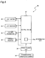
- Fig. 5 is a block diagram of the liquid sensor 30 of the present embodiment.
- the same components as in Figs. 1 to 3 are denoted by the same reference signs as in Figs. 1 to 3 .
- the liquid sensor 30 of the present embodiment includes a wireless transmitter 35 that wirelessly transmits a signal to the external apparatus, a wireless receiver 36 that wirelessly receives a signal from the external apparatus, and a control device 37.
- the wireless transmitter 35 can communicate with the controller 13 (shown in Fig. 1 ) of the hydraulic unit 1, and transmits an electric signal output from the light receiver 33 to the controller 13 of the hydraulic unit 1.
- the wireless receiver 36 can communicate with the controller 13 of the hydraulic unit 1, and receives an electric signal such as a control signal from the controller 13 of the hydraulic unit 1.
- the control device 37 controls the light emitter 32, the light receiver 33, the wireless transmitter 35, and the wireless receiver 36.
- the control device 37 of the present embodiment includes a determination unit 37a that determines the degree of deterioration of the liquid (hydraulic oil in the present embodiment) using the detection values output from the light receiver 33. Specifically, the determination unit 37a determines the degree of deterioration of the hydraulic oil using the red detection value R, the green detection value G, and the blue detection value B output from the light receiver 33.
- the liquid sensor 30 further includes a power source unit 38 for supplying power (see a two-dot chain line in Fig. 5 ) to each of the light emitter 32, the light receiver 33, the wireless transmitter 35, the wireless receiver 36, and the control device 37.
- the power source unit 38 of the present embodiment includes a rechargeable battery.
- the power source unit 38 is electrically connected to the thermoelectric conversion element 34.
- the thermoelectric conversion element 34 generates electric power for charging the power source unit 38 using a temperature difference between the hydraulic oil tank 10 (shown in Fig. 1 ) and the air around the liquid sensor 30.
- the light emitter 32 of the liquid sensor 30 emits white light from the light emitting element using the power supplied from the power source unit 38.
- the light receiver 33 of the liquid sensor 30 receives detection light emitted from the light emitter 32 and having passed through the liquid level gauge main body 21 having translucency and the hydraulic oil in the liquid level gauge main body 21.
- the light receiver 33 outputs, to the determination unit 37a of the control device 37, the red detection value R, the green detection value G, and the blue detection value B respectively representing the amounts of light components having wavelengths of red, green, and blue included in the detection light received by the light receiving element of the light receiver 33.
- Fig. 6 is a diagram showing a relationship between the ASTM color of the hydraulic oil and the red detection value R, the green detection value G, and the blue detection value B in the present embodiment.
- Fig. 6 shows the red detection value R, the green detection value G, and the blue detection value B for the detection light that has transmitted through the hydraulic oil of each ASTM color.
- the vertical axis in Fig. 6 indicates a detection value [arbitrary scale] representing the amount of light output from the light receiver 33.
- the horizontal axis in Fig. 6 indicates the ASTM color indicating the hue of the hydraulic oil.
- the ASTM color is measured in accordance with ASTM D 1500.
- the hue of the hydraulic oil is numerically expressed from 0.5 of a light color to 8.0 of a dark color in increments of 0.5.
- the ASTM color is an index of the degree of deterioration of the hydraulic oil, and indicates that the greater the value of the ASTM color, the more the hydraulic oil is deteriorated.
- the amount of the detection light received by the light receiver 33 decreases, and thus, the detection value representing the amount of light also decreases monotonically.
- the red detection value R, the green detection value G, and the blue detection value B decrease monotonically.
- the amount of change in the red detection value R accompanying the change in the ASTM color is smaller than the amounts of change in the green detection value G and the blue detection value B accompanying the change in the ASTM color.
- the amount of change in the green detection value G accompanying the change in the ASTM color is larger than the amount of change in the red detection value R accompanying the change in the ASTM color, and is smaller than the amount of change in the blue detection value B accompanying the change in the ASTM color.
- the amount of change in the blue detection value B accompanying the change in the ASTM color is larger than the amounts of change in the red detection value R and the green detection value G accompanying the change in the ASTM color.
- the determination unit 37a determines the degree of deterioration of the hydraulic oil from a ratio B/R of the blue detection value B to the red detection value R and a ratio G/R of the green detection value G to the red detection value R.
- the red detection value R of the present embodiment is an example of a first detection value according to the present disclosure.
- the blue detection value B of the present embodiment is an example of a second detection value according to the present disclosure.
- the green detection value G of the present embodiment is an example of a third detection value according to the present disclosure.
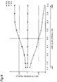
- Fig. 7 is a diagram showing a relationship between the ratios of the red detection value R, the green detection value G, and the blue detection value B to the red detection value R and the ASTM color of the hydraulic oil.
- the vertical axis in Fig. 7 indicates the ratio of each detection value to the red detection value R.
- the horizontal axis in Fig. 7 indicates the ASTM color indicating the hue of the hydraulic oil.
- a ratio R/R of the red detection value R to the red detection value R is indicated by a square mark.
- the ratio G/R of the green detection value G to the red detection value R is indicated by a circle mark.
- the ratio B/R of the blue detection value B to the red detection value R is indicated by a triangle mark.
- the ratio G/R of the green detection value G to the red detection value R decreases generally monotonically as the value of the ASTM color increases. In other words, the ratio G/R of the green detection value G to the red detection value R decreases generally monotonically as the degree of deterioration of the hydraulic oil progresses.
- the ratio B/R of the blue detection value B to the red detection value R decreases monotonically as the value of the ASTM color increases. In other words, the ratio B/R of the blue detection value B to the red detection value R decreases monotonically as the degree of deterioration of the hydraulic oil progresses.
- the amount of change in the ratio B/R of the blue detection value B to the red detection value R accompanying the change in the ASTM color is larger than the amount of change in the ratio G/R of the green detection value G to the red detection value R accompanying the change in the ASTM color.
- the determination unit 37a determines the degree of deterioration of the hydraulic oil based on the correspondence relationship shown in Fig. 7 between the ASTM color of the hydraulic oil (corresponding to the degree of deterioration of the hydraulic oil) and the ratio B/R of the blue detection value B to the red detection value R. Specifically, first, the determination unit 37a of the present embodiment calculates the ratio B/R of the blue detection value B to the red detection value R from the red detection value R and the blue detection value B output from the light receiver 33. Next, based on the correspondence relationship between the degree of deterioration of the hydraulic oil and the ratio B/R, the determination unit 37a determines the degree of deterioration of the hydraulic oil from the ratio B/R calculated from the detection values.
- the determination unit 37a of the present embodiment also determines the degree of deterioration of the hydraulic oil based on the ratio G/R of the green detection value G to the red detection value R.
- the determination unit 37a determines the degree of deterioration of the hydraulic oil based on the correspondence relationship shown in Fig. 7 between the degree of deterioration of the hydraulic oil and the ratio G/R of the green detection value G to the red detection value R.
- the determination unit 37a of the present embodiment calculates the ratio G/R of the green detection value G to the red detection value R from the red detection value R and the green detection value G output from the light receiver 33.
- the determination unit 37a determines the degree of deterioration of the hydraulic oil from the ratio G/R calculated from the detection value.
- the control device 37 controls the light emitter 32 to emit light to notify the user of the deterioration.
- the determination unit 37a determines that the hydraulic oil is deteriorated when the calculated ratio B/R of the blue detection value B to the red detection value R is smaller than a predetermined threshold ⁇ 1 (for example, the ratio B/R corresponding to the value of ASTM color of 4.0, see a two-dot chain line in the drawing).
- the determination unit 37a determines that the hydraulic oil is deteriorated when the calculated ratio G/R of the green detection value G to the red detection value R is smaller than a predetermined threshold ⁇ 1 (for example, the ratio G/R corresponding to the value of ASTM color of 4.0, see a two-dot chain line in the drawing).
- a predetermined threshold ⁇ 1 for example, the ratio G/R corresponding to the value of ASTM color of 4.0, see a two-dot chain line in the drawing.
- the determination unit 37a of the present embodiment determines that the hydraulic oil is deteriorated when the calculated ratio B/R of the blue detection value B to the red detection value R is smaller than the predetermined threshold ⁇ 1, or when the calculated ratio G/R of the green detection value G to the red detection value R is smaller than the predetermined threshold ⁇ 1.
- the controller 13 (shown in Fig. 1 ) of the hydraulic unit 1 may display a numerical value (for example, the ASTM color value) or color on a display unit 13a provided in the controller 13, a display unit (not shown) provided in the external apparatus to which the hydraulic unit 1 supplies the hydraulic oil, or others in accordance with the level of the degree of deterioration of the hydraulic oil. Thus, it is possible to alert the user to replace the hydraulic oil before the hydraulic oil needs to be replaced.
- the controller 13 (shown in Fig. 1 ) of the hydraulic unit 1 may notify the user of the deterioration of the hydraulic oil before the hydraulic oil needs to be replaced.
- the controller 13 of the hydraulic unit 1 may notify the user of the deterioration of the hydraulic oil by causing the light emitter 32 to emit light even before the ASTM color becomes dark to 4.0 or more, for example. In this case, as the deterioration of the hydraulic oil progresses, the frequency of light emission of the light emitter 32 may increase.
- the measurement using the liquid sensor 30 described above is preferably performed after it is determined that the hydraulic unit 1 is in a stable operation state by referring to the operation time or the oil temperature rise after the start of the hydraulic unit 1.
- Fig. 8 is a diagram showing a relationship between a color difference and the ASTM color according to a comparative example of the present embodiment.
- the vertical axis in Fig. 8 indicates the color difference [arbitrary scale].
- the horizontal axis in Fig. 8 indicates the ASTM color.
- the color difference is obtained from the difference between the red detection value R and the blue detection value B.
- the color difference R-B increases as the value of the ASTM color increases, and decreases beyond the extreme value.
- the degree of deterioration of the hydraulic oil may not be uniquely determined for one color difference R-B, and there is a risk that the determination unit 37a erroneously detects the degree of deterioration of the hydraulic oil.
- the determination unit 37a determines that the hydraulic oil is not deteriorated because the color difference R-B is smaller than the threshold ⁇ even when the value of the ASTM color is larger than 7.0.
- the ratio B/R of the blue detection value B to the red detection value R decreases monotonically as the degree of deterioration of the hydraulic oil progresses. In other words, only one degree of deterioration of the hydraulic oil is determined for one ratio B/R of the blue detection value B to the red detection value R. Therefore, according to the present embodiment, the determination unit 37a determines the degree of deterioration of the hydraulic oil at the time when the red detection value R and the blue detection value B are detected. As a result, the determination unit 37a does not need to determine the degree of deterioration of the hydraulic oil from the temporal change of the detection value, and does not need to continuously detect the detection value, so that the degree of deterioration of the hydraulic oil can be determined with a simple configuration.
- the determination unit 37a can be suppressed from erroneously determining the degree of deterioration of the hydraulic oil.
- the determination unit 37a of the present embodiment determines the degree of deterioration of the hydraulic oil based on the ratio B/R of the blue detection value B to the red detection value R and also on the ratio G/R of the green detection value G to the red detection value R. As a result, the determination accuracy can be improved as compared with the case where the degree of deterioration of the hydraulic oil is determined only by the ratio B/R of the blue detection value B to the red detection value R.
- the determination unit 37a determines that the hydraulic oil is deteriorated when the calculated ratio B/R of the blue detection value B to the red detection value R is smaller than the predetermined threshold ⁇ 1 or when the calculated ratio G/R of the green detection value G to the red detection value R is smaller than the predetermined threshold ⁇ 1, but the present invention is not limited thereto.
- the determination unit 37a may determine that the hydraulic oil is deteriorated when the calculated ratio B/R of the blue detection value B to the red detection value R is smaller than the predetermined threshold ⁇ 1 and also when the calculated ratio G/R of the green detection value G to the red detection value R is smaller than the predetermined threshold ⁇ 1.
- the determination unit 37a determines the degree of deterioration of the hydraulic oil based on the ratio B/R of the blue detection value B to the red detection value R and also on the ratio G/R of the green detection value G to the red detection value R, but the present invention is not limited thereto.
- the determination unit 37a may determine the degree of deterioration of the hydraulic oil only by the ratio B/R of the blue detection value B to the red detection value R, or may determine the degree of deterioration of the hydraulic oil only by the ratio G/R of the green detection value G to the red detection value R.
- the determination unit 37a determines the degree of deterioration of the hydraulic oil based on the ratio B/R of the blue detection value B to the red detection value R, but the present invention is not limited thereto.
- the determination unit 37a may use a ratio (B + c)/R or a ratio B/(R + c) to determine the degree of deterioration of the hydraulic oil.
- c is any number, and may be a constant or a variable. That is, the determination unit 37a may determine the degree of deterioration of the hydraulic oil based on a ratio that includes the ratio B/R.
- the ratio B/R of the blue detection value B to the red detection value R used by the determination unit 37a to determine the degree of deterioration of the hydraulic oil is not strictly limited to itself, but may include at least the ratio B/R, and may be appropriately modified within this range.
- the determination unit 37a determines the degree of deterioration of the hydraulic oil based on the ratio G/R of the green detection value G to the red detection value R, but the present invention is not limited thereto.
- the determination unit 37a may use a ratio (G + c)/R or a ratio G/(R + c) to determine the degree of deterioration of the hydraulic oil.
- c is any number, and may be a constant or a variable. That is, the determination unit 37a may determine the degree of deterioration of the hydraulic oil based on a ratio that includes the ratio G/R.
- the ratio G/R of the green detection value G to the red detection value R used by the determination unit 37a to determine the degree of deterioration of the hydraulic oil is not strictly limited to itself, but may include at least the ratio G/R, and may be appropriately modified within this range.
- a hydraulic unit 1 of a second embodiment has the same configuration as the hydraulic unit 1 of the first embodiment except for the first color, the second color, and the third color, and the first detection value, the second detection value, and the third detection value, and the description of the first embodiment referring to Figs. 1 to 6 is applied to the second embodiment.
- a determination unit 37a of the present embodiment determines the degree of deterioration of the hydraulic oil from a ratio B/G of the blue detection value B to the green detection value G and a ratio R/G of the red detection value R to the green detection value G.
- the green of the present embodiment is an example of the first color according to the present disclosure
- the green detection value G of the present embodiment is an example of the first detection value according to the present disclosure.
- the blue of the present embodiment is an example of the second color according to the present disclosure
- the blue detection value B in the present embodiment is an example of the second detection value according to the present disclosure.
- the green of the present embodiment is an example of the third color according to the present disclosure
- the green detection value G of the present embodiment is an example of the third detection value according to the present disclosure.
- Fig. 9 is a diagram showing a relationship between the ratios of the red detection value R, the green detection value G, and the blue detection value B to the green detection value G and the ASTM color of the hydraulic oil.
- the vertical axis in Fig. 9 indicates the ratio of each detection value to the green detection value G.
- the horizontal axis in Fig. 9 indicates the ASTM color indicating the hue of the hydraulic oil.
- the ratio R/G of the red detection value R to the green detection value G is indicated by a square mark.
- a ratio G/G of the green detection value G to the green detection value G is indicated by a circle mark.
- the ratio B/G of the blue detection value B to the green detection value G is indicated by a triangle mark.
- the ratio R/G of the red detection value R to the green detection value G increases generally monotonically as the value of the ASTM color increases. In other words, the ratio R/G of the red detection value R to the green detection value G increases generally monotonically as the degree of deterioration of the hydraulic oil progresses.
- the ratio B/G of the blue detection value B to the green detection value G decreases monotonically as the value of the ASTM color increases. In other words, the ratio B/G of the blue detection value B to the green detection value G decreases monotonically as the degree of deterioration of the hydraulic oil progresses.
- the amount of change in the ratio B/G of the blue detection value B to the green detection value G accompanying the change in the ASTM color is larger than the amount of change in the ratio R/G of the red detection value R to the green detection value G accompanying the change in the ASTM color.
- the determination unit 37a determines the degree of deterioration of the hydraulic oil based on the correspondence relationship shown in Fig. 9 between the degree of deterioration of the hydraulic oil and the ratio B/G of the blue detection value B to the green detection unit G. Specifically, first, the determination unit 37a of the present embodiment calculates the ratio B/G of the blue detection value B to the green detection value G from the green detection value G and the blue detection value B output from a light receiver 33. Next, based on the correspondence relationship between the degree of deterioration of the hydraulic oil and the ratio B/G, the determination unit 37a determines the degree of deterioration of the hydraulic oil from the ratio B/G calculated from the detection values.
- the determination unit 37a of the present embodiment determines the degree of deterioration of the hydraulic oil based on the ratio R/G of the red detection value R to the green detection value G.
- the determination unit 37a determines the degree of deterioration of the hydraulic oil based on the correspondence relationship shown in Fig. 9 between the degree of deterioration of the hydraulic oil and the ratio R/G of the red detection value R to the green detection value G. Specifically, first, the determination unit 37a of the present embodiment calculates the ratio R/G of the red detection value R to the green detection value G from the green detection value G and the red detection value R output from the light receiver 33. Next, based on the correspondence relationship between the degree of deterioration of the hydraulic oil and the ratio R/G, the determination unit 37a determines the degree of deterioration of the hydraulic oil from the calculated ratio R/G.
- the control device 37 controls the light emitter 32 to emit light to notify the user of the deterioration.
- the determination unit 37a determines that the hydraulic oil is deteriorated when the calculated ratio B/G of the blue detection value B to the green detection value G is smaller than a predetermined threshold ⁇ 2 (for example, the ratio B/G corresponding to the value of ASTM color of 4.0, see a two-dot chain line in the drawing).
- the determination unit 37a determines that the hydraulic oil is deteriorated when the calculated ratio R/G of the red detection value R to the green detection value G is larger than a predetermined threshold ⁇ 2 (for example, the ratio R/G corresponding to the value of ASTM color of 4.0, see a two-dot chain line in the drawing).
- a predetermined threshold ⁇ 2 for example, the ratio R/G corresponding to the value of ASTM color of 4.0, see a two-dot chain line in the drawing.
- the determination unit 37a of the present embodiment determines that the hydraulic oil is deteriorated when the calculated ratio B/G of the blue detection value B to the green detection unit G is smaller than the predetermined threshold ⁇ 2 or when the calculated ratio R/G of the red detection value R to the green detection unit G is larger than the predetermined threshold ⁇ 2.
- the second embodiment exhibits operational effects similar to those of the first embodiment.
- the determination unit 37a determines that the hydraulic oil is deteriorated when the calculated ratio B/G of the blue detection value B to the green detection unit G is smaller than the predetermined threshold ⁇ 2 or when the calculated ratio R/G of the red detection value R to the green detection unit G is larger than the predetermined threshold ⁇ 2, but the present invention is not limited thereto.
- the determination unit 37a may determine that the hydraulic oil is deteriorated when the calculated ratio B/G of the blue detection value B to the green detection unit G is smaller than a predetermined threshold ⁇ 2 and also when the calculated ratio R/G of the red detection value R to the green detection unit G is larger than the predetermined threshold ⁇ 2.
- the determination unit 37a determines the degree of deterioration of the hydraulic oil based on the ratio B/G of the blue detection value B to the green detection value G and also on the ratio R/G of the red detection value R to the green detection value G, but the present invention is not limited thereto.
- the determination unit 37a may determine the degree of deterioration of the hydraulic oil only by the ratio B/G of the blue detection value B to the green detection value G, or may determine the degree of deterioration of the hydraulic oil only by the ratio R/G of the red detection value R to the green detection value G.
- the determination unit 37a determines the degree of deterioration of the hydraulic oil based on the ratio B/G of the blue detection value B to the green detection value G, but the present invention is not limited thereto.
- the determination unit 37a may use a ratio (B + c)/G or a ratio B/(G + c) to determine the degree of deterioration of the hydraulic oil.
- c is any number, and may be a constant or a variable. That is, the determination unit 37a may determine the degree of deterioration of the hydraulic oil based on a ratio that includes the ratio B/G.
- the ratio B/G of the blue detection value B to the green detection value G used by the determination unit 37a to determine the degree of deterioration of the hydraulic oil is not strictly limited to itself, but may include at least the ratio B/G, and may be appropriately modified within this range.
- the determination unit 37a determines the degree of deterioration of the hydraulic oil based on the ratio R/G of the red detection value R to the green detection value G, but the present invention is not limited thereto.
- the determination unit 37a may use a ratio (R + c)/G or a ratio R/(G + c) to determine the degree of deterioration of the hydraulic oil.
- c is any number, and may be a constant or a variable. That is, the determination unit 37a may determine the degree of deterioration of the hydraulic oil based on a ratio that includes the ratio R/G.
- the ratio R/G of the red detection value R to the green detection value G used by the determination unit 37a to determine the degree of deterioration of the hydraulic oil is not strictly limited to itself, but may include at least the ratio R/G, and may be appropriately modified within this range.
- a hydraulic unit 1 of a third embodiment has the same configuration as the hydraulic unit 1 of the first embodiment except for the first color, the second color, and the third color, and the first detection value, the second detection value, and the third detection value, and the description or the first embodiment referring to Figs. 1 to 6 is applied to the third embodiment.
- a determination unit 37a of the present embodiment determines the degree of deterioration of the hydraulic oil from a ratio R/B of the red detection value R to the blue detection value B and a ratio G/B of the green detection value G to the blue detection value B.
- the blue in the present embodiment is an example of the first color according to the present disclosure
- the blue detection value B in the present embodiment is an example of the first detection value according to the present disclosure.
- the red in the present embodiment is an example of the second color according to the present disclosure
- the red detection value R in the present embodiment is an example of the second detection value according to the present disclosure.
- the green of the present embodiment is an example of the third color according to the present disclosure
- the green detection value G is an example of the third detection value according to the present disclosure.
- Fig. 10 is a diagram showing a relationship between the ratios of the red detection value R, the green detection value G, and the blue detection value B to the blue detection value B and the ASTM color of the hydraulic oil.
- the vertical axis in Fig. 10 indicates the ratio of each detection value to the blue detection value B.
- the horizontal axis in Fig. 10 indicates the ASTM color indicating the hue of the hydraulic oil.
- the ratio R/B of red detection value R to blue detection value B is indicated by a square mark.
- the ratio G/B of the blue detection value B to the blue detection value B is indicated by a circle mark.
- a ratio B/B of the blue detection value B to the blue detection value B is indicated by a triangle mark.
- the ratio R/B of the red detection value R to the blue detection value B increases generally monotonically as the value of the ASTM color increases. In other words, the ratio R/B of the red detection value R to the blue detection value B increases monotonically as the degree of deterioration of the hydraulic oil progresses. Similarly, the ratio G/B of the green detection value G to the blue detection value B increases monotonically as the value of the ASTM color increases. In other words, the ratio G/B of the green detection value G to the blue detection value B increases monotonically as the degree of deterioration of the hydraulic oil progresses.
- the amount of change in the ratio R/B of the red detection value R to the blue detection value B accompanying the change in the ASTM color is larger than the amount of change in the ratio G/B of the green detection value G to the blue detection value B accompanying the change in the ASTM color.
- the determination unit 37a determines the degree of deterioration of the hydraulic oil based on the correspondence relationship shown in Fig. 10 between the degree of deterioration of the hydraulic oil and the ratio R/B of the red detection value R to the blue detection value B. Specifically, first, the determination unit 37a of the present embodiment calculates the ratio R/B of the red detection value R to the blue detection value B from the blue detection value B and the red detection value R output from a light receiver 33. Next, based on the correspondence relationship between the degree of deterioration of the hydraulic oil and the ratio R/B, the determination unit 37a determines the degree of deterioration of the hydraulic oil from the calculated ratio R/B.
- the determination unit 37a of the present embodiment determines the degree of deterioration of the hydraulic oil based on the ratio G/B of the green detection value G to the blue detection value B.
- the determination unit 37a determines the degree of deterioration of the hydraulic oil based on the correspondence relationship shown in Fig. 10 between the degree of deterioration of the hydraulic oil and the ratio G/B of the green detection value G to the blue detection value B. Specifically, first, the determination unit 37a of the present embodiment calculates the ratio G/B of the green detection value G to the blue detection value B from the blue detection value B and the green detection value G output from the light receiver 33. Next, based on the correspondence relationship between the degree of deterioration of the hydraulic oil and the ratio G/B, the determination unit 37a determines the degree of deterioration of the hydraulic oil from the calculated ratio G/B.
- the control device 37 controls the light emitter 32 to emit light to notify the user of the deterioration.
- the determination unit 37a determines that the hydraulic oil is deteriorated when the calculated ratio R/B of the red detection value R to the blue detection value B is larger than a predetermined threshold ⁇ 3 (for example, the ratio R/B corresponding to the value of ASTM color of 4.0, see a two-dot chain line in the drawing).
- the determination unit 37a determines that the hydraulic oil is deteriorated when the calculated ratio G/B of the green detection value G to the blue detection value B is larger than a predetermined threshold ⁇ 3 (for example, the ratio G/B corresponding to the value of ASTM color of 4.0, see a two-dot chain line in the drawing).
- a predetermined threshold ⁇ 3 for example, the ratio G/B corresponding to the value of ASTM color of 4.0, see a two-dot chain line in the drawing.
- the determination unit 37a of the present embodiment determines that the hydraulic oil is deteriorated when the calculated ratio R/B of the red detection value R to the blue detection value B is larger than the predetermined threshold ⁇ 3, or when the calculated ratio G/B of the green detection value G to the blue detection value B is larger than the predetermined threshold ⁇ 3.
- the third embodiment exhibits operational effects similar to those of the first embodiment.
- the determination unit 37a determines that the hydraulic oil is deteriorated when the calculated ratio R/B of the red detection value R to the blue detection value B is larger than the predetermined threshold ⁇ 3 or when the calculated ratio G/B of the green detection value G to the blue detection value B is larger than the predetermined threshold ⁇ 3, but the present invention is not limited thereto.
- the determination unit 37a may determine that the hydraulic oil is deteriorated when the calculated ratio R/B of the red detection value R to the blue detection value B is larger than the predetermined threshold ⁇ 3 and also when the calculated ratio G/B of the green detection value G to the blue detection value B is larger than the predetermined threshold ⁇ 3.
- the determination unit 37a determines the degree of deterioration of the hydraulic oil based on the ratio R/B of the red detection value R to the blue detection value B and also on the ratio G/B of the green detection value G to the blue detection value B, but the present invention is not limited thereto.
- the determination unit 37a may determine the degree of deterioration of the hydraulic oil only by the ratio R/B of the red detection value R to the blue detection value B, or may determine the degree of deterioration of the hydraulic oil only by the ratio G/B of the green detection value G to the blue detection value B.
- the determination unit 37a determines the degree of deterioration of the hydraulic oil based on the ratio R/B of the red detection value R to the blue detection value B, but the present invention is not limited thereto.
- the determination unit 37a may use a ratio (R + c)/B or a ratio R/(B + c) to determine the degree of deterioration of the hydraulic oil.
- c is any number, and may be a constant or a variable. That is, the determination unit 37a may determine the degree of deterioration of the hydraulic oil based on a ratio that includes the ratio R/B.
- the ratio R/B of the red detection value R to the blue detection value B used by the determination unit 37a to determine the degree of deterioration of the hydraulic oil is not strictly limited to itself, but may include at least the ratio R/B, and may be appropriately modified within this range.
- the determination unit 37a determines the degree of deterioration of the hydraulic oil based on the ratio G/B of the green detection value G to the blue detection value B, but the present invention is not limited thereto.
- the determination unit 37a may use a ratio (G + c)/B or a ratio G/(B + c) to determine the degree of deterioration of the hydraulic oil.
- c is any number, and may be a constant or a variable. That is, the determination unit 37a may determine the degree of deterioration of the hydraulic oil based on a ratio that includes the ratio G/B.
- the ratio G/B of the green detection value G to the blue detection value B used by the determination unit 37a to determine the degree of deterioration of the hydraulic oil is not strictly limited to itself, but may include at least the ratio G/B, and may be appropriately modified within this range.
- a liquid sensor 30 of a fourth embodiment has the same configuration as the liquid sensor 30 of the first embodiment except for not including a light emitter 32, and a detailed description thereof is omitted.
- Fig. 11 is a schematic diagram showing a state in which a hydraulic unit 1 according to the present embodiment is installed in a factory.
- a light receiver 33 of the present embodiment may receive light, for example, formed after light L1 of a fluorescent lamp F in the factory in which the hydraulic unit 1 is installed passed through the hydraulic oil introduced into a liquid level gauge 20.
- the light receiver 33 of the present embodiment may receive light, for example, formed after light L2 shining into the factory through a window W of the factory in which the hydraulic unit 1 is installed passed through the hydraulic oil introduced into the liquid level gauge 20.
- the liquid sensor 30 is preferably configured such that the casing 31 has translucency, or configured in an L shape by eliminating a portion facing the light receiver 33.
- the fourth embodiment exhibits operational effects similar to those of the first embodiment.
- the configuration of the liquid sensor 30 can be simplified.
- a liquid sensor 130 of the fifth embodiment has the same configuration as the liquid sensor 30 of the first embodiment except for being a reflective sensor, and detailed description of the same configuration is omitted.
- Fig. 12 is a schematic front view showing a liquid level gauge 20 and the liquid sensor 130 according to the present embodiment.
- the liquid sensor 130 of the present embodiment is a reflective color sensor. As shown in Fig. 12 , the liquid sensor 130 of the present embodiment includes a casing 131, a light emitter 32 that emits light, and a light receiver 33 that receives the light emitted from the light emitter 32, passing through a liquid level gauge main body 21 having translucency, and reflected by the hydraulic oil in the liquid level gauge main body 21. In the present embodiment, the light emitter 32 and the light receiver 33 are disposed on the same side with respect to the liquid level gauge main body 21.
- the fifth embodiment exhibits operational effects similar to those of the first embodiment.
- the liquid sensor 130 since the light emitter 32 and the light receiver 33 are arranged on the same side with respect to the liquid level gauge main body 21, the liquid sensor 130 can be miniaturized as compared with a case where the light emitter and the light receiver are arranged across the liquid level gauge main body 21.
- liquid sensor 130 is the reflective sensor, it is not necessary to adjust the optical axis of the light emitter 32 and the optical axis of the light receiver 33, and it is possible to easily attach the liquid sensor 130 to the liquid level gauge 20.
- the liquid sensor 30 determines the degree of deterioration of the hydraulic oil of the hydraulic unit 1, but the present invention is not limited thereto, and the degree of deterioration of another liquid such as cutting liquid or coolant may be determined. In addition, the liquid sensor 30 may determine a state in which another liquid is mixed in the hydraulic oil.
- first to fifth embodiments may be appropriately combined and used.
- the first color, the second color, and the third color according to the present disclosure are any one of red, green, and blue, but the colors are not limited thereto, and may be other colors such as yellow or purple. That is, in the first to fifth embodiments, a combination of red, green, and blue is used as the combination of the first to third colors according to the present disclosure, but the combination is not limited thereto, and for example, a combination of magenta, yellow, and cyan may be used.
- the liquid level gauge 20 being an example of the accommodation unit of the present disclosure includes the liquid level gauge main body 21 having a substantially rectangular parallelepiped shape, but the present invention is not limited thereto.
- the liquid level gauge 20 being an example of the accommodation unit of the present disclosure may include a liquid level gauge main body in which a cross-sectional shape in a cross section orthogonal to the longitudinal direction is a semicircular shape.
Landscapes
- Chemical & Material Sciences (AREA)
- Physics & Mathematics (AREA)
- Health & Medical Sciences (AREA)
- Life Sciences & Earth Sciences (AREA)
- Analytical Chemistry (AREA)
- Immunology (AREA)
- Pathology (AREA)
- General Physics & Mathematics (AREA)
- General Health & Medical Sciences (AREA)
- Biochemistry (AREA)
- Engineering & Computer Science (AREA)
- Spectroscopy & Molecular Physics (AREA)
- Chemical Kinetics & Catalysis (AREA)
- Medicinal Chemistry (AREA)
- Food Science & Technology (AREA)
- Oil, Petroleum & Natural Gas (AREA)
- General Chemical & Material Sciences (AREA)
- General Engineering & Computer Science (AREA)
- Mechanical Engineering (AREA)
- Investigating Or Analysing Materials By Optical Means (AREA)
Abstract
Description
- The present disclosure relates to liquid deterioration determination devices and hydraulic units.
- A conventional liquid deterioration determination device includes a light emitting element that emits detection light to lubricant, and a light receiving element that acquires a detection value representing color information of the detection light transmitted through the lubricant (see Patent Literature 1). This liquid deterioration determination device includes a determination unit that calculates brightness or a color component maximum difference from the detection value and determines deterioration of lubricant from a temporal change of the brightness or the color component maximum difference.
- Patent Literature 1:
WO 2015/060457 A - However, in the conventional liquid deterioration determination device, because the deterioration of the lubricant is determined from the temporal change of the brightness or the maximum color difference, the lightness or the maximum color difference needs to be continuously recorded, and there is a problem that a configuration of the determination unit becomes complicated.
- The present disclosure proposes a liquid deterioration determination device that can determine deterioration of a liquid with a simple configuration.
- A liquid deterioration determination device according to an aspect of the present disclosure includes a light receiver configured to receive detection light transmitted through a liquid or detection light reflected by the liquid and a determination unit configured to determine a degree of deterioration of the liquid. The light receiver is configured to output a first detection value representing an amount of a light component of a first color included in the detection light transmitted through the liquid or the detection light reflected by the liquid and a second detection value representing an amount of a light component of a second color different from the first color and included in the detection light transmitted through the liquid or the detection light reflected by the liquid. The determination unit determines the degree of deterioration of the liquid based on a ratio of the second detection value to the first detection value.
- According to the present disclosure, the degree of deterioration of the liquid can be determined with a simple configuration without continuously detecting the detection value representing the amount of the detection light transmitted through the liquid or the detection light reflected by the liquid.
- The liquid deterioration determination device according to one embodiment includes a light emitter configured to emit the detection light to the liquid. The light receiver is configured to receive the detection light emitted from the light emitter and transmitted through the liquid or reflected by the liquid.
- In the liquid deterioration determination device according to the one embodiment, the light receiver is configured to output a third detection value representing an amount of a light component of a third color different from the first color and the second color and included in the detection light transmitted through the liquid or the detection light reflected by the liquid. The determination unit determines the degree of deterioration of the liquid based on both the ratio of the second detection value to the first detection value and a ratio of the third detection value to the first detection value.
- In the liquid deterioration determination device of the one embodiment, each of the first color, the second color, and the third color is any one of red, green, and blue.
- In the liquid deterioration determination device of the one embodiment, the first color is red.
- Another aspect of the present disclosure provides a hydraulic unit having the above-described liquid deterioration determination device.
-
-
Fig. 1 is a perspective view of a hydraulic unit according to a first embodiment of the present disclosure. -
Fig. 2 is a front view of a liquid sensor according to the first embodiment. -
Fig. 3 is a cross-sectional view taken along a line III-III inFig. 2 . -
Fig. 4 is a cross-sectional view taken along a line IV-IV inFig. 3 . -
Fig. 5 is a block diagram of the liquid sensor according to the first embodiment. -
Fig. 6 is a diagram showing a relationship between a detection value detected by the liquid sensor according to the first embodiment and the ASTM color of hydraulic oil. -
Fig. 7 is a diagram showing a relationship between a ratio of the detection value detected by the liquid sensor according to the first embodiment and the ASTM color of hydraulic oil. -
Fig. 8 is a diagram showing a relationship between a color difference and the ASTM color according to a comparative example of the first embodiment. -
Fig. 9 is a diagram showing a relationship between a ratio of a detection value detected by a liquid sensor according to a second embodiment of the present disclosure and the ASTM color of hydraulic oil. -
Fig. 10 is a diagram showing a relationship between a ratio of a detection value detected by a liquid sensor according to a third embodiment of the present disclosure and the ASTM color of hydraulic oil. -
Fig. 11 is a schematic perspective view of a hydraulic unit according to a fourth embodiment of the present disclosure. -
Fig. 12 is a front view of a liquid sensor according to a sixth embodiment of the present disclosure. - Hereinafter, liquid sensors and hydraulic units according to embodiments of the present disclosure will be described with reference to the accompanying drawings.
-
Fig. 1 is a perspective view of ahydraulic unit 1 according to a first embodiment of the present disclosure. Thehydraulic unit 1 according to the present embodiment supplies hydraulic oil to an external apparatus such as a machining tool. - Referring to
Fig. 1 , thehydraulic unit 1 includes ahydraulic oil tank 10 that accommodates hydraulic oil, and amount 11 attached to an upper part of thehydraulic oil tank 10. Thehydraulic unit 1 includes a hydraulic pump (not shown), a motor (not shown) that drives the hydraulic pump, anoil cooler 12 that cools hydraulic oil discharged from the hydraulic pump, and acontroller 13 that controls the motor. The hydraulic pump, the motor, theoil cooler 12, and thecontroller 13 are mounted on themount 11, and thehydraulic oil tank 10 is disposed below themount 11. In addition, thehydraulic unit 1 includes acooling fan 14 that supplies cooling air to the motor and theoil cooler 12. Thehydraulic unit 1 is herein described by way of example only; and not limited to the above-described structure. - A
liquid level gauge 20 for externally checking the amount of hydraulic oil accommodated in thehydraulic oil tank 10 is attached to ametal side surface 10a of thehydraulic oil tank 10. Since theliquid level gauge 20 is attached to theside surface 10a of thehydraulic oil tank 10, a user can easily visually check the amount of hydraulic oil accommodated in thehydraulic oil tank 10. In addition, aliquid sensor 30 that determines the degree of deterioration of liquid (hydraulic oil in the present embodiment) is attached to an outside of theliquid level gauge 20. Theliquid sensor 30 according to the present embodiment is an example of a liquid deterioration determination device according to the present disclosure. -
Fig. 2 is a schematic front view showing theliquid level gauge 20 and theliquid sensor 30 according to the present embodiment. Fif. 3 is a schematic cross-sectional view taken along a line III-III inFig. 2 . InFig. 3 , illustration of a detailed structure of the inside of theliquid sensor 30 is omitted. InFigs. 2 and3 , the same constituent elements as inFig. 1 are denoted by the same reference signs as inFig. 1 . - Referring to
Figs. 2 and3 , theliquid level gauge 20 of the present embodiment is an oil level gauge for checking the oil level of the hydraulic oil accommodated in thehydraulic oil tank 10. Theliquid level gauge 20 of the present embodiment includes a liquid level gaugemain body 21 made of a transparent acrylic resin and twobolts main body 21 to thehydraulic oil tank 10. Theliquid level gauge 20 according to the present embodiment is an example of a translucent tubular member into which the liquid (hydraulic oil in the present embodiment) according to the present disclosure is introduced. - The liquid level gauge
main body 21 of the present embodiment has a substantially rectangular parallelepiped shape, and is attached to thehydraulic oil tank 10 such that the liquid level gaugemain body 21 has a longitudinal direction that extends along the vertical direction. The liquid level gaugemain body 21 is hollow. Specifically, the liquid level gaugemain body 21 includes ahollow portion 21a being a space extending in the longitudinal direction inside the liquid level gaugemain body 21. The hydraulic oil is introduced into thehollow portion 21a of the liquid level gaugemain body 21 according to the amount of hydraulic oil stored in thehydraulic oil tank 10. The user can check the amount of hydraulic oil accommodated in thehydraulic oil tank 10 by visually observing the oil level of the hydraulic oil in thehollow portion 21a of the liquid level gaugemain body 21. The liquid level gaugemain body 21 is provided with an upper limit line HL indicating the upper limit of an allowable range of the oil level of the hydraulic oil and a lower limit line LL indicating the lower limit of the allowable range of the oil level of the hydraulic oil. - The
bolts Fig. 3 , each of thebolts tip portion 22a toward ahead portion 22b of the bolt. Thecommunication portion 22c is open in the radial direction at an axial end portions on thehead portion 22b side of each of thebolts bolts communication portions 22c of thebolts hydraulic oil tank 10 to thehollow portion 21a of the liquid level gaugemain body 21 in a state where thebolts main body 21 to thehydraulic oil tank 10. In other words, the internal space of thehydraulic oil tank 10, thehollow portion 21a of the liquid level gaugemain body 21, and thecommunication portions 22c of thebolts - In the state shown in
Fig. 3 , thecommunication portion 22c of thebolt 22B opens at thetip portion 22a into an area where the hydraulic oil accumulated in thehydraulic oil tank 10 exits. At this time, the hydraulic oil is introduced from thehydraulic oil tank 10 into thehollow portion 21a of the liquid level gaugemain body 21 through thecommunication portion 22c of thebolt 22B. In addition, thecommunication portion 22c of thebolt 22B is filled with the hydraulic oil. - As shown in
Fig. 3 , the oil level of the hydraulic oil introduced into the liquid level gaugemain body 21 coincides with the oil level of the hydraulic oil accommodated in thehydraulic oil tank 10. Thus, the user can check the amount of hydraulic oil accommodated in thehydraulic oil tank 10 by visually observing the oil level of the hydraulic oil introduced into thehollow portion 21a of the liquid level gaugemain body 21. - The
liquid sensor 30 of the present embodiment is a sensor for detecting the degree of deterioration of the hydraulic oil accommodated in thehydraulic oil tank 10. More specifically, theliquid sensor 30 is a transmissive color sensor. As shown inFig. 2 , theliquid sensor 30 of the present embodiment includes aU-shaped casing 31, alight emitter 32 that emits detection light, and alight receiver 33 that receives the detection light emitted from thelight emitter 32. Thelight emitter 32 and thelight receiver 33 are provided integrally with thecasing 31 so as to face each other. Specifically, thelight emitter 32 and thelight receiver 33 are provided integrally with thecasing 31 in a manner that the optical axis of thelight emitter 32 and the optical axis of thelight receiver 33 coincide with each other. - The
liquid sensor 30 is attached to the liquid level gaugemain body 21 such that thelight emitter 32 and thelight receiver 33 face each other across the liquid level gaugemain body 21. In addition, theliquid sensor 30 is attached to theliquid level gauge 20 such that height positions of thelight emitter 32 and thelight receiver 33 overlap with a height position of the lower limit line LL of the liquid level gaugemain body 21. - A packing (not shown) is provided between the casing 31 of the
liquid sensor 30 and the liquid level gaugemain body 21 of the present embodiment. This packing makes thecasing 31 and the liquid level gaugemain body 21 water-resistant and dustresistant, prevents external light from entering the liquid level gaugemain body 21, and brings the casing into close contact with the liquid gaugemain body 21 so that thecasing 31 is held by the liquid level gaugemain body 21. - The
light emitter 32 of the present embodiment includes a light emitting element for emitting detection light and a drive circuit for driving the light emitting element. The light emitting element of the present embodiment is a white light emitting diode. In other words, thelight emitter 32 of the present embodiment emits white detection light. - The
light receiver 33 of the present embodiment includes a light receiving element that converts the amount of light into an electric signal, an amplifier circuit that amplifies the electric signal output from the light receiving element, and an A/D conversion circuit that converts the analog electric signal amplified by the amplifier circuit into a digital electric signal. The light receiving element of the present embodiment is an RGB color sensor, and can detect the electric signal converted from received visible light separately for each of red, green, and blue. The red in the present embodiment is an example of a first color according to the present disclosure. The blue in the present embodiment is an example of a second color according to the present disclosure. The green in the present embodiment is an example of a third color according to the present disclosure. - The
light receiver 33 outputs a detection value representing the amount of a light component having a wavelength of each of red, green, and blue, for light having wavelengths not absorbed by the hydraulic oil in theliquid level gauge 20 among the detection light emitted from thelight emitter 32. In other words, thelight receiver 33 outputs a red detection value R, a green detection value G, and a blue detection value B representing the amounts of light components having different wavelengths from each other and included in the detection light transmitted through the hydraulic oil in theliquid level gauge 20. Specifically, the red detection value R in the present embodiment represents the amount of light of a red wavelength included in the detection light transmitted through the hydraulic oil in theliquid level gauge 20. The green detection value G in the present embodiment represents the amount of light of a green wavelength included in the detection light transmitted through the hydraulic oil in theliquid level gauge 20. Further, the blue detection value B in the present embodiment represents the amount of light of a blue wavelength included in the detection light transmitted through the hydraulic oil in theliquid level gauge 20. - The detection value indicating the amount of light is output as, for example, an output voltage or an output current from the
light receiver 33. Specifically, the red detection value R of the present embodiment is output as an output voltage or an output current from thelight receiver 33 for the red included in the detection light transmitted through the hydraulic oil in theliquid level gauge 20. The green detection value G of the present embodiment is output as an output voltage or an output current from thelight receiver 33 for the blue included in the detection light transmitted through the hydraulic oil in theliquid level gauge 20. The blue detection value B of the present embodiment is output as an output voltage or an output current from thelight receiver 33 for the green included in the detection light transmitted through the hydraulic oil in theliquid level gauge 20. - As shown in
Fig. 3 , theliquid sensor 30 of the present embodiment further includes athermoelectric conversion element 34 that converts heat into electric power. Thethermoelectric conversion element 34 of the present embodiment is provided so as to be in contact with theside surface 10a of thehydraulic oil tank 10. Theside surface 10a of thehydraulic oil tank 10 is likely to have a high temperature because the hydraulic oil accommodated in thehydraulic oil tank 10 has a high temperature due to heat generation from a sliding portion of the machining tool or the like. Thethermoelectric conversion element 34 generates power using a temperature difference between the temperature of theside surface 10a of thehydraulic oil tank 10 and the temperature of the air around theliquid sensor 30. -
Fig. 4 is a schematic cross-sectional view taken along a line IV-IV inFig. 3 . InFig. 4 , illustration of a detailed structure of the inside of theliquid sensor 30 is omitted. InFig. 4 , the same components as inFigs. 1 to 3 are denoted by the same reference signs as inFigs. 1 to 3 . - Referring to
Fig. 4 , thehollow portion 21a of the liquid level gaugemain body 21 has a circular cross-sectional shape in the cross section shown inFig. 4 . - As shown in
Fig. 4 , an optical axis X1 of thelight emitter 32 and an optical axis X2 of thelight receiver 33 coincide with each other. In addition, the optical axis X1 of thelight emitter 32 and the optical axis X2 of thelight receiver 33 extend to pass through the center C of thehollow portion 21a of the liquid level gaugemain body 21. Here, the optical axis X1 of thelight emitter 32 and the optical axis X2 of thelight receiver 33 do not necessarily need to pass through the center C of thehollow portion 21a. It is preferable that the shortest distance from the optical axis X1 of thelight emitter 32 and the optical axis X2 of thelight receiver 33 to the center C of thehollow portion 21a is 5 mm or less. -
Fig. 5 is a block diagram of theliquid sensor 30 of the present embodiment. InFig. 5 , the same components as inFigs. 1 to 3 are denoted by the same reference signs as inFigs. 1 to 3 . - Referring to
Fig. 5 , theliquid sensor 30 of the present embodiment includes awireless transmitter 35 that wirelessly transmits a signal to the external apparatus, awireless receiver 36 that wirelessly receives a signal from the external apparatus, and acontrol device 37. - The
wireless transmitter 35 can communicate with the controller 13 (shown inFig. 1 ) of thehydraulic unit 1, and transmits an electric signal output from thelight receiver 33 to thecontroller 13 of thehydraulic unit 1. Thewireless receiver 36 can communicate with thecontroller 13 of thehydraulic unit 1, and receives an electric signal such as a control signal from thecontroller 13 of thehydraulic unit 1. - The
control device 37 controls thelight emitter 32, thelight receiver 33, thewireless transmitter 35, and thewireless receiver 36. Thecontrol device 37 of the present embodiment includes adetermination unit 37a that determines the degree of deterioration of the liquid (hydraulic oil in the present embodiment) using the detection values output from thelight receiver 33. Specifically, thedetermination unit 37a determines the degree of deterioration of the hydraulic oil using the red detection value R, the green detection value G, and the blue detection value B output from thelight receiver 33. - The
liquid sensor 30 further includes apower source unit 38 for supplying power (see a two-dot chain line inFig. 5 ) to each of thelight emitter 32, thelight receiver 33, thewireless transmitter 35, thewireless receiver 36, and thecontrol device 37. Thepower source unit 38 of the present embodiment includes a rechargeable battery. In addition, thepower source unit 38 is electrically connected to thethermoelectric conversion element 34. Thethermoelectric conversion element 34 generates electric power for charging thepower source unit 38 using a temperature difference between the hydraulic oil tank 10 (shown inFig. 1 ) and the air around theliquid sensor 30. - The
light emitter 32 of theliquid sensor 30 according to the present embodiment emits white light from the light emitting element using the power supplied from thepower source unit 38. Thelight receiver 33 of theliquid sensor 30 receives detection light emitted from thelight emitter 32 and having passed through the liquid level gaugemain body 21 having translucency and the hydraulic oil in the liquid level gaugemain body 21. Thelight receiver 33 outputs, to thedetermination unit 37a of thecontrol device 37, the red detection value R, the green detection value G, and the blue detection value B respectively representing the amounts of light components having wavelengths of red, green, and blue included in the detection light received by the light receiving element of thelight receiver 33. -
Fig. 6 is a diagram showing a relationship between the ASTM color of the hydraulic oil and the red detection value R, the green detection value G, and the blue detection value B in the present embodiment. In other words,Fig. 6 shows the red detection value R, the green detection value G, and the blue detection value B for the detection light that has transmitted through the hydraulic oil of each ASTM color. The vertical axis inFig. 6 indicates a detection value [arbitrary scale] representing the amount of light output from thelight receiver 33. The horizontal axis inFig. 6 indicates the ASTM color indicating the hue of the hydraulic oil. The ASTM color is measured in accordance with ASTM D 1500. In the ASTM color, the hue of the hydraulic oil is numerically expressed from 0.5 of a light color to 8.0 of a dark color in increments of 0.5. The ASTM color is an index of the degree of deterioration of the hydraulic oil, and indicates that the greater the value of the ASTM color, the more the hydraulic oil is deteriorated. - Referring to
Fig. 6 , as the value of the ASTM color increases, the amount of the detection light received by thelight receiver 33 decreases, and thus, the detection value representing the amount of light also decreases monotonically. In other words, as the degree of deterioration of the hydraulic oil progresses, the red detection value R, the green detection value G, and the blue detection value B decrease monotonically. Further, the amount of change in the red detection value R accompanying the change in the ASTM color is smaller than the amounts of change in the green detection value G and the blue detection value B accompanying the change in the ASTM color. In addition, the amount of change in the green detection value G accompanying the change in the ASTM color is larger than the amount of change in the red detection value R accompanying the change in the ASTM color, and is smaller than the amount of change in the blue detection value B accompanying the change in the ASTM color. The amount of change in the blue detection value B accompanying the change in the ASTM color is larger than the amounts of change in the red detection value R and the green detection value G accompanying the change in the ASTM color. - In the present embodiment, the
determination unit 37a determines the degree of deterioration of the hydraulic oil from a ratio B/R of the blue detection value B to the red detection value R and a ratio G/R of the green detection value G to the red detection value R. The red detection value R of the present embodiment is an example of a first detection value according to the present disclosure. The blue detection value B of the present embodiment is an example of a second detection value according to the present disclosure. The green detection value G of the present embodiment is an example of a third detection value according to the present disclosure. -
Fig. 7 is a diagram showing a relationship between the ratios of the red detection value R, the green detection value G, and the blue detection value B to the red detection value R and the ASTM color of the hydraulic oil. The vertical axis inFig. 7 indicates the ratio of each detection value to the red detection value R. The horizontal axis inFig. 7 indicates the ASTM color indicating the hue of the hydraulic oil. InFig. 7 , a ratio R/R of the red detection value R to the red detection value R is indicated by a square mark. The ratio G/R of the green detection value G to the red detection value R is indicated by a circle mark. The ratio B/R of the blue detection value B to the red detection value R is indicated by a triangle mark. - Referring to
Fig. 7 , the ratio G/R of the green detection value G to the red detection value R decreases generally monotonically as the value of the ASTM color increases. In other words, the ratio G/R of the green detection value G to the red detection value R decreases generally monotonically as the degree of deterioration of the hydraulic oil progresses. Similarly, the ratio B/R of the blue detection value B to the red detection value R decreases monotonically as the value of the ASTM color increases. In other words, the ratio B/R of the blue detection value B to the red detection value R decreases monotonically as the degree of deterioration of the hydraulic oil progresses. The amount of change in the ratio B/R of the blue detection value B to the red detection value R accompanying the change in the ASTM color is larger than the amount of change in the ratio G/R of the green detection value G to the red detection value R accompanying the change in the ASTM color. - The
determination unit 37a determines the degree of deterioration of the hydraulic oil based on the correspondence relationship shown inFig. 7 between the ASTM color of the hydraulic oil (corresponding to the degree of deterioration of the hydraulic oil) and the ratio B/R of the blue detection value B to the red detection value R. Specifically, first, thedetermination unit 37a of the present embodiment calculates the ratio B/R of the blue detection value B to the red detection value R from the red detection value R and the blue detection value B output from thelight receiver 33. Next, based on the correspondence relationship between the degree of deterioration of the hydraulic oil and the ratio B/R, thedetermination unit 37a determines the degree of deterioration of the hydraulic oil from the ratio B/R calculated from the detection values. - In addition to determine the degree of deterioration of the hydraulic oil based on the ratio B/R of the blue detection value B to the red detection value R, the
determination unit 37a of the present embodiment also determines the degree of deterioration of the hydraulic oil based on the ratio G/R of the green detection value G to the red detection value R. Thedetermination unit 37a determines the degree of deterioration of the hydraulic oil based on the correspondence relationship shown inFig. 7 between the degree of deterioration of the hydraulic oil and the ratio G/R of the green detection value G to the red detection value R. Specifically, first, thedetermination unit 37a of the present embodiment calculates the ratio G/R of the green detection value G to the red detection value R from the red detection value R and the green detection value G output from thelight receiver 33. Next, based on the correspondence relationship between the degree of deterioration of the hydraulic oil and the ratio G/R, thedetermination unit 37a determines the degree of deterioration of the hydraulic oil from the ratio G/R calculated from the detection value. - When the
determination unit 37a determines that the degree of deterioration of the hydraulic oil is more than a predetermined degree of deterioration (for example, the degree of deterioration corresponding to the value of ASTM of 4.0) and that the hydraulic oil is deteriorated, thecontrol device 37 controls thelight emitter 32 to emit light to notify the user of the deterioration. Thedetermination unit 37a determines that the hydraulic oil is deteriorated when the calculated ratio B/R of the blue detection value B to the red detection value R is smaller than a predetermined threshold α1 (for example, the ratio B/R corresponding to the value of ASTM color of 4.0, see a two-dot chain line in the drawing). Alternatively, for example, thedetermination unit 37a determines that the hydraulic oil is deteriorated when the calculated ratio G/R of the green detection value G to the red detection value R is smaller than a predetermined threshold β1 (for example, the ratio G/R corresponding to the value of ASTM color of 4.0, see a two-dot chain line in the drawing). In other words, thedetermination unit 37a of the present embodiment determines that the hydraulic oil is deteriorated when the calculated ratio B/R of the blue detection value B to the red detection value R is smaller than the predetermined threshold α1, or when the calculated ratio G/R of the green detection value G to the red detection value R is smaller than the predetermined threshold β1. - The controller 13 (shown in
Fig. 1 ) of thehydraulic unit 1 may display a numerical value (for example, the ASTM color value) or color on a display unit 13a provided in thecontroller 13, a display unit (not shown) provided in the external apparatus to which thehydraulic unit 1 supplies the hydraulic oil, or others in accordance with the level of the degree of deterioration of the hydraulic oil. Thus, it is possible to alert the user to replace the hydraulic oil before the hydraulic oil needs to be replaced. - In addition, the controller 13 (shown in
Fig. 1 ) of thehydraulic unit 1 may notify the user of the deterioration of the hydraulic oil before the hydraulic oil needs to be replaced. For example, thecontroller 13 of thehydraulic unit 1 may notify the user of the deterioration of the hydraulic oil by causing thelight emitter 32 to emit light even before the ASTM color becomes dark to 4.0 or more, for example. In this case, as the deterioration of the hydraulic oil progresses, the frequency of light emission of thelight emitter 32 may increase. - When the temperature in a factory where the
hydraulic unit 1 is installed is low, dew condensation occurs on the inner surface of the liquid level gaugemain body 21 that defines thehollow portion 21a, and theliquid sensor 30 may make an erroneous determination due to irregular reflection caused by the dew condensation or moisture mixing into the hydraulic oil. Therefore, the measurement using theliquid sensor 30 described above is preferably performed after it is determined that thehydraulic unit 1 is in a stable operation state by referring to the operation time or the oil temperature rise after the start of thehydraulic unit 1. -
Fig. 8 is a diagram showing a relationship between a color difference and the ASTM color according to a comparative example of the present embodiment. The vertical axis inFig. 8 indicates the color difference [arbitrary scale]. The horizontal axis inFig. 8 indicates the ASTM color. In the present comparative example, the color difference is obtained from the difference between the red detection value R and the blue detection value B. As shown inFig. 8 , the color difference R-B increases as the value of the ASTM color increases, and decreases beyond the extreme value. In an attempt to determine the degree of deterioration of the hydraulic oil based on the color difference R-B, the degree of deterioration of the hydraulic oil may not be uniquely determined for one color difference R-B, and there is a risk that thedetermination unit 37a erroneously detects the degree of deterioration of the hydraulic oil. For example, when thedetermination unit 37a attempts to determine the deterioration of the hydraulic oil in the case where the color difference R-B is larger than a predetermined threshold γ (the color difference R-B corresponding to the value of ASTM color of 4.0, see a two-dot chain line in the drawing), thedetermination unit 37a determines that the hydraulic oil is not deteriorated because the color difference R-B is smaller than the threshold γ even when the value of the ASTM color is larger than 7.0. - The ratio B/R of the blue detection value B to the red detection value R decreases monotonically as the degree of deterioration of the hydraulic oil progresses. In other words, only one degree of deterioration of the hydraulic oil is determined for one ratio B/R of the blue detection value B to the red detection value R. Therefore, according to the present embodiment, the
determination unit 37a determines the degree of deterioration of the hydraulic oil at the time when the red detection value R and the blue detection value B are detected. As a result, thedetermination unit 37a does not need to determine the degree of deterioration of the hydraulic oil from the temporal change of the detection value, and does not need to continuously detect the detection value, so that the degree of deterioration of the hydraulic oil can be determined with a simple configuration. - As shown in the comparative example of
Fig. 8 , in an attempt to determine the degree of deterioration of the hydraulic oil based on the color difference R-B between the red detection value R and the blue detection value B, there is a case where the degree of deterioration of the hydraulic oil is not uniquely determined for one color difference R-B between the red detection value R and the blue detection value B. As a result, there is a risk that thedetermination unit 37a erroneously determines the degree of deterioration of the hydraulic oil. On the other hand, in the present embodiment, as described above, because only one degree of deterioration of the hydraulic oil is determined with respect to one ratio B/R of the blue detection value B to the red detection value R, thedetermination unit 37a can be suppressed from erroneously determining the degree of deterioration of the hydraulic oil. - Further, according to the present embodiment, the
determination unit 37a of the present embodiment determines the degree of deterioration of the hydraulic oil based on the ratio B/R of the blue detection value B to the red detection value R and also on the ratio G/R of the green detection value G to the red detection value R. As a result, the determination accuracy can be improved as compared with the case where the degree of deterioration of the hydraulic oil is determined only by the ratio B/R of the blue detection value B to the red detection value R. - In the present embodiment, the
determination unit 37a determines that the hydraulic oil is deteriorated when the calculated ratio B/R of the blue detection value B to the red detection value R is smaller than the predetermined threshold α1 or when the calculated ratio G/R of the green detection value G to the red detection value R is smaller than the predetermined threshold β1, but the present invention is not limited thereto. Thedetermination unit 37a may determine that the hydraulic oil is deteriorated when the calculated ratio B/R of the blue detection value B to the red detection value R is smaller than the predetermined threshold α1 and also when the calculated ratio G/R of the green detection value G to the red detection value R is smaller than the predetermined threshold β1. - In the present embodiment, the
determination unit 37a determines the degree of deterioration of the hydraulic oil based on the ratio B/R of the blue detection value B to the red detection value R and also on the ratio G/R of the green detection value G to the red detection value R, but the present invention is not limited thereto. Thedetermination unit 37a may determine the degree of deterioration of the hydraulic oil only by the ratio B/R of the blue detection value B to the red detection value R, or may determine the degree of deterioration of the hydraulic oil only by the ratio G/R of the green detection value G to the red detection value R. - In the present embodiment, the
determination unit 37a determines the degree of deterioration of the hydraulic oil based on the ratio B/R of the blue detection value B to the red detection value R, but the present invention is not limited thereto. For example, thedetermination unit 37a may use a ratio (B + c)/R or a ratio B/(R + c) to determine the degree of deterioration of the hydraulic oil. Here, c is any number, and may be a constant or a variable. That is, thedetermination unit 37a may determine the degree of deterioration of the hydraulic oil based on a ratio that includes the ratio B/R. In other words, the ratio B/R of the blue detection value B to the red detection value R used by thedetermination unit 37a to determine the degree of deterioration of the hydraulic oil is not strictly limited to itself, but may include at least the ratio B/R, and may be appropriately modified within this range. - Similarly, in the present embodiment, the
determination unit 37a determines the degree of deterioration of the hydraulic oil based on the ratio G/R of the green detection value G to the red detection value R, but the present invention is not limited thereto. For example, thedetermination unit 37a may use a ratio (G + c)/R or a ratio G/(R + c) to determine the degree of deterioration of the hydraulic oil. Here, c is any number, and may be a constant or a variable. That is, thedetermination unit 37a may determine the degree of deterioration of the hydraulic oil based on a ratio that includes the ratio G/R. In other words, the ratio G/R of the green detection value G to the red detection value R used by thedetermination unit 37a to determine the degree of deterioration of the hydraulic oil is not strictly limited to itself, but may include at least the ratio G/R, and may be appropriately modified within this range. - A
hydraulic unit 1 of a second embodiment has the same configuration as thehydraulic unit 1 of the first embodiment except for the first color, the second color, and the third color, and the first detection value, the second detection value, and the third detection value, and the description of the first embodiment referring toFigs. 1 to 6 is applied to the second embodiment. - A
determination unit 37a of the present embodiment determines the degree of deterioration of the hydraulic oil from a ratio B/G of the blue detection value B to the green detection value G and a ratio R/G of the red detection value R to the green detection value G. The green of the present embodiment is an example of the first color according to the present disclosure, and the green detection value G of the present embodiment is an example of the first detection value according to the present disclosure. The blue of the present embodiment is an example of the second color according to the present disclosure, and the blue detection value B in the present embodiment is an example of the second detection value according to the present disclosure. The green of the present embodiment is an example of the third color according to the present disclosure, and the green detection value G of the present embodiment is an example of the third detection value according to the present disclosure. -
Fig. 9 is a diagram showing a relationship between the ratios of the red detection value R, the green detection value G, and the blue detection value B to the green detection value G and the ASTM color of the hydraulic oil. The vertical axis inFig. 9 indicates the ratio of each detection value to the green detection value G. The horizontal axis inFig. 9 indicates the ASTM color indicating the hue of the hydraulic oil. InFig. 9 , the ratio R/G of the red detection value R to the green detection value G is indicated by a square mark. A ratio G/G of the green detection value G to the green detection value G is indicated by a circle mark. The ratio B/G of the blue detection value B to the green detection value G is indicated by a triangle mark. - Referring to
Fig. 9 , the ratio R/G of the red detection value R to the green detection value G increases generally monotonically as the value of the ASTM color increases. In other words, the ratio R/G of the red detection value R to the green detection value G increases generally monotonically as the degree of deterioration of the hydraulic oil progresses. Similarly, the ratio B/G of the blue detection value B to the green detection value G decreases monotonically as the value of the ASTM color increases. In other words, the ratio B/G of the blue detection value B to the green detection value G decreases monotonically as the degree of deterioration of the hydraulic oil progresses. The amount of change in the ratio B/G of the blue detection value B to the green detection value G accompanying the change in the ASTM color is larger than the amount of change in the ratio R/G of the red detection value R to the green detection value G accompanying the change in the ASTM color. - The
determination unit 37a determines the degree of deterioration of the hydraulic oil based on the correspondence relationship shown inFig. 9 between the degree of deterioration of the hydraulic oil and the ratio B/G of the blue detection value B to the green detection unit G. Specifically, first, thedetermination unit 37a of the present embodiment calculates the ratio B/G of the blue detection value B to the green detection value G from the green detection value G and the blue detection value B output from alight receiver 33. Next, based on the correspondence relationship between the degree of deterioration of the hydraulic oil and the ratio B/G, thedetermination unit 37a determines the degree of deterioration of the hydraulic oil from the ratio B/G calculated from the detection values. - In addition to determine the degree of deterioration of the hydraulic oil based on the ratio B/G of the blue detection value B to the green detection value G, the
determination unit 37a of the present embodiment determines the degree of deterioration of the hydraulic oil based on the ratio R/G of the red detection value R to the green detection value G. Thedetermination unit 37a determines the degree of deterioration of the hydraulic oil based on the correspondence relationship shown inFig. 9 between the degree of deterioration of the hydraulic oil and the ratio R/G of the red detection value R to the green detection value G. Specifically, first, thedetermination unit 37a of the present embodiment calculates the ratio R/G of the red detection value R to the green detection value G from the green detection value G and the red detection value R output from thelight receiver 33. Next, based on the correspondence relationship between the degree of deterioration of the hydraulic oil and the ratio R/G, thedetermination unit 37a determines the degree of deterioration of the hydraulic oil from the calculated ratio R/G. - When the
determination unit 37a determines the degree of deterioration of the hydraulic oil is more than a predetermined degree of deterioration (for example, the degree of deterioration corresponding to the value of ASTM color of 4.0), and that the hydraulic oil is deteriorated, thecontrol device 37 controls thelight emitter 32 to emit light to notify the user of the deterioration. Thedetermination unit 37a determines that the hydraulic oil is deteriorated when the calculated ratio B/G of the blue detection value B to the green detection value G is smaller than a predetermined threshold α2 (for example, the ratio B/G corresponding to the value of ASTM color of 4.0, see a two-dot chain line in the drawing). Alternatively, for example, thedetermination unit 37a determines that the hydraulic oil is deteriorated when the calculated ratio R/G of the red detection value R to the green detection value G is larger than a predetermined threshold β2 (for example, the ratio R/G corresponding to the value of ASTM color of 4.0, see a two-dot chain line in the drawing). In other words, thedetermination unit 37a of the present embodiment determines that the hydraulic oil is deteriorated when the calculated ratio B/G of the blue detection value B to the green detection unit G is smaller than the predetermined threshold α2 or when the calculated ratio R/G of the red detection value R to the green detection unit G is larger than the predetermined threshold β2. - The second embodiment exhibits operational effects similar to those of the first embodiment.
- In the present embodiment, the
determination unit 37a determines that the hydraulic oil is deteriorated when the calculated ratio B/G of the blue detection value B to the green detection unit G is smaller than the predetermined threshold α2 or when the calculated ratio R/G of the red detection value R to the green detection unit G is larger than the predetermined threshold β2, but the present invention is not limited thereto. Thedetermination unit 37a may determine that the hydraulic oil is deteriorated when the calculated ratio B/G of the blue detection value B to the green detection unit G is smaller than a predetermined threshold α2 and also when the calculated ratio R/G of the red detection value R to the green detection unit G is larger than the predetermined threshold β2. - In the present embodiment, the
determination unit 37a determines the degree of deterioration of the hydraulic oil based on the ratio B/G of the blue detection value B to the green detection value G and also on the ratio R/G of the red detection value R to the green detection value G, but the present invention is not limited thereto. Thedetermination unit 37a may determine the degree of deterioration of the hydraulic oil only by the ratio B/G of the blue detection value B to the green detection value G, or may determine the degree of deterioration of the hydraulic oil only by the ratio R/G of the red detection value R to the green detection value G. - In the present embodiment, the
determination unit 37a determines the degree of deterioration of the hydraulic oil based on the ratio B/G of the blue detection value B to the green detection value G, but the present invention is not limited thereto. For example, thedetermination unit 37a may use a ratio (B + c)/G or a ratio B/(G + c) to determine the degree of deterioration of the hydraulic oil. Here, c is any number, and may be a constant or a variable. That is, thedetermination unit 37a may determine the degree of deterioration of the hydraulic oil based on a ratio that includes the ratio B/G. In other words, the ratio B/G of the blue detection value B to the green detection value G used by thedetermination unit 37a to determine the degree of deterioration of the hydraulic oil is not strictly limited to itself, but may include at least the ratio B/G, and may be appropriately modified within this range. - Similarly, in the present embodiment, the
determination unit 37a determines the degree of deterioration of the hydraulic oil based on the ratio R/G of the red detection value R to the green detection value G, but the present invention is not limited thereto. For example, thedetermination unit 37a may use a ratio (R + c)/G or a ratio R/(G + c) to determine the degree of deterioration of the hydraulic oil. Here, c is any number, and may be a constant or a variable. That is, thedetermination unit 37a may determine the degree of deterioration of the hydraulic oil based on a ratio that includes the ratio R/G. In other words, the ratio R/G of the red detection value R to the green detection value G used by thedetermination unit 37a to determine the degree of deterioration of the hydraulic oil is not strictly limited to itself, but may include at least the ratio R/G, and may be appropriately modified within this range. - A
hydraulic unit 1 of a third embodiment has the same configuration as thehydraulic unit 1 of the first embodiment except for the first color, the second color, and the third color, and the first detection value, the second detection value, and the third detection value, and the description or the first embodiment referring toFigs. 1 to 6 is applied to the third embodiment. - A
determination unit 37a of the present embodiment determines the degree of deterioration of the hydraulic oil from a ratio R/B of the red detection value R to the blue detection value B and a ratio G/B of the green detection value G to the blue detection value B. The blue in the present embodiment is an example of the first color according to the present disclosure, and the blue detection value B in the present embodiment is an example of the first detection value according to the present disclosure. The red in the present embodiment is an example of the second color according to the present disclosure, and the red detection value R in the present embodiment is an example of the second detection value according to the present disclosure. The green of the present embodiment is an example of the third color according to the present disclosure, and the green detection value G is an example of the third detection value according to the present disclosure. -
Fig. 10 is a diagram showing a relationship between the ratios of the red detection value R, the green detection value G, and the blue detection value B to the blue detection value B and the ASTM color of the hydraulic oil. The vertical axis inFig. 10 indicates the ratio of each detection value to the blue detection value B. The horizontal axis inFig. 10 indicates the ASTM color indicating the hue of the hydraulic oil. InFig. 10 , the ratio R/B of red detection value R to blue detection value B is indicated by a square mark. The ratio G/B of the blue detection value B to the blue detection value B is indicated by a circle mark. A ratio B/B of the blue detection value B to the blue detection value B is indicated by a triangle mark. - Referring to
Fig. 10 , the ratio R/B of the red detection value R to the blue detection value B increases generally monotonically as the value of the ASTM color increases. In other words, the ratio R/B of the red detection value R to the blue detection value B increases monotonically as the degree of deterioration of the hydraulic oil progresses. Similarly, the ratio G/B of the green detection value G to the blue detection value B increases monotonically as the value of the ASTM color increases. In other words, the ratio G/B of the green detection value G to the blue detection value B increases monotonically as the degree of deterioration of the hydraulic oil progresses. The amount of change in the ratio R/B of the red detection value R to the blue detection value B accompanying the change in the ASTM color is larger than the amount of change in the ratio G/B of the green detection value G to the blue detection value B accompanying the change in the ASTM color. - The
determination unit 37a determines the degree of deterioration of the hydraulic oil based on the correspondence relationship shown inFig. 10 between the degree of deterioration of the hydraulic oil and the ratio R/B of the red detection value R to the blue detection value B. Specifically, first, thedetermination unit 37a of the present embodiment calculates the ratio R/B of the red detection value R to the blue detection value B from the blue detection value B and the red detection value R output from alight receiver 33. Next, based on the correspondence relationship between the degree of deterioration of the hydraulic oil and the ratio R/B, thedetermination unit 37a determines the degree of deterioration of the hydraulic oil from the calculated ratio R/B. - In addition to determine the degree of deterioration of the hydraulic oil based on the ratio R/B of the red detection value R to the blue detection value B, the
determination unit 37a of the present embodiment determines the degree of deterioration of the hydraulic oil based on the ratio G/B of the green detection value G to the blue detection value B. Thedetermination unit 37a determines the degree of deterioration of the hydraulic oil based on the correspondence relationship shown inFig. 10 between the degree of deterioration of the hydraulic oil and the ratio G/B of the green detection value G to the blue detection value B. Specifically, first, thedetermination unit 37a of the present embodiment calculates the ratio G/B of the green detection value G to the blue detection value B from the blue detection value B and the green detection value G output from thelight receiver 33. Next, based on the correspondence relationship between the degree of deterioration of the hydraulic oil and the ratio G/B, thedetermination unit 37a determines the degree of deterioration of the hydraulic oil from the calculated ratio G/B. - When the
determination unit 37a determines the degree of deterioration of the hydraulic oil is more than a predetermined degree of deterioration (for example, the degree of deterioration corresponding the value of ASTM color of 4.0) and that the hydraulic oil is deteriorated, thecontrol device 37 controls thelight emitter 32 to emit light to notify the user of the deterioration. Thedetermination unit 37a determines that the hydraulic oil is deteriorated when the calculated ratio R/B of the red detection value R to the blue detection value B is larger than a predetermined threshold α3 (for example, the ratio R/B corresponding to the value of ASTM color of 4.0, see a two-dot chain line in the drawing). Alternatively, for example, thedetermination unit 37a determines that the hydraulic oil is deteriorated when the calculated ratio G/B of the green detection value G to the blue detection value B is larger than a predetermined threshold β3 (for example, the ratio G/B corresponding to the value of ASTM color of 4.0, see a two-dot chain line in the drawing). In other words, thedetermination unit 37a of the present embodiment determines that the hydraulic oil is deteriorated when the calculated ratio R/B of the red detection value R to the blue detection value B is larger than the predetermined threshold α3, or when the calculated ratio G/B of the green detection value G to the blue detection value B is larger than the predetermined threshold β3. - The third embodiment exhibits operational effects similar to those of the first embodiment.
- In the present embodiment, the
determination unit 37a determines that the hydraulic oil is deteriorated when the calculated ratio R/B of the red detection value R to the blue detection value B is larger than the predetermined threshold α3 or when the calculated ratio G/B of the green detection value G to the blue detection value B is larger than the predetermined threshold β3, but the present invention is not limited thereto. Thedetermination unit 37a may determine that the hydraulic oil is deteriorated when the calculated ratio R/B of the red detection value R to the blue detection value B is larger than the predetermined threshold α3 and also when the calculated ratio G/B of the green detection value G to the blue detection value B is larger than the predetermined threshold β3. - In the present embodiment, the
determination unit 37a determines the degree of deterioration of the hydraulic oil based on the ratio R/B of the red detection value R to the blue detection value B and also on the ratio G/B of the green detection value G to the blue detection value B, but the present invention is not limited thereto. Thedetermination unit 37a may determine the degree of deterioration of the hydraulic oil only by the ratio R/B of the red detection value R to the blue detection value B, or may determine the degree of deterioration of the hydraulic oil only by the ratio G/B of the green detection value G to the blue detection value B. - In the present embodiment, the
determination unit 37a determines the degree of deterioration of the hydraulic oil based on the ratio R/B of the red detection value R to the blue detection value B, but the present invention is not limited thereto. For example, thedetermination unit 37a may use a ratio (R + c)/B or a ratio R/(B + c) to determine the degree of deterioration of the hydraulic oil. Here, c is any number, and may be a constant or a variable. That is, thedetermination unit 37a may determine the degree of deterioration of the hydraulic oil based on a ratio that includes the ratio R/B. In other words, the ratio R/B of the red detection value R to the blue detection value B used by thedetermination unit 37a to determine the degree of deterioration of the hydraulic oil is not strictly limited to itself, but may include at least the ratio R/B, and may be appropriately modified within this range. - Similarly, in the present embodiment, the
determination unit 37a determines the degree of deterioration of the hydraulic oil based on the ratio G/B of the green detection value G to the blue detection value B, but the present invention is not limited thereto. For example, thedetermination unit 37a may use a ratio (G + c)/B or a ratio G/(B + c) to determine the degree of deterioration of the hydraulic oil. Here, c is any number, and may be a constant or a variable. That is, thedetermination unit 37a may determine the degree of deterioration of the hydraulic oil based on a ratio that includes the ratio G/B. In other words, the ratio G/B of the green detection value G to the blue detection value B used by thedetermination unit 37a to determine the degree of deterioration of the hydraulic oil is not strictly limited to itself, but may include at least the ratio G/B, and may be appropriately modified within this range. - A
liquid sensor 30 of a fourth embodiment has the same configuration as theliquid sensor 30 of the first embodiment except for not including alight emitter 32, and a detailed description thereof is omitted.Fig. 11 is a schematic diagram showing a state in which ahydraulic unit 1 according to the present embodiment is installed in a factory. - Referring to
Fig. 11 , alight receiver 33 of the present embodiment may receive light, for example, formed after light L1 of a fluorescent lamp F in the factory in which thehydraulic unit 1 is installed passed through the hydraulic oil introduced into aliquid level gauge 20. Alternatively, thelight receiver 33 of the present embodiment may receive light, for example, formed after light L2 shining into the factory through a window W of the factory in which thehydraulic unit 1 is installed passed through the hydraulic oil introduced into theliquid level gauge 20. In this case, theliquid sensor 30 is preferably configured such that thecasing 31 has translucency, or configured in an L shape by eliminating a portion facing thelight receiver 33. - The fourth embodiment exhibits operational effects similar to those of the first embodiment.
- In addition, according to the fourth embodiment, because it is not necessary to provide the light emitter, the configuration of the
liquid sensor 30 can be simplified. - A
liquid sensor 130 of the fifth embodiment has the same configuration as theliquid sensor 30 of the first embodiment except for being a reflective sensor, and detailed description of the same configuration is omitted.Fig. 12 is a schematic front view showing aliquid level gauge 20 and theliquid sensor 130 according to the present embodiment. - The
liquid sensor 130 of the present embodiment is a reflective color sensor. As shown inFig. 12 , theliquid sensor 130 of the present embodiment includes acasing 131, alight emitter 32 that emits light, and alight receiver 33 that receives the light emitted from thelight emitter 32, passing through a liquid level gaugemain body 21 having translucency, and reflected by the hydraulic oil in the liquid level gaugemain body 21. In the present embodiment, thelight emitter 32 and thelight receiver 33 are disposed on the same side with respect to the liquid level gaugemain body 21. - The fifth embodiment exhibits operational effects similar to those of the first embodiment.
- According to the
liquid sensor 130, since thelight emitter 32 and thelight receiver 33 are arranged on the same side with respect to the liquid level gaugemain body 21, theliquid sensor 130 can be miniaturized as compared with a case where the light emitter and the light receiver are arranged across the liquid level gaugemain body 21. - In addition, since the
liquid sensor 130 is the reflective sensor, it is not necessary to adjust the optical axis of thelight emitter 32 and the optical axis of thelight receiver 33, and it is possible to easily attach theliquid sensor 130 to theliquid level gauge 20. - Although the embodiments have been described above, it will be understood that various changes in form and details can be made without departing from the spirit and scope of the claims.
- For example, in the first to fifth embodiments, the
liquid sensor 30 determines the degree of deterioration of the hydraulic oil of thehydraulic unit 1, but the present invention is not limited thereto, and the degree of deterioration of another liquid such as cutting liquid or coolant may be determined. In addition, theliquid sensor 30 may determine a state in which another liquid is mixed in the hydraulic oil. - For example, the first to fifth embodiments may be appropriately combined and used.
- In the first embodiment to the fifth embodiment, the first color, the second color, and the third color according to the present disclosure are any one of red, green, and blue, but the colors are not limited thereto, and may be other colors such as yellow or purple. That is, in the first to fifth embodiments, a combination of red, green, and blue is used as the combination of the first to third colors according to the present disclosure, but the combination is not limited thereto, and for example, a combination of magenta, yellow, and cyan may be used.
- In addition, in the first to fifth embodiments, the
liquid level gauge 20 being an example of the accommodation unit of the present disclosure includes the liquid level gaugemain body 21 having a substantially rectangular parallelepiped shape, but the present invention is not limited thereto. For example, theliquid level gauge 20 being an example of the accommodation unit of the present disclosure may include a liquid level gauge main body in which a cross-sectional shape in a cross section orthogonal to the longitudinal direction is a semicircular shape. -
- 1
- Hydraulic unit
- 10
- Hydraulic oil tank
- 10a
- Side surface
- 11
- Mount
- 12
- Oil cooler
- 13
- Controller
- 14
- Cooling fan
- 20
- Liquid level gauge
- 21
- Liquid level gauge main body
- 21a
- Hollow portion
- 22A, 22B
- Bolt
- 22a
- Tip
- 22b
- Head
- 22c
- Communication portion
- 30
- Liquid sensor (Liquid deterioration determination device)
- 31
- Casing
- 32
- Light emitter
- 33
- Light receiver
- 34
- Thermoelectric conversion element
- 35
- Wireless transmitter
- 36
- Wireless receiver
- 37
- Control device
- 37a
- Determination unit
- 38
- Power source unit
- 130
- Liquid sensor (Liquid deterioration determination device)
- 131
- Casing
- HL
- Upper limit line
- LL
- Lower limit line
Claims (6)
- A liquid deterioration determination device (30, 130) comprising:a light receiver (33) configured to receive detection light transmitted through a liquid or detection light reflected by the liquid;a determination unit (37a) configured determine a degree of deterioration of the liquid,the light receiver (33) being configured to output a first detection value representing an amount of a light component of a first color included in the detection light transmitted through the liquid or the detection light reflected by the liquid and a second detection value representing an amount of a light component of a second color different from the first color and included in the detection light transmitted through the liquid or the detection light reflected by the liquid, andthe determination unit (37a) being configured determine the degree of deterioration of the liquid based on a ratio of the second detection value to the first detection value.
- The liquid deterioration determination device (30, 130) according to claim 1, further comprising a light emitter (32) configured to emit the detection light to the liquid, wherein
the light receiver (33) is configured to receive the detection light emitted from the light emitter (32) and transmitted through the liquid or reflected by the liquid. - The liquid deterioration determination device (30, 130) according to claim 1 or 2, whereinthe light receiver (33) is configured to output a third detection value representing an amount of a light component of a third color different from the first color and the second color and included in the detection light transmitted through the liquid or the detection light reflected by the liquid, andthe determination unit (37a) determines the degree of deterioration of the liquid based on both the ratio of the second detection value to the first detection value and a ratio of the third detection value to the first detection value.
- The liquid deterioration determination device (30, 130) according to claim 3, wherein
each of the first color, the second color, and the third color is any one of red, green, and blue. - The liquid deterioration determination device (30, 130) according to claim 4, wherein
the first color is red. - A hydraulic unit (1) comprising the liquid deterioration determination device (30, 130) according to any one of claims 1 to 5.
Applications Claiming Priority (2)
| Application Number | Priority Date | Filing Date | Title |
|---|---|---|---|
| JP2019142188 | 2019-08-01 | ||
| PCT/JP2020/021176 WO2021019890A1 (en) | 2019-08-01 | 2020-05-28 | Liquid deterioration determination device and hydraulic unit |
Publications (3)
| Publication Number | Publication Date |
|---|---|
| EP3982109A1 true EP3982109A1 (en) | 2022-04-13 |
| EP3982109A4 EP3982109A4 (en) | 2022-08-17 |
| EP3982109B1 EP3982109B1 (en) | 2024-07-10 |
Family
ID=74230671
Family Applications (1)
| Application Number | Title | Priority Date | Filing Date |
|---|---|---|---|
| EP20847584.8A Active EP3982109B1 (en) | 2019-08-01 | 2020-05-28 | Liquid deterioration determination device and hydraulic unit |
Country Status (7)
| Country | Link |
|---|---|
| US (1) | US12455230B2 (en) |
| EP (1) | EP3982109B1 (en) |
| JP (1) | JP6966714B2 (en) |
| CN (1) | CN114174804A (en) |
| ES (1) | ES2984878T3 (en) |
| TW (1) | TWI753447B (en) |
| WO (1) | WO2021019890A1 (en) |
Families Citing this family (4)
| Publication number | Priority date | Publication date | Assignee | Title |
|---|---|---|---|---|
| JP6954405B2 (en) * | 2019-05-16 | 2021-10-27 | ダイキン工業株式会社 | Liquid sensor and hydraulic unit |
| JP2024008315A (en) * | 2022-07-07 | 2024-01-19 | 株式会社日立製作所 | Oil diagnosis method and oil diagnosis system |
| JP2024072170A (en) * | 2022-11-15 | 2024-05-27 | 株式会社日立製作所 | Oil diagnostic method and oil diagnostic system |
| JPWO2025033209A1 (en) * | 2023-08-07 | 2025-02-13 |
Family Cites Families (15)
| Publication number | Priority date | Publication date | Assignee | Title |
|---|---|---|---|---|
| US5194910A (en) * | 1990-07-31 | 1993-03-16 | Gas Research Institute | Use of optical spectrometry to evaluate the condition of used motor oil |
| JP2001287100A (en) * | 2000-04-06 | 2001-10-16 | Komatsu Ltd | Apparatus and method for detecting dirt on lubricating oil of press machine |
| KR100795373B1 (en) * | 2006-07-27 | 2008-01-17 | 한국과학기술연구원 | Oil degradation real time monitoring method and device |
| RU2329502C1 (en) * | 2006-11-28 | 2008-07-20 | Государственное научное учреждение "Институт механики металлополимерных систем имени В.А. Белого Национальной академии наук Беларуси" | Method of on-line oil performance monitoring and associated intrument |
| MX2009010918A (en) * | 2007-04-11 | 2009-10-29 | Eaton Corp | Integrated oil condition and level sensor. |
| KR100928947B1 (en) * | 2008-02-21 | 2009-11-30 | 한국과학기술연구원 | Apparatus for integrated in-line oil monitoring |
| JP2010060503A (en) * | 2008-09-05 | 2010-03-18 | Ihi Scube:Kk | Optical oil detector |
| US9063075B2 (en) | 2010-09-07 | 2015-06-23 | Fundacion Tekniker | Method and device for determining the state of degradation of a lubricant oil |
| EP2647979A4 (en) * | 2010-12-02 | 2017-01-25 | Nabtesco Corporation | Speed reducer for industrial robot |
| CN203048722U (en) * | 2013-02-01 | 2013-07-10 | 济钢集团有限公司 | Recycling system for light oil in residual ammonia water |
| US9995726B2 (en) | 2013-10-25 | 2018-06-12 | Nabtesco Corporation | Lubricant deterioration sensor and optical sensor |
| JP2016008887A (en) * | 2014-06-24 | 2016-01-18 | 日本精工株式会社 | Method for detecting deterioration of lubricating oil |
| JP6409227B2 (en) * | 2015-03-30 | 2018-10-24 | 三菱重工業株式会社 | Oil deterioration degree evaluation method, oil deterioration degree evaluation device |
| JP2017026495A (en) * | 2015-07-23 | 2017-02-02 | 株式会社東芝 | Deterioration information acquisition device, deterioration information acquisition system, deterioration information acquisition method, and deterioration information acquisition program |
| JP6813316B2 (en) * | 2016-09-20 | 2021-01-13 | 株式会社東芝 | Deterioration information acquisition device, deterioration information acquisition system, deterioration information acquisition method and deterioration information acquisition program |
-
2020
- 2020-05-14 JP JP2020085321A patent/JP6966714B2/en active Active
- 2020-05-28 ES ES20847584T patent/ES2984878T3/en active Active
- 2020-05-28 CN CN202080054525.7A patent/CN114174804A/en active Pending
- 2020-05-28 EP EP20847584.8A patent/EP3982109B1/en active Active
- 2020-05-28 WO PCT/JP2020/021176 patent/WO2021019890A1/en not_active Ceased
- 2020-06-03 TW TW109118579A patent/TWI753447B/en active
-
2022
- 2022-01-28 US US17/587,140 patent/US12455230B2/en active Active
Also Published As
| Publication number | Publication date |
|---|---|
| US20220146412A1 (en) | 2022-05-12 |
| TW202107063A (en) | 2021-02-16 |
| JP6966714B2 (en) | 2021-11-17 |
| ES2984878T3 (en) | 2024-10-31 |
| CN114174804A (en) | 2022-03-11 |
| EP3982109A4 (en) | 2022-08-17 |
| US12455230B2 (en) | 2025-10-28 |
| EP3982109B1 (en) | 2024-07-10 |
| JP2021025996A (en) | 2021-02-22 |
| TWI753447B (en) | 2022-01-21 |
| WO2021019890A1 (en) | 2021-02-04 |
Similar Documents
| Publication | Publication Date | Title |
|---|---|---|
| US12455230B2 (en) | Liquid deterioration determination device and hydraulic unit | |
| EP3971539B1 (en) | Liquid sensor and hydraulic unit | |
| EP3062085B1 (en) | Lubricant deterioration sensor | |
| ES2855981T3 (en) | Lubricant deterioration sensor | |
| US8405674B2 (en) | Color calibration system | |
| EP3018469B1 (en) | State determination methods and state determination device | |
| WO2014192912A1 (en) | Assessment system and assessment method | |
| US20020069021A1 (en) | Automobile oil deterioration diagnosing apparatus | |
| US20030060984A1 (en) | Automobile oil deterioration diagnosing apparatus | |
| JPWO2001045472A1 (en) | Lamp status detector and lamp status monitoring device using the same | |
| KR200367640Y1 (en) | system for detecting a deterioration and oxidization degree of a fluid | |
| KR102001132B1 (en) | Endoscope illumination system | |
| KR20150105758A (en) | Lighting and lighting control system |
Legal Events
| Date | Code | Title | Description |
|---|---|---|---|
| STAA | Information on the status of an ep patent application or granted ep patent |
Free format text: STATUS: THE INTERNATIONAL PUBLICATION HAS BEEN MADE |
|
| PUAI | Public reference made under article 153(3) epc to a published international application that has entered the european phase |
Free format text: ORIGINAL CODE: 0009012 |
|
| STAA | Information on the status of an ep patent application or granted ep patent |
Free format text: STATUS: REQUEST FOR EXAMINATION WAS MADE |
|
| 17P | Request for examination filed |
Effective date: 20220105 |
|
| AK | Designated contracting states |
Kind code of ref document: A1 Designated state(s): AL AT BE BG CH CY CZ DE DK EE ES FI FR GB GR HR HU IE IS IT LI LT LU LV MC MK MT NL NO PL PT RO RS SE SI SK SM TR |
|
| A4 | Supplementary search report drawn up and despatched |
Effective date: 20220715 |
|
| RIC1 | Information provided on ipc code assigned before grant |
Ipc: G01N 33/28 20060101ALI20220711BHEP Ipc: G01N 21/25 20060101ALI20220711BHEP Ipc: G01N 21/27 20060101AFI20220711BHEP |
|
| DAV | Request for validation of the european patent (deleted) | ||
| DAX | Request for extension of the european patent (deleted) | ||
| RAP3 | Party data changed (applicant data changed or rights of an application transferred) |
Owner name: DAIKIN INDUSTRIES, LTD. |
|
| STAA | Information on the status of an ep patent application or granted ep patent |
Free format text: STATUS: EXAMINATION IS IN PROGRESS |
|
| 17Q | First examination report despatched |
Effective date: 20230406 |
|
| P01 | Opt-out of the competence of the unified patent court (upc) registered |
Effective date: 20230525 |
|
| GRAP | Despatch of communication of intention to grant a patent |
Free format text: ORIGINAL CODE: EPIDOSNIGR1 |
|
| STAA | Information on the status of an ep patent application or granted ep patent |
Free format text: STATUS: GRANT OF PATENT IS INTENDED |
|
| RIC1 | Information provided on ipc code assigned before grant |
Ipc: F16N 29/00 20060101ALI20240201BHEP Ipc: G01N 21/25 20060101ALI20240201BHEP Ipc: G01N 33/28 20060101ALI20240201BHEP Ipc: G01N 21/27 20060101AFI20240201BHEP |
|
| INTG | Intention to grant announced |
Effective date: 20240216 |
|
| GRAS | Grant fee paid |
Free format text: ORIGINAL CODE: EPIDOSNIGR3 |
|
| GRAA | (expected) grant |
Free format text: ORIGINAL CODE: 0009210 |
|
| STAA | Information on the status of an ep patent application or granted ep patent |
Free format text: STATUS: THE PATENT HAS BEEN GRANTED |
|
| AK | Designated contracting states |
Kind code of ref document: B1 Designated state(s): AL AT BE BG CH CY CZ DE DK EE ES FI FR GB GR HR HU IE IS IT LI LT LU LV MC MK MT NL NO PL PT RO RS SE SI SK SM TR |
|
| REG | Reference to a national code |
Ref country code: CH Ref legal event code: EP |
|
| REG | Reference to a national code |
Ref country code: DE Ref legal event code: R096 Ref document number: 602020033876 Country of ref document: DE |
|
| REG | Reference to a national code |
Ref country code: ES Ref legal event code: FG2A Ref document number: 2984878 Country of ref document: ES Kind code of ref document: T3 Effective date: 20241031 |
|
| REG | Reference to a national code |
Ref country code: LT Ref legal event code: MG9D |
|
| REG | Reference to a national code |
Ref country code: NL Ref legal event code: MP Effective date: 20240710 |
|
| PG25 | Lapsed in a contracting state [announced via postgrant information from national office to epo] |
Ref country code: PT Free format text: LAPSE BECAUSE OF FAILURE TO SUBMIT A TRANSLATION OF THE DESCRIPTION OR TO PAY THE FEE WITHIN THE PRESCRIBED TIME-LIMIT Effective date: 20241111 |
|
| REG | Reference to a national code |
Ref country code: AT Ref legal event code: MK05 Ref document number: 1702436 Country of ref document: AT Kind code of ref document: T Effective date: 20240710 |
|
| PG25 | Lapsed in a contracting state [announced via postgrant information from national office to epo] |
Ref country code: NL Free format text: LAPSE BECAUSE OF FAILURE TO SUBMIT A TRANSLATION OF THE DESCRIPTION OR TO PAY THE FEE WITHIN THE PRESCRIBED TIME-LIMIT Effective date: 20240710 |
|
| PG25 | Lapsed in a contracting state [announced via postgrant information from national office to epo] |
Ref country code: PT Free format text: LAPSE BECAUSE OF FAILURE TO SUBMIT A TRANSLATION OF THE DESCRIPTION OR TO PAY THE FEE WITHIN THE PRESCRIBED TIME-LIMIT Effective date: 20241111 Ref country code: NL Free format text: LAPSE BECAUSE OF FAILURE TO SUBMIT A TRANSLATION OF THE DESCRIPTION OR TO PAY THE FEE WITHIN THE PRESCRIBED TIME-LIMIT Effective date: 20240710 |
|
| PG25 | Lapsed in a contracting state [announced via postgrant information from national office to epo] |
Ref country code: NO Free format text: LAPSE BECAUSE OF FAILURE TO SUBMIT A TRANSLATION OF THE DESCRIPTION OR TO PAY THE FEE WITHIN THE PRESCRIBED TIME-LIMIT Effective date: 20241010 |
|
| PG25 | Lapsed in a contracting state [announced via postgrant information from national office to epo] |
Ref country code: GR Free format text: LAPSE BECAUSE OF FAILURE TO SUBMIT A TRANSLATION OF THE DESCRIPTION OR TO PAY THE FEE WITHIN THE PRESCRIBED TIME-LIMIT Effective date: 20241011 Ref country code: FI Free format text: LAPSE BECAUSE OF FAILURE TO SUBMIT A TRANSLATION OF THE DESCRIPTION OR TO PAY THE FEE WITHIN THE PRESCRIBED TIME-LIMIT Effective date: 20240710 Ref country code: PL Free format text: LAPSE BECAUSE OF FAILURE TO SUBMIT A TRANSLATION OF THE DESCRIPTION OR TO PAY THE FEE WITHIN THE PRESCRIBED TIME-LIMIT Effective date: 20240710 |
|
| PG25 | Lapsed in a contracting state [announced via postgrant information from national office to epo] |
Ref country code: BG Free format text: LAPSE BECAUSE OF FAILURE TO SUBMIT A TRANSLATION OF THE DESCRIPTION OR TO PAY THE FEE WITHIN THE PRESCRIBED TIME-LIMIT Effective date: 20240710 |
|
| PG25 | Lapsed in a contracting state [announced via postgrant information from national office to epo] |
Ref country code: LV Free format text: LAPSE BECAUSE OF FAILURE TO SUBMIT A TRANSLATION OF THE DESCRIPTION OR TO PAY THE FEE WITHIN THE PRESCRIBED TIME-LIMIT Effective date: 20240710 |
|
| PG25 | Lapsed in a contracting state [announced via postgrant information from national office to epo] |
Ref country code: IS Free format text: LAPSE BECAUSE OF FAILURE TO SUBMIT A TRANSLATION OF THE DESCRIPTION OR TO PAY THE FEE WITHIN THE PRESCRIBED TIME-LIMIT Effective date: 20241110 Ref country code: AT Free format text: LAPSE BECAUSE OF FAILURE TO SUBMIT A TRANSLATION OF THE DESCRIPTION OR TO PAY THE FEE WITHIN THE PRESCRIBED TIME-LIMIT Effective date: 20240710 |
|
| PG25 | Lapsed in a contracting state [announced via postgrant information from national office to epo] |
Ref country code: HR Free format text: LAPSE BECAUSE OF FAILURE TO SUBMIT A TRANSLATION OF THE DESCRIPTION OR TO PAY THE FEE WITHIN THE PRESCRIBED TIME-LIMIT Effective date: 20240710 |
|
| PG25 | Lapsed in a contracting state [announced via postgrant information from national office to epo] |
Ref country code: RS Free format text: LAPSE BECAUSE OF FAILURE TO SUBMIT A TRANSLATION OF THE DESCRIPTION OR TO PAY THE FEE WITHIN THE PRESCRIBED TIME-LIMIT Effective date: 20241010 |
|
| PG25 | Lapsed in a contracting state [announced via postgrant information from national office to epo] |
Ref country code: RS Free format text: LAPSE BECAUSE OF FAILURE TO SUBMIT A TRANSLATION OF THE DESCRIPTION OR TO PAY THE FEE WITHIN THE PRESCRIBED TIME-LIMIT Effective date: 20241010 Ref country code: PL Free format text: LAPSE BECAUSE OF FAILURE TO SUBMIT A TRANSLATION OF THE DESCRIPTION OR TO PAY THE FEE WITHIN THE PRESCRIBED TIME-LIMIT Effective date: 20240710 Ref country code: NO Free format text: LAPSE BECAUSE OF FAILURE TO SUBMIT A TRANSLATION OF THE DESCRIPTION OR TO PAY THE FEE WITHIN THE PRESCRIBED TIME-LIMIT Effective date: 20241010 Ref country code: LV Free format text: LAPSE BECAUSE OF FAILURE TO SUBMIT A TRANSLATION OF THE DESCRIPTION OR TO PAY THE FEE WITHIN THE PRESCRIBED TIME-LIMIT Effective date: 20240710 Ref country code: IS Free format text: LAPSE BECAUSE OF FAILURE TO SUBMIT A TRANSLATION OF THE DESCRIPTION OR TO PAY THE FEE WITHIN THE PRESCRIBED TIME-LIMIT Effective date: 20241110 Ref country code: HR Free format text: LAPSE BECAUSE OF FAILURE TO SUBMIT A TRANSLATION OF THE DESCRIPTION OR TO PAY THE FEE WITHIN THE PRESCRIBED TIME-LIMIT Effective date: 20240710 Ref country code: GR Free format text: LAPSE BECAUSE OF FAILURE TO SUBMIT A TRANSLATION OF THE DESCRIPTION OR TO PAY THE FEE WITHIN THE PRESCRIBED TIME-LIMIT Effective date: 20241011 Ref country code: FI Free format text: LAPSE BECAUSE OF FAILURE TO SUBMIT A TRANSLATION OF THE DESCRIPTION OR TO PAY THE FEE WITHIN THE PRESCRIBED TIME-LIMIT Effective date: 20240710 Ref country code: BG Free format text: LAPSE BECAUSE OF FAILURE TO SUBMIT A TRANSLATION OF THE DESCRIPTION OR TO PAY THE FEE WITHIN THE PRESCRIBED TIME-LIMIT Effective date: 20240710 Ref country code: AT Free format text: LAPSE BECAUSE OF FAILURE TO SUBMIT A TRANSLATION OF THE DESCRIPTION OR TO PAY THE FEE WITHIN THE PRESCRIBED TIME-LIMIT Effective date: 20240710 |
|
| REG | Reference to a national code |
Ref country code: DE Ref legal event code: R097 Ref document number: 602020033876 Country of ref document: DE |
|
| PG25 | Lapsed in a contracting state [announced via postgrant information from national office to epo] |
Ref country code: DK Free format text: LAPSE BECAUSE OF FAILURE TO SUBMIT A TRANSLATION OF THE DESCRIPTION OR TO PAY THE FEE WITHIN THE PRESCRIBED TIME-LIMIT Effective date: 20240710 Ref country code: RO Free format text: LAPSE BECAUSE OF FAILURE TO SUBMIT A TRANSLATION OF THE DESCRIPTION OR TO PAY THE FEE WITHIN THE PRESCRIBED TIME-LIMIT Effective date: 20240710 Ref country code: SM Free format text: LAPSE BECAUSE OF FAILURE TO SUBMIT A TRANSLATION OF THE DESCRIPTION OR TO PAY THE FEE WITHIN THE PRESCRIBED TIME-LIMIT Effective date: 20240710 |
|
| PG25 | Lapsed in a contracting state [announced via postgrant information from national office to epo] |
Ref country code: EE Free format text: LAPSE BECAUSE OF FAILURE TO SUBMIT A TRANSLATION OF THE DESCRIPTION OR TO PAY THE FEE WITHIN THE PRESCRIBED TIME-LIMIT Effective date: 20240710 |
|
| PG25 | Lapsed in a contracting state [announced via postgrant information from national office to epo] |
Ref country code: CZ Free format text: LAPSE BECAUSE OF FAILURE TO SUBMIT A TRANSLATION OF THE DESCRIPTION OR TO PAY THE FEE WITHIN THE PRESCRIBED TIME-LIMIT Effective date: 20240710 |
|
| PG25 | Lapsed in a contracting state [announced via postgrant information from national office to epo] |
Ref country code: SK Free format text: LAPSE BECAUSE OF FAILURE TO SUBMIT A TRANSLATION OF THE DESCRIPTION OR TO PAY THE FEE WITHIN THE PRESCRIBED TIME-LIMIT Effective date: 20240710 |
|
| PLBE | No opposition filed within time limit |
Free format text: ORIGINAL CODE: 0009261 |
|
| STAA | Information on the status of an ep patent application or granted ep patent |
Free format text: STATUS: NO OPPOSITION FILED WITHIN TIME LIMIT |
|
| 26N | No opposition filed |
Effective date: 20250411 |
|
| PGFP | Annual fee paid to national office [announced via postgrant information from national office to epo] |
Ref country code: DE Payment date: 20250521 Year of fee payment: 6 |
|
| PGFP | Annual fee paid to national office [announced via postgrant information from national office to epo] |
Ref country code: IT Payment date: 20250527 Year of fee payment: 6 |
|
| PG25 | Lapsed in a contracting state [announced via postgrant information from national office to epo] |
Ref country code: SE Free format text: LAPSE BECAUSE OF FAILURE TO SUBMIT A TRANSLATION OF THE DESCRIPTION OR TO PAY THE FEE WITHIN THE PRESCRIBED TIME-LIMIT Effective date: 20240710 |
|
| PGFP | Annual fee paid to national office [announced via postgrant information from national office to epo] |
Ref country code: ES Payment date: 20250630 Year of fee payment: 6 |
|
| REG | Reference to a national code |
Ref country code: CH Ref legal event code: H13 Free format text: ST27 STATUS EVENT CODE: U-0-0-H10-H13 (AS PROVIDED BY THE NATIONAL OFFICE) Effective date: 20251223 |
|
| PG25 | Lapsed in a contracting state [announced via postgrant information from national office to epo] |
Ref country code: LU Free format text: LAPSE BECAUSE OF NON-PAYMENT OF DUE FEES Effective date: 20250528 |
|
| PG25 | Lapsed in a contracting state [announced via postgrant information from national office to epo] |
Ref country code: CH Free format text: LAPSE BECAUSE OF NON-PAYMENT OF DUE FEES Effective date: 20250531 |
|
| GBPC | Gb: european patent ceased through non-payment of renewal fee |
Effective date: 20250528 |
|
| REG | Reference to a national code |
Ref country code: BE Ref legal event code: MM Effective date: 20250531 |
|
| PG25 | Lapsed in a contracting state [announced via postgrant information from national office to epo] |
Ref country code: MC Free format text: LAPSE BECAUSE OF FAILURE TO SUBMIT A TRANSLATION OF THE DESCRIPTION OR TO PAY THE FEE WITHIN THE PRESCRIBED TIME-LIMIT Effective date: 20240710 |
|
| PG25 | Lapsed in a contracting state [announced via postgrant information from national office to epo] |
Ref country code: GB Free format text: LAPSE BECAUSE OF NON-PAYMENT OF DUE FEES Effective date: 20250528 |
|
| PG25 | Lapsed in a contracting state [announced via postgrant information from national office to epo] |
Ref country code: IE Free format text: LAPSE BECAUSE OF NON-PAYMENT OF DUE FEES Effective date: 20250528 |
|
| PG25 | Lapsed in a contracting state [announced via postgrant information from national office to epo] |
Ref country code: BE Free format text: LAPSE BECAUSE OF NON-PAYMENT OF DUE FEES Effective date: 20250531 |
|
| PG25 | Lapsed in a contracting state [announced via postgrant information from national office to epo] |
Ref country code: FR Free format text: LAPSE BECAUSE OF NON-PAYMENT OF DUE FEES Effective date: 20250531 |