EP3982019A1 - Retainer guidance for rinsing valves - Google Patents
Retainer guidance for rinsing valves Download PDFInfo
- Publication number
- EP3982019A1 EP3982019A1 EP21202234.7A EP21202234A EP3982019A1 EP 3982019 A1 EP3982019 A1 EP 3982019A1 EP 21202234 A EP21202234 A EP 21202234A EP 3982019 A1 EP3982019 A1 EP 3982019A1
- Authority
- EP
- European Patent Office
- Prior art keywords
- ring
- valve
- guidance
- recited
- retainer ring
- Prior art date
- Legal status (The legal status is an assumption and is not a legal conclusion. Google has not performed a legal analysis and makes no representation as to the accuracy of the status listed.)
- Pending
Links
Images

Classifications
-
- F—MECHANICAL ENGINEERING; LIGHTING; HEATING; WEAPONS; BLASTING
- F16—ENGINEERING ELEMENTS AND UNITS; GENERAL MEASURES FOR PRODUCING AND MAINTAINING EFFECTIVE FUNCTIONING OF MACHINES OR INSTALLATIONS; THERMAL INSULATION IN GENERAL
- F16K—VALVES; TAPS; COCKS; ACTUATING-FLOATS; DEVICES FOR VENTING OR AERATING
- F16K15/00—Check valves
- F16K15/02—Check valves with guided rigid valve members
- F16K15/06—Check valves with guided rigid valve members with guided stems
- F16K15/067—Check valves with guided rigid valve members with guided stems stem guided at two or more points
-
- F—MECHANICAL ENGINEERING; LIGHTING; HEATING; WEAPONS; BLASTING
- F16—ENGINEERING ELEMENTS AND UNITS; GENERAL MEASURES FOR PRODUCING AND MAINTAINING EFFECTIVE FUNCTIONING OF MACHINES OR INSTALLATIONS; THERMAL INSULATION IN GENERAL
- F16K—VALVES; TAPS; COCKS; ACTUATING-FLOATS; DEVICES FOR VENTING OR AERATING
- F16K27/00—Construction of housing; Use of materials therefor
- F16K27/02—Construction of housing; Use of materials therefor of lift valves
-
- E—FIXED CONSTRUCTIONS
- E03—WATER SUPPLY; SEWERAGE
- E03C—DOMESTIC PLUMBING INSTALLATIONS FOR FRESH WATER OR WASTE WATER; SINKS
- E03C1/00—Domestic plumbing installations for fresh water or waste water; Sinks
- E03C1/12—Plumbing installations for waste water; Basins or fountains connected thereto; Sinks
- E03C1/22—Outlet devices mounted in basins, baths, or sinks
- E03C1/23—Outlet devices mounted in basins, baths, or sinks with mechanical closure mechanisms
- E03C1/2302—Outlet devices mounted in basins, baths, or sinks with mechanical closure mechanisms the actuation force being transmitted to the plug via rigid elements
-
- F—MECHANICAL ENGINEERING; LIGHTING; HEATING; WEAPONS; BLASTING
- F16—ENGINEERING ELEMENTS AND UNITS; GENERAL MEASURES FOR PRODUCING AND MAINTAINING EFFECTIVE FUNCTIONING OF MACHINES OR INSTALLATIONS; THERMAL INSULATION IN GENERAL
- F16K—VALVES; TAPS; COCKS; ACTUATING-FLOATS; DEVICES FOR VENTING OR AERATING
- F16K1/00—Lift valves or globe valves, i.e. cut-off apparatus with closure members having at least a component of their opening and closing motion perpendicular to the closing faces
- F16K1/32—Details
- F16K1/50—Preventing rotation of valve members
Definitions
- the present disclosure relates to drains and drain valves, and more particularly to valve retainer guidance.
- Main seal assembly guidance in rinsing valves traditionally has some short comings that can later cause problems in the field. Stress caused by a retainer acting on the housing surface causes dents in the housing surface and after time, it is possible for the valve to become stuck in one position.
- a valve assembly includes a valve head.
- a valve stem extends from the valve head and into a drain bore in a housing.
- a first guidance retainer ring is mounted around the valve stem at a first axial location on the valve stem.
- a second guidance retainer ring is mounted around the valve stem at a second axial location on the valve stem spaced apart from the first axial location.
- the first guidance retainer ring can include an inner ring that forms a full 360° ring and an outer ring spaced radially apart from the inner ring.
- the outer ring can form an incomplete ring less than a full 360°.
- the outer ring can contact the housing.
- At least one flow bore can be defined through the first guidance retainer ring between the inner ring and the outer ring of the first guidance retainer ring.
- the at least one flow bore can include two arcuate bores, with three spokes connecting the inner and outer rings of the first guidance retainer ring.
- the first and second guidance retainer rings can be identical in structure to one another.
- the incomplete ring of the first guidance retainer ring can be circumferentially offset relative to the incomplete ring of the second guidance retainer ring.
- the incomplete ring of the first guidance retainer ring can be circumferentially offset by 180° relative to the incomplete ring of the second guidance retainer ring.
- valve head In a first position the valve head can be spaced apart from an opening of the valve bore, and in a second position the valve head can be sealed against the opening of the valve bore.
- the first and second guidance retainer rings can follow the valve head and valve stem moving between the first and second positions when moving relative to the housing.
- the valve stem and the first and second guidance retainer ring can maintain a net of zero force in a radial direction relative to a longitudinal axis of the valve stem.
- FIG. 1 a partial view of an embodiment of a valve assembly in accordance with the disclosure is shown in Fig. 1 and is designated generally by reference character 100.
- FIGs. 2-3 Other embodiments of systems in accordance with the disclosure, or aspects thereof, are provided in Figs. 2-3 , as will be described.
- the systems and methods described herein can be used to provide valve retainer guidance for movement of a valve stem within a housing.
- the valve assembly 100 includes a valve head 102.
- a valve stem 104 extends from the valve head 102 and into a drain bore 106 in a housing 108.
- a first guidance retainer ring 110 is mounted around the valve stem 104 at a first axial location on the valve stem 104.
- a second guidance retainer ring 112 is mounted around the valve stem 104 at a second axial location (along longitudinal axis A) on the valve stem 104, spaced apart from the first axial location.
- the first guidance retainer ring 110 includes an inner ring 114 that forms a full 360° ring around the valve stem 104.
- the first guidance retainer ring 110 also includes an outer ring 116 spaced radially apart from the inner ring 114 relative to the longitudinal axis A shown in Fig. 1 .
- the outer ring 116 forms an incomplete ring, less than a full 360°, e.g. extending only about 240° around the circumference around the longitudinal axis A of Fig. 1 .
- the outer ring 116 contacts the housing 108.
- a pair of arcuate flow bores 118 are defined through the first guidance retainer ring 110 between the inner ring 114 and the outer ring 116.
- Three spokes 120 connect the inner and outer rings 114, 116.
- the flow bores 118 allow for fluids to pass through the drain bore 106, flowing through the first guidance retainer ring 110.
- the second guidance retainer ring 112 can be structurally identical to the first guidance retainer ring 110, and the outer ring 116 of each contacts the housing 108.
- the incomplete outer ring 116 of the first guidance retainer ring 110 is circumferentially offset by 180° relative to the incomplete outer ring 116 of the second guidance retainer ring 112. This is shown in Fig. 1 , where the outer ring 116 of the first guidance retainer ring 110 extends more fully to the right as oriented in Fig. 1 , and the outer ring 116 of the second guidance retainer ring 112 extends more fully to the left as oriented in Fig. 1 . In a first position, shown in Fig.
- the valve head 102 is spaced apart from an opening 122 of the valve bore 106. This position allows flow through the drain bore 106.
- a second position shown in Fig. 3 , the valve head 102 is sealed against the opening 122 of the valve bore 106, preventing flow through the valve bore 106.
- the first and second guidance retainer rings 110, 112 follow the valve head 102 and valve stem 104 when moving between the first and second positions, i.e. when moving relative to the housing 108 to open and close the valve assembly 100.
- the valve stem 104 and the first and second guidance retainer rings 110, 112 maintain a net of zero force in a radial direction relative to a longitudinal axis A of the valve stem 104, i.e.
Landscapes
- Engineering & Computer Science (AREA)
- General Engineering & Computer Science (AREA)
- Mechanical Engineering (AREA)
- Environmental & Geological Engineering (AREA)
- Health & Medical Sciences (AREA)
- Life Sciences & Earth Sciences (AREA)
- Hydrology & Water Resources (AREA)
- Public Health (AREA)
- Water Supply & Treatment (AREA)
- Details Of Valves (AREA)
- Lift Valve (AREA)
Abstract
Description
- The present disclosure relates to drains and drain valves, and more particularly to valve retainer guidance.
- Main seal assembly guidance in rinsing valves traditionally has some short comings that can later cause problems in the field. Stress caused by a retainer acting on the housing surface causes dents in the housing surface and after time, it is possible for the valve to become stuck in one position.
- The conventional techniques have been considered satisfactory for their intended purpose. However, there is an ever present need for improved systems and methods for retainer guidance in drain valves. This disclosure provides a solution for this need.
- A valve assembly includes a valve head. A valve stem extends from the valve head and into a drain bore in a housing. A first guidance retainer ring is mounted around the valve stem at a first axial location on the valve stem. A second guidance retainer ring is mounted around the valve stem at a second axial location on the valve stem spaced apart from the first axial location.
- The first guidance retainer ring can include an inner ring that forms a full 360° ring and an outer ring spaced radially apart from the inner ring. The outer ring can form an incomplete ring less than a full 360°. The outer ring can contact the housing. At least one flow bore can be defined through the first guidance retainer ring between the inner ring and the outer ring of the first guidance retainer ring. The at least one flow bore can include two arcuate bores, with three spokes connecting the inner and outer rings of the first guidance retainer ring. The first and second guidance retainer rings can be identical in structure to one another.
- The incomplete ring of the first guidance retainer ring can be circumferentially offset relative to the incomplete ring of the second guidance retainer ring. The incomplete ring of the first guidance retainer ring can be circumferentially offset by 180° relative to the incomplete ring of the second guidance retainer ring.
- In a first position the valve head can be spaced apart from an opening of the valve bore, and in a second position the valve head can be sealed against the opening of the valve bore. The first and second guidance retainer rings can follow the valve head and valve stem moving between the first and second positions when moving relative to the housing. The valve stem and the first and second guidance retainer ring can maintain a net of zero force in a radial direction relative to a longitudinal axis of the valve stem.
- These and other features of the systems and methods of the subject disclosure will become more readily apparent to those skilled in the art from the following detailed description of the preferred embodiments taken in conjunction with the drawings.
- So that those skilled in the art to which the subject disclosure appertains will readily understand how to make and use the devices and methods of the subject disclosure without undue experimentation, preferred embodiments thereof will be described in detail herein below with reference to certain figures, wherein:
-
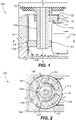
Fig. 1 is a cross-sectional side elevation view of an embodiment of a valve assembly constructed in accordance with the present disclosure, showing the guidance retainer rings; -
Fig. 2 is a plan view of the valve assembly ofFig. 1 , showing the flow bores through one of the guidance retainer rings; and -
Fig. 3 is a cross-sectional side elevation view of the valve assembly ofFig. 1 , showing the valve head, the valve stem, and the guidance retainer rings in a second position. - Reference will now be made to the drawings wherein like reference numerals identify similar structural features or aspects of the subject disclosure. For purposes of explanation and illustration, and not limitation, a partial view of an embodiment of a valve assembly in accordance with the disclosure is shown in
Fig. 1 and is designated generally byreference character 100. Other embodiments of systems in accordance with the disclosure, or aspects thereof, are provided inFigs. 2-3 , as will be described. The systems and methods described herein can be used to provide valve retainer guidance for movement of a valve stem within a housing. - The
valve assembly 100 includes avalve head 102. Avalve stem 104 extends from thevalve head 102 and into adrain bore 106 in ahousing 108. A firstguidance retainer ring 110 is mounted around thevalve stem 104 at a first axial location on thevalve stem 104. A secondguidance retainer ring 112 is mounted around thevalve stem 104 at a second axial location (along longitudinal axis A) on thevalve stem 104, spaced apart from the first axial location. - With reference now to
Fig. 2 , the firstguidance retainer ring 110 includes aninner ring 114 that forms a full 360° ring around thevalve stem 104. The firstguidance retainer ring 110 also includes anouter ring 116 spaced radially apart from theinner ring 114 relative to the longitudinal axis A shown inFig. 1 . Theouter ring 116 forms an incomplete ring, less than a full 360°, e.g. extending only about 240° around the circumference around the longitudinal axis A ofFig. 1 . Theouter ring 116 contacts thehousing 108. A pair ofarcuate flow bores 118 are defined through the firstguidance retainer ring 110 between theinner ring 114 and theouter ring 116. Threespokes 120 connect the inner andouter rings flow bores 118 allow for fluids to pass through thedrain bore 106, flowing through the firstguidance retainer ring 110. - Referring again to
Fig. 1 , the secondguidance retainer ring 112 can be structurally identical to the firstguidance retainer ring 110, and theouter ring 116 of each contacts thehousing 108. The incompleteouter ring 116 of the firstguidance retainer ring 110 is circumferentially offset by 180° relative to the incompleteouter ring 116 of the secondguidance retainer ring 112. This is shown inFig. 1 , where theouter ring 116 of the firstguidance retainer ring 110 extends more fully to the right as oriented inFig. 1 , and theouter ring 116 of the secondguidance retainer ring 112 extends more fully to the left as oriented inFig. 1 . In a first position, shown inFig. 1 , thevalve head 102 is spaced apart from anopening 122 of thevalve bore 106. This position allows flow through thedrain bore 106. In a second position, shown inFig. 3 , thevalve head 102 is sealed against theopening 122 of thevalve bore 106, preventing flow through thevalve bore 106. The first and secondguidance retainer rings valve head 102 andvalve stem 104 when moving between the first and second positions, i.e. when moving relative to thehousing 108 to open and close thevalve assembly 100. Thevalve stem 104 and the first and secondguidance retainer rings valve stem 104, i.e. in a direction to the right and left inFigs. 1 and3 . This reduces wear between thehousing 108 and the first and secondguidance retainer rings - The methods and systems of the present disclosure, as described above and shown in the drawings, provide for valve retainer guidance for movement of a valve stem within a housing with improved performance relative to traditional techniques. While the apparatus and methods of the subject disclosure have been shown and described with reference to preferred embodiments, those skilled in the art will readily appreciate that changes and/or modifications may be made thereto without departing from the scope of the invention as defined by the claims.
Claims (15)
- A valve assembly comprising:a valve head (102);a valve stem (104) extending from the valve head and into a drain bore (106) in a housing (108);a first guidance retainer ring (110) mounted around the valve stem at a first axial location on the valve stem; anda second guidance retainer ring (112) mounted around the valve stem at a second axial location on the valve stem spaced apart from the first axial location.
- The valve assembly as recited in claim 1, wherein the first guidance retainer ring (110) includes an inner ring (114) that forms a full 360° ring and an outer ring (116) spaced radially apart from the inner ring, wherein the outer ring forms an incomplete ring less than a full 360°.
- The valve assembly as recited in claim 2, wherein the outer ring (116) of the first guidance retainer ring (110) contacts the housing (108).
- The valve assembly as recited in claim 3, wherein the second guidance retainer ring (112) includes an inner ring that forms a full 360° ring and an outer ring spaced radially apart from the inner ring, wherein the outer ring forms an incomplete ring less than a full 360°.
- The valve assembly as recited in claim 4, wherein the outer ring of the second guidance retainer ring contacts the housing.
- The valve assembly as recited in claim 5, wherein the incomplete ring of the first guidance retainer ring is circumferentially offset relative to the incomplete ring of the second guidance retainer ring.
- The valve assembly as recited in claim 6, wherein the incomplete ring of the first guidance retainer ring is circumferentially offset by 180° relative to the incomplete ring of the second guidance retainer ring.
- The valve assembly as recited in claim 7, wherein in a first position the valve head (102) is spaced apart from an opening of the drain bore (106), and in a second position the valve head is sealed against the opening of the drain bore (106).
- The valve assembly as recited in claim 8, wherein the first and second guidance retainer rings (110, 112) follow the valve head (102) and valve stem (104) moving between the first and second positions when moving relative to the housing.
- The valve assembly as recited in claim 9, wherein the valve stem (104) and the first and second guidance retainer ring maintain a net of zero force in a radial direction relative to a longitudinal axis of the valve stem.
- The valve assembly as recited in claim 5, wherein at least one flow bore (118) is defined through the first guidance retainer ring between the inner ring and the outer ring of the first guidance retainer ring.
- The valve assembly as recited in claim 11, wherein the at least one flow bore (118) includes two arcuate bores, with three spokes (120) connecting the inner and outer rings of the first guidance retainer ring.
- The valve assembly as recited in claim 12, wherein at least one flow bore is defined through the second guidance retainer ring between the inner ring and the outer ring of the second guidance retainer ring.
- The valve assembly as recited in claim 13, wherein the at least one flow bore of the second guidance retainer ring includes two arcuate bores, with three spokes connecting the inner and outer rings of the second guidance retainer ring.
- The valve assembly as recited in claim 14, wherein the first and second guidance retainer rings are identical in structure to one another.
Applications Claiming Priority (1)
| Application Number | Priority Date | Filing Date | Title |
|---|---|---|---|
| US202063090524P | 2020-10-12 | 2020-10-12 |
Publications (1)
| Publication Number | Publication Date |
|---|---|
| EP3982019A1 true EP3982019A1 (en) | 2022-04-13 |
Family
ID=78134857
Family Applications (1)
| Application Number | Title | Priority Date | Filing Date |
|---|---|---|---|
| EP21202234.7A Pending EP3982019A1 (en) | 2020-10-12 | 2021-10-12 | Retainer guidance for rinsing valves |
Country Status (2)
| Country | Link |
|---|---|
| US (2) | US11555552B2 (en) |
| EP (1) | EP3982019A1 (en) |
Citations (4)
| Publication number | Priority date | Publication date | Assignee | Title |
|---|---|---|---|---|
| GB1527775A (en) * | 1975-11-24 | 1978-10-11 | Actrol Ind Pty Ltd | Pressure control valve |
| AU606060B2 (en) * | 1986-05-22 | 1991-01-31 | Donson Industries Pty. Ltd. | Water supply back flow preventer |
| EP0573865A1 (en) * | 1992-06-11 | 1993-12-15 | Karl Jeromin | Check valve |
| KR20130137748A (en) * | 2012-06-08 | 2013-12-18 | 수성밸브공업 주식회사 | Check valve |
Family Cites Families (11)
| Publication number | Priority date | Publication date | Assignee | Title |
|---|---|---|---|---|
| US1826639A (en) * | 1928-10-18 | 1931-10-06 | Stohr Rolf | Valve lifter for baths, lavatories, and the like |
| US2282212A (en) * | 1940-09-03 | 1942-05-05 | Chase Brass & Copper Co | Drain assembly |
| US2743078A (en) * | 1953-12-17 | 1956-04-24 | Jordan Walter | Suction device for the transfer of liquid from one container to another |
| US2989758A (en) * | 1958-03-31 | 1961-06-27 | Crane Co | Power actuated waste mechanism |
| US6023795A (en) * | 1998-04-09 | 2000-02-15 | Evac International Oy | Washbasin drain assembly |
| JP2001020350A (en) | 1999-07-12 | 2001-01-23 | Inax Corp | Hot water washing device |
| CA2739117C (en) | 2008-10-03 | 2014-05-27 | B/E Aerospace, Inc. | Rinse valve for vacuum waste system |
| US20100275357A1 (en) * | 2009-04-29 | 2010-11-04 | Nick Fuoco | Sink popup stopper drain assembly |
| US9057181B2 (en) * | 2012-11-09 | 2015-06-16 | Fluid Dynamics Holdings, LLC | Water flow valve for improving accuracy of meter readings in communication with a water distribution system |
| US10189194B2 (en) | 2014-12-05 | 2019-01-29 | Zurn Industries, Llc | Unitary diaphragm |
| CN209340557U (en) | 2018-12-06 | 2019-09-03 | 江苏雷利电机股份有限公司 | Shunt valve and toilet seat including the shunt valve |
-
2020
- 2020-12-04 US US17/111,767 patent/US11555552B2/en active Active
-
2021
- 2021-10-12 EP EP21202234.7A patent/EP3982019A1/en active Pending
-
2023
- 2023-01-13 US US18/096,681 patent/US11867305B2/en active Active
Patent Citations (4)
| Publication number | Priority date | Publication date | Assignee | Title |
|---|---|---|---|---|
| GB1527775A (en) * | 1975-11-24 | 1978-10-11 | Actrol Ind Pty Ltd | Pressure control valve |
| AU606060B2 (en) * | 1986-05-22 | 1991-01-31 | Donson Industries Pty. Ltd. | Water supply back flow preventer |
| EP0573865A1 (en) * | 1992-06-11 | 1993-12-15 | Karl Jeromin | Check valve |
| KR20130137748A (en) * | 2012-06-08 | 2013-12-18 | 수성밸브공업 주식회사 | Check valve |
Also Published As
| Publication number | Publication date |
|---|---|
| US11867305B2 (en) | 2024-01-09 |
| US20230167916A1 (en) | 2023-06-01 |
| US20220112963A1 (en) | 2022-04-14 |
| US11555552B2 (en) | 2023-01-17 |
Similar Documents
| Publication | Publication Date | Title |
|---|---|---|
| US8403296B2 (en) | Metal seat seal with flexible sealing edge | |
| US9010725B2 (en) | Valve vented redundant stem seal system | |
| US9915359B2 (en) | Double piston effect lip seal seating assemblies | |
| US7032880B2 (en) | Valve with pressure adaptable seat | |
| US9915349B2 (en) | Dynamically non contacting seal | |
| EP3857020B1 (en) | Piston load ring seal configurations | |
| US20120080634A1 (en) | valve bore sealing method and apparatus | |
| WO2013103715A1 (en) | Valve seat retention pin | |
| US9347333B2 (en) | Brush ring seal | |
| CN117432864B (en) | Throttling device for valve | |
| CN104358884B (en) | Seal Kits for Fluid Valves | |
| EP2333384A1 (en) | Metal seal for ball valves and ball valve comprising said seal | |
| US9903496B2 (en) | Lining for mechanical joints | |
| CN107208835A (en) | Do not stop construction method | |
| KR101167271B1 (en) | Triple eccentric butterfly valve of bi-directional tightness structure | |
| US11555552B2 (en) | Retainer guidance for rinsing valves | |
| US4971098A (en) | Valve and improved seat seal therefor | |
| US8668014B2 (en) | Subsurface safety valve for high temperature and high pressure wells | |
| EP3258144A1 (en) | Piston ring assembly | |
| WO2016171857A1 (en) | Valve vented redundant stem seal system | |
| US11635142B2 (en) | Dual barrier seal | |
| US10184567B2 (en) | Spring ring valve seat and butterfly valve with spring ring valve seat | |
| KR101558308B1 (en) | Ball valve and method for manufacturing the same | |
| US9541219B2 (en) | Valve packing shield for use in hydrocarbon operations | |
| US20170307085A1 (en) | Circumferential shaft seal with radial displacement control |
Legal Events
| Date | Code | Title | Description |
|---|---|---|---|
| PUAI | Public reference made under article 153(3) epc to a published international application that has entered the european phase |
Free format text: ORIGINAL CODE: 0009012 |
|
| STAA | Information on the status of an ep patent application or granted ep patent |
Free format text: STATUS: THE APPLICATION HAS BEEN PUBLISHED |
|
| AK | Designated contracting states |
Kind code of ref document: A1 Designated state(s): AL AT BE BG CH CY CZ DE DK EE ES FI FR GB GR HR HU IE IS IT LI LT LU LV MC MK MT NL NO PL PT RO RS SE SI SK SM TR |
|
| STAA | Information on the status of an ep patent application or granted ep patent |
Free format text: STATUS: REQUEST FOR EXAMINATION WAS MADE |
|
| 17P | Request for examination filed |
Effective date: 20221013 |
|
| RBV | Designated contracting states (corrected) |
Designated state(s): AL AT BE BG CH CY CZ DE DK EE ES FI FR GB GR HR HU IE IS IT LI LT LU LV MC MK MT NL NO PL PT RO RS SE SI SK SM TR |
|
| P01 | Opt-out of the competence of the unified patent court (upc) registered |
Effective date: 20230922 |
|
| STAA | Information on the status of an ep patent application or granted ep patent |
Free format text: STATUS: EXAMINATION IS IN PROGRESS |
|
| 17Q | First examination report despatched |
Effective date: 20240614 |
|
| GRAP | Despatch of communication of intention to grant a patent |
Free format text: ORIGINAL CODE: EPIDOSNIGR1 |
|
| STAA | Information on the status of an ep patent application or granted ep patent |
Free format text: STATUS: GRANT OF PATENT IS INTENDED |