EP3982016A1 - Sealing device - Google Patents
Sealing device Download PDFInfo
- Publication number
- EP3982016A1 EP3982016A1 EP20818041.4A EP20818041A EP3982016A1 EP 3982016 A1 EP3982016 A1 EP 3982016A1 EP 20818041 A EP20818041 A EP 20818041A EP 3982016 A1 EP3982016 A1 EP 3982016A1
- Authority
- EP
- European Patent Office
- Prior art keywords
- periphery side
- outer periphery
- elastic body
- inner periphery
- sealing device
- Prior art date
- Legal status (The legal status is an assumption and is not a legal conclusion. Google has not performed a legal analysis and makes no representation as to the accuracy of the status listed.)
- Pending
Links
Images

Classifications
-
- F—MECHANICAL ENGINEERING; LIGHTING; HEATING; WEAPONS; BLASTING
- F16—ENGINEERING ELEMENTS AND UNITS; GENERAL MEASURES FOR PRODUCING AND MAINTAINING EFFECTIVE FUNCTIONING OF MACHINES OR INSTALLATIONS; THERMAL INSULATION IN GENERAL
- F16J—PISTONS; CYLINDERS; SEALINGS
- F16J15/00—Sealings
- F16J15/16—Sealings between relatively-moving surfaces
- F16J15/164—Sealings between relatively-moving surfaces the sealing action depending on movements; pressure difference, temperature or presence of leaking fluid
-
- F—MECHANICAL ENGINEERING; LIGHTING; HEATING; WEAPONS; BLASTING
- F16—ENGINEERING ELEMENTS AND UNITS; GENERAL MEASURES FOR PRODUCING AND MAINTAINING EFFECTIVE FUNCTIONING OF MACHINES OR INSTALLATIONS; THERMAL INSULATION IN GENERAL
- F16J—PISTONS; CYLINDERS; SEALINGS
- F16J15/00—Sealings
- F16J15/16—Sealings between relatively-moving surfaces
- F16J15/32—Sealings between relatively-moving surfaces with elastic sealings, e.g. O-rings
- F16J15/3204—Sealings between relatively-moving surfaces with elastic sealings, e.g. O-rings with at least one lip
- F16J15/3232—Sealings between relatively-moving surfaces with elastic sealings, e.g. O-rings with at least one lip having two or more lips
-
- F—MECHANICAL ENGINEERING; LIGHTING; HEATING; WEAPONS; BLASTING
- F16—ENGINEERING ELEMENTS AND UNITS; GENERAL MEASURES FOR PRODUCING AND MAINTAINING EFFECTIVE FUNCTIONING OF MACHINES OR INSTALLATIONS; THERMAL INSULATION IN GENERAL
- F16J—PISTONS; CYLINDERS; SEALINGS
- F16J15/00—Sealings
- F16J15/16—Sealings between relatively-moving surfaces
- F16J15/32—Sealings between relatively-moving surfaces with elastic sealings, e.g. O-rings
- F16J15/3204—Sealings between relatively-moving surfaces with elastic sealings, e.g. O-rings with at least one lip
-
- F—MECHANICAL ENGINEERING; LIGHTING; HEATING; WEAPONS; BLASTING
- F16—ENGINEERING ELEMENTS AND UNITS; GENERAL MEASURES FOR PRODUCING AND MAINTAINING EFFECTIVE FUNCTIONING OF MACHINES OR INSTALLATIONS; THERMAL INSULATION IN GENERAL
- F16J—PISTONS; CYLINDERS; SEALINGS
- F16J15/00—Sealings
- F16J15/16—Sealings between relatively-moving surfaces
- F16J15/32—Sealings between relatively-moving surfaces with elastic sealings, e.g. O-rings
- F16J15/3204—Sealings between relatively-moving surfaces with elastic sealings, e.g. O-rings with at least one lip
- F16J15/3224—Sealings between relatively-moving surfaces with elastic sealings, e.g. O-rings with at least one lip capable of accommodating changes in distances or misalignment between the surfaces, e.g. able to compensate for defaults of eccentricity or angular deviations
-
- F—MECHANICAL ENGINEERING; LIGHTING; HEATING; WEAPONS; BLASTING
- F16—ENGINEERING ELEMENTS AND UNITS; GENERAL MEASURES FOR PRODUCING AND MAINTAINING EFFECTIVE FUNCTIONING OF MACHINES OR INSTALLATIONS; THERMAL INSULATION IN GENERAL
- F16J—PISTONS; CYLINDERS; SEALINGS
- F16J15/00—Sealings
- F16J15/16—Sealings between relatively-moving surfaces
- F16J15/32—Sealings between relatively-moving surfaces with elastic sealings, e.g. O-rings
- F16J15/3248—Sealings between relatively-moving surfaces with elastic sealings, e.g. O-rings provided with casings or supports
- F16J15/3252—Sealings between relatively-moving surfaces with elastic sealings, e.g. O-rings provided with casings or supports with rigid casings or supports
- F16J15/3256—Sealings between relatively-moving surfaces with elastic sealings, e.g. O-rings provided with casings or supports with rigid casings or supports comprising two casing or support elements, one attached to each surface, e.g. cartridge or cassette seals
- F16J15/3264—Sealings between relatively-moving surfaces with elastic sealings, e.g. O-rings provided with casings or supports with rigid casings or supports comprising two casing or support elements, one attached to each surface, e.g. cartridge or cassette seals the elements being separable from each other
-
- F—MECHANICAL ENGINEERING; LIGHTING; HEATING; WEAPONS; BLASTING
- F16—ENGINEERING ELEMENTS AND UNITS; GENERAL MEASURES FOR PRODUCING AND MAINTAINING EFFECTIVE FUNCTIONING OF MACHINES OR INSTALLATIONS; THERMAL INSULATION IN GENERAL
- F16J—PISTONS; CYLINDERS; SEALINGS
- F16J15/00—Sealings
- F16J15/16—Sealings between relatively-moving surfaces
- F16J15/32—Sealings between relatively-moving surfaces with elastic sealings, e.g. O-rings
- F16J15/3268—Mounting of sealing rings
- F16J15/3276—Mounting of sealing rings with additional static sealing between the sealing, or its casing or support, and the surface on which it is mounted
-
- F—MECHANICAL ENGINEERING; LIGHTING; HEATING; WEAPONS; BLASTING
- F16—ENGINEERING ELEMENTS AND UNITS; GENERAL MEASURES FOR PRODUCING AND MAINTAINING EFFECTIVE FUNCTIONING OF MACHINES OR INSTALLATIONS; THERMAL INSULATION IN GENERAL
- F16J—PISTONS; CYLINDERS; SEALINGS
- F16J15/00—Sealings
- F16J15/16—Sealings between relatively-moving surfaces
- F16J15/32—Sealings between relatively-moving surfaces with elastic sealings, e.g. O-rings
- F16J15/328—Manufacturing methods specially adapted for elastic sealings
-
- F—MECHANICAL ENGINEERING; LIGHTING; HEATING; WEAPONS; BLASTING
- F16—ENGINEERING ELEMENTS AND UNITS; GENERAL MEASURES FOR PRODUCING AND MAINTAINING EFFECTIVE FUNCTIONING OF MACHINES OR INSTALLATIONS; THERMAL INSULATION IN GENERAL
- F16J—PISTONS; CYLINDERS; SEALINGS
- F16J15/00—Sealings
- F16J15/16—Sealings between relatively-moving surfaces
- F16J15/32—Sealings between relatively-moving surfaces with elastic sealings, e.g. O-rings
- F16J15/3284—Sealings between relatively-moving surfaces with elastic sealings, e.g. O-rings characterised by their structure; Selection of materials
Definitions
- the present invention relates to a sealing device.
- a sealing device including a plurality of relatively rotatable members has been widely used.
- a sealing device including: one of two relatively rotatable members, for example, a slinger fixed to a rotating shaft; and the other of the two relatively rotatable members, for example, a sealing device main body fixed to an inner periphery side surface of a shaft hole of a housing (for example, see Patent Literature 1).
- Such a sealing device is used to seal a lubricant or the like in an internal space of a vehicle, a general-purpose machine, or the like.
- the slinger is provided with a flange, and this flange prevents or reduces invasion of dirt and dust from the atmosphere side to the internal space side. Therefore, such a sealing device is used in an environment full of dirt or dust, for example, a truck of a railroad vehicle, a truck of a sintering pallet, a construction machine, a trunnion-type suspension of a truck, and an agricultural machine.
- Patent Literature 1 Japanese Patent No. 4978074
- the sealing device main body of such a sealing device includes: an annular reinforcement ring; and an elastic body part made of a rubber material that is formed so as to cover the reinforcement ring integrally therewith.
- the reinforcement ring, the elastic body part is bonded to the reinforcement ring by cross-linking adhesion, whereby the elastic body part is formed integrally with the reinforcement ring.
- holes for improving the adhesion force between the elastic body part and the reinforcement ring are provided at regular intervals in the reinforcement ring, and the inside of each hole is filled with a rubber material.
- grooves formed by holding the reinforcement ring at the time of the cross-linking adhesion are provided at regular intervals on an internal space side surface of the elastic body part.
- the conventional sealing device is required to have a structure in which the occurrence of such a through crack in the rubber material of the elastic body part can be further suppressed.
- the present invention has been made in view of the above-mentioned problem, and it is an object of the present invention to provide a sealing device in which the occurrence of a through crack in a rubber material of an elastic body part can be further suppressed.
- a sealing device is a sealing device that seals a gap between: an annular outer periphery side member; and an annular inner periphery side member at least partially surrounded by the outer periphery side member, the outer periphery side member and the inner periphery side member being relatively rotatable to each other with respect to an axis, the sealing device being characterized by including: a sealing device main body to be attached to the outer periphery side member; and a slinger to be attached to the inner periphery side member, wherein the sealing device main body includes: an annular reinforcement ring centered on the axis; and an annular elastic body part that is made of an elastic body attached to the reinforcement ring and is centered on the axis, a through hole that passes through a portion between an internal space side surface and an atmosphere side surface of the reinforcement ring is formed in the reinforcement ring, a positioning part for fixing a position of the reinforcement ring at
- a thickness of the elastic body part formed on an atmosphere side of the reinforcement ring is thicker than a thickness of the elastic body part formed on an internal space side of the reinforcement ring.
- the positioning part is an annular groove part that is formed on an outer periphery side and/or an inner periphery side of the through hole and is concave from an internal space side to an atmosphere side.
- a sealing device of the present invention the occurrence of a through crack in a rubber material of an elastic body part can be further suppressed.
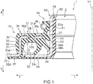
- Fig. 1 is a sectional view for showing a schematic configuration of a sealing device 1 according to the embodiment of the present invention.
- Fig. 2 is an enlarged sectional view for showing a schematic configuration of the vicinity of a through hole 24 and a positioning part 36 of the sealing device 1.
- Figs. 1 and 2 only a one-side portion of the sealing device 1 is shown.
- the sealing device 1 is used in an environment full of dirt or dust, for example, a truck of a railroad vehicle, a truck of a sintering pallet, a construction machine, a trunnion-type suspension of a truck, and an agricultural machine (such as a tiller, a tractor, and a rice transplanter).
- the sealing device 1 has a role in sealing a gap between: an annular outer periphery side member; and an annular inner periphery side member at least partially surrounded by the outer periphery side member, the outer periphery side member and the inner periphery side member being relatively rotatable to each other.
- the target to which the sealing device 1 is applied is not limited to the above.
- the sealing device 1 is a sealing device that seals a gap between: an annular outer periphery side member 101; and an annular inner periphery side member 102 at least partially surrounded by the outer periphery side member 101, the outer periphery side member 101 and the inner periphery side member 102 being relatively rotatable to each other with respect to an axis Y1.
- the sealing device 1 includes: a sealing device main body 10 to be attached to the outer periphery side member 101; and a slinger 40 to be attached to the inner periphery side member 102.
- the sealing device main body 10 includes: an annular reinforcement ring 20 centered on the axis Y1; and an annular elastic body part 30 that is made of an elastic body attached to the reinforcement ring 20 and is centered on the axis Y1.
- the through hole 24 that passes through a portion between an internal space side surface and an atmosphere side surface of the reinforcement ring 20 is formed in the reinforcement ring 20, and the positioning part 36 for fixing the position of the reinforcement ring 20 at the time of vulcanization is formed on an internal space side surface of the elastic body part 30.
- the through hole 24 and the positioning part 36 are formed at positions separated in the radial direction.
- a configuration of the sealing device 1 will be specifically described.
- one (an arrow a direction) of the directions of the axis Y1 (hereinafter, also referred to as the axis Y1 direction) corresponding to the axis of the sealing device 1 in Figs. 1 and 2 is defined as the internal space side, and another (an arrow b direction) thereof is defined as the atmosphere side.
- one (an arrow c direction) of the extending directions orthogonal to the axis Y1 (hereinafter, also referred to as the radial direction) of the sealing device 1 in Figs. 1 and 2 is defined as the inner periphery side, and another (an arrow d direction) thereof is defined as the outer periphery side.
- the positional relation and the direction of each member in the following description respectively represent the positional relation and the direction thereof in the drawings, and do not represent the positional relation and the direction thereof when each member is incorporated in an actual vehicle or the like.
- the outer shape of the sealing device 1 is formed in a circular or substantially circular shape around the axis Y1, and a cylindrical or substantially cylindrical opening part 2 is formed in a central portion of the sealing device 1.
- the sealing device 1 includes: the sealing device main body 10 having a circular or substantially circular shape around the axis Y1; and the slinger 40 that is formed on the inner periphery side of the sealing device main body 10 and has a cylindrical or substantially cylindrical shape around the axis Y1.
- the outer shape of the sealing device main body 10 is formed in a circular or substantially circular shape around the axis Y1.
- the sealing device main body 10 includes: the reinforcement ring 20 having a circular or substantially cylindrical shape around the axis Y1; and the elastic body part 30 that is formed by an elastic body molded integrally with the reinforcement ring 20 and has a circular or substantially circular shape around the axis Y1.
- the elastic body of the elastic body part 30 is, for example, a rubber material such as fluororubber and acrylic rubber.
- the reinforcement ring 20 is made of, for example, metal, and is produced by press working and forging, and the elastic body part 30 is molded by cross-linking (vulcanization) molding using a mold.
- the reinforcement ring 20 includes: a tubular part 21; an annular inner periphery side flange part 22 that extends to the inner periphery side from an internal space side end portion corresponding to an end portion on the internal space side of the tubular part 21; and an annular outer periphery side flange part 23 that extends to the outer periphery side from an atmosphere side end portion corresponding to an end portion on the atmosphere side of the tubular part 21.
- the tubular part 21 extends parallel or substantially parallel to the axis Y1 direction, and is formed in a cylindrical or substantially cylindrical shape around the axis Y1.
- the internal space side end portion, the atmosphere side end portion, an inner periphery side surface, and an outer periphery side surface of the tubular part 21 are buried in the elastic body part 30.
- the inner periphery side flange part 22 is a flange part that extends parallel or substantially parallel to the radial direction, extends to the inner periphery side from the internal space side end portion of the tubular part 21, and has a circular or substantially circular shape around the axis Y1.
- An internal space side surface, an atmosphere side surface, an inner periphery side end portion, and an outer periphery side end portion (the internal space side end portion of the tubular part 21) of the inner periphery side flange part 22 are buried in the elastic body part 30.
- the through hole 24 that passes through a portion between the internal space side surface and the atmosphere side surface of the inner periphery side flange part 22 of the reinforcement ring 20 is formed in a central portion in the radial direction of the inner periphery side flange part 22.
- the through hole 24 is formed in, for example, a cylindrical or substantially cylindrical shape, and a plurality (for example, eight) of the through holes 24 are formed at equal angular intervals or substantially equal angular intervals concentrically or substantially concentrically from the axis Y1.
- the diameter of the through hole 24 is, for example, 3 mm, and the through hole 24 is filled with the elastic body of the elastic body part 30.
- the outer periphery side flange part 23 is a flange part that extends parallel or substantially parallel to the radial direction, extends to the outer periphery side from the atmosphere side end portion of the tubular part 21, and has a circular or substantially circular shape around the axis Y1.
- An inner periphery side end portion (the atmosphere side end portion of the tubular part 21) and an atmosphere side surface of the outer periphery side flange part 23 are buried in the elastic body part 30, and a large portion of an outer periphery side end portion and an internal space side surface of the outer periphery side flange part 23 are exposed from the elastic body part 30.
- the elastic body part 30 includes an internal space side elastic body part 31, an atmosphere side elastic body part 32, a seal lip part 33, and a dust lip part 34.
- the internal space side elastic body part 31 includes: an outer periphery side portion 31d that extends parallel or substantially parallel to the axis Y1 direction and is formed in a cylindrical or substantially cylindrical shape around the axis Y1; and an internal space side portion 31a that extends parallel or substantially parallel to the radial direction, extends to the outer periphery side from an internal space side end portion of the outer periphery side portion 31d, and has a circular or substantially circular shape around the axis Y1.
- the internal space side elastic body part 31 covers the outer periphery side surface of the tubular part 21, the internal space side end portion of the tubular part 21 (the outer periphery side end portion of the inner periphery side flange part 22), and the internal space side surface of the inner periphery side flange part 22.
- the internal space side elastic body part 31 includes an outer periphery side lip part 35 that extends to the outer periphery side from the outer periphery side portion 31d and has a circular or substantially circular shape around the axis Y1.
- the positioning part 36 for fixing the position of the reinforcement ring 20 at the time of vulcanization is formed in the internal space side portion 31a of the internal space side elastic body part 31.
- the positioning part 36 is an annular groove part that is formed on the outer periphery side and/or the inner periphery side of the through hole 24 and is concave from the internal space side to the atmosphere side.
- the positioning part 36 includes an inner periphery side positioning part 36c and an outer periphery side positioning part 36d.
- the inner periphery side positioning part 36c is a groove part that is rectangular or substantially rectangular in a cross-section view and is concave from an internal space side surface 31aa of the internal space side portion 31a of the internal space side elastic body part 31 toward the internal space side surface of the inner periphery side flange part 22 of the reinforcement ring 20, on the inner periphery side of the through hole 24.
- the inner periphery side positioning part 36c is a circumferential groove that is formed in a bottomed cylindrical or substantially bottomed cylindrical shape around the axis Y1.
- the inner periphery side positioning part 36c has a circular or substantially circular bottom surface 36ct that extends parallel or substantially parallel to the radial direction, at a position having a predetermined depth on the atmosphere side from the internal space side surface 31aa of the internal space side portion 31a of the inner periphery side positioning part 36c.
- the bottom surface 36ct does not reach the internal space side surface of the inner periphery side flange part 22 of the reinforcement ring 20, and defines the boundary on the atmosphere side of the inner periphery side positioning part 36c.
- An inner periphery side surface 36cc is formed on the inner periphery side of the bottom surface 36ct of the inner periphery side positioning part 36c, and an outer periphery side surface 36cd is formed on the outer periphery side of the bottom surface 36ct of the inner periphery side positioning part 36c.
- the inner periphery side surface 36cc of the inner periphery side positioning part 36c is a surface that defines the boundary on the inner periphery side of the inner periphery side positioning part 36c
- the outer periphery side surface 36cd of the inner periphery side positioning part 36c is a surface that defines the boundary on the outer periphery side of the inner periphery side positioning part 36c.
- the inner periphery side surface 36cc of the inner periphery side positioning part 36c is a cylindrical or substantially cylindrical surface that extends along the axis Y1 direction and extends toward the internal space side from the edge on the inner periphery side of the bottom surface 36ct with the axis Y1 being centered.
- the outer periphery side surface 36cd of the inner periphery side positioning part 36c is a cylindrical or substantially cylindrical surface that extends along the axis Y1 direction toward the internal space side from the edge on the outer periphery side of the bottom surface 36ct with the axis Y1 being centered.
- the outer periphery side positioning part 36d is a groove part that is rectangular or substantially rectangular in a cross-section view and is concave from the internal space side surface 31aa of the internal space side portion 31a of the internal space side elastic body part 31 toward the internal space side surface of the inner periphery side flange part 22 of the reinforcement ring 20, on the outer periphery side of the through hole 24.
- the outer periphery side positioning part 36d is a circumferential groove that is formed in a bottomed cylindrical or substantially bottomed cylindrical shape around the axis Y1.
- the outer periphery side positioning part 36d has a circular or substantially circular bottom surface 36dt that extends parallel or substantially parallel to the radial direction, at a position having a predetermined depth on the atmosphere side from the internal space side surface 31aa of the internal space side portion 31a of the internal space side elastic body part 31.
- the bottom surface 36dt does not reach the internal space side surface of the inner periphery side flange part 22 of the reinforcement ring 20, and defines the boundary on the atmosphere side of the outer periphery side positioning part 36d.
- An inner periphery side surface 36dc is formed on the inner periphery side of the bottom surface 36dt of the outer periphery side positioning part 36d
- an outer periphery side surface 36dd is formed on the outer periphery side of the bottom surface 36dt of the outer periphery side positioning part 36d.
- the inner periphery side surface 36dc of the outer periphery side positioning part 36d is a surface that defines the boundary on the inner periphery side of the outer periphery side positioning part 36d
- the outer periphery side surface 36dd of the outer periphery side positioning part 36d is a surface that defines the boundary on the outer periphery side of the outer periphery side positioning part 36d.
- the inner periphery side surface 36dc of the outer periphery side positioning part 36d is a cylindrical or substantially cylindrical surface that extends along the axis Y1 direction and extends toward the internal space side from the edge on the inner periphery side of the bottom surface 36dt with the axis Y1 being centered.
- the outer periphery side surface 36dd of the outer periphery side positioning part 36d is a cylindrical or substantially cylindrical surface that extends along the axis Y1 direction toward the internal space side from the edge on the outer periphery side of the bottom surface 36dt with the axis Y1 being centered.
- the through hole 24 and the positioning part 36 are formed at positions separated in the radial direction.
- the outer periphery side surface 36cd of the inner periphery side positioning part 36c is formed on the inner periphery side from a peripheral surface of the through hole 24, and the inner periphery side surface 36dc of the outer periphery side positioning part 36d is formed on the outer periphery side from the peripheral surface of the through hole 24.
- a predetermined width W1 is formed between the outer periphery side surface 36cd of the inner periphery side positioning part 36c and the peripheral surface of the through hole 24, and a predetermined width W2 is formed between the inner periphery side surface 36dc of the outer periphery side positioning part 36d and the peripheral surface of the through hole 24.
- the entire bottom surface 36ct of the inner periphery side positioning part 36c and the entire bottom surface 36dt of the outer periphery side positioning part 36d are opposed to the internal space side surface 22a of the inner periphery side flange part 22.
- the atmosphere side elastic body part 32 includes an inner periphery side portion 32c that extends parallel or substantially parallel to the axis Y1 direction and is formed in a cylindrical or substantially cylindrical shape around the axis Y1. Moreover, the atmosphere side elastic body part 32 includes: an outer periphery atmosphere side portion 32d that extends parallel or substantially parallel to the radial direction, extends to the outer periphery side from an atmosphere side end portion of the inner periphery side portion 32c, and has a circular or substantially circular shape around the axis Y1; and an inner periphery atmosphere side portion 32b that extends parallel or substantially parallel to the radial direction, extends to the inner periphery side from an internal space side end portion of the inner periphery side portion 32c, and has a circular or substantially circular shape around the axis Y1.
- the atmosphere side elastic body part 32 covers the atmosphere side surface of the outer periphery side flange part 23, the inner periphery side end portion of the outer periphery side flange part 23 (the atmosphere side end portion of the tubular part 21), the inner periphery side surface of the tubular part 21, the internal space side end portion of the tubular part 21 (the outer periphery side end portion of the inner periphery side flange part 22), and the atmosphere side surface of the inner periphery side flange part 22 of the reinforcement ring 20.
- a thickness T1 of the inner periphery atmosphere side portion 32b of the elastic body part 30 formed on the atmosphere side of the reinforcement ring 20 is thicker than a thickness T2 of the internal space side portion 31a of the elastic body part 30 formed on the internal space side of the reinforcement ring 20.
- An atmosphere side positioning part 37 for fixing the position of the reinforcement ring 20 at the time of vulcanization is formed on an outer periphery atmosphere side surface of the outer periphery atmosphere side portion 32d of the atmosphere side elastic body part 32.
- the atmosphere side positioning part 37 is a groove part that is rectangular or substantially rectangular in a cross-section view and is concave from the outer periphery atmosphere side surface of the outer periphery atmosphere side portion 32d toward the atmosphere side surface of the outer periphery side flange part 23 of the reinforcement ring 20, in a central portion in the radial direction of the outer periphery atmosphere side portion 32d.
- the atmosphere side positioning part 37 is a circumferential groove that is formed in a bottomed cylindrical or substantially bottomed cylindrical shape around the axis Y1.
- the inner periphery atmosphere side portion 32b of the atmosphere side elastic body part 32 is connected to the internal space side portion 31a of the internal space side elastic body part 31 by filling the inside of the through hole 24 of the inner periphery side flange part 22 of the reinforcement ring 20 with the elastic body, whereby the adhesion force between the reinforcement ring 20 and the elastic body part 30 can be improved.
- the seal lip part 33 further extends to the internal space side as progress from an inner periphery side end portion of the internal space side portion 31a of the internal space side elastic body part 31 toward the inner periphery side, and is formed in a truncated conical or substantially truncated conical shape, and the seal lip part 33 includes a lip leading end part 33a at its leading end.
- the lip leading end part 33a is a circular or substantially circular lip whose cross-sectional shape is a wedge shape that is convex toward the inner periphery side, and the lip leading end part 33a is formed so as to closely contact the slinger 40 slidably together with the slinger 40.
- a garter spring 38 that presses the lip leading end part 33a to the inner periphery side in the radial direction is fitted on the outer periphery side of the lip leading end part 33a.
- the dust lip part 34 includes a first dust lip part 34a, a second dust lip part 34b, and a third dust lip part 34c in the stated order from the internal space side.
- the first dust lip part 34a is a truncated conical or substantially truncated conical lip that further extends to the atmosphere side as progress from the inner periphery side end portion of the internal space side portion 31a of the internal space side elastic body part 31 toward the inner periphery side, and the first dust lip part 34a is formed so as to closely contact the slinger 40 slidably together therewith.
- the second dust lip part 34b is a truncated conical or substantially truncated conical lip that further extends to the atmosphere side as progress from an inner periphery side end portion of the inner periphery atmosphere side portion 32b of the atmosphere side elastic body part 32 toward the inner periphery side, and the second dust lip part 34b is formed so as to closely contact the slinger 40 slidably together therewith.
- the third dust lip part 34c is a truncated conical or substantially truncated conical lip that further extends to the outer periphery side as progress from the inner periphery side end portion of the inner periphery atmosphere side portion 32b of the atmosphere side elastic body part 32 toward the atmosphere side, and the third dust lip part 34c is formed so as to closely contact the slinger 40 slidably together therewith.
- the slinger 40 is formed on the inner periphery side of the sealing device main body 10, and the outer shape of the slinger 40 is formed in a circular or substantially circular shape around the axis Y1.
- the slinger 40 includes: a reinforcement ring 50 having a circular or substantially cylindrical shape around the axis Y1; and an elastic body part 60 that is formed by an elastic body molded integrally with the reinforcement ring 50 and has a circular or substantially circular shape around the axis Y1.
- the elastic body of the elastic body part 60 is, for example, a rubber material such as fluororubber and acrylic rubber.
- the reinforcement ring 50 is made of, for example, metal, and is produced by press working and forging, and the elastic body part 60 is molded by cross-linking (vulcanization) molding using a mold.
- the reinforcement ring 50 includes: a tubular part 51; and an annular outer periphery side flange part 52 that extends to the outer periphery side from an atmosphere side end portion 51b corresponding to an end portion on the atmosphere side of the tubular part 51.
- the tubular part 51 extends parallel or substantially parallel to the axis Y1 direction, and is formed in a cylindrical or substantially cylindrical shape around the axis Y1.
- the atmosphere side end portion and an inner periphery side surface of the tubular part 51 are buried in the elastic body part 60, and an internal space side end portion and an outer periphery side surface of the tubular part 51 are exposed from the elastic body part 60.
- the outer periphery side surface of the tubular part 51 closely contacts the seal lip part 33, the first dust lip part 34a, and the second dust lip part 34b slidably together therewith.
- the outer periphery side flange part 52 is a flange part that extends parallel or substantially parallel to the radial direction, extends to the outer periphery side from the atmosphere side end portion of the tubular part 51, and has a circular or substantially circular shape around the axis Y1.
- An outer periphery side end portion, an inner periphery side end portion (the atmosphere side end portion of the tubular part 51), and an atmosphere side surface of the outer periphery side flange part 52 are buried in the elastic body part 60, and an internal space side surface of the outer periphery side flange part 52 is exposed from the elastic body part 60.
- the internal space side surface 52a of the outer periphery side flange part 52 closely contacts the third dust lip part 34c slidably together therewith.
- the elastic body part 60 includes: an inner periphery side portion 61 that extends parallel or substantially parallel to the axis Y1 direction and is formed in a cylindrical or substantially cylindrical shape around the axis Y1; and an atmosphere side portion 62 that extends parallel or substantially parallel to the radial direction, extends to the outer periphery side from an atmosphere side end portion of the inner periphery side portion 61, and has a circular or substantially circular shape around the axis Y1.
- the elastic body part 60 includes an inner periphery side lip part 63 that extends to the inner periphery side from the inner periphery side portion 61 and has a circular or substantially circular shape around the axis Y1.
- the inner periphery side portion 61 of the elastic body part 60 covers the inner periphery side surface and the atmosphere side end portion of the tubular part 51.
- the atmosphere side portion 62 of the elastic body part 60 covers the inner periphery side end portion (the atmosphere side end portion of the inner periphery side portion 61), the atmosphere side surface, and the outer periphery side end portion of the atmosphere side portion 62.
- An outer periphery side end portion of the atmosphere side portion 62 of the elastic body part 60 is opposed to the outer periphery atmosphere side portion 32d of the atmosphere side elastic body part 32 of the elastic body part 30 with a predetermined clearance therebetween, and a gap G is formed between the outer periphery side end portion of the atmosphere side portion 62 of the elastic body part 60 and the outer periphery atmosphere side portion 32d of the atmosphere side elastic body part 32.
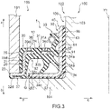
- FIG. 3 is a sectional view showing a schematic configuration of the sealing structure 100 corresponding to the state where the sealing device 1 according to the embodiment of the present invention is incorporated in a sealing target. In Fig. 3 , only a one-side portion of the sealing structure 100 and the sealing device 1 is shown.
- the sealing structure 100 is configured by incorporating the sealing device 1 in an annular gap between: the annular outer periphery side member 101; and the annular inner periphery side member 102 at least partially surrounded by the outer periphery side member 101, the outer periphery side member 101 and the inner periphery side member 102 being relatively rotatable to each other with respect to the axis Y1, and the sealing structure 100 is intended to achieve sealing of the annular gap between the outer periphery side member 101 and the inner periphery side member 102.
- the inner periphery side member 102 includes: a rod-like part 103 that extends parallel or substantially parallel to the axis Y1 direction and is formed in a columnar or substantially columnar shape around the axis Y1; and an outer periphery side flange part 104 that extends parallel or substantially parallel to the radial direction, extends to the outer periphery side from an atmosphere side end portion 103b of the rod-like part 103, and has a circular or substantially circular shape around the axis Y1.
- the outer periphery side member 101 is arranged on the outer periphery side of the inner periphery side member 102, and an opening part 105 having a cylindrical or substantially cylindrical shape around the axis Y1 is formed in the outer periphery side member 101.
- the inner periphery side member 102 is inserted in the opening part 105 of the outer periphery side member 101, and an annular space is formed between the opening part 105 and an outer periphery side surface of the rod-like part 103 of the inner periphery side member 102. That is, the outer periphery side member 101, the rod-like part 103 of the inner periphery side member 102, and the outer periphery side flange part 104 thereof form an accommodating part 106 for accommodating the sealing device 1.
- the accommodating part 106 is concave from the internal space side to the atmosphere side of the outer periphery side member 101 and the inner periphery side member 102, and a predetermined clearance is formed between the outer periphery side member 101 and the outer periphery side flange part 104 of the inner periphery side member 102.
- the slinger 40 of the sealing device 1 is fixed by, for example, interference fit to the outer periphery side surface of the rod-like part 103 of the inner periphery side member 102, by means of the inner periphery side lip part 63 of the inner periphery side portion 61 of the elastic body part 60, and the atmosphere side portion 62 of the elastic body part 60 of the slinger 40 closely contacts an internal space side surface of the outer periphery side flange part 104 of the inner periphery side member 102.
- the sealing device main body 10 of the sealing device 1 is fixed by, for example, interference fit to the opening part 105 of the outer periphery side member 101, by means of the outer periphery side lip part 35 of the internal space side elastic body part 31 of the elastic body part 30, and the internal space side surface of the outer periphery side flange part 23 of the sealing device main body 10 closely contacts an atmosphere side end portion of the outer periphery side member 101.
- the seal lip part 33 of the elastic body part 30 of the sealing device main body 10 of the sealing device 1 and the first dust lip part 34a and the second dust lip part 34b of the dust lip part 34 thereof closely contact the outer periphery side surface of the tubular part 51 of the slinger 40 slidably together therewith.
- the third dust lip part 34c of the dust lip part 34 closely contacts the internal space side surface of the outer periphery side flange part 52 of the slinger 40 slidably together therewith.
- the gap G is formed between the outer periphery side end portion of the inner periphery side portion 61 of the elastic body part 60 and the outer periphery atmosphere side portion 32d of the atmosphere side elastic body part 32, and the outer periphery side end portion of the inner periphery side portion 61 and the outer periphery atmosphere side portion 32d of the atmosphere side elastic body part 32 reduces the predetermined clearance between the outer periphery side member 101 and the outer periphery side flange part 104 of the inner periphery side member 102.
- the sealing structure 100 can achieve the sealing of the annular gap between the outer periphery side member 101 and the inner periphery side member 102.
- the sealing device main body 10 includes: the annular reinforcement ring 20 centered on the axis Y1; and the annular elastic body part 30 that is made of the elastic body attached to the reinforcement ring 20 and is centered on the axis Y1.
- the through hole 24 that passes through the portion between the internal space side surface and the atmosphere side surface of the reinforcement ring 20 is formed in the reinforcement ring 20, and the positioning part 36 for fixing the position of the reinforcement ring 20 at the time of vulcanization is formed on the internal space side surface of the elastic body part 30.
- the through hole 24 and the positioning part 36 are formed at positions separated in the radial direction.
- the thickness T1 of the inner periphery atmosphere side portion 32b of the elastic body part 30 formed on the atmosphere side of the reinforcement ring 20 is thicker than the thickness T2 of the internal space side portion 31a of the elastic body part 30 formed on the internal space side of the reinforcement ring 20. Therefore, the above-mentioned crack can be further suppressed from growing through the through hole 24 to become a through crack.
- the positioning part 36 is the annular groove part that is formed on the outer periphery side and/or the inner periphery side of the through hole 24 and is concave from the internal space side to the atmosphere side. Therefore, the position of the reinforcement ring 20 at the time of vulcanization can be easily fixed.
- the present invention is not limited to the above-mentioned embodiment, and includes all aspects within concepts and Claims of the present invention.
- respective configurations may be selectively combined as appropriate such that at least part of the above-mentioned problem is solved and that at least part of the above-mentioned effect is obtained.
- shape, material, arrangement, size, and the like of each constituent element in the above-mentioned embodiment can be changed as appropriate in accordance with a specific aspect of usage of the present invention.
- the embodiment of the present invention has been described by taking, as an example, the case where: the through hole 24 of the sealing device 1 according to the embodiment of the present invention is formed in, for example, a cylindrical or substantially cylindrical shape; and a plurality (for example, eight) of the through holes 24 are formed at equal angular intervals or substantially equal angular intervals concentrically or substantially concentrically from the axis Y1.
- the present invention is not limited thereto, and the through hole 24 may be a hole having an arbitrary shape, and also may be formed such that the position, number, and size of the hole is an arbitrary position, number, and size, respectively.
- the embodiment of the present invention has been described by taking, as an example, the case where the positioning part 36 of the sealing device 1 according to the embodiment of the present invention is the annular groove part that is formed on the outer periphery side and/or the inner periphery side of the through hole 24 and is concave from the internal space side to the atmosphere side.
- the present invention is not limited thereto, and the positioning part 36 may have an arbitrary shape as long as the position of the reinforcement ring 20 at the time of vulcanization can be fixed.
Landscapes
- Engineering & Computer Science (AREA)
- General Engineering & Computer Science (AREA)
- Mechanical Engineering (AREA)
- Manufacturing & Machinery (AREA)
- Sealing With Elastic Sealing Lips (AREA)
- Sealing Devices (AREA)
Abstract
Description
- The present invention relates to a sealing device.
- Up to now, a sealing device including a plurality of relatively rotatable members has been widely used. As this type of sealing device, known is a sealing device including: one of two relatively rotatable members, for example, a slinger fixed to a rotating shaft; and the other of the two relatively rotatable members, for example, a sealing device main body fixed to an inner periphery side surface of a shaft hole of a housing (for example, see Patent Literature 1).
- Such a sealing device is used to seal a lubricant or the like in an internal space of a vehicle, a general-purpose machine, or the like. The slinger is provided with a flange, and this flange prevents or reduces invasion of dirt and dust from the atmosphere side to the internal space side. Therefore, such a sealing device is used in an environment full of dirt or dust, for example, a truck of a railroad vehicle, a truck of a sintering pallet, a construction machine, a trunnion-type suspension of a truck, and an agricultural machine.
- Patent Literature 1:
Japanese Patent No. 4978074 - The sealing device main body of such a sealing device includes: an annular reinforcement ring; and an elastic body part made of a rubber material that is formed so as to cover the reinforcement ring integrally therewith. The reinforcement ring, the elastic body part is bonded to the reinforcement ring by cross-linking adhesion, whereby the elastic body part is formed integrally with the reinforcement ring.
- In some cases, holes for improving the adhesion force between the elastic body part and the reinforcement ring are provided at regular intervals in the reinforcement ring, and the inside of each hole is filled with a rubber material. In some cases, grooves formed by holding the reinforcement ring at the time of the cross-linking adhesion are provided at regular intervals on an internal space side surface of the elastic body part. Here, in the case where the holes of the reinforcement ring and the grooves of the elastic body part have a portion overlapping in the radial direction, there is a possibility that: due to swelling and shrinking of the rubber material caused by the attachment of a solvent, a crack occurs from a thinner portion of the rubber material of the elastic body part; and this crack grows through the rubber material inside of the holes of the reinforcement ring to become a through crack. Therefore, the conventional sealing device is required to have a structure in which the occurrence of such a through crack in the rubber material of the elastic body part can be further suppressed.
- The present invention has been made in view of the above-mentioned problem, and it is an object of the present invention to provide a sealing device in which the occurrence of a through crack in a rubber material of an elastic body part can be further suppressed.
- In order to achieve the above-mentioned object, a sealing device according to the present invention is a sealing device that seals a gap between: an annular outer periphery side member; and an annular inner periphery side member at least partially surrounded by the outer periphery side member, the outer periphery side member and the inner periphery side member being relatively rotatable to each other with respect to an axis, the sealing device being characterized by including: a sealing device main body to be attached to the outer periphery side member; and a slinger to be attached to the inner periphery side member, wherein the sealing device main body includes: an annular reinforcement ring centered on the axis; and an annular elastic body part that is made of an elastic body attached to the reinforcement ring and is centered on the axis, a through hole that passes through a portion between an internal space side surface and an atmosphere side surface of the reinforcement ring is formed in the reinforcement ring, a positioning part for fixing a position of the reinforcement ring at a time of vulcanization is formed on an internal space side surface of the elastic body part, and the through hole and the positioning part are formed at positions separated in a radial direction.
- In the sealing device according to an aspect of the present invention, a thickness of the elastic body part formed on an atmosphere side of the reinforcement ring is thicker than a thickness of the elastic body part formed on an internal space side of the reinforcement ring.
- In the sealing device according to an aspect of the present invention, the positioning part is an annular groove part that is formed on an outer periphery side and/or an inner periphery side of the through hole and is concave from an internal space side to an atmosphere side.
- According to a sealing device of the present invention, the occurrence of a through crack in a rubber material of an elastic body part can be further suppressed.
-
- [
Fig. 1 ] A sectional view for showing a schematic configuration of a sealing device according to an embodiment of the present invention. - [
Fig. 2 ] An enlarged sectional view for showing a schematic configuration of the vicinity of a through hole and a positioning part of the sealing device according to the embodiment of the present invention. - [
Fig. 3 ] A sectional view showing a schematic configuration of a sealing structure corresponding to the state where the sealing device according to the embodiment of the present invention is incorporated in a sealing target. - Hereinafter, an embodiment of the present invention will be described with reference to the drawings.
-
Fig. 1 is a sectional view for showing a schematic configuration of asealing device 1 according to the embodiment of the present invention.Fig. 2 is an enlarged sectional view for showing a schematic configuration of the vicinity of a throughhole 24 and apositioning part 36 of thesealing device 1. InFigs. 1 and2 , only a one-side portion of thesealing device 1 is shown. Thesealing device 1 is used in an environment full of dirt or dust, for example, a truck of a railroad vehicle, a truck of a sintering pallet, a construction machine, a trunnion-type suspension of a truck, and an agricultural machine (such as a tiller, a tractor, and a rice transplanter). Thesealing device 1 has a role in sealing a gap between: an annular outer periphery side member; and an annular inner periphery side member at least partially surrounded by the outer periphery side member, the outer periphery side member and the inner periphery side member being relatively rotatable to each other. Note that, the target to which thesealing device 1 is applied is not limited to the above. - The
sealing device 1 according to the embodiment of the present invention is a sealing device that seals a gap between: an annular outerperiphery side member 101; and an annular innerperiphery side member 102 at least partially surrounded by the outerperiphery side member 101, the outerperiphery side member 101 and the innerperiphery side member 102 being relatively rotatable to each other with respect to an axis Y1. Thesealing device 1 includes: a sealing devicemain body 10 to be attached to the outerperiphery side member 101; and aslinger 40 to be attached to the innerperiphery side member 102. - The sealing device
main body 10 includes: anannular reinforcement ring 20 centered on the axis Y1; and an annularelastic body part 30 that is made of an elastic body attached to thereinforcement ring 20 and is centered on the axis Y1. The throughhole 24 that passes through a portion between an internal space side surface and an atmosphere side surface of thereinforcement ring 20 is formed in thereinforcement ring 20, and thepositioning part 36 for fixing the position of thereinforcement ring 20 at the time of vulcanization is formed on an internal space side surface of theelastic body part 30. In thesealing device 1, the throughhole 24 and thepositioning part 36 are formed at positions separated in the radial direction. Hereinafter, a configuration of thesealing device 1 will be specifically described. - In the following description, for convenience of the description, one (an arrow a direction) of the directions of the axis Y1 (hereinafter, also referred to as the axis Y1 direction) corresponding to the axis of the
sealing device 1 inFigs. 1 and2 is defined as the internal space side, and another (an arrow b direction) thereof is defined as the atmosphere side. Moreover, one (an arrow c direction) of the extending directions orthogonal to the axis Y1 (hereinafter, also referred to as the radial direction) of thesealing device 1 inFigs. 1 and2 is defined as the inner periphery side, and another (an arrow d direction) thereof is defined as the outer periphery side. The positional relation and the direction of each member in the following description respectively represent the positional relation and the direction thereof in the drawings, and do not represent the positional relation and the direction thereof when each member is incorporated in an actual vehicle or the like. - As shown in
Fig. 1 , the outer shape of thesealing device 1 is formed in a circular or substantially circular shape around the axis Y1, and a cylindrical or substantiallycylindrical opening part 2 is formed in a central portion of thesealing device 1. Thesealing device 1 includes: the sealing devicemain body 10 having a circular or substantially circular shape around the axis Y1; and theslinger 40 that is formed on the inner periphery side of the sealing devicemain body 10 and has a cylindrical or substantially cylindrical shape around the axis Y1. - In the
sealing device 1, the outer shape of the sealing devicemain body 10 is formed in a circular or substantially circular shape around the axis Y1. The sealing devicemain body 10 includes: thereinforcement ring 20 having a circular or substantially cylindrical shape around the axis Y1; and theelastic body part 30 that is formed by an elastic body molded integrally with thereinforcement ring 20 and has a circular or substantially circular shape around the axis Y1. - The elastic body of the
elastic body part 30 is, for example, a rubber material such as fluororubber and acrylic rubber. Thereinforcement ring 20 is made of, for example, metal, and is produced by press working and forging, and theelastic body part 30 is molded by cross-linking (vulcanization) molding using a mold. - The
reinforcement ring 20 includes: atubular part 21; an annular inner peripheryside flange part 22 that extends to the inner periphery side from an internal space side end portion corresponding to an end portion on the internal space side of thetubular part 21; and an annular outer peripheryside flange part 23 that extends to the outer periphery side from an atmosphere side end portion corresponding to an end portion on the atmosphere side of thetubular part 21. Specifically, thetubular part 21 extends parallel or substantially parallel to the axis Y1 direction, and is formed in a cylindrical or substantially cylindrical shape around the axis Y1. The internal space side end portion, the atmosphere side end portion, an inner periphery side surface, and an outer periphery side surface of thetubular part 21 are buried in theelastic body part 30. - The inner periphery
side flange part 22 is a flange part that extends parallel or substantially parallel to the radial direction, extends to the inner periphery side from the internal space side end portion of thetubular part 21, and has a circular or substantially circular shape around the axis Y1. An internal space side surface, an atmosphere side surface, an inner periphery side end portion, and an outer periphery side end portion (the internal space side end portion of the tubular part 21) of the inner peripheryside flange part 22 are buried in theelastic body part 30. - The through
hole 24 that passes through a portion between the internal space side surface and the atmosphere side surface of the inner peripheryside flange part 22 of thereinforcement ring 20 is formed in a central portion in the radial direction of the inner peripheryside flange part 22. Thethrough hole 24 is formed in, for example, a cylindrical or substantially cylindrical shape, and a plurality (for example, eight) of thethrough holes 24 are formed at equal angular intervals or substantially equal angular intervals concentrically or substantially concentrically from the axis Y1. The diameter of thethrough hole 24 is, for example, 3 mm, and thethrough hole 24 is filled with the elastic body of theelastic body part 30. - The outer periphery
side flange part 23 is a flange part that extends parallel or substantially parallel to the radial direction, extends to the outer periphery side from the atmosphere side end portion of thetubular part 21, and has a circular or substantially circular shape around the axis Y1. An inner periphery side end portion (the atmosphere side end portion of the tubular part 21) and an atmosphere side surface of the outer peripheryside flange part 23 are buried in theelastic body part 30, and a large portion of an outer periphery side end portion and an internal space side surface of the outer peripheryside flange part 23 are exposed from theelastic body part 30. - The
elastic body part 30 includes an internal space sideelastic body part 31, an atmosphere sideelastic body part 32, aseal lip part 33, and adust lip part 34. Specifically, the internal space sideelastic body part 31 includes: an outerperiphery side portion 31d that extends parallel or substantially parallel to the axis Y1 direction and is formed in a cylindrical or substantially cylindrical shape around the axis Y1; and an internalspace side portion 31a that extends parallel or substantially parallel to the radial direction, extends to the outer periphery side from an internal space side end portion of the outerperiphery side portion 31d, and has a circular or substantially circular shape around the axis Y1. - The internal space side
elastic body part 31 covers the outer periphery side surface of thetubular part 21, the internal space side end portion of the tubular part 21 (the outer periphery side end portion of the inner periphery side flange part 22), and the internal space side surface of the inner peripheryside flange part 22. The internal space sideelastic body part 31 includes an outer peripheryside lip part 35 that extends to the outer periphery side from the outerperiphery side portion 31d and has a circular or substantially circular shape around the axis Y1. - The
positioning part 36 for fixing the position of thereinforcement ring 20 at the time of vulcanization is formed in the internalspace side portion 31a of the internal space sideelastic body part 31. Thepositioning part 36 is an annular groove part that is formed on the outer periphery side and/or the inner periphery side of the throughhole 24 and is concave from the internal space side to the atmosphere side. Specifically, thepositioning part 36 includes an inner peripheryside positioning part 36c and an outer peripheryside positioning part 36d. - As shown in
Fig. 2 , the inner peripheryside positioning part 36c is a groove part that is rectangular or substantially rectangular in a cross-section view and is concave from an internal space side surface 31aa of the internalspace side portion 31a of the internal space sideelastic body part 31 toward the internal space side surface of the inner peripheryside flange part 22 of thereinforcement ring 20, on the inner periphery side of the throughhole 24. Moreover, the inner peripheryside positioning part 36c is a circumferential groove that is formed in a bottomed cylindrical or substantially bottomed cylindrical shape around the axis Y1. - The inner periphery
side positioning part 36c has a circular or substantially circular bottom surface 36ct that extends parallel or substantially parallel to the radial direction, at a position having a predetermined depth on the atmosphere side from the internal space side surface 31aa of the internalspace side portion 31a of the inner peripheryside positioning part 36c. The bottom surface 36ct does not reach the internal space side surface of the inner peripheryside flange part 22 of thereinforcement ring 20, and defines the boundary on the atmosphere side of the inner peripheryside positioning part 36c. - An inner periphery side surface 36cc is formed on the inner periphery side of the bottom surface 36ct of the inner periphery
side positioning part 36c, and an outer periphery side surface 36cd is formed on the outer periphery side of the bottom surface 36ct of the inner peripheryside positioning part 36c. The inner periphery side surface 36cc of the inner peripheryside positioning part 36c is a surface that defines the boundary on the inner periphery side of the inner peripheryside positioning part 36c, and the outer periphery side surface 36cd of the inner peripheryside positioning part 36c is a surface that defines the boundary on the outer periphery side of the inner peripheryside positioning part 36c. - The inner periphery side surface 36cc of the inner periphery
side positioning part 36c is a cylindrical or substantially cylindrical surface that extends along the axis Y1 direction and extends toward the internal space side from the edge on the inner periphery side of the bottom surface 36ct with the axis Y1 being centered. The outer periphery side surface 36cd of the inner peripheryside positioning part 36c is a cylindrical or substantially cylindrical surface that extends along the axis Y1 direction toward the internal space side from the edge on the outer periphery side of the bottom surface 36ct with the axis Y1 being centered. - The outer periphery
side positioning part 36d is a groove part that is rectangular or substantially rectangular in a cross-section view and is concave from the internal space side surface 31aa of the internalspace side portion 31a of the internal space sideelastic body part 31 toward the internal space side surface of the inner peripheryside flange part 22 of thereinforcement ring 20, on the outer periphery side of the throughhole 24. Moreover, the outer peripheryside positioning part 36d is a circumferential groove that is formed in a bottomed cylindrical or substantially bottomed cylindrical shape around the axis Y1. - The outer periphery
side positioning part 36d has a circular or substantially circular bottom surface 36dt that extends parallel or substantially parallel to the radial direction, at a position having a predetermined depth on the atmosphere side from the internal space side surface 31aa of the internalspace side portion 31a of the internal space sideelastic body part 31. The bottom surface 36dt does not reach the internal space side surface of the inner peripheryside flange part 22 of thereinforcement ring 20, and defines the boundary on the atmosphere side of the outer peripheryside positioning part 36d. - An inner periphery side surface 36dc is formed on the inner periphery side of the bottom surface 36dt of the outer periphery
side positioning part 36d, and an outer periphery side surface 36dd is formed on the outer periphery side of the bottom surface 36dt of the outer peripheryside positioning part 36d. The inner periphery side surface 36dc of the outer peripheryside positioning part 36d is a surface that defines the boundary on the inner periphery side of the outer peripheryside positioning part 36d, and the outer periphery side surface 36dd of the outer peripheryside positioning part 36d is a surface that defines the boundary on the outer periphery side of the outer peripheryside positioning part 36d. - The inner periphery side surface 36dc of the outer periphery
side positioning part 36d is a cylindrical or substantially cylindrical surface that extends along the axis Y1 direction and extends toward the internal space side from the edge on the inner periphery side of the bottom surface 36dt with the axis Y1 being centered. The outer periphery side surface 36dd of the outer peripheryside positioning part 36d is a cylindrical or substantially cylindrical surface that extends along the axis Y1 direction toward the internal space side from the edge on the outer periphery side of the bottom surface 36dt with the axis Y1 being centered. - Here, in the
sealing device 1, the throughhole 24 and thepositioning part 36 are formed at positions separated in the radial direction. Specifically, the outer periphery side surface 36cd of the inner peripheryside positioning part 36c is formed on the inner periphery side from a peripheral surface of the throughhole 24, and the inner periphery side surface 36dc of the outer peripheryside positioning part 36d is formed on the outer periphery side from the peripheral surface of the throughhole 24. That is, a predetermined width W1 is formed between the outer periphery side surface 36cd of the inner peripheryside positioning part 36c and the peripheral surface of the throughhole 24, and a predetermined width W2 is formed between the inner periphery side surface 36dc of the outer peripheryside positioning part 36d and the peripheral surface of the throughhole 24. The entire bottom surface 36ct of the inner peripheryside positioning part 36c and the entire bottom surface 36dt of the outer peripheryside positioning part 36d are opposed to the internal space side surface 22a of the inner peripheryside flange part 22. - The atmosphere side
elastic body part 32 includes an innerperiphery side portion 32c that extends parallel or substantially parallel to the axis Y1 direction and is formed in a cylindrical or substantially cylindrical shape around the axis Y1. Moreover, the atmosphere sideelastic body part 32 includes: an outer peripheryatmosphere side portion 32d that extends parallel or substantially parallel to the radial direction, extends to the outer periphery side from an atmosphere side end portion of the innerperiphery side portion 32c, and has a circular or substantially circular shape around the axis Y1; and an inner peripheryatmosphere side portion 32b that extends parallel or substantially parallel to the radial direction, extends to the inner periphery side from an internal space side end portion of the innerperiphery side portion 32c, and has a circular or substantially circular shape around the axis Y1. - The atmosphere side
elastic body part 32 covers the atmosphere side surface of the outer peripheryside flange part 23, the inner periphery side end portion of the outer periphery side flange part 23 (the atmosphere side end portion of the tubular part 21), the inner periphery side surface of thetubular part 21, the internal space side end portion of the tubular part 21 (the outer periphery side end portion of the inner periphery side flange part 22), and the atmosphere side surface of the inner peripheryside flange part 22 of thereinforcement ring 20. A thickness T1 of the inner peripheryatmosphere side portion 32b of theelastic body part 30 formed on the atmosphere side of thereinforcement ring 20 is thicker than a thickness T2 of the internalspace side portion 31a of theelastic body part 30 formed on the internal space side of thereinforcement ring 20. - An atmosphere
side positioning part 37 for fixing the position of thereinforcement ring 20 at the time of vulcanization is formed on an outer periphery atmosphere side surface of the outer peripheryatmosphere side portion 32d of the atmosphere sideelastic body part 32. The atmosphereside positioning part 37 is a groove part that is rectangular or substantially rectangular in a cross-section view and is concave from the outer periphery atmosphere side surface of the outer peripheryatmosphere side portion 32d toward the atmosphere side surface of the outer peripheryside flange part 23 of thereinforcement ring 20, in a central portion in the radial direction of the outer peripheryatmosphere side portion 32d. Moreover, the atmosphereside positioning part 37 is a circumferential groove that is formed in a bottomed cylindrical or substantially bottomed cylindrical shape around the axis Y1. - The inner periphery
atmosphere side portion 32b of the atmosphere sideelastic body part 32 is connected to the internalspace side portion 31a of the internal space sideelastic body part 31 by filling the inside of the throughhole 24 of the inner peripheryside flange part 22 of thereinforcement ring 20 with the elastic body, whereby the adhesion force between thereinforcement ring 20 and theelastic body part 30 can be improved. - The
seal lip part 33 further extends to the internal space side as progress from an inner periphery side end portion of the internalspace side portion 31a of the internal space sideelastic body part 31 toward the inner periphery side, and is formed in a truncated conical or substantially truncated conical shape, and theseal lip part 33 includes a lip leadingend part 33a at its leading end. The lip leadingend part 33a is a circular or substantially circular lip whose cross-sectional shape is a wedge shape that is convex toward the inner periphery side, and the lip leadingend part 33a is formed so as to closely contact theslinger 40 slidably together with theslinger 40. Moreover, agarter spring 38 that presses the lip leadingend part 33a to the inner periphery side in the radial direction is fitted on the outer periphery side of the lip leadingend part 33a. - The
dust lip part 34 includes a firstdust lip part 34a, a seconddust lip part 34b, and a thirddust lip part 34c in the stated order from the internal space side. The firstdust lip part 34a is a truncated conical or substantially truncated conical lip that further extends to the atmosphere side as progress from the inner periphery side end portion of the internalspace side portion 31a of the internal space sideelastic body part 31 toward the inner periphery side, and the firstdust lip part 34a is formed so as to closely contact theslinger 40 slidably together therewith. - The second
dust lip part 34b is a truncated conical or substantially truncated conical lip that further extends to the atmosphere side as progress from an inner periphery side end portion of the inner peripheryatmosphere side portion 32b of the atmosphere sideelastic body part 32 toward the inner periphery side, and the seconddust lip part 34b is formed so as to closely contact theslinger 40 slidably together therewith. The thirddust lip part 34c is a truncated conical or substantially truncated conical lip that further extends to the outer periphery side as progress from the inner periphery side end portion of the inner peripheryatmosphere side portion 32b of the atmosphere sideelastic body part 32 toward the atmosphere side, and the thirddust lip part 34c is formed so as to closely contact theslinger 40 slidably together therewith. - In the
sealing device 1, theslinger 40 is formed on the inner periphery side of the sealing devicemain body 10, and the outer shape of theslinger 40 is formed in a circular or substantially circular shape around the axis Y1. Theslinger 40 includes: areinforcement ring 50 having a circular or substantially cylindrical shape around the axis Y1; and anelastic body part 60 that is formed by an elastic body molded integrally with thereinforcement ring 50 and has a circular or substantially circular shape around the axis Y1. - The elastic body of the
elastic body part 60 is, for example, a rubber material such as fluororubber and acrylic rubber. Thereinforcement ring 50 is made of, for example, metal, and is produced by press working and forging, and theelastic body part 60 is molded by cross-linking (vulcanization) molding using a mold. - The
reinforcement ring 50 includes: atubular part 51; and an annular outer peripheryside flange part 52 that extends to the outer periphery side from an atmosphere side end portion 51b corresponding to an end portion on the atmosphere side of thetubular part 51. Specifically, thetubular part 51 extends parallel or substantially parallel to the axis Y1 direction, and is formed in a cylindrical or substantially cylindrical shape around the axis Y1. The atmosphere side end portion and an inner periphery side surface of thetubular part 51 are buried in theelastic body part 60, and an internal space side end portion and an outer periphery side surface of thetubular part 51 are exposed from theelastic body part 60. The outer periphery side surface of thetubular part 51 closely contacts theseal lip part 33, the firstdust lip part 34a, and the seconddust lip part 34b slidably together therewith. - The outer periphery
side flange part 52 is a flange part that extends parallel or substantially parallel to the radial direction, extends to the outer periphery side from the atmosphere side end portion of thetubular part 51, and has a circular or substantially circular shape around the axis Y1. An outer periphery side end portion, an inner periphery side end portion (the atmosphere side end portion of the tubular part 51), and an atmosphere side surface of the outer peripheryside flange part 52 are buried in theelastic body part 60, and an internal space side surface of the outer peripheryside flange part 52 is exposed from theelastic body part 60. The internal space side surface 52a of the outer peripheryside flange part 52 closely contacts the thirddust lip part 34c slidably together therewith. - The
elastic body part 60 includes: an innerperiphery side portion 61 that extends parallel or substantially parallel to the axis Y1 direction and is formed in a cylindrical or substantially cylindrical shape around the axis Y1; and anatmosphere side portion 62 that extends parallel or substantially parallel to the radial direction, extends to the outer periphery side from an atmosphere side end portion of the innerperiphery side portion 61, and has a circular or substantially circular shape around the axis Y1. Moreover, theelastic body part 60 includes an inner peripheryside lip part 63 that extends to the inner periphery side from the innerperiphery side portion 61 and has a circular or substantially circular shape around the axis Y1. - The inner
periphery side portion 61 of theelastic body part 60 covers the inner periphery side surface and the atmosphere side end portion of thetubular part 51. Theatmosphere side portion 62 of theelastic body part 60 covers the inner periphery side end portion (the atmosphere side end portion of the inner periphery side portion 61), the atmosphere side surface, and the outer periphery side end portion of theatmosphere side portion 62. An outer periphery side end portion of theatmosphere side portion 62 of theelastic body part 60 is opposed to the outer peripheryatmosphere side portion 32d of the atmosphere sideelastic body part 32 of theelastic body part 30 with a predetermined clearance therebetween, and a gap G is formed between the outer periphery side end portion of theatmosphere side portion 62 of theelastic body part 60 and the outer peripheryatmosphere side portion 32d of the atmosphere sideelastic body part 32. - Next, a sealing
structure 100 corresponding to the state where thesealing device 1 is incorporated will be described.Fig. 3 is a sectional view showing a schematic configuration of the sealingstructure 100 corresponding to the state where thesealing device 1 according to the embodiment of the present invention is incorporated in a sealing target. InFig. 3 , only a one-side portion of the sealingstructure 100 and thesealing device 1 is shown. The sealingstructure 100 is configured by incorporating thesealing device 1 in an annular gap between: the annular outerperiphery side member 101; and the annular innerperiphery side member 102 at least partially surrounded by the outerperiphery side member 101, the outerperiphery side member 101 and the innerperiphery side member 102 being relatively rotatable to each other with respect to the axis Y1, and the sealingstructure 100 is intended to achieve sealing of the annular gap between the outerperiphery side member 101 and the innerperiphery side member 102. - The inner
periphery side member 102 includes: a rod-like part 103 that extends parallel or substantially parallel to the axis Y1 direction and is formed in a columnar or substantially columnar shape around the axis Y1; and an outer peripheryside flange part 104 that extends parallel or substantially parallel to the radial direction, extends to the outer periphery side from an atmosphere side end portion 103b of the rod-like part 103, and has a circular or substantially circular shape around the axis Y1. The outerperiphery side member 101 is arranged on the outer periphery side of the innerperiphery side member 102, and anopening part 105 having a cylindrical or substantially cylindrical shape around the axis Y1 is formed in the outerperiphery side member 101. - The inner
periphery side member 102 is inserted in theopening part 105 of the outerperiphery side member 101, and an annular space is formed between the openingpart 105 and an outer periphery side surface of the rod-like part 103 of the innerperiphery side member 102. That is, the outerperiphery side member 101, the rod-like part 103 of the innerperiphery side member 102, and the outer peripheryside flange part 104 thereof form anaccommodating part 106 for accommodating thesealing device 1. Theaccommodating part 106 is concave from the internal space side to the atmosphere side of the outerperiphery side member 101 and the innerperiphery side member 102, and a predetermined clearance is formed between the outerperiphery side member 101 and the outer peripheryside flange part 104 of the innerperiphery side member 102. - The
slinger 40 of thesealing device 1 is fixed by, for example, interference fit to the outer periphery side surface of the rod-like part 103 of the innerperiphery side member 102, by means of the inner peripheryside lip part 63 of the innerperiphery side portion 61 of theelastic body part 60, and theatmosphere side portion 62 of theelastic body part 60 of theslinger 40 closely contacts an internal space side surface of the outer peripheryside flange part 104 of the innerperiphery side member 102. The sealing devicemain body 10 of thesealing device 1 is fixed by, for example, interference fit to theopening part 105 of the outerperiphery side member 101, by means of the outer peripheryside lip part 35 of the internal space sideelastic body part 31 of theelastic body part 30, and the internal space side surface of the outer peripheryside flange part 23 of the sealing devicemain body 10 closely contacts an atmosphere side end portion of the outerperiphery side member 101. - The
seal lip part 33 of theelastic body part 30 of the sealing devicemain body 10 of thesealing device 1 and the firstdust lip part 34a and the seconddust lip part 34b of thedust lip part 34 thereof closely contact the outer periphery side surface of thetubular part 51 of theslinger 40 slidably together therewith. Moreover, the thirddust lip part 34c of thedust lip part 34 closely contacts the internal space side surface of the outer peripheryside flange part 52 of theslinger 40 slidably together therewith. - The gap G is formed between the outer periphery side end portion of the inner
periphery side portion 61 of theelastic body part 60 and the outer peripheryatmosphere side portion 32d of the atmosphere sideelastic body part 32, and the outer periphery side end portion of the innerperiphery side portion 61 and the outer peripheryatmosphere side portion 32d of the atmosphere sideelastic body part 32 reduces the predetermined clearance between the outerperiphery side member 101 and the outer peripheryside flange part 104 of the innerperiphery side member 102. As a result, by incorporating thesealing device 1 in the annular gap between: the annular outerperiphery side member 101; and the annular innerperiphery side member 102 at least partially surrounded by the outerperiphery side member 101, the sealingstructure 100 can achieve the sealing of the annular gap between the outerperiphery side member 101 and the innerperiphery side member 102. - As described above, in the
sealing device 1, the sealing devicemain body 10 includes: theannular reinforcement ring 20 centered on the axis Y1; and the annularelastic body part 30 that is made of the elastic body attached to thereinforcement ring 20 and is centered on the axis Y1. The throughhole 24 that passes through the portion between the internal space side surface and the atmosphere side surface of thereinforcement ring 20 is formed in thereinforcement ring 20, and thepositioning part 36 for fixing the position of thereinforcement ring 20 at the time of vulcanization is formed on the internal space side surface of theelastic body part 30. In thesealing device 1, the throughhole 24 and thepositioning part 36 are formed at positions separated in the radial direction. Therefore, even in the case where, due to swelling and shrinking of the rubber material of theelastic body part 30 caused by the attachment of a solvent, a crack occurs from thepositioning part 36 corresponding to a portion having a thinner thickness, of the rubber material of theelastic body part 30, because the throughhole 24 and thepositioning part 36 are separated from each other in the radial direction, the crack that has occurred from thepositioning part 36 is stopped by thereinforcement ring 20, and this crack can be suppressed from growing through the throughhole 24 to become a through crack. - Moreover, in the
sealing device 1, the thickness T1 of the inner peripheryatmosphere side portion 32b of theelastic body part 30 formed on the atmosphere side of thereinforcement ring 20 is thicker than the thickness T2 of the internalspace side portion 31a of theelastic body part 30 formed on the internal space side of thereinforcement ring 20. Therefore, the above-mentioned crack can be further suppressed from growing through the throughhole 24 to become a through crack. Moreover, in thesealing device 1, thepositioning part 36 is the annular groove part that is formed on the outer periphery side and/or the inner periphery side of the throughhole 24 and is concave from the internal space side to the atmosphere side. Therefore, the position of thereinforcement ring 20 at the time of vulcanization can be easily fixed. - Hereinabove, the preferred embodiment of the present invention has been described, but the present invention is not limited to the above-mentioned embodiment, and includes all aspects within concepts and Claims of the present invention. Moreover, respective configurations may be selectively combined as appropriate such that at least part of the above-mentioned problem is solved and that at least part of the above-mentioned effect is obtained. Moreover, for example, the shape, material, arrangement, size, and the like of each constituent element in the above-mentioned embodiment can be changed as appropriate in accordance with a specific aspect of usage of the present invention.
- For example, the embodiment of the present invention has been described by taking, as an example, the case where: the through
hole 24 of thesealing device 1 according to the embodiment of the present invention is formed in, for example, a cylindrical or substantially cylindrical shape; and a plurality (for example, eight) of the throughholes 24 are formed at equal angular intervals or substantially equal angular intervals concentrically or substantially concentrically from the axis Y1. However, the present invention is not limited thereto, and the throughhole 24 may be a hole having an arbitrary shape, and also may be formed such that the position, number, and size of the hole is an arbitrary position, number, and size, respectively. - Moreover, the embodiment of the present invention has been described by taking, as an example, the case where the
positioning part 36 of thesealing device 1 according to the embodiment of the present invention is the annular groove part that is formed on the outer periphery side and/or the inner periphery side of the throughhole 24 and is concave from the internal space side to the atmosphere side. However, the present invention is not limited thereto, and thepositioning part 36 may have an arbitrary shape as long as the position of thereinforcement ring 20 at the time of vulcanization can be fixed. -
- 1
- sealing device,
- 10
- sealing device main body,
- 20
- reinforcement ring,
- 30
- elastic body part,
- 24
- through hole,
- 36
- positioning part,
- 40
- slinger,
- 100
- sealing structure,
- 101
- outer periphery side member,
- 102
- inner periphery side member,
- G
- gap,
- Y1
- axis
Claims (3)
- A sealing device that seals a gap between: an annular outer periphery side member; and an annular inner periphery side member at least partially surrounded by the outer periphery side member, the outer periphery side member and the inner periphery side member being relatively rotatable to each other with respect to an axis, the sealing device being characterized by comprising:a sealing device main body to be attached to the outer periphery side member; anda slinger to be attached to the inner periphery side member,whereinthe sealing device main body includes: an annular reinforcement ring centered on the axis; and an annular elastic body part that is made of an elastic body attached to the reinforcement ring and is centered on the axis,a through hole that passes through a portion between an internal space side surface and an atmosphere side surface of the reinforcement ring is formed in the reinforcement ring,a positioning part for fixing a position of the reinforcement ring at a time of vulcanization is formed on an internal space side surface of the elastic body part, andthe through hole and the positioning part are formed at positions separated in a radial direction.
- The sealing device according to claim 1, characterized in that a thickness of the elastic body part formed on an atmosphere side of the reinforcement ring is thicker than a thickness of the elastic body part formed on an internal space side of the reinforcement ring.
- The sealing device according to claim 1 or 2, characterized in that the positioning part is an annular groove part that is formed on an outer periphery side and/or an inner periphery side of the through hole and is concave from an internal space side to an atmosphere side.
Applications Claiming Priority (2)
| Application Number | Priority Date | Filing Date | Title |
|---|---|---|---|
| JP2019105378 | 2019-06-05 | ||
| PCT/JP2020/019064 WO2020246206A1 (en) | 2019-06-05 | 2020-05-13 | Sealing device |
Publications (2)
| Publication Number | Publication Date |
|---|---|
| EP3982016A1 true EP3982016A1 (en) | 2022-04-13 |
| EP3982016A4 EP3982016A4 (en) | 2023-06-28 |
Family
ID=73652799
Family Applications (1)
| Application Number | Title | Priority Date | Filing Date |
|---|---|---|---|
| EP20818041.4A Pending EP3982016A4 (en) | 2019-06-05 | 2020-05-13 | Sealing device |
Country Status (5)
| Country | Link |
|---|---|
| US (1) | US11906049B2 (en) |
| EP (1) | EP3982016A4 (en) |
| JP (1) | JP7319364B2 (en) |
| CN (1) | CN113677917B (en) |
| WO (1) | WO2020246206A1 (en) |
Families Citing this family (1)
| Publication number | Priority date | Publication date | Assignee | Title |
|---|---|---|---|---|
| EP4488538A4 (en) | 2022-03-04 | 2025-07-16 | Nok Corp | SEALING DEVICE AND SEALING STRUCTURE |
Family Cites Families (17)
| Publication number | Priority date | Publication date | Assignee | Title |
|---|---|---|---|---|
| JPS60194665U (en) * | 1984-06-06 | 1985-12-25 | 株式会社 荒井製作所 | oil seal |
| JP2804517B2 (en) * | 1989-06-15 | 1998-09-30 | エヌオーケー株式会社 | Sleeve with slinger for oil seal and seal assembly thereof |
| JPH0743547Y2 (en) * | 1989-12-15 | 1995-10-09 | エヌオーケー株式会社 | Sealing device |
| JP2005226826A (en) | 2004-01-14 | 2005-08-25 | Nsk Ltd | Rolling bearing |
| ATE405776T1 (en) * | 2004-07-09 | 2008-09-15 | Freudenberg Carl Kg | SHAFT SEAL |
| KR20060131366A (en) | 2005-06-16 | 2006-12-20 | 주식회사 이노씰 | Seal |
| JP4978074B2 (en) | 2006-06-19 | 2012-07-18 | Nok株式会社 | Sealing device |
| WO2009078314A1 (en) * | 2007-12-17 | 2009-06-25 | Nok Corporation | Sealing device |
| JP4953022B2 (en) | 2008-03-07 | 2012-06-13 | 株式会社ジェイテクト | Sealing device for bearing |
| JP2010185465A (en) | 2009-02-10 | 2010-08-26 | Nsk Ltd | Roller bearing unit with combination seal ring |
| DE102011002491A1 (en) * | 2011-01-11 | 2012-07-12 | Aktiebolaget Skf | Radial shaft seal |
| JP5704316B2 (en) * | 2011-01-14 | 2015-04-22 | Nok株式会社 | Oil seal |
| JP2014126105A (en) * | 2012-12-26 | 2014-07-07 | Nsk Ltd | Rolling bearing unit for supporting wheel |
| JP2015059644A (en) | 2013-09-20 | 2015-03-30 | Ntn株式会社 | Sealing device and wheel bearing device |
| JP5778238B2 (en) | 2013-11-18 | 2015-09-16 | Nok株式会社 | Manufacturing method of sealing device |
| JP6610166B2 (en) | 2015-01-21 | 2019-11-27 | 日本精工株式会社 | Hub unit bearing |
| CN206682305U (en) * | 2017-03-01 | 2017-11-28 | 舍弗勒技术股份两合公司 | Box type sealing device |
-
2020
- 2020-05-13 EP EP20818041.4A patent/EP3982016A4/en active Pending
- 2020-05-13 JP JP2021524725A patent/JP7319364B2/en active Active
- 2020-05-13 WO PCT/JP2020/019064 patent/WO2020246206A1/en not_active Ceased
- 2020-05-13 CN CN202080027877.3A patent/CN113677917B/en active Active
- 2020-05-13 US US17/604,090 patent/US11906049B2/en active Active
Also Published As
| Publication number | Publication date |
|---|---|
| CN113677917B (en) | 2025-01-14 |
| JPWO2020246206A1 (en) | 2020-12-10 |
| US11906049B2 (en) | 2024-02-20 |
| JP7319364B2 (en) | 2023-08-01 |
| WO2020246206A1 (en) | 2020-12-10 |
| US20220205539A1 (en) | 2022-06-30 |
| CN113677917A (en) | 2021-11-19 |
| EP3982016A4 (en) | 2023-06-28 |
Similar Documents
| Publication | Publication Date | Title |
|---|---|---|
| EP3184864B1 (en) | Sealing structure | |
| US8231129B2 (en) | Sealing device | |
| US7878714B2 (en) | Clutch release bearing device | |
| US10240677B2 (en) | Gasket | |
| EP2799743A1 (en) | Sealing device | |
| JPWO2020250579A5 (en) | ||
| US11148467B2 (en) | Sealing device for a hub/wheel assembly and hub/wheel assembly having such a sealing device | |
| KR20170067869A (en) | Sealing structure | |
| US20210025495A1 (en) | Sealing Device for Wheel Hub Assembly | |
| US20110193294A1 (en) | Sealing device | |
| US11906049B2 (en) | Sealing device | |
| JP6679914B2 (en) | Sealing device | |
| JP2012122534A (en) | Sealing device | |
| US10030715B2 (en) | Bearing, clutch bearing device and motor vehicle equipped with such a clutch bearing device | |
| US20160273586A1 (en) | Bearing comprising a wear race | |
| EP3760901B1 (en) | Sealing structure | |
| US20240025222A1 (en) | Supporting ring and assembly with a supporting ring | |
| US20210317871A1 (en) | Bearing unit and method for manufacturing a bearing unit | |
| EP4027041B1 (en) | Sealing device | |
| KR101966197B1 (en) | A Clutch Release Bearing | |
| CN112013115B (en) | Sealing device | |
| US20210025454A1 (en) | Arrangement having machine elements and sealing arrangement therefor | |
| JP7685419B2 (en) | Sealing device for agricultural machinery | |
| US20250027565A1 (en) | Sealing device | |
| US11927227B2 (en) | Sealing device for wheel hub assembly |
Legal Events
| Date | Code | Title | Description |
|---|---|---|---|
| STAA | Information on the status of an ep patent application or granted ep patent |
Free format text: STATUS: THE INTERNATIONAL PUBLICATION HAS BEEN MADE |
|
| PUAI | Public reference made under article 153(3) epc to a published international application that has entered the european phase |
Free format text: ORIGINAL CODE: 0009012 |
|
| STAA | Information on the status of an ep patent application or granted ep patent |
Free format text: STATUS: REQUEST FOR EXAMINATION WAS MADE |
|
| 17P | Request for examination filed |
Effective date: 20211020 |
|
| AK | Designated contracting states |
Kind code of ref document: A1 Designated state(s): AL AT BE BG CH CY CZ DE DK EE ES FI FR GB GR HR HU IE IS IT LI LT LU LV MC MK MT NL NO PL PT RO RS SE SI SK SM TR |
|
| DAV | Request for validation of the european patent (deleted) | ||
| DAX | Request for extension of the european patent (deleted) | ||
| A4 | Supplementary search report drawn up and despatched |
Effective date: 20230601 |
|
| RIC1 | Information provided on ipc code assigned before grant |
Ipc: F16J 15/3284 20160101ALI20230525BHEP Ipc: F16J 15/328 20160101ALI20230525BHEP Ipc: F16J 15/3276 20160101ALI20230525BHEP Ipc: F16J 15/3264 20160101ALI20230525BHEP Ipc: F16J 15/3232 20160101ALI20230525BHEP Ipc: F16J 15/3224 20160101ALI20230525BHEP Ipc: F16J 15/3204 20160101AFI20230525BHEP |
|
| STAA | Information on the status of an ep patent application or granted ep patent |
Free format text: STATUS: EXAMINATION IS IN PROGRESS |