EP3981661A1 - Braking method and system of an agricultural or work vehicle equipped with a hydraulic transmission - Google Patents
Braking method and system of an agricultural or work vehicle equipped with a hydraulic transmission Download PDFInfo
- Publication number
- EP3981661A1 EP3981661A1 EP21202006.9A EP21202006A EP3981661A1 EP 3981661 A1 EP3981661 A1 EP 3981661A1 EP 21202006 A EP21202006 A EP 21202006A EP 3981661 A1 EP3981661 A1 EP 3981661A1
- Authority
- EP
- European Patent Office
- Prior art keywords
- displacement
- hydraulic motor
- vehicle
- hydraulic
- accelerator pedal
- Prior art date
- Legal status (The legal status is an assumption and is not a legal conclusion. Google has not performed a legal analysis and makes no representation as to the accuracy of the status listed.)
- Granted
Links
Images


Classifications
-
- F—MECHANICAL ENGINEERING; LIGHTING; HEATING; WEAPONS; BLASTING
- F16—ENGINEERING ELEMENTS AND UNITS; GENERAL MEASURES FOR PRODUCING AND MAINTAINING EFFECTIVE FUNCTIONING OF MACHINES OR INSTALLATIONS; THERMAL INSULATION IN GENERAL
- F16H—GEARING
- F16H61/00—Control functions within control units of change-speed- or reversing-gearings for conveying rotary motion ; Control of exclusively fluid gearing, friction gearing, gearings with endless flexible members or other particular types of gearing
- F16H61/38—Control of exclusively fluid gearing
- F16H61/40—Control of exclusively fluid gearing hydrostatic
- F16H61/42—Control of exclusively fluid gearing hydrostatic involving adjustment of a pump or motor with adjustable output or capacity
-
- B—PERFORMING OPERATIONS; TRANSPORTING
- B60—VEHICLES IN GENERAL
- B60K—ARRANGEMENT OR MOUNTING OF PROPULSION UNITS OR OF TRANSMISSIONS IN VEHICLES; ARRANGEMENT OR MOUNTING OF PLURAL DIVERSE PRIME-MOVERS IN VEHICLES; AUXILIARY DRIVES FOR VEHICLES; INSTRUMENTATION OR DASHBOARDS FOR VEHICLES; ARRANGEMENTS IN CONNECTION WITH COOLING, AIR INTAKE, GAS EXHAUST OR FUEL SUPPLY OF PROPULSION UNITS IN VEHICLES
- B60K6/00—Arrangement or mounting of plural diverse prime-movers for mutual or common propulsion, e.g. hybrid propulsion systems comprising electric motors and internal combustion engines
- B60K6/08—Prime-movers comprising combustion engines and mechanical or fluid energy storing means
- B60K6/12—Prime-movers comprising combustion engines and mechanical or fluid energy storing means by means of a chargeable fluidic accumulator
-
- B—PERFORMING OPERATIONS; TRANSPORTING
- B60—VEHICLES IN GENERAL
- B60K—ARRANGEMENT OR MOUNTING OF PROPULSION UNITS OR OF TRANSMISSIONS IN VEHICLES; ARRANGEMENT OR MOUNTING OF PLURAL DIVERSE PRIME-MOVERS IN VEHICLES; AUXILIARY DRIVES FOR VEHICLES; INSTRUMENTATION OR DASHBOARDS FOR VEHICLES; ARRANGEMENTS IN CONNECTION WITH COOLING, AIR INTAKE, GAS EXHAUST OR FUEL SUPPLY OF PROPULSION UNITS IN VEHICLES
- B60K6/00—Arrangement or mounting of plural diverse prime-movers for mutual or common propulsion, e.g. hybrid propulsion systems comprising electric motors and internal combustion engines
- B60K6/20—Arrangement or mounting of plural diverse prime-movers for mutual or common propulsion, e.g. hybrid propulsion systems comprising electric motors and internal combustion engines the prime-movers consisting of electric motors and internal combustion engines, e.g. HEVs
- B60K6/42—Arrangement or mounting of plural diverse prime-movers for mutual or common propulsion, e.g. hybrid propulsion systems comprising electric motors and internal combustion engines the prime-movers consisting of electric motors and internal combustion engines, e.g. HEVs characterised by the architecture of the hybrid electric vehicle
- B60K6/46—Series type
-
- B—PERFORMING OPERATIONS; TRANSPORTING
- B60—VEHICLES IN GENERAL
- B60W—CONJOINT CONTROL OF VEHICLE SUB-UNITS OF DIFFERENT TYPE OR DIFFERENT FUNCTION; CONTROL SYSTEMS SPECIALLY ADAPTED FOR HYBRID VEHICLES; ROAD VEHICLE DRIVE CONTROL SYSTEMS FOR PURPOSES NOT RELATED TO THE CONTROL OF A PARTICULAR SUB-UNIT
- B60W20/00—Control systems specially adapted for hybrid vehicles
- B60W20/10—Controlling the power contribution of each of the prime movers to meet required power demand
- B60W20/13—Controlling the power contribution of each of the prime movers to meet required power demand in order to stay within battery power input or output limits; in order to prevent overcharging or battery depletion
- B60W20/14—Controlling the power contribution of each of the prime movers to meet required power demand in order to stay within battery power input or output limits; in order to prevent overcharging or battery depletion in conjunction with braking regeneration
-
- B—PERFORMING OPERATIONS; TRANSPORTING
- B60—VEHICLES IN GENERAL
- B60W—CONJOINT CONTROL OF VEHICLE SUB-UNITS OF DIFFERENT TYPE OR DIFFERENT FUNCTION; CONTROL SYSTEMS SPECIALLY ADAPTED FOR HYBRID VEHICLES; ROAD VEHICLE DRIVE CONTROL SYSTEMS FOR PURPOSES NOT RELATED TO THE CONTROL OF A PARTICULAR SUB-UNIT
- B60W30/00—Purposes of road vehicle drive control systems not related to the control of a particular sub-unit, e.g. of systems using conjoint control of vehicle sub-units
- B60W30/18—Propelling the vehicle
- B60W30/18009—Propelling the vehicle related to particular drive situations
- B60W30/18109—Braking
- B60W30/18127—Regenerative braking
-
- B—PERFORMING OPERATIONS; TRANSPORTING
- B60—VEHICLES IN GENERAL
- B60W—CONJOINT CONTROL OF VEHICLE SUB-UNITS OF DIFFERENT TYPE OR DIFFERENT FUNCTION; CONTROL SYSTEMS SPECIALLY ADAPTED FOR HYBRID VEHICLES; ROAD VEHICLE DRIVE CONTROL SYSTEMS FOR PURPOSES NOT RELATED TO THE CONTROL OF A PARTICULAR SUB-UNIT
- B60W2300/00—Indexing codes relating to the type of vehicle
- B60W2300/15—Agricultural vehicles
-
- B—PERFORMING OPERATIONS; TRANSPORTING
- B60—VEHICLES IN GENERAL
- B60W—CONJOINT CONTROL OF VEHICLE SUB-UNITS OF DIFFERENT TYPE OR DIFFERENT FUNCTION; CONTROL SYSTEMS SPECIALLY ADAPTED FOR HYBRID VEHICLES; ROAD VEHICLE DRIVE CONTROL SYSTEMS FOR PURPOSES NOT RELATED TO THE CONTROL OF A PARTICULAR SUB-UNIT
- B60W2300/00—Indexing codes relating to the type of vehicle
- B60W2300/17—Construction vehicles, e.g. graders, excavators
-
- B—PERFORMING OPERATIONS; TRANSPORTING
- B60—VEHICLES IN GENERAL
- B60Y—INDEXING SCHEME RELATING TO ASPECTS CROSS-CUTTING VEHICLE TECHNOLOGY
- B60Y2200/00—Type of vehicle
- B60Y2200/40—Special vehicles
- B60Y2200/41—Construction vehicles, e.g. graders, excavators
- B60Y2200/415—Wheel loaders
-
- F—MECHANICAL ENGINEERING; LIGHTING; HEATING; WEAPONS; BLASTING
- F16—ENGINEERING ELEMENTS AND UNITS; GENERAL MEASURES FOR PRODUCING AND MAINTAINING EFFECTIVE FUNCTIONING OF MACHINES OR INSTALLATIONS; THERMAL INSULATION IN GENERAL
- F16H—GEARING
- F16H59/00—Control inputs to control units of change-speed- or reversing-gearings for conveying rotary motion
- F16H59/14—Inputs being a function of torque or torque demand
- F16H59/18—Inputs being a function of torque or torque demand dependent on the position of the accelerator pedal
Definitions
- the present invention relates to the field of braking systems for an agricultural or work vehicle equipped with hydraulic transmission.
- a prime mover E generally an internal combustion, drives a variable displacement HP hydraulic pump in rotation, which powers a variable displacement hydraulic motor HM operatively connected to the hydraulic pump defining a so-called hydrostat HY, in which a forward hydraulic line F and a return hydraulic line R interconnect the hydraulic pump with the hydraulic motor.
- this transmission is referred to as a "series" hydraulic transmission, in the sense that the connection between the prime mover and the vehicle wheels occurs exclusively through the hydrostat.
- the displacement of the hydraulic pump is electrically controlled.
- there is a control map of the hydraulic pump displacement which allows to control the displacement of this according to the rotation speed of the prime mover.
- the relationship between the pump displacement and the speed of the prime mover is linear and the displacement grows with increasing speed.
- the displacement of the hydraulic motor is electrically controlled.
- the object of the present invention is to improve the behavior of an agricultural or work vehicle equipped with a hydraulic transmission, in particular in relation to the relative braking capacity and as a consequence in relation to the safety of the vehicle itself.
- the basic idea of the present invention is to increase the displacement of the variable displacement hydraulic motor when it is detected that the vehicle, in dynamic conditions, need to be braked.
- control is carried out by means of an electric actuator.
- the engine displacement is brought to the maximum possible.
- One of the conditions to be considered to trigger this signal can be any of the conditions to be considered to trigger this signal.
- an increase in the displacement of the hydraulic motor is forced which starts to pressurize the hydraulic oil like a hydraulic pump, pressurizing hydraulic oil in the line opposite to the direction of travel and inducing the hydraulic pump to work like a hydraulic motor connected to the prime mover.
- an operative connection is established between the hydraulic motor and the prime mover, and by increasing the displacement of the motor, and consequently the flow rate of hydraulic fluid pumped towards the pump, there is a greater beneficial effect of braking the vehicle.
- depressing the accelerator pedal restores the ordinary strategy of controlling the displacement of the hydraulic motor.
- a pressure on the accelerator pedal first leads to gradually reducing the displacement of the hydraulic motor up to the value that would have occurred according to the ordinary strategy of controlling the displacement of the hydraulic motor and, subsequently, restores the ordinary strategy of controlling the displacement of the hydraulic motor.
- a sudden reduction in the displacement of the hydraulic motor is prevented from inducing a sudden acceleration of the vehicle downstream.
- the complete release (C2) of the acceleration pedal in dynamic conditions (C1) of the vehicle activates the monitoring of the safety conditions of the vehicle, which expresses an judgment on the need to provide autonomous braking (C3) of the vehicle.
- the idea of the invention is to provide an autonomous contribution to vehicle braking through the hydraulic transmission HY, temporarily replacing the ordinary strategy of controlling the displacement of the hydraulic motor.
- the hydraulic motor HM is of the electrohydraulic type, in which its displacement is electrically controlled by the processing unit UCM on board the vehicle.
- the judgment relating the braking need consists, for example, in detecting that the vehicle is traveling down a road.
- the vehicle is equipped with a processing unit UCM configured to receive a signal from the accelerator pedal (or lever) which is 0% at the minimum incline and 100% at the maximum inclination.
- the UCM processing unit is operationally associated with a sensor, for example the phonic wheel, designed to detect the rotation speed of the prime mover "Engine Speed”.
- the processing unit is operationally associated with a sensor, for example associated with a drive shaft, to detect a vehicle speed "Vehicle speed”.
- the processing unit is configured to detect the occurrence of the following conditions:
- the signal indicating the need to provide autonomous vehicle braking includes at least one of:
- the value of the displacement to which the hydraulic motor is forced can be chosen for example to increase the deceleration of the vehicle beyond a predetermined threshold, or it can be the maximum value of the displacement.
- the prime mover is a Diesel cycle, which offers a good braking effect especially if equipped with a variable geometry turbo compressor.
- this ordinary operation is not re-established (immediately) when the accelerator pedal is activated, but only when a relative inclination P% exceeds a predetermined threshold Th2, for example, set at 10%.
- the displacement of the hydraulic motor is reduced proportionally to the inclination of the accelerator pedal up to a predetermined value in Th2.
- the predetermined value of displacement in Th2 can be
- step ST2 The proportional reduction of the displacement of the hydraulic motor is summarized by step ST2.
- the prime mover is controlled as in ordinary conditions ORD, i.e. the rotational speed of the prime mover and therefore the displacement of the hydraulic pump are linearly dependent on the inclination of the accelerator pedal, while the hydraulic motor is controlled with the ordinary control strategy, which is typically in "pressure” or "speed” control. Then, it resumes from the beginning to monitor the occurrence of the three conditions C1, C2, C3.
- the present invention can be advantageously realized by means of a computer program, which comprises coding means for carrying out one or more steps of the method, when this program is executed on a computer. Therefore, it is intended that the scope of protection includes said computer program and further computer readable means comprising a recorded message, said computer readable means comprising program coding means for carrying out one or more steps of the method, when said program is run on a computer. Implementation variants of the described non-limiting example are possible, without however departing from the scope of protection of the present invention, including all the equivalent embodiments for a person skilled in the art, to the content of the claims.
Landscapes
- Engineering & Computer Science (AREA)
- Mechanical Engineering (AREA)
- Transportation (AREA)
- Chemical & Material Sciences (AREA)
- Combustion & Propulsion (AREA)
- Automation & Control Theory (AREA)
- General Engineering & Computer Science (AREA)
- Control Of Fluid Gearings (AREA)
- Arrangement Of Transmissions (AREA)
Abstract
Description
- The present invention relates to the field of braking systems for an agricultural or work vehicle equipped with hydraulic transmission.
- Motorized agricultural or work vehicles are well known for handling materials and performing specific demanding tasks. With reference to
Figure 1 , a prime mover E, generally an internal combustion, drives a variable displacement HP hydraulic pump in rotation, which powers a variable displacement hydraulic motor HM operatively connected to the hydraulic pump defining a so-called hydrostat HY, in which a forward hydraulic line F and a return hydraulic line R interconnect the hydraulic pump with the hydraulic motor. - To better define the diagram in
Figure 1 , this transmission is referred to as a "series" hydraulic transmission, in the sense that the connection between the prime mover and the vehicle wheels occurs exclusively through the hydrostat. - The displacement of the hydraulic pump is electrically controlled. Generally, there is a control map of the hydraulic pump displacement which allows to control the displacement of this according to the rotation speed of the prime mover. Typically, the relationship between the pump displacement and the speed of the prime mover is linear and the displacement grows with increasing speed.
- The displacement of the hydraulic motor is electrically controlled.
- Generally, there is a map of adjustments of displacement of the hydraulic motor, which allows the relative displacement to be controlled as a function of the pressure generated on the forward F and return R hydraulic lines or as a function of the speed of the vehicle.
- Therefore the ordinary control strategies of the hydraulic motor displacement are:
- "pressure control": the displacement is kept constant at its minimum value until the pressure of the F line in the case of forward travel or of the R line in the case of reverse travel reaches a predetermined value beyond which the displacement begins to increase up to its maximum value,
- "speed control": the displacement is kept constant at its maximum value until the vehicle speed reaches a predetermined speed value beyond which the displacement begins to decrease to its minimum value.
- When the driver wants to slow down, the first action he takes is to release the accelerator pedal.
- In the case of "pressure control" of the hydraulic motor displacement, the pressure of the hydraulic line of the forward travel, being not pressurized, causes the hydraulic motor to reaches its minimum displacement and therefore to have a low braking effect.
- Similarly, in the case of "speed control" of the hydraulic motor displacement, if the accelerator pedal is released when the vehicle travels at a speed higher than the aforementioned predetermined speed value, the displacement is low, if not minimal, with the same effects described above.
- Thus, when the vehicle has to face, for example, a long and steep descent, if the driver releases the accelerator pedal, the vehicle continues to move at high speed. This could lead the braking system to go into crisis or in any case to reduce its braking capacity to the point of rendering critical the safety of the vehicle itself.
- If not specifically excluded in the detailed description that follows, what is described in this chapter is to be considered as an integral part of the detailed description.
- The object of the present invention is to improve the behavior of an agricultural or work vehicle equipped with a hydraulic transmission, in particular in relation to the relative braking capacity and as a consequence in relation to the safety of the vehicle itself.
- The basic idea of the present invention is to increase the displacement of the variable displacement hydraulic motor when it is detected that the vehicle, in dynamic conditions, need to be braked.
- In order to intervene on the displacement of the hydraulic motor, the control is carried out by means of an electric actuator.
- According to the invention, in dynamic conditions, if the accelerator pedal is fully released and at least one further control condition occurs, it is determined that the vehicle needs to be braked and an increase in the displacement of the hydraulic motor is forced so as to restore vehicle speed to safe conditions.
- Preferably, the engine displacement is brought to the maximum possible.
- One of the conditions to be considered to trigger this signal can be
- the deceleration of the vehicle is less than a predetermined deceleration value,
- the speed of the vehicle exceeds a predetermined speed threshold,
- the vehicle is downhill.
- Thanks to the present invention, when the vehicle is downhill, an increase in the displacement of the hydraulic motor is forced which starts to pressurize the hydraulic oil like a hydraulic pump, pressurizing hydraulic oil in the line opposite to the direction of travel and inducing the hydraulic pump to work like a hydraulic motor connected to the prime mover. Advantageously, an operative connection is established between the hydraulic motor and the prime mover, and by increasing the displacement of the motor, and consequently the flow rate of hydraulic fluid pumped towards the pump, there is a greater beneficial effect of braking the vehicle.
- According to a preferred variant of the invention that combines with any of the previous ones, depressing the accelerator pedal restores the ordinary strategy of controlling the displacement of the hydraulic motor. According to another preferred variant of the invention, a pressure on the accelerator pedal first leads to gradually reducing the displacement of the hydraulic motor up to the value that would have occurred according to the ordinary strategy of controlling the displacement of the hydraulic motor and, subsequently, restores the ordinary strategy of controlling the displacement of the hydraulic motor. Advantageously, a sudden reduction in the displacement of the hydraulic motor is prevented from inducing a sudden acceleration of the vehicle downstream.
- The dependent claims describe preferred variants of the invention, forming an integral part of this description.
- Further objects and advantages of the present invention will become clear from the following detailed description of an example of its embodiment (and its variants) and from the attached drawings given purely by way of non-limiting explanation, in which:
-
Figure 1 shows a diagram, according to the known art, of a propulsion system of an agricultural or work machine according to the known art; -
Figures 2 and3 show flow diagrams representing as many preferred variants of the method object of the present invention; -
Figure 4 shows an agricultural or work vehicle in which the present invention is implemented. - The same reference numbers and letters in the figures identify the same elements or components or functions.
- It should also be noted that the terms "first", "second", "third", "upper", "lower" and the like can be used here to distinguish various elements. These terms do not imply a spatial, sequential or hierarchical order for the modified elements unless it is specifically indicated or inferred from the text.
- The elements and features illustrated in the various preferred embodiments, including the drawings, can be combined with each other without however departing from the scope of this application as described below.
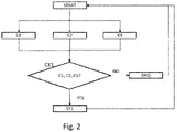
- According to the present invention, the complete release (C2) of the acceleration pedal in dynamic conditions (C1) of the vehicle activates the monitoring of the safety conditions of the vehicle, which expresses an judgment on the need to provide autonomous braking (C3) of the vehicle. The idea of the invention is to provide an autonomous contribution to vehicle braking through the hydraulic transmission HY, temporarily replacing the ordinary strategy of controlling the displacement of the hydraulic motor.
- This contribution is completely independent on the vehicle service brakes activation.
- According to the present invention, the hydraulic motor HM is of the electrohydraulic type, in which its displacement is electrically controlled by the processing unit UCM on board the vehicle.
- The judgment relating the braking need consists, for example, in detecting that the vehicle is traveling down a road.
- The vehicle is equipped with a processing unit UCM configured to receive a signal from the accelerator pedal (or lever) which is 0% at the minimum incline and 100% at the maximum inclination.
- The UCM processing unit is operationally associated with a sensor, for example the phonic wheel, designed to detect the rotation speed of the prime mover "Engine Speed".
- The processing unit is operationally associated with a sensor, for example associated with a drive shaft, to detect a vehicle speed "Vehicle speed".
- The processing unit is configured to detect the occurrence of the following conditions:
- C1 vehicle dynamic conditions, i.e. Vehicle speed > 0,
- C2 complete release of the pedal (or lever), i.e. 0% inclination of the accelerator pedal,
- C3 signal indicating the need to provide autonomous vehicle braking.
- When it appears that all the three previous conditions C1 - C3 are satisfied, then an increase in the displacement of the hydraulic motor is forced up to a predetermined value. The signal indicating the need to provide autonomous vehicle braking includes at least one of:
- the deceleration of the vehicle is less than a predetermined acceleration threshold,
- the vehicle speed exceeds a predetermined speed threshold,
- the vehicle is downhill.
- Therefore, the value of the displacement to which the hydraulic motor is forced can be chosen for example to increase the deceleration of the vehicle beyond a predetermined threshold, or it can be the maximum value of the displacement.
- Therefore, unlike an ordinary strategy for controlling the displacement of the hydraulic motor, the displacement, at the complete release of the accelerator pedal (C2), when the vehicle is in dynamic conditions (C1) and a signal indicates that the vehicle must be braked, displacement of the hydraulic motor is forced to increase obtaining the engine brake typical of vehicles equipped with mechanical transmission, that is, by means of transmission shafts, gears, etc. without a hydrostat.
- Often the prime mover is a Diesel cycle, which offers a good braking effect especially if equipped with a variable geometry turbo compressor.
- According to a preferred variant of the invention, as soon as the accelerator pedal (or lever) is touched, the ordinary operation of the transmission is re-established as described above.
- This preferred variant of the invention is schematized with the help of
Figure 2 , which shows an exemplary flow chart of said variant. - According to a further preferred variant of the invention, shown in
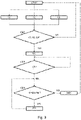
Figure 3 , this ordinary operation is not re-established (immediately) when the accelerator pedal is activated, but only when a relative inclination P% exceeds a predetermined threshold Th2, for example, set at 10%. - In the interval between 0 and Th2, the displacement of the hydraulic motor is reduced proportionally to the inclination of the accelerator pedal up to a predetermined value in Th2. The predetermined value of displacement in Th2 can be
- Predetermined,
- Minimum,
- The displacement value that the ordinary control strategy causes when the accelerator pedal is in Th2, when the strategy is of the "pressure control" type.
- The proportional reduction of the displacement of the hydraulic motor is summarized by step ST2.
- When the displacement value is predetermined or minimum, in the interval between O% and Th2 it can also be envisaged to inhibit the prime mover from receiving the accelerator pedal position signal.
- When the inclination of the accelerator pedal exceeds Th2 up to 100%, the prime mover is controlled as in ordinary conditions ORD, i.e. the rotational speed of the prime mover and therefore the displacement of the hydraulic pump are linearly dependent on the inclination of the accelerator pedal, while the hydraulic motor is controlled with the ordinary control strategy, which is typically in "pressure" or "speed" control. Then, it resumes from the beginning to monitor the occurrence of the three conditions C1, C2, C3.
- It is worth highlighting that the nature of the ordinary control strategy is not relevant for the purposes of the present invention, which is independent of it.
- With reference to
Figure 3 , after the increase in the displacement of the hydraulic motor is forced in ST1, the accelerator pedal fully released condition continues to be checked in a loop, when this condition is no longer verified (CK2 = NO), then it is checked (CK3) whether the relative inclination is between 0% and Th2, in the positive case (CK3 = YES) then the displacement of the hydraulic motor is reduced (ST2) as described above and it resumes checking (CK3) whether its inclination is between 0% and Th2. If not (CK3 = NO), the ordinary strategy of controlling the displacement of the hydraulic motor is restored and it restarts from the beginning (START). - It is worth highlighting that after verification (CK3) if the inclination of the accelerator pedal is between 0% and Th2 a complete new release of the accelerator pedal occurs, being the control dynamics many times faster than the dynamics of the engine displacement control hydraulic, it returns to step ST1 in a transparent way for the driver.
- The present invention can be advantageously realized by means of a computer program, which comprises coding means for carrying out one or more steps of the method, when this program is executed on a computer. Therefore, it is intended that the scope of protection includes said computer program and further computer readable means comprising a recorded message, said computer readable means comprising program coding means for carrying out one or more steps of the method, when said program is run on a computer. Implementation variants of the described non-limiting example are possible, without however departing from the scope of protection of the present invention, including all the equivalent embodiments for a person skilled in the art, to the content of the claims.
- From the above description, the person skilled in the art is able to realize the object of the invention without introducing further construction details.
Claims (12)
- Braking method of an agricultural or work vehicle equipped with a hydraulic transmission (HY) wherein a hydraulic pump (HP) is driven by a prime mover (E) to power a hydraulic motor (HM), wherein the hydraulic motor is operationally connected to at least one vehicle wheel (W), the hydraulic pump having variable displacement with the relative displacement controlled proportionally to the rotation speed (Engine Speed) of the prime mover (E), the hydraulic motor having variable displacement, the method comprising a first step of forcing (ST1) a displacement increase of the hydraulic motor (HM) till to a predetermined value, when, in dynamic conditions (C1) of the vehicle, a relating accelerator pedal is completely released (C2) and a signal (C3) indicating the need to brake the vehicle is present.
- Method according to claim 1, wherein said predetermined value of the displacement is chosen so as to reduce the speed of the vehicle below a predetermined threshold.
- Method according to claim 1, wherein said predetermined displacement value is maximum for said hydraulic motor.
- Method according to any one of claims 1 - 3, wherein said predetermined value of the displacement is achieved by means of a predetermined profile for increasing the displacement.
- Method according to any one of the preceding claims 1 - 4, wherein said signal is generated when- a deceleration of the vehicle is less than a predetermined speed threshold and/or- a vehicle speed exceeds a predetermined speed threshold and/or- the vehicle is downhill.
- Method according to any one of the preceding claims, when the displacement of the hydraulic motor is increased following said first step (ST1), as a result of a pressure on the accelerator pedal, the method comprises a third step (ORD) to restore the ordinary control strategy of the displacement of the hydraulic motor.
- Method according to claim 6, wherein said ordinary control strategy provides that the displacement of the hydraulic motor is inversely proportional to the speed of the vehicle.
- Method according to claim 6 or 7, wherein said restoration is performed when an inclination of the accelerator pedal exceeds a predetermined threshold (Th2).
- Method according to claim 7, wherein, as a consequence of a pressure on the accelerator pedal between a condition of complete release and said predetermined inclination threshold (Th2), the method comprises a second step (ST2) of reducing the displacement of the hydraulic motor, proportionally to the inclination of the accelerator pedal, without restoring the ordinary control strategy of the hydraulic motor.
- Computer program comprising program-coding means suitable for carrying out all steps (ST1, ORD, ST2) of any one of claims 1 to 8, when said program is run on a computer.
- Computer readable means comprising a recorded program, said computer readable means comprising program coding means adapted to perform all steps (ST1, ORD, ST2) of any one of claims 1 to 8, when said program is run on a computer.
- Agricultural or work vehicle equipped with a hydraulic transmission (HY) wherein a hydraulic pump (HP) is driven by a prime mover (E) to power a hydraulic motor (HM), wherein the hydraulic motor is operationally connected with at least a vehicle wheel, the hydraulic pump having a variable displacement, arranged to vary the relative displacement proportionally to the rotation speed (Engine Speed) of the prime mover (E), the hydraulic motor being of electrohydraulic variable displacement, the vehicle further comprising processing means (UCM) configured for forcing (ST1) a displacement increase of the hydraulic motor (HM) till to a predetermined value, when, in dynamic conditions (C1) of the vehicle, a relating accelerator pedal is completely released (C2) and a signal (C3) indicating the need to brake the vehicle is present.
Applications Claiming Priority (1)
| Application Number | Priority Date | Filing Date | Title |
|---|---|---|---|
| IT102020000023857A IT202000023857A1 (en) | 2020-10-09 | 2020-10-09 | METHOD AND SYSTEM OF BRAKING AN AGRICULTURAL OR WORK VEHICLE EQUIPPED WITH HYDRAULIC TRANSMISSION |
Publications (2)
| Publication Number | Publication Date |
|---|---|
| EP3981661A1 true EP3981661A1 (en) | 2022-04-13 |
| EP3981661B1 EP3981661B1 (en) | 2024-12-11 |
Family
ID=73793753
Family Applications (1)
| Application Number | Title | Priority Date | Filing Date |
|---|---|---|---|
| EP21202006.9A Active EP3981661B1 (en) | 2020-10-09 | 2021-10-11 | Braking method and system of an agricultural or work vehicle equipped with a hydraulic transmission |
Country Status (2)
| Country | Link |
|---|---|
| EP (1) | EP3981661B1 (en) |
| IT (1) | IT202000023857A1 (en) |
Citations (2)
| Publication number | Priority date | Publication date | Assignee | Title |
|---|---|---|---|---|
| EP0426443A2 (en) * | 1989-10-31 | 1991-05-08 | Shimadzu Corporation | Engine-brake controller for vehicle with stepless speed-changer |
| EP2119943A2 (en) * | 2008-05-13 | 2009-11-18 | Kobelco Cranes Co., Ltd. | Control apparatus for hydraulic driving vehicle |
-
2020
- 2020-10-09 IT IT102020000023857A patent/IT202000023857A1/en unknown
-
2021
- 2021-10-11 EP EP21202006.9A patent/EP3981661B1/en active Active
Patent Citations (2)
| Publication number | Priority date | Publication date | Assignee | Title |
|---|---|---|---|---|
| EP0426443A2 (en) * | 1989-10-31 | 1991-05-08 | Shimadzu Corporation | Engine-brake controller for vehicle with stepless speed-changer |
| EP2119943A2 (en) * | 2008-05-13 | 2009-11-18 | Kobelco Cranes Co., Ltd. | Control apparatus for hydraulic driving vehicle |
Also Published As
| Publication number | Publication date |
|---|---|
| IT202000023857A1 (en) | 2022-04-09 |
| EP3981661B1 (en) | 2024-12-11 |
Similar Documents
| Publication | Publication Date | Title |
|---|---|---|
| JP7526248B2 (en) | SYSTEM AND METHOD FOR CONTROLLING A VEHICLE - Patent application | |
| US11491880B2 (en) | System and method for controlling a vehicle | |
| US10576950B2 (en) | Method and a system for controlling vehicle speed | |
| US12140163B2 (en) | Hydraulic braking energy utilization for emergency steering, braking, charging accumulator(s), and/or work functions to reduce or prevent engine from overspeed, assist acceleration and/or unlimited towing | |
| US11001261B2 (en) | Method and a system for controlling a vehicle during a downhill start | |
| JP2019536403A5 (en) | ||
| JPH0672297A (en) | Control method for automatic braking device | |
| EP3006283A1 (en) | Vehicle brake arrangement | |
| US9096231B2 (en) | Rollback prevention system for mobile machine | |
| EP4328100B1 (en) | Emergency brake method and system | |
| EP3981661B1 (en) | Braking method and system of an agricultural or work vehicle equipped with a hydraulic transmission | |
| US20130256052A1 (en) | Rollback prevention system for mobile machine | |
| US10166990B2 (en) | Vehicle | |
| JP2005105894A (en) | Automatic engine stop device for vehicle | |
| JP3070451B2 (en) | Braking energy regeneration device | |
| JP7058047B2 (en) | Vehicle braking device and vehicle braking method | |
| KR20190069778A (en) | Method for using auxiliary brake in emergency braking | |
| JP2970356B2 (en) | Braking energy regeneration device | |
| EP4299953A1 (en) | Method and control system of a hydraulic transmission of a work or agricultural vehicle | |
| JP3158235B2 (en) | Accumulation type braking energy regeneration device for vehicles | |
| JP3621448B2 (en) | Accumulated braking energy regeneration device for vehicle | |
| US20240343236A1 (en) | Controller and control method | |
| EP2621779B1 (en) | Method for the automatic braking of a motor vehicle | |
| CN121448397A (en) | Limit working condition control method, vehicle and storage medium | |
| JPH0840105A (en) | Vehicle energy regeneration device |
Legal Events
| Date | Code | Title | Description |
|---|---|---|---|
| PUAI | Public reference made under article 153(3) epc to a published international application that has entered the european phase |
Free format text: ORIGINAL CODE: 0009012 |
|
| STAA | Information on the status of an ep patent application or granted ep patent |
Free format text: STATUS: THE APPLICATION HAS BEEN PUBLISHED |
|
| AK | Designated contracting states |
Kind code of ref document: A1 Designated state(s): AL AT BE BG CH CY CZ DE DK EE ES FI FR GB GR HR HU IE IS IT LI LT LU LV MC MK MT NL NO PL PT RO RS SE SI SK SM TR |
|
| STAA | Information on the status of an ep patent application or granted ep patent |
Free format text: STATUS: REQUEST FOR EXAMINATION WAS MADE |
|
| 17P | Request for examination filed |
Effective date: 20221013 |
|
| RBV | Designated contracting states (corrected) |
Designated state(s): AL AT BE BG CH CY CZ DE DK EE ES FI FR GB GR HR HU IE IS IT LI LT LU LV MC MK MT NL NO PL PT RO RS SE SI SK SM TR |
|
| RAP3 | Party data changed (applicant data changed or rights of an application transferred) |
Owner name: CNH INDUSTRIAL ITALIA S.P.A. |
|
| STAA | Information on the status of an ep patent application or granted ep patent |
Free format text: STATUS: EXAMINATION IS IN PROGRESS |
|
| 17Q | First examination report despatched |
Effective date: 20230720 |
|
| GRAP | Despatch of communication of intention to grant a patent |
Free format text: ORIGINAL CODE: EPIDOSNIGR1 |
|
| STAA | Information on the status of an ep patent application or granted ep patent |
Free format text: STATUS: GRANT OF PATENT IS INTENDED |
|
| INTG | Intention to grant announced |
Effective date: 20240508 |
|
| GRAS | Grant fee paid |
Free format text: ORIGINAL CODE: EPIDOSNIGR3 |
|
| GRAA | (expected) grant |
Free format text: ORIGINAL CODE: 0009210 |
|
| STAA | Information on the status of an ep patent application or granted ep patent |
Free format text: STATUS: THE PATENT HAS BEEN GRANTED |
|
| AK | Designated contracting states |
Kind code of ref document: B1 Designated state(s): AL AT BE BG CH CY CZ DE DK EE ES FI FR GB GR HR HU IE IS IT LI LT LU LV MC MK MT NL NO PL PT RO RS SE SI SK SM TR |
|
| REG | Reference to a national code |
Ref country code: GB Ref legal event code: FG4D |
|
| REG | Reference to a national code |
Ref country code: CH Ref legal event code: EP |
|
| REG | Reference to a national code |
Ref country code: IE Ref legal event code: FG4D |
|
| REG | Reference to a national code |
Ref country code: DE Ref legal event code: R096 Ref document number: 602021023185 Country of ref document: DE |
|
| REG | Reference to a national code |
Ref country code: LT Ref legal event code: MG9D |
|
| PG25 | Lapsed in a contracting state [announced via postgrant information from national office to epo] |
Ref country code: HR Free format text: LAPSE BECAUSE OF FAILURE TO SUBMIT A TRANSLATION OF THE DESCRIPTION OR TO PAY THE FEE WITHIN THE PRESCRIBED TIME-LIMIT Effective date: 20241211 |
|
| PG25 | Lapsed in a contracting state [announced via postgrant information from national office to epo] |
Ref country code: FI Free format text: LAPSE BECAUSE OF FAILURE TO SUBMIT A TRANSLATION OF THE DESCRIPTION OR TO PAY THE FEE WITHIN THE PRESCRIBED TIME-LIMIT Effective date: 20241211 |
|
| PG25 | Lapsed in a contracting state [announced via postgrant information from national office to epo] |
Ref country code: BG Free format text: LAPSE BECAUSE OF FAILURE TO SUBMIT A TRANSLATION OF THE DESCRIPTION OR TO PAY THE FEE WITHIN THE PRESCRIBED TIME-LIMIT Effective date: 20241211 |
|
| REG | Reference to a national code |
Ref country code: NL Ref legal event code: MP Effective date: 20241211 |
|
| PG25 | Lapsed in a contracting state [announced via postgrant information from national office to epo] |
Ref country code: ES Free format text: LAPSE BECAUSE OF FAILURE TO SUBMIT A TRANSLATION OF THE DESCRIPTION OR TO PAY THE FEE WITHIN THE PRESCRIBED TIME-LIMIT Effective date: 20241211 |
|
| PG25 | Lapsed in a contracting state [announced via postgrant information from national office to epo] |
Ref country code: NO Free format text: LAPSE BECAUSE OF FAILURE TO SUBMIT A TRANSLATION OF THE DESCRIPTION OR TO PAY THE FEE WITHIN THE PRESCRIBED TIME-LIMIT Effective date: 20250311 |
|
| PG25 | Lapsed in a contracting state [announced via postgrant information from national office to epo] |
Ref country code: GR Free format text: LAPSE BECAUSE OF FAILURE TO SUBMIT A TRANSLATION OF THE DESCRIPTION OR TO PAY THE FEE WITHIN THE PRESCRIBED TIME-LIMIT Effective date: 20250312 Ref country code: LV Free format text: LAPSE BECAUSE OF FAILURE TO SUBMIT A TRANSLATION OF THE DESCRIPTION OR TO PAY THE FEE WITHIN THE PRESCRIBED TIME-LIMIT Effective date: 20241211 |
|
| PG25 | Lapsed in a contracting state [announced via postgrant information from national office to epo] |
Ref country code: RS Free format text: LAPSE BECAUSE OF FAILURE TO SUBMIT A TRANSLATION OF THE DESCRIPTION OR TO PAY THE FEE WITHIN THE PRESCRIBED TIME-LIMIT Effective date: 20250311 |
|
| PG25 | Lapsed in a contracting state [announced via postgrant information from national office to epo] |
Ref country code: NL Free format text: LAPSE BECAUSE OF FAILURE TO SUBMIT A TRANSLATION OF THE DESCRIPTION OR TO PAY THE FEE WITHIN THE PRESCRIBED TIME-LIMIT Effective date: 20241211 |
|
| REG | Reference to a national code |
Ref country code: AT Ref legal event code: MK05 Ref document number: 1750179 Country of ref document: AT Kind code of ref document: T Effective date: 20241211 |
|
| PG25 | Lapsed in a contracting state [announced via postgrant information from national office to epo] |
Ref country code: SM Free format text: LAPSE BECAUSE OF FAILURE TO SUBMIT A TRANSLATION OF THE DESCRIPTION OR TO PAY THE FEE WITHIN THE PRESCRIBED TIME-LIMIT Effective date: 20241211 |
|
| PG25 | Lapsed in a contracting state [announced via postgrant information from national office to epo] |
Ref country code: PL Free format text: LAPSE BECAUSE OF FAILURE TO SUBMIT A TRANSLATION OF THE DESCRIPTION OR TO PAY THE FEE WITHIN THE PRESCRIBED TIME-LIMIT Effective date: 20241211 |
|
| PG25 | Lapsed in a contracting state [announced via postgrant information from national office to epo] |
Ref country code: IS Free format text: LAPSE BECAUSE OF FAILURE TO SUBMIT A TRANSLATION OF THE DESCRIPTION OR TO PAY THE FEE WITHIN THE PRESCRIBED TIME-LIMIT Effective date: 20250411 |
|
| PG25 | Lapsed in a contracting state [announced via postgrant information from national office to epo] |
Ref country code: PT Free format text: LAPSE BECAUSE OF FAILURE TO SUBMIT A TRANSLATION OF THE DESCRIPTION OR TO PAY THE FEE WITHIN THE PRESCRIBED TIME-LIMIT Effective date: 20250411 |
|
| PG25 | Lapsed in a contracting state [announced via postgrant information from national office to epo] |
Ref country code: EE Free format text: LAPSE BECAUSE OF FAILURE TO SUBMIT A TRANSLATION OF THE DESCRIPTION OR TO PAY THE FEE WITHIN THE PRESCRIBED TIME-LIMIT Effective date: 20241211 |
|
| PG25 | Lapsed in a contracting state [announced via postgrant information from national office to epo] |
Ref country code: AT Free format text: LAPSE BECAUSE OF FAILURE TO SUBMIT A TRANSLATION OF THE DESCRIPTION OR TO PAY THE FEE WITHIN THE PRESCRIBED TIME-LIMIT Effective date: 20241211 Ref country code: RO Free format text: LAPSE BECAUSE OF FAILURE TO SUBMIT A TRANSLATION OF THE DESCRIPTION OR TO PAY THE FEE WITHIN THE PRESCRIBED TIME-LIMIT Effective date: 20241211 |
|
| PG25 | Lapsed in a contracting state [announced via postgrant information from national office to epo] |
Ref country code: SK Free format text: LAPSE BECAUSE OF FAILURE TO SUBMIT A TRANSLATION OF THE DESCRIPTION OR TO PAY THE FEE WITHIN THE PRESCRIBED TIME-LIMIT Effective date: 20241211 |
|
| PG25 | Lapsed in a contracting state [announced via postgrant information from national office to epo] |
Ref country code: CZ Free format text: LAPSE BECAUSE OF FAILURE TO SUBMIT A TRANSLATION OF THE DESCRIPTION OR TO PAY THE FEE WITHIN THE PRESCRIBED TIME-LIMIT Effective date: 20241211 |
|
| PG25 | Lapsed in a contracting state [announced via postgrant information from national office to epo] |
Ref country code: SE Free format text: LAPSE BECAUSE OF FAILURE TO SUBMIT A TRANSLATION OF THE DESCRIPTION OR TO PAY THE FEE WITHIN THE PRESCRIBED TIME-LIMIT Effective date: 20241211 |
|
| REG | Reference to a national code |
Ref country code: DE Ref legal event code: R097 Ref document number: 602021023185 Country of ref document: DE |
|
| PG25 | Lapsed in a contracting state [announced via postgrant information from national office to epo] |
Ref country code: DK Free format text: LAPSE BECAUSE OF FAILURE TO SUBMIT A TRANSLATION OF THE DESCRIPTION OR TO PAY THE FEE WITHIN THE PRESCRIBED TIME-LIMIT Effective date: 20241211 |
|
| PLBE | No opposition filed within time limit |
Free format text: ORIGINAL CODE: 0009261 |
|
| STAA | Information on the status of an ep patent application or granted ep patent |
Free format text: STATUS: NO OPPOSITION FILED WITHIN TIME LIMIT |
|
| REG | Reference to a national code |
Ref country code: CH Ref legal event code: L10 Free format text: ST27 STATUS EVENT CODE: U-0-0-L10-L00 (AS PROVIDED BY THE NATIONAL OFFICE) Effective date: 20251022 |
|
| 26N | No opposition filed |
Effective date: 20250912 |
|
| PGFP | Annual fee paid to national office [announced via postgrant information from national office to epo] |
Ref country code: DE Payment date: 20251028 Year of fee payment: 5 |
|
| PGFP | Annual fee paid to national office [announced via postgrant information from national office to epo] |
Ref country code: GB Payment date: 20251021 Year of fee payment: 5 |
|
| PGFP | Annual fee paid to national office [announced via postgrant information from national office to epo] |
Ref country code: IT Payment date: 20251024 Year of fee payment: 5 |
|
| PGFP | Annual fee paid to national office [announced via postgrant information from national office to epo] |
Ref country code: FR Payment date: 20251027 Year of fee payment: 5 |
|
| REG | Reference to a national code |
Ref country code: CH Ref legal event code: H13 Free format text: ST27 STATUS EVENT CODE: U-0-0-H10-H13 (AS PROVIDED BY THE NATIONAL OFFICE) Effective date: 20260527 |
|
| PG25 | Lapsed in a contracting state [announced via postgrant information from national office to epo] |
Ref country code: LU Free format text: LAPSE BECAUSE OF NON-PAYMENT OF DUE FEES Effective date: 20251011 |
|
| REG | Reference to a national code |
Ref country code: BE Ref legal event code: MM Effective date: 20251031 |
|
| PG25 | Lapsed in a contracting state [announced via postgrant information from national office to epo] |
Ref country code: LT Free format text: LAPSE BECAUSE OF FAILURE TO SUBMIT A TRANSLATION OF THE DESCRIPTION OR TO PAY THE FEE WITHIN THE PRESCRIBED TIME-LIMIT Effective date: 20241211 |
|
| PG25 | Lapsed in a contracting state [announced via postgrant information from national office to epo] |
Ref country code: MC Free format text: LAPSE BECAUSE OF FAILURE TO SUBMIT A TRANSLATION OF THE DESCRIPTION OR TO PAY THE FEE WITHIN THE PRESCRIBED TIME-LIMIT Effective date: 20241211 |
|
| PG25 | Lapsed in a contracting state [announced via postgrant information from national office to epo] |
Ref country code: BE Free format text: LAPSE BECAUSE OF NON-PAYMENT OF DUE FEES Effective date: 20251031 Ref country code: CH Free format text: LAPSE BECAUSE OF NON-PAYMENT OF DUE FEES Effective date: 20251031 |