EP3981638A2 - Apparatus and method for charging an electric vehicle - Google Patents
Apparatus and method for charging an electric vehicle Download PDFInfo
- Publication number
- EP3981638A2 EP3981638A2 EP21191611.9A EP21191611A EP3981638A2 EP 3981638 A2 EP3981638 A2 EP 3981638A2 EP 21191611 A EP21191611 A EP 21191611A EP 3981638 A2 EP3981638 A2 EP 3981638A2
- Authority
- EP
- European Patent Office
- Prior art keywords
- energy
- esms
- port
- voltage
- energy storage
- Prior art date
- Legal status (The legal status is an assumption and is not a legal conclusion. Google has not performed a legal analysis and makes no representation as to the accuracy of the status listed.)
- Granted
Links
Images


Classifications
-
- B—PERFORMING OPERATIONS; TRANSPORTING
- B60—VEHICLES IN GENERAL
- B60L—PROPULSION OF ELECTRICALLY-PROPELLED VEHICLES; SUPPLYING ELECTRIC POWER FOR AUXILIARY EQUIPMENT OF ELECTRICALLY-PROPELLED VEHICLES; ELECTRODYNAMIC BRAKE SYSTEMS FOR VEHICLES IN GENERAL; MAGNETIC SUSPENSION OR LEVITATION FOR VEHICLES; MONITORING OPERATING VARIABLES OF ELECTRICALLY-PROPELLED VEHICLES; ELECTRIC SAFETY DEVICES FOR ELECTRICALLY-PROPELLED VEHICLES
- B60L58/00—Methods or circuit arrangements for monitoring or controlling batteries or fuel cells, specially adapted for electric vehicles
- B60L58/10—Methods or circuit arrangements for monitoring or controlling batteries or fuel cells, specially adapted for electric vehicles for monitoring or controlling batteries
- B60L58/18—Methods or circuit arrangements for monitoring or controlling batteries or fuel cells, specially adapted for electric vehicles for monitoring or controlling batteries of two or more battery modules
- B60L58/20—Methods or circuit arrangements for monitoring or controlling batteries or fuel cells, specially adapted for electric vehicles for monitoring or controlling batteries of two or more battery modules having different nominal voltages
-
- B—PERFORMING OPERATIONS; TRANSPORTING
- B60—VEHICLES IN GENERAL
- B60L—PROPULSION OF ELECTRICALLY-PROPELLED VEHICLES; SUPPLYING ELECTRIC POWER FOR AUXILIARY EQUIPMENT OF ELECTRICALLY-PROPELLED VEHICLES; ELECTRODYNAMIC BRAKE SYSTEMS FOR VEHICLES IN GENERAL; MAGNETIC SUSPENSION OR LEVITATION FOR VEHICLES; MONITORING OPERATING VARIABLES OF ELECTRICALLY-PROPELLED VEHICLES; ELECTRIC SAFETY DEVICES FOR ELECTRICALLY-PROPELLED VEHICLES
- B60L50/00—Electric propulsion with power supplied within the vehicle
- B60L50/10—Electric propulsion with power supplied within the vehicle using propulsion power supplied by engine-driven generators, e.g. generators driven by combustion engines
- B60L50/16—Electric propulsion with power supplied within the vehicle using propulsion power supplied by engine-driven generators, e.g. generators driven by combustion engines with provision for separate direct mechanical propulsion
-
- B—PERFORMING OPERATIONS; TRANSPORTING
- B60—VEHICLES IN GENERAL
- B60L—PROPULSION OF ELECTRICALLY-PROPELLED VEHICLES; SUPPLYING ELECTRIC POWER FOR AUXILIARY EQUIPMENT OF ELECTRICALLY-PROPELLED VEHICLES; ELECTRODYNAMIC BRAKE SYSTEMS FOR VEHICLES IN GENERAL; MAGNETIC SUSPENSION OR LEVITATION FOR VEHICLES; MONITORING OPERATING VARIABLES OF ELECTRICALLY-PROPELLED VEHICLES; ELECTRIC SAFETY DEVICES FOR ELECTRICALLY-PROPELLED VEHICLES
- B60L50/00—Electric propulsion with power supplied within the vehicle
- B60L50/40—Electric propulsion with power supplied within the vehicle using propulsion power supplied by capacitors
-
- B—PERFORMING OPERATIONS; TRANSPORTING
- B60—VEHICLES IN GENERAL
- B60L—PROPULSION OF ELECTRICALLY-PROPELLED VEHICLES; SUPPLYING ELECTRIC POWER FOR AUXILIARY EQUIPMENT OF ELECTRICALLY-PROPELLED VEHICLES; ELECTRODYNAMIC BRAKE SYSTEMS FOR VEHICLES IN GENERAL; MAGNETIC SUSPENSION OR LEVITATION FOR VEHICLES; MONITORING OPERATING VARIABLES OF ELECTRICALLY-PROPELLED VEHICLES; ELECTRIC SAFETY DEVICES FOR ELECTRICALLY-PROPELLED VEHICLES
- B60L53/00—Methods of charging batteries, specially adapted for electric vehicles; Charging stations or on-board charging equipment therefor; Exchange of energy storage elements in electric vehicles
- B60L53/20—Methods of charging batteries, specially adapted for electric vehicles; Charging stations or on-board charging equipment therefor; Exchange of energy storage elements in electric vehicles characterised by converters located in the vehicle
- B60L53/22—Constructional details or arrangements of charging converters specially adapted for charging electric vehicles
-
- B—PERFORMING OPERATIONS; TRANSPORTING
- B60—VEHICLES IN GENERAL
- B60L—PROPULSION OF ELECTRICALLY-PROPELLED VEHICLES; SUPPLYING ELECTRIC POWER FOR AUXILIARY EQUIPMENT OF ELECTRICALLY-PROPELLED VEHICLES; ELECTRODYNAMIC BRAKE SYSTEMS FOR VEHICLES IN GENERAL; MAGNETIC SUSPENSION OR LEVITATION FOR VEHICLES; MONITORING OPERATING VARIABLES OF ELECTRICALLY-PROPELLED VEHICLES; ELECTRIC SAFETY DEVICES FOR ELECTRICALLY-PROPELLED VEHICLES
- B60L58/00—Methods or circuit arrangements for monitoring or controlling batteries or fuel cells, specially adapted for electric vehicles
- B60L58/10—Methods or circuit arrangements for monitoring or controlling batteries or fuel cells, specially adapted for electric vehicles for monitoring or controlling batteries
- B60L58/12—Methods or circuit arrangements for monitoring or controlling batteries or fuel cells, specially adapted for electric vehicles for monitoring or controlling batteries responding to state of charge [SoC]
- B60L58/13—Maintaining the SoC within a determined range
-
- B—PERFORMING OPERATIONS; TRANSPORTING
- B60—VEHICLES IN GENERAL
- B60L—PROPULSION OF ELECTRICALLY-PROPELLED VEHICLES; SUPPLYING ELECTRIC POWER FOR AUXILIARY EQUIPMENT OF ELECTRICALLY-PROPELLED VEHICLES; ELECTRODYNAMIC BRAKE SYSTEMS FOR VEHICLES IN GENERAL; MAGNETIC SUSPENSION OR LEVITATION FOR VEHICLES; MONITORING OPERATING VARIABLES OF ELECTRICALLY-PROPELLED VEHICLES; ELECTRIC SAFETY DEVICES FOR ELECTRICALLY-PROPELLED VEHICLES
- B60L2210/00—Converter types
- B60L2210/10—DC to DC converters
- B60L2210/12—Buck converters
-
- B—PERFORMING OPERATIONS; TRANSPORTING
- B60—VEHICLES IN GENERAL
- B60L—PROPULSION OF ELECTRICALLY-PROPELLED VEHICLES; SUPPLYING ELECTRIC POWER FOR AUXILIARY EQUIPMENT OF ELECTRICALLY-PROPELLED VEHICLES; ELECTRODYNAMIC BRAKE SYSTEMS FOR VEHICLES IN GENERAL; MAGNETIC SUSPENSION OR LEVITATION FOR VEHICLES; MONITORING OPERATING VARIABLES OF ELECTRICALLY-PROPELLED VEHICLES; ELECTRIC SAFETY DEVICES FOR ELECTRICALLY-PROPELLED VEHICLES
- B60L2210/00—Converter types
- B60L2210/10—DC to DC converters
- B60L2210/14—Boost converters
-
- B—PERFORMING OPERATIONS; TRANSPORTING
- B60—VEHICLES IN GENERAL
- B60L—PROPULSION OF ELECTRICALLY-PROPELLED VEHICLES; SUPPLYING ELECTRIC POWER FOR AUXILIARY EQUIPMENT OF ELECTRICALLY-PROPELLED VEHICLES; ELECTRODYNAMIC BRAKE SYSTEMS FOR VEHICLES IN GENERAL; MAGNETIC SUSPENSION OR LEVITATION FOR VEHICLES; MONITORING OPERATING VARIABLES OF ELECTRICALLY-PROPELLED VEHICLES; ELECTRIC SAFETY DEVICES FOR ELECTRICALLY-PROPELLED VEHICLES
- B60L2210/00—Converter types
- B60L2210/30—AC to DC converters
-
- B—PERFORMING OPERATIONS; TRANSPORTING
- B60—VEHICLES IN GENERAL
- B60L—PROPULSION OF ELECTRICALLY-PROPELLED VEHICLES; SUPPLYING ELECTRIC POWER FOR AUXILIARY EQUIPMENT OF ELECTRICALLY-PROPELLED VEHICLES; ELECTRODYNAMIC BRAKE SYSTEMS FOR VEHICLES IN GENERAL; MAGNETIC SUSPENSION OR LEVITATION FOR VEHICLES; MONITORING OPERATING VARIABLES OF ELECTRICALLY-PROPELLED VEHICLES; ELECTRIC SAFETY DEVICES FOR ELECTRICALLY-PROPELLED VEHICLES
- B60L2210/00—Converter types
- B60L2210/40—DC to AC converters
-
- B—PERFORMING OPERATIONS; TRANSPORTING
- B60—VEHICLES IN GENERAL
- B60L—PROPULSION OF ELECTRICALLY-PROPELLED VEHICLES; SUPPLYING ELECTRIC POWER FOR AUXILIARY EQUIPMENT OF ELECTRICALLY-PROPELLED VEHICLES; ELECTRODYNAMIC BRAKE SYSTEMS FOR VEHICLES IN GENERAL; MAGNETIC SUSPENSION OR LEVITATION FOR VEHICLES; MONITORING OPERATING VARIABLES OF ELECTRICALLY-PROPELLED VEHICLES; ELECTRIC SAFETY DEVICES FOR ELECTRICALLY-PROPELLED VEHICLES
- B60L2240/00—Control parameters of input or output; Target parameters
- B60L2240/40—Drive Train control parameters
- B60L2240/44—Drive Train control parameters related to combustion engines
- B60L2240/441—Speed
-
- B—PERFORMING OPERATIONS; TRANSPORTING
- B60—VEHICLES IN GENERAL
- B60L—PROPULSION OF ELECTRICALLY-PROPELLED VEHICLES; SUPPLYING ELECTRIC POWER FOR AUXILIARY EQUIPMENT OF ELECTRICALLY-PROPELLED VEHICLES; ELECTRODYNAMIC BRAKE SYSTEMS FOR VEHICLES IN GENERAL; MAGNETIC SUSPENSION OR LEVITATION FOR VEHICLES; MONITORING OPERATING VARIABLES OF ELECTRICALLY-PROPELLED VEHICLES; ELECTRIC SAFETY DEVICES FOR ELECTRICALLY-PROPELLED VEHICLES
- B60L2240/00—Control parameters of input or output; Target parameters
- B60L2240/40—Drive Train control parameters
- B60L2240/44—Drive Train control parameters related to combustion engines
- B60L2240/445—Temperature
-
- B—PERFORMING OPERATIONS; TRANSPORTING
- B60—VEHICLES IN GENERAL
- B60L—PROPULSION OF ELECTRICALLY-PROPELLED VEHICLES; SUPPLYING ELECTRIC POWER FOR AUXILIARY EQUIPMENT OF ELECTRICALLY-PROPELLED VEHICLES; ELECTRODYNAMIC BRAKE SYSTEMS FOR VEHICLES IN GENERAL; MAGNETIC SUSPENSION OR LEVITATION FOR VEHICLES; MONITORING OPERATING VARIABLES OF ELECTRICALLY-PROPELLED VEHICLES; ELECTRIC SAFETY DEVICES FOR ELECTRICALLY-PROPELLED VEHICLES
- B60L2270/00—Problem solutions or means not otherwise provided for
- B60L2270/20—Inrush current reduction, i.e. avoiding high currents when connecting the battery
-
- Y—GENERAL TAGGING OF NEW TECHNOLOGICAL DEVELOPMENTS; GENERAL TAGGING OF CROSS-SECTIONAL TECHNOLOGIES SPANNING OVER SEVERAL SECTIONS OF THE IPC; TECHNICAL SUBJECTS COVERED BY FORMER USPC CROSS-REFERENCE ART COLLECTIONS [XRACs] AND DIGESTS
- Y02—TECHNOLOGIES OR APPLICATIONS FOR MITIGATION OR ADAPTATION AGAINST CLIMATE CHANGE
- Y02T—CLIMATE CHANGE MITIGATION TECHNOLOGIES RELATED TO TRANSPORTATION
- Y02T10/00—Road transport of goods or passengers
- Y02T10/60—Other road transportation technologies with climate change mitigation effect
- Y02T10/62—Hybrid vehicles
-
- Y—GENERAL TAGGING OF NEW TECHNOLOGICAL DEVELOPMENTS; GENERAL TAGGING OF CROSS-SECTIONAL TECHNOLOGIES SPANNING OVER SEVERAL SECTIONS OF THE IPC; TECHNICAL SUBJECTS COVERED BY FORMER USPC CROSS-REFERENCE ART COLLECTIONS [XRACs] AND DIGESTS
- Y02—TECHNOLOGIES OR APPLICATIONS FOR MITIGATION OR ADAPTATION AGAINST CLIMATE CHANGE
- Y02T—CLIMATE CHANGE MITIGATION TECHNOLOGIES RELATED TO TRANSPORTATION
- Y02T10/00—Road transport of goods or passengers
- Y02T10/60—Other road transportation technologies with climate change mitigation effect
- Y02T10/70—Energy storage systems for electromobility, e.g. batteries
-
- Y—GENERAL TAGGING OF NEW TECHNOLOGICAL DEVELOPMENTS; GENERAL TAGGING OF CROSS-SECTIONAL TECHNOLOGIES SPANNING OVER SEVERAL SECTIONS OF THE IPC; TECHNICAL SUBJECTS COVERED BY FORMER USPC CROSS-REFERENCE ART COLLECTIONS [XRACs] AND DIGESTS
- Y02—TECHNOLOGIES OR APPLICATIONS FOR MITIGATION OR ADAPTATION AGAINST CLIMATE CHANGE
- Y02T—CLIMATE CHANGE MITIGATION TECHNOLOGIES RELATED TO TRANSPORTATION
- Y02T10/00—Road transport of goods or passengers
- Y02T10/60—Other road transportation technologies with climate change mitigation effect
- Y02T10/7072—Electromobility specific charging systems or methods for batteries, ultracapacitors, supercapacitors or double-layer capacitors
-
- Y—GENERAL TAGGING OF NEW TECHNOLOGICAL DEVELOPMENTS; GENERAL TAGGING OF CROSS-SECTIONAL TECHNOLOGIES SPANNING OVER SEVERAL SECTIONS OF THE IPC; TECHNICAL SUBJECTS COVERED BY FORMER USPC CROSS-REFERENCE ART COLLECTIONS [XRACs] AND DIGESTS
- Y02—TECHNOLOGIES OR APPLICATIONS FOR MITIGATION OR ADAPTATION AGAINST CLIMATE CHANGE
- Y02T—CLIMATE CHANGE MITIGATION TECHNOLOGIES RELATED TO TRANSPORTATION
- Y02T10/00—Road transport of goods or passengers
- Y02T10/60—Other road transportation technologies with climate change mitigation effect
- Y02T10/72—Electric energy management in electromobility
-
- Y—GENERAL TAGGING OF NEW TECHNOLOGICAL DEVELOPMENTS; GENERAL TAGGING OF CROSS-SECTIONAL TECHNOLOGIES SPANNING OVER SEVERAL SECTIONS OF THE IPC; TECHNICAL SUBJECTS COVERED BY FORMER USPC CROSS-REFERENCE ART COLLECTIONS [XRACs] AND DIGESTS
- Y02—TECHNOLOGIES OR APPLICATIONS FOR MITIGATION OR ADAPTATION AGAINST CLIMATE CHANGE
- Y02T—CLIMATE CHANGE MITIGATION TECHNOLOGIES RELATED TO TRANSPORTATION
- Y02T90/00—Enabling technologies or technologies with a potential or indirect contribution to GHG emissions mitigation
- Y02T90/10—Technologies relating to charging of electric vehicles
- Y02T90/12—Electric charging stations
-
- Y—GENERAL TAGGING OF NEW TECHNOLOGICAL DEVELOPMENTS; GENERAL TAGGING OF CROSS-SECTIONAL TECHNOLOGIES SPANNING OVER SEVERAL SECTIONS OF THE IPC; TECHNICAL SUBJECTS COVERED BY FORMER USPC CROSS-REFERENCE ART COLLECTIONS [XRACs] AND DIGESTS
- Y02—TECHNOLOGIES OR APPLICATIONS FOR MITIGATION OR ADAPTATION AGAINST CLIMATE CHANGE
- Y02T—CLIMATE CHANGE MITIGATION TECHNOLOGIES RELATED TO TRANSPORTATION
- Y02T90/00—Enabling technologies or technologies with a potential or indirect contribution to GHG emissions mitigation
- Y02T90/10—Technologies relating to charging of electric vehicles
- Y02T90/14—Plug-in electric vehicles
Definitions
- Embodiments of the invention relate generally to electric drive systems including hybrid and electric vehicles and, more particularly, to charging an electric vehicle using a multiport energy management system.
- Hybrid electric vehicles may combine an internal combustion engine and an electric motor powered by an energy storage device, such as a traction battery, to propel the vehicle. Such a combination may increase overall fuel efficiency by enabling the combustion engine and the electric motor to each operate in respective ranges of increased efficiency.
- Electric motors for example, may be efficient at accelerating from a standing start, while internal combustion engines (ICEs) may be efficient during sustained periods of constant engine operation, such as in highway driving. Having an electric motor to boost initial acceleration allows combustion engines in hybrid vehicles to be smaller and more fuel efficient.
- Purely electric vehicles use stored electrical energy to power an electric motor, which propels the vehicle and may also operate auxiliary drives.
- Purely electric vehicles may use one or more sources of stored electrical energy.
- a first source of stored electrical energy may be used to provide longer-lasting energy (such as a low-voltage battery) while a second source of stored electrical energy may be used to provide higher-power energy for, for example, acceleration (such as a high-voltage battery or an ultracapacitor).
- Plug-in electric vehicles are configured to use electrical energy from an external source to recharge the energy storage devices.
- Such vehicles may include on-road and off-road vehicles, golf carts, neighborhood electric vehicles, forklifts, and utility trucks as examples. These vehicles may use either off-board stationary battery chargers, on-board battery chargers, or a combination of off-board stationary battery chargers and on-board battery chargers to transfer electrical energy from a utility grid or renewable energy source to the vehicle's on-board traction battery.
- Plug-in vehicles may include circuitry and connections to facilitate the recharging of the traction battery from the utility grid or other external source, for example.
- EVs battery chargers are important components in the development of electric vehicles (EVs). Historically, two types of chargers for EV application are known. One is a standalone type where functionality and style can be compared to a gas station to perform rapid charging. The other is an on-board type, which would be used for slower C-rate charging from a conventional household outlet.
- EVs typically include energy storage devices such as low voltage batteries (for range and cruising, for example), high voltage batteries (for boost and acceleration, for example), and ultracapacitors (for boost and acceleration, for example), to name a few. Because these energy storage devices operate under different voltages and are charged differently from one another, typically each storage device includes its own unique charging system. This can lead to multiple components and charging systems because the storage devices typically cannot be charged using charging systems for other storage devices. In other words, a charging device used to charge a low-voltage battery typically cannot be used to charge an ultracapacitor or a high-voltage battery.
- each charger type accordingly includes a system of electrical components, reliability of the overall system may be compromised because of the large number of components that may be used in order to provide this functionality. And, although the electric and electronic components can be sized such that electrical stress levels are low, the relatively high on-duty cycle can influence the reliability significantly, as well.
- an energy storage management system includes one or more energy storage devices coupled to a drivetrain and configured to store DC energy, a power electronic conversion system having a plurality of energy ports, the power electronic conversion system comprising a plurality of DC electrical converters, each DC electrical converter configured to step up and to step down a DC voltage, wherein each of the plurality of energy ports is coupleable to each of the one or more energy storage devices and each of the plurality of energy ports is coupleable to an electrical charging system.
- the EV includes a controller configured to determine a voltage of each energy port having either an energy storage device or a DC electrical charging system coupled thereto, and electrically connect a first energy port to a second energy port of at least two of the energy ports such that at least one of the DC electrical converters either steps up or steps down an input DC voltage based on the determined voltage of each energy port.
- a method of fabricating an energy storage and management system includes coupling one or more energy storage devices to a vehicle powertrain, fabricating a charging device having a plurality of buck-boost converters, attaching the charging device to the vehicle, the charging device comprising a plurality of energy ports, each of the plurality of energy ports coupleable to each of the one or more energy storage devices, sensing a voltage across each of the plurality of energy ports, determining if an energy storage device and an electrical charging system is coupled to any of the plurality of energy ports based on the sensed voltage, and electrically connecting the electrical charging system to any of the plurality of energy ports having an energy storage device by selectively directing electrical current to flow through one or more of the plurality of buck-boost converters.
- ESMS energy storage and management system
- a non-transitory computer readable storage medium positioned on an energy storage and management system (ESMS) and having stored thereon a computer program comprising instructions which when executed by a computer cause the computer to determine a voltage of each energy port of a multi-port power conversion system that is positioned on the ESMS, and electrically connect at least two of the energy ports such that electrical energy passes from a first of the at least two energy ports to a second of the at least two energy ports and through at least two buck-boost converters, a first buck-boost converter of the at least two buck-boost converters configured to operate in a boost mode, and a second buck-boost converter of the at least two buck-boost converters configured to operate in a buck mode.
- ESMS energy storage and management system
- FIG. 1 illustrates one embodiment of a hybrid electric vehicle (HEV) or electric vehicle (EV) 10, such as an automobile, truck, bus, or off-road vehicle, for example, incorporating embodiments of the invention.
- Vehicle 10 includes an energy storage and management system (ESMS) 11 internal combustion or heat engine 12, a transmission 14 coupled to engine 12, a differential 16, and a drive shaft assembly 18 coupled between transmission 14 and differential 16.
- ESMS 11 is illustrated in a plug-in hybrid electric vehicle (PHEV), it is understood that ESMS 11 is applicable to any electric vehicle, such as a HEV or EV or other power electronic drives used to operate pulsed loads, according to embodiments of the invention.
- PHEV plug-in hybrid electric vehicle
- engine 12 may be an internal combustion gasoline engine, an internal combustion diesel engine, an external combustion engine, or a gas turbine engine, as examples.
- ESMS 11 includes an engine controller 20 provided to control operation of engine 12.
- engine controller 20 includes one or more sensors 22 that are configured to sense operating conditions of engine 12. Sensors 22 may include an rpm sensor, a torque sensor, an oxygen sensor, and a temperature sensor as examples.
- engine controller 20 is configured to transmit or receive data from engine 12.
- Vehicle 10 also includes an engine speed sensor (not shown) that measures a crankshaft speed of engine 12.
- speed sensor may measure engine crankshaft speed from a tachometer (not shown) in pulses per second, which may be converted to a revolutions per minute (rpm) signal.
- Vehicle 10 also includes at least two wheels 24 that are coupled to respective ends of differential 16.
- vehicle 10 is configured as a rear wheel drive vehicle such that differential 16 is positioned near an aft end of vehicle 10 and is configured to drive at least one of the wheels 24.
- vehicle 10 may be configured as a front-wheel drive vehicle.
- transmission 14 is a manually operated transmission that includes a plurality of gears such that the input torque received from engine 12 is multiplied via a plurality of gear ratios and transmitted to differential 16 through drive shaft assembly 18.
- vehicle 10 includes a clutch (not shown) configured to selectively connect and disconnect engine 12 and transmission 14.
- Vehicle 10 also includes an electromechanical device such as an electric motor or electric motor/generator unit 26 coupled along drive shaft assembly 18 between transmission 14 and differential 16 such that torque generated by engine 12 is transmitted through transmission 14 and through electric motor or electric motor/generator unit 26 to differential 16.
- a speed sensor (not shown) may be included to monitor an operating speed of electric motor 26.
- electric motor 26 is directly coupled to transmission 14, and drive shaft assembly 18 comprises one axle or drive shaft coupled to differential 16.
- a hybrid drive control system or torque controller 28 is provided to control operation of electric motor 26 and is coupled to motor/generator unit 26.
- An energy storage system 30 is coupled to torque controller 28 and comprises a low voltage energy storage or energy battery 32, a high voltage energy storage or power battery 34, and an ultracapacitor 36, as examples.
- energy storage system 30 may include a plurality of energy storage units as understood in the art such as sodium metal halide batteries, sodium nickel chloride batteries, sodium sulfur batteries, nickel metal hydride batteries, lithium ion batteries, lithium polymer batteries, nickel cadmium batteries, a plurality of ultracapacitor cells, a combination of ultracapacitors and batteries, or a fuel cell, as examples.
- An accelerator pedal 38 and brake pedal 40 are also included in vehicle 10. Accelerator pedal 38 is configured to send throttle command signals or accelerator pedal signals to engine controller 20 and torque control 28.
- System 10 includes a charger 42 coupled to energy storage units 32 - 36 of energy storage system 30, according to embodiments of the invention.
- Charger 42 may be coupled to multiple energy storage systems 32 - 36, as illustrated and charger 42 may be coupled to one or multiple power input lines 44, two of which are illustrated, according to embodiments of the invention. That is, charger 42 illustrates an embodiment of the invention, and charger 42 may be coupled to one or multiple energy storage systems, and charger 42 may be coupled to one or multiple power input systems 44, according to embodiments illustrating use of the invention.
- Charger 42 includes a controller 46 that is configured to selectively engage and disengage DC electrical devices or buck-boost modules of charger 42 as will be discussed.
- charger 42 is illustrated as being coupled to energy storage systems 32 - 36, and charger 42 is illustrated as coupled to one or multiple power input lines 44, it is to be understood that embodiments of the invention are not to be so limited. Instead, it is to be understood that charger 42 may be coupled to multiple and varying types of energy storage systems and power inputs, some of which are illustrated in the following figures. Further, it is to be understood that there may be multiple chargers 42 per vehicle in parallel, or that there may be power systems applied to each wheel 24 of vehicle 10, each having a charger 42 coupled thereto.
- energy may be provided to drive shaft assembly 18 from internal combustion or heat engine 12 via transmission 14, and energy may be provided to drive shaft assembly 18 via drive control system 28 having energy drawn from energy storage system 30 that may include energy systems 32 - 36.
- energy may be drawn for vehicle 10 boost or acceleration from, for instance a high voltage storage device 34 that may include a battery, as an example, or from ultracapacitor 36.
- a high voltage storage device 34 that may include a battery, as an example, or from ultracapacitor 36.
- energy may be drawn for vehicle 10 via a low voltage storage device such as low voltage energy storage 32.
- energy may be drawn from internal combustion or heat engine 12 in order to energy storage 30 or provide power to drive shaft assembly 18 as understood in the art.
- some systems include a regenerative operation where energy may be recovered from a braking operation and used to re-charge energy storage 30.
- some systems may not provide regenerative energy recovery from braking and some systems may not provide a heat engine such as internal combustion or heat engine 12.
- energy storage 30 periodically requires re-charging from an external source such as a 115 V household supply or a 230 V 3-phase source, as examples.
- the requirement to re-charge energy storage 30 is particularly acute in a plug-in hybrid electric vehicle (PHEV) having no heat engine to provide power and an extended range of driving operation.
- PHEV plug-in hybrid electric vehicle
- embodiments of the invention are flexible and configurable having a plurality of energy ports, and may be coupled to multiple power sources and source types in order to charge one or multiple energy storage types. Further, as will be illustrated, embodiments of the invention allow charging of an energy storage unit that is fully depleted and having a starting voltage that is below a voltage of a power source, and embodiments of the invention allow charging of an energy storage unit to voltages that are in excess of a voltage of the power source.
- the infrastructure should provide typically 7 kW to achieve a state-of-charge (SOC) gain of 80% (assuming a 25 kWh battery) in a charging time of 2 or 3 hours (home charging).
- SOC state-of-charge
- a more aggressive short stop fast charging scenario e.g., a "gas station”
- significant higher power levels may be required to achieve a desired 80% SOC in 10 minutes.
- the vehicle interface needs to be designed according to existing standards.
- a pilot signal determines by its duty cycle the maximum allowable power.
- the proposed system provides also single and or three phase AC input, high efficiency, low harmonics, nearly unity input power factor, low cost, low weight and safety interlocking of the equipment.
- the power factor correction (PFC) requirement may be driven by IEC/ISO/IEEE line harmonic current regulations, as known in the art.
- an energy management system with an integrated charger unit consisting of three bi-directional buck-boost stages and a charger front end.
- the system includes also a charger module for high voltage DC and standard AC outlet charging.
- This invention is applicable to conventional electric vehicles (EVs) as well as grid-charged hybrid electric vehicles (PHEVs).
- Grid-charged HEVs provide the option to drive the vehicle for a certain number of miles (i.e., PHEV20, PHEV40, PHEV60).
- PHEV20, PHEV40, PHEV60 a certain number of miles
- AER all-electric-range
- the charger front-end and interface it generally makes no difference if it is designed for an EV or PHEV application.
- the role of the DC/DC converter is an efficient energy transfer between two or more energy sources, reliable for continuous and peak power demands.
- inventions of the invention are applicable to multiple electric vehicles, including all-electric and hybrid electric vehicles, as examples, designated generally and broadly as "EV"s.
- EVs may include but are not limited to road vehicles, golf carts, trains, and the like, capable of having power systems that include an electric component for causing motion of the vehicle.
- ESMS energy storage and management system
- EMS energy management system
- ESMS 100 such as charger 42 is illustrated having four energy ports 102 and three DC electrical conversion devices or buck-boost converters respectively as modules 1, 2, and 3 104 106, 108.
- buck-boost converters 104 - 108 may be configured to operate in either a buck-mode by flowing electrical energy therethrough in a first direction 110 (illustrated with respect to buck-boost converter 104, but equally applicable to converts 106 and 108), or a boost mode by flowing electrical energy in a second direction 112 (illustrated again with respect to buck-boost converter 104, but equally applicable to converts 106 and 108).
- energy ports 102 comprise a first energy port 114 configurable to have a first unit 116 attached or electrically coupled thereto.
- energy ports 102 energy port 118 120 122 are configurable to have respective second unit 124, third unit 126, and fourth unit 128 attached or electrically coupled thereto.
- the charger is entirely part of the vehicle design and mounted on-board.
- the integrated on-board charger is capable of continuously adjusting an input current as a result of, for instance, a state-of-charge (SOC) of a device connected thereto for charging.
- SOC state-of-charge
- the integrated charger energy management system is equipped with a minimum number of standard components and is thus able to efficiently charge a plurality of energy storage systems and system types while having a minimum cost.
- each of the shown basic modules is furthermore equipped with only one additional contactor to perform the different functions described below and to allow isolation of the ports.
- the configuration of the three individual modules M1 to M3 in FIG. 2 in conjunction with the appropriate charging algorithm allows energy transfer from arectified AC or directly from a DC source to different energy storage units connected to the ports of the ESMS.
- ESMS 100 of FIG. 2 may be configured to charge up to three energy sources (to include low voltage energy batteries, high voltage power batteries, ultracapacitors, as examples) at the same time or simultaneously.
- ESMS 100 may have modules therein configured to be interleaved in order to lower ripple current.
- ESMS 100 also is capable of having multiple charging profiles as a function of SOC and temperature, as examples, for different battery technologies and storage device types.
- ESMS 100 includes a centralized energy flow control that is centrally controlled by a controller such as controller 46 of FIG. 1 , and ESMS 100 is capable of managing a wide range of input and output voltages.
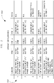
- ESMS 100 of FIGS. 1 and 2 is configurable in multiple configurations as illustrated in FIG. 3 as a table 200.
- Each configuration of ESMS 100 may be selectable by contactors (not illustrated), as understood in the art, and energy flow is controlled by ESMS control algorithms, implemented in controller 46 of hybrid vehicle 10, which can sense a presences of both energy storage devices and charging devices connected to ports 102 and adjust a flow of direction of energy, accordingly.
- the control algorithms may determine a voltage of each port to which an energy storage device or an electrical charging system (DC or rectified AC, as examples) is coupled, and operate ESMS 100 accordingly and based on the determined voltages, based on a measured frequency, or both (as examples).
- a benefit for including a rectifier is that even if DC is connected having the wrong polarity, the rectifier provides protection, even if a single phase rectifier is used or if a DC input is used to two of the 3-phase inputs for a 3-phase rectifier.
- EMS or ESMS includes a low voltage battery 204 that is illustrated as connected to port 1 and an ultracapacitor bank 206 that is connected to port 2.
- a single low voltage battery which represents the main energy storage unit for the EV, is connected to port 1.
- the high voltage port 2 is connected to a ultracapacitor bank or just to the DC link capacitors supplying the motor inverter.
- a charging unit 208 is connected to port 3, which may include either a DC source or a rectified AC source, according to embodiments of the invention. For this case if a charging input voltage at port 3 is higher than the energy battery 204 on port 1, module 2 operates in buck mode.
- an energy/power battery may instead be connected to port 2.
- the remaining ports of the ESMS are left floating.
- two cases are considered depending on the instantaneous voltage level (SOC).
- SOC instantaneous voltage level
- V 2 voltage on port 2
- V 3 voltage on port 3
- charger input module 2 is permanently conducting and module 1 operates in boost mode.
- V 2 ⁇ V 3 the battery is low in SOC (V 2 ⁇ V 3 ) module 2 operates in buck and module 1 in boost mode.
- an energy battery 250 on port 1 represents the main energy storage unit for the EV, and a high voltage or power battery 252 is connected to port 2.
- the integrated wide input voltage range charger allows independent or simultaneously charging of both batteries 250, 252.
- the energy battery 250 on port 1 has typically lower nominal voltages than the power (boost) battery 252.
- charging is also possible even if the port 1 or port 2 voltage is very low. This would be the case if either one of the two batteries (energy side 250 or power side 252) is completely discharged.
- Module 2 254 operates in buck mode and module 1 256 in boost mode. If the charging input 258 (DC or rectified AC) voltage is lower than the port 1 voltage, module 2 210 is turned on all time, module 1 256 boosts to port 2 voltage levels and module 3 260 charges the energy battery 250 on port 1.
- FIG. 5 illustrates a charging configuration from a rectified AC source, it may be misleading that merely relatively low voltages can be used for charging.
- the used port for charging, port 3
- Port 4 has little restrictions in terms of voltage levels.
- Port 4 allows voltage up to a maximum of the overall charger system 262, which may also be device-dependent.
- the illustrated configuration of FIG. 5 is capable of relatively high voltage charging (e.g., IEC mode 4: 400 VDC).
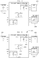
- Embodiments of the invention allow simultaneous charging of energy storage devices from more than one charging source.
- a second charging system may be interfaced with an ESMS, as illustrated in FIG. 6A .
- FIG. 6A illustrates a cutaway lower portion of an ESMS.
- EV applications include two energy storage units, where port 4 is free of use, and a DC source or rectified AC source 264 .
- a rectified AC source 266 may be coupled to port 4, as illustrated, which allows faster charging from a second outlet.
- ports 3 and 4 may be configured having respective electrical sources coupled thereto in order to charge storage devices that are coupled to, for instance, ports 1 and 2 of FIGS. 4 and 5 , as examples.
- FIG. 6B illustrates an alternate embodiment having rectified AC source 266 coupled thereto and a DC source 268 coupled to port 3.
- One advantage of simultaneous charging with multiple sources such as an AC and a DC source is that high power rapid charging can be performed without a need to potentially increase the charge connector beyond what is already a standard (or expected may become a standard). For example, if the AC source and associated mating connectors is designed for level 2, for example 22 kW, and the DC source and associated mating connectors are designed for level 3 or possibly level 4 DC rapid charging at, for instance, approximately 50 kW, then simultaneous charging from both AC and DC sources using embodiments of the invention can be performed at 72 kW by using standard charger connector units (assuming the charge station is able to support these power levels). Without this feature the maximum charge may be approximately 22 kW through the level 2 AC charge connector or 50 kW through the level 3 or level 4 DC charge connector.
- control within the ESMS could be implemented to allow the DC input to be connected to two of the three input terminals and controlled to operate at level 2 at up to 22 kW charge level, depending on the specific current capability for the connector.
- control within the ESMS could be implemented to allow the DC input to be connected to two of the three input terminals and controlled to operate at level 2 at up to 22 kW charge level, depending on the specific current capability for the connector.
- the vehicle is equipped with only AC charge connectors, for example a 3-phase level 2 AC input at 22 kW and single phase level 2 AC at approximately 7.4 kW, simultaneous charging using both AC connectors could be provided at approximately 29.4 kW levels.
- EMS or ESMS 300 includes a first low voltage battery 302 is coupled to port 1, a second low voltage battery 304 coupled to port 4, a high voltage or boost battery 306 coupled to port 2, and a DC source or rectified AC source 308 coupled to port 3.
- source 308 is a rectified DC source which can protect for inadvertently connecting across port 3 having an incorrect polarity.
- the second low voltage battery 304 may be a backup energy battery which allows a higher level of redundancy for safety-critical applications.
- two boost batteries 310, 312 may be connected to respective ports 2 and 3, which may be charged using a DC source or rectified AC source 314 coupled to port 4.
- ESMS 316 acts as a balancing stage while power delivery capability is similar to a parallel configuration.
- Dual battery with integrated wide input range charger and interleaving Dual battery with integrated wide input range charger and interleaving.
- EMS or ESMS 350 is coupled to energy devices in much the same fashion as that illustrated above with respect to FIG. 5 .
- a low voltage battery 352 is coupled to port 1
- a high voltage battery 354 is coupled to port 2
- a rectified AC source or DC source 356 is coupled to port 3.
- module 3 358 is used to interleave during operation of ESMS 350 in order to minimize output current ripple.
- module 1 360 and module 3 358 are connected as shown in FIG. 9 .
- FIG. 10 shows a typical pulse-width modulation (PWM) switching 364 and current waveform 366.
- PWM pulse-width modulation
- the PWM to module 2 362 is generally similar in frequency, just shifted in time by Ts/2 relative to the PWM signal of module 1 360.
- three modules operate in interleaving, the PWM signals to the module 2 362 and module 3 358 are shifted, respectively, by Ts/3 and 2Ts/3.
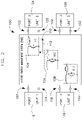
- FIG. 11 illustrates a block diagram of a multi-port ESMS according to an embodiment of the invention.
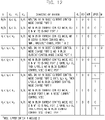
- contactors illustrated in FIG. 11 may be controlled according to the table illustrated in FIG. 12 .
- ESMS 400 illustrates a first buck-boost module 402, a second buck-boost module 404, and a third buck-boost module 406.
- ESMS 400 also illustrates port 1 408 having a low voltage battery coupled thereto, port 2 410 having a high voltage unit coupled thereto, port 3 412 having a rectified AC or DC voltage coupled thereto, and port 4 414 having a low voltage ultracapacitor coupled thereto.
- energy storage devices and an energy charger are coupled to ESMS 400 in order to illustrate operation according to one configuration.
- ESMS 400 may be configured in numerous arrangements in order to accommodate multiple charger/energy storage arrangements.
- ESMS 400 includes contactors KU 416, KV 418, KW 420, UPOS 422, and M 424 which may be selectively engaged or disengaged in order to accomplish configurations for charging, according to the illustrations above.
- Each of the three buck-boost modules 402, 404, 406 includes an IGBT leg (upper and lower switch) and an inductor.
- the high voltage DC bus is buffered by a number of power capacitors.
- Each buck-boost converter stage output is equipped with a current sensor, which measures an inductor current. Voltage limits show at port 3 are originated by typical single-phase AC outlet voltages in both the US and Europe.
- ESMS 400 uses contactors as main bus and individual module switches.
- the pre-charge circuit is realized using two power resistors (e.g., 120 ohm, 100 W, RH-50) and a contactor or FET.
- An additional contactor (UPOS 422 in FIG. 11 ) serves in two cases. One is under a certain SOC condition of a battery at port 1, and the second if interleaving of module 1 and module 3 is enabled.
- FIG. 11 illustrates voltage and current sense points of ESMS 400 having an integrated charger.
- control of specific charging operations may be by selective engagement and disengagement of contactors 416 - 424.
- multi-port energy management is fully functional. Even if for some reason it is desired to equip the system with a separate charger, the multi-port ESMS still performs its function, which is at a minimum energy management between ports 1, 2 and 4. After completed pre-charge of the DC link capacitors, the ESMS sets the individual phase state machines into manual mode and sets the current commands and starts regulating after a sanity check of the contactor states.
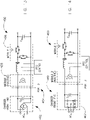
- port 3 of the illustrated ESMS 450 may be charged from a 1-phase AC source 452, thus a simple high-power factor boost pre-regulator can be realized according to an embodiment of the invention.
- ESMS 450 is connected to a single-phase rectifier on port 3 454, for instance, as shown in FIG. 13 , module 1 456 and module 2 458 are used by operating in a high-power factor regulator mode.
- FIG. 13 illustrates a simple approach of a rectified AC source having a power factor correction (PFC) pre-regulator, C in is a small high frequency bypass capacitor, and C out is a bulk storage capacitor or DC bus capacitor.
- PFC power factor correction
- the control in AC mode is performing.
- First is to limit the maximum charging current drawn from the utility grid to the specified maximum that is limited by the line or circuit breaker.
- the PFC boost stage shapes the current to minimize the phase angle between input current and input voltage.
- the circuit illustrated is essentially a boost converter with wide input range that is capable of precisely controling an input current (current shaping).
- the current in waveshape and phase to the input voltage is controlled instantaneously.
- a relatively large capacitor at the output of the boost stage supplies short peak energy demands, while the input capacitor is reduced to a few microfarads.
- EMI filter components are standards components and will be connected between the corresponding front-end and the mechanical interface to the HVSE, as understood in the art.
- ESMS 450 can include a rectifier front-end 460 for a 3-phase charger input 462 designed in a similar fashion as that illustrated in FIG. 13 .
- an integrated charger configuration of ESMS port 3 of FIGS. 13 and 14 can be used as a charger input.
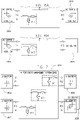
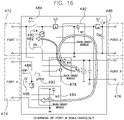
- FIGS. 15 and 16 energy flow for two configurations of charging is illustrated.
- energy is to flow from a charger (not illustrated) positioned on port 3 464, to module 2 466, and to module 1 468 operating in boost mode.
- a DC source may be boosted to a high-voltage output on port 2 470, by ensuring KV and KW are open.
- port 1 472 and port 4 474 may be charged simultaneously from a DC source (not shown) coupled to port 3 476. Two cases may be considered regarding FIG. 16 , as examples.
- Case 1 Input voltage at port 3 476 is higher than battery voltage at port 1 472.
- module 2 478 operates in buck mode and the current IL4 480 in LU is regulated.
- Contactors KU 482 and KV 484 are closed, while M 486, KW 488 and UPOS 490 are open.
- Input voltage at port 3 476 is lower than battery voltage at port 1 472.
- contactors KU 482, M 486 and UPOS 490 are closed, while KV 484 and KW 488are open.
- Module 2 478 is inactive (M2U is permanently on), module 1 492 operates in boost mode to boost the low input voltage up to some higher level.
- Module 3 494 bucks this voltage back to the set voltage of the energy battery at port 1 472.
- the current IL2 496 in LW is controlled in a closed loop fashion.
- energy and e-motor drivetrains typically include components from different vendors. As a result many units are duplicated, with many single point failure possibilities in the system. Thus, the integration of functions into one instead of three or four management units will result in a reliability improvement, according to embodiments of the invention. From the perspective of a battery manufacturer for example, where good knowledge of the battery cell behavior is available, an integration of ESMS and charger function is desirable. Further, although an EV is specifically mentioned, as mentioned, embodiments of the invention may be used for a PHEV or series hybrid as well. In this case one of the ports on the left could be used to transfer energy from an Auxiliary Power Unit (APU), that can operate in charge sustaining mode.
- APU Auxiliary Power Unit
- ESMS 500 includes an electrical output from an internal combustion engine (ICE) 502 coupled to port 1, and either a LV battery 506 or a rectified AC source 506 coupled to port 4.
- the electrical output from ICE 502 may be an alternator that outputs DC electrical power, in one embodiment.
- a power battery 508 is coupled to port 2 and an AC source or DC source 510 may be coupled to port 3.
- ICE 502 provides flexibility for extended vehicle range while providing an ability to charge energy storage system from separate ports.
- a technical contribution for the disclosed apparatus is that it provides for a controller implemented technique for charging energy storage devices of an electric vehicle.
- an energy storage management system includes one or more energy storage devices coupled to a vehicle drivetrain and configured to store DC energy, a power electronic conversion system having a plurality of energy ports, the power electronic conversion system comprising a plurality of DC electrical converters, each DC electrical converter configured to step up and to step down a DC voltage, wherein each of the plurality of energy ports is coupleable to each of the one or more energy storage devices and each of the plurality of energy ports is coupleable to an electrical charging system.
- the EV includes a controller configured to determine a voltage of each energy port having either an energy storage device or a DC electrical charging system coupled thereto, and electrically connect a first energy port to a second energy port of at least two of the energy ports such that at least one of the DC electrical converters either steps up or steps down an input DC voltage based on the determined voltage of each energy port.
- a method of fabricating an energy storage and management system includes coupling one or more energy storage devices to a vehicle powertrain, fabricating a charging device having a plurality of buck-boost converters, attaching the charging device to the vehicle, the charging device comprising a plurality of energy ports, each of the plurality of energy ports coupleable to each of the one or more energy storage devices, sensing a voltage across each of the plurality of energy ports, determining if an energy storage device and an electrical charging system is coupled to any of the plurality of energy ports based on the sensed voltage, and electrically connecting the electrical charging system to any of the plurality of energy ports having an energy storage device by selectively directing electrical current to flow through one or more of the plurality of buck-boost converters.
- ESMS energy storage and management system
- a non-transitory computer readable storage medium positioned on an energy storage and management system (ESMS) and having stored thereon a computer program comprising instructions which when executed by a computer cause the computer to determine a voltage of each energy port of a multi-port power conversion system that is positioned on the ESMS, and electrically connect at least two of the energy ports such that electrical energy passes from a first of the at least two energy ports to a second of the at least two energy ports and through at least two buck-boost converters, a first buck-boost converter of the at least two buck-boost converters configured to operate in a boost mode, and a second buck-boost converter of the at least two buck-boost converters configured to operate in a buck mode.
- ESMS energy storage and management system
Landscapes
- Engineering & Computer Science (AREA)
- Power Engineering (AREA)
- Transportation (AREA)
- Mechanical Engineering (AREA)
- Sustainable Energy (AREA)
- Sustainable Development (AREA)
- Life Sciences & Earth Sciences (AREA)
- Charge And Discharge Circuits For Batteries Or The Like (AREA)
- Electric Propulsion And Braking For Vehicles (AREA)
- Hybrid Electric Vehicles (AREA)
- Secondary Cells (AREA)
- Arrangement Or Mounting Of Propulsion Units For Vehicles (AREA)
- Control Of Charge By Means Of Generators (AREA)
Abstract
Description
- Embodiments of the invention relate generally to electric drive systems including hybrid and electric vehicles and, more particularly, to charging an electric vehicle using a multiport energy management system.
- Hybrid electric vehicles may combine an internal combustion engine and an electric motor powered by an energy storage device, such as a traction battery, to propel the vehicle. Such a combination may increase overall fuel efficiency by enabling the combustion engine and the electric motor to each operate in respective ranges of increased efficiency. Electric motors, for example, may be efficient at accelerating from a standing start, while internal combustion engines (ICEs) may be efficient during sustained periods of constant engine operation, such as in highway driving. Having an electric motor to boost initial acceleration allows combustion engines in hybrid vehicles to be smaller and more fuel efficient.
- Purely electric vehicles use stored electrical energy to power an electric motor, which propels the vehicle and may also operate auxiliary drives. Purely electric vehicles may use one or more sources of stored electrical energy. For example, a first source of stored electrical energy may be used to provide longer-lasting energy (such as a low-voltage battery) while a second source of stored electrical energy may be used to provide higher-power energy for, for example, acceleration (such as a high-voltage battery or an ultracapacitor).
- Plug-in electric vehicles, whether of the hybrid electric type or of the purely electric type, are configured to use electrical energy from an external source to recharge the energy storage devices. Such vehicles may include on-road and off-road vehicles, golf carts, neighborhood electric vehicles, forklifts, and utility trucks as examples. These vehicles may use either off-board stationary battery chargers, on-board battery chargers, or a combination of off-board stationary battery chargers and on-board battery chargers to transfer electrical energy from a utility grid or renewable energy source to the vehicle's on-board traction battery. Plug-in vehicles may include circuitry and connections to facilitate the recharging of the traction battery from the utility grid or other external source, for example.
- Battery chargers are important components in the development of electric vehicles (EVs). Historically, two types of chargers for EV application are known. One is a standalone type where functionality and style can be compared to a gas station to perform rapid charging. The other is an on-board type, which would be used for slower C-rate charging from a conventional household outlet. EVs typically include energy storage devices such as low voltage batteries (for range and cruising, for example), high voltage batteries (for boost and acceleration, for example), and ultracapacitors (for boost and acceleration, for example), to name a few. Because these energy storage devices operate under different voltages and are charged differently from one another, typically each storage device includes its own unique charging system. This can lead to multiple components and charging systems because the storage devices typically cannot be charged using charging systems for other storage devices. In other words, a charging device used to charge a low-voltage battery typically cannot be used to charge an ultracapacitor or a high-voltage battery.
- The effect (i.e., many devices) is generally compounded when considering that in some applications it is desirable to rapidly charge the storage device using a "gas station" type charging system, while in other applications it is desirable to slow-charge the storage device using a conventional household outlet. Thus, in order to provide charging capability for multiple energy storage device types and using either a rapid charge or a slow charge system, several charger types may be necessary in order to provide all of the desired functionality. Because each charger type accordingly includes a system of electrical components, reliability of the overall system may be compromised because of the large number of components that may be used in order to provide this functionality. And, although the electric and electronic components can be sized such that electrical stress levels are low, the relatively high on-duty cycle can influence the reliability significantly, as well.
- It would therefore be desirable to provide an apparatus to reduce the overall number of electrical components while providing flexibility to charge an EV
- According to one aspect of the invention, an energy storage management system (ESMS) includes one or more energy storage devices coupled to a drivetrain and configured to store DC energy, a power electronic conversion system having a plurality of energy ports, the power electronic conversion system comprising a plurality of DC electrical converters, each DC electrical converter configured to step up and to step down a DC voltage, wherein each of the plurality of energy ports is coupleable to each of the one or more energy storage devices and each of the plurality of energy ports is coupleable to an electrical charging system. The EV includes a controller configured to determine a voltage of each energy port having either an energy storage device or a DC electrical charging system coupled thereto, and electrically connect a first energy port to a second energy port of at least two of the energy ports such that at least one of the DC electrical converters either steps up or steps down an input DC voltage based on the determined voltage of each energy port.
- In accordance with another aspect of the invention, a method of fabricating an energy storage and management system (ESMS) includes coupling one or more energy storage devices to a vehicle powertrain, fabricating a charging device having a plurality of buck-boost converters, attaching the charging device to the vehicle, the charging device comprising a plurality of energy ports, each of the plurality of energy ports coupleable to each of the one or more energy storage devices, sensing a voltage across each of the plurality of energy ports, determining if an energy storage device and an electrical charging system is coupled to any of the plurality of energy ports based on the sensed voltage, and electrically connecting the electrical charging system to any of the plurality of energy ports having an energy storage device by selectively directing electrical current to flow through one or more of the plurality of buck-boost converters.
- In accordance with yet another aspect of the invention, a non-transitory computer readable storage medium positioned on an energy storage and management system (ESMS) and having stored thereon a computer program comprising instructions which when executed by a computer cause the computer to determine a voltage of each energy port of a multi-port power conversion system that is positioned on the ESMS, and electrically connect at least two of the energy ports such that electrical energy passes from a first of the at least two energy ports to a second of the at least two energy ports and through at least two buck-boost converters, a first buck-boost converter of the at least two buck-boost converters configured to operate in a boost mode, and a second buck-boost converter of the at least two buck-boost converters configured to operate in a buck mode.
- Various other features and advantages will be made apparent from the following detailed description and the drawings.
- The drawings illustrate embodiments presently contemplated for carrying out the invention.
- In the drawings:
-
FIG. 1 is a schematic block diagram of an electric vehicle (EV) incorporating embodiments of the invention. -
FIG. 2 is a schematic diagram of a configurable multi-port charger architecture according to an embodiment of the invention. -
FIG. 3 is a table illustrating configurations as of the multi-port charger illustrated inFIG. 2 . -
FIG. 4 is an illustration of the multi-port charger ofFIG. 2 according to one configuration. -
FIG. 5 is an illustration of the multi-port charger ofFIG. 2 according to one configuration. -
FIGS. 6A and 6B are illustrations of the multi-port charger ofFIG. 5 according to alternate configurations. -
FIG. 7 is an illustration of the multi-port charger ofFIG. 2 according to one configuration. -
FIG. 8 is an illustration of the multi-port charger ofFIG. 2 according to one configuration. -
FIG. 9 is an illustration of the multi-port charger ofFIG. 2 according to one configuration. -
FIG. 10 illustrates a typical pulse-width modulation (PWM) switching and waveform. -
FIG. 11 illustrates a block diagram of a multi-port charger according to an embodiment of the invention. -
FIG. 12 illustrates charging arrangements that may be selectively engaged and disengaged of the multi-port charger ofFIG. 2 . -
FIG. 13 illustrates a multi-port charger having a 1-phase AC source. -
FIG. 14 illustrates a multi-port charger having a 3-phase AC source. -
FIG. 15 illustrates energy flow in a multi-port charger according to a configuration of operation. -
FIG. 16 illustrates energy flow in a multi-port charger according to a configuration of operation. -
FIG. 17 illustrates a multi-port charger having an energy input from an internal combustion engine (ICE) according to an embodiment of the invention. -
FIG. 1 illustrates one embodiment of a hybrid electric vehicle (HEV) or electric vehicle (EV) 10, such as an automobile, truck, bus, or off-road vehicle, for example, incorporating embodiments of the invention.Vehicle 10 includes an energy storage and management system (ESMS) 11 internal combustion orheat engine 12, atransmission 14 coupled toengine 12, a differential 16, and adrive shaft assembly 18 coupled betweentransmission 14 anddifferential 16. And, although ESMS 11 is illustrated in a plug-in hybrid electric vehicle (PHEV), it is understood that ESMS 11 is applicable to any electric vehicle, such as a HEV or EV or other power electronic drives used to operate pulsed loads, according to embodiments of the invention. According to various embodiments,engine 12 may be an internal combustion gasoline engine, an internal combustion diesel engine, an external combustion engine, or a gas turbine engine, as examples. ESMS 11 includes anengine controller 20 provided to control operation ofengine 12. According to one embodiment,engine controller 20 includes one ormore sensors 22 that are configured to sense operating conditions ofengine 12.Sensors 22 may include an rpm sensor, a torque sensor, an oxygen sensor, and a temperature sensor as examples. As such,engine controller 20 is configured to transmit or receive data fromengine 12.Vehicle 10 also includes an engine speed sensor (not shown) that measures a crankshaft speed ofengine 12. According to one embodiment, speed sensor may measure engine crankshaft speed from a tachometer (not shown) in pulses per second, which may be converted to a revolutions per minute (rpm) signal. -
Vehicle 10 also includes at least twowheels 24 that are coupled to respective ends ofdifferential 16. In one embodiment,vehicle 10 is configured as a rear wheel drive vehicle such that differential 16 is positioned near an aft end ofvehicle 10 and is configured to drive at least one of thewheels 24. Optionally,vehicle 10 may be configured as a front-wheel drive vehicle. - In one embodiment,
transmission 14 is a manually operated transmission that includes a plurality of gears such that the input torque received fromengine 12 is multiplied via a plurality of gear ratios and transmitted to differential 16 throughdrive shaft assembly 18. According to such an embodiment,vehicle 10 includes a clutch (not shown) configured to selectively connect and disconnectengine 12 andtransmission 14. -
Vehicle 10 also includes an electromechanical device such as an electric motor or electric motor/generator unit 26 coupled alongdrive shaft assembly 18 betweentransmission 14 and differential 16 such that torque generated byengine 12 is transmitted throughtransmission 14 and through electric motor or electric motor/generator unit 26 to differential 16. A speed sensor (not shown) may be included to monitor an operating speed ofelectric motor 26. According to one embodiment,electric motor 26 is directly coupled totransmission 14, and driveshaft assembly 18 comprises one axle or drive shaft coupled to differential 16. - A hybrid drive control system or
torque controller 28 is provided to control operation ofelectric motor 26 and is coupled to motor/generator unit 26. Anenergy storage system 30 is coupled totorque controller 28 and comprises a low voltage energy storage orenergy battery 32, a high voltage energy storage orpower battery 34, and anultracapacitor 36, as examples. However, although a lowvoltage energy storage 32, a highvoltage energy storage 34, and anultracapacitor 36 are illustrated, it is to be understood thatenergy storage system 30 may include a plurality of energy storage units as understood in the art such as sodium metal halide batteries, sodium nickel chloride batteries, sodium sulfur batteries, nickel metal hydride batteries, lithium ion batteries, lithium polymer batteries, nickel cadmium batteries, a plurality of ultracapacitor cells, a combination of ultracapacitors and batteries, or a fuel cell, as examples. Anaccelerator pedal 38 andbrake pedal 40 are also included invehicle 10.Accelerator pedal 38 is configured to send throttle command signals or accelerator pedal signals toengine controller 20 andtorque control 28. -
System 10 includes acharger 42 coupled to energy storage units 32 - 36 ofenergy storage system 30, according to embodiments of the invention.Charger 42 may be coupled to multiple energy storage systems 32 - 36, as illustrated andcharger 42 may be coupled to one or multiple power input lines 44, two of which are illustrated, according to embodiments of the invention. That is,charger 42 illustrates an embodiment of the invention, andcharger 42 may be coupled to one or multiple energy storage systems, andcharger 42 may be coupled to one or multiplepower input systems 44, according to embodiments illustrating use of the invention.Charger 42 includes acontroller 46 that is configured to selectively engage and disengage DC electrical devices or buck-boost modules ofcharger 42 as will be discussed. - And, although
charger 42 is illustrated as being coupled to energy storage systems 32 - 36, andcharger 42 is illustrated as coupled to one or multiple power input lines 44, it is to be understood that embodiments of the invention are not to be so limited. Instead, it is to be understood thatcharger 42 may be coupled to multiple and varying types of energy storage systems and power inputs, some of which are illustrated in the following figures. Further, it is to be understood that there may bemultiple chargers 42 per vehicle in parallel, or that there may be power systems applied to eachwheel 24 ofvehicle 10, each having acharger 42 coupled thereto. - In operation, it is understood in the art that energy may be provided to drive
shaft assembly 18 from internal combustion orheat engine 12 viatransmission 14, and energy may be provided to driveshaft assembly 18 viadrive control system 28 having energy drawn fromenergy storage system 30 that may include energy systems 32 - 36. Thus, as understood in the art, energy may be drawn forvehicle 10 boost or acceleration from, for instance a highvoltage storage device 34 that may include a battery, as an example, or fromultracapacitor 36. During cruising (i.e., generally non-accelerating operation), energy may be drawn forvehicle 10 via a low voltage storage device such as lowvoltage energy storage 32. - And, during operation, energy may be drawn from internal combustion or
heat engine 12 in order toenergy storage 30 or provide power to driveshaft assembly 18 as understood in the art. Further, some systems include a regenerative operation where energy may be recovered from a braking operation and used to re-chargeenergy storage 30. In addition, some systems may not provide regenerative energy recovery from braking and some systems may not provide a heat engine such as internal combustion orheat engine 12. Nevertheless and despite the ability of some systems to re-chargeenergy storage 30,energy storage 30 periodically requires re-charging from an external source such as a 115 V household supply or a 230 V 3-phase source, as examples. The requirement to re-chargeenergy storage 30 is particularly acute in a plug-in hybrid electric vehicle (PHEV) having no heat engine to provide power and an extended range of driving operation. - Thus, embodiments of the invention are flexible and configurable having a plurality of energy ports, and may be coupled to multiple power sources and source types in order to charge one or multiple energy storage types. Further, as will be illustrated, embodiments of the invention allow charging of an energy storage unit that is fully depleted and having a starting voltage that is below a voltage of a power source, and embodiments of the invention allow charging of an energy storage unit to voltages that are in excess of a voltage of the power source.
- To meet the demands of modern PHEVs and EVs, the infrastructure should provide typically 7 kW to achieve a state-of-charge (SOC) gain of 80% (assuming a 25 kWh battery) in a charging time of 2 or 3 hours (home charging). For a more aggressive short stop fast charging scenario (e.g., a "gas station") significant higher power levels may be required to achieve a desired 80% SOC in 10 minutes. The vehicle interface needs to be designed according to existing standards. A pilot signal determines by its duty cycle the maximum allowable power. Besides a high degree of integration the proposed system provides also single and or three phase AC input, high efficiency, low harmonics, nearly unity input power factor, low cost, low weight and safety interlocking of the equipment. The power factor correction (PFC) requirement may be driven by IEC/ISO/IEEE line harmonic current regulations, as known in the art.
- Illustrated in the following figures is an energy management system with an integrated charger unit consisting of three bi-directional buck-boost stages and a charger front end. The system includes also a charger module for high voltage DC and standard AC outlet charging.
- This invention is applicable to conventional electric vehicles (EVs) as well as grid-charged hybrid electric vehicles (PHEVs). Grid-charged HEVs provide the option to drive the vehicle for a certain number of miles (i.e., PHEV20, PHEV40, PHEV60). Traditionally, the goal for PHEVs is to provide a high all-electric-range (AER) capability to lower operating cost and be able to optimize the operating strategy. In terms of the buck-boost stages, the charger front-end and interface, it generally makes no difference if it is designed for an EV or PHEV application. The role of the DC/DC converter is an efficient energy transfer between two or more energy sources, reliable for continuous and peak power demands. The integration of the charger unit is the next step towards a higher power density design with fewer components and therefore higher reliability. As such, embodiments of the invention are applicable to multiple electric vehicles, including all-electric and hybrid electric vehicles, as examples, designated generally and broadly as "EV"s. Such EVs may include but are not limited to road vehicles, golf carts, trains, and the like, capable of having power systems that include an electric component for causing motion of the vehicle.
- In conventional implementations many separate units coexist, to include generally a separate charger, battery management and control unit that are interconnected. In an automotive environment with advanced batteries, communications between the charger and battery or other vehicle systems from different vendors seamless integration is an important consideration. The energy management system with integrated charger is advantageous in that aspect that there is less integration effort required and fewer components improve reliability.
- Referring now to
FIG. 2 , a configurable multi-port integrated charger architecture, energy storage and management system (ESMS, otherwise referred to as energy management system (EMS))ESMS 100, such ascharger 42 is illustrated having fourenergy ports 102 and three DC electrical conversion devices or buck-boost converters respectively asmodules boost converter 104, but equally applicable toconverts 106 and 108), or a boost mode by flowing electrical energy in a second direction 112 (illustrated again with respect to buck-boost converter 104, but equally applicable toconverts 106 and 108). As illustrated,energy ports 102 comprise afirst energy port 114 configurable to have afirst unit 116 attached or electrically coupled thereto. Similarly,energy ports 102energy port 118 120 122 are configurable to have respectivesecond unit 124,third unit 126, andfourth unit 128 attached or electrically coupled thereto. - According to the invention the charger is entirely part of the vehicle design and mounted on-board. The integrated on-board charger is capable of continuously adjusting an input current as a result of, for instance, a state-of-charge (SOC) of a device connected thereto for charging. The integrated charger energy management system is equipped with a minimum number of standard components and is thus able to efficiently charge a plurality of energy storage systems and system types while having a minimum cost. In one embodiment, each of the shown basic modules is furthermore equipped with only one additional contactor to perform the different functions described below and to allow isolation of the ports. The configuration of the three individual modules M1 to M3 in
FIG. 2 in conjunction with the appropriate charging algorithm allows energy transfer from arectified AC or directly from a DC source to different energy storage units connected to the ports of the ESMS. - As will be illustrated,
ESMS 100 ofFIG. 2 may be configured to charge up to three energy sources (to include low voltage energy batteries, high voltage power batteries, ultracapacitors, as examples) at the same time or simultaneously.ESMS 100 may have modules therein configured to be interleaved in order to lower ripple current.ESMS 100 also is capable of having multiple charging profiles as a function of SOC and temperature, as examples, for different battery technologies and storage device types.ESMS 100 includes a centralized energy flow control that is centrally controlled by a controller such ascontroller 46 ofFIG. 1 , andESMS 100 is capable of managing a wide range of input and output voltages. -
ESMS 100 ofFIGS. 1 and2 is configurable in multiple configurations as illustrated inFIG. 3 as a table 200. Each configuration ofESMS 100 may be selectable by contactors (not illustrated), as understood in the art, and energy flow is controlled by ESMS control algorithms, implemented incontroller 46 ofhybrid vehicle 10, which can sense a presences of both energy storage devices and charging devices connected toports 102 and adjust a flow of direction of energy, accordingly. For instance, the control algorithms may determine a voltage of each port to which an energy storage device or an electrical charging system (DC or rectified AC, as examples) is coupled, and operateESMS 100 accordingly and based on the determined voltages, based on a measured frequency, or both (as examples). And, a benefit for including a rectifier is that even if DC is connected having the wrong polarity, the rectifier provides protection, even if a single phase rectifier is used or if a DC input is used to two of the 3-phase inputs for a 3-phase rectifier. - According to a
first configuration 202, illustrated inFIG. 4 , EMS or ESMS includes alow voltage battery 204 that is illustrated as connected toport 1 and anultracapacitor bank 206 that is connected toport 2. In this configuration a single low voltage battery, which represents the main energy storage unit for the EV, is connected toport 1. Thehigh voltage port 2 is connected to a ultracapacitor bank or just to the DC link capacitors supplying the motor inverter. A chargingunit 208 is connected toport 3, which may include either a DC source or a rectified AC source, according to embodiments of the invention. For this case if a charging input voltage atport 3 is higher than theenergy battery 204 onport 1,module 2 operates in buck mode. - Two cases may be considered. First, if the nominal voltage of the energy battery on
port 1 is lower than the lowest charger input voltage, then the charging algorithm operates as just described. Second, if the nominal voltage of thebattery 204 is higher than thecharger 208 input voltage,module 2 210 is permanently conducting,module 1 212 operates in boost mode andmodule 3 214 operates in buck mode to charge thebattery 204. - In a second configuration for this section (not illustrated) an energy/power battery may instead be connected to
port 2. The remaining ports of the ESMS are left floating. In this scenario two cases are considered depending on the instantaneous voltage level (SOC). For normal SOC levels, where V2 (voltage on port 2) is higher than V3 (voltage onport 3, charger input)module 2 is permanently conducting andmodule 1 operates in boost mode. For the case where the battery is low in SOC (V2 < V3)module 2 operates in buck andmodule 1 in boost mode. - Referring now to
FIG. 5 , in this configuration anenergy battery 250 onport 1 represents the main energy storage unit for the EV, and a high voltage orpower battery 252 is connected toport 2. The integrated wide input voltage range charger allows independent or simultaneously charging of bothbatteries energy battery 250 onport 1 has typically lower nominal voltages than the power (boost)battery 252. However, in this configuration charging is also possible even if theport 1 orport 2 voltage is very low. This would be the case if either one of the two batteries (energy side 250 or power side 252) is completely discharged.Module 2 254 operates in buck mode andmodule 1 256 in boost mode. If the charging input 258 (DC or rectified AC) voltage is lower than theport 1 voltage,module 2 210 is turned on all time,module 1 256 boosts toport 2 voltage levels andmodule 3 260 charges theenergy battery 250 onport 1. - And, although
FIG. 5 illustrates a charging configuration from a rectified AC source, it may be misleading that merely relatively low voltages can be used for charging. In fact, the used port (for charging, port 3) has little restrictions in terms of voltage levels.Port 4, for example, allows voltage up to a maximum of theoverall charger system 262, which may also be device-dependent. As such, the illustrated configuration ofFIG. 5 is capable of relatively high voltage charging (e.g., IEC mode 4: 400 VDC). - Embodiments of the invention allow simultaneous charging of energy storage devices from more than one charging source. In one example, a second charging system may be interfaced with an ESMS, as illustrated in
FIG. 6A . Thus,FIG. 6A illustrates a cutaway lower portion of an ESMS. In illustrated embodiments above, EV applications include two energy storage units, whereport 4 is free of use, and a DC source or rectifiedAC source 264 . However, according to embodiments of the invention, a rectifiedAC source 266 may be coupled toport 4, as illustrated, which allows faster charging from a second outlet. Thus, according to embodiments of the invention,ports ports FIGS. 4 and 5 , as examples. However,FIG. 6B illustrates an alternate embodiment having rectifiedAC source 266 coupled thereto and aDC source 268 coupled toport 3. - One advantage of simultaneous charging with multiple sources such as an AC and a DC source is that high power rapid charging can be performed without a need to potentially increase the charge connector beyond what is already a standard (or expected may become a standard). For example, if the AC source and associated mating connectors is designed for
level 2, for example 22 kW, and the DC source and associated mating connectors are designed forlevel 3 or possiblylevel 4 DC rapid charging at, for instance, approximately 50 kW, then simultaneous charging from both AC and DC sources using embodiments of the invention can be performed at 72 kW by using standard charger connector units (assuming the charge station is able to support these power levels). Without this feature the maximum charge may be approximately 22 kW through thelevel 2 AC charge connector or 50 kW through thelevel 3 orlevel 4 DC charge connector. Furthermore, if the vehicle is only equipped with alevel 2 3-phase charge connector, control within the ESMS could be implemented to allow the DC input to be connected to two of the three input terminals and controlled to operate atlevel 2 at up to 22 kW charge level, depending on the specific current capability for the connector. For another case where the vehicle is equipped with only AC charge connectors, for example a 3-phase level 2 AC input at 22 kW andsingle phase level 2 AC at approximately 7.4 kW, simultaneous charging using both AC connectors could be provided at approximately 29.4 kW levels. - Referring to
FIG. 7 , a triple energy storage configuration is illustrated that allows charging from a wide voltage range input, according to an embodiment. According to the illustrated configuration, EMS orESMS 300 includes a firstlow voltage battery 302 is coupled toport 1, a secondlow voltage battery 304 coupled toport 4, a high voltage or boostbattery 306 coupled toport 2, and a DC source or rectifiedAC source 308 coupled toport 3. In one example,source 308 is a rectified DC source which can protect for inadvertently connecting acrossport 3 having an incorrect polarity. In one example, the secondlow voltage battery 304 may be a backup energy battery which allows a higher level of redundancy for safety-critical applications. - Referring to
FIG. 8 , twoboost batteries respective ports AC source 314 coupled toport 4. Thus, two high power/high voltage energy storage units can be connected in parallel in order to achieve maximum boost performance while a certain degree of energy management is still maintained. However, instead of simply paralleling the two units,ESMS 316 acts as a balancing stage while power delivery capability is similar to a parallel configuration. - Referring to
FIG. 9 , EMS orESMS 350 is coupled to energy devices in much the same fashion as that illustrated above with respect toFIG. 5 . As such, alow voltage battery 352 is coupled toport 1, ahigh voltage battery 354 is coupled toport 2, and a rectified AC source orDC source 356 is coupled toport 3. However, in this mode,module 3 358 is used to interleave during operation ofESMS 350 in order to minimize output current ripple. - That is, in interleaved mode, power is transferred through two or three modules (
module 1 360,module 2 362, andmodule 3 358) and produces a smaller output current ripple, compared to that ofFIG. 5 , while at the same time reduces the size of magnetic and other components. For interleaved mode with two modules,module 1 360 andmodule 3 358 are connected as shown inFIG. 9 . Further,FIG. 10 shows a typical pulse-width modulation (PWM) switching 364 andcurrent waveform 366. In interleaving mode the PWM tomodule 2 362 is generally similar in frequency, just shifted in time by Ts/2 relative to the PWM signal ofmodule 1 360. And, three modules operate in interleaving, the PWM signals to themodule 2 362 andmodule 3 358 are shifted, respectively, by Ts/3 and 2Ts/3. -
FIG. 11 illustrates a block diagram of a multi-port ESMS according to an embodiment of the invention. Thus, in the aforementioned embodiments, contactors illustrated inFIG. 11 may be controlled according to the table illustrated inFIG. 12 . - Referring first to
FIG. 11 , for simplicity, control electronic components are omitted. Thus, ESMS 400 illustrates a first buck-boost module 402, a second buck-boost module 404, and a third buck-boost module 406. ESMS 400 also illustratesport 1 408 having a low voltage battery coupled thereto,port 2 410 having a high voltage unit coupled thereto,port 3 412 having a rectified AC or DC voltage coupled thereto, andport 4 414 having a low voltage ultracapacitor coupled thereto. Thus, in the example illustrated, energy storage devices and an energy charger are coupled to ESMS 400 in order to illustrate operation according to one configuration. However, as discussed, ESMS 400 may be configured in numerous arrangements in order to accommodate multiple charger/energy storage arrangements. As such, ESMS 400 includes contactors KU 416,KV 418,KW 420,UPOS 422, andM 424 which may be selectively engaged or disengaged in order to accomplish configurations for charging, according to the illustrations above. - Each of the three buck-
boost modules - Each buck-boost converter stage output is equipped with a current sensor, which measures an inductor current. Voltage limits show at
port 3 are originated by typical single-phase AC outlet voltages in both the US and Europe. - ESMS 400 uses contactors as main bus and individual module switches. The pre-charge circuit is realized using two power resistors (e.g., 120 ohm, 100 W, RH-50) and a contactor or FET. An additional contactor (
UPOS 422 inFIG. 11 ) serves in two cases. One is under a certain SOC condition of a battery atport 1, and the second if interleaving ofmodule 1 andmodule 3 is enabled.FIG. 11 illustrates voltage and current sense points of ESMS 400 having an integrated charger. - Thus, referring now to
FIG. 12 , one skilled in the art will recognize that control of specific charging operations may be by selective engagement and disengagement of contactors 416 - 424. - It will be recognized that in configurations illustrated herein, multi-port energy management is fully functional. Even if for some reason it is desired to equip the system with a separate charger, the multi-port ESMS still performs its function, which is at a minimum energy management between
ports - Referring now to
FIG. 13 ,port 3 of the illustratedESMS 450 may be charged from a 1-phase AC source 452, thus a simple high-power factor boost pre-regulator can be realized according to an embodiment of the invention. IfESMS 450 is connected to a single-phase rectifier onport 3 454, for instance, as shown inFIG. 13 ,module 1 456 andmodule 2 458 are used by operating in a high-power factor regulator mode. Thus,FIG. 13 illustrates a simple approach of a rectified AC source having a power factor correction (PFC) pre-regulator, Cin is a small high frequency bypass capacitor, and Cout is a bulk storage capacitor or DC bus capacitor. - Thus, there are two basic functions the control in AC mode is performing. First is to limit the maximum charging current drawn from the utility grid to the specified maximum that is limited by the line or circuit breaker. Second, the PFC boost stage shapes the current to minimize the phase angle between input current and input voltage. The circuit illustrated is essentially a boost converter with wide input range that is capable of precisely controling an input current (current shaping). The current in waveshape and phase to the input voltage is controlled instantaneously. A relatively large capacitor at the output of the boost stage supplies short peak energy demands, while the input capacitor is reduced to a few microfarads.
- Any desired EMI filter are not shown in the previous figures. EMI filter components are standards components and will be connected between the corresponding front-end and the mechanical interface to the HVSE, as understood in the art.
- Referring now to
FIG. 14 ,ESMS 450 can include a rectifier front-end 460 for a 3-phase charger input 462 designed in a similar fashion as that illustrated inFIG. 13 . - In an additional embodiment, an integrated charger configuration of
ESMS port 3 ofFIGS. 13 and 14 can be used as a charger input. A type control of charging depends on a voltage level as indicated inFIG. 12 , having corresponding contactor states KU = closed, KV = open, KW = open, UPOS = open, and M = closed. - Referring to
FIGS. 15 and16 , energy flow for two configurations of charging is illustrated. Referring first toFIG. 15 , energy is to flow from a charger (not illustrated) positioned onport 3 464, tomodule 2 466, and tomodule 1 468 operating in boost mode. As such, a DC source may be boosted to a high-voltage output onport 2 470, by ensuring KV and KW are open. - In another example illustrated in
FIG. 16 ,port 1 472 andport 4 474 may be charged simultaneously from a DC source (not shown) coupled toport 3 476. Two cases may be considered regardingFIG. 16 , as examples. - Case 1 : Input voltage at
port 3 476 is higher than battery voltage atport 1 472. In thiscase module 2 478 operates in buck mode and thecurrent IL4 480 in LU is regulated.Contactors KU 482 andKV 484 are closed, whileM 486,KW 488 andUPOS 490 are open. - Case 2 : Input voltage at
port 3 476 is lower than battery voltage atport 1 472. In this case contactorsKU 482,M 486 andUPOS 490 are closed, whileKV 484 and KW 488are open.Module 2 478 is inactive (M2U is permanently on),module 1 492 operates in boost mode to boost the low input voltage up to some higher level.Module 3 494 bucks this voltage back to the set voltage of the energy battery atport 1 472. Thecurrent IL2 496 in LW is controlled in a closed loop fashion. - In todays commercially available EV and PHEV vehicles, energy and e-motor drivetrains typically include components from different vendors. As a result many units are duplicated, with many single point failure possibilities in the system. Thus, the integration of functions into one instead of three or four management units will result in a reliability improvement, according to embodiments of the invention. From the perspective of a battery manufacturer for example, where good knowledge of the battery cell behavior is available, an integration of ESMS and charger function is desirable. Further, although an EV is specifically mentioned, as mentioned, embodiments of the invention may be used for a PHEV or series hybrid as well. In this case one of the ports on the left could be used to transfer energy from an Auxiliary Power Unit (APU), that can operate in charge sustaining mode. In another embodiment, embodiments of the invention could also be used in a true series hybrid configuration, where the ICE APU is large enough to drive the vehicle (series hybrid mode). Thus, referring now to
FIG. 17 , according to an embodiment,ESMS 500 includes an electrical output from an internal combustion engine (ICE) 502 coupled toport 1, and either aLV battery 506 or a rectifiedAC source 506 coupled toport 4. For instance, the electrical output fromICE 502 may be an alternator that outputs DC electrical power, in one embodiment. Apower battery 508 is coupled toport 2 and an AC source orDC source 510 may be coupled toport 3. As such, an extended vehicle range may be experienced having electrical power derived fromICE 502, thusESMS 500 provides flexibility for extended vehicle range while providing an ability to charge energy storage system from separate ports. - A technical contribution for the disclosed apparatus is that it provides for a controller implemented technique for charging energy storage devices of an electric vehicle.
- According to one embodiment of the invention, an energy storage management system (ESMS) includes one or more energy storage devices coupled to a vehicle drivetrain and configured to store DC energy, a power electronic conversion system having a plurality of energy ports, the power electronic conversion system comprising a plurality of DC electrical converters, each DC electrical converter configured to step up and to step down a DC voltage, wherein each of the plurality of energy ports is coupleable to each of the one or more energy storage devices and each of the plurality of energy ports is coupleable to an electrical charging system. The EV includes a controller configured to determine a voltage of each energy port having either an energy storage device or a DC electrical charging system coupled thereto, and electrically connect a first energy port to a second energy port of at least two of the energy ports such that at least one of the DC electrical converters either steps up or steps down an input DC voltage based on the determined voltage of each energy port.
- In accordance with another embodiment of the invention, a method of fabricating an energy storage and management system (ESMS) includes coupling one or more energy storage devices to a vehicle powertrain, fabricating a charging device having a plurality of buck-boost converters, attaching the charging device to the vehicle, the charging device comprising a plurality of energy ports, each of the plurality of energy ports coupleable to each of the one or more energy storage devices, sensing a voltage across each of the plurality of energy ports, determining if an energy storage device and an electrical charging system is coupled to any of the plurality of energy ports based on the sensed voltage, and electrically connecting the electrical charging system to any of the plurality of energy ports having an energy storage device by selectively directing electrical current to flow through one or more of the plurality of buck-boost converters.
- In accordance with yet another embodiment of the invention, a non-transitory computer readable storage medium positioned on an energy storage and management system (ESMS) and having stored thereon a computer program comprising instructions which when executed by a computer cause the computer to determine a voltage of each energy port of a multi-port power conversion system that is positioned on the ESMS, and electrically connect at least two of the energy ports such that electrical energy passes from a first of the at least two energy ports to a second of the at least two energy ports and through at least two buck-boost converters, a first buck-boost converter of the at least two buck-boost converters configured to operate in a boost mode, and a second buck-boost converter of the at least two buck-boost converters configured to operate in a buck mode.
- While the invention has been described in detail in connection with only a limited number of embodiments, it should be readily understood that the invention is not limited to such disclosed embodiments. Rather, the invention can be modified to incorporate any number of variations, alterations, substitutions or equivalent arrangements not heretofore described, but which are commensurate with the spirit and scope of the invention. Additionally, while various embodiments of the invention have been described, it is to be understood that aspects of the invention may include only some of the described embodiments. Accordingly, the invention is not to be seen as limited by the foregoing description, but is only limited by the scope of the appended claims.
- Various aspects and examples of the present disclosure are defined by the following clauses:
- 1. An energy storage and management system (ESMS) (11) comprising:
- one or more energy storage devices (32, 34, 36) coupled to a vehicle drivetrain (18, 26, 14, 24) and configured to store DC energy;
- a power electronic conversion system (42) having a plurality of energy ports (102), the power electronic conversion system comprising a plurality of DC electrical converters (104, 106, 108), each DC electrical converter (104, 106, 108) configured to step up and to step down a DC voltage, wherein:
- each of the plurality of energy ports (102) is coupleable to each of the one or more energy storage devices (32, 34, 36); and
- each of the plurality of energy ports (102) is coupleable to an electrical charging system (44); and
- a controller (46) configured to:
- determine a voltage of each energy port (102) having either an energy storage device (32, 34, 36) or a DC electrical charging system (44) coupled thereto; and
- electrically connect a first energy port to a second energy port of at least two of the plurality of energy ports (102) such that at least one of the DC electrical converters (104, 106, 108) either steps up or steps down an input DC voltage based on the determined voltage of each energy port (102).
- 2. The ESMS (11) of
clause 1 wherein the controller (46) is configured to determine which of the plurality of energy ports (102) has a DC or AC electrical charging system (266, 268) coupled thereto based on an electrical measurement of each energy port (102). - 3. The ESMS (11) of
clause 1 orclause 2 wherein the electrical measurement includes at least one of a voltage measurement and a frequency measurement. - 4. The ESMS (11) of any preceding clause comprising a first energy source (264) coupled to a first port (114) of the plurality of energy ports (102), and a second energy source (266) coupled to a second port (122) of the plurality of energy ports (102) such that electrical energy is provided to each of the one or more energy storage devices (32, 34, 36) simultaneously from the first energy source (264) and the second energy source (266).
- 5. The ESMS (11) of any preceding clause wherein the first energy source (264) is a rectified AC source.
- 6. The ESMS (11) of any preceding clause wherein the second energy source (266) is one of a rectified AC source, a rectified DC source, and a DC source.
- 7. The ESMS (11) of any preceding clause wherein the controller (46) is configured to pass electrical energy from the first energy port (476) to the second energy port (472) through a first DC electrical converter (478) of the at least one of the DC electrical converters (104, 106, 108), the first DC electrical converter (478) configured to step down the input DC voltage.
- 8. The ESMS (11) of any preceding clause wherein the controller (46) is configured to pass the electrical energy simultaneously from the first energy port (476), through the first DC electrical converter (478), and to a second DC electrical converter (472) that is configured to step up an input voltage, and to a third energy port.
- 9. The ESMS (11) of any preceding clause wherein at least one of the plurality of DC electrical converters (102) is a buck-boost converter.
- 10. The ESMS (11) of any preceding clause wherein one of the energy storage devices (32, 34, 36) comprises one of an energy battery, a power battery, and an ultracapacitor.
- 11. The ESMS (11) of any preceding clause comprising an electrical output from an internal combustion engine (502) coupled to an energy port of the ESMS (114).
- 12. The ESMS (11) of any preceding clause comprising an internal combustion engine (ICE) (12) coupled to a transmission (14), wherein the transmission (14) is coupled to one or more drive wheels (24) of the vehicle drivetrain.
- 13. The ESMS (11) of any preceding clause wherein the controller (46) is configured to:
- determine which of the plurality of energy ports (102) has one of the one or more energy storage devices (32, 34, 36) coupled thereto; and
- determine which of the plurality of energy ports (102) has an electrical charging system coupled thereto.
- 14. The ESMS (11) of any preceding clause wherein the controller (46) is configured to simultaneously charge two of the one or more energy storage devices (32, 34, 36) by directing energy to go simultaneously to a first energy port and a second energy
port of the plurality of energy ports (102). - 15. The ESMS (11) of any preceding clause wherein the controller (46) is configured to pass energy through two of the plurality of DC electrical converters such that one of the two DC electrical converters operates to step up a voltage applied thereto, and the other of the two DC electrical converters operates to step down a voltage applied thereto.
- 16. A method of fabricating an energy storage and management system (ESMS) comprising:
- coupling one or more energy storage devices to a vehicle powertrain;
- fabricating a charging device having a plurality of buck-boost converters;
- attaching the charging device to the vehicle, the charging device comprising a plurality of energy ports, each of the plurality of energy ports coupleable to each of the one or more energy storage devices;
- sensing a voltage across each of the plurality of energy ports;
- determining if an energy storage device and an electrical charging system is coupled to any of the plurality of energy ports based on the sensed voltage; and
- electrically connecting the electrical charging system to any of the plurality of energy ports having an energy storage device by selectively directing electrical current to flow through one or more of the plurality of buck-boost converters.
- 17. The method of
clause 16 wherein the charging device comprises a 3-phase charge connector having more than one input terminal, wherein each terminal of the more than one terminal is configured to have a corresponding power input thereto. - 18. The method of
clause 16 wherein coupling the one or more energy storage devices comprises coupling at least one of an energy battery, a power battery, and an ultracapacitor. - 19. The method of
clause 16 wherein coupling the one or more energy storage devices to the vehicle powertrain comprises coupling coupling the one or more energy storage devices to an internal combustion engine. - 20. The method of
clause 16 wherein electrically connecting the electrical charging system to the any of the plurality of energy ports having the energy storage device comprises connecting the electrical charging system to pass energy through a first buck-boost converter that is operating in a buck mode and to pass the energy through a second buck-boost converter that is operating in a boost mode. - 21. The method of
clause 16 wherein electrically connecting the electrical charging system to the any of the plurality of energy ports having an energy storage device comprising electrically connecting at least one electrical charging system to at least two energy storage devices. - 22. A non-transitory computer readable storage medium positioned on an energy storage and management system (ESMS) and having stored thereon a computer program comprising instructions which when executed by a computer cause the computer to:
- determine a voltage of each energy port of a multi-port power conversion system that is positioned on the ESMS; and
- electrically connect at least two of the energy ports such that electrical energy passes from a first of the at least two energy ports to a second of the at least two energy ports and through at least two buck-boost converters, a first buck-boost converter of the at least two buck-boost converters configured to operate in a boost mode, and a second buck-boost converter of the at least two buck-boost converters configured to operate in a buck mode.
- 23. The computer readable storage medium of
clause 22 wherein the computer causes the electrical energy to pass through a third buck-boost converter that is configured to operate in the buck mode. - 24. The computer readable storage medium of
clause 22 wherein the computer is caused to determine whether an energy storage device, an electrical charging system, or no device, is attached to each energy port based on the determined voltage. - 25. The computer readable storage medium of
clause 24 wherein the computer is caused to determine whether the electrical charging system is an AC or a DC source. - 26. The computer readable storage medium of
clause 24 wherein the energy storage device is at least one of an energy battery, a power battery, and an ultracapacitor. - 27. The computer readable storage medium of
clause 24 wherein the computer is caused to electrically connect the at least two of the energy ports such that the electrical energy passes from the electrical charging sytem to the energy storage device. - 28. The computer readable storage medium of
clause 22 wherein the computer is caused to simultaneously cause the electrical energy that passes through the second buck-boost converter to also pass to a third energy port of the at least two energy ports, the third energy port having an energy storage device attached thereto.
Claims (12)
- An energy storage and management system (ESMS) (11) comprising:a plurality of energy storage devices (32, 34, 36) for coupling to a vehicle drivetrain (18, 26, 14, 24) and configured to store DC energy;a power electronic conversion system (42) having a plurality of energy connections (102), the power electronic conversion system comprising a plurality of DC electrical converters (104, 106, 108), each DC electrical converter (104, 106, 108) configured to step up and to step down a DC voltage, wherein:one or more of the plurality of energy connections (102) is coupleable to one or more of the plurality of energy storage devices (32, 34, 36); andone or more of the plurality of energy connections (102) is coupleable to one or more energy sources (264, 266);a first energy source (264) coupleable to a first energy connection (114) of the plurality of energy connections (102), and a second energy source (266) coupleable to a second energy connection (122) of the plurality of energy connections (102) such that electrical energy is provided simultaneously to each of the plurality of energy storage devices (32, 34, 36) from the first energy source (264) and the second energy source (266); anda controller (46) configured to:determine a voltage of each energy connection (102) having either an energy storage device (32, 34, 36) or an energy source (264, 266)coupled thereto; andelectrically connect a first energy connection (114, 122) with an energy source (264, 266) to a second energy connection (118, 120) with an energy storage device (32, 34, 36), wherein at least one of the plurality of DC electrical converters (102) is a buck-boost converter and that at least one of the DC electrical converters (104, 106, 108) either steps up or steps down an input DC voltage to at least one of the plurality of energy storage devices (32, 34, 36) based on the determined voltage of each energy connection (102).
- The ESMS (11) of claim 1, wherein at least one of the plurality of energy storage devices (32, 34, 36) is a battery.
- The ESMS (11) of claim 1, wherein at least two of the plurality of energy storage devices (32, 34, 36) are batteries.
- The ESMS (11) of claims 1 or 2, wherein at least one of the energy sources (264, 266) is an external energy source.
- The ESMS (11) of claim 4, wherein the external energy source (264, 266) is an AC source.
- The ESMS (11) of claim 4, wherein the external energy source (264, 266) is a rectified AC source.
- The ESMS (11) of claim 4, wherein the external energy source (264, 266) is a DC source.
- The ESMS (11) of claims 1 or 2, wherein at least one of the energy sources (264, 266) is an internal energy source (502).
- The ESMS (11) of claim 8, wherein the internal energy source (502) comprises an internal combustion engine (12).
- The EMS (11) of claim 9, wherein the internal combustion engine (12) is coupled to a transmission (14).
- The ESMS (11) of any preceding claim, wherein the controller (46) is configured to:determine which of the plurality of energy connections (102) has an energy storage device (32, 34, 36) coupled thereto; anddetermine which of the plurality of energy connections (102) has an energy source (264, 266) coupled thereto.
- The ESMS (11) of any preceding claim, wherein the controller (46) is configured to simultaneously charge of the plurality of energy storage devices (32, 34, 36) by selectively directing energy through the first energy connection (114) and the second energy connection (122).
Applications Claiming Priority (2)
| Application Number | Priority Date | Filing Date | Title |
|---|---|---|---|
| US12/940,085 US8378623B2 (en) | 2010-11-05 | 2010-11-05 | Apparatus and method for charging an electric vehicle |
| EP11187387.3A EP2450221B1 (en) | 2010-11-05 | 2011-11-01 | Apparatus and method for charging an electric vehicle |
Related Parent Applications (1)
| Application Number | Title | Priority Date | Filing Date |
|---|---|---|---|
| EP11187387.3A Division EP2450221B1 (en) | 2010-11-05 | 2011-11-01 | Apparatus and method for charging an electric vehicle |
Publications (3)
| Publication Number | Publication Date |
|---|---|
| EP3981638A2 true EP3981638A2 (en) | 2022-04-13 |
| EP3981638A3 EP3981638A3 (en) | 2022-07-06 |
| EP3981638B1 EP3981638B1 (en) | 2023-12-27 |
Family
ID=45047584
Family Applications (2)
| Application Number | Title | Priority Date | Filing Date |
|---|---|---|---|
| EP21191611.9A Active EP3981638B1 (en) | 2010-11-05 | 2011-11-01 | Apparatus and method for charging an electric vehicle |
| EP11187387.3A Active EP2450221B1 (en) | 2010-11-05 | 2011-11-01 | Apparatus and method for charging an electric vehicle |
Family Applications After (1)
| Application Number | Title | Priority Date | Filing Date |
|---|---|---|---|
| EP11187387.3A Active EP2450221B1 (en) | 2010-11-05 | 2011-11-01 | Apparatus and method for charging an electric vehicle |
Country Status (6)
| Country | Link |
|---|---|
| US (1) | US8378623B2 (en) |
| EP (2) | EP3981638B1 (en) |
| JP (4) | JP5908254B2 (en) |
| CN (2) | CN105034830B (en) |
| BR (1) | BRPI1104811B1 (en) |
| ES (2) | ES2975094T3 (en) |
Families Citing this family (103)
| Publication number | Priority date | Publication date | Assignee | Title |
|---|---|---|---|---|
| JP2012034554A (en) * | 2009-08-21 | 2012-02-16 | Jfe Engineering Corp | Fast charger |
| US8725330B2 (en) | 2010-06-02 | 2014-05-13 | Bryan Marc Failing | Increasing vehicle security |
| KR101194485B1 (en) * | 2010-10-19 | 2012-10-24 | 삼성전기주식회사 | Charging equipment of Variable frequency control for power factor |
| KR20120061281A (en) * | 2010-12-03 | 2012-06-13 | 에스케이이노베이션 주식회사 | Reactive power supply system and method using automotive battery |
| US8863256B1 (en) | 2011-01-14 | 2014-10-14 | Cisco Technology, Inc. | System and method for enabling secure transactions using flexible identity management in a vehicular environment |
| US9035595B2 (en) * | 2011-06-29 | 2015-05-19 | Caterpillar Inc. | Integral electric power/compact construction equipment system |
| KR20130016875A (en) * | 2011-08-09 | 2013-02-19 | 현대자동차주식회사 | Control method of hybrid vehicle |
| KR101263463B1 (en) * | 2011-09-02 | 2013-05-10 | 주식회사 만도 | Apparatus for charging battery |
| CN103051039A (en) * | 2011-10-11 | 2013-04-17 | 台达电子工业股份有限公司 | High-voltage battery charging system and charger applicable to same |
| US9348381B2 (en) | 2011-10-19 | 2016-05-24 | Zeco Systems Pte Ltd | Methods and apparatuses for charging of electric vehicles |
| US9073438B2 (en) | 2011-10-28 | 2015-07-07 | General Electric Company | System for selectively coupling an energy source to a load and method of making same |
| US8829722B2 (en) * | 2011-10-31 | 2014-09-09 | General Electric Company | Apparatus and method for rapidly charging an electric vehicle |
| DE102012200804A1 (en) * | 2012-01-20 | 2013-07-25 | Continental Automotive Gmbh | On-board network and method for operating a vehicle electrical system |
| US9118201B2 (en) | 2012-05-08 | 2015-08-25 | General Electric Company | Systems and methods for energy transfer control |
| DE102012207809A1 (en) * | 2012-05-10 | 2013-11-14 | Robert Bosch Gmbh | Range extender, drive and motor vehicle |
| US8981727B2 (en) * | 2012-05-21 | 2015-03-17 | General Electric Company | Method and apparatus for charging multiple energy storage devices |
| US10086716B2 (en) | 2012-06-27 | 2018-10-02 | Byd Company Limited | Charging system, vehicle comprising the same and method for controlling charging vehicle with the same |
| US9634508B2 (en) * | 2012-09-13 | 2017-04-25 | Stem, Inc. | Method for balancing frequency instability on an electric grid using networked distributed energy storage systems |
| CN104769827B (en) * | 2012-11-07 | 2017-11-21 | 沃尔沃卡车公司 | Supply unit |
| JP6187878B2 (en) * | 2012-11-16 | 2017-08-30 | パナソニックIpマネジメント株式会社 | In-vehicle power supply |
| WO2014076884A1 (en) * | 2012-11-16 | 2014-05-22 | パナソニック株式会社 | Vehicle-mounted power source device |
| ITFI20130027A1 (en) * | 2013-02-04 | 2014-08-05 | Paolo Canova | DEVICE FOR TESTING AND CONDITIONING BATTERIES, PROVIDED WITH MEANS OF RECOVERY OF BATTERY DISCHARGE ENERGY. |
| US9174525B2 (en) | 2013-02-25 | 2015-11-03 | Fairfield Manufacturing Company, Inc. | Hybrid electric vehicle |
| JP6156484B2 (en) | 2013-03-21 | 2017-07-05 | トヨタ自動車株式会社 | vehicle |
| JP6117599B2 (en) * | 2013-04-08 | 2017-04-19 | 本田技研工業株式会社 | Battery charger for vehicle |
| TWI556538B (en) | 2013-06-04 | 2016-11-01 | 台達電子工業股份有限公司 | Power supply system and method for converting power thereof |
| DE102013225493A1 (en) * | 2013-08-12 | 2015-02-12 | Hyundai Motor Company | Converter device and method of an electric vehicle |
| CN104553838B (en) | 2013-10-11 | 2017-03-01 | 通用电气公司 | Propulsion system |
| KR101459968B1 (en) * | 2013-11-19 | 2014-11-10 | 현대자동차주식회사 | Charging demand verification method of a Electric Vehicle and the system thereof |
| US20170072804A1 (en) * | 2014-02-20 | 2017-03-16 | Coordenação Dos Programas De Pós Graduaçäo De Engenharia Da Universidade Federal Do Rio De Jane | Smart energy management systems for electric and hybrid electric vehicles with bidirectional connection, smart energy management system for an energy generator, method for managing energy in a smart energy management system and method for controlling the operation of an energy generator |
| JP5915675B2 (en) * | 2014-02-21 | 2016-05-11 | トヨタ自動車株式会社 | Electric vehicle |
| DE102014006028B4 (en) * | 2014-04-24 | 2022-06-30 | Audi Ag | Multi-battery system to increase the electric range |
| JP6322088B2 (en) * | 2014-08-29 | 2018-05-09 | 株式会社日立製作所 | Battery system |
| JP6172114B2 (en) * | 2014-10-28 | 2017-08-02 | トヨタ自動車株式会社 | Hybrid car |
| CN105730257B (en) | 2014-12-08 | 2018-05-22 | 通用电气公司 | Propulsion system, Energy Management System and method |
| US9796277B2 (en) | 2015-02-27 | 2017-10-24 | GM Global Technology Operations LLC | Electric bike extended range battery power electronics and control |
| CN106143170B (en) | 2015-03-31 | 2020-11-17 | 通用电气公司 | Energy storage system with range extender and energy management control method |
| CN106143171A (en) | 2015-03-31 | 2016-11-23 | 通用电气公司 | Multi-source energy storage system and energy management control method |
| KR101755798B1 (en) * | 2015-06-30 | 2017-07-07 | 현대자동차주식회사 | Device and method for controlling battery charge and discharge quantity in eco-friendly vehicle |
| DE102016103011A1 (en) * | 2016-02-22 | 2017-08-24 | Dr. Ing. H.C. F. Porsche Aktiengesellschaft | Method and device for operating charging stations |
| US11088549B2 (en) * | 2016-03-22 | 2021-08-10 | Intersil Americas LLC | Multiple chargers configuration in one system |
| US10594152B1 (en) | 2016-03-25 | 2020-03-17 | Intersil Americas LLC | Method and system for a battery charger |
| CN106026322B (en) * | 2016-07-22 | 2022-04-29 | 中国电力科学研究院 | A plug-and-play system control method for charging an electric vehicle equipped with an energy storage battery |
| DE102016217955A1 (en) * | 2016-09-20 | 2018-03-22 | Voith Patent Gmbh | Method for operating a hybrid vehicle |
| DE102017201155A1 (en) | 2017-01-25 | 2018-07-26 | Robert Bosch Gmbh | Arrangement for transmitting electrical energy, drive train and working device |
| CN107054260A (en) * | 2017-04-24 | 2017-08-18 | 北京新能源汽车股份有限公司 | Storage battery control method and system and electric automobile |
| WO2018231810A1 (en) | 2017-06-12 | 2018-12-20 | Tae Technologies, Inc. | Multi-level multi-quadrant hysteresis current controllers and methods for control thereof |
| EA202090065A1 (en) | 2017-06-16 | 2020-04-17 | Таэ Текнолоджиз, Инк. | MULTILEVEL HYSTERESIS VOLTAGE CONTROLLERS FOR VOLTAGE MODULATORS AND METHODS FOR THEIR CONTROL |
| CN109204025B (en) * | 2017-06-30 | 2024-02-20 | 宇通客车股份有限公司 | A vehicle-mounted charging device and new energy vehicle |
| FR3069497B1 (en) * | 2017-07-26 | 2019-08-02 | Psa Automobiles Sa | METHOD FOR A HYBRID VEHICLE FOR CONTROLLING A RECHARGING ALTERNATOR OF A BATTERY OF A FLIGHT NETWORK |
| DE102017213682A1 (en) * | 2017-08-07 | 2019-02-07 | Continental Automotive Gmbh | A battery charging device for a motor vehicle, a method for operating a motor vehicle-side battery charging device, high-voltage vehicle electrical system and use of a battery charging device |
| DE102017217729B4 (en) | 2017-10-05 | 2020-01-23 | Audi Ag | Energy supply device for providing electrical energy for at least one terminal and method for operating an energy supply device |
| US11070049B2 (en) * | 2017-11-08 | 2021-07-20 | Eaton Intelligent Power Limited | System, method, and apparatus for power distribution in an electric mobile application using a combined breaker and relay |
| US11368031B2 (en) | 2017-11-08 | 2022-06-21 | Eaton Intelligent Power Limited | Power distribution and circuit protection for a mobile application having a high efficiency inverter |
| US11108225B2 (en) | 2017-11-08 | 2021-08-31 | Eaton Intelligent Power Limited | System, method, and apparatus for power distribution in an electric mobile application using a combined breaker and relay |
| EP3707795A2 (en) | 2017-11-08 | 2020-09-16 | Eaton Intelligent Power Limited | Power distribution unit and fuse management for an electric mobile application |
| US10882415B2 (en) * | 2017-12-04 | 2021-01-05 | General Electric Company | System and method of pre-charge testing to prevent misuse of electric vehicle charging station |
| JP2021044850A (en) * | 2017-12-27 | 2021-03-18 | 日本電産トーソク株式会社 | Motor control device |
| MX2020009845A (en) | 2018-03-22 | 2020-10-15 | Tae Tech Inc | SYSTEMS AND METHODS FOR POWER MANAGEMENT AND CONTROL. |
| KR102530939B1 (en) * | 2018-04-09 | 2023-05-11 | 현대자동차주식회사 | Power converting system for vehicle |
| IT201800004702A1 (en) * | 2018-04-19 | 2019-10-19 | SYSTEM AND METHOD OF CHARGING A DIRECT CURRENT ELECTRIC VEHICLE | |
| JP7115082B2 (en) | 2018-07-09 | 2022-08-09 | 株式会社デンソー | Charging control device and charging control system |
| JP2020058131A (en) | 2018-10-01 | 2020-04-09 | 株式会社Soken | Drive system |
| CN111509695B (en) * | 2019-01-31 | 2025-09-02 | 开利公司 | Power module units and transport refrigeration systems |
| US11682895B2 (en) | 2019-02-22 | 2023-06-20 | Eaton Intelligent Power Limited | Inverter assembly with integrated coolant coupling port |
| CN109808524B (en) * | 2019-03-19 | 2024-06-11 | 南京新驿科技发展有限公司 | Power supply trailer system of pure electric vehicle and control method thereof |
| US10843578B2 (en) | 2019-03-22 | 2020-11-24 | Caterpillar Inc. | Configuration for battery powered electric drive load haul dump |
| CA3134697A1 (en) | 2019-03-29 | 2020-10-08 | Tae Technologies, Inc. | Module-based energy systems having converter-source modules and methods related thereto |
| US12556017B2 (en) | 2019-05-30 | 2026-02-17 | Tae Technologies, Inc. | Advanced battery charging on modular levels of energy storage systems |
| US12278508B2 (en) * | 2019-06-17 | 2025-04-15 | Renesas Electronics America Inc. | Single inductor multiple output charger for multiple battery applications |
| WO2021009217A2 (en) | 2019-07-15 | 2021-01-21 | Eaton Intelligent Power Limited | Power distribution and circuit protection for a mobile application having a high efficiency inverter |
| JP7074725B2 (en) * | 2019-07-18 | 2022-05-24 | 矢崎総業株式会社 | Power supply system, DCDC converter device, and charging method |
| US20210066953A1 (en) * | 2019-08-28 | 2021-03-04 | Delphi Automotive Systems Luxembourg Sa | Systems and methods for smooth start up of vehicle onboard battery charger |
| CA3153001A1 (en) | 2019-08-28 | 2021-03-04 | SparkCharge, Inc. | Electric vehicle charging apparatus, system and methods |
| US11801770B2 (en) * | 2019-09-13 | 2023-10-31 | GM Global Technology Operations LLC | Charging architecture for reconfigurable battery pack using solid-state and contactor switches |
| CN110556901A (en) * | 2019-09-23 | 2019-12-10 | 台达电子企业管理(上海)有限公司 | vehicle-mounted charging and discharging system |
| KR102717297B1 (en) * | 2019-10-08 | 2024-10-16 | 현대자동차주식회사 | Battery charger for electric vehicle |
| CN114731039A (en) * | 2019-11-29 | 2022-07-08 | 索尤若驱动有限及两合公司 | Device having an energy store and an electric machine which can be supplied with power by an inverter, and method for operating the device |
| CA3178859A1 (en) | 2020-04-14 | 2021-10-21 | Tae Technologies, Inc. | Modular cascaded energy systems with a cooling apparatus and with replaceable energy source capability |
| CA3191441A1 (en) | 2020-04-14 | 2021-10-21 | Tae Technologies, Inc. | Systems, devices, and methods for charging and discharging module-based cascaded energy systems |
| IL298081A (en) * | 2020-05-14 | 2023-01-01 | Tae Tech Inc | Systems, devices, and methods for rail-based and other electric vehicles with modular cascaded energy systems |
| US20240359595A1 (en) * | 2020-08-24 | 2024-10-31 | Tae Technologies, Inc. | Modular Cascaded Energy Systems with a Cooling Apparatus and with Replaceable Energy Source Capability |
| JP7203795B2 (en) * | 2020-09-28 | 2023-01-13 | 本田技研工業株式会社 | MOBILE BODY CONTROL DEVICE, CONTROL METHOD THEREOF, AND MOBILE BODY |
| AU2021350186A1 (en) | 2020-09-28 | 2023-05-11 | Tae Technologies, Inc. | Multi-phase module-based energy system frameworks and methods related thereto |
| WO2022072330A1 (en) | 2020-09-30 | 2022-04-07 | Tae Technologies, Inc. | Systems, devices, and methods for intraphase and interphase balancing in module-based cascaded energy systems |
| CN112238763B (en) * | 2020-10-23 | 2022-05-13 | 中车株洲电力机车有限公司 | Charging circuit and control device and control method thereof |
| WO2022094402A1 (en) | 2020-10-30 | 2022-05-05 | Velocity Magnetics, Inc. | Method, system, and computer program product for an insulated-gate bipolar transistor (igbt) rectifier for charging ultra-capacitors |
| WO2022140501A1 (en) * | 2020-12-23 | 2022-06-30 | Velocity Magnetics, Inc. | Method, system, and computer program product for charging an electric vehicle using ultra-capacitors |
| AU2022207104A1 (en) | 2021-01-13 | 2023-07-20 | Tae Technologies, Inc. | Systems, devices, and methods for module-based cascaded energy systems |
| GB2605357B (en) * | 2021-02-24 | 2024-05-01 | Mclaren Automotive Ltd | Battery system |
| EP4367770A4 (en) | 2021-07-07 | 2025-06-18 | TAE Technologies, Inc. | SYSTEMS, DEVICES AND METHODS FOR CASCADE ENERGY SYSTEMS BASED ON MODULES CONFIGURED TO INTERFACE WITH RENEWABLE ENERGY SOURCES |
| US11707993B2 (en) | 2021-07-27 | 2023-07-25 | Caterpillar Inc. | System and method for charging battery units of work machines |
| KR20230020165A (en) * | 2021-08-03 | 2023-02-10 | 현대자동차주식회사 | Mobile electric vehicle charging system |
| US11605851B1 (en) | 2021-09-21 | 2023-03-14 | Knoetik Solutions, Inc. | Systems, methods and apparatus for improving rechargeable energy storage devices and integrated circuits |
| DE102021128800A1 (en) * | 2021-11-05 | 2023-05-11 | Dr. Ing. H.C. F. Porsche Aktiengesellschaft | Method for determining the aging condition of at least one cell of a battery |
| CN114448250B (en) * | 2022-01-04 | 2026-04-14 | 深圳市科华恒盛科技有限公司 | Control method and control equipment of multiphase buck-boost circuit |
| CN114560091B (en) * | 2022-03-07 | 2024-02-06 | 西北工业大学 | Multi-electric aircraft hybrid energy management system and method based on model prediction |
| CN115140059B (en) * | 2022-07-19 | 2025-08-12 | 山东大学 | Hybrid electric vehicle energy management method and system based on multi-objective optimization |
| DE102022212442A1 (en) * | 2022-11-22 | 2024-05-23 | Robert Bosch Gesellschaft mit beschränkter Haftung | DC-DC converter, multi-voltage network, electric vehicle and method for operating a multi-voltage network |
| US12580476B2 (en) * | 2022-12-01 | 2026-03-17 | Rivian Ip Holdings, Llc | Systems and methods for energy delivery |
| US12576732B2 (en) * | 2022-12-07 | 2026-03-17 | Rivian Ip Holdings, Llc | Power transmission between electric vehicle battery and alternating-current power system |
| WO2025261544A1 (en) * | 2024-06-17 | 2025-12-26 | Fischer Panda Gmbh | Inverter and mobile energy supply system having same |
| JP7743597B1 (en) * | 2024-12-23 | 2025-09-24 | 九州電力株式会社 | Charging system |
Family Cites Families (37)
| Publication number | Priority date | Publication date | Assignee | Title |
|---|---|---|---|---|
| US5373195A (en) | 1992-12-23 | 1994-12-13 | General Electric Company | Technique for decoupling the energy storage system voltage from the DC link voltage in AC electric drive systems |
| US5589743A (en) | 1995-03-03 | 1996-12-31 | General Electric Company | Integrated cranking inverter and boost converter for a series hybrid drive system |
| JP3448850B2 (en) * | 1997-10-13 | 2003-09-22 | 株式会社デンソー | Hybrid electric vehicle charging system |
| US5929595A (en) | 1997-11-21 | 1999-07-27 | Lockheed Martin Corporation | Hybrid electric vehicle with traction motor drive allocated between battery and auxiliary source depending upon battery charge state |
| US5903449A (en) | 1998-06-09 | 1999-05-11 | General Electric Company | Bi-directional power control system for voltage converter |
| US6554088B2 (en) | 1998-09-14 | 2003-04-29 | Paice Corporation | Hybrid vehicles |
| US6331365B1 (en) | 1998-11-12 | 2001-12-18 | General Electric Company | Traction motor drive system |
| US7256516B2 (en) * | 2000-06-14 | 2007-08-14 | Aerovironment Inc. | Battery charging system and method |
| JP2002014749A (en) * | 2000-06-30 | 2002-01-18 | Mitsubishi Electric Corp | Power system |
| US6724100B1 (en) | 2000-09-08 | 2004-04-20 | Ford Motor Company | HEV charger/generator unit |
| JP3755043B2 (en) * | 2001-09-10 | 2006-03-15 | 有限会社サンブリッジ | Chargeable / dischargeable power supply |
| US7339353B1 (en) * | 2004-03-10 | 2008-03-04 | Quallion Llc | Power system for managing power from multiple power sources |
| US7427450B2 (en) | 2004-12-10 | 2008-09-23 | General Motors Corporation | Hybrid fuel cell system with battery capacitor energy storage system |
| US7780562B2 (en) * | 2006-01-09 | 2010-08-24 | General Electric Company | Hybrid vehicle and method of assembling same |
| US7595597B2 (en) * | 2006-01-18 | 2009-09-29 | General Electric Comapany | Vehicle propulsion system |
| JP2007228753A (en) * | 2006-02-24 | 2007-09-06 | Toyota Motor Corp | Electric vehicle |
| EP2025051B1 (en) * | 2006-06-06 | 2014-12-31 | Ideal Power Inc. | Universal power converter |
| JP5011874B2 (en) * | 2006-07-31 | 2012-08-29 | ミツミ電機株式会社 | Bi-directional converter and electronic device |
| EP2057521A4 (en) * | 2006-08-25 | 2011-08-03 | Lawson Labs Inc | Bi-polar bi-directional energy-balancing power-conversion engine |
| US7517298B2 (en) | 2006-09-05 | 2009-04-14 | Ford Global Technologies, Llc | Power-on downshift control for a hybrid electric vehicle powertrain |
| US7859202B2 (en) * | 2007-03-09 | 2010-12-28 | Illinois Institute Of Technology | Power management for multi-module energy storage systems in electric, hybrid electric, and fuel cell vehicles |
| JP2008296669A (en) * | 2007-05-30 | 2008-12-11 | Daihatsu Motor Co Ltd | Charging apparatus for hybrid automobile |
| JP4962184B2 (en) | 2007-07-18 | 2012-06-27 | トヨタ自動車株式会社 | Vehicle power supply |
| JP4305553B2 (en) | 2007-10-23 | 2009-07-29 | トヨタ自動車株式会社 | Electric vehicle |
| JP4798120B2 (en) * | 2007-11-07 | 2011-10-19 | トヨタ自動車株式会社 | Vehicle power system |
| JP2009148073A (en) * | 2007-12-14 | 2009-07-02 | Mazda Motor Corp | Battery charging method and charging device |
| JP4807590B2 (en) * | 2007-12-28 | 2011-11-02 | 本田技研工業株式会社 | Control device for hybrid vehicle |
| US8358107B2 (en) * | 2007-12-31 | 2013-01-22 | Intel Corporation | Bidirectional power management techniques |
| JP2009194986A (en) * | 2008-02-13 | 2009-08-27 | Toyota Motor Corp | Vehicle charging device |
| JP4315232B1 (en) | 2008-03-17 | 2009-08-19 | トヨタ自動車株式会社 | Electric vehicle |
| JP5259220B2 (en) * | 2008-03-25 | 2013-08-07 | 富士重工業株式会社 | Electric car |
| JP2010028886A (en) * | 2008-07-15 | 2010-02-04 | Toyota Motor Corp | System for controlling charge and discharge of energy storage device |
| US8080973B2 (en) * | 2008-10-22 | 2011-12-20 | General Electric Company | Apparatus for energy transfer using converter and method of manufacturing same |
| JP5187152B2 (en) * | 2008-11-17 | 2013-04-24 | トヨタ自動車株式会社 | Vehicle power supply system and vehicle |
| CN102318162B (en) | 2009-02-03 | 2013-08-28 | 丰田自动车株式会社 | Charging system for vehicle |
| JP4800402B2 (en) | 2009-03-18 | 2011-10-26 | 株式会社豊田中央研究所 | Multi-phase converter for on-vehicle use |
| CN102414043B (en) * | 2009-04-23 | 2014-03-19 | 丰田自动车株式会社 | Power supply system of electric vehicle and control method thereof |
-
2010
- 2010-11-05 US US12/940,085 patent/US8378623B2/en active Active
-
2011
- 2011-11-01 ES ES21191611T patent/ES2975094T3/en active Active
- 2011-11-01 EP EP21191611.9A patent/EP3981638B1/en active Active
- 2011-11-01 JP JP2011239869A patent/JP5908254B2/en active Active
- 2011-11-01 EP EP11187387.3A patent/EP2450221B1/en active Active
- 2011-11-01 ES ES11187387T patent/ES2892249T3/en active Active
- 2011-11-04 BR BRPI1104811-5A patent/BRPI1104811B1/en active IP Right Grant
- 2011-11-07 CN CN201510494062.7A patent/CN105034830B/en active Active
- 2011-11-07 CN CN201110381828.2A patent/CN102452325B/en active Active
-
2015
- 2015-10-06 JP JP2015198092A patent/JP6188090B2/en active Active
-
2017
- 2017-08-01 JP JP2017148827A patent/JP6553133B2/en active Active
-
2019
- 2019-07-02 JP JP2019123413A patent/JP7051758B2/en active Active
Also Published As
| Publication number | Publication date |
|---|---|
| ES2975094T3 (en) | 2024-07-03 |
| EP2450221B1 (en) | 2021-08-18 |
| JP2016054636A (en) | 2016-04-14 |
| CN102452325A (en) | 2012-05-16 |
| ES2892249T3 (en) | 2022-02-02 |
| EP2450221A2 (en) | 2012-05-09 |
| JP2019202773A (en) | 2019-11-28 |
| JP7051758B2 (en) | 2022-04-11 |
| EP3981638A3 (en) | 2022-07-06 |
| JP6188090B2 (en) | 2017-08-30 |
| JP2017225343A (en) | 2017-12-21 |
| US8378623B2 (en) | 2013-02-19 |
| BRPI1104811A2 (en) | 2015-12-22 |
| US20120112693A1 (en) | 2012-05-10 |
| CN105034830B (en) | 2018-04-06 |
| EP2450221A3 (en) | 2017-04-12 |
| JP5908254B2 (en) | 2016-04-26 |
| BRPI1104811B1 (en) | 2021-08-03 |
| JP6553133B2 (en) | 2019-07-31 |
| EP3981638B1 (en) | 2023-12-27 |
| CN105034830A (en) | 2015-11-11 |
| JP2012105527A (en) | 2012-05-31 |
| CN102452325B (en) | 2015-09-16 |
Similar Documents
| Publication | Publication Date | Title |
|---|---|---|
| US8378623B2 (en) | Apparatus and method for charging an electric vehicle | |
| US11697352B2 (en) | Method and apparatus for charging multiple energy storage devices | |
| US8829722B2 (en) | Apparatus and method for rapidly charging an electric vehicle | |
| EP2562030B1 (en) | Apparatus and method for charging an electric vehicle | |
| US11014451B2 (en) | Reconfigurable electrical power conversion system |
Legal Events
| Date | Code | Title | Description |
|---|---|---|---|
| PUAI | Public reference made under article 153(3) epc to a published international application that has entered the european phase |
Free format text: ORIGINAL CODE: 0009012 |
|
| STAA | Information on the status of an ep patent application or granted ep patent |
Free format text: STATUS: REQUEST FOR EXAMINATION WAS MADE |
|
| 17P | Request for examination filed |
Effective date: 20210817 |
|
| AC | Divisional application: reference to earlier application |
Ref document number: 2450221 Country of ref document: EP Kind code of ref document: P |
|
| AK | Designated contracting states |
Kind code of ref document: A2 Designated state(s): AL AT BE BG CH CY CZ DE DK EE ES FI FR GB GR HR HU IE IS IT LI LT LU LV MC MK MT NL NO PL PT RO RS SE SI SK SM TR |
|
| PUAL | Search report despatched |
Free format text: ORIGINAL CODE: 0009013 |
|
| AK | Designated contracting states |
Kind code of ref document: A3 Designated state(s): AL AT BE BG CH CY CZ DE DK EE ES FI FR GB GR HR HU IE IS IT LI LT LU LV MC MK MT NL NO PL PT RO RS SE SI SK SM TR |
|
| RIC1 | Information provided on ipc code assigned before grant |
Ipc: B60L 53/22 20190101ALI20220601BHEP Ipc: B60L 58/20 20190101ALI20220601BHEP Ipc: B60L 50/40 20190101ALI20220601BHEP Ipc: B60L 50/16 20190101AFI20220601BHEP |
|
| GRAP | Despatch of communication of intention to grant a patent |
Free format text: ORIGINAL CODE: EPIDOSNIGR1 |
|
| STAA | Information on the status of an ep patent application or granted ep patent |
Free format text: STATUS: GRANT OF PATENT IS INTENDED |
|
| INTG | Intention to grant announced |
Effective date: 20230710 |
|
| GRAS | Grant fee paid |
Free format text: ORIGINAL CODE: EPIDOSNIGR3 |
|
| GRAA | (expected) grant |
Free format text: ORIGINAL CODE: 0009210 |
|
| STAA | Information on the status of an ep patent application or granted ep patent |
Free format text: STATUS: THE PATENT HAS BEEN GRANTED |
|
| AC | Divisional application: reference to earlier application |
Ref document number: 2450221 Country of ref document: EP Kind code of ref document: P |
|
| AK | Designated contracting states |
Kind code of ref document: B1 Designated state(s): AL AT BE BG CH CY CZ DE DK EE ES FI FR GB GR HR HU IE IS IT LI LT LU LV MC MK MT NL NO PL PT RO RS SE SI SK SM TR |
|
| REG | Reference to a national code |
Ref country code: GB Ref legal event code: FG4D |
|
| REG | Reference to a national code |
Ref country code: CH Ref legal event code: EP |
|
| REG | Reference to a national code |
Ref country code: DE Ref legal event code: R096 Ref document number: 602011074507 Country of ref document: DE |
|
| REG | Reference to a national code |
Ref country code: IE Ref legal event code: FG4D |
|
| REG | Reference to a national code |
Ref country code: NL Ref legal event code: FP |
|
| PG25 | Lapsed in a contracting state [announced via postgrant information from national office to epo] |
Ref country code: GR Free format text: LAPSE BECAUSE OF FAILURE TO SUBMIT A TRANSLATION OF THE DESCRIPTION OR TO PAY THE FEE WITHIN THE PRESCRIBED TIME-LIMIT Effective date: 20240328 |
|
| REG | Reference to a national code |
Ref country code: LT Ref legal event code: MG9D |
|
| PG25 | Lapsed in a contracting state [announced via postgrant information from national office to epo] |
Ref country code: LT Free format text: LAPSE BECAUSE OF FAILURE TO SUBMIT A TRANSLATION OF THE DESCRIPTION OR TO PAY THE FEE WITHIN THE PRESCRIBED TIME-LIMIT Effective date: 20231227 |
|
| PG25 | Lapsed in a contracting state [announced via postgrant information from national office to epo] |
Ref country code: LT Free format text: LAPSE BECAUSE OF FAILURE TO SUBMIT A TRANSLATION OF THE DESCRIPTION OR TO PAY THE FEE WITHIN THE PRESCRIBED TIME-LIMIT Effective date: 20231227 Ref country code: GR Free format text: LAPSE BECAUSE OF FAILURE TO SUBMIT A TRANSLATION OF THE DESCRIPTION OR TO PAY THE FEE WITHIN THE PRESCRIBED TIME-LIMIT Effective date: 20240328 Ref country code: FI Free format text: LAPSE BECAUSE OF FAILURE TO SUBMIT A TRANSLATION OF THE DESCRIPTION OR TO PAY THE FEE WITHIN THE PRESCRIBED TIME-LIMIT Effective date: 20231227 Ref country code: BG Free format text: LAPSE BECAUSE OF FAILURE TO SUBMIT A TRANSLATION OF THE DESCRIPTION OR TO PAY THE FEE WITHIN THE PRESCRIBED TIME-LIMIT Effective date: 20240327 |
|
| REG | Reference to a national code |
Ref country code: AT Ref legal event code: MK05 Ref document number: 1644226 Country of ref document: AT Kind code of ref document: T Effective date: 20231227 |
|
| PG25 | Lapsed in a contracting state [announced via postgrant information from national office to epo] |
Ref country code: SE Free format text: LAPSE BECAUSE OF FAILURE TO SUBMIT A TRANSLATION OF THE DESCRIPTION OR TO PAY THE FEE WITHIN THE PRESCRIBED TIME-LIMIT Effective date: 20231227 Ref country code: RS Free format text: LAPSE BECAUSE OF FAILURE TO SUBMIT A TRANSLATION OF THE DESCRIPTION OR TO PAY THE FEE WITHIN THE PRESCRIBED TIME-LIMIT Effective date: 20231227 Ref country code: NO Free format text: LAPSE BECAUSE OF FAILURE TO SUBMIT A TRANSLATION OF THE DESCRIPTION OR TO PAY THE FEE WITHIN THE PRESCRIBED TIME-LIMIT Effective date: 20240327 Ref country code: LV Free format text: LAPSE BECAUSE OF FAILURE TO SUBMIT A TRANSLATION OF THE DESCRIPTION OR TO PAY THE FEE WITHIN THE PRESCRIBED TIME-LIMIT Effective date: 20231227 Ref country code: HR Free format text: LAPSE BECAUSE OF FAILURE TO SUBMIT A TRANSLATION OF THE DESCRIPTION OR TO PAY THE FEE WITHIN THE PRESCRIBED TIME-LIMIT Effective date: 20231227 |
|
| PG25 | Lapsed in a contracting state [announced via postgrant information from national office to epo] |
Ref country code: IS Free format text: LAPSE BECAUSE OF FAILURE TO SUBMIT A TRANSLATION OF THE DESCRIPTION OR TO PAY THE FEE WITHIN THE PRESCRIBED TIME-LIMIT Effective date: 20240427 |
|
| REG | Reference to a national code |
Ref country code: ES Ref legal event code: FG2A Ref document number: 2975094 Country of ref document: ES Kind code of ref document: T3 Effective date: 20240703 |
|
| PG25 | Lapsed in a contracting state [announced via postgrant information from national office to epo] |
Ref country code: CZ Free format text: LAPSE BECAUSE OF FAILURE TO SUBMIT A TRANSLATION OF THE DESCRIPTION OR TO PAY THE FEE WITHIN THE PRESCRIBED TIME-LIMIT Effective date: 20231227 Ref country code: AT Free format text: LAPSE BECAUSE OF FAILURE TO SUBMIT A TRANSLATION OF THE DESCRIPTION OR TO PAY THE FEE WITHIN THE PRESCRIBED TIME-LIMIT Effective date: 20231227 |
|
| PG25 | Lapsed in a contracting state [announced via postgrant information from national office to epo] |
Ref country code: SK Free format text: LAPSE BECAUSE OF FAILURE TO SUBMIT A TRANSLATION OF THE DESCRIPTION OR TO PAY THE FEE WITHIN THE PRESCRIBED TIME-LIMIT Effective date: 20231227 |
|
| PG25 | Lapsed in a contracting state [announced via postgrant information from national office to epo] |
Ref country code: SM Free format text: LAPSE BECAUSE OF FAILURE TO SUBMIT A TRANSLATION OF THE DESCRIPTION OR TO PAY THE FEE WITHIN THE PRESCRIBED TIME-LIMIT Effective date: 20231227 Ref country code: SK Free format text: LAPSE BECAUSE OF FAILURE TO SUBMIT A TRANSLATION OF THE DESCRIPTION OR TO PAY THE FEE WITHIN THE PRESCRIBED TIME-LIMIT Effective date: 20231227 Ref country code: RO Free format text: LAPSE BECAUSE OF FAILURE TO SUBMIT A TRANSLATION OF THE DESCRIPTION OR TO PAY THE FEE WITHIN THE PRESCRIBED TIME-LIMIT Effective date: 20231227 Ref country code: IS Free format text: LAPSE BECAUSE OF FAILURE TO SUBMIT A TRANSLATION OF THE DESCRIPTION OR TO PAY THE FEE WITHIN THE PRESCRIBED TIME-LIMIT Effective date: 20240427 Ref country code: EE Free format text: LAPSE BECAUSE OF FAILURE TO SUBMIT A TRANSLATION OF THE DESCRIPTION OR TO PAY THE FEE WITHIN THE PRESCRIBED TIME-LIMIT Effective date: 20231227 Ref country code: CZ Free format text: LAPSE BECAUSE OF FAILURE TO SUBMIT A TRANSLATION OF THE DESCRIPTION OR TO PAY THE FEE WITHIN THE PRESCRIBED TIME-LIMIT Effective date: 20231227 Ref country code: AT Free format text: LAPSE BECAUSE OF FAILURE TO SUBMIT A TRANSLATION OF THE DESCRIPTION OR TO PAY THE FEE WITHIN THE PRESCRIBED TIME-LIMIT Effective date: 20231227 |
|
| PG25 | Lapsed in a contracting state [announced via postgrant information from national office to epo] |
Ref country code: PT Free format text: LAPSE BECAUSE OF FAILURE TO SUBMIT A TRANSLATION OF THE DESCRIPTION OR TO PAY THE FEE WITHIN THE PRESCRIBED TIME-LIMIT Effective date: 20240429 Ref country code: PL Free format text: LAPSE BECAUSE OF FAILURE TO SUBMIT A TRANSLATION OF THE DESCRIPTION OR TO PAY THE FEE WITHIN THE PRESCRIBED TIME-LIMIT Effective date: 20231227 |
|
| REG | Reference to a national code |
Ref country code: DE Ref legal event code: R097 Ref document number: 602011074507 Country of ref document: DE |
|
| PG25 | Lapsed in a contracting state [announced via postgrant information from national office to epo] |
Ref country code: DK Free format text: LAPSE BECAUSE OF FAILURE TO SUBMIT A TRANSLATION OF THE DESCRIPTION OR TO PAY THE FEE WITHIN THE PRESCRIBED TIME-LIMIT Effective date: 20231227 |
|
| PG25 | Lapsed in a contracting state [announced via postgrant information from national office to epo] |
Ref country code: DK Free format text: LAPSE BECAUSE OF FAILURE TO SUBMIT A TRANSLATION OF THE DESCRIPTION OR TO PAY THE FEE WITHIN THE PRESCRIBED TIME-LIMIT Effective date: 20231227 |
|
| PLBE | No opposition filed within time limit |
Free format text: ORIGINAL CODE: 0009261 |
|
| STAA | Information on the status of an ep patent application or granted ep patent |
Free format text: STATUS: NO OPPOSITION FILED WITHIN TIME LIMIT |
|
| 26N | No opposition filed |
Effective date: 20240930 |
|
| PG25 | Lapsed in a contracting state [announced via postgrant information from national office to epo] |
Ref country code: SI Free format text: LAPSE BECAUSE OF FAILURE TO SUBMIT A TRANSLATION OF THE DESCRIPTION OR TO PAY THE FEE WITHIN THE PRESCRIBED TIME-LIMIT Effective date: 20231227 |
|
| REG | Reference to a national code |
Ref country code: CH Ref legal event code: PL |
|
| PG25 | Lapsed in a contracting state [announced via postgrant information from national office to epo] |
Ref country code: MC Free format text: LAPSE BECAUSE OF FAILURE TO SUBMIT A TRANSLATION OF THE DESCRIPTION OR TO PAY THE FEE WITHIN THE PRESCRIBED TIME-LIMIT Effective date: 20231227 |
|
| PG25 | Lapsed in a contracting state [announced via postgrant information from national office to epo] |
Ref country code: LU Free format text: LAPSE BECAUSE OF NON-PAYMENT OF DUE FEES Effective date: 20241101 |
|
| REG | Reference to a national code |
Ref country code: CH Ref legal event code: PL |
|
| PG25 | Lapsed in a contracting state [announced via postgrant information from national office to epo] |
Ref country code: CH Free format text: LAPSE BECAUSE OF NON-PAYMENT OF DUE FEES Effective date: 20241130 |
|
| REG | Reference to a national code |
Ref country code: BE Ref legal event code: MM Effective date: 20241130 |
|
| PG25 | Lapsed in a contracting state [announced via postgrant information from national office to epo] |
Ref country code: BE Free format text: LAPSE BECAUSE OF NON-PAYMENT OF DUE FEES Effective date: 20241130 |
|
| PG25 | Lapsed in a contracting state [announced via postgrant information from national office to epo] |
Ref country code: IE Free format text: LAPSE BECAUSE OF NON-PAYMENT OF DUE FEES Effective date: 20241101 |
|
| PGFP | Annual fee paid to national office [announced via postgrant information from national office to epo] |
Ref country code: NL Payment date: 20251126 Year of fee payment: 15 |
|
| PGFP | Annual fee paid to national office [announced via postgrant information from national office to epo] |
Ref country code: DE Payment date: 20251128 Year of fee payment: 15 |
|
| PGFP | Annual fee paid to national office [announced via postgrant information from national office to epo] |
Ref country code: GB Payment date: 20251127 Year of fee payment: 15 |
|
| PGFP | Annual fee paid to national office [announced via postgrant information from national office to epo] |
Ref country code: IT Payment date: 20251119 Year of fee payment: 15 |
|
| PGFP | Annual fee paid to national office [announced via postgrant information from national office to epo] |
Ref country code: FR Payment date: 20251125 Year of fee payment: 15 |
|
| PGFP | Annual fee paid to national office [announced via postgrant information from national office to epo] |
Ref country code: TR Payment date: 20251023 Year of fee payment: 15 |
|
| PGFP | Annual fee paid to national office [announced via postgrant information from national office to epo] |
Ref country code: ES Payment date: 20251201 Year of fee payment: 15 |
|
| PG25 | Lapsed in a contracting state [announced via postgrant information from national office to epo] |
Ref country code: HU Free format text: LAPSE BECAUSE OF FAILURE TO SUBMIT A TRANSLATION OF THE DESCRIPTION OR TO PAY THE FEE WITHIN THE PRESCRIBED TIME-LIMIT; INVALID AB INITIO Effective date: 20111101 |
|
| PG25 | Lapsed in a contracting state [announced via postgrant information from national office to epo] |
Ref country code: CY Free format text: LAPSE BECAUSE OF FAILURE TO SUBMIT A TRANSLATION OF THE DESCRIPTION OR TO PAY THE FEE WITHIN THE PRESCRIBED TIME-LIMIT; INVALID AB INITIO Effective date: 20111101 |