EP3981570A1 - System and method of shielding a part from a coating application - Google Patents
System and method of shielding a part from a coating application Download PDFInfo
- Publication number
- EP3981570A1 EP3981570A1 EP20200320.8A EP20200320A EP3981570A1 EP 3981570 A1 EP3981570 A1 EP 3981570A1 EP 20200320 A EP20200320 A EP 20200320A EP 3981570 A1 EP3981570 A1 EP 3981570A1
- Authority
- EP
- European Patent Office
- Prior art keywords
- stencil
- area
- vacuum
- contour
- coatable
- Prior art date
- Legal status (The legal status is an assumption and is not a legal conclusion. Google has not performed a legal analysis and makes no representation as to the accuracy of the status listed.)
- Withdrawn
Links
Images



Classifications
-
- B—PERFORMING OPERATIONS; TRANSPORTING
- B29—WORKING OF PLASTICS; WORKING OF SUBSTANCES IN A PLASTIC STATE IN GENERAL
- B29C—SHAPING OR JOINING OF PLASTICS; SHAPING OF MATERIAL IN A PLASTIC STATE, NOT OTHERWISE PROVIDED FOR; AFTER-TREATMENT OF THE SHAPED PRODUCTS, e.g. REPAIRING
- B29C33/00—Moulds or cores; Details thereof or accessories therefor
- B29C33/12—Moulds or cores; Details thereof or accessories therefor with incorporated means for positioning inserts, e.g. labels
- B29C33/14—Moulds or cores; Details thereof or accessories therefor with incorporated means for positioning inserts, e.g. labels against the mould wall
- B29C33/18—Moulds or cores; Details thereof or accessories therefor with incorporated means for positioning inserts, e.g. labels against the mould wall using vacuum
-
- B—PERFORMING OPERATIONS; TRANSPORTING
- B05—SPRAYING OR ATOMISING IN GENERAL; APPLYING FLUENT MATERIALS TO SURFACES, IN GENERAL
- B05B—SPRAYING APPARATUS; ATOMISING APPARATUS; NOZZLES
- B05B12/00—Arrangements for controlling delivery; Arrangements for controlling the spray area
- B05B12/16—Arrangements for controlling delivery; Arrangements for controlling the spray area for controlling the spray area
- B05B12/20—Masking elements, i.e. elements defining uncoated areas on an object to be coated
-
- B—PERFORMING OPERATIONS; TRANSPORTING
- B29—WORKING OF PLASTICS; WORKING OF SUBSTANCES IN A PLASTIC STATE IN GENERAL
- B29C—SHAPING OR JOINING OF PLASTICS; SHAPING OF MATERIAL IN A PLASTIC STATE, NOT OTHERWISE PROVIDED FOR; AFTER-TREATMENT OF THE SHAPED PRODUCTS, e.g. REPAIRING
- B29C70/00—Shaping composites, i.e. plastics material comprising reinforcements, fillers or preformed parts, e.g. inserts
-
- B—PERFORMING OPERATIONS; TRANSPORTING
- B05—SPRAYING OR ATOMISING IN GENERAL; APPLYING FLUENT MATERIALS TO SURFACES, IN GENERAL
- B05D—PROCESSES FOR APPLYING FLUENT MATERIALS TO SURFACES, IN GENERAL
- B05D1/00—Processes for applying liquids or other fluent materials
- B05D1/32—Processes for applying liquids or other fluent materials using means for protecting parts of a surface not to be coated, e.g. using stencils, resists
Definitions
- the disclosed embodiments relate to the application of surface coatings and more specifically to a system and method of shielding a part from a coating application.
- Sheets of polycarbonate may be formed with non-planar contours. Certain portions of the sheets may then need to be coated to provide for Ultraviolet (UV), chemical and abrasion resistance. Adhesive inks, paints and powder coating materials may be applied by air brushing. In the process of coating certain portions of the sheets, however, there may be a desire to prevent other portions of the sheets from being coated.
- UV Ultraviolet
- Adhesive inks, paints and powder coating materials may be applied by air brushing. In the process of coating certain portions of the sheets, however, there may be a desire to prevent other portions of the sheets from being coated.
- Disclosed, in various embodiments, is a system and method of shielding a part from a coating application.
- a method is disclosed of shielding a part from a coating application, comprising: layering a stencil against a part first area of a part so that a stencil vacuum side of the stencil faces the part first area and a stencil coatable side of the stencil faces away from the part first area, wherein the part first area defines a part first contour that is non-planar, and wherein a stencil first area of the stencil defines a stencil first contour that is non-planar and conforms with the part first area, whereby the stencil vacuum side is uniformly positioned adjacent to the part; fluidly communicating vacuum pressure between the stencil and the part via a first vacuum port formed in the stencil, wherein the first vacuum port is accessible from the stencil coatable side, thereby forming a vacuum seal between the stencil and the part; and applying a surface coating to the part so that the surface coating is received over a part coatable area of the part that is exposed by the stencil coatable side.
- a system for shielding a part from a coating application, the system comprising: a stencil configured to be layered against a part first area of the part so that a stencil vacuum side of the stencil faces the part first area and a stencil coatable side of the stencil faces away from the part first area, wherein the part first area defines a part first contour that is non-planar, wherein a stencil first area of the stencil defines a stencil first contour that is non-planar and conforms with the part first contour of the part first area, whereby the stencil vacuum side is configured to be uniformly positioned adjacent to the part; a first vacuum port formed in the stencil is configured to fluidly communicate vacuum pressure between the stencil and the part when the stencil is disposed against the part, wherein the first vacuum port is accessible from the stencil coatable side and configured form a vacuum seal between the stencil and the part.
- FIG. 1 shows a part 50 (or final part), which may be for example a tailgate window for an automobile or the like.
- the part 50 may have a part outer side 50a, which may face an outside of a vehicle.
- the part 50 may have a part inner side 50b, which may face an interior cabin of a vehicle.
- the part 50 may be formed as a polycarbonate sheet or panel.
- the part 50 may be at least partially, or entirely, curved.
- the part 50 may be curved so that the part outer side 50a is generally concave while the part inner side 50b is generally convex.
- the part 50 may be formed with a part compound contour or profile.
- the part 50 may have a part center area 55 (or part first area) that extends transversely outward from a part center 56 to a part center area boundary 57 (or part first boundary) shown in dashed lines.
- an area of the part 50 implies a surface area of the part 50.
- the part 50 is formed as a curved sheet of material, and a transverse direction is along the sheet surface.
- the part center area 55 may define a part center area contour (or part first contour) that is non-planar.
- the part may have a part transition area 60 (or part second area) extending transversely outward from the part center area boundary 57 to a part transition area boundary 61 (or part second boundary) shown in dashed lines.
- the part transition area 60 transversely surrounds the part center area 55.
- the part transition area 60 may define a part transition area contour (or part second contour) that is non-planar and differs from the part center contour.
- the part transition area contour may be more progressive than the part center contour.
- the part 50 may have a part perimeter area 65 (or part coatable area) extending transversely outward from the part transition area boundary 61 to a part perimeter edge 66. As shown, the part perimeter area 65 transversely surrounds the part transition area 60.
- the identification of the boundaries and shapes are for purposes of facilitating a discussion of the embodiments and are not intended on limiting the disclosure.
- a surface coating 67 (referred to as a coating for simplicity).
- a coating for simplicity
- there may be a challenge in securing a polycarbonate coating shield to the part 50 over the part center area 55 and part transition area 60 being that these areas 55, 60 have differing non-planar contours.
- FIG. 2 shows a system 68 for shielding the part 50 from a coating application.
- a stencil 70 that may be used to shield the part center area 55 and the part transition area 60 from being coated.
- the stencil 70 may be formed as a polycarbonate sheet or panel.
- the stencil 70 may have a stencil outer-side 70a (or coatable side) and a stencil underside 70b (or vacuum side).
- the stencil 70 may be placed, or draped over the part center area 55 and part transition area 60, to act as a coating shield.
- the stencil outer-side 70a is subject to the coating while the stencil underside 70b, positioned against the part 50, is shielded from the coating application.
- the stencil 70 may be positioned against the part outer side 50a or part inner side 50b, depending on the coating requirement.
- one of the stencil outer-side 70a and the stencil underside 70b is generally concave while another of the stencil outer-side 70a and the stencil underside 70b is generally convex.
- the stencil 70 may be formed with a stencil compound contour or profile that is shaped to conform with the shape of the part 50. That is, the stencil 70 may have contour that is complimentary, e.g., matches the shape of the part 50. More specifically, the stencil 70 may have a stencil center area 75 (or stencil first area) extending transversely outward from a stencil center 76 to a stencil center area boundary 77 (or stencil first boundary) shown in a dashed line. As referenced herein an area of the stencil 70 implies a surface area of the stencil 70.
- the stencil center area 75 may have a same size and shape as the window center area 55 and have a stencil center area contour (or stencil first contour) that is non-planar and is the same as the window center area contour.
- the stencil 70 may have a stencil perimeter area 80 (or stencil second area) extending transversely outward from the stencil center area boundary 77 to a stencil perimeter boundary 81 defining an outer edge.
- the stencil perimeter area 80 may have a same size and shape as the part transition area 60 and define a stencil perimeter area contour (or stencil second contour) that is non-planar and is the same as the part transition area contour. As shown, the stencil perimeter area 80 transversely surrounds the stencil center area 75.
- the stencil compound contour may provide a shield to receiving the coating along the part center area 55 and part transition area 60.
- the part perimeter area 65 remains uncovered and may be coated. That is, the stencil 70 is configured to fit transversely within the part transition area boundary 61 to transversely expose the part perimeter area 65 that requires coating.
- the stencil 70 with its compound contour, is one example and is described for illustrative purposes only.
- the stencil 70 may be vacuum sealed against the part 50 to prevent relative movement during the coating operation.
- one or more vacuum ports 85 may be formed or manufactured into the stencil 70 that are accessible from the stencil outer-side 70a.
- the vacuum ports 85 fluidly communicate vacuum pressure between the stencil 70 and the part 50 when the stencil 70 is disposed against the part 50.
- the one or more vacuum ports 85 may include a first vacuum port 85a located in the stencil center area 75 and a second vacuum port 85b located in the stencil perimeter area 80. That is, the vacuum ports 85 may be distributed about the stencil 70 so that at least one of the vacuum ports 85 is located the different contour areas and/or so that the vacuum ports 85 are transversely spaced apart from each other. Having vacuum pressure ports respectively located in the plurality of contour areas in the stencil 70 helps evenly secure the stencil 70 to the part 50.
- Each of the first and second vacuum ports 85a, 85b may respectively include or define first and second fittings 90a, 90b (collectively referred to as fittings 90) extending outwardly from the stencil outer-side 70a. As shown, the fittings 90a, 90b extend along or at an acute angle to a thickness direction of the stencil 70 at the location where each respectively connects with the stencil 70.
- the first and second fittings 90a, 90b are respectively configured, e.g., as connector tubes, for connecting to first and second conduits 95a, 95b.
- the first and second conduits 95a, 95b may be part of a manifold 100 configured to deliver vacuum pressure. This configuration provides a uniform vacuum pressure between the contour areas in the stencil 70 and the part 50.
- a seal member 105 may be attached to the stencil underside 70b.
- the seal member 105 may be, as one example, an o-ring.
- the seal member 105 may be a foam seal tape.
- the foam seal tape is not particularly limited and can comprise at least one of a polyurethane, an ethylene propylene diene monomer rubber (EPDM), a silicone, or a polychloroprene (neoprene).
- the seal member 105 may extend about the stencil perimeter area 80, e.g., transversely between the stencil center area boundary 77 and the stencil perimeter boundary 81. With the utilization of the seal member 105, a vacuum seal is achieved between the stencil 70 and the part 50.
- One or more gauge members 110 may also be provided to the stencil underside 70b.
- the illustrated embodiment includes four gauge members 110a-110d distributed about the stencil underside 70b.
- the gauge members 110a-110d are distributed about the stencil center area 75, though this is not intended on limiting the disclosure.
- the gauge members 110 are configured for providing a predetermined amount of spacing between the stencil 70 and the part 50, to enable the vacuum pressure to be evenly distributed within a sealing boundary defined by the seal member 105.
- the gauge members 110 also prevent the part 50 and the stencil 70 from contacting and potentially scratching the part 50.
- the seal member 105 distributed about the stencil 70, may be utilized in place of the gauge members 110, e.g., to provide for spacing between the stencil 70 and the part 50.
- the stencil 70 may define a stencil aperture 70c formed by a stencil aperture edge 70d.
- the stencil aperture 70c may be transversely spaced apart from the vacuum port 85.
- the seal member 105 may include a seal member perimeter portion 105a and a seal member internal portion 105b.
- the seal member perimeter portion 105a and the seal member internal portion 105b may be transversely spaced apart from each other to allow for the vacuum pressure to be generated between the stencil 70 and the part 50.
- the seal member internal portion 105b may have a same shape and be slightly larger than the stencil aperture 70c, and may closely surround the stencil aperture 70c, to maximize the vacuum pressure between the stencil 70 and the part 50.
- the coating process may coat both the part perimeter area 65 and an area of the part 50 defined by the stencil aperture 70c.
- the contour of the stencil outer-side 70a may be convex or concave, depending on a side of the part 50 that is being coated.
- FIG. 3 shows an example where the stencil outer-side 70a is convex, and the first and second fittings 90a, 90b respectively extend outwardly from the ports 85a, 85b.
- This configuration of the stencil 70 may be utilized for positioning the stencil 70 against the part inner side 50b, which may be convex and face an interior cabin of a vehicle.
- the stencil underside 70b, against which the seal member 105 is connected is concave.
- FIG. 4 shows mounting of the stencil 70 shown in FIG. 3 to the part outer side 50a, though as indicated the stencil 70 could be configured for placement against the part inner side 50b.
- the stencil 70 may be lifted and moved via the conduits 95a, 95b respectively connected to the fittings 90a, 90b of the ports 85a, 85b.
- Also shown in FIG. 4 is the seal member 105 and the gauge members 110a-110d. Once positioned against the part 50, vacuum pressure may be applied to vacuum seal the stencil 70 in place.
- the part 50 may be a sheet of material formed so that at least it is not planar.
- the stencil 70 may be draped over, e.g., placed against, the part 50 so that the stencil 70 is uniformly positioned adjacent to the part 50.
- FIGS. 5 and 6A-6F a flowchart and accompanying illustrations show a method of shielding a part 50 from a coating application.
- the method includes layering a stencil 70 against a part first area 55 of a part 50 so that a stencil vacuum side 70b of the stencil 70 faces the part first area 55 and a stencil coatable side 70a of the stencil 70 faces away from the part first area 55.
- the part first area 55 defines a part first contour that is non-planar.
- a stencil first area 75 of the stencil 70 defines a stencil first contour that is non-planar and conforms with the part first area 55. From this configuration, the stencil vacuum side 70b is uniformly positioned adjacent to the part 50.
- the method includes fluidly communicating vacuum pressure between the stencil 70 and the part 50 via a first vacuum port 85a formed in the stencil 70.
- the first vacuum port 85a is accessible from the stencil coatable side 70a. This configuration forms a vacuum seal between the stencil 70 and the part 50.
- the method includes applying a surface coating 67 to the part 50 so that the surface coating 67 is received over a part coatable area 65 of the part 50 that exposed by the stencil coatable side 70.
- the method includes curing the surface coating 67 after applying the surface coating 67.
- the method includes removing the stencil 70. From this configuration, the surface coating 67 covers the part coatable area 65, and the part first area 55 is free of the surface coating 67.
- the method includes seating the stencil 70 against the part first area 55 via a seal member 105 extending about the stencil vacuum side 70b. As shown in block 570, the method includes positioning the stencil 70 against the part first area 55 via one or more gauge members 110a, 110b located between the stencil vacuum side 70b and the part 50. As shown in block 580, the method includes fluidly communicating the vacuum pressure between the stencil 70 and the part 50 via a first vacuum port 85a that is formed in the stencil first area 75.
- the method includes fluidly communicating the vacuum pressure between the stencil 70 and the part 50 via a second vacuum port 85b formed in a stencil second area 80 of the stencil 70.
- the stencil second area 80 defines a stencil second contour that is non-planar and conforms with a part second area 60 of the part 50 that is non-planar.
- the stencil first contour and stencil second contour differ from each other.
- the method includes applying the surface coating 67 by air brushing one or more of bonding ink, paint and powder against the stencil coatable side 70a and the part coatable area 65.
- the part 50 may be positively charged while a powder spraying apparatus may be negatively charged to attract powder to the part.
- the method includes forming the stencil 70, prior to laying the stencil 70 on the part first area 55, so that the stencil first area 75 defines the stencil first contour that is non-planar and conforms with the part first contour of the part first area 55.
- the method includes forming the stencil 70 and the part 50 as respective polycarbonate sheets.
- the part and/or stencil, or a combination thereof can comprise a polymeric material.
- the polymeric material is chosen based upon the desired part properties, such as transparency and thermal stability.
- polymeric materials include, but are not limited to, polyesters, polycarbonates, polystyrenes (e.g., copolymers of polycarbonate and styrene, polyphenylene ether-polystyrene blends), polyimides (e.g., polyetherimides), acrylonitrile-styrene-butadiene (ABS), polyarylates, polyalkylmethacrylates (e.g., polymethylmethacrylates (PMMA)), polyolefins (e.g., polypropylenes (PP) and polyethylenes, high density polyethylenes (HDPE), low density polyethylenes (LDPE), linear low density polyethylenes (LLDPE)), polyamides (e.g., polyamideimides), polyarylates, polysulfones (e
- the part and/or stencil, or a combination thereof can comprise a polymeric material.
- the thermoplastic polymer can also comprise a polyester.
- Polyesters include those derived from an aliphatic, cycloaliphatic, or aromatic diol, or mixtures thereof, containing from 2 to about 10 carbon atoms and an aliphatic, cycloaliphatic, or aromatic dicarboxylic acid, and have repeating units of the following general formula:
- n is an integer of from 2 to 6
- R 1 and R 2 are each independently a divalent C 1 -C 20 aliphatic radical, a C 2 -C 12 cycloaliphatic alkyl radical, or a C 6 -C 24 aromatic radical.
- the polyesters can be formed from terephthalic acid and a combination of ethylene glycol and cyclohexadimethanol, for example, formed from terephthalic acid and a combination of ethylene glycol, diethylene glycol and cyclohexadimethanol.
- polyesters include at least one of poly(ethylene terephthalate), spiroglycol modified polyethylene terephthalate, polycyclohexylenedimethylene terephthalate glycol, poly(1,4-cyclohexylenedimethylene 1,4-cyclohexanedicarboxylate), and polyethyelene naphthalate, poly-cyclohexylenedimethylene-terephthalate-glycol, polycyclohexylenedimethylene terephthalate, or polyethylene terephthalate with diethylene glycol.
- the polyester can comprises poly(ethylene terephthalate) ("PET”), e.g., unmodified PET.
- PET poly(ethylene terephthalate)
- the polyester can comprise spiroglycol modified amorphous PET.
- the part and/or stencil, or a combination thereof can comprise a single layer, e.g., a monolithic sheet.
- the part and/or stencil, or a combination thereof can be formed of a plurality of layers.
- the thermoplastic polymer can comprise a plurality of layers greater than or equal to 4 layers, for instance, greater than or equal to 32 layers, greater than or equal to 67 layers.
- the total number of layers can be 8 to 512 layers, or 32 to 128 layers.
- the plurality of layers of the thermoplastic polymer can include less than or equal to 512 layers, or less than or equal to 256 layers, for example, less than or equal to 128 layers.
- the part and/or stencil, or a combination thereof can comprise a thermoplastic sheet which is co-extruded, coated, laminated, or a combination comprising at least one of the foregoing.
- the part and/or stencil, or a combination thereof can comprise a polycarbonate core with a co-extruded PMMA layer, a polycarbonate sheet with a silica hard coat, a polycarbonate laminated with a transparent film such as polyvinylidene fluoride (PVDF), other transparent polymer films, or a combination comprising at least one of the foregoing.
- PVDF polyvinylidene fluoride
- the system disclosed herein include(s) at least one of the following aspects:
- the invention may alternately comprise, consist of, or consist essentially of, any appropriate components herein disclosed.
- the invention may additionally, or alternatively, be formulated so as to be devoid, or substantially free, of any components, materials, ingredients, adjuvants or species used in the prior art compositions or that are otherwise not necessary to the achievement of the function and/or objectives of the present invention.
- the endpoints of all ranges directed to the same component or property are inclusive and independently combinable (e.g., ranges of "less than or equal to 25 wt%, or 5 wt% to 20 wt%,” is inclusive of the endpoints and all intermediate values of the ranges of "5 wt% to 25 wt%,” etc.).
Landscapes
- Engineering & Computer Science (AREA)
- Mechanical Engineering (AREA)
- Chemical & Material Sciences (AREA)
- Composite Materials (AREA)
- Details Or Accessories Of Spraying Plant Or Apparatus (AREA)
Abstract
Description
- The disclosed embodiments relate to the application of surface coatings and more specifically to a system and method of shielding a part from a coating application.
- Sheets of polycarbonate may be formed with non-planar contours. Certain portions of the sheets may then need to be coated to provide for Ultraviolet (UV), chemical and abrasion resistance. Adhesive inks, paints and powder coating materials may be applied by air brushing. In the process of coating certain portions of the sheets, however, there may be a desire to prevent other portions of the sheets from being coated.
- Disclosed, in various embodiments, is a system and method of shielding a part from a coating application.
- For example, a method is disclosed of shielding a part from a coating application, comprising: layering a stencil against a part first area of a part so that a stencil vacuum side of the stencil faces the part first area and a stencil coatable side of the stencil faces away from the part first area, wherein the part first area defines a part first contour that is non-planar, and wherein a stencil first area of the stencil defines a stencil first contour that is non-planar and conforms with the part first area, whereby the stencil vacuum side is uniformly positioned adjacent to the part; fluidly communicating vacuum pressure between the stencil and the part via a first vacuum port formed in the stencil, wherein the first vacuum port is accessible from the stencil coatable side, thereby forming a vacuum seal between the stencil and the part; and applying a surface coating to the part so that the surface coating is received over a part coatable area of the part that is exposed by the stencil coatable side.
- Further, for example, a system is disclosed for shielding a part from a coating application, the system comprising: a stencil configured to be layered against a part first area of the part so that a stencil vacuum side of the stencil faces the part first area and a stencil coatable side of the stencil faces away from the part first area, wherein the part first area defines a part first contour that is non-planar, wherein a stencil first area of the stencil defines a stencil first contour that is non-planar and conforms with the part first contour of the part first area, whereby the stencil vacuum side is configured to be uniformly positioned adjacent to the part; a first vacuum port formed in the stencil is configured to fluidly communicate vacuum pressure between the stencil and the part when the stencil is disposed against the part, wherein the first vacuum port is accessible from the stencil coatable side and configured form a vacuum seal between the stencil and the part.
- These and other features and characteristics are more particularly described below.
- The following is a brief description of the drawings wherein like elements are numbered alike and which is presented for the purposes of illustrating the exemplary embodiments disclosed herein and not for the purposes of limiting the same.
-
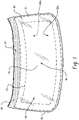
FIG. 1 shows a part that may receive a surface coating in accordance with the disclosed embodiments, where the part is an automobile window; -
FIG. 2 shows a stencil that may be applied to the part to facilitate applying the surface coating in accordance with the disclosed embodiments; -
FIG. 3 is a perspective view of a configuration of the stencil in accordance with the disclosed embodiments; -
FIG. 4 shows the stencil being positioned against a part prior to applying the surface coating in accordance with the disclosed embodiments; -
FIG. 5 is a flowchart showing a method of shielding a part from a coating application; -
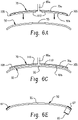
FIGS. 6A-6B respectively show side and perspective views of a stencil being placed against a part; -
FIGS. 6C-6D respectively show side and perspective views of a stencil that is placed against a part; and -
FIGS. 6E-6F respectively show side and perspective views of a part with a coating after a coating process is complete and the stencil is removed. -
FIG. 1 shows a part 50 (or final part), which may be for example a tailgate window for an automobile or the like. Thepart 50 may have a partouter side 50a, which may face an outside of a vehicle. Thepart 50 may have a partinner side 50b, which may face an interior cabin of a vehicle. Thepart 50 may be formed as a polycarbonate sheet or panel. - The
part 50 may be at least partially, or entirely, curved. For example, thepart 50 may be curved so that the partouter side 50a is generally concave while the partinner side 50b is generally convex. In some embodiments, thepart 50 may be formed with a part compound contour or profile. For example, thepart 50 may have a part center area 55 (or part first area) that extends transversely outward from apart center 56 to a part center area boundary 57 (or part first boundary) shown in dashed lines. As referenced herein an area of thepart 50 implies a surface area of thepart 50. In addition, as used herein, thepart 50 is formed as a curved sheet of material, and a transverse direction is along the sheet surface. - The
part center area 55 may define a part center area contour (or part first contour) that is non-planar. The part may have a part transition area 60 (or part second area) extending transversely outward from the partcenter area boundary 57 to a part transition area boundary 61 (or part second boundary) shown in dashed lines. As shown, thepart transition area 60 transversely surrounds thepart center area 55. Thepart transition area 60 may define a part transition area contour (or part second contour) that is non-planar and differs from the part center contour. For example, the part transition area contour may be more progressive than the part center contour. Thepart 50 may have a part perimeter area 65 (or part coatable area) extending transversely outward from the parttransition area boundary 61 to apart perimeter edge 66. As shown, thepart perimeter area 65 transversely surrounds thepart transition area 60. The identification of the boundaries and shapes are for purposes of facilitating a discussion of the embodiments and are not intended on limiting the disclosure. - There may be a desire to provide only the
part perimeter area 65, e.g., the part coatable area, with a surface coating 67 (referred to as a coating for simplicity). Thus, there may also be a desire to shield thepart center area 55 andpart transition area 60 from accepting the coating. However, there may be a challenge in securing a polycarbonate coating shield to thepart 50 over thepart center area 55 andpart transition area 60 being that theseareas -
FIG. 2 shows asystem 68 for shielding thepart 50 from a coating application. More specifically, astencil 70 that may be used to shield thepart center area 55 and thepart transition area 60 from being coated. Thestencil 70 may be formed as a polycarbonate sheet or panel. Thestencil 70 may have a stencil outer-side 70a (or coatable side) and astencil underside 70b (or vacuum side). During a coating process, thestencil 70 may be placed, or draped over thepart center area 55 andpart transition area 60, to act as a coating shield. In operation, the stencil outer-side 70a is subject to the coating while thestencil underside 70b, positioned against thepart 50, is shielded from the coating application. Thestencil 70 may be positioned against the partouter side 50a or partinner side 50b, depending on the coating requirement. Thus, depending on the application, one of the stencil outer-side 70a and thestencil underside 70b is generally concave while another of the stencil outer-side 70a and thestencil underside 70b is generally convex. - As with the
part 50, thestencil 70 may be formed with a stencil compound contour or profile that is shaped to conform with the shape of thepart 50. That is, thestencil 70 may have contour that is complimentary, e.g., matches the shape of thepart 50. More specifically, thestencil 70 may have a stencil center area 75 (or stencil first area) extending transversely outward from astencil center 76 to a stencil center area boundary 77 (or stencil first boundary) shown in a dashed line. As referenced herein an area of thestencil 70 implies a surface area of thestencil 70. Thestencil center area 75 may have a same size and shape as thewindow center area 55 and have a stencil center area contour (or stencil first contour) that is non-planar and is the same as the window center area contour. Thestencil 70 may have a stencil perimeter area 80 (or stencil second area) extending transversely outward from the stencilcenter area boundary 77 to astencil perimeter boundary 81 defining an outer edge. Thestencil perimeter area 80 may have a same size and shape as thepart transition area 60 and define a stencil perimeter area contour (or stencil second contour) that is non-planar and is the same as the part transition area contour. As shown, thestencil perimeter area 80 transversely surrounds thestencil center area 75. - The stencil compound contour may provide a shield to receiving the coating along the
part center area 55 andpart transition area 60. Thepart perimeter area 65 remains uncovered and may be coated. That is, thestencil 70 is configured to fit transversely within the parttransition area boundary 61 to transversely expose thepart perimeter area 65 that requires coating. As with thepart 50, thestencil 70, with its compound contour, is one example and is described for illustrative purposes only. - The
stencil 70 may be vacuum sealed against thepart 50 to prevent relative movement during the coating operation. To accomplish this, one ormore vacuum ports 85 may be formed or manufactured into thestencil 70 that are accessible from the stencil outer-side 70a. Thevacuum ports 85 fluidly communicate vacuum pressure between thestencil 70 and thepart 50 when thestencil 70 is disposed against thepart 50. As shown the one ormore vacuum ports 85 may include afirst vacuum port 85a located in thestencil center area 75 and asecond vacuum port 85b located in thestencil perimeter area 80. That is, thevacuum ports 85 may be distributed about thestencil 70 so that at least one of thevacuum ports 85 is located the different contour areas and/or so that thevacuum ports 85 are transversely spaced apart from each other. Having vacuum pressure ports respectively located in the plurality of contour areas in thestencil 70 helps evenly secure thestencil 70 to thepart 50. - Each of the first and
second vacuum ports second fittings side 70a. As shown, thefittings stencil 70 at the location where each respectively connects with thestencil 70. The first andsecond fittings second conduits second conduits stencil 70 and thepart 50. - To assist in sealing the
stencil 70 to thepart 50, aseal member 105 may be attached to thestencil underside 70b. Theseal member 105 may be, as one example, an o-ring. Theseal member 105 may be a foam seal tape. The foam seal tape is not particularly limited and can comprise at least one of a polyurethane, an ethylene propylene diene monomer rubber (EPDM), a silicone, or a polychloroprene (neoprene). Theseal member 105 may extend about thestencil perimeter area 80, e.g., transversely between the stencilcenter area boundary 77 and thestencil perimeter boundary 81. With the utilization of theseal member 105, a vacuum seal is achieved between thestencil 70 and thepart 50. - One or more gauge members 110 (or gauge blocks) may also be provided to the
stencil underside 70b. The illustrated embodiment includes fourgauge members 110a-110d distributed about thestencil underside 70b. Thegauge members 110a-110d are distributed about thestencil center area 75, though this is not intended on limiting the disclosure. Thegauge members 110 are configured for providing a predetermined amount of spacing between thestencil 70 and thepart 50, to enable the vacuum pressure to be evenly distributed within a sealing boundary defined by theseal member 105. Thegauge members 110 also prevent thepart 50 and thestencil 70 from contacting and potentially scratching thepart 50. It is to be appreciated that theseal member 105, distributed about thestencil 70, may be utilized in place of thegauge members 110, e.g., to provide for spacing between thestencil 70 and thepart 50. - In one embodiment, within the
stencil perimeter boundary 81, thestencil 70 may define astencil aperture 70c formed by a stencil aperture edge 70d. Thestencil aperture 70c may be transversely spaced apart from thevacuum port 85. To provide for the vacuum seal, theseal member 105 may include a sealmember perimeter portion 105a and a seal memberinternal portion 105b. The sealmember perimeter portion 105a and the seal memberinternal portion 105b may be transversely spaced apart from each other to allow for the vacuum pressure to be generated between thestencil 70 and thepart 50. The seal memberinternal portion 105b may have a same shape and be slightly larger than thestencil aperture 70c, and may closely surround thestencil aperture 70c, to maximize the vacuum pressure between thestencil 70 and thepart 50. In operation, the coating process may coat both thepart perimeter area 65 and an area of thepart 50 defined by thestencil aperture 70c. - As indicated, the contour of the stencil outer-
side 70a, which will be subject to receiving the coating, may be convex or concave, depending on a side of thepart 50 that is being coated.FIG. 3 shows an example where the stencil outer-side 70a is convex, and the first andsecond fittings ports stencil 70 may be utilized for positioning thestencil 70 against the partinner side 50b, which may be convex and face an interior cabin of a vehicle. In this embodiment, thestencil underside 70b, against which theseal member 105 is connected, is concave. -
FIG. 4 shows mounting of thestencil 70 shown inFIG. 3 to the partouter side 50a, though as indicated thestencil 70 could be configured for placement against the partinner side 50b. Thestencil 70 may be lifted and moved via theconduits fittings ports FIG. 4 is theseal member 105 and thegauge members 110a-110d. Once positioned against thepart 50, vacuum pressure may be applied to vacuum seal thestencil 70 in place. - Thus, as indicated, the
part 50 may be a sheet of material formed so that at least it is not planar. With this configuration thestencil 70 may be draped over, e.g., placed against, thepart 50 so that thestencil 70 is uniformly positioned adjacent to thepart 50. - Turning to
FIGS. 5 and6A-6F , a flowchart and accompanying illustrations show a method of shielding apart 50 from a coating application. As shown inblock 510 and in more detail inFIGS. 6A-6D , the method includes layering astencil 70 against a partfirst area 55 of apart 50 so that astencil vacuum side 70b of thestencil 70 faces the partfirst area 55 and a stencilcoatable side 70a of thestencil 70 faces away from the partfirst area 55. As indicated, the partfirst area 55 defines a part first contour that is non-planar. As further indicated, a stencilfirst area 75 of thestencil 70 defines a stencil first contour that is non-planar and conforms with the partfirst area 55. From this configuration, thestencil vacuum side 70b is uniformly positioned adjacent to thepart 50. - As shown in
block 520, while in the configuration shown inFIGS. 6C-6D , the method includes fluidly communicating vacuum pressure between thestencil 70 and thepart 50 via afirst vacuum port 85a formed in thestencil 70. Thefirst vacuum port 85a is accessible from the stencilcoatable side 70a. This configuration forms a vacuum seal between thestencil 70 and thepart 50. - As shown in
block 530, while in the configuration shown inFIGS. 6C-6D , the method includes applying asurface coating 67 to thepart 50 so that thesurface coating 67 is received over apart coatable area 65 of thepart 50 that exposed by thestencil coatable side 70. - As shown in
block 540, the method includes curing thesurface coating 67 after applying thesurface coating 67. As shown inblock 550 andFIGS. 6E-6F , the method includes removing thestencil 70. From this configuration, thesurface coating 67 covers thepart coatable area 65, and the partfirst area 55 is free of thesurface coating 67. - The above blocks 510-550 identify various aspects of the method of the disclosed embodiments. Additional aspects of the embodiments are now identified, with continued reference to
FIGS. 5 and6A-6F . These additional aspects are neither intended on limiting the scope of the embodiments and nor intended to imply a particular sequence of performance unless expressly indicated. - As shown in
block 560 andFIGS. 6A-6D , though in more detail inFIGS. 6A and 6C , the method includes seating thestencil 70 against the partfirst area 55 via aseal member 105 extending about thestencil vacuum side 70b. As shown inblock 570, the method includes positioning thestencil 70 against the partfirst area 55 via one ormore gauge members stencil vacuum side 70b and thepart 50. As shown inblock 580, the method includes fluidly communicating the vacuum pressure between thestencil 70 and thepart 50 via afirst vacuum port 85a that is formed in the stencilfirst area 75. - As shown in
block 590, the method includes fluidly communicating the vacuum pressure between thestencil 70 and thepart 50 via asecond vacuum port 85b formed in a stencilsecond area 80 of thestencil 70. As indicated, the stencilsecond area 80 defines a stencil second contour that is non-planar and conforms with a partsecond area 60 of thepart 50 that is non-planar. As indicated, the stencil first contour and stencil second contour differ from each other. - As shown in
block 600, the method includes applying thesurface coating 67 by air brushing one or more of bonding ink, paint and powder against the stencilcoatable side 70a and thepart coatable area 65. With regard to a powder coating application, thepart 50 may be positively charged while a powder spraying apparatus may be negatively charged to attract powder to the part. As shown inblock 610, the method includes forming thestencil 70, prior to laying thestencil 70 on the partfirst area 55, so that the stencilfirst area 75 defines the stencil first contour that is non-planar and conforms with the part first contour of the partfirst area 55. As shown inblock 620, the method includes forming thestencil 70 and thepart 50 as respective polycarbonate sheets. - The part and/or stencil, or a combination thereof, can comprise a polymeric material. The polymeric material is chosen based upon the desired part properties, such as transparency and thermal stability. Examples of polymeric materials include, but are not limited to, polyesters, polycarbonates, polystyrenes (e.g., copolymers of polycarbonate and styrene, polyphenylene ether-polystyrene blends), polyimides (e.g., polyetherimides), acrylonitrile-styrene-butadiene (ABS), polyarylates, polyalkylmethacrylates (e.g., polymethylmethacrylates (PMMA)), polyolefins (e.g., polypropylenes (PP) and polyethylenes, high density polyethylenes (HDPE), low density polyethylenes (LDPE), linear low density polyethylenes (LLDPE)), polyamides (e.g., polyamideimides), polyarylates, polysulfones (e.g., polyarylsulfones, polysulfonamides), polyphenylene sulfides, polytetrafluoroethylenes, polyethers (e.g., polyether ketones (PEK), polyether etherketones (PEEK), polyethersulfones (PES)), polyacrylics, polyacetals, polybenzoxazoles (e.g., polybenzothiazinophenothiazines, polybenzothiazoles), polyoxadiazoles, polypyrazinoquinoxalines, polypyromellitimides, polyquinoxalines, polybenzimidazoles, polyoxindoles, polyoxoisoindolines (e.g., polydioxoisoindolines), polytriazines, polypyridazines, polypiperazines, polypyridines, polypiperidines, polytriazoles, polypyrazoles, polypyrrolidones, polycarboranes, polyoxabicyclononanes, polydibenzofurans, polyphthalamide, polyacetals, polyanhydrides, polyvinyls (e.g., polyvinyl ethers, polyvinyl thioethers, polyvinyl alcohols, polyvinyl ketones, polyvinyl halides, polyvinyl nitriles, polyvinyl esters, polyvinylchlorides), polysulfonates, polysulfides, polyureas, polyphosphazenes, polysilazanes, polysiloxanes, fluoropolymers (e.g., polyvinyl fluoride (PVF), polyvinylidene fluoride (PVDF), polyvinyl fluoride (PVF), fluorinated ethylene-propylene (FEP), polyethylene tetrafluoroethylene (ETFE)), polycarbonate-siloxane block copolymer (such as LEXAN™ EXL Resin), terephthalate ester of resorcinol (ITR) (such as LEXAN™ SLX Resin), N-phenylphenol phthaleinylbisphenol (PPP-BP) (such as LEXAN™ XHT Resin), or a combination comprising at least one of the foregoing.
- The part and/or stencil, or a combination thereof, can comprise a polymeric material. The thermoplastic polymer can also comprise a polyester. Polyesters include those derived from an aliphatic, cycloaliphatic, or aromatic diol, or mixtures thereof, containing from 2 to about 10 carbon atoms and an aliphatic, cycloaliphatic, or aromatic dicarboxylic acid, and have repeating units of the following general formula:

- wherein n is an integer of from 2 to 6, and R1 and R2 are each independently a divalent C1-C20 aliphatic radical, a C2-C12 cycloaliphatic alkyl radical, or a C6-C24 aromatic radical. The polyesters can be formed from terephthalic acid and a combination of ethylene glycol and cyclohexadimethanol, for example, formed from terephthalic acid and a combination of ethylene glycol, diethylene glycol and cyclohexadimethanol. Examples of polyesters include at least one of poly(ethylene terephthalate), spiroglycol modified polyethylene terephthalate, polycyclohexylenedimethylene terephthalate glycol, poly(1,4-cyclohexylenedimethylene 1,4-cyclohexanedicarboxylate), and polyethyelene naphthalate, poly-cyclohexylenedimethylene-terephthalate-glycol, polycyclohexylenedimethylene terephthalate, or polyethylene terephthalate with diethylene glycol. The polyester can comprises poly(ethylene terephthalate) ("PET"), e.g., unmodified PET. The polyester can comprise spiroglycol modified amorphous PET.
- The part and/or stencil, or a combination thereof, can comprise a single layer, e.g., a monolithic sheet. Optionally, the part and/or stencil, or a combination thereof, can be formed of a plurality of layers. For example, the thermoplastic polymer can comprise a plurality of layers greater than or equal to 4 layers, for instance, greater than or equal to 32 layers, greater than or equal to 67 layers. The total number of layers can be 8 to 512 layers, or 32 to 128 layers. The plurality of layers of the thermoplastic polymer can include less than or equal to 512 layers, or less than or equal to 256 layers, for example, less than or equal to 128 layers.
- The part and/or stencil, or a combination thereof, can comprise a thermoplastic sheet which is co-extruded, coated, laminated, or a combination comprising at least one of the foregoing. For example, the part and/or stencil, or a combination thereof, can comprise a polycarbonate core with a co-extruded PMMA layer, a polycarbonate sheet with a silica hard coat, a polycarbonate laminated with a transparent film such as polyvinylidene fluoride (PVDF), other transparent polymer films, or a combination comprising at least one of the foregoing.
- The system disclosed herein include(s) at least one of the following aspects:
- Aspect 1: A method of shielding a part from a coating application, comprising: layering a
stencil 70 against a partfirst area 55 of apart 50 so that astencil vacuum side 70b of thestencil 70 faces the partfirst area 55 and a stencilcoatable side 70a of thestencil 70 faces away from the partfirst area 55, wherein the partfirst area 55 defines a part first contour that is non-planar, and wherein a stencilfirst area 75 of thestencil 70 defines a stencil first contour that is non-planar and conforms with the partfirst area 55, whereby thestencil vacuum side 70b is uniformly positioned adjacent to thepart 50; fluidly communicating vacuum pressure between thestencil 70 and thepart 50 via afirst vacuum port 85a formed in thestencil 70, wherein thefirst vacuum port 85a is accessible from the stencilcoatable side 70a, thereby forming a vacuum seal between thestencil 70 and thepart 50; and applying asurface coating 67 to thepart 50 so that thesurface coating 67 is received over apart coatable area 65 of thepart 50 that is exposed by the stencilcoatable side 70a - Aspect 2: The method of aspect 1, comprising: curing the
surface coating 67 after applying thesurface coating 67. - Aspect 3: The method of aspects 1 or 2, comprising: removing the
stencil 70, whereby thesurface coating 67 covers thepart coatable area 65, and the partfirst area 55 is free of thesurface coating 67. - Aspect 4: The method of any of aspects 1 to 3, comprising: seating the
stencil 70 against the partfirst area 55 via aseal member 105 extending about thestencil vacuum side 70b. - Aspect 5: The method of any of aspects 1 to 4, comprising: positioning the
stencil 70 against the partfirst area 55 via one ormore gauge members stencil vacuum side 70b and thepart 50. - Aspect 6: The method of any of aspects 1 to 5, comprising: fluidly communicating the vacuum pressure between the
stencil 70 and thepart 50 via thefirst vacuum port 85a that is formed in the stencilfirst area 75; and fluidly communicating the vacuum pressure between thestencil 70 and thepart 50 via asecond vacuum port 85b formed in a stencilsecond area 80 of thestencil 70, wherein the stencilsecond area 80 defines a stencil second contour that is non-planar and conforms with a partsecond area 60 of thepart 50, wherein the partsecond area 60 defines part second contour that is non-planar, and wherein the stencil first contour and the stencil second contour differ from each other. - Aspect 7: The method of any one of aspects 1 to 6, comprising: applying the
surface coating 67 by air brushing one or more of bonding ink, paint and powder against the stencilcoatable side 70a and thepart coatable area 65. - Aspect 8: The method of any of aspects 1 to 7, comprising: forming the
stencil 70, prior to laying thestencil 70 on the partfirst area 55, so that the stencilfirst area 75 defines the stencil first contour that is non-planar and conforms with the part first contour of the partfirst area 55. - Aspect 9: The method of any of aspects 1 to 8, comprising: forming the
stencil 70 and thepart 50 as respective polycarbonate sheets. - Aspect 10: A system for shielding a part from a coating application, the system comprising: a
stencil 70 configured to be layered against a partfirst area 55 of thepart 50 so that astencil vacuum side 70b of thestencil 70 faces the partfirst area 55 and a stencilcoatable side 70a of thestencil 70 faces away from the partfirst area 55, wherein the partfirst area 55 defines a part first contour that is non-planar, wherein a stencilfirst area 75 of thestencil 70 defines a stencil first contour that is non-planar and conforms with the part first contour of the partfirst area 55, whereby thestencil vacuum side 70b is configured to be uniformly positioned adjacent to thepart 50; afirst vacuum port 85a formed in thestencil 70 is configured to fluidly communicate vacuum pressure between thestencil 70 and thepart 50 when thestencil 70 is disposed against thepart 50, wherein thefirst vacuum port 85a is accessible from the stencilcoatable side 70a and configured form a vacuum seal between thestencil 70 and thepart 50. - Aspect 11: The system of aspect 10, wherein: the
first vacuum port 85a is formed in the stencilfirst area 75; and a second vacuum port 220 is formed in a stencilsecond area 80 of thestencil 70, wherein the stencilsecond area 80 defines a stencil second contour that is non-planar and conforms with a partsecond area 60 of thepart 50 that is non-planar, and wherein the stencil first contour and stencil second contour differ from each other. - Aspect 12: The system of aspects 10 or 11, comprising: a
seal member 105 extending about thestencil vacuum side 70b. - Aspect 13: The system of any of aspects 10 to 12, comprising: one or
more gauge members stencil vacuum side 70b and configured for positioning thestencil 70 against the partfirst area 55. - Aspect 14: The system of any of aspects 10 to 13, wherein the
stencil 70 and thepart 50 are respective polycarbonate sheets. - Aspect 15: The system of any of aspects 10 to 14, wherein the
stencil 70 defines astencil aperture 70c formed by a stencil aperture edge 70d, wherein thestencil aperture 70c is spaced apart from thevacuum port 85; and theseal member 105 defines a sealmember perimeter portion 105a positioned about astencil perimeter boundary 81 and a seal memberinternal portion 105b positioned about thestencil aperture 70c. - In general, the invention may alternately comprise, consist of, or consist essentially of, any appropriate components herein disclosed. The invention may additionally, or alternatively, be formulated so as to be devoid, or substantially free, of any components, materials, ingredients, adjuvants or species used in the prior art compositions or that are otherwise not necessary to the achievement of the function and/or objectives of the present invention. The endpoints of all ranges directed to the same component or property are inclusive and independently combinable (e.g., ranges of "less than or equal to 25 wt%, or 5 wt% to 20 wt%," is inclusive of the endpoints and all intermediate values of the ranges of "5 wt% to 25 wt%," etc.). Disclosure of a narrower range or more specific group in addition to a broader range is not a disclaimer of the broader range or larger group. "Combination" is inclusive of blends, mixtures, alloys, reaction products, and the like. Furthermore, the terms "first," "second," and the like, herein do not denote any order, quantity, or importance, but rather are used to denote one element from another. The terms "a" and "an" and "the" herein do not denote a limitation of quantity, and are to be construed to cover both the singular and the plural, unless otherwise indicated herein or clearly contradicted by context. "Or" means "and/or." The suffix "(s)" as used herein is intended to include both the singular and the plural of the term that it modifies, thereby including one or more of that term (e.g., the film(s) includes one or more films). Reference throughout the specification to "one embodiment", "another embodiment", "an embodiment", and so forth, means that a particular element (e.g., feature, structure, and/or characteristic) described in connection with the embodiment is included in at least one embodiment described herein, and may or may not be present in other embodiments. In addition, it is to be understood that the described elements may be combined in any suitable manner in the various embodiments.
- The modifier "about" used in connection with a quantity is inclusive of the stated value and has the meaning dictated by the context (e.g., includes the degree of error associated with measurement of the particular quantity). The notation "+ 10%" means that the indicated measurement can be from an amount that is minus 10% to an amount that is plus 10% of the stated value. The terms "front", "back", "bottom", and/or "top" are used herein, unless otherwise noted, merely for convenience of description, and are not limited to any one position or spatial orientation. "Optional" or "optionally" means that the subsequently described event or circumstance can or cannot occur, and that the description includes instances where the event occurs and instances where it does not. Unless defined otherwise, technical and scientific terms used herein have the same meaning as is commonly understood by one of skill in the art to which this invention belongs. A "combination" is inclusive of blends, mixtures, alloys, reaction products, and the like.
- All cited patents, patent applications, and other references are incorporated herein by reference in their entirety. However, if a term in the present application contradicts or conflicts with a term in the incorporated reference, the term from the present application takes precedence over the conflicting term from the incorporated reference.
- While particular embodiments have been described, alternatives, modifications, variations, improvements, and substantial equivalents that are or may be presently unforeseen may arise to applicants or others skilled in the art. Accordingly, the appended claims as filed and as they may be amended are intended to embrace all such alternatives, modifications variations, improvements, and substantial equivalents.
Claims (15)
- A method of shielding a part from a coating application, comprising:layering a stencil 70 against a part first area 55 of the part 50 so that a stencil vacuum side 70b of the stencil 70 faces the part first area 55 and a stencil coatable side 70a of the stencil 70 faces away from the part first area 55,wherein the part first area 55 defines a part first contour that is non-planar, and wherein a stencil first area 75 of the stencil 70 defines a stencil first contour that is non-planar and conforms with the part first area 55, whereby the stencil vacuum side 70b is uniformly positioned adjacent to the part 50;fluidly communicating vacuum pressure between the stencil 70 and the part 50 via a first vacuum port 85a formed in the stencil 70, wherein the first vacuum port 85a is accessible from the stencil coatable side 70a, thereby forming a vacuum seal between the stencil 70 and the part 50; andapplying a surface coating 67 to the part 50 so that the surface coating 67 is received over a part coatable area 65 of the part 50 that is exposed by the stencil coatable side 70a.
- The method of claim 1, comprising:
curing the surface coating 67 after applying the surface coating 67. - The method of claims 1 or 2, comprising:removing the stencil 70,whereby the surface coating 67 covers the part coatable area 65, and the part first area 55 is free of the surface coating 67.
- The method of any of claims 1 to 3, comprising:
seating the stencil 70 against the part first area 55 via a seal member 105 extending about the stencil vacuum side 70b. - The method of any of claims 1 to 4, comprising:
positioning the stencil 70 against the part first area 55 via one or more gauge members 110a, 110b located between the stencil vacuum side 70b and the part 50. - The method of any of claims 1 to 5, comprising:fluidly communicating the vacuum pressure between the stencil 70 and the part 50 via the first vacuum port 85a that is formed in the stencil first area 75; andfluidly communicating the vacuum pressure between the stencil 70 and the part 50 via a second vacuum port 85b formed in a stencil second area 80 of the stencil 70,wherein the stencil second area 80 defines a stencil second contour that is non-planar and conforms with a part second area 60 of the part 50, wherein the part second area 60 defines a part second contour that is non-planar, andwherein the stencil first contour and the stencil second contour differ from each other.
- The method of any one of claims 1 to 6, comprising:
applying the surface coating 67 by air brushing one or more of bonding ink, paint and powder against the stencil coatable side 70a and the part coatable area 65. - The method of any of claims 1 to 7, comprising:forming the stencil 70, prior to laying the stencil 70 on the part first area 55,so that the stencil first area 75 defines the stencil first contour that is non-planar and conforms with the part first contour of the part first area 55.
- The method of any of claims 1 to 8, comprising:
forming the stencil 70 and the part 50 as respective polycarbonate sheets. - A system for shielding a part from a coating application, the system comprising:a stencil 70 configured to be layered against a part first area 55 of the part 50 so that a stencil vacuum side 70b of the stencil 70 faces the part first area 55 and a stencil coatable side 70a of the stencil 70 faces away from the part first area 55, wherein the part first area 55 defines a part first contour that is non-planar,wherein a stencil first area 75 of the stencil 70 defines a stencil first contour that is non-planar and conforms with the part first contour of the part first area 55, whereby the stencil vacuum side 70b is configured to be uniformly positioned adjacent to the part 50; anda first vacuum port 85a formed in the stencil 70 is configured to fluidly communicate vacuum pressure between the stencil 70 and the part 50 when the stencil 70 is disposed against the part 50, wherein the first vacuum port 85a is accessible from the stencil coatable side 70a and configured form a vacuum seal between the stencil 70 and the part 50.
- The system of claim 10, wherein:the first vacuum port 85a is formed in the stencil first area 75; anda second vacuum port 220 is formed in a stencil second area 80 of the stencil 70,wherein the stencil second area 80 defines a stencil second contour that is non-planar and conforms with a part second area 60 of the part 50 that is non-planar, andwherein the stencil first contour and stencil second contour differ from each other.
- The system of claims 10 or 11, comprising:
a seal member 105 extending about the stencil vacuum side 70b. - The system of any of claims 10 to 12, comprising:
one or more gauge members 110a, 110b located against the stencil vacuum side 70b and configured for positioning the stencil 70 against the part first area 55. - The system of any of claims 10 to 13, wherein the stencil 70 and the part 50 are respective polycarbonate sheets.
- The system of any of claims 10 to 14, wherein:the stencil 70 defines a stencil aperture 70c formed by a stencil aperture edge 70d,wherein the stencil aperture 70c is spaced apart from the vacuum port 85; andthe seal member 105 defines a seal member perimeter portion 105a positioned about a stencil perimeter boundary 81 and a seal member internal portion 105b positioned about the stencil aperture 70c.
Priority Applications (2)
| Application Number | Priority Date | Filing Date | Title |
|---|---|---|---|
| EP20200320.8A EP3981570A1 (en) | 2020-10-06 | 2020-10-06 | System and method of shielding a part from a coating application |
| PCT/EP2021/077434 WO2022073998A1 (en) | 2020-10-06 | 2021-10-05 | System and method of shielding a part from a coating application |
Applications Claiming Priority (1)
| Application Number | Priority Date | Filing Date | Title |
|---|---|---|---|
| EP20200320.8A EP3981570A1 (en) | 2020-10-06 | 2020-10-06 | System and method of shielding a part from a coating application |
Publications (1)
| Publication Number | Publication Date |
|---|---|
| EP3981570A1 true EP3981570A1 (en) | 2022-04-13 |
Family
ID=72752796
Family Applications (1)
| Application Number | Title | Priority Date | Filing Date |
|---|---|---|---|
| EP20200320.8A Withdrawn EP3981570A1 (en) | 2020-10-06 | 2020-10-06 | System and method of shielding a part from a coating application |
Country Status (2)
| Country | Link |
|---|---|
| EP (1) | EP3981570A1 (en) |
| WO (1) | WO2022073998A1 (en) |
Citations (4)
| Publication number | Priority date | Publication date | Assignee | Title |
|---|---|---|---|---|
| JPH068799A (en) * | 1992-06-24 | 1994-01-18 | Asahi Glass Co Ltd | Windshield glass for automobile |
| JPH0661527U (en) * | 1993-02-08 | 1994-08-30 | 日本板硝子株式会社 | Resin window for vehicle |
| WO1994020223A1 (en) * | 1989-01-05 | 1994-09-15 | Tamglass Engineering Oy | Method and system for applying a marking to a substrate, particularly a painted border adjacent to and around a windshield plate |
| JPH07292476A (en) * | 1994-04-21 | 1995-11-07 | Asahi Glass Co Ltd | Method and apparatus for film formation on one side of plate |
-
2020
- 2020-10-06 EP EP20200320.8A patent/EP3981570A1/en not_active Withdrawn
-
2021
- 2021-10-05 WO PCT/EP2021/077434 patent/WO2022073998A1/en not_active Ceased
Patent Citations (4)
| Publication number | Priority date | Publication date | Assignee | Title |
|---|---|---|---|---|
| WO1994020223A1 (en) * | 1989-01-05 | 1994-09-15 | Tamglass Engineering Oy | Method and system for applying a marking to a substrate, particularly a painted border adjacent to and around a windshield plate |
| JPH068799A (en) * | 1992-06-24 | 1994-01-18 | Asahi Glass Co Ltd | Windshield glass for automobile |
| JPH0661527U (en) * | 1993-02-08 | 1994-08-30 | 日本板硝子株式会社 | Resin window for vehicle |
| JPH07292476A (en) * | 1994-04-21 | 1995-11-07 | Asahi Glass Co Ltd | Method and apparatus for film formation on one side of plate |
Also Published As
| Publication number | Publication date |
|---|---|
| WO2022073998A1 (en) | 2022-04-14 |
Similar Documents
| Publication | Publication Date | Title |
|---|---|---|
| US5492750A (en) | Mask for coated glass | |
| EP0251546B1 (en) | Making automobile body panels having applied painted carrier films | |
| EP0060556B1 (en) | Reinforcing material | |
| US5919537A (en) | Decorative films and laminated formable sheets with dual protective film layers | |
| WO2008153484A1 (en) | Method for fastening a windowpane | |
| US5620648A (en) | Process for the preparation of prefabricated vehicle windows | |
| EP2401462B1 (en) | Mechanically stiffened weatherseal carrier | |
| US20140292029A1 (en) | Insert with integrated fastener | |
| US20180345773A1 (en) | Glazing with inbuilt profile section | |
| KR20010079791A (en) | Reusable mask and method for coating substrate | |
| US5330597A (en) | Process for the preparation of a vehicle window | |
| US4338148A (en) | Method of manufacturing a door edge guard | |
| WO2022073998A1 (en) | System and method of shielding a part from a coating application | |
| GB2048777A (en) | Belt and methods of manufacture and splicing | |
| JP3220457B2 (en) | Release profiles for use in lacquering automotive bodies | |
| EP3845366A1 (en) | Molding system and methods for forming structures | |
| CN113928534A (en) | Guide rail for an aircraft floor, aircraft and method for producing a guide rail | |
| US6031184A (en) | Flexible wire harness with a predetermined path | |
| US11691490B2 (en) | Seal assembly | |
| KR100242854B1 (en) | Vacuum laminating apparatus and method | |
| US4798130A (en) | Door water deflector and vent | |
| US7311936B2 (en) | Integral skin interior trim | |
| US20220170165A1 (en) | Method for applying a corrosion protection layer to a surface to be protected of a component | |
| JPH06171358A (en) | Vehicle resin window structure | |
| CN223443290U (en) | Glass edge-covering assembly, forming die thereof and vehicle |
Legal Events
| Date | Code | Title | Description |
|---|---|---|---|
| PUAI | Public reference made under article 153(3) epc to a published international application that has entered the european phase |
Free format text: ORIGINAL CODE: 0009012 |
|
| STAA | Information on the status of an ep patent application or granted ep patent |
Free format text: STATUS: THE APPLICATION HAS BEEN PUBLISHED |
|
| AK | Designated contracting states |
Kind code of ref document: A1 Designated state(s): AL AT BE BG CH CY CZ DE DK EE ES FI FR GB GR HR HU IE IS IT LI LT LU LV MC MK MT NL NO PL PT RO RS SE SI SK SM TR |
|
| STAA | Information on the status of an ep patent application or granted ep patent |
Free format text: STATUS: REQUEST FOR EXAMINATION WAS MADE |
|
| 17P | Request for examination filed |
Effective date: 20220420 |
|
| RBV | Designated contracting states (corrected) |
Designated state(s): AL AT BE BG CH CY CZ DE DK EE ES FI FR GB GR HR HU IE IS IT LI LT LU LV MC MK MT NL NO PL PT RO RS SE SI SK SM TR |
|
| STAA | Information on the status of an ep patent application or granted ep patent |
Free format text: STATUS: THE APPLICATION IS DEEMED TO BE WITHDRAWN |
|
| 18D | Application deemed to be withdrawn |
Effective date: 20221014 |