EP3981561A1 - Tactile sensor, robot hand, and robot - Google Patents
Tactile sensor, robot hand, and robot Download PDFInfo
- Publication number
- EP3981561A1 EP3981561A1 EP19932180.3A EP19932180A EP3981561A1 EP 3981561 A1 EP3981561 A1 EP 3981561A1 EP 19932180 A EP19932180 A EP 19932180A EP 3981561 A1 EP3981561 A1 EP 3981561A1
- Authority
- EP
- European Patent Office
- Prior art keywords
- face
- side face
- base portion
- cover
- covering portion
- Prior art date
- Legal status (The legal status is an assumption and is not a legal conclusion. Google has not performed a legal analysis and makes no representation as to the accuracy of the status listed.)
- Withdrawn
Links
Images




Classifications
-
- B—PERFORMING OPERATIONS; TRANSPORTING
- B25—HAND TOOLS; PORTABLE POWER-DRIVEN TOOLS; MANIPULATORS
- B25J—MANIPULATORS; CHAMBERS PROVIDED WITH MANIPULATION DEVICES
- B25J13/00—Controls for manipulators
- B25J13/08—Controls for manipulators by means of sensing devices, e.g. viewing or touching devices
- B25J13/081—Touching devices, e.g. pressure-sensitive
- B25J13/082—Grasping-force detectors
-
- B—PERFORMING OPERATIONS; TRANSPORTING
- B25—HAND TOOLS; PORTABLE POWER-DRIVEN TOOLS; MANIPULATORS
- B25J—MANIPULATORS; CHAMBERS PROVIDED WITH MANIPULATION DEVICES
- B25J13/00—Controls for manipulators
- B25J13/08—Controls for manipulators by means of sensing devices, e.g. viewing or touching devices
- B25J13/081—Touching devices, e.g. pressure-sensitive
- B25J13/084—Tactile sensors
-
- B—PERFORMING OPERATIONS; TRANSPORTING
- B25—HAND TOOLS; PORTABLE POWER-DRIVEN TOOLS; MANIPULATORS
- B25J—MANIPULATORS; CHAMBERS PROVIDED WITH MANIPULATION DEVICES
- B25J15/00—Gripping heads and other end effectors
- B25J15/08—Gripping heads and other end effectors having finger members
-
- G—PHYSICS
- G01—MEASURING; TESTING
- G01L—MEASURING FORCE, STRESS, TORQUE, WORK, MECHANICAL POWER, MECHANICAL EFFICIENCY, OR FLUID PRESSURE
- G01L5/00—Apparatus for, or methods of, measuring force, work, mechanical power, or torque, specially adapted for specific purposes
- G01L5/22—Apparatus for, or methods of, measuring force, work, mechanical power, or torque, specially adapted for specific purposes for measuring the force applied to control members, e.g. control members of vehicles, triggers
- G01L5/226—Apparatus for, or methods of, measuring force, work, mechanical power, or torque, specially adapted for specific purposes for measuring the force applied to control members, e.g. control members of vehicles, triggers to manipulators, e.g. the force due to gripping
Definitions
- the present disclosure relates to a tactile sensor, a robot hand, and a robot.
- the multiaxial force sensor includes a sensor unit that has plural pressure sensors and a cover that covers the sensor unit. External forces input to the cover are transmitted to the pressure sensors of the sensor unit.
- the cover becomes largely displaced, at the position to which the external force is input, in a direction toward a base portion. Meanwhile, the part of the cover away from the position where the external force is input becomes largely displaced in a direction away from the base portion.
- a tactile sensor of the present disclosure includes a cover that is provided so as to cover at least part of a base portion, a detection unit that is disposed between the cover and the base portion and detects force applied to the cover, and a limiting structure that limits inclination of the cover with respect to the base portion.
- failures can be inhibited regardless of the position where force is applied to a cover.
- a first embodiment will be described below with reference to FIG. 1 to FIG. 3 .
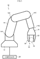
- FIG. 1 is a diagram showing a robot 10 pertaining to this embodiment.
- the robot 10 includes a robot body 12, a robot arm 14 that extends from the robot body 12, and a robot hand 16 that is provided on a distal end of the robot arm 14.
- the robot arm 14 is supported by the robot body 12 via a first joint 14A, and the robot arm 14 can rotate and bend with respect to the robot body 12. Furthermore, the robot arm 14 includes a second joint 14B and a third joint 14C and can bend in arbitrary directions at each of the joints 14B, 14C.
- the robot hand 16 is supported by the robot arm 14 via a fourth joint 14D, and the robot hand 16 can rotate and bend with respect to the robot arm 14.
- the robot hand 16 includes a first finger 20 and a second finger 22, which are disposed opposing each other, and can hold an object 24 between the two fingers 20, 22.
- the first finger 20 is equipped with a tactile sensor 26, and the second finger 22 configures an opposing member that opposes the first finger 20 equipped with the tactile sensor 26.
- a controller 28 is connected to the robot body 12.
- the robot body 12 outputs drive signals to actuators of the robot arm 14 and the robot hand 16 based on control signals from the controller 28 to drive the robot arm 14 and the robot hand 16.
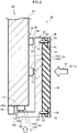
- FIG. 2 is a sectional view of main parts showing the first finger 20, and a base portion 30 configuring the first finger 20 applies gripping force according to relative displacement of the two fingers 20, 22 to the object 24 when it grips the object 24 together with the second finger 22 (see FIG. 1 ).
- the base portion 30 is equipped with the tactile sensor 26.
- the tactile sensor 26 includes a cover 32, which is provided so as to cover at least part of the base portion 30, and a detection unit (detailed below), which is disposed between the cover 32 and the base portion 30 and detects force F1 applied to the cover 32. Furthermore, the tactile sensor 26 includes a limiting structure 34 that limits inclination of the cover 32 with respect to the base portion 30. Additionally, a contact portion 36 that contacts a target place of the object 24 is replaceably attached to the cover 32.
- the cover 32 has a side face covering portion 40 that is disposed along a base portion side face 38, which is a face of the base portion 30 positioned on the second finger 22 side, and an end face covering portion 44 that extends from the distal end of the side face covering portion 40 and is disposed along a base portion end face 42 on the distal end side of the base portion 30.
- the cover 32 is configured by a stainless steel plate as an example.
- the cover 32 may also be configured by, for example, an acrylic plate.
- the side face covering portion 40 and the end face covering portion 44 are formed as rectangular plates, which is an arbitrary shape, and the cover 32 is L-shaped in cross section.
- the shape of the side face covering portion 40 and the end face covering portion 44 is not limited to a rectangular shape and may also be another shape.
- the detection unit includes a side face detection unit 50 provided between the base portion side face 38 and the side face covering portion 40 and an end face detection unit 52 provided between the base portion end face 42 and the end face covering portion 44.
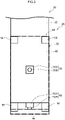
- the side face detection unit 50 is disposed in a place corresponding to the central portion of the side face covering portion 40 when viewed from the second finger 22 side
- the end face detection unit 52 is disposed in a place corresponding to the width direction central portion of the end face covering portion 44.
- a plurality of the side face detection units 50 may be provided between the base portion side face 38 and the side face covering portion 40 and that a plurality of the end face detection units 52 may be provided between the base portion end face 42 and the end face covering portion 44.
- the side face detection unit 50 and the end face detection unit 52 detect applied forces F1, F2 as electrical changes and transmit the detected electrical changes to the controller 28 via a harness not shown in the drawings.
- Examples of electrical changes include a change in capacitance, a change in resistance value, a change in current, a change in inductance, a charge transfer, and a change in resonance frequency.
- the two detection units 50, 52 are configured by sensors, and the sensors can be called load sensors or force sensors.
- the two detection units 50, 52 have identical configurations, and include rectangular sensor bodies 50A, 52A and cylindrical contacts 50B, 52B that project from the sensor bodies 50A, 52A. It will be noted that the two detection units 50, 52 may be different types of detection units and may be detection units with different measurement ranges.
- the sensor body 50A of the side face detection unit 50 is fixed to the base portion side face 38, and the distal end of the contact 50B of the side face detection unit 50 is adhered to the side face covering portion 40 of the cover 32.
- the sensor body 52A of the end face detection unit 52 is fixed to the base portion end face 42, and the distal end of the contact 52B of the end face detection unit 52 is adhered to the end face covering portion 44 of the cover 32. Because of this, the cover 32 is supported by the base portion 30 via the detection units 50, 52, and the side face covering portion 40 and the end face covering portion 44 can be integrally displaced with respect to the base portion 30.
- the contacts 50B, 52B of the detection units 50, 52 are configured to retract toward the sensor bodies 50A, 52A in accordance with the applied forces F1, F2 as an example, and the forces F1, F2 applied to the contacts 50B, 52B are measured from the amount of retraction of the contacts 50B, 52B. Because of this, the detection units 50, 52 detect the forces F1, F2 applied to the cover 32 from the relative displacement of the cover 32 with respect to the base portion 30.
- the limiting structure 34 is configured by stoppers that limit movement of the cover 32 in a direction toward the base portion 30.
- the stoppers are disposed so as to surround the side face detection unit 50 and are disposed in the four corners of the side face covering portion 40. Because of this, the stoppers limit movement of the peripheral edge portion of the cover 32, and the stoppers share and receive, with the side face detection unit 50, the forces F1, F2 before an overload is applied to the tactile sensor 26.
- the stoppers include side face stoppers 54 provided on the base portion side face 38 and end face stoppers 56 provided on the base portion end face 42.
- the side face stoppers 54 are fixed to the base portion 30, but they may also be fixed to the cover 32.
- a distance dimension R1 from end faces 54A of the side face stoppers 54 to the side face covering portion 40 is smaller than a projection dimension T1 by which the contact 50B projects from the sensor body 50A when a rated load is applied to the side face detection unit 50.
- a distance dimension R2 from side faces 56A of the end face stoppers 56 to an end face 44B of the end face covering portion 44 is smaller than the projection dimension T1 by which the contact 50B projects from the sensor body 50A when the rated load is applied to the side face detection unit 50.
- the side face stoppers 54 are disposed in places opposing the two corner portions of the side face covering portion 40 on the robot arm 14 side, and the rectangular side face covering portion 40 can hit the side face stoppers 54 at two places on the base end side of the base portion 30.
- the end face stoppers 56 are disposed in places opposing both length direction end portions of the end face 44B of the end face covering portion 44, and the rectangular side face covering portion 40 can hit the end face stoppers 56 via the end face covering portion 44 at two places on the distal end side of the base portion 30.
- the contact portion 36 is configured by a rubber material formed in a tabular shape, and the contact portion 36 mitigates impact and shock between the first finger 20 and the object 24 when the first finger 20 and the second finger 22 grip the object 24.
- Recessed portions 58 are formed in the four corners of the contact portion 36, and through holes 60 that penetrate to the reverse face are formed in bottom surfaces of the recessed portions 58.
- Screw holes 62 are formed in places in the side face covering portion 40 corresponding to the through holes 60, and screws 64 inserted into the through holes 60 in the contact portion 36 are screwed into the screw holes 62, whereby the contact portion 36 can be replaceably attached to the cover 32.
- the first finger 20 of the robot hand 16 is provided with the tactile sensor 26.
- the tactile sensor 26 includes the cover 32 that covers part of the base portion 30 configuring the first finger 20, the detection units 50, 52 that are disposed between the cover 32 and the base portion 30 and detect the force F1 applied to the cover 32, and the limiting structure 34 that limits inclination of the cover 32 with respect to the base portion 30.
- the detection units 50, 52 detect the forces F1, F2 applied to the cover 32 from the relative displacement of the cover 32 with respect to the base portion 30. For this reason, a reduction in detection accuracy caused by a failure of the detection units 50, 52 can be inhibited.
- the cover 32 has the side face covering portion 40 that is disposed along the base portion side face 38 of the base portion 30 and the end face covering portion 44 that extends from the distal end portion of the side face covering portion 40 and is disposed along the base portion end face 42 of the base portion 30. Furthermore, the detection units 50, 52 are disposed between the base portion side face 38 and the side face covering portion 40 and between the base portion end face 42 and the end face covering portion 44.
- the force F2 pressing force
- the limiting structure 34 is configured by the stoppers 54, 56 that limit movement of the cover 32 in a direction toward the base portion 30. For this reason, it becomes possible to adjust the arrangement of the stoppers 54, 56 in accordance with the inclination allowed of the cover 32.
- the stoppers 54, 56 limit movement of the peripheral edge portion of the cover 32 formed in an arbitrary shape. For this reason, the stoppers 54, 56 can stably inhibit inclination of the cover 32 compared to a case where they limit movement of the central portion of the cover 32 formed in an arbitrary shape.
- the contact portion 36 that contacts the target place is replaceably attached to the cover 32. For this reason, contact portions 36 suited to objects 24 to be gripped and the work to be performed by the robot hand 16 can be selected and attached.
- a contact portion 36 having a high coefficient of friction can be attached, so that workability resulting from the robot 10 can be improved.
- FIG. 4 and FIG. 5 are drawings showing a second embodiment; parts identical or similar to those of the first embodiment are denoted by the same reference signs and description thereof is omitted, and only parts that are different will be described.
- the tactile sensor 26 provided on the first finger 20 of the robot pertaining to this embodiment differs from that of the first embodiment in that it has a different limiting structure 34 for limiting inclination of the cover 32 with respect to the base portion 30.
- the shape of the stoppers configuring the limiting structure 34 and the shape of the contact portion 36 are different compared to those of the first embodiment.
- the limiting structure 34 is configured by side face stoppers 54 and end face stoppers 56 that limit movement of the cover 32 in a direction toward the base portion 30.
- the side face stoppers 54 have sideward face contacting portions 70 that contact a reverse face 40A of the side face covering portion 40 and limit movement of the side face covering portion 40 in a direction toward the base portion side face 38. Furthermore, the side face stoppers 54 have sideward end contacting portions 72 that contact an end face 40B of the side face covering portion 40 and limit movement of the end face covering portion 44 in a direction toward the base portion end face 42.
- the side face stoppers 54 are formed so as to be L-shaped in cross section, and the sideward face contacting portions 70 are configured by flat surfaces that oppose the reverse face 40A of the side face covering portion 40. Furthermore, the sideward end contacting portions 72 are configured by flat surfaces that oppose the end face 40B of the side face covering portion 40.
- the end face stoppers 56 have endwardface contacting portions 74 that contact a reverse face 44A of the end face covering portion 44 and limit movement of the end face covering portion 44 in a direction toward the base portion end face 42. Furthermore, the end face stoppers 56 have endward end contacting portions 76 that contact an end face 44B of the end face covering portion 44 and limit movement of the side face covering portion 40 in a direction toward the base portion side face 38.
- the end face stoppers 56 are formed so as to be L-shaped in cross section, and the endward face contacting portions 74 are configured by flat surfaces that oppose the reverse face 44A of the end face covering portion 44. Furthermore, the endward end contacting portions 76 are configured by flat surfaces that oppose the end face 44B of the end face covering portion 40.
- a distance dimension R3 from the sideward face contacting portions 70 of the side face stoppers 54 to the side face covering portion 40 is smaller than the projection dimension T1 by which the contact 50B projects from the sensor body 50A when the rated load is applied to the side face detection unit 50.
- a distance dimension R4 from the endward end contacting portions 76 of the end face stoppers 56 to the end face 44B of the end face covering portion 44 is smaller than the projection dimension T1 by which the contact 50B projects from the sensor body 50A when the rated load is applied to the side face detection unit 50.
- a distance dimension R5 from the endward face contacting portions 74 of the end face stoppers 56 to the end face covering portion 44 is smaller than a projection dimension T2 by which the contact 52B projects from the sensor body 52A when the rated load is applied to the end face detection unit 52.
- a distance dimension R6 from the sideward end contacting portions 72 of the side face stoppers 54 to the end face 40B of the side face covering portion 40 is smaller than the projection dimension T2 by which the contact 52B projects from the sensor body 52A when the rated load is applied to the end face detection unit 52.
- the cover 32 hits the sideward end contacting portions 72 of the side face stoppers 54 and the endward face contacting portions 74 of the end face stoppers 56.
- the stoppers 54, 56 receive the applied force F2. This regulates movement of the end face covering portion 44 toward the base portion end face 42 and thus limits retraction exceeding the allowable amount of the contact 52B of the end face detection unit 52 and inhibits input of an overload to the end face detection unit 52.
- movement of the rectangular side face covering portion 40 toward the base portion side face 38 is regulated by the stoppers 54, 56 at the four corners, and inclination of the rectangular side face covering portion 40 exceeding the allowable amount with respect to the base portion side face 38 is limited.
- movement of the rectangular end face covering portion 44 toward the base portion end face 42 is regulated by the stoppers 54, 56 at the four corners, and inclination of the rectangular end face covering portion 44 exceeding the allowable amount with respect to the base portion end face 42 is limited.
- the contact portion 36 has a side face portion 36A disposed along the side face covering portion 40 of the cover 32 and an end face portion 36B disposed along the end face covering portion 44, and the contact portion 36 is formed so as to be L-shaped in cross section.
- Recessed portions 58 are formed in the four corners of the side face portion 34A and the end face portion 36B of the contact portion 36, and screws 64 inserted into through holes 60 in the bottom surfaces of the recessed portions 58 are screwed into screw holes 62 in the cover 32, whereby the contact portion 36 can be replaceably attached to the cover 32.
- the force F2 applied to the cover 32 from the distal end side of the base portion 30 can be received at the four corners of the end face covering portion 44 by the stoppers 54, 56. Because of this, inclination of the end face covering portion 44 of the cover 32 with respect to the base portion end face 42 can be limited.
- the end face stoppers 56 having the endward face contacting portions 74 and the endward end contacting portions 76 and the side face stoppers 54 having the sideward end contacting portions 72 and the sideward face contacting portions 70 are used. Because of this, inclination of the end face covering portion 44 of the cover 32 with respect to the base portion end face 42 and inclination of the side face covering portion 40 of the cover 32 with respect to the base portion side face 38 can be limited.
- FIG. 6 and FIG. 7 are drawings showing a third embodiment; parts identical or similar to those of the first embodiment and the second embodiment are denoted by the same reference signs and description thereof is omitted, and only parts that are different will be described.
- the tactile sensor 26 provided on the first finger 20 of the robot 10 pertaining to this embodiment differs from those of the first embodiment and the second embodiment in that it has a different limiting structure 34 for limiting inclination of the cover 32 with respect to the base portion 30. Specifically, the stoppers configuring the limiting structure 34 are different compared to those of the first embodiment and the second embodiment.
- the stoppers configuring the limiting structure 34 include first side face stoppers 80 provided on the base portion side face 38 and second side face stoppers 82 provided on the side face covering portion 40. Furthermore, the stoppers configuring the limiting structure 34 include first end face stoppers 84 provided on the base portion end face 42 and second end face stoppers 86 provided on the end face covering portion 44.
- the second side face stoppers 82 and the first end face stoppers 84 limit movement of the side face covering portion 40 in a direction toward the base portion side face 38.
- the first side face stoppers 80 and the second end face stoppers 86 limit movement of the end face covering portion 44 in a direction toward the base portion end face 42.
- a distance dimension R7 from the second side face stoppers 82 to the base portion side face 38 and a distance dimension R8 from side faces 84A of the first end face stoppers 84 to the end face 44B of the end face covering portion 44 are smaller than the projection dimension T1 by which the contact 50B projects when the rated load is applied to the side face detection unit 50.
- a distance dimension R9 from side faces 80A of the first side face stoppers 80 to the end face 40B of the side face covering portion 40 and a distance dimension R10 from the second end face stoppers 86 to the base portion end face 42 are smaller than the projection dimension T2 by which the contact 52B projects when the rated load is applied to the end face detection unit 52.
- the second side face stoppers 82 hit the base portion side face 38. Furthermore, the end face 44B of the end face covering portion 44 hits the side faces 84A of the first end face stoppers 84. When this happens, the stoppers 82, 84 receive the applied force F1. This regulates movement of the side face covering portion 40 toward the base portion side face 38 and thus limits retraction exceeding the allowable amount of the contact 50B of the side face detection unit 50 and inhibits input of an overload to the side face detection unit 50.
- the end face 40B of the side face covering portion 40 hits the side faces 80A of the first side face stoppers 80. Furthermore, the second end face stoppers 86 hit the base portion end face 42. When this happens, the stoppers 80, 86 receive the applied force F2. This regulates movement of the end face covering portion 44 toward the base portion end face 42 and thus limits retraction exceeding the allowable amount of the contact 52B of the end face detection unit 52 and inhibits input of an overload to the end face detection unit 52.
- movement of the rectangular side face covering portion 40 toward the base portion side face 38 is regulated at the four corners by the stoppers 82, 84, and inclination of the rectangular side face covering portion 40 exceeding the allowable amount with respect to the base portion side face 38 is limited.
- movement of the rectangular end face covering portion 44 toward the base portion end face 42 is regulated at the four corners by the stoppers 80, 86, and inclination of the rectangular end face covering portion 44 exceeding the allowable amount with respect to the base portion end face 42 is limited.
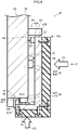
- FIG. 8 and FIG. 9 are drawings showing a fourth embodiment; parts identical or similar to those of the first embodiment to the third embodiment are denoted by the same reference signs and description thereof is omitted, and only parts that are different will be described.
- the tactile sensor 26 provided on the first finger 20 of the robot 10 pertaining to this embodiment differs from those of the first embodiment to the third embodiment in that it has a different limiting structure 34 for limiting inclination of the cover 32 with respect to the base portion 30.
- a cover housing portion 90 that is inwardly set back is formed in the distal end portion of the base portion side face 38 on the second finger 22 side and in the base portion end face 42 on the second finger 22 side.
- the cover 32 is disposed in the cover housing portion 90, and part of the base portion 30 is covered by the cover 32.
- the contact portion 36 is attached to the cover 32.
- An obverse face 36C of a side face portion 36A of the contact portion 36 and the base portion side face 38 are configured to be positioned in the same plane.
- An obverse face 36D of an end face portion 36B of the contact portion 36 and the base portion end face 42 are configured to be positioned in the same plane.
- a side face mounting hole 94 is formed in the central portion of a side portion bottom surface 92 of the cover housing portion 90 that is set back from the base portion side face 38, and the side face detection unit 50 is disposed in the side face mounting hole 94.
- the side face mounting hole 94 is set to a depth where the contact 50B of the side face detection unit 50 disposed therein projects from the side portion bottom surface 92, and the contact 50B of the side face detection unit 50 is adhered to the side face covering portion 40 of the cover 32.
- An end face mounting hole 98 is formed in the central portion of an end portion bottom surface 96 of the cover housing portion 90 that is set back from the base portion end face 42, and the end face detection unit 52 is disposed in the end face mounting hole 98.
- the end face mounting hole 98 is set to a depth where the contact 52B of the end face detection unit 52 disposed therein projects from the end portion bottom surface 96, and the contact 52B of the end face detection unit 52 is adhered to the end face covering portion 44 of the cover 32.
- movement of the side face covering portion 40 toward the base portion 30 is regulated by the side portion bottom surface 92 on the outer peripheral portion of the side face mounting hole 94, so inclination of the side face covering portion 40 exceeding the allowable amount with respect to the side portion bottom surface 92 is limited.
- movement of the end face covering portion 44 toward the base portion 30 is regulated by the end portion bottom surface 96 on the outer peripheral portion of the end face mounting hole 98, so inclination of the end face covering portion 44 exceeding the allowable amount with respect to the end portion bottom surface 96 is limited.
- the limiting structure 34 is configured in the tactile sensor 26 by the side portion bottom surface 92, the end portion bottom surface 96, the depth of the side face mounting hole 94, and the depth of the end face mounting hole 98.
- the configuration of the limiting structure 34 can be simplified compared to a case where the limiting structure 34 is configured by providing stoppers on the base portion 30 or the cover 32.
- the tactile sensor 26 is not limited to this.
- the tactile sensor 26 may also be provided on a wrist portion of the robot 10.
- the tactile sensor 26 may also be provided on both the first finger 20 and the second finger 22.
- the end face detection unit 52 may also be omitted.
- the detection units 50, 52 may also be provided on the cover 32.
- Aspect 1 is a tactile sensor including:
- Aspect 2 is the tactile sensor of aspect 1, wherein the detection unit detects force applied to the cover from relative displacement of the cover with respect to the base portion.
- Aspect 3 is the tactile sensor of aspect 1 or aspect 2, wherein;
- Aspect 4 is the tactile sensor of aspect 3, wherein the limiting structure comprises a stopper that limits movement of the cover in a direction toward the base portion.
- Aspect 5 is the tactile sensor of aspect 4, wherein the stopper limits movement of a peripheral edge portion of the cover formed in an arbitrary shape.
- Aspect 6 is the tactile sensor of aspect 4 or aspect 5, wherein
- Aspect 7 is the tactile sensor of aspect 4 or aspect 5, wherein
- Aspect 8 is the tactile sensor of any of aspect 1 to aspect 7, wherein a contact portion that contacts a target place is replaceably attached to the cover.
- Aspect 9 is a robot hand including:
- Aspect 10 is a robot including:
Landscapes
- Engineering & Computer Science (AREA)
- Robotics (AREA)
- Mechanical Engineering (AREA)
- Human Computer Interaction (AREA)
- Physics & Mathematics (AREA)
- General Physics & Mathematics (AREA)
- Manipulator (AREA)
Abstract
Description
- The present disclosure relates to a tactile sensor, a robot hand, and a robot.
- In
Japanese Patent Application Laid-open No. 2016-205942 - The multiaxial force sensor includes a sensor unit that has plural pressure sensors and a cover that covers the sensor unit. External forces input to the cover are transmitted to the pressure sensors of the sensor unit.
- However, in the conventional multiaxial force sensor, when an external force is input to, for example, an edge portion of the cover, the cover inclines.
- Additionally, when the external force that is input increases, the inclination of the cover also increases. At this time, the cover becomes largely displaced, at the position to which the external force is input, in a direction toward a base portion. Meanwhile, the part of the cover away from the position where the external force is input becomes largely displaced in a direction away from the base portion.
- Here, when a pressure sensor is disposed in the position where the cover is largely displaced in the direction toward the base portion, an unexpected overload is applied to the pressure sensor. Furthermore, when a pressure sensor is disposed in the position where the cover is largely displaced in the direction away from the base and a contact of the pressure sensor is adhered to the cover, the cover and the contact separate from each other. Because of these issues, there are concerns about the durability of the multiaxial force sensor being reduced.
- It is an object of the present disclosure to provide a tactile sensor, a robot hand, and a robot that can inhibit failures regardless of the position where force is applied to a cover.
- A tactile sensor of the present disclosure includes a cover that is provided so as to cover at least part of a base portion, a detection unit that is disposed between the cover and the base portion and detects force applied to the cover, and a limiting structure that limits inclination of the cover with respect to the base portion.
- According to the present disclosure, failures can be inhibited regardless of the position where force is applied to a cover.
-
-
FIG. 1 is a schematic diagram showing a robot equipped with a robot hand pertaining to a first embodiment. -
FIG. 2 is a sectional view showing main parts of the robot hand having a tactile sensor pertaining to the first embodiment. -
FIG. 3 is a partially transparent view showing main parts of the robot hand viewed from the direction of the arrow A inFIG. 2 . -
FIG. 4 is a sectional view showing main parts of the robot hand having a tactile sensor pertaining to a second embodiment. -
FIG. 5 is a partially transparent view showing main parts of the robot hand viewed from the direction of arrow B inFIG. 4 . -
FIG. 6 is a sectional view showing main parts of the robot hand having a tactile sensor pertaining to a third embodiment. -
FIG. 7 is a partially transparent view showing main parts of the robot hand viewed from the direction of arrow C inFIG. 6 . -
FIG. 8 is a sectional view showing main parts of the robot hand having a tactile sensor pertaining to a fourth embodiment. -
FIG. 9 is a partially transparent view showing main parts of the robot hand viewed from the direction of arrow D inFIG. 8 . - A first embodiment will be described below with reference to
FIG. 1 to FIG. 3 . -
FIG. 1 is a diagram showing arobot 10 pertaining to this embodiment. Therobot 10 includes arobot body 12, arobot arm 14 that extends from therobot body 12, and arobot hand 16 that is provided on a distal end of therobot arm 14. - The
robot arm 14 is supported by therobot body 12 via afirst joint 14A, and therobot arm 14 can rotate and bend with respect to therobot body 12. Furthermore, therobot arm 14 includes asecond joint 14B and athird joint 14C and can bend in arbitrary directions at each of thejoints robot hand 16 is supported by therobot arm 14 via afourth joint 14D, and therobot hand 16 can rotate and bend with respect to therobot arm 14. - The
robot hand 16 includes afirst finger 20 and asecond finger 22, which are disposed opposing each other, and can hold anobject 24 between the twofingers first finger 20 is equipped with atactile sensor 26, and thesecond finger 22 configures an opposing member that opposes thefirst finger 20 equipped with thetactile sensor 26. - A
controller 28 is connected to therobot body 12. Therobot body 12 outputs drive signals to actuators of therobot arm 14 and therobot hand 16 based on control signals from thecontroller 28 to drive therobot arm 14 and therobot hand 16. -
FIG. 2 is a sectional view of main parts showing thefirst finger 20, and abase portion 30 configuring thefirst finger 20 applies gripping force according to relative displacement of the twofingers object 24 when it grips theobject 24 together with the second finger 22 (seeFIG. 1 ). Thebase portion 30 is equipped with thetactile sensor 26. - The
tactile sensor 26 includes acover 32, which is provided so as to cover at least part of thebase portion 30, and a detection unit (detailed below), which is disposed between thecover 32 and thebase portion 30 and detects force F1 applied to thecover 32. Furthermore, thetactile sensor 26 includes alimiting structure 34 that limits inclination of thecover 32 with respect to thebase portion 30. Additionally, acontact portion 36 that contacts a target place of theobject 24 is replaceably attached to thecover 32. - The
cover 32 has a sideface covering portion 40 that is disposed along a baseportion side face 38, which is a face of thebase portion 30 positioned on thesecond finger 22 side, and an endface covering portion 44 that extends from the distal end of the sideface covering portion 40 and is disposed along a baseportion end face 42 on the distal end side of thebase portion 30. Thecover 32 is configured by a stainless steel plate as an example. Thecover 32 may also be configured by, for example, an acrylic plate. - The side
face covering portion 40 and the endface covering portion 44 are formed as rectangular plates, which is an arbitrary shape, and thecover 32 is L-shaped in cross section. The shape of the sideface covering portion 40 and the endface covering portion 44 is not limited to a rectangular shape and may also be another shape. - As shown in
FIG. 2 andFIG. 3 , the detection unit includes a sideface detection unit 50 provided between the baseportion side face 38 and the sideface covering portion 40 and an endface detection unit 52 provided between the baseportion end face 42 and the endface covering portion 44. The sideface detection unit 50 is disposed in a place corresponding to the central portion of the sideface covering portion 40 when viewed from thesecond finger 22 side, and the endface detection unit 52 is disposed in a place corresponding to the width direction central portion of the endface covering portion 44. - It will be noted that a plurality of the side
face detection units 50 may be provided between the baseportion side face 38 and the sideface covering portion 40 and that a plurality of the endface detection units 52 may be provided between the baseportion end face 42 and the endface covering portion 44. - The side
face detection unit 50 and the endface detection unit 52 detect applied forces F1, F2 as electrical changes and transmit the detected electrical changes to thecontroller 28 via a harness not shown in the drawings. Examples of electrical changes include a change in capacitance, a change in resistance value, a change in current, a change in inductance, a charge transfer, and a change in resonance frequency. - The two
detection units - The two
detection units rectangular sensor bodies cylindrical contacts sensor bodies detection units - The
sensor body 50A of the sideface detection unit 50 is fixed to the baseportion side face 38, and the distal end of thecontact 50B of the sideface detection unit 50 is adhered to the sideface covering portion 40 of thecover 32. Thesensor body 52A of the endface detection unit 52 is fixed to the baseportion end face 42, and the distal end of thecontact 52B of the endface detection unit 52 is adhered to the endface covering portion 44 of thecover 32. Because of this, thecover 32 is supported by thebase portion 30 via thedetection units face covering portion 40 and the endface covering portion 44 can be integrally displaced with respect to thebase portion 30. - The
contacts detection units sensor bodies contacts contacts detection units cover 32 from the relative displacement of thecover 32 with respect to thebase portion 30. - The limiting
structure 34 is configured by stoppers that limit movement of thecover 32 in a direction toward thebase portion 30. The stoppers are disposed so as to surround the sideface detection unit 50 and are disposed in the four corners of the sideface covering portion 40. Because of this, the stoppers limit movement of the peripheral edge portion of thecover 32, and the stoppers share and receive, with the sideface detection unit 50, the forces F1, F2 before an overload is applied to thetactile sensor 26. - The stoppers include
side face stoppers 54 provided on the baseportion side face 38 and end facestoppers 56 provided on the baseportion end face 42. The side facestoppers 54 are fixed to thebase portion 30, but they may also be fixed to thecover 32. - A distance dimension R1 from end faces 54A of the
side face stoppers 54 to the sideface covering portion 40 is smaller than a projection dimension T1 by which thecontact 50B projects from thesensor body 50A when a rated load is applied to the sideface detection unit 50. A distance dimension R2 from side faces 56A of theend face stoppers 56 to anend face 44B of the endface covering portion 44 is smaller than the projection dimension T1 by which thecontact 50B projects from thesensor body 50A when the rated load is applied to the sideface detection unit 50. - When the force F1 is applied to the
cover 32 and thecontact 50B of the sideface detection unit 50 largely retracts, thecover 32 hits thestoppers stoppers face detection unit 50, the applied force F1. This regulates movement of the sideface covering portion 40 toward the baseportion side face 38 and thus limits retraction exceeding the allowable amount of thecontact 50B of the sideface detection unit 50 and inhibits input of an overload to the sideface detection unit 50. - As shown in
FIG. 3 , theside face stoppers 54 are disposed in places opposing the two corner portions of the sideface covering portion 40 on therobot arm 14 side, and the rectangular sideface covering portion 40 can hit theside face stoppers 54 at two places on the base end side of thebase portion 30. Furthermore, as shown inFIG. 2 , theend face stoppers 56 are disposed in places opposing both length direction end portions of theend face 44B of the endface covering portion 44, and the rectangular sideface covering portion 40 can hit theend face stoppers 56 via the endface covering portion 44 at two places on the distal end side of thebase portion 30. - Because of this, movement of the rectangular side
face covering portion 40 toward the base portion side face 38 is regulated by thestoppers face covering portion 40 exceeding the allowable amount with respect to thebase portion 30 is limited. - The
contact portion 36 is configured by a rubber material formed in a tabular shape, and thecontact portion 36 mitigates impact and shock between thefirst finger 20 and theobject 24 when thefirst finger 20 and thesecond finger 22 grip theobject 24. - Recessed
portions 58 are formed in the four corners of thecontact portion 36, and throughholes 60 that penetrate to the reverse face are formed in bottom surfaces of the recessedportions 58. Screw holes 62 are formed in places in the sideface covering portion 40 corresponding to the throughholes 60, and screws 64 inserted into the throughholes 60 in thecontact portion 36 are screwed into the screw holes 62, whereby thecontact portion 36 can be replaceably attached to thecover 32. - Next, the action and effects of this embodiment will be described.
- In the
robot 10 of this embodiment, thefirst finger 20 of therobot hand 16 is provided with thetactile sensor 26. Thetactile sensor 26 includes thecover 32 that covers part of thebase portion 30 configuring thefirst finger 20, thedetection units cover 32 and thebase portion 30 and detect the force F1 applied to thecover 32, and the limitingstructure 34 that limits inclination of thecover 32 with respect to thebase portion 30. - Because of this, even when the large force F1 (gripping force) is applied to part of the
cover 32 when thefirst finger 20 and thesecond finger 22 grip theobject 24, inclination of thecover 32 with respect to thebase portion 30 is limited by the limitingstructure 34. - For this reason, even when either of the
detection units base portion 30 when the cover inclines, application of an unexpected overload to thatdetection unit detection unit - Meanwhile, even when either of the
detection units base portion 30 when the cover inclines, separation of thecontact detection unit cover 32 can be inhibited. - Because of this, a reduction in the durability of the
tactile sensor 26 can be inhibited and thus reduce the rate of occurrence of failures. Consequently, loss caused by a failure can be inhibited regardless of the positions where the forces F1, F2 are applied to thecover 32. - Furthermore, the
detection units cover 32 from the relative displacement of thecover 32 with respect to thebase portion 30. For this reason, a reduction in detection accuracy caused by a failure of thedetection units - Additionally, the
cover 32 has the sideface covering portion 40 that is disposed along the base portion side face 38 of thebase portion 30 and the endface covering portion 44 that extends from the distal end portion of the sideface covering portion 40 and is disposed along the base portion end face 42 of thebase portion 30. Furthermore, thedetection units portion side face 38 and the sideface covering portion 40 and between the baseportion end face 42 and the endface covering portion 44. - Because of this, in addition to the force F1 (gripping force) applied from the side face of the
base portion 30, the force F2 (pressing force) from the distal end side of thebase portion 30 can also be detected. - Furthermore, the limiting
structure 34 is configured by thestoppers cover 32 in a direction toward thebase portion 30. For this reason, it becomes possible to adjust the arrangement of thestoppers cover 32. - Moreover, the
stoppers cover 32 formed in an arbitrary shape. For this reason, thestoppers cover 32 compared to a case where they limit movement of the central portion of thecover 32 formed in an arbitrary shape. - Additionally, the
contact portion 36 that contacts the target place is replaceably attached to thecover 32. For this reason,contact portions 36 suited toobjects 24 to be gripped and the work to be performed by therobot hand 16 can be selected and attached. - Specifically, when gripping a
slippery object 24, for example, acontact portion 36 having a high coefficient of friction can be attached, so that workability resulting from therobot 10 can be improved. - Furthermore, when the
contact portion 36 deteriorates, just thecontact portion 36 can be replaced. Because of this, the maintainability of therobot hand 16 is improved. -
FIG. 4 andFIG. 5 are drawings showing a second embodiment; parts identical or similar to those of the first embodiment are denoted by the same reference signs and description thereof is omitted, and only parts that are different will be described. - The
tactile sensor 26 provided on thefirst finger 20 of the robot pertaining to this embodiment differs from that of the first embodiment in that it has a different limitingstructure 34 for limiting inclination of thecover 32 with respect to thebase portion 30. Specifically, the shape of the stoppers configuring the limitingstructure 34 and the shape of thecontact portion 36 are different compared to those of the first embodiment. - That is, the limiting
structure 34 is configured byside face stoppers 54 and end facestoppers 56 that limit movement of thecover 32 in a direction toward thebase portion 30. - The side face
stoppers 54 have sidewardface contacting portions 70 that contact areverse face 40A of the sideface covering portion 40 and limit movement of the sideface covering portion 40 in a direction toward the baseportion side face 38. Furthermore, theside face stoppers 54 have sidewardend contacting portions 72 that contact anend face 40B of the sideface covering portion 40 and limit movement of the endface covering portion 44 in a direction toward the baseportion end face 42. - The side face
stoppers 54 are formed so as to be L-shaped in cross section, and the sidewardface contacting portions 70 are configured by flat surfaces that oppose thereverse face 40A of the sideface covering portion 40. Furthermore, the sidewardend contacting portions 72 are configured by flat surfaces that oppose theend face 40B of the sideface covering portion 40. - The
end face stoppers 56 haveendwardface contacting portions 74 that contact areverse face 44A of the endface covering portion 44 and limit movement of the endface covering portion 44 in a direction toward the baseportion end face 42. Furthermore, theend face stoppers 56 have endwardend contacting portions 76 that contact anend face 44B of the endface covering portion 44 and limit movement of the sideface covering portion 40 in a direction toward the baseportion side face 38. - The
end face stoppers 56 are formed so as to be L-shaped in cross section, and the endwardface contacting portions 74 are configured by flat surfaces that oppose thereverse face 44A of the endface covering portion 44. Furthermore, the endwardend contacting portions 76 are configured by flat surfaces that oppose theend face 44B of the endface covering portion 40. - A distance dimension R3 from the sideward
face contacting portions 70 of theside face stoppers 54 to the sideface covering portion 40 is smaller than the projection dimension T1 by which thecontact 50B projects from thesensor body 50A when the rated load is applied to the sideface detection unit 50. A distance dimension R4 from the endwardend contacting portions 76 of theend face stoppers 56 to theend face 44B of the endface covering portion 44 is smaller than the projection dimension T1 by which thecontact 50B projects from thesensor body 50A when the rated load is applied to the sideface detection unit 50. - A distance dimension R5 from the endward
face contacting portions 74 of theend face stoppers 56 to the endface covering portion 44 is smaller than a projection dimension T2 by which thecontact 52B projects from thesensor body 52A when the rated load is applied to the endface detection unit 52. A distance dimension R6 from the sidewardend contacting portions 72 of theside face stoppers 54 to theend face 40B of the sideface covering portion 40 is smaller than the projection dimension T2 by which thecontact 52B projects from thesensor body 52A when the rated load is applied to the endface detection unit 52. - When the force F1 is applied from the side face side of the
cover 32 and thecontact 50B of the sideface detection unit 50 largely retracts, thecover 32 hits the sidewardface contacting portions 70 of theside face stoppers 54 and the endwardend contacting portions 76 of theend face stoppers 56. When this happens, thestoppers face covering portion 40 toward the baseportion side face 38 and thus limits retraction exceeding the allowable amount of thecontact 50B of the sideface detection unit 50 and inhibits input of an overload to the sideface detection unit 50. - Furthermore, when the force F2 is applied from the distal end side of the
cover 32 and thecontact 52B of the endface detection unit 52 largely retracts, thecover 32 hits the sidewardend contacting portions 72 of theside face stoppers 54 and the endwardface contacting portions 74 of theend face stoppers 56. When this happens, thestoppers face covering portion 44 toward the baseportion end face 42 and thus limits retraction exceeding the allowable amount of thecontact 52B of the endface detection unit 52 and inhibits input of an overload to the endface detection unit 52. - Additionally, movement of the rectangular side
face covering portion 40 toward the base portion side face 38 is regulated by thestoppers face covering portion 40 exceeding the allowable amount with respect to the base portion side face 38 is limited. Furthermore, movement of the rectangular endface covering portion 44 toward the baseportion end face 42 is regulated by thestoppers face covering portion 44 exceeding the allowable amount with respect to the baseportion end face 42 is limited. - The
contact portion 36 has aside face portion 36A disposed along the sideface covering portion 40 of thecover 32 and anend face portion 36B disposed along the endface covering portion 44, and thecontact portion 36 is formed so as to be L-shaped in cross section. - Recessed
portions 58 are formed in the four corners of the side face portion 34A and theend face portion 36B of thecontact portion 36, and screws 64 inserted into throughholes 60 in the bottom surfaces of the recessedportions 58 are screwed into screw holes 62 in thecover 32, whereby thecontact portion 36 can be replaceably attached to thecover 32. - In this embodiment also, the same action and effects can be obtained in regard to parts identical or similar to those of the first embodiment.
- Furthermore, in this embodiment, the force F2 applied to the
cover 32 from the distal end side of thebase portion 30 can be received at the four corners of the endface covering portion 44 by thestoppers face covering portion 44 of thecover 32 with respect to the base portion end face 42 can be limited. - For this reason, application of an unexpected overload to the end
face detection unit 52 can be inhibited, and a failure of the endface detection unit 52 can be inhibited. Furthermore, separation of thecontact 52B of the endface detection unit 52 from thecover 32 can be inhibited. - Because of this, a reduction in the durability of the
tactile sensor 26 can be inhibited and thus reduce the rate of occurrence of failures, and loss caused by a failure can be inhibited regardless of the positions where the forces F1, F2 are applied to thecover 32. - Moreover, in this embodiment, the
end face stoppers 56 having the endwardface contacting portions 74 and the endwardend contacting portions 76 and theside face stoppers 54 having the sidewardend contacting portions 72 and the sidewardface contacting portions 70 are used. Because of this, inclination of the endface covering portion 44 of thecover 32 with respect to the baseportion end face 42 and inclination of the sideface covering portion 40 of thecover 32 with respect to the base portion side face 38 can be limited. -
FIG. 6 andFIG. 7 are drawings showing a third embodiment; parts identical or similar to those of the first embodiment and the second embodiment are denoted by the same reference signs and description thereof is omitted, and only parts that are different will be described. - The
tactile sensor 26 provided on thefirst finger 20 of therobot 10 pertaining to this embodiment differs from those of the first embodiment and the second embodiment in that it has a different limitingstructure 34 for limiting inclination of thecover 32 with respect to thebase portion 30. Specifically, the stoppers configuring the limitingstructure 34 are different compared to those of the first embodiment and the second embodiment. - That is, the stoppers configuring the limiting
structure 34 include firstside face stoppers 80 provided on the baseportion side face 38 and secondside face stoppers 82 provided on the sideface covering portion 40. Furthermore, the stoppers configuring the limitingstructure 34 include firstend face stoppers 84 provided on the baseportion end face 42 and secondend face stoppers 86 provided on the endface covering portion 44. - The second
side face stoppers 82 and the firstend face stoppers 84 limit movement of the sideface covering portion 40 in a direction toward the baseportion side face 38. The firstside face stoppers 80 and the secondend face stoppers 86 limit movement of the endface covering portion 44 in a direction toward the baseportion end face 42. - A distance dimension R7 from the second
side face stoppers 82 to the baseportion side face 38 and a distance dimension R8 from side faces 84A of the firstend face stoppers 84 to theend face 44B of the endface covering portion 44 are smaller than the projection dimension T1 by which thecontact 50B projects when the rated load is applied to the sideface detection unit 50. A distance dimension R9 from side faces 80A of the firstside face stoppers 80 to theend face 40B of the sideface covering portion 40 and a distance dimension R10 from the secondend face stoppers 86 to the base portion end face 42 are smaller than the projection dimension T2 by which thecontact 52B projects when the rated load is applied to the endface detection unit 52. - When the force F1 is applied from the side face side of the
cover 32 and thecontact 50B of the sideface detection unit 50 largely retracts, the secondside face stoppers 82 hit the baseportion side face 38. Furthermore, theend face 44B of the endface covering portion 44 hits the side faces 84A of the firstend face stoppers 84. When this happens, thestoppers face covering portion 40 toward the baseportion side face 38 and thus limits retraction exceeding the allowable amount of thecontact 50B of the sideface detection unit 50 and inhibits input of an overload to the sideface detection unit 50. - Furthermore, when the force F2 is applied from the distal end side of the
cover 32 and thecontact 52B of the endface detection unit 52 largely retracts, theend face 40B of the sideface covering portion 40 hits the side faces 80A of the firstside face stoppers 80. Furthermore, the secondend face stoppers 86 hit the baseportion end face 42. When this happens, thestoppers face covering portion 44 toward the baseportion end face 42 and thus limits retraction exceeding the allowable amount of thecontact 52B of the endface detection unit 52 and inhibits input of an overload to the endface detection unit 52. - Additionally, movement of the rectangular side
face covering portion 40 toward the base portion side face 38 is regulated at the four corners by thestoppers face covering portion 40 exceeding the allowable amount with respect to the base portion side face 38 is limited. Furthermore, movement of the rectangular endface covering portion 44 toward the baseportion end face 42 is regulated at the four corners by thestoppers face covering portion 44 exceeding the allowable amount with respect to the baseportion end face 42 is limited. - In this embodiment also, the same action and effects can be obtained in regard to parts identical or similar to those of the first embodiment and the second embodiment.
-
FIG. 8 andFIG. 9 are drawings showing a fourth embodiment; parts identical or similar to those of the first embodiment to the third embodiment are denoted by the same reference signs and description thereof is omitted, and only parts that are different will be described. - The
tactile sensor 26 provided on thefirst finger 20 of therobot 10 pertaining to this embodiment differs from those of the first embodiment to the third embodiment in that it has a different limitingstructure 34 for limiting inclination of thecover 32 with respect to thebase portion 30. - In the
base portion 30 configuring thefirst finger 20 of therobot hand 16, a cover housing portion 90 that is inwardly set back is formed in the distal end portion of the base portion side face 38 on thesecond finger 22 side and in the base portion end face 42 on thesecond finger 22 side. Thecover 32 is disposed in the cover housing portion 90, and part of thebase portion 30 is covered by thecover 32. - The
contact portion 36 is attached to thecover 32. Anobverse face 36C of aside face portion 36A of thecontact portion 36 and the base portion side face 38 are configured to be positioned in the same plane. Anobverse face 36D of anend face portion 36B of thecontact portion 36 and the base portion end face 42 are configured to be positioned in the same plane. - A side
face mounting hole 94 is formed in the central portion of a sideportion bottom surface 92 of the cover housing portion 90 that is set back from the baseportion side face 38, and the sideface detection unit 50 is disposed in the sideface mounting hole 94. The side face mountinghole 94 is set to a depth where thecontact 50B of the sideface detection unit 50 disposed therein projects from the sideportion bottom surface 92, and thecontact 50B of the sideface detection unit 50 is adhered to the sideface covering portion 40 of thecover 32. - An end face mounting
hole 98 is formed in the central portion of an endportion bottom surface 96 of the cover housing portion 90 that is set back from the baseportion end face 42, and the endface detection unit 52 is disposed in the endface mounting hole 98. The end face mountinghole 98 is set to a depth where thecontact 52B of the endface detection unit 52 disposed therein projects from the endportion bottom surface 96, and thecontact 52B of the endface detection unit 52 is adhered to the endface covering portion 44 of thecover 32. - When the force F1 is applied from the side face side of the
cover 32 and thecontact 50B of the sideface detection unit 50 largely retracts, thereverse face 40A of the sideface covering portion 40 hits the sideportion bottom surface 92. When this happens, the sideportion bottom surface 92 receives the applied force F1. This regulates movement of the sideface covering portion 40 and thus limits retraction exceeding the allowable amount of thecontact 50B of the sideface detection unit 50 and inhibits input of an overload to the sideface detection unit 50. - Furthermore, when the force F2 is applied from the distal end side of the
cover 32 and thecontact 52B of the endface detection unit 52 largely retracts, thereverse face 44A of the endface covering portion 44 hits the endportion bottom surface 96. When this happens, the endportion bottom surface 96 receives the applied force F2. This regulates movement of the endface covering portion 44 and thus limits retraction exceeding the allowable amount of thecontact 52B of the endface detection unit 52 and inhibits input of an overload to the endface detection unit 52. - Additionally, movement of the side
face covering portion 40 toward thebase portion 30 is regulated by the sideportion bottom surface 92 on the outer peripheral portion of the sideface mounting hole 94, so inclination of the sideface covering portion 40 exceeding the allowable amount with respect to the sideportion bottom surface 92 is limited. Furthermore, movement of the endface covering portion 44 toward thebase portion 30 is regulated by the endportion bottom surface 96 on the outer peripheral portion of the endface mounting hole 98, so inclination of the endface covering portion 44 exceeding the allowable amount with respect to the endportion bottom surface 96 is limited. - The limiting
structure 34 is configured in thetactile sensor 26 by the sideportion bottom surface 92, the endportion bottom surface 96, the depth of the sideface mounting hole 94, and the depth of the endface mounting hole 98. - In this embodiment also, the same action and effects can be obtained in regard to parts identical or similar to those of the first embodiment to the third embodiment.
- Furthermore, the configuration of the limiting
structure 34 can be simplified compared to a case where the limitingstructure 34 is configured by providing stoppers on thebase portion 30 or thecover 32. - It will be noted that although in the embodiments a case was described where the
tactile sensor 26 is provided on thefirst finger 20 of therobot hand 16, thetactile sensor 26 is not limited to this. For example, thetactile sensor 26 may also be provided on a wrist portion of therobot 10. Furthermore, thetactile sensor 26 may also be provided on both thefirst finger 20 and thesecond finger 22. Moreover, the endface detection unit 52 may also be omitted. Furthermore, thedetection units cover 32. - Below is a description of the reference signs.
- 10
- Robot
- 12
- Robot Body
- 16
- Robot Hand
- 20
- First Finger
- 22
- Second Finger
- 24
- Object
- 26
- Tactile Sensor
- 30
- Base Portion
- 32
- Cover
- 34
- Limiting Structure
- 36
- Contact Portion
- 38
- Base Portion Side Face
- 40
- Side Face Covering Portion
- 42
- Base Portion End Face
- 44
- End Face Covering Portion
- 50
- Side Face Detection Unit
- 52
- End Face Detection Unit
- 54
- Side Face Stopper
- 56
- End Face Stopper
- 70
- Sideward Face Contacting Portion
- 72
- Sideward End Contacting Portion
- 74
- Endward Face Contacting Portion
- 76
- Endward End Contacting Portion
- 80
- First Side Face Stopper
- 82
- Second Side Face Stopper
- 84
- First End Face Stopper
- 86
- Second End Face Stopper
- From this specification the following aspects are conceptualized.
- Aspect 1 is a tactile sensor including:
- a cover that is provided so as to cover at least part of a base portion;
- a detection unit that is disposed between the cover and the base portion and detects force applied to the cover; and
- a limiting structure that limits inclination of the cover with respect to the base portion.
- Aspect 2 is the tactile sensor of aspect 1, wherein the detection unit detects force applied to the cover from relative displacement of the cover with respect to the base portion.
- Aspect 3 is the tactile sensor of aspect 1 or aspect 2, wherein;
- the cover has a side face covering portion that is disposed along a base portion side face of the base portion and an end face covering portion that extends from the side face covering portion and is disposed along a base portion end face of the base portion, and
- the detection unit is disposed between the base portion side face and the side face covering portion and between the base portion end face and the end face covering portion.
-
Aspect 4 is the tactile sensor of aspect 3, wherein the limiting structure comprises a stopper that limits movement of the cover in a direction toward the base portion. - Aspect 5 is the tactile sensor of
aspect 4, wherein the stopper limits movement of a peripheral edge portion of the cover formed in an arbitrary shape. - Aspect 6 is the tactile sensor of
aspect 4 or aspect 5, wherein - the stopper includes a side face stopper provided at the base portion side face and an end face stopper provided at the base portion end face,
- the side face stopper has a sideward face contacting portion that contacts the side face covering portion and limits movement of the side face covering portion in a direction toward the base portion side face and a sideward end contacting portion that contacts an end face of the side face covering portion and limits movement of the end face covering portion in a direction toward the base portion end face, and
- the end face stopper has an endward face contacting portion that contacts the end face covering portion and limits movement of the end face covering portion in a direction toward the base portion end face and an endward end contacting portion that contacts an end face of the end face covering portion and limits movement of the side face covering portion in a direction toward the base portion side face.
- Aspect 7 is the tactile sensor of
aspect 4 or aspect 5, wherein - the stopper includes a first side face stopper provided at the base portion side face, a second side face stopper provided at the side face covering portion, a first end face stopper provided at the base portion end face, and a second end face stopper provided at the end face covering portion, and
- the second side face stopper and the first end face stopper limit movement of the side face covering portion in a direction toward the base portion side face, and the first side face stopper and the second end face stopper limit movement of the end face covering portion in a direction toward the base portion end face.
- Aspect 8 is the tactile sensor of any of aspect 1 to aspect 7, wherein a contact portion that contacts a target place is replaceably attached to the cover.
- Aspect 9 is a robot hand including:
- the tactile sensor of any of aspect 1 to aspect 8; and
- an opposing member that is disposed opposing the tactile sensor and grips an object between itself and the tactile sensor.
-
Aspect 10 is a robot including: - the robot hand of aspect 9; and
- a robot body that drives the robot hand.
- All publications, patent applications, and technical standards mentioned in this specification are incorporated by reference herein to the same extent as if each individual publication, patent application, or technical standard were specifically and individually indicated to be incorporated by reference.
Claims (10)
- A tactile sensor comprising:a cover that is provided so as to cover at least part of a base portion;a detection unit that is disposed between the cover and the base portion and detects force applied to the cover; anda limiting structure that limits inclination of the cover with respect to the base portion.
- The tactile sensor of claim 1, wherein the detection unit detects force applied to the cover from relative displacement of the cover with respect to the base portion.
- The tactile sensor of claim 1 or claim 2, wherein:the cover has a side face covering portion that is disposed along a base portion side face of the base portion and an end face covering portion that extends from the side face covering portion and is disposed along a base portion end face of the base portion, andthe detection unit is disposed between the base portion side face and the side face covering portion and between the base portion end face and the end face covering portion.
- The tactile sensor of claim 3, wherein the limiting structure comprises a stopper that limits movement of the cover in a direction toward the base portion.
- The tactile sensor of claim 4, wherein the stopper limits movement of a peripheral edge portion of the cover formed in an arbitrary shape.
- The tactile sensor of claim 4 or claim 5, wherein:the stopper includes a side face stopper provided at the base portion side face and an end face stopper provided at the base portion end face,the side face stopper has a sideward face contacting portion that contacts the side face covering portion and limits movement of the side face covering portion in a direction toward the base portion side face and a sideward end contacting portion that contacts an end face of the side face covering portion and limits movement of the end face covering portion in a direction toward the base portion end face, andthe end face stopper has an endward face contacting portion that contacts the end face covering portion and limits movement of the end face covering portion in a direction toward the base portion end face and an endward end contacting portion that contacts an end face of the end face covering portion and limits movement of the side face covering portion in a direction toward the base portion side face.
- The tactile sensor of claim 4 or claim 5, wherein:the stopper includes a first side face stopper provided at the base portion side face, a second side face stopper provided at the side face covering portion, a first end face stopper provided at the base portion end face, and a second end face stopper provided at the end face covering portion, andthe second side face stopper and the first end face stopper limit movement of the side face covering portion in a direction toward the base portion side face, and the first side face stopper and the second end face stopper limit movement of the end face covering portion in a direction toward the base portion end face.
- The tactile sensor of any one of claim 1 to claim 7, wherein a contact portion that contacts a target place is replaceably attached to the cover.
- A robot hand comprising:the tactile sensor of any one of claim 1 to claim 8; andan opposing member that is disposed opposing the tactile sensor and grips an object between itself and the tactile sensor.
- A robot comprising:the robot hand of claim 9; anda robot body that drives the robot hand.
Applications Claiming Priority (1)
| Application Number | Priority Date | Filing Date | Title |
|---|---|---|---|
| PCT/JP2019/022639 WO2020246008A1 (en) | 2019-06-06 | 2019-06-06 | Tactile sensor, robot hand, and robot |
Publications (2)
| Publication Number | Publication Date |
|---|---|
| EP3981561A1 true EP3981561A1 (en) | 2022-04-13 |
| EP3981561A4 EP3981561A4 (en) | 2023-01-11 |
Family
ID=73653051
Family Applications (1)
| Application Number | Title | Priority Date | Filing Date |
|---|---|---|---|
| EP19932180.3A Withdrawn EP3981561A4 (en) | 2019-06-06 | 2019-06-06 | TOUCH SENSOR, ROBOT HAND AND ROBOT |
Country Status (5)
| Country | Link |
|---|---|
| US (1) | US12109683B2 (en) |
| EP (1) | EP3981561A4 (en) |
| JP (1) | JP7306453B2 (en) |
| CN (1) | CN113874179A (en) |
| WO (1) | WO2020246008A1 (en) |
Families Citing this family (3)
| Publication number | Priority date | Publication date | Assignee | Title |
|---|---|---|---|---|
| US12600031B2 (en) | 2023-10-20 | 2026-04-14 | Tacta Systems Inc. | Tactile robotic training platform |
| US20260028224A1 (en) | 2024-07-29 | 2026-01-29 | Tacta Systems Inc. | Embedded Digital Sensor Structure |
| US12602110B2 (en) | 2024-08-09 | 2026-04-14 | Tacta Systems Inc. | Sensing gloves for performing tasks |
Family Cites Families (17)
| Publication number | Priority date | Publication date | Assignee | Title |
|---|---|---|---|---|
| JPS537071A (en) * | 1976-07-09 | 1978-01-23 | Hitachi Ltd | Finger mechanism of robot |
| JPH0579443U (en) * | 1992-03-27 | 1993-10-29 | 株式会社松下製作所 | Overload prevention device in load cell |
| JP2002365122A (en) * | 2001-06-06 | 2002-12-18 | Eiji Hayashi | Weighing device, automatic cooker provided with the same, and robot hand |
| JP4701549B2 (en) * | 2001-07-04 | 2011-06-15 | 株式会社島津製作所 | Balance overload prevention device |
| JP2005098949A (en) * | 2003-09-05 | 2005-04-14 | A & D Co Ltd | Load cell unit |
| FR2917660B1 (en) * | 2007-06-25 | 2009-09-25 | Commissariat Energie Atomique | CLAMP FOR MANIPULATOR ROBOT WITH IMPROVED CLAMPING PRECISION AND MANIPULATOR ROBOT COMPRISING AT LEAST ONE SUCH CLAMP. |
| JP5387412B2 (en) | 2007-11-21 | 2014-01-15 | 株式会社安川電機 | Transport robot, housing, semiconductor manufacturing equipment and sorter equipment |
| DE102008005901B4 (en) * | 2008-01-24 | 2018-08-09 | Deutsches Zentrum für Luft- und Raumfahrt e.V. | Sterile barrier for a surgical robot with torque sensors |
| KR101479232B1 (en) * | 2008-05-13 | 2015-01-06 | 삼성전자 주식회사 | Robot, robot hand, control method of robot hand |
| JP5410373B2 (en) * | 2010-07-02 | 2014-02-05 | 日立建機株式会社 | Double-armed work machine |
| JP5760485B2 (en) * | 2011-02-17 | 2015-08-12 | セイコーエプソン株式会社 | Robot hand and robot apparatus |
| JP2016205942A (en) | 2015-04-20 | 2016-12-08 | 学校法人早稲田大学 | Multi-axis force sensor |
| DE102015214170A1 (en) * | 2015-07-27 | 2017-02-02 | Kuka Roboter Gmbh | Robot with a force measuring device |
| JP2017187362A (en) * | 2016-04-05 | 2017-10-12 | 株式会社フジクラ | Load detection sensor and sheet device |
| CN206114162U (en) * | 2016-08-26 | 2017-04-19 | 台衡精密测控(昆山)股份有限公司 | Pressure sensor overload protection device |
| CN110799313A (en) | 2017-06-21 | 2020-02-14 | 斋藤创造研究所株式会社 | Manipulator and robot |
| US20200171677A1 (en) * | 2017-08-10 | 2020-06-04 | Thk Co., Ltd. | Hand mechanism and gripping system |
-
2019
- 2019-06-06 CN CN201980096831.4A patent/CN113874179A/en active Pending
- 2019-06-06 EP EP19932180.3A patent/EP3981561A4/en not_active Withdrawn
- 2019-06-06 JP JP2021524624A patent/JP7306453B2/en active Active
- 2019-06-06 US US17/615,449 patent/US12109683B2/en active Active
- 2019-06-06 WO PCT/JP2019/022639 patent/WO2020246008A1/en not_active Ceased
Also Published As
| Publication number | Publication date |
|---|---|
| US12109683B2 (en) | 2024-10-08 |
| CN113874179A (en) | 2021-12-31 |
| JP7306453B2 (en) | 2023-07-11 |
| WO2020246008A1 (en) | 2020-12-10 |
| US20220227006A1 (en) | 2022-07-21 |
| JPWO2020246008A1 (en) | 2020-12-10 |
| EP3981561A4 (en) | 2023-01-11 |
Similar Documents
| Publication | Publication Date | Title |
|---|---|---|
| US10583570B2 (en) | Displacement measurement device, robot, and robot arm | |
| EP3981561A1 (en) | Tactile sensor, robot hand, and robot | |
| US10578500B2 (en) | Force detecting device and robot | |
| US9267779B2 (en) | Flexible mount for coupling force actuator to caliper jaw | |
| US11788905B2 (en) | Capacitance sensor | |
| US20150266184A1 (en) | Force detection device and robot | |
| US10677667B2 (en) | Component transducer and multi-component transducer using such component transducer as well as use of such multi-component transducer | |
| WO2020246007A1 (en) | Tactile sensor, robot hand, and robot | |
| US8904884B2 (en) | Torque sensor | |
| KR101261137B1 (en) | Slip sensor using flexible dielectric material | |
| US11906372B2 (en) | Capacitance sensor and measurement device | |
| US11740150B2 (en) | Electrostatic capacity sensor | |
| CN115533948A (en) | Piezoelectric sensor and gripper | |
| JP7830846B2 (en) | Piezoelectric sensor and hand | |
| US11320326B2 (en) | Force sensor and sensing element thereof | |
| US20220227011A1 (en) | Tactile Sensor, Robot Hand, and Robot | |
| Wolffenbuttel et al. | Compliant capacitive wrist sensor for use in industrial robots | |
| US10983015B2 (en) | Force detecting device and robot | |
| KR101552801B1 (en) | Tactile sensor | |
| JP7381091B2 (en) | Tactile sensor device and robot hand device using the same | |
| WO2023105643A1 (en) | Displacement detection device |
Legal Events
| Date | Code | Title | Description |
|---|---|---|---|
| STAA | Information on the status of an ep patent application or granted ep patent |
Free format text: STATUS: THE INTERNATIONAL PUBLICATION HAS BEEN MADE |
|
| PUAI | Public reference made under article 153(3) epc to a published international application that has entered the european phase |
Free format text: ORIGINAL CODE: 0009012 |
|
| STAA | Information on the status of an ep patent application or granted ep patent |
Free format text: STATUS: REQUEST FOR EXAMINATION WAS MADE |
|
| 17P | Request for examination filed |
Effective date: 20211202 |
|
| AK | Designated contracting states |
Kind code of ref document: A1 Designated state(s): AL AT BE BG CH CY CZ DE DK EE ES FI FR GB GR HR HU IE IS IT LI LT LU LV MC MK MT NL NO PL PT RO RS SE SI SK SM TR |
|
| DAV | Request for validation of the european patent (deleted) | ||
| DAX | Request for extension of the european patent (deleted) | ||
| REG | Reference to a national code |
Ref country code: DE Ref legal event code: R079 Free format text: PREVIOUS MAIN CLASS: B25J0019020000 Ipc: B25J0013080000 |
|
| A4 | Supplementary search report drawn up and despatched |
Effective date: 20221208 |
|
| RIC1 | Information provided on ipc code assigned before grant |
Ipc: B25J 15/08 20060101ALI20221202BHEP Ipc: B25J 19/02 20060101ALI20221202BHEP Ipc: B25J 13/08 20060101AFI20221202BHEP |
|
| STAA | Information on the status of an ep patent application or granted ep patent |
Free format text: STATUS: EXAMINATION IS IN PROGRESS |
|
| 17Q | First examination report despatched |
Effective date: 20240513 |
|
| GRAP | Despatch of communication of intention to grant a patent |
Free format text: ORIGINAL CODE: EPIDOSNIGR1 |
|
| STAA | Information on the status of an ep patent application or granted ep patent |
Free format text: STATUS: GRANT OF PATENT IS INTENDED |
|
| INTG | Intention to grant announced |
Effective date: 20250728 |
|
| STAA | Information on the status of an ep patent application or granted ep patent |
Free format text: STATUS: THE APPLICATION IS DEEMED TO BE WITHDRAWN |
|
| 18D | Application deemed to be withdrawn |
Effective date: 20251129 |