EP3981365A1 - Spinal intrabody osteotomy implant system - Google Patents
Spinal intrabody osteotomy implant system Download PDFInfo
- Publication number
- EP3981365A1 EP3981365A1 EP21204442.4A EP21204442A EP3981365A1 EP 3981365 A1 EP3981365 A1 EP 3981365A1 EP 21204442 A EP21204442 A EP 21204442A EP 3981365 A1 EP3981365 A1 EP 3981365A1
- Authority
- EP
- European Patent Office
- Prior art keywords
- implant
- intrabody
- stabilization system
- anterior
- posterior
- Prior art date
- Legal status (The legal status is an assumption and is not a legal conclusion. Google has not performed a legal analysis and makes no representation as to the accuracy of the status listed.)
- Pending
Links
- 239000007943 implant Substances 0.000 title claims abstract description 112
- 230000001154 acute effect Effects 0.000 claims abstract description 21
- 230000008468 bone growth Effects 0.000 claims description 11
- 230000006641 stabilisation Effects 0.000 claims description 11
- 238000011105 stabilization Methods 0.000 claims description 11
- 230000000295 complement effect Effects 0.000 claims description 2
- 230000002146 bilateral effect Effects 0.000 claims 1
- 238000000034 method Methods 0.000 abstract description 30
- 230000001045 lordotic effect Effects 0.000 abstract description 8
- 238000012937 correction Methods 0.000 description 16
- 239000000463 material Substances 0.000 description 12
- 210000000988 bone and bone Anatomy 0.000 description 10
- -1 polyethylene terephthalate Polymers 0.000 description 8
- 239000004696 Poly ether ether ketone Substances 0.000 description 7
- 210000003484 anatomy Anatomy 0.000 description 7
- 229920002530 polyetherether ketone Polymers 0.000 description 7
- 239000001506 calcium phosphate Substances 0.000 description 6
- 239000000919 ceramic Substances 0.000 description 6
- 239000002131 composite material Substances 0.000 description 6
- QORWJWZARLRLPR-UHFFFAOYSA-H tricalcium bis(phosphate) Chemical compound [Ca+2].[Ca+2].[Ca+2].[O-]P([O-])([O-])=O.[O-]P([O-])([O-])=O QORWJWZARLRLPR-UHFFFAOYSA-H 0.000 description 6
- 208000000875 Spinal Curvatures Diseases 0.000 description 5
- RTAQQCXQSZGOHL-UHFFFAOYSA-N Titanium Chemical compound [Ti] RTAQQCXQSZGOHL-UHFFFAOYSA-N 0.000 description 5
- 238000000576 coating method Methods 0.000 description 5
- 229920001971 elastomer Polymers 0.000 description 5
- 229910052588 hydroxylapatite Inorganic materials 0.000 description 5
- 229910052751 metal Inorganic materials 0.000 description 5
- 239000002184 metal Substances 0.000 description 5
- 150000002739 metals Chemical class 0.000 description 5
- XYJRXVWERLGGKC-UHFFFAOYSA-D pentacalcium;hydroxide;triphosphate Chemical compound [OH-].[Ca+2].[Ca+2].[Ca+2].[Ca+2].[Ca+2].[O-]P([O-])([O-])=O.[O-]P([O-])([O-])=O.[O-]P([O-])([O-])=O XYJRXVWERLGGKC-UHFFFAOYSA-D 0.000 description 5
- 229920000642 polymer Polymers 0.000 description 5
- 229910052719 titanium Inorganic materials 0.000 description 5
- 239000010936 titanium Substances 0.000 description 5
- 108010007726 Bone Morphogenetic Proteins Proteins 0.000 description 4
- 102000007350 Bone Morphogenetic Proteins Human genes 0.000 description 4
- 208000020307 Spinal disease Diseases 0.000 description 4
- 229940112869 bone morphogenetic protein Drugs 0.000 description 4
- OYPRJOBELJOOCE-UHFFFAOYSA-N Calcium Chemical compound [Ca] OYPRJOBELJOOCE-UHFFFAOYSA-N 0.000 description 3
- 229910052791 calcium Inorganic materials 0.000 description 3
- 239000011575 calcium Substances 0.000 description 3
- 229910000389 calcium phosphate Inorganic materials 0.000 description 3
- 235000011010 calcium phosphates Nutrition 0.000 description 3
- 239000005060 rubber Substances 0.000 description 3
- 238000001356 surgical procedure Methods 0.000 description 3
- 210000000115 thoracic cavity Anatomy 0.000 description 3
- 238000011282 treatment Methods 0.000 description 3
- 229910000391 tricalcium phosphate Inorganic materials 0.000 description 3
- 235000019731 tricalcium phosphate Nutrition 0.000 description 3
- 229940078499 tricalcium phosphate Drugs 0.000 description 3
- 208000023178 Musculoskeletal disease Diseases 0.000 description 2
- 229910001069 Ti alloy Inorganic materials 0.000 description 2
- 102000009618 Transforming Growth Factors Human genes 0.000 description 2
- 108010009583 Transforming Growth Factors Proteins 0.000 description 2
- OSGAYBCDTDRGGQ-UHFFFAOYSA-L calcium sulfate Chemical compound [Ca+2].[O-]S([O-])(=O)=O OSGAYBCDTDRGGQ-UHFFFAOYSA-L 0.000 description 2
- 239000011248 coating agent Substances 0.000 description 2
- 230000004069 differentiation Effects 0.000 description 2
- 208000037265 diseases, disorders, signs and symptoms Diseases 0.000 description 2
- 239000000806 elastomer Substances 0.000 description 2
- 238000002513 implantation Methods 0.000 description 2
- 208000014674 injury Diseases 0.000 description 2
- 238000003780 insertion Methods 0.000 description 2
- 230000037431 insertion Effects 0.000 description 2
- 230000001788 irregular Effects 0.000 description 2
- 210000004705 lumbosacral region Anatomy 0.000 description 2
- 238000012986 modification Methods 0.000 description 2
- 230000004048 modification Effects 0.000 description 2
- 238000012856 packing Methods 0.000 description 2
- 229920001652 poly(etherketoneketone) Polymers 0.000 description 2
- 229920006260 polyaryletherketone Polymers 0.000 description 2
- 229920000139 polyethylene terephthalate Polymers 0.000 description 2
- 239000005020 polyethylene terephthalate Substances 0.000 description 2
- 229920002635 polyurethane Polymers 0.000 description 2
- 239000004814 polyurethane Substances 0.000 description 2
- 230000008569 process Effects 0.000 description 2
- 229910001256 stainless steel alloy Inorganic materials 0.000 description 2
- 208000024891 symptom Diseases 0.000 description 2
- 210000002517 zygapophyseal joint Anatomy 0.000 description 2
- 208000010392 Bone Fractures Diseases 0.000 description 1
- 108010049931 Bone Morphogenetic Protein 2 Proteins 0.000 description 1
- 108010049955 Bone Morphogenetic Protein 4 Proteins 0.000 description 1
- 108010049870 Bone Morphogenetic Protein 7 Proteins 0.000 description 1
- 102100024506 Bone morphogenetic protein 2 Human genes 0.000 description 1
- 102100024505 Bone morphogenetic protein 4 Human genes 0.000 description 1
- 102100022544 Bone morphogenetic protein 7 Human genes 0.000 description 1
- BVKZGUZCCUSVTD-UHFFFAOYSA-L Carbonate Chemical compound [O-]C([O-])=O BVKZGUZCCUSVTD-UHFFFAOYSA-L 0.000 description 1
- 229910000684 Cobalt-chrome Inorganic materials 0.000 description 1
- 102000008186 Collagen Human genes 0.000 description 1
- 108010035532 Collagen Proteins 0.000 description 1
- 239000004593 Epoxy Substances 0.000 description 1
- 102000018233 Fibroblast Growth Factor Human genes 0.000 description 1
- 108050007372 Fibroblast Growth Factor Proteins 0.000 description 1
- 206010017076 Fracture Diseases 0.000 description 1
- AEMRFAOFKBGASW-UHFFFAOYSA-N Glycolic acid Polymers OCC(O)=O AEMRFAOFKBGASW-UHFFFAOYSA-N 0.000 description 1
- 101000599951 Homo sapiens Insulin-like growth factor I Proteins 0.000 description 1
- 102100037852 Insulin-like growth factor I Human genes 0.000 description 1
- 208000003618 Intervertebral Disc Displacement Diseases 0.000 description 1
- 206010061246 Intervertebral disc degeneration Diseases 0.000 description 1
- 206010023509 Kyphosis Diseases 0.000 description 1
- 208000007623 Lordosis Diseases 0.000 description 1
- 206010028980 Neoplasm Diseases 0.000 description 1
- 208000028389 Nerve injury Diseases 0.000 description 1
- 208000001132 Osteoporosis Diseases 0.000 description 1
- 206010033372 Pain and discomfort Diseases 0.000 description 1
- 208000031481 Pathologic Constriction Diseases 0.000 description 1
- 102000010780 Platelet-Derived Growth Factor Human genes 0.000 description 1
- 108010038512 Platelet-Derived Growth Factor Proteins 0.000 description 1
- 229920008285 Poly(ether ketone) PEK Polymers 0.000 description 1
- 239000004952 Polyamide Substances 0.000 description 1
- 239000004697 Polyetherimide Substances 0.000 description 1
- 239000004698 Polyethylene Substances 0.000 description 1
- 229920000954 Polyglycolide Polymers 0.000 description 1
- 239000004642 Polyimide Substances 0.000 description 1
- 229920000265 Polyparaphenylene Polymers 0.000 description 1
- 208000007103 Spondylolisthesis Diseases 0.000 description 1
- 102000004887 Transforming Growth Factor beta Human genes 0.000 description 1
- 108090001012 Transforming Growth Factor beta Proteins 0.000 description 1
- 208000027418 Wounds and injury Diseases 0.000 description 1
- 230000002159 abnormal effect Effects 0.000 description 1
- 230000005856 abnormality Effects 0.000 description 1
- 230000032683 aging Effects 0.000 description 1
- 229910045601 alloy Inorganic materials 0.000 description 1
- 239000000956 alloy Substances 0.000 description 1
- TZCXTZWJZNENPQ-UHFFFAOYSA-L barium sulfate Inorganic materials [Ba+2].[O-]S([O-])(=O)=O TZCXTZWJZNENPQ-UHFFFAOYSA-L 0.000 description 1
- 239000005313 bioactive glass Substances 0.000 description 1
- 239000000560 biocompatible material Substances 0.000 description 1
- 230000002051 biphasic effect Effects 0.000 description 1
- 210000002805 bone matrix Anatomy 0.000 description 1
- 229960001714 calcium phosphate Drugs 0.000 description 1
- 230000015556 catabolic process Effects 0.000 description 1
- 239000010952 cobalt-chrome Substances 0.000 description 1
- 229920001436 collagen Polymers 0.000 description 1
- 230000001054 cortical effect Effects 0.000 description 1
- 230000006378 damage Effects 0.000 description 1
- 208000018180 degenerative disc disease Diseases 0.000 description 1
- 230000003412 degenerative effect Effects 0.000 description 1
- 238000013461 design Methods 0.000 description 1
- 201000010099 disease Diseases 0.000 description 1
- 208000035475 disorder Diseases 0.000 description 1
- 239000003814 drug Substances 0.000 description 1
- 229940079593 drug Drugs 0.000 description 1
- 238000005516 engineering process Methods 0.000 description 1
- 239000004744 fabric Substances 0.000 description 1
- 239000000835 fiber Substances 0.000 description 1
- 229940126864 fibroblast growth factor Drugs 0.000 description 1
- 229910052587 fluorapatite Inorganic materials 0.000 description 1
- 229940077441 fluorapatite Drugs 0.000 description 1
- 230000004927 fusion Effects 0.000 description 1
- PCHJSUWPFVWCPO-UHFFFAOYSA-N gold Chemical compound [Au] PCHJSUWPFVWCPO-UHFFFAOYSA-N 0.000 description 1
- 229910052737 gold Inorganic materials 0.000 description 1
- 239000010931 gold Substances 0.000 description 1
- 230000012010 growth Effects 0.000 description 1
- 239000000017 hydrogel Substances 0.000 description 1
- 230000006872 improvement Effects 0.000 description 1
- 208000021600 intervertebral disc degenerative disease Diseases 0.000 description 1
- 238000002684 laminectomy Methods 0.000 description 1
- 230000007774 longterm Effects 0.000 description 1
- 238000012423 maintenance Methods 0.000 description 1
- 229910001092 metal group alloy Inorganic materials 0.000 description 1
- 210000005036 nerve Anatomy 0.000 description 1
- 230000008764 nerve damage Effects 0.000 description 1
- 229910001000 nickel titanium Inorganic materials 0.000 description 1
- HLXZNVUGXRDIFK-UHFFFAOYSA-N nickel titanium Chemical compound [Ti].[Ti].[Ti].[Ti].[Ti].[Ti].[Ti].[Ti].[Ti].[Ti].[Ti].[Ni].[Ni].[Ni].[Ni].[Ni].[Ni].[Ni].[Ni].[Ni].[Ni].[Ni].[Ni].[Ni].[Ni] HLXZNVUGXRDIFK-UHFFFAOYSA-N 0.000 description 1
- 238000012148 non-surgical treatment Methods 0.000 description 1
- 210000000963 osteoblast Anatomy 0.000 description 1
- 239000002245 particle Substances 0.000 description 1
- 230000037361 pathway Effects 0.000 description 1
- VSIIXMUUUJUKCM-UHFFFAOYSA-D pentacalcium;fluoride;triphosphate Chemical compound [F-].[Ca+2].[Ca+2].[Ca+2].[Ca+2].[Ca+2].[O-]P([O-])([O-])=O.[O-]P([O-])([O-])=O.[O-]P([O-])([O-])=O VSIIXMUUUJUKCM-UHFFFAOYSA-D 0.000 description 1
- 239000004033 plastic Substances 0.000 description 1
- 229920003023 plastic Polymers 0.000 description 1
- 229920002647 polyamide Polymers 0.000 description 1
- 229920001601 polyetherimide Polymers 0.000 description 1
- 229920000573 polyethylene Polymers 0.000 description 1
- 229920001721 polyimide Polymers 0.000 description 1
- 239000002861 polymer material Substances 0.000 description 1
- 229920006124 polyolefin elastomer Polymers 0.000 description 1
- 229920001296 polysiloxane Polymers 0.000 description 1
- 108010033949 polytyrosine Proteins 0.000 description 1
- 230000001737 promoting effect Effects 0.000 description 1
- 230000002787 reinforcement Effects 0.000 description 1
- 206010039722 scoliosis Diseases 0.000 description 1
- 230000036262 stenosis Effects 0.000 description 1
- 208000037804 stenosis Diseases 0.000 description 1
- 229920001059 synthetic polymer Polymers 0.000 description 1
- ZRKFYGHZFMAOKI-QMGMOQQFSA-N tgfbeta Chemical compound C([C@H](NC(=O)[C@H](C(C)C)NC(=O)CNC(=O)[C@H](CCC(O)=O)NC(=O)[C@H](CCCNC(N)=N)NC(=O)[C@H](CC(N)=O)NC(=O)[C@H](CC(C)C)NC(=O)[C@H]([C@@H](C)O)NC(=O)[C@H](CCC(O)=O)NC(=O)[C@H]([C@@H](C)O)NC(=O)[C@H](CC(C)C)NC(=O)CNC(=O)[C@H](C)NC(=O)[C@H](CO)NC(=O)[C@H](CCC(N)=O)NC(=O)[C@@H](NC(=O)[C@H](C)NC(=O)[C@H](C)NC(=O)[C@@H](NC(=O)[C@H](CC(C)C)NC(=O)[C@@H](N)CCSC)C(C)C)[C@@H](C)CC)C(=O)N[C@@H]([C@@H](C)O)C(=O)N[C@@H](C(C)C)C(=O)N[C@@H](CC=1C=CC=CC=1)C(=O)N[C@@H](C)C(=O)N1[C@@H](CCC1)C(=O)N[C@@H]([C@@H](C)O)C(=O)N[C@@H](CC(N)=O)C(=O)N[C@@H](CCC(O)=O)C(=O)N[C@@H](C)C(=O)N[C@@H](CC=1C=CC=CC=1)C(=O)N[C@@H](CCCNC(N)=N)C(=O)N[C@@H](C)C(=O)N[C@@H](CC(C)C)C(=O)N1[C@@H](CCC1)C(=O)N1[C@@H](CCC1)C(=O)N[C@@H](CCCNC(N)=N)C(=O)N[C@@H](CCC(O)=O)C(=O)N[C@@H](CCCNC(N)=N)C(=O)N[C@@H](CO)C(=O)N[C@@H](CCCNC(N)=N)C(=O)N[C@@H](CC(C)C)C(=O)N[C@@H](CC(C)C)C(O)=O)C1=CC=C(O)C=C1 ZRKFYGHZFMAOKI-QMGMOQQFSA-N 0.000 description 1
- 229920001169 thermoplastic Polymers 0.000 description 1
- 229920002725 thermoplastic elastomer Polymers 0.000 description 1
- 229920001187 thermosetting polymer Polymers 0.000 description 1
- 239000004416 thermosoftening plastic Substances 0.000 description 1
- 230000008467 tissue growth Effects 0.000 description 1
- 230000009261 transgenic effect Effects 0.000 description 1
- 230000008733 trauma Effects 0.000 description 1
Images


Classifications
-
- A—HUMAN NECESSITIES
- A61—MEDICAL OR VETERINARY SCIENCE; HYGIENE
- A61B—DIAGNOSIS; SURGERY; IDENTIFICATION
- A61B17/00—Surgical instruments, devices or methods, e.g. tourniquets
- A61B17/56—Surgical instruments or methods for treatment of bones or joints; Devices specially adapted therefor
- A61B17/58—Surgical instruments or methods for treatment of bones or joints; Devices specially adapted therefor for osteosynthesis, e.g. bone plates, screws, setting implements or the like
- A61B17/68—Internal fixation devices, including fasteners and spinal fixators, even if a part thereof projects from the skin
- A61B17/70—Spinal positioners or stabilisers ; Bone stabilisers comprising fluid filler in an implant
- A61B17/7074—Tools specially adapted for spinal fixation operations other than for bone removal or filler handling
- A61B17/7076—Tools specially adapted for spinal fixation operations other than for bone removal or filler handling for driving, positioning or assembling spinal clamps or bone anchors specially adapted for spinal fixation
- A61B17/7077—Tools specially adapted for spinal fixation operations other than for bone removal or filler handling for driving, positioning or assembling spinal clamps or bone anchors specially adapted for spinal fixation for moving bone anchors attached to vertebrae, thereby displacing the vertebrae
- A61B17/708—Tools specially adapted for spinal fixation operations other than for bone removal or filler handling for driving, positioning or assembling spinal clamps or bone anchors specially adapted for spinal fixation for moving bone anchors attached to vertebrae, thereby displacing the vertebrae with tubular extensions coaxially mounted on the bone anchors
-
- A—HUMAN NECESSITIES
- A61—MEDICAL OR VETERINARY SCIENCE; HYGIENE
- A61F—FILTERS IMPLANTABLE INTO BLOOD VESSELS; PROSTHESES; DEVICES PROVIDING PATENCY TO, OR PREVENTING COLLAPSING OF, TUBULAR STRUCTURES OF THE BODY, e.g. STENTS; ORTHOPAEDIC, NURSING OR CONTRACEPTIVE DEVICES; FOMENTATION; TREATMENT OR PROTECTION OF EYES OR EARS; BANDAGES, DRESSINGS OR ABSORBENT PADS; FIRST-AID KITS
- A61F2/00—Filters implantable into blood vessels; Prostheses, i.e. artificial substitutes or replacements for parts of the body; Appliances for connecting them with the body; Devices providing patency to, or preventing collapsing of, tubular structures of the body, e.g. stents
- A61F2/02—Prostheses implantable into the body
- A61F2/30—Joints
- A61F2/44—Joints for the spine, e.g. vertebrae, spinal discs
-
- A—HUMAN NECESSITIES
- A61—MEDICAL OR VETERINARY SCIENCE; HYGIENE
- A61B—DIAGNOSIS; SURGERY; IDENTIFICATION
- A61B17/00—Surgical instruments, devices or methods, e.g. tourniquets
- A61B17/56—Surgical instruments or methods for treatment of bones or joints; Devices specially adapted therefor
- A61B17/58—Surgical instruments or methods for treatment of bones or joints; Devices specially adapted therefor for osteosynthesis, e.g. bone plates, screws, setting implements or the like
- A61B17/68—Internal fixation devices, including fasteners and spinal fixators, even if a part thereof projects from the skin
- A61B17/70—Spinal positioners or stabilisers ; Bone stabilisers comprising fluid filler in an implant
- A61B17/7001—Screws or hooks combined with longitudinal elements which do not contact vertebrae
- A61B17/7032—Screws or hooks with U-shaped head or back through which longitudinal rods pass
-
- A—HUMAN NECESSITIES
- A61—MEDICAL OR VETERINARY SCIENCE; HYGIENE
- A61B—DIAGNOSIS; SURGERY; IDENTIFICATION
- A61B17/00—Surgical instruments, devices or methods, e.g. tourniquets
- A61B17/56—Surgical instruments or methods for treatment of bones or joints; Devices specially adapted therefor
- A61B17/58—Surgical instruments or methods for treatment of bones or joints; Devices specially adapted therefor for osteosynthesis, e.g. bone plates, screws, setting implements or the like
- A61B17/68—Internal fixation devices, including fasteners and spinal fixators, even if a part thereof projects from the skin
- A61B17/70—Spinal positioners or stabilisers ; Bone stabilisers comprising fluid filler in an implant
- A61B17/7074—Tools specially adapted for spinal fixation operations other than for bone removal or filler handling
- A61B17/7083—Tools for guidance or insertion of tethers, rod-to-anchor connectors, rod-to-rod connectors, or longitudinal elements
- A61B17/7085—Tools for guidance or insertion of tethers, rod-to-anchor connectors, rod-to-rod connectors, or longitudinal elements for insertion of a longitudinal element down one or more hollow screw or hook extensions, i.e. at least a part of the element within an extension has a component of movement parallel to the extension's axis
-
- A—HUMAN NECESSITIES
- A61—MEDICAL OR VETERINARY SCIENCE; HYGIENE
- A61B—DIAGNOSIS; SURGERY; IDENTIFICATION
- A61B17/00—Surgical instruments, devices or methods, e.g. tourniquets
- A61B17/56—Surgical instruments or methods for treatment of bones or joints; Devices specially adapted therefor
- A61B17/58—Surgical instruments or methods for treatment of bones or joints; Devices specially adapted therefor for osteosynthesis, e.g. bone plates, screws, setting implements or the like
- A61B17/68—Internal fixation devices, including fasteners and spinal fixators, even if a part thereof projects from the skin
- A61B17/80—Cortical plates, i.e. bone plates; Instruments for holding or positioning cortical plates, or for compressing bones attached to cortical plates
- A61B17/8095—Wedge osteotomy devices
-
- A—HUMAN NECESSITIES
- A61—MEDICAL OR VETERINARY SCIENCE; HYGIENE
- A61F—FILTERS IMPLANTABLE INTO BLOOD VESSELS; PROSTHESES; DEVICES PROVIDING PATENCY TO, OR PREVENTING COLLAPSING OF, TUBULAR STRUCTURES OF THE BODY, e.g. STENTS; ORTHOPAEDIC, NURSING OR CONTRACEPTIVE DEVICES; FOMENTATION; TREATMENT OR PROTECTION OF EYES OR EARS; BANDAGES, DRESSINGS OR ABSORBENT PADS; FIRST-AID KITS
- A61F2/00—Filters implantable into blood vessels; Prostheses, i.e. artificial substitutes or replacements for parts of the body; Appliances for connecting them with the body; Devices providing patency to, or preventing collapsing of, tubular structures of the body, e.g. stents
- A61F2/02—Prostheses implantable into the body
- A61F2/30—Joints
- A61F2/30767—Special external or bone-contacting surface, e.g. coating for improving bone ingrowth
-
- A—HUMAN NECESSITIES
- A61—MEDICAL OR VETERINARY SCIENCE; HYGIENE
- A61F—FILTERS IMPLANTABLE INTO BLOOD VESSELS; PROSTHESES; DEVICES PROVIDING PATENCY TO, OR PREVENTING COLLAPSING OF, TUBULAR STRUCTURES OF THE BODY, e.g. STENTS; ORTHOPAEDIC, NURSING OR CONTRACEPTIVE DEVICES; FOMENTATION; TREATMENT OR PROTECTION OF EYES OR EARS; BANDAGES, DRESSINGS OR ABSORBENT PADS; FIRST-AID KITS
- A61F2/00—Filters implantable into blood vessels; Prostheses, i.e. artificial substitutes or replacements for parts of the body; Appliances for connecting them with the body; Devices providing patency to, or preventing collapsing of, tubular structures of the body, e.g. stents
- A61F2/02—Prostheses implantable into the body
- A61F2/30—Joints
- A61F2002/30001—Additional features of subject-matter classified in A61F2/28, A61F2/30 and subgroups thereof
- A61F2002/30316—The prosthesis having different structural features at different locations within the same prosthesis; Connections between prosthetic parts; Special structural features of bone or joint prostheses not otherwise provided for
- A61F2002/30535—Special structural features of bone or joint prostheses not otherwise provided for
- A61F2002/30593—Special structural features of bone or joint prostheses not otherwise provided for hollow
-
- A—HUMAN NECESSITIES
- A61—MEDICAL OR VETERINARY SCIENCE; HYGIENE
- A61F—FILTERS IMPLANTABLE INTO BLOOD VESSELS; PROSTHESES; DEVICES PROVIDING PATENCY TO, OR PREVENTING COLLAPSING OF, TUBULAR STRUCTURES OF THE BODY, e.g. STENTS; ORTHOPAEDIC, NURSING OR CONTRACEPTIVE DEVICES; FOMENTATION; TREATMENT OR PROTECTION OF EYES OR EARS; BANDAGES, DRESSINGS OR ABSORBENT PADS; FIRST-AID KITS
- A61F2/00—Filters implantable into blood vessels; Prostheses, i.e. artificial substitutes or replacements for parts of the body; Appliances for connecting them with the body; Devices providing patency to, or preventing collapsing of, tubular structures of the body, e.g. stents
- A61F2/02—Prostheses implantable into the body
- A61F2/30—Joints
- A61F2/30767—Special external or bone-contacting surface, e.g. coating for improving bone ingrowth
- A61F2002/3093—Special external or bone-contacting surface, e.g. coating for improving bone ingrowth for promoting ingrowth of bone tissue
-
- A—HUMAN NECESSITIES
- A61—MEDICAL OR VETERINARY SCIENCE; HYGIENE
- A61F—FILTERS IMPLANTABLE INTO BLOOD VESSELS; PROSTHESES; DEVICES PROVIDING PATENCY TO, OR PREVENTING COLLAPSING OF, TUBULAR STRUCTURES OF THE BODY, e.g. STENTS; ORTHOPAEDIC, NURSING OR CONTRACEPTIVE DEVICES; FOMENTATION; TREATMENT OR PROTECTION OF EYES OR EARS; BANDAGES, DRESSINGS OR ABSORBENT PADS; FIRST-AID KITS
- A61F2210/00—Particular material properties of prostheses classified in groups A61F2/00 - A61F2/26 or A61F2/82 or A61F9/00 or A61F11/00 or subgroups thereof
- A61F2210/0014—Particular material properties of prostheses classified in groups A61F2/00 - A61F2/26 or A61F2/82 or A61F9/00 or A61F11/00 or subgroups thereof using shape memory or superelastic materials, e.g. nitinol
-
- A—HUMAN NECESSITIES
- A61—MEDICAL OR VETERINARY SCIENCE; HYGIENE
- A61F—FILTERS IMPLANTABLE INTO BLOOD VESSELS; PROSTHESES; DEVICES PROVIDING PATENCY TO, OR PREVENTING COLLAPSING OF, TUBULAR STRUCTURES OF THE BODY, e.g. STENTS; ORTHOPAEDIC, NURSING OR CONTRACEPTIVE DEVICES; FOMENTATION; TREATMENT OR PROTECTION OF EYES OR EARS; BANDAGES, DRESSINGS OR ABSORBENT PADS; FIRST-AID KITS
- A61F2220/00—Fixations or connections for prostheses classified in groups A61F2/00 - A61F2/26 or A61F2/82 or A61F9/00 or A61F11/00 or subgroups thereof
- A61F2220/0008—Fixation appliances for connecting prostheses to the body
- A61F2220/0016—Fixation appliances for connecting prostheses to the body with sharp anchoring protrusions, e.g. barbs, pins, spikes
-
- A—HUMAN NECESSITIES
- A61—MEDICAL OR VETERINARY SCIENCE; HYGIENE
- A61F—FILTERS IMPLANTABLE INTO BLOOD VESSELS; PROSTHESES; DEVICES PROVIDING PATENCY TO, OR PREVENTING COLLAPSING OF, TUBULAR STRUCTURES OF THE BODY, e.g. STENTS; ORTHOPAEDIC, NURSING OR CONTRACEPTIVE DEVICES; FOMENTATION; TREATMENT OR PROTECTION OF EYES OR EARS; BANDAGES, DRESSINGS OR ABSORBENT PADS; FIRST-AID KITS
- A61F2230/00—Geometry of prostheses classified in groups A61F2/00 - A61F2/26 or A61F2/82 or A61F9/00 or A61F11/00 or subgroups thereof
- A61F2230/0002—Two-dimensional shapes, e.g. cross-sections
- A61F2230/0004—Rounded shapes, e.g. with rounded corners
- A61F2230/0015—Kidney-shaped, e.g. bean-shaped
-
- A—HUMAN NECESSITIES
- A61—MEDICAL OR VETERINARY SCIENCE; HYGIENE
- A61F—FILTERS IMPLANTABLE INTO BLOOD VESSELS; PROSTHESES; DEVICES PROVIDING PATENCY TO, OR PREVENTING COLLAPSING OF, TUBULAR STRUCTURES OF THE BODY, e.g. STENTS; ORTHOPAEDIC, NURSING OR CONTRACEPTIVE DEVICES; FOMENTATION; TREATMENT OR PROTECTION OF EYES OR EARS; BANDAGES, DRESSINGS OR ABSORBENT PADS; FIRST-AID KITS
- A61F2310/00—Prostheses classified in A61F2/28 or A61F2/30 - A61F2/44 being constructed from or coated with a particular material
- A61F2310/00005—The prosthesis being constructed from a particular material
- A61F2310/00011—Metals or alloys
- A61F2310/00017—Iron- or Fe-based alloys, e.g. stainless steel
-
- A—HUMAN NECESSITIES
- A61—MEDICAL OR VETERINARY SCIENCE; HYGIENE
- A61F—FILTERS IMPLANTABLE INTO BLOOD VESSELS; PROSTHESES; DEVICES PROVIDING PATENCY TO, OR PREVENTING COLLAPSING OF, TUBULAR STRUCTURES OF THE BODY, e.g. STENTS; ORTHOPAEDIC, NURSING OR CONTRACEPTIVE DEVICES; FOMENTATION; TREATMENT OR PROTECTION OF EYES OR EARS; BANDAGES, DRESSINGS OR ABSORBENT PADS; FIRST-AID KITS
- A61F2310/00—Prostheses classified in A61F2/28 or A61F2/30 - A61F2/44 being constructed from or coated with a particular material
- A61F2310/00005—The prosthesis being constructed from a particular material
- A61F2310/00011—Metals or alloys
- A61F2310/00023—Titanium or titanium-based alloys, e.g. Ti-Ni alloys
-
- A—HUMAN NECESSITIES
- A61—MEDICAL OR VETERINARY SCIENCE; HYGIENE
- A61F—FILTERS IMPLANTABLE INTO BLOOD VESSELS; PROSTHESES; DEVICES PROVIDING PATENCY TO, OR PREVENTING COLLAPSING OF, TUBULAR STRUCTURES OF THE BODY, e.g. STENTS; ORTHOPAEDIC, NURSING OR CONTRACEPTIVE DEVICES; FOMENTATION; TREATMENT OR PROTECTION OF EYES OR EARS; BANDAGES, DRESSINGS OR ABSORBENT PADS; FIRST-AID KITS
- A61F2310/00—Prostheses classified in A61F2/28 or A61F2/30 - A61F2/44 being constructed from or coated with a particular material
- A61F2310/00005—The prosthesis being constructed from a particular material
- A61F2310/00011—Metals or alloys
- A61F2310/00029—Cobalt-based alloys, e.g. Co-Cr alloys or Vitallium
-
- A—HUMAN NECESSITIES
- A61—MEDICAL OR VETERINARY SCIENCE; HYGIENE
- A61F—FILTERS IMPLANTABLE INTO BLOOD VESSELS; PROSTHESES; DEVICES PROVIDING PATENCY TO, OR PREVENTING COLLAPSING OF, TUBULAR STRUCTURES OF THE BODY, e.g. STENTS; ORTHOPAEDIC, NURSING OR CONTRACEPTIVE DEVICES; FOMENTATION; TREATMENT OR PROTECTION OF EYES OR EARS; BANDAGES, DRESSINGS OR ABSORBENT PADS; FIRST-AID KITS
- A61F2310/00—Prostheses classified in A61F2/28 or A61F2/30 - A61F2/44 being constructed from or coated with a particular material
- A61F2310/00005—The prosthesis being constructed from a particular material
- A61F2310/00179—Ceramics or ceramic-like structures
- A61F2310/00293—Ceramics or ceramic-like structures containing a phosphorus-containing compound, e.g. apatite
-
- A—HUMAN NECESSITIES
- A61—MEDICAL OR VETERINARY SCIENCE; HYGIENE
- A61F—FILTERS IMPLANTABLE INTO BLOOD VESSELS; PROSTHESES; DEVICES PROVIDING PATENCY TO, OR PREVENTING COLLAPSING OF, TUBULAR STRUCTURES OF THE BODY, e.g. STENTS; ORTHOPAEDIC, NURSING OR CONTRACEPTIVE DEVICES; FOMENTATION; TREATMENT OR PROTECTION OF EYES OR EARS; BANDAGES, DRESSINGS OR ABSORBENT PADS; FIRST-AID KITS
- A61F2310/00—Prostheses classified in A61F2/28 or A61F2/30 - A61F2/44 being constructed from or coated with a particular material
- A61F2310/00005—The prosthesis being constructed from a particular material
- A61F2310/00329—Glasses, e.g. bioglass
-
- A—HUMAN NECESSITIES
- A61—MEDICAL OR VETERINARY SCIENCE; HYGIENE
- A61F—FILTERS IMPLANTABLE INTO BLOOD VESSELS; PROSTHESES; DEVICES PROVIDING PATENCY TO, OR PREVENTING COLLAPSING OF, TUBULAR STRUCTURES OF THE BODY, e.g. STENTS; ORTHOPAEDIC, NURSING OR CONTRACEPTIVE DEVICES; FOMENTATION; TREATMENT OR PROTECTION OF EYES OR EARS; BANDAGES, DRESSINGS OR ABSORBENT PADS; FIRST-AID KITS
- A61F2310/00—Prostheses classified in A61F2/28 or A61F2/30 - A61F2/44 being constructed from or coated with a particular material
- A61F2310/00005—The prosthesis being constructed from a particular material
- A61F2310/00359—Bone or bony tissue
-
- A—HUMAN NECESSITIES
- A61—MEDICAL OR VETERINARY SCIENCE; HYGIENE
- A61F—FILTERS IMPLANTABLE INTO BLOOD VESSELS; PROSTHESES; DEVICES PROVIDING PATENCY TO, OR PREVENTING COLLAPSING OF, TUBULAR STRUCTURES OF THE BODY, e.g. STENTS; ORTHOPAEDIC, NURSING OR CONTRACEPTIVE DEVICES; FOMENTATION; TREATMENT OR PROTECTION OF EYES OR EARS; BANDAGES, DRESSINGS OR ABSORBENT PADS; FIRST-AID KITS
- A61F2310/00—Prostheses classified in A61F2/28 or A61F2/30 - A61F2/44 being constructed from or coated with a particular material
- A61F2310/00005—The prosthesis being constructed from a particular material
- A61F2310/00365—Proteins; Polypeptides; Degradation products thereof
- A61F2310/00371—Collagen
Definitions
- the present disclosure generally relates to medical devices, systems and methods for the treatment of musculoskeletal disorders, and more particularly, to a wedged intrabody implant and method for fusing portions of a single vertebral body to achieve a desired spinal curvature and/or angulation.
- Spinal disorders such as degenerative disc disease, disc herniation, osteoporosis, spondylolisthesis, stenosis, scoliosis and other curvature abnormalities, kyphosis, tumor, and fracture may result from factors including trauma, disease and degenerative conditions caused by injury and aging. Spinal disorders typically result in symptoms including pain, nerve damage, and partial or complete loss of mobility. For example, after a disc collapse, severe pain and discomfort can occur due to the pressure exerted on nerves and the spinal column.
- Non-surgical treatments such as medication, rehabilitation and exercise can be effective, however, may fail to relieve the symptoms associated with these disorders.
- Surgical treatment of these spinal disorders includes fusion, fixation, discectomy, laminectomy, osteotomy and implantable prosthetics. These treatments may employ spinal implants and, in some cases, the placement of interbody implants via a variety of invasive, partially invasive and/or minimally invasive surgical pathways.
- surgeons may perform a complete and/or partial osteotomy to remove bony structures from the spine in order to reorient the bones of the spine to provide the patient with a desired spinal curvature.
- an intrabody implant and method are disclosed.
- an intrabody implant is provided for placement between separated portions of a previously-unitary bony structure, such as a vertebral body.
- the intrabody implant comprises first and second surfaces for engaging the first and second portions of the separated bony structure.
- the surfaces of the implant may be provided with titanium or other coatings or a plurality of surface features extending outward from the surfaces to engage the bony structure.
- the second implant surface may be disposed opposite the first implant surface at an acute angle relative to the first surface.
- the implant further comprises a wall disposed between the first and second implant surfaces.
- the wall comprises anterior and posterior portions wherein the respective heights of the posterior and anterior portions are unequal to form the acute angle.
- the intrabody implant may define an aperture extending through the implant to allow for bone growth through the implant.
- the posterior height of the implant may be less than the anterior height of the implant such that the acute angle (which may range widely from 0-90 degrees) introduces a lordotic angle between the first and second portions of the bony structure when the intrabody implant is placed therebetween.
- the intrabody implant portions may also be formed of a polymer material such as PEEK, and be formed with a convex posterior portion and a concave anterior portion to better conform to the anatomy of the separated bony structure.
- the implant may also be sized to occupy a substantial width of the bony structure. For example, a width of the implant may, in some embodiments, be greater than 40 mm.
- Such methods may include steps of: removing a wedge-shaped portion of a single vertebral body to form 2 at least partially-separated portions of the vertebral body; providing a wedge-shaped intrabody implant comprising first and second surfaces disposed at an acute angle relative to one another; placing the wedge-shaped intrabody implant between the 2 at least partially-separated portions; and closing the 2 at least partially-separated portions about the implant.
- the method embodiments may result in the orientation of the 2 at least partially-separated portions of the vertebral body at a correction angle relative to one another.
- the method embodiments described herein may provide lordotic and/or kyphotic correction to a spinal column at the level of the single vertebral body or across multiple levels, as part of an osteotomy procedure that may include, but is not limited to, a pedicle subtraction osteotomy (PSO).
- the closing step disclosed herein may comprise securing the 2 at least partially-separated portions of the single vertebral body relative to one another using a rod and pedicle screw construct.
- the method may also comprise packing the intrabody implant with bone-growth promotion material (in a bone growth aperture defined in the intrabody implant, for example).
- an intrabody implant and related methods of use disclosed herein are discussed in terms of medical devices for the treatment of musculoskeletal disorders and more particularly, in terms of an intrabody implant for placement after osteotomy and related methods for treating a vertebral column.
- the disclosed intrabody implant and methods may provide, for example, a means for more accurately introducing a correction angle to a portion of the spinal column by virtue of the intrabody implant, which may enable a surgeon to more precisely predict the closure and/or correction angle despite variations in wedge angle that may be introduced in the "bone-on-bone" closure of known osteotomy procedures.
- the wedge design of the intrabody implant may aid in the maintenance of anterior vertebral body height while allowing for closure (height collapse) on a posterior portion of the same vertebral body in order to introduce a corrective angulation.
- the various embodiments described herein may also be especially useful in maintaining the shape and position of the vertebral body during and after an osteotomy.
- the anterior portion of the vertebral body (VI, V2) may also break during closure of the angle ⁇ . It may be difficult for a surgeon to predict any shifts that may occur once the anterior portion of the vertebral body breaks.
- the intrabody implant 100 (see FIG. 3 , for example) may help restrict any shift in the bony structures VI, V2 remaining after an osteotomy procedure.
- a method for surgically adjusting a curvature of the spine is provided.
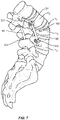
- a vertebral body V is selected for an osteotomy procedure which may include removing portions of the pedicle P, spinous processes SP and/or facet joint structures F at the level of the vertebral body V. While level L3 is depicted in FIG. 1 , a surgeon may apply the procedure described herein to any number of spinal levels in the lumbar, thoracic, or cervical spine to introduce a corrective curvature to the spine.
- the method may further comprise removing a wedge-shaped portion of a single vertebral body V (see FIG 1 ) to form 2 at least partially-separated portions VI, V2 of the single vertebral body V.
- a surgeon may select and/or measure a corrective angle ⁇ to serve as the basis for this step.
- the acute angle ⁇ defined by the surfaces 110, 120 of the implant 100 may be used to ensure that the completed spinal surgery results in a desired level of spinal curvature (see FIG. 3 ) regardless of the angle ⁇ of the removal cut made by the surgeon as part of the removal step.
- the removing step may comprise a pedicle subtraction osteotomy (PSO) procedure wherein the pedicle P, spinous process SP, and/or portions of the facet joint structure F are completely or partially removed from the vertebral body.
- PSO pedicle subtraction osteotomy
- the method may further comprise providing a wedge-shaped intrabody implant 100 (as described further herein with respect to FIGS. 4-6 ) comprising a first surface 110 and a second surface 120, wherein the second surface 120 may be disposed at an acute angle ⁇ to the first surface 110.
- the intrabody implant 100 may be provided with an aperture 101 extending through the wedge-shaped intrabody implant 100 to allow for bone growth therethrough.
- the method may further comprise packing the aperture 101 with a bone-growth promotion material prior to the placing step described herein with respect to FIG. 3 .
- the method further comprises placing the wedge-shaped intrabody implant 100 between the 2 at least partially-separated portions V1, V2 of the single vertebral body V, and closing the 2 at least partially-separated portions V1, V2 of the single vertebral body about the intrabody implant 100. Therefore, the 2 at least partially-separated portions V1, V2 of the single vertebral body are oriented at a correction angle relative to one another.
- the resulting correction angle may be substantially predictable based on the selected implant.
- the correction angle may be within a selected number of degrees of the acute angle defined by the intrabody implant.
- the range of difference between the correction angle and the acute angle may be relatively wide (i.e. 10-90 degrees). In other embodiments, the range of difference between the correction angle and the acute angle may be relatively narrow (i.e. 0-10 degrees).
- the correction angle of the spinal column defined at least in part by the acute angle ⁇ of the intrabody implant may provide a lordotic correction to a spinal column at the level of the single vertebral body V.
- the implant direction may be reversed such that the correction angle of the spinal column defined at least in part by the acute angle ⁇ of the intrabody implant may provide a kyphotic correction to a spinal column at the level of the single vertebral body V.
- the various embodiments of the present invention may provide a correction angle across multiple levels (such that the acute angles ⁇ of several intrabody implants 100 may provide a lordotic correction to a spinal column across 2 or more levels).
- the removing, providing, placing and closing steps disclosed herein may be repeated across two or more levels of the human spine to achieve an overall spinal correction across the two or more levels.
- the closing step described herein may further comprise securing the 2 at least partially separated portions VI, V2 of the vertebral body V about the implant 100 using an extradiscal stabilization system (which may include, for example, a rod 300 and pedicle screw 201, 202 construct as shown generally in FIGS. 3 and 7 .
- the pedicle screws 201, 202 may be inserted into the pedicles of adjacent vertebral bodies V3, V4 and connected via rod 300 that may be shaped and/or bent by the surgeon to further reinforce the corrective angle sought as part of the surgical procedure.
- FIG. 1 extradiscal stabilization system
- FIG. 7 shows a perspective view of a bi-lateral screw 201, 202, 203, 204 and rod 300, 301 construct that may also be used to reinforce the corrected spinal curvature using the various methods described here.
- Various screw and rod systems may be used for the reinforcement step, including but not limited to the SOLERA ® and LEGACY ® extradiscal stabilization systems offered by Medtronic ® Spine.
- an intrabody implant 100 is disclosed for placement between at least 2 separated portions VI, V2 of a bony structure such as a vertebral body V.
- the implant 100 may be formed in whole or in part from a variety of biocompatible materials suitable for long-term implantation.
- the implant 100 may be preferably formed of a polymer such as PEEK.
- the components of implant 100 can be fabricated from a variety of biologically acceptable materials suitable for medical applications, including metals, synthetic polymers, ceramics and bone material and/or their composites, depending on the particular application and/or preference of a medical practitioner.
- the components of implant 100 individually or collectively, can be fabricated from materials such as stainless steel alloys, commercially pure titanium, titanium alloys, Grade 5 titanium, super-elastic titanium alloys, cobalt-chrome alloys, stainless steel alloys, superelastic metallic alloys (e.g., Nitinol, super elasto-plastic metals, such as GUM METALS manufactured by Toyota Material Incorporated of Japan), ceramics and composites thereof such as calcium phosphate (e.g., SKELITE TM manufactured by Biologix Inc.), thermoplastics such as polyaryletherketone (PAEK) including polyetheretherketone (PEEK), polyetherketoneketone (PEKK) and polyetherketone (PEK), carbon-PEEK composites, PEE
- the implant 100 may comprise a first surface 110 configured for engaging a first V1 of the at least two separated portions of the bony structure.
- the implant 100 further comprises a second surface 120, disposed opposite the first surface 110, and configured for engaging a second V2 of the at least two separated portions of the bony structure.
- the first and second surfaces 110, 120 may be disposed at an acute angle ⁇ relative to one another.
- the angle ⁇ may range widely from zero to 90 degrees. However, in some preferable embodiments the angle ⁇ may range from 10 to 30 degrees. In other more preferable embodiments, the angle ⁇ may range from 15 to 25 degrees.
- the implant 100 may further comprise a wall 150 disposed between the first and second surfaces 110, 120.
- the wall 150 comprises an anterior portion 130 and a posterior portion 140.
- the posterior portion 140 has a posterior height and the anterior portion 130 has an anterior height, wherein the posterior and anterior heights are unequal to form the preferably acute angle ⁇ between the first surface 110 and the second surface 120 of the implant 100.
- the posterior height may be less than the anterior height such that the angle ⁇ of the implant 100 introduces a lordotic angle between the first and second portions VI, V2 of the bony structure V (see FIG. 3 , for example).
- the posterior portion 140 and/or anterior portion 130 of the implant may be provided with a convex profile between the first and second surfaces 110, 120 to aid in the ease of insertion of the implant 100.
- the profile may also, in alternate embodiments, be chamfered and/or provided with edge radii to allow for easier insertion of the implant 100 from either the posterior or anterior directions.
- FIG. 6 shows a top view of an implant 100 according to one embodiment wherein the first and second surfaces 110, 120 define an aperture 101 extending through the implant 100 to allow for bone growth through the implant 100 from the first portion V1 of the bony structure V to the second portion V2 (see FIG. 3 , for example).
- the aperture 101 may also be packed with bone growth promoting material, including but not limited to bone allograft, bone xenograft, bone autograft, bone morphogenetic protein (BMP) and/or combinations thereof.
- the implant 100 may be formed in a shape that conforms to the anatomy of the human spine.
- the posterior portion 140 of the wall 150 may comprise an outer concave surface configured to conform to a posterior anatomy of the bony structure V.
- the anterior portion 130 of the wall 150 may comprise an outer convex surface configured to conform to an anterior anatomy of the bony structure V.
- the implant 100 may include a width W extending substantially parallel to the anterior portion 130 and the posterior portion 140.
- the width W of the implant 100 may be chosen to substantially fill the width of the vertebral body V or other bony structure where the intrabody is intended to be placed after osteotomy.
- the width W may be at least 40 mm.
- the width W may be at least 50 mm (when used, for example, in the lower lumbar region).
- the width W may be tailored for use in smaller vertebral bodies (for example, in smaller patients or in the upper thoracic or cervical spine).
- the width W may be in the range of 15-40 mm (or 25-30 mm in some preferable cervical and thoracic embodiments).
- the depth of the implant 100 may also vary accordingly (wherein the depth is measured perpendicular to the width W from the anterior portion 130 to the posterior portion 140). In some embodiments, the depth may range from 10 mm to 50 mm (and preferably from 15-20 mm in certain embodiments).
- the first surface 110 and second surface 120 of the implant 100 may further comprise a plurality of surface features 112 extending outward from the surfaces 110, 120 to engage a complementary surface of the bony structure V.
- the surface features 112 may include, but are not limited to: ridges, teeth, pyramidal structures, roughened irregular projections and/or combinations thereof.
- the surface features 112 may be optimized in shape and/or directional orientation to resist the expulsion of the implant 100 from between the portions VI, V2 of the bony structure when the patient applies weight forces to the spine during the course of standing or movement.
- the surface features 112 may comprise rows of teeth (see FIG 5 ) having a substantially right-triangular profile wherein the teeth are sloped upwards towards the anterior portion 130 of the wall 150 of the implant 100.
- the implant 100 may further comprise a coating applied to one or more of the surfaces 110, 120 and/or the wall 150 to encourage bone growth onto the implant 100.
- Such coatings may include, but are not limited to: gold, titanium, hydroxyapatite (HA) and/or combinations thereof.
- the coatings may be applied with a roughened texture so as to provide a plurality of irregular projections that may serve as surface features 112 to also resist expulsion of the implant 100 after implantation.
- the implant 100 may have substantially smooth surfaces 110, 120 and wall 150 having no projections or surface features.
- an intrabody implant adapted to be placed between at least 2 separated portions of a single bony structure
- the intrabody implant comprising: a first surface configured for engaging a first of the at least two separated portions of the bony structure; a second surface, disposed opposite the first surface, and configured for engaging a second of the at least two separated portions of the bony structure, the second surface disposed at an acute angle relative to the first surface; a wall disposed between the first and second surfaces, the wall comprising an anterior portion and a posterior portion, the posterior portion having a posterior height and the anterior portion having an anterior height, the posterior and anterior heights being unequal to form the acute angle between the first surface and the second surface.
- the intrabody implant according to the first further embodiment is provided, wherein the first and second surfaces define an aperture extending through the implant to allow for bone growth through the implant from the first portion of the bony structure to the second portion of the bony structure.
- the intrabody implant according to the first further embodiment is provided, wherein the posterior height is less than the anterior height such that the acute angle of the intrabody implant introduces a lordotic angle between the first and second portions of the bony structure.
- the intrabody implant according to the first further embodiment is provided, wherein the acute angle is between 10 degrees and 30 degrees.
- the intrabody implant according to the first further embodiment is provided, wherein the posterior portion of the wall comprises an outer concave surface configured to conform to a posterior anatomy of the bony structure.
- the intrabody implant according to the first further embodiment is provided, wherein the anterior portion of the wall comprises an outer convex surface configured to conform to an anterior anatomy of the bony structure.
- the intrabody implant according to the first further embodiment is provided, wherein the posterior portion of the wall defines a convex profile between the first surface and the second surface.
- the intrabody implant according to the seventh further embodiment is provided, wherein the implant includes a width extending parallel to the anterior portion and the posterior portion, the width being at least 40 mm.
- the intrabody implant according to the seventh further embodiment is provided, wherein the first and second surfaces comprise a plurality of surface features extending outward from the surfaces to engage the bony structure.
- the intrabody implant according to the seventh further embodiment is provided, wherein the implant is formed entirely of PEEK polymer.
- the intrabody implant according to the tenth further embodiment is provided, further comprising a coating of titanium applied to the first and second surfaces.
Abstract
Description
- The present disclosure generally relates to medical devices, systems and methods for the treatment of musculoskeletal disorders, and more particularly, to a wedged intrabody implant and method for fusing portions of a single vertebral body to achieve a desired spinal curvature and/or angulation.
- Spinal disorders such as degenerative disc disease, disc herniation, osteoporosis, spondylolisthesis, stenosis, scoliosis and other curvature abnormalities, kyphosis, tumor, and fracture may result from factors including trauma, disease and degenerative conditions caused by injury and aging. Spinal disorders typically result in symptoms including pain, nerve damage, and partial or complete loss of mobility. For example, after a disc collapse, severe pain and discomfort can occur due to the pressure exerted on nerves and the spinal column.
- Non-surgical treatments, such as medication, rehabilitation and exercise can be effective, however, may fail to relieve the symptoms associated with these disorders. Surgical treatment of these spinal disorders includes fusion, fixation, discectomy, laminectomy, osteotomy and implantable prosthetics. These treatments may employ spinal implants and, in some cases, the placement of interbody implants via a variety of invasive, partially invasive and/or minimally invasive surgical pathways. Furthermore, in spinal disorders wherein a patient has an abnormal spinal curvature, surgeons may perform a complete and/or partial osteotomy to remove bony structures from the spine in order to reorient the bones of the spine to provide the patient with a desired spinal curvature. In many cases, however, there is difficulty in providing an accurate kyphotic and/or lordotic angle when performing osteotomy. Various factors contribute to this difficulty, including, but not limited to: the challenge of cutting a wedge-shaped aperture in the spinal anatomy having a precise slope; and the breakdown or subsidence of the remaining bony portions after an osteotomy is performed. This disclosure describes an improvement in these technologies.
- Accordingly, an intrabody implant and method are disclosed. In one embodiment, an intrabody implant is provided for placement between separated portions of a previously-unitary bony structure, such as a vertebral body. In one embodiment, the intrabody implant comprises first and second surfaces for engaging the first and second portions of the separated bony structure. The surfaces of the implant may be provided with titanium or other coatings or a plurality of surface features extending outward from the surfaces to engage the bony structure. The second implant surface may be disposed opposite the first implant surface at an acute angle relative to the first surface. The implant further comprises a wall disposed between the first and second implant surfaces. The wall comprises anterior and posterior portions wherein the respective heights of the posterior and anterior portions are unequal to form the acute angle.
- Various embodiments of the intrabody implant may define an aperture extending through the implant to allow for bone growth through the implant. Furthermore, in some embodiments, the posterior height of the implant may be less than the anterior height of the implant such that the acute angle (which may range widely from 0-90 degrees) introduces a lordotic angle between the first and second portions of the bony structure when the intrabody implant is placed therebetween. The intrabody implant portions may also be formed of a polymer material such as PEEK, and be formed with a convex posterior portion and a concave anterior portion to better conform to the anatomy of the separated bony structure. The implant may also be sized to occupy a substantial width of the bony structure. For example, a width of the implant may, in some embodiments, be greater than 40 mm.
- Various method embodiments are also provided for surgically adjusting a curvature of the spine. Such methods may include steps of: removing a wedge-shaped portion of a single vertebral body to form 2 at least partially-separated portions of the vertebral body; providing a wedge-shaped intrabody implant comprising first and second surfaces disposed at an acute angle relative to one another; placing the wedge-shaped intrabody implant between the 2 at least partially-separated portions; and closing the 2 at least partially-separated portions about the implant. The method embodiments may result in the orientation of the 2 at least partially-separated portions of the vertebral body at a correction angle relative to one another.
- The method embodiments described herein may provide lordotic and/or kyphotic correction to a spinal column at the level of the single vertebral body or across multiple levels, as part of an osteotomy procedure that may include, but is not limited to, a pedicle subtraction osteotomy (PSO). The closing step disclosed herein may comprise securing the 2 at least partially-separated portions of the single vertebral body relative to one another using a rod and pedicle screw construct. Furthermore, the method may also comprise packing the intrabody implant with bone-growth promotion material (in a bone growth aperture defined in the intrabody implant, for example).
- The present disclosure will become more readily apparent from the specific description accompanied by the following drawings, in which:
-
FIG. 1 is a perspective view of a spine with insufficient lordosis in the lumbar region. -
FIG. 2 is a perspective view of a spine after the initial removal of bony material from an osteotomy procedure. -
FIG. 3 is a perspective view of a spine with an intrabody implant, according to one embodiment. -
FIG. 4 is a perspective view of an intrabody implant, according to one embodiment. -
FIG. 5 is a side view of an intrabody implant, according to one embodiment. -
FIG. 6 is a top view of an intrabody implant, according to one embodiment. -
FIG. 7 is a perspective view of a spine with an intrabody implant system, according to one embodiment. - The exemplary embodiments of an intrabody implant and related methods of use disclosed herein are discussed in terms of medical devices for the treatment of musculoskeletal disorders and more particularly, in terms of an intrabody implant for placement after osteotomy and related methods for treating a vertebral column. It is envisioned that the disclosed intrabody implant and methods may provide, for example, a means for more accurately introducing a correction angle to a portion of the spinal column by virtue of the intrabody implant, which may enable a surgeon to more precisely predict the closure and/or correction angle despite variations in wedge angle that may be introduced in the "bone-on-bone" closure of known osteotomy procedures. In one embodiment, the wedge design of the intrabody implant may aid in the maintenance of anterior vertebral body height while allowing for closure (height collapse) on a posterior portion of the same vertebral body in order to introduce a corrective angulation.
- The various embodiments described herein may also be especially useful in maintaining the shape and position of the vertebral body during and after an osteotomy. For example, in known osteotomy procedures as a wedge-cut vertebral body (see
FIG. 2 , for example) collapses, the anterior portion of the vertebral body (VI, V2) may also break during closure of the angle Θ. It may be difficult for a surgeon to predict any shifts that may occur once the anterior portion of the vertebral body breaks. Thus, the intrabody implant 100 (seeFIG. 3 , for example) may help restrict any shift in the bony structures VI, V2 remaining after an osteotomy procedure. - Referring to
FIGS. 1-3 , a method for surgically adjusting a curvature of the spine is provided. In one embodiment, a vertebral body V is selected for an osteotomy procedure which may include removing portions of the pedicle P, spinous processes SP and/or facet joint structures F at the level of the vertebral body V. While level L3 is depicted inFIG. 1 , a surgeon may apply the procedure described herein to any number of spinal levels in the lumbar, thoracic, or cervical spine to introduce a corrective curvature to the spine. - As shown in
FIG. 2 , the method may further comprise removing a wedge-shaped portion of a single vertebral body V (seeFIG 1 ) to form 2 at least partially-separated portions VI, V2 of the single vertebral body V. A surgeon may select and/or measure a corrective angle Θ to serve as the basis for this step. However, and as described further herein, the acute angle α defined by thesurfaces FIG. 5 ) may be used to ensure that the completed spinal surgery results in a desired level of spinal curvature (seeFIG. 3 ) regardless of the angle Θ of the removal cut made by the surgeon as part of the removal step. 15. As described herein with respect toFIG. 1 , the removing step may comprise a pedicle subtraction osteotomy (PSO) procedure wherein the pedicle P, spinous process SP, and/or portions of the facet joint structure F are completely or partially removed from the vertebral body. - The method may further comprise providing a wedge-shaped intrabody implant 100 (as described further herein with respect to
FIGS. 4-6 ) comprising afirst surface 110 and asecond surface 120, wherein thesecond surface 120 may be disposed at an acute angle α to thefirst surface 110. In some embodiments as shown inFIG. 4 , theintrabody implant 100 may be provided with anaperture 101 extending through the wedge-shaped intrabody implant 100 to allow for bone growth therethrough. In other embodiments, the method may further comprise packing theaperture 101 with a bone-growth promotion material prior to the placing step described herein with respect toFIG. 3 . - As shown in
FIG. 3 , the method further comprises placing the wedge-shaped intrabody implant 100 between the 2 at least partially-separated portions V1, V2 of the single vertebral body V, and closing the 2 at least partially-separated portions V1, V2 of the single vertebral body about theintrabody implant 100. Therefore, the 2 at least partially-separated portions V1, V2 of the single vertebral body are oriented at a correction angle relative to one another. Preferably, the resulting correction angle may be substantially predictable based on the selected implant. For example, in some embodiments, the correction angle may be within a selected number of degrees of the acute angle defined by the intrabody implant. In some embodiments, the range of difference between the correction angle and the acute angle may be relatively wide (i.e. 10-90 degrees). In other embodiments, the range of difference between the correction angle and the acute angle may be relatively narrow (i.e. 0-10 degrees). - According to various method embodiments, the correction angle of the spinal column defined at least in part by the acute angle α of the intrabody implant may provide a lordotic correction to a spinal column at the level of the single vertebral body V. In other embodiments, the implant direction may be reversed such that the correction angle of the spinal column defined at least in part by the acute angle α of the intrabody implant may provide a kyphotic correction to a spinal column at the level of the single vertebral body V. In some embodiments, the various embodiments of the present invention may provide a correction angle across multiple levels (such that the acute angles α of
several intrabody implants 100 may provide a lordotic correction to a spinal column across 2 or more levels). In such embodiments, the removing, providing, placing and closing steps disclosed herein may be repeated across two or more levels of the human spine to achieve an overall spinal correction across the two or more levels. - In some method embodiments, the closing step described herein may further comprise securing the 2 at least partially separated portions VI, V2 of the vertebral body V about the
implant 100 using an extradiscal stabilization system (which may include, for example, arod 300 andpedicle screw FIGS. 3 and7 . The pedicle screws 201, 202 may be inserted into the pedicles of adjacent vertebral bodies V3, V4 and connected viarod 300 that may be shaped and/or bent by the surgeon to further reinforce the corrective angle sought as part of the surgical procedure.FIG. 7 shows a perspective view of abi-lateral screw rod - Referring now to
FIGS. 3-6 , anintrabody implant 100 is disclosed for placement between at least 2 separated portions VI, V2 of a bony structure such as a vertebral body V. Theimplant 100 may be formed in whole or in part from a variety of biocompatible materials suitable for long-term implantation. For example, theimplant 100 may be preferably formed of a polymer such as PEEK. - The components of
implant 100 can be fabricated from a variety of biologically acceptable materials suitable for medical applications, including metals, synthetic polymers, ceramics and bone material and/or their composites, depending on the particular application and/or preference of a medical practitioner. For example, the components of implant 100, individually or collectively, can be fabricated from materials such as stainless steel alloys, commercially pure titanium, titanium alloys, Grade 5 titanium, super-elastic titanium alloys, cobalt-chrome alloys, stainless steel alloys, superelastic metallic alloys (e.g., Nitinol, super elasto-plastic metals, such as GUM METALS manufactured by Toyota Material Incorporated of Japan), ceramics and composites thereof such as calcium phosphate (e.g., SKELITE™ manufactured by Biologix Inc.), thermoplastics such as polyaryletherketone (PAEK) including polyetheretherketone (PEEK), polyetherketoneketone (PEKK) and polyetherketone (PEK), carbon-PEEK composites, PEEK-BaSO4 polymeric rubbers, polyethylene terephthalate (PET), fabric, silicone, polyurethane, silicone-polyurethane copolymers, polymeric rubbers, polyolefin rubbers, hydrogels, semi-rigid and rigid materials, elastomers, rubbers, thermoplastic elastomers, thermoset elastomers, elastomeric composites, rigid polymers including polyphenylene, polyamide, polyimide, polyetherimide, polyethylene, epoxy, bone material including autograft, allograft, xenograft or transgenic cortical and/or corticocancellous bone, and tissue growth or differentiation factors, partially resorbable materials, such as, for example, composites of metals and calcium-based ceramics, composites of PEEK and calcium based ceramics, composites of PEEK with resorbable polymers, totally resorbable materials, such as, for example, calcium based ceramics such as calcium phosphate such as hydroxyapatite (HA), corraline HA, biphasic calcium phosphate, tricalcium phosphate, or fluorapatite, tri-calcium phosphate (TCP), HA-TCP, calcium sulfate, or other resorbable polymers such as polyaetide, polyglycolide, polytyrosine carbonate, polycaroplaetohe and their combinations, biocompatible ceramics, mineralized collagen, bioactive glasses, porous metals, bone particles, bone fibers, morselized bone chips, bone morphogenetic proteins (BMP), such as BMP-2, BMP-4, BMP-7, rhBMP-2, or rhBMP-7, demineralized bone matrix (DBM), transforming growth factors (TGF, e.g., TGF-β), osteoblast cells, growth and differentiation factor (GDF), insulin-like growth factor 1, platelet-derived growth factor, fibroblast growth factor, or any combination thereof. - According to the various embodiments provided herein, the
implant 100 may comprise afirst surface 110 configured for engaging a first V1 of the at least two separated portions of the bony structure. Theimplant 100 further comprises asecond surface 120, disposed opposite thefirst surface 110, and configured for engaging a second V2 of the at least two separated portions of the bony structure. As shown inFIG. 5 , the first andsecond surfaces - As shown in
FIGS. 4 and 5 , theimplant 100 may further comprise awall 150 disposed between the first andsecond surfaces wall 150 comprises ananterior portion 130 and aposterior portion 140. As shown inFIG. 5 , theposterior portion 140 has a posterior height and theanterior portion 130 has an anterior height, wherein the posterior and anterior heights are unequal to form the preferably acute angle α between thefirst surface 110 and thesecond surface 120 of theimplant 100. In some embodiments, as shown inFIG. 5 , the posterior height may be less than the anterior height such that the angle α of theimplant 100 introduces a lordotic angle between the first and second portions VI, V2 of the bony structure V (seeFIG. 3 , for example). Furthermore, as shown inFIG. 5 , theposterior portion 140 and/oranterior portion 130 of the implant may be provided with a convex profile between the first andsecond surfaces implant 100. The profile may also, in alternate embodiments, be chamfered and/or provided with edge radii to allow for easier insertion of theimplant 100 from either the posterior or anterior directions. -
FIG. 6 shows a top view of animplant 100 according to one embodiment wherein the first andsecond surfaces aperture 101 extending through theimplant 100 to allow for bone growth through theimplant 100 from the first portion V1 of the bony structure V to the second portion V2 (seeFIG. 3 , for example). Theaperture 101 may also be packed with bone growth promoting material, including but not limited to bone allograft, bone xenograft, bone autograft, bone morphogenetic protein (BMP) and/or combinations thereof. Furthermore, as shown inFIG. 6 , theimplant 100 may be formed in a shape that conforms to the anatomy of the human spine. For example, theposterior portion 140 of thewall 150 may comprise an outer concave surface configured to conform to a posterior anatomy of the bony structure V. Furthermore, theanterior portion 130 of thewall 150 may comprise an outer convex surface configured to conform to an anterior anatomy of the bony structure V. - Referring again to
FIG. 6 , theimplant 100 may include a width W extending substantially parallel to theanterior portion 130 and theposterior portion 140. The width W of theimplant 100 may be chosen to substantially fill the width of the vertebral body V or other bony structure where the intrabody is intended to be placed after osteotomy. For example, in some embodiments, the width W may be at least 40 mm. In other embodiments, the width W may be at least 50 mm (when used, for example, in the lower lumbar region). In other embodiments, the width W may be tailored for use in smaller vertebral bodies (for example, in smaller patients or in the upper thoracic or cervical spine). In some such embodiments, the width W may be in the range of 15-40 mm (or 25-30 mm in some preferable cervical and thoracic embodiments). The depth of theimplant 100 may also vary accordingly (wherein the depth is measured perpendicular to the width W from theanterior portion 130 to the posterior portion 140). In some embodiments, the depth may range from 10 mm to 50 mm (and preferably from 15-20 mm in certain embodiments). - As shown in
FIGS. 4 and 6 , thefirst surface 110 andsecond surface 120 of theimplant 100 may further comprise a plurality of surface features 112 extending outward from thesurfaces implant 100 from between the portions VI, V2 of the bony structure when the patient applies weight forces to the spine during the course of standing or movement. For example, the surface features 112, may comprise rows of teeth (seeFIG 5 ) having a substantially right-triangular profile wherein the teeth are sloped upwards towards theanterior portion 130 of thewall 150 of theimplant 100. In other embodiments, theimplant 100 may further comprise a coating applied to one or more of thesurfaces wall 150 to encourage bone growth onto theimplant 100. Such coatings may include, but are not limited to: gold, titanium, hydroxyapatite (HA) and/or combinations thereof. The coatings may be applied with a roughened texture so as to provide a plurality of irregular projections that may serve as surface features 112 to also resist expulsion of theimplant 100 after implantation. In other embodiments, theimplant 100 may have substantiallysmooth surfaces wall 150 having no projections or surface features. - It will be understood that various modifications may be made to the embodiments disclosed herein. Therefore, the above description should not be construed as limiting, but merely as exemplification of the various embodiments. Those skilled in the art will envision other modifications within the scope and spirit of the claims appended hereto.
- For example, further embodiments of the invention may be as follows:
According to a first further embodiment, an intrabody implant adapted to be placed between at least 2 separated portions of a single bony structure is provided, the intrabody implant comprising: a first surface configured for engaging a first of the at least two separated portions of the bony structure; a second surface, disposed opposite the first surface, and configured for engaging a second of the at least two separated portions of the bony structure, the second surface disposed at an acute angle relative to the first surface; a wall disposed between the first and second surfaces, the wall comprising an anterior portion and a posterior portion, the posterior portion having a posterior height and the anterior portion having an anterior height, the posterior and anterior heights being unequal to form the acute angle between the first surface and the second surface. - According to a second further embodiment, the intrabody implant according to the first further embodiment is provided, wherein the first and second surfaces define an aperture extending through the implant to allow for bone growth through the implant from the first portion of the bony structure to the second portion of the bony structure.
- According to a third further embodiment, the intrabody implant according to the first further embodiment is provided, wherein the posterior height is less than the anterior height such that the acute angle of the intrabody implant introduces a lordotic angle between the first and second portions of the bony structure.
- According to a fourth further embodiment, the intrabody implant according to the first further embodiment is provided, wherein the acute angle is between 10 degrees and 30 degrees.
- According to a fifth further embodiment, the intrabody implant according to the first further embodiment is provided, wherein the posterior portion of the wall comprises an outer concave surface configured to conform to a posterior anatomy of the bony structure.
- According to a sixth further embodiment, the intrabody implant according to the first further embodiment is provided, wherein the anterior portion of the wall comprises an outer convex surface configured to conform to an anterior anatomy of the bony structure.
- According to a seventh further embodiment, the intrabody implant according to the first further embodiment is provided, wherein the posterior portion of the wall defines a convex profile between the first surface and the second surface.
- According to an eight further embodiment, the intrabody implant according to the seventh further embodiment is provided, wherein the implant includes a width extending parallel to the anterior portion and the posterior portion, the width being at least 40 mm.
- According to a ninth further embodiment, the intrabody implant according to the seventh further embodiment is provided, wherein the first and second surfaces comprise a plurality of surface features extending outward from the surfaces to engage the bony structure.
- According to a tenth further embodiment, the intrabody implant according to the seventh further embodiment is provided, wherein the implant is formed entirely of PEEK polymer.
- According to an eleventh further embodiment, the intrabody implant according to the tenth further embodiment is provided, further comprising a coating of titanium applied to the first and second surfaces.
Claims (7)
- Intrabody implant (100) in combination with an extradiscal stabilization system, whereinthe implant (100) is adapted to be placed between separated portions (VI, V2) of a verterbral body (V) being a previously-unitary bony structure, the intrabody implant (100) comprising a first surface (110) configured for engaging a first (VI) of the separated portions (VI, V2), a second surface (120), disposed opposite the first surface (110), and configured for engaging a second (V2) of the separated portions (VI, V2), the second surface (120) disposed at an acute angle (α) relative to the first surface (110), and a wall (150) disposed between the first and second surfaces (110, 120), the wall comprising an anterior portion (130) and a posterior portion (140), the posterior portion (140) having a posterior height and the anterior portion (130) having an anterior height, the posterior and anterior heights being unequal to form the acute angle (α) between the first surface (110) and the second surface (120), and whereinthe extradiscal stabilization system comprises a rod (300) and pedicle screw (201, 202) construct comprising pedicle screws (201, 202) and a rod (300), wherein the rod (300) is configured to be inserted into a respective head of the pedicle screws (201, 202) in a condition, in which said pedicle screws (201, 202) are insertable into adjacent vertebral bodies (V3, V4) adjacent to the separated portions (VI, V2).
- Intrabody implant (100) in combination with the extradiscal stabilization system according to claim 1, wherein the extradiscal stabilization system comprises a bi-lateral pedicle screw (201, 202, 203, 204) and rod (300, 301) construct comprising the pedicle screws (201, 202) and further pedicle screws (203, 204), and comprising the rod (300) and a further rod (301), wherein the rods (300, 301) are configured to be inserted into a respective head of the pedicle screws (201, 202, 203, 204) in a condition, in which said pedicle screws (201, 202, 203, 204) are inserted into adjacent vertebral bodies (V3, V4) adjacent to the separated portions (VI, V2), to thereby allow the rods (300, 301) to extend along the spine in bilateral configuration.
- Intrabody implant (100) in combination with the extradiscal stabilization system according to claim 1 or 2, wherein the implant (100) defines an aperture (101) extending through the implant (101) to allow for bone growth therethrough.
- Intrabody implant (100) in combination with the extradiscal stabilization system according to one of claims 1-3, wherein the implant (100) has a width (W) extending substantially parallel to the anterior portion (130) and the posterior portion (140), wherein the width (W) is in the range of 15-40mm, or is in the range of 25-30mm, or is in the range of at least 40mm, or is in the range of at least 50mm.
- Intrabody implant (100) in combination with the extradiscal stabilization system according to one of claims 1-4, wherein the implant (100) has a width (W) extending substantially parallel to the anterior portion (130) and the posterior portion (140), and wherein the implant (100) has a depth perpendicular to the width (W) from the anterior portion (130) to the posterior portion (140), wherein the depth is in range of 10mm to 50mm, preferably in a range from 15-20 mm.
- Intrabody implant (100) in combination with the extradiscal stabilization system according to one of claims 1-4, wherein the first surface (110) and the second surface (120) of the implant (100) further comprise a plurality of surface features (112) extending outward from the surfaces (110, 120) to engage a complementary surface of the vertebral body (V).
- Intrabody implant (100) in combination with the extradiscal stabilization system according to claim 6, wherein the surface features (112) comprise rows of teeth having a substantially right-triangular profile, wherein the teeth are sloped upwards towards the anterior portion (130).
Applications Claiming Priority (3)
| Application Number | Priority Date | Filing Date | Title |
|---|---|---|---|
| US14/037,737 US9456856B2 (en) | 2013-09-26 | 2013-09-26 | Intrabody osteotomy implant and methods of use |
| EP14848940.4A EP3049030A4 (en) | 2013-09-26 | 2014-09-08 | Intrabody osteotomy implant and methods of use |
| PCT/US2014/054556 WO2015047704A1 (en) | 2013-09-26 | 2014-09-08 | Intrabody osteotomy implant and methods of use |
Related Parent Applications (1)
| Application Number | Title | Priority Date | Filing Date |
|---|---|---|---|
| EP14848940.4A Division EP3049030A4 (en) | 2013-09-26 | 2014-09-08 | Intrabody osteotomy implant and methods of use |
Publications (1)
| Publication Number | Publication Date |
|---|---|
| EP3981365A1 true EP3981365A1 (en) | 2022-04-13 |
Family
ID=52691636
Family Applications (2)
| Application Number | Title | Priority Date | Filing Date |
|---|---|---|---|
| EP21204442.4A Pending EP3981365A1 (en) | 2013-09-26 | 2014-09-08 | Spinal intrabody osteotomy implant system |
| EP14848940.4A Pending EP3049030A4 (en) | 2013-09-26 | 2014-09-08 | Intrabody osteotomy implant and methods of use |
Family Applications After (1)
| Application Number | Title | Priority Date | Filing Date |
|---|---|---|---|
| EP14848940.4A Pending EP3049030A4 (en) | 2013-09-26 | 2014-09-08 | Intrabody osteotomy implant and methods of use |
Country Status (3)
| Country | Link |
|---|---|
| US (2) | US9456856B2 (en) |
| EP (2) | EP3981365A1 (en) |
| WO (1) | WO2015047704A1 (en) |
Families Citing this family (39)
| Publication number | Priority date | Publication date | Assignee | Title |
|---|---|---|---|---|
| CN1774220A (en) | 2003-02-14 | 2006-05-17 | 德普伊斯派尔公司 | In-situ formed intervertebral fusion device and method |
| US20040267367A1 (en) | 2003-06-30 | 2004-12-30 | Depuy Acromed, Inc | Intervertebral implant with conformable endplate |
| US8636802B2 (en) | 2004-03-06 | 2014-01-28 | DePuy Synthes Products, LLC | Dynamized interspinal implant |
| WO2008070863A2 (en) | 2006-12-07 | 2008-06-12 | Interventional Spine, Inc. | Intervertebral implant |
| US8900307B2 (en) | 2007-06-26 | 2014-12-02 | DePuy Synthes Products, LLC | Highly lordosed fusion cage |
| CN101909548B (en) | 2008-01-17 | 2014-07-30 | 斯恩蒂斯有限公司 | An expandable intervertebral implant and associated method of manufacturing the same |
| JP5441997B2 (en) | 2008-04-05 | 2014-03-12 | ジンテス ゲゼルシャフト ミット ベシュレンクテル ハフツング | Expandable intervertebral implant |
| US9526620B2 (en) | 2009-03-30 | 2016-12-27 | DePuy Synthes Products, Inc. | Zero profile spinal fusion cage |
| US8287597B1 (en) | 2009-04-16 | 2012-10-16 | Nuvasive, Inc. | Method and apparatus for performing spine surgery |
| US9393129B2 (en) | 2009-12-10 | 2016-07-19 | DePuy Synthes Products, Inc. | Bellows-like expandable interbody fusion cage |
| US8979860B2 (en) | 2010-06-24 | 2015-03-17 | DePuy Synthes Products. LLC | Enhanced cage insertion device |
| US9282979B2 (en) | 2010-06-24 | 2016-03-15 | DePuy Synthes Products, Inc. | Instruments and methods for non-parallel disc space preparation |
| WO2012003175A1 (en) | 2010-06-29 | 2012-01-05 | Synthes Usa, Llc | Distractible intervertebral implant |
| US9402732B2 (en) | 2010-10-11 | 2016-08-02 | DePuy Synthes Products, Inc. | Expandable interspinous process spacer implant |
| WO2015057604A1 (en) * | 2012-10-19 | 2015-04-23 | Tyber Medical Llc | Wedge osteotomy device and method of use |
| US9522070B2 (en) | 2013-03-07 | 2016-12-20 | Interventional Spine, Inc. | Intervertebral implant |
| US10492917B2 (en) * | 2013-09-26 | 2019-12-03 | Warsaw Orthopedic, Inc. | Intrabody osteotomy implant and methods of use |
| US11426290B2 (en) | 2015-03-06 | 2022-08-30 | DePuy Synthes Products, Inc. | Expandable intervertebral implant, system, kit and method |
| WO2017087027A1 (en) * | 2015-11-22 | 2017-05-26 | Tyber Medical Llc | Anti-microbial and osteointegation nanotextured surfaces |
| WO2018002715A2 (en) | 2016-06-28 | 2018-01-04 | Eit Emerging Implant Technologies Gmbh | Expandable and angularly adjustable articulating intervertebral cages |
| US11510788B2 (en) | 2016-06-28 | 2022-11-29 | Eit Emerging Implant Technologies Gmbh | Expandable, angularly adjustable intervertebral cages |
| US10888433B2 (en) | 2016-12-14 | 2021-01-12 | DePuy Synthes Products, Inc. | Intervertebral implant inserter and related methods |
| EP3592283A4 (en) | 2017-03-10 | 2020-12-23 | Gary A. Zwick, Trustee of the Everest Trust UTA April 20, 2017 | Hard-tissue implant comprising a bulk implant, a face, pillars, slots, and at least one support member |
| WO2018165405A1 (en) | 2017-03-10 | 2018-09-13 | Applied Medical Research, Inc. | Spinal interbody cage comprising a bulk interbody cage, a top face, a bottom face, pillars, and slots |
| US10398563B2 (en) | 2017-05-08 | 2019-09-03 | Medos International Sarl | Expandable cage |
| US11344424B2 (en) | 2017-06-14 | 2022-05-31 | Medos International Sarl | Expandable intervertebral implant and related methods |
| US10940016B2 (en) | 2017-07-05 | 2021-03-09 | Medos International Sarl | Expandable intervertebral fusion cage |
| US10064735B1 (en) | 2017-07-06 | 2018-09-04 | Robert E Simonson | Method of inserting a surgical implant within a transcorporeal void |
| US11278427B2 (en) | 2018-04-10 | 2022-03-22 | Gary A. Zick, Trustee Of The Everest Trust Uta April 20, 2017 | Spinal interbody cage comprising top and bottom faces with mesh structures, pillars and slots |
| US11446156B2 (en) | 2018-10-25 | 2022-09-20 | Medos International Sarl | Expandable intervertebral implant, inserter instrument, and related methods |
| US11123173B2 (en) | 2019-09-11 | 2021-09-21 | Gary A. Zwick | Implant comprising first and second sets of pillars for attaching a tendon or a ligament to a hard tissue |
| US11426286B2 (en) | 2020-03-06 | 2022-08-30 | Eit Emerging Implant Technologies Gmbh | Expandable intervertebral implant |
| US11883300B2 (en) | 2020-06-15 | 2024-01-30 | Nofusco Corporation | Orthopedic implant system and methods of use |
| WO2021257484A1 (en) | 2020-06-15 | 2021-12-23 | Nofusco Corporation | Intravertebral implant system and methods of use |
| US11850160B2 (en) | 2021-03-26 | 2023-12-26 | Medos International Sarl | Expandable lordotic intervertebral fusion cage |
| US11752009B2 (en) | 2021-04-06 | 2023-09-12 | Medos International Sarl | Expandable intervertebral fusion cage |
| US11723778B1 (en) | 2021-09-23 | 2023-08-15 | Nofusco Corporation | Vertebral implant system and methods of use |
| US11857431B1 (en) * | 2023-02-01 | 2024-01-02 | Robert E. Simonson | Method and apparatus for placement of vertebral body replacement device into a transcorporeal void during a surgical operation on the cervical portion of the spine |
| US11766338B1 (en) | 2023-02-06 | 2023-09-26 | Robert E. Simonson | Method and apparatus for placement of a reduced vertebral body replacement device during a surgical operation on the cervical portion of the spine including into a transcorporeal void |
Citations (3)
| Publication number | Priority date | Publication date | Assignee | Title |
|---|---|---|---|---|
| US5951553A (en) * | 1997-07-14 | 1999-09-14 | Sdgi Holdings, Inc. | Methods and apparatus for fusionless treatment of spinal deformities |
| US20060167548A1 (en) * | 2000-08-23 | 2006-07-27 | Jackson Roger P | Non-linear spinal fusion interbody spacer |
| US20130018466A1 (en) * | 2011-07-14 | 2013-01-17 | Warsaw Orthopedic, Inc. | Vertebral interbody spacer |
Family Cites Families (25)
| Publication number | Priority date | Publication date | Assignee | Title |
|---|---|---|---|---|
| DE2910627A1 (en) | 1979-03-17 | 1980-09-25 | Schuett & Grundei Sanitaet | Implant which can be used as replacement for spongy bones - is built up from tolerated fibres which are implanted in bone cut=out |
| US5609635A (en) | 1988-06-28 | 1997-03-11 | Michelson; Gary K. | Lordotic interbody spinal fusion implants |
| US6190414B1 (en) * | 1996-10-31 | 2001-02-20 | Surgical Dynamics Inc. | Apparatus for fusion of adjacent bone structures |
| US6287308B1 (en) * | 1997-07-14 | 2001-09-11 | Sdgi Holdings, Inc. | Methods and apparatus for fusionless treatment of spinal deformities |
| US6241771B1 (en) | 1997-08-13 | 2001-06-05 | Cambridge Scientific, Inc. | Resorbable interbody spinal fusion devices |
| US6099531A (en) * | 1998-08-20 | 2000-08-08 | Bonutti; Peter M. | Changing relationship between bones |
| US6520993B2 (en) | 2000-12-29 | 2003-02-18 | Depuy Acromed, Inc. | Spinal implant |
| FR2832917B1 (en) | 2001-11-30 | 2004-09-24 | Spine Next Sa | ELASTICALLY DEFORMABLE INTERVERTEBRAL IMPLANT |
| US7238203B2 (en) | 2001-12-12 | 2007-07-03 | Vita Special Purpose Corporation | Bioactive spinal implants and method of manufacture thereof |
| AR036713A1 (en) * | 2002-10-02 | 2004-09-29 | Carrasco Mauricio Rodolfo | IMPLANT TO CORRECT A DEFORMITY OF THE VERTEBRAL COLUMN. |
| WO2004047689A1 (en) * | 2002-11-21 | 2004-06-10 | Sdgi Holdings, Inc. | Systems and techniques for intravertebral spinal stablization with expandable devices |
| US7252686B2 (en) * | 2003-08-13 | 2007-08-07 | Boston Scientific Scimed | Methods for reducing bone compression fractures using wedges |
| WO2005055869A2 (en) * | 2003-12-02 | 2005-06-23 | Alphatec Manufacturing, Inc. | Vertebral body replacement cage assembly |
| US7507241B2 (en) * | 2004-04-05 | 2009-03-24 | Expanding Orthopedics Inc. | Expandable bone device |
| US8123787B2 (en) * | 2004-10-28 | 2012-02-28 | Ogilvie James W | Method of treating scoliosis using a biological implant |
| US7875080B2 (en) * | 2004-11-10 | 2011-01-25 | Warsaw Orthopedic, Inc. | Intervertebral spacer |
| US8361149B2 (en) | 2005-03-24 | 2013-01-29 | Cardinal Spine, Llc | Wedge-like spinal implant |
| US8241293B2 (en) * | 2006-02-27 | 2012-08-14 | Biomet Manufacturing Corp. | Patient specific high tibia osteotomy |
| US20080255615A1 (en) * | 2007-03-27 | 2008-10-16 | Warsaw Orthopedic, Inc. | Treatments for Correcting Spinal Deformities |
| US20090062917A1 (en) | 2007-08-27 | 2009-03-05 | Foley Kevin T | Spinal interbody replacement devices |
| US8137405B2 (en) | 2008-10-08 | 2012-03-20 | K2M, Inc. | Spinal interbody spacer |
| ES2659719T3 (en) * | 2009-03-12 | 2018-03-19 | Vexim | Apparatus for bone restoration of the spine |
| US8287597B1 (en) * | 2009-04-16 | 2012-10-16 | Nuvasive, Inc. | Method and apparatus for performing spine surgery |
| WO2011008864A1 (en) | 2009-07-14 | 2011-01-20 | Life Spine, Inc. | Combined interbody and plate assemblies |
| US20130123786A1 (en) * | 2011-11-16 | 2013-05-16 | Bruce M. McCormack | Pedicle subtraction osteotomy device and methods |
-
2013
- 2013-09-26 US US14/037,737 patent/US9456856B2/en active Active
-
2014
- 2014-09-08 EP EP21204442.4A patent/EP3981365A1/en active Pending
- 2014-09-08 WO PCT/US2014/054556 patent/WO2015047704A1/en active Application Filing
- 2014-09-08 EP EP14848940.4A patent/EP3049030A4/en active Pending
-
2016
- 2016-09-12 US US15/262,680 patent/US20160374819A1/en not_active Abandoned
Patent Citations (3)
| Publication number | Priority date | Publication date | Assignee | Title |
|---|---|---|---|---|
| US5951553A (en) * | 1997-07-14 | 1999-09-14 | Sdgi Holdings, Inc. | Methods and apparatus for fusionless treatment of spinal deformities |
| US20060167548A1 (en) * | 2000-08-23 | 2006-07-27 | Jackson Roger P | Non-linear spinal fusion interbody spacer |
| US20130018466A1 (en) * | 2011-07-14 | 2013-01-17 | Warsaw Orthopedic, Inc. | Vertebral interbody spacer |
Also Published As
| Publication number | Publication date |
|---|---|
| US20150088256A1 (en) | 2015-03-26 |
| US9456856B2 (en) | 2016-10-04 |
| WO2015047704A1 (en) | 2015-04-02 |
| EP3049030A1 (en) | 2016-08-03 |
| EP3049030A4 (en) | 2017-06-14 |
| US20160374819A1 (en) | 2016-12-29 |
Similar Documents
| Publication | Publication Date | Title |
|---|---|---|
| US9456856B2 (en) | Intrabody osteotomy implant and methods of use | |
| EP3174486B1 (en) | Spinal implant | |
| EP3174504B1 (en) | Spinal implant system | |
| US9782270B2 (en) | Spinal implant system and method | |
| US9517143B2 (en) | Adaptable interbody implant and methods of use | |
| US20190343656A1 (en) | Spinal implant system and method | |
| US11141287B2 (en) | Spinal implant system and method | |
| US20200054460A1 (en) | Intrabody Osteotomy Implant and Methods of Use | |
| US20160331544A1 (en) | Spinal implant system and method | |
| US20210177617A1 (en) | Spinal implant system and method | |
| US9877843B2 (en) | Spinal implant system and method | |
| US20200253593A1 (en) | Surgical distractor and method | |
| US10117690B2 (en) | Spinal implant system and method |
Legal Events
| Date | Code | Title | Description |
|---|---|---|---|
| PUAI | Public reference made under article 153(3) epc to a published international application that has entered the european phase |
Free format text: ORIGINAL CODE: 0009012 |
|
| STAA | Information on the status of an ep patent application or granted ep patent |
Free format text: STATUS: THE APPLICATION HAS BEEN PUBLISHED |
|
| AC | Divisional application: reference to earlier application |
Ref document number: 3049030 Country of ref document: EP Kind code of ref document: P |
|
| AK | Designated contracting states |
Kind code of ref document: A1 Designated state(s): AL AT BE BG CH CY CZ DE DK EE ES FI FR GB GR HR HU IE IS IT LI LT LU LV MC MK MT NL NO PL PT RO RS SE SI SK SM TR |
|
| STAA | Information on the status of an ep patent application or granted ep patent |
Free format text: STATUS: REQUEST FOR EXAMINATION WAS MADE |
|
| 17P | Request for examination filed |
Effective date: 20221013 |
|
| RBV | Designated contracting states (corrected) |
Designated state(s): AL AT BE BG CH CY CZ DE DK EE ES FI FR GB GR HR HU IE IS IT LI LT LU LV MC MK MT NL NO PL PT RO RS SE SI SK SM TR |
|
| STAA | Information on the status of an ep patent application or granted ep patent |
Free format text: STATUS: EXAMINATION IS IN PROGRESS |
|
| 17Q | First examination report despatched |
Effective date: 20240228 |