EP3981326A1 - Data display method and electronic device - Google Patents
Data display method and electronic device Download PDFInfo
- Publication number
- EP3981326A1 EP3981326A1 EP20865942.5A EP20865942A EP3981326A1 EP 3981326 A1 EP3981326 A1 EP 3981326A1 EP 20865942 A EP20865942 A EP 20865942A EP 3981326 A1 EP3981326 A1 EP 3981326A1
- Authority
- EP
- European Patent Office
- Prior art keywords
- data
- physiological
- pulse data
- duration
- pulse
- Prior art date
- Legal status (The legal status is an assumption and is not a legal conclusion. Google has not performed a legal analysis and makes no representation as to the accuracy of the status listed.)
- Granted
Links
Images





Classifications
-
- A—HUMAN NECESSITIES
- A61—MEDICAL OR VETERINARY SCIENCE; HYGIENE
- A61B—DIAGNOSIS; SURGERY; IDENTIFICATION
- A61B5/00—Measuring for diagnostic purposes; Identification of persons
- A61B5/68—Arrangements of detecting, measuring or recording means, e.g. sensors, in relation to patient
- A61B5/6801—Arrangements of detecting, measuring or recording means, e.g. sensors, in relation to patient specially adapted to be attached to or worn on the body surface
- A61B5/6802—Sensor mounted on worn items
- A61B5/681—Wristwatch-type devices
-
- A—HUMAN NECESSITIES
- A61—MEDICAL OR VETERINARY SCIENCE; HYGIENE
- A61B—DIAGNOSIS; SURGERY; IDENTIFICATION
- A61B3/00—Apparatus for testing the eyes; Instruments for examining the eyes
- A61B3/10—Objective types, i.e. instruments for examining the eyes independent of the patients' perceptions or reactions
- A61B3/113—Objective types, i.e. instruments for examining the eyes independent of the patients' perceptions or reactions for determining or recording eye movement
-
- A—HUMAN NECESSITIES
- A61—MEDICAL OR VETERINARY SCIENCE; HYGIENE
- A61B—DIAGNOSIS; SURGERY; IDENTIFICATION
- A61B5/00—Measuring for diagnostic purposes; Identification of persons
- A61B5/02—Detecting, measuring or recording for evaluating the cardiovascular system, e.g. pulse, heart rate, blood pressure or blood flow
- A61B5/024—Measuring pulse rate or heart rate
- A61B5/02405—Determining heart rate variability
-
- A—HUMAN NECESSITIES
- A61—MEDICAL OR VETERINARY SCIENCE; HYGIENE
- A61B—DIAGNOSIS; SURGERY; IDENTIFICATION
- A61B5/00—Measuring for diagnostic purposes; Identification of persons
- A61B5/02—Detecting, measuring or recording for evaluating the cardiovascular system, e.g. pulse, heart rate, blood pressure or blood flow
- A61B5/024—Measuring pulse rate or heart rate
- A61B5/02416—Measuring pulse rate or heart rate using photoplethysmograph signals, e.g. generated by infrared radiation
-
- A—HUMAN NECESSITIES
- A61—MEDICAL OR VETERINARY SCIENCE; HYGIENE
- A61B—DIAGNOSIS; SURGERY; IDENTIFICATION
- A61B5/00—Measuring for diagnostic purposes; Identification of persons
- A61B5/02—Detecting, measuring or recording for evaluating the cardiovascular system, e.g. pulse, heart rate, blood pressure or blood flow
- A61B5/024—Measuring pulse rate or heart rate
- A61B5/02438—Measuring pulse rate or heart rate with portable devices, e.g. worn by the patient
-
- A—HUMAN NECESSITIES
- A61—MEDICAL OR VETERINARY SCIENCE; HYGIENE
- A61B—DIAGNOSIS; SURGERY; IDENTIFICATION
- A61B5/00—Measuring for diagnostic purposes; Identification of persons
- A61B5/02—Detecting, measuring or recording for evaluating the cardiovascular system, e.g. pulse, heart rate, blood pressure or blood flow
- A61B5/024—Measuring pulse rate or heart rate
- A61B5/0245—Measuring pulse rate or heart rate by using sensing means generating electric signals, i.e. ECG signals
-
- A—HUMAN NECESSITIES
- A61—MEDICAL OR VETERINARY SCIENCE; HYGIENE
- A61B—DIAGNOSIS; SURGERY; IDENTIFICATION
- A61B5/00—Measuring for diagnostic purposes; Identification of persons
- A61B5/48—Other medical applications
- A61B5/4806—Sleep evaluation
- A61B5/4812—Detecting sleep stages or cycles
-
- A—HUMAN NECESSITIES
- A61—MEDICAL OR VETERINARY SCIENCE; HYGIENE
- A61B—DIAGNOSIS; SURGERY; IDENTIFICATION
- A61B5/00—Measuring for diagnostic purposes; Identification of persons
- A61B5/48—Other medical applications
- A61B5/4806—Sleep evaluation
- A61B5/4815—Sleep quality
Definitions
- This application relates to the field of electronic technologies, and in particular, to a data display method and an electronic device.
- Wearable devices can detect physiological data of a human body such as sleep stage data, pressure index data, and blood pressure.
- the sleep stage data is used as an example.
- a sleep state of the human body may be controlled by autonomic nerves of the human body, and an autonomic nerve function of the human body may be reflected by pulse data of the human body.
- a wearable device can detect and display the sleep stage data of the human body, for example, by detecting the pulse data of the human body.
- arrhythmia affects the pulse data, and the corresponding pulse data during arrhythmia is not controlled by an autonomic nervous system. Therefore, if a user has arrhythmia, the sleep stage data detected and displayed by the wearable device is incorrect data.
- This application provides a data display method and an electronic device, which can resolve the problem that displayed data is incorrect data.
- this application provides a data display method, including: acquiring pulse data within a first time period, a length of the first time period being a first duration; determining that the pulse data includes abnormal pulse data, the abnormal pulse data being pulse data corresponding to arrhythmia; determining a ratio of a second duration to the first duration, the second duration being an accumulated duration of the abnormal pulse data; and displaying first physiological data when the ratio is greater than a first preset value, the first preset value being a value greater than 0 and less than 1, the first physiological data including a first physiological feature parameter.
- the ratio of the second duration to the first duration is determined.
- the first duration is the length of the first time period
- the second duration is the accumulated duration of the abnormal pulse data.
- the electronic device may display the first physiological data of a user, the first physiological data including the first physiological feature parameter. In this way, correct physiological data can be displayed when the user has a certain degree of arrhythmia symptoms.
- the first physiological data and second physiological data are displayed when the ratio is greater than the first preset value and less than or equal to a second preset value, the second preset value being greater than the first preset value and less than 1, the second physiological data including a second physiological feature parameter.
- the electronic device can display as many physiological feature parameters as possible on the basis of ensuring that correct physiological data is displayed, thereby improving the user experience.
- third physiological data is displayed when the ratio is less than or equal to the first preset value, the third physiological data including the first physiological feature parameter, a second physiological feature parameter, and a third physiological feature parameter.
- the electronic device can display more physiological feature parameters of the user. This can not only ensure the correctness of the displayed physiological data, but also makes the displayed physiological data more detailed.
- the method before the displaying first physiological data, the method further includes: parsing the pulse data by using an acceleration ACC detection method to obtain the first physiological data.
- an acceleration ACC detection method to obtain the first physiological data.
- the method before the displaying the first physiological data and second physiological data, the method further includes: parsing the abnormal pulse data in the pulse data by using an acceleration ACC detection method to obtain the first physiological data; and parsing data in the pulse data except the abnormal pulse data by using a cardiopulmonary coupling CPC detection method to obtain the second physiological data.
- the electronic device may parse the abnormal pulse data in the pulse data by using the ACC detection method to obtain the first physiological data, and parse the non-abnormal pulse data in the pulse data by using the CPC detection method to obtain the second physiological data, thereby displaying as many physiological feature parameters as possible on the basis of ensuring that correct physiological data is displayed.
- the method before the displaying third physiological data, the method further includes: processing the abnormal pulse data in the pulse data to obtain reconstructed pulse data; and parsing the reconstructed pulse data by using a CPC detection method to obtain the third physiological data.
- the electronic device may obtain the third physiological data according to most of the non-abnormal pulse data. Based on this, the electronic device may process the abnormal pulse data in the pulse data to obtain the reconstructed pulse data, where the reconstructed pulse data does not include the abnormal pulse data. Further, the electronic device parses the reconstructed pulse data by using the CPC detection method to obtain the third physiological data, so that correct and detailed physiological data can be obtained.
- the processing the abnormal pulse data in the pulse data to obtain reconstructed pulse data includes: deleting the abnormal pulse data from the pulse data to obtain the reconstructed pulse data; or modifying the abnormal pulse data according to non-abnormal pulse data adjacent to the abnormal pulse data, to obtain the reconstructed pulse data.
- the electronic device can obtain data that does not include the abnormal pulse data according to the pulse data, and can further use the CPC detection method to generate the third physiological data.
- the first physiological feature parameter includes a deep sleep duration and a light sleep duration
- the second physiological feature parameter includes a rapid eye movement duration
- the third physiological feature parameter includes at least one of a deep sleep ratio, a light sleep ratio, a rapid eye movement ratio, a deep sleep continuity score, a sleep quality score, and a breathing quality score.
- the electronic device can display different physiological feature parameters according to a relative amount of abnormal pulse data, thereby ensuring the correctness of the displayed physiological data.
- this application provides an electronic device.
- the electronic device has a function of implementing behavior of the electronic device in the foregoing method.
- the function may be implemented by using hardware or may be implemented by using hardware executing corresponding software.
- the hardware or software includes one or more modules corresponding to the foregoing function.
- a structure of the electronic device includes a sensor, a processor, and a display.
- the processor is configured to process a corresponding function in the foregoing method performed by the electronic device.
- the sensor is configured to implement the acquisition of the pulse data by the electronic device.
- the display is configured to implement the display of the physiological data by the electronic device.
- the electronic device may further include a memory.
- the memory is configured to be coupled to the processor and store necessary program instructions and data for the electronic device.
- this application provides a computer storage medium.
- the computer storage medium stores instructions, the instructions, when run on a computer, causing the computer to perform part or all of the steps of the data display method in the first aspect and various possible implementations of the first aspect.
- this application provides a computer program product, the computer program product, when run on a computer, causing the computer to perform part or all of the steps of the data display method in the first aspect and various possible implementations of the first aspect.
- the electronic device after determining that acquired pulse data includes abnormal pulse data, calculates a ratio of an accumulated duration of the abnormal pulse data to a total duration of the pulse data, and further determines whether the ratio is greater than a first preset value. When the ratio is greater than the first preset value, the electronic device displays first physiological data of a user, where the first physiological data includes a first physiological feature parameter, thereby ensuring that the physiological data displayed to the user is correct, and improving the user experience.
- the following embodiments introduce an electronic device and an embodiment of a data display method related to the electronic device.
- the electronic device described in this application may be a wearable device, and the wearable device may be any device with a function of detecting physiological data of a user.
- the wearable device may be, for example, a smart watch, a smart band, or a bracelet that is supported by a wrist, or may be, for example, a smart shoe or a sock that is supported by a foot, or another product worn on a leg in the future, or may be smart glasses, a smart helmet, and a headband supported by a head.
- the electronic device described in this application may be another device configured to detect a physiological parameter of the user.
- the electronic device is a device that uses radar waves to detect pulse waves of the user.
- the electronic device is a device that uses a mattress to acquire a ballistocardiogram signal of the user.
- the electronic device is a device that detects pulse waves by using a camera of a mobile phone to take pictures of bare skin of the user. This is not limited in this application.
- This application relates to a "user interface (user interface, UI)" configured to display data.
- the UI is a medium interface for interaction and information exchange between an application or operating system and a user, and implements the conversion between an internal form of information and a form of the information acceptable to the user.
- the user interface of the application is source code written in a specific computer language such as java and the extensible markup language (extensible markup language, XML).
- the interface source code is parsed and rendered on a terminal device, and is finally presented as content that can be recognized by the user, such as a picture, a text, a button and other controls.
- a control also referred to as a widget (widget) is a basic element of the user interface.
- Typical controls include a toolbar (toolbar), a menu bar (menu bar), a text box (text box), a button (button), a scrollbar (scrollbar), a picture, and a text.
- the attributes and content of the controls in the interface are defined by tags or nodes.
- XML specifies the controls included in the interface through nodes such as ⁇ Textview>, ⁇ ImgView>, and ⁇ VideoView>.
- One node corresponds to one control or attribute in the interface, and the node is parsed and rendered, and is then presented as user-visible content.
- interfaces of many applications such as hybrid applications (hybrid application), usually further include web pages.
- a web page also referred to as a page, may be understood as a special control embedded in an application interface.
- the web page is source code written in a specific computer language, such as the HyperText Markup Language (HyperText Markup Language, HTML), cascading style sheets (cascading style sheets, CSS), and java scripts (JavaScript, JS).
- the source code of the web page may be loaded and displayed by a browser or a web page display component with similar functions to the browser as content that can be recognized by the user.
- the specific content included in the web page is also defined by tags or nodes in the source code of the web page. For example, HTML defines elements and attributes of the web page through ⁇ p>, ⁇ img>, ⁇ video>, and ⁇ canvas>.
- Some of physiological functions of a human body such as sleep and breathing are controlled by autonomic nerves, and the role of the autonomic nerves may be reflected in the heart rhythm of the human body.
- a blood volume in blood vessels increases under the action of heart contraction, and the blood volume in the blood vessels decreases under the action of heart relaxation. Based on this, the heart rhythm of the human body may be reflected in the pulse of the human body.
- the electronic device may detect physiological data of the user such as blood pressure, blood oxygen, brain oxygen, muscle oxygen, blood sugar, pulse rate, and respiration rate by acquiring and detecting pulse data (also referred to as pulse wave data or photo plethysmo graphy (photo plethysmo graphy, PPG) data) of the user.
- pulse data also referred to as pulse wave data or photo plethysmo graphy (photo plethysmo graphy, PPG) data
- PPG photo plethysmo graphy
- arrhythmia such as atrial fibrillation
- the pulse data acquired by the electronic device includes pulse data corresponding to the arrhythmia, and consequently, the physiological data of the user parsed and displayed by the electronic device is incorrect.
- This application provides a data display method and an electronic device. Even if a user using the electronic device has symptoms of arrhythmia, the electronic device can still parse and display correct physiological data of the user according to acquired pulse data, thereby improving the user experience.
- the electronic device 100 involved in this application may be, for example, a smart watch 10 shown in FIG. 1A , and the smart watch 10 includes a watch body 11 and a bracelet 12.
- the bracelet 12 is configured to enable the user to wear the smart watch 10, and the watch body 11 is configured to implement some or all of the embodiments of the data display method involved in this application.
- the smart watch 10 shown in FIG. 1A constitutes no specific limitation on the electronic device 100.
- the electronic device 100 may be a smart band, smart glasses, a smart helmet, or the like, and the details are not described herein again.
- FIG. 1B is a schematic structural diagram of the electronic device 100.
- the devices shown in FIG. 1B may be disposed in the watch body 11 of the smart watch 10 shown in FIG. 1A .
- the electronic device 100 may include a processor 110, a sensor 120, a memory 130, a wireless communication module 140, a microphone (microphone, MIC) 150, a power supply 160, a power management module 170, and the like.
- the wireless communication module 140 may include a wireless fidelity (wireless fidelity, Wi-Fi) module 141, a Bluetooth module 142, a near field communication (near field communication, NFC) module 143, and the like.
- the sensor 120 may include a photoelectric sensor 121 for detecting physiological signals of a human body, a motion sensor 122, and an ambient light sensor 123.
- the schematic structure in this application constitutes no specific limitation on the electronic device 100.
- the electronic device 100 may include more or fewer components than those shown in the figure (for example, a display screen and a gyroscope), or some components may be combined, or some components may be split, or components are arranged in different manners.
- the components shown in the figure may be implemented by hardware, software, or a combination of software and hardware.
- the processor 110 is configured to perform system scheduling, such as calling the Wi-Fi module 141, the Bluetooth module 142, and the NFC module 143 to support the processing of the microphone 150, and the like.
- the processor 110 is further configured to: detect, according to data inputted by the sensor 120, whether the user has arrhythmia, and then use corresponding detection methods for different scenarios to detect physiological data of the user.
- the photoelectric sensor 121 for detecting physiological signals of the human body may be, for example, a PPG sensor or an electrocardiogram (electrocardiogram, ECG) sensor.
- the photoelectric sensor 121 for detecting physiological signals of the human body may be configured on a side of the electronic device 100 that is in contact with skin of the user when the electronic device is worn.
- the photoelectric sensor 121 for detecting physiological signals of the human body may be configured to, for example, detect changes in light intensity, and convert the detected changes in light intensity into digital electrical signals, such as PPG signals.
- the photoelectric sensor 121 for detecting physiological signals of the human body may be further configured to detect electrocardiographic signals, vibration signals, bio-impedance signals, and the like of the human body.
- the photoelectric sensor 121 for detecting physiological signals of the human body is further configured to send the detected signals, such as the PPG signals, the electrocardiogram signals, the vibration signals, and the bio-impedance signals to the processor 110, so that the processor 110 obtains pulse data of the user from the corresponding signals, and further measures the physiological data of the user according to the obtained pulse data.
- the detected signals such as the PPG signals, the electrocardiogram signals, the vibration signals, and the bio-impedance signals
- the motion sensor 122 may be, for example, an acceleration sensor.
- the motion sensor 122 is configured to detect an acceleration value of the electronic device 100 in each direction (generally three axes).
- the ambient light sensor 123 is configured to detect intensity of ambient light and convert the intensity of the ambient light into a data electrical signal.
- the PPG sensor or the ECG sensor may be disposed on the inner side of the watch body 11. After the user wears the smart watch 10, the PPG sensor or the ECG sensor may be in contact with the body of the user.
- the inner side of the watch body 11 is the side in contact with the body of the user when the user wears the smart watch 10.
- the memory 130 is configured to store a software program and data.
- the processor 110 implements the embodiments of the data display method of this application by running the software program.
- the data is used for providing support for the processor 110 to run the software program.
- the memory 130 may include a program storage area and a data storage area.
- the program storage area may store an operating system, and an application required by at least one function (such as a data display function and a sound playback function).
- the data storage area may store data created according to use of the electronic device 100, an algorithm required for the processor 110 to perform physiological data detection, and the like.
- the memory may include a high-speed random access memory, and may further include a non-volatile memory, for example, a magnetic disk storage device, a flash memory device, or another volatile solid-state storage device.
- the wireless communication module 140 may provide a solution to wireless communication applied to the electronic device 100, for example, a wireless local area network (wireless local area networks, WLAN) (for example, a Wi-Fi network), Bluetooth (Bluetooth, BT), a global navigation satellite system (global navigation satellite system, GNSS), NFC, and an infrared (infrared, IR) technology.
- the wireless communication module 140 may be one or more components into which at least one communication processing module is integrated.
- the wireless communication module 140 receives an electromagnetic wave through an antenna, performs frequency modulation and filtering processing on the electromagnetic wave signal, and sends the processed signal to the processor 110.
- the wireless communication module 140 may further receive a to-be-sent signal from the processor 110, perform frequency modulation and amplification on the to-be-sent signal, and convert the signal into an electromagnetic wave through an antenna and radiate the signal.
- the solution to wireless communication provided by the wireless communication module 140 can enable the electronic device 100 to exchange data with other electronic devices (such as mobile phones and tablet computers). For example, the physiological data of the user may be displayed through other electronic devices.
- the microphone 150 also referred to as a mike, may convert acquired sound signals into electrical signals, and the electrical signals are received by an audio circuit and converted into audio data.
- the audio circuit may also convert audio data into electrical signals, and the electrical signals are transmitted to a speaker, and converted into sound signals by the speaker for output.
- the power management module 170 is configured to connect the power supply 160 and the processor 110.
- the power management module 170 receives input of the power supply 160 and supplies power to the processor 110, the sensor 120, the memory 130, the wireless communication module 140, the microphone 150, and other components.
- the power management module 170 may be further configured to monitor parameters of the power supply 160 such as a capacity, a cycle count, and a state of health (electric leakage and impedance).
- the electronic device 100 may include a display screen, and the display screen is configured to display controls, data, images, and the like.
- the display screen includes a display panel.
- the display panel may be a liquid crystal display (liquid crystal display, LCD), an organic light-emitting diode (organic light-emitting diode, OLED), an active-matrix organic light emitting diode (active-matrix organic light emitting diode, AMOLED), a flexible light-emitting diode (flex light-emitting diode, FLED), a Miniled, a MicroLed, a Micro-oLed, quantum dot light emitting diodes (quantum dot light emitting diodes, QLED), and the like.
- the display screen 13 of the smart watch 10 may be shown in FIG. 1C .
- the smart watch 10 may display physiological data involved in this application on the display screen 13.
- the electronic device 100 exemplarily shown in FIG. 1A to FIG. 1C may obtain pulse data of a user through the sensor 120, and the processor 110 then parses the pulse data to obtain physiological data of the user. Further, in some embodiments, the display screen of the electronic device 100 displays various user interfaces described in the following embodiments. In some other embodiments, the processor 110 calls the wireless communication module 140 to send the physiological data of the user to another electronic device, to display various user interfaces described in the following embodiments through the another electronic device.
- the electronic device 100 may display more physiological data of the user. If the user has symptoms of arrhythmia and an accumulated duration of the arrhythmia is relatively long, the electronic device 100 may display fewer physiological data of the user.
- this application may use a ratio of the accumulated duration of the arrhythmia to a total duration of acquiring the pulse data as the basis for determining the accumulated duration of the arrhythmia. Based on this, "the accumulated duration of the arrhythmia is relatively short” indicates, for example, that the corresponding ratio is less than or equal to a first preset value, and "the accumulated duration of the arrhythmia is relatively long” indicates, for example, that the corresponding ratio is greater than the first preset value.
- the first preset value is a value greater than 0 and less than 1, for example, 5%. This is not limited in this application.
- the physiological data of the user is summarized into first physiological data, second physiological data, and third physiological data.
- the first physiological data includes a first physiological feature parameter;
- the second physiological data includes a second physiological feature parameter;
- the third physiological data includes the first physiological feature parameter, a second physiological feature parameter, and a third physiological feature parameter.
- the sleep stage data is, for example, sent to a smartphone, and the smartphone then presents the following user interface on a display screen of the smartphone.
- the sleep of the user may include two states: non-rapid eye movement sleep (non-rapid eye movement sleep, NREM sleep) and rapid eye movement sleep (rapid eye movement sleep, REM sleep).
- the NREM sleep stage may further include four periods. For example, the first period is a falling asleep stage, the second period is a light sleep stage, the third period is a moderate sleep stage, and the fourth period is a deep sleep stage.
- the sleep stage data is used as an example.
- the first physiological feature parameter includes, for example, a deep sleep duration and a light sleep duration.
- the second physiological feature parameter includes, for example, a rapid eye movement duration.
- the third physiological feature parameter includes, for example, at least one of a deep sleep ratio, a light sleep ratio, a rapid eye movement ratio, a deep sleep continuity score, a sleep quality score, and a breathing quality score.
- the first physiological data includes the deep sleep duration and the light sleep duration;
- the second physiological data includes the rapid eye movement duration;
- the third physiological data includes at least one of the deep sleep ratio, the light sleep ratio, the rapid eye movement ratio, the deep sleep continuity score, the sleep quality score, and the breathing quality score.
- the exemplary user interface shown in FIG. 2A presents the third physiological data.
- the current date is June 21, 2018.
- a sleep duration during the night is 8 hours and 40 minutes.
- a curve of sleep stages in time periods during the sleep is presented.
- the third physiological data further includes: a night sleep score of the user calculated by the electronic device 100 being 81 with an evaluation attached, a deep sleep duration of the user being 1 hour and 40 minutes, a light sleep duration being 3 hours and 40 minutes, a rapid eye movement duration being 3 hours and 20 minutes, a proportion of a total duration of each sleep stage in the total sleep duration, a normal range of the total duration of each sleep stage, and analysis results.
- the third physiological data may even include time periods and durations of sporadic naps the day before the current date of the user, and a total sleep duration of the sporadic naps during the day and the night sleep. The details are not described herein in this application.
- the user interface shown in FIG. 2A presents the physiological data when the user has no arrhythmia symptoms. If the user has symptoms of arrhythmia and the corresponding ratio is less than or equal to the first preset value, the user interface may further display warning information in addition to the third physiological data. For example, a start moment corresponding to sleep data acquired by the electronic device 100 is 22:30 on June 20, 2018, an end moment is 7:00 on June 21, 2018, and a total duration of the acquired sleep data is 8 hours and 30 minutes. A total duration of night sleep is, for example, 8 hours and 20 minutes (including deep sleep, light sleep, and rapid eye movement), and a total duration of arrhythmia is, for example, 10 minutes. In this scenario, the user interface may further present warning information such as "the user has slight arrhythmia". Other data in the user interface in this scenario is similar to that in FIG. 2A , and the details are not repeated herein.
- the exemplary user interface shown in FIG. 2B presents the first physiological data.
- a current date is June 21, 2018.
- a sleep duration during the night is 8 hours and 40 minutes.
- a total duration of arrhythmia is 2 hours.
- a stage curve of deep sleep, light sleep, and wakefulness in each period is shown in FIG. 2B .
- a deep sleep duration is 3 hours and 20 minutes.
- a light sleep duration is 5 hours and 20 minutes.
- the electronic device 100 can display the first physiological feature parameter, the second physiological feature parameter, and the third physiological feature parameter of the user.
- the electronic device 100 only displays the first physiological feature parameter of the user, thereby ensuring that the displayed physiological data is correct.
- the electronic device may further display the first physiological data and the second physiological data of the user.
- the second preset value is greater than the first preset value and less than 1, and the second preset value is, for example, 30%.
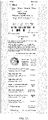
- the exemplary user interface shown in FIG. 2C presents the first physiological data and the second physiological data.
- the current date is June 21, 2018.
- a sleep duration during the night is 8 hours and 40 minutes.
- the first physiological data includes: a deep sleep duration being 2 hours and a light sleep duration being 3 hours and 10 minutes.
- the second physiological data includes: a rapid eye movement duration being 3 hours and 30 minutes.
- the electronic device 100 can display as many physiological feature parameters as possible on the basis of ensuring that correct physiological data is displayed, thereby improving the user experience.
- “June 21, 2018” displayed on the user interfaces shown in FIG. 2A to FIG. 2C are only a schematic description, and does not constitute a limitation to the technical solution of this application.
- sleep stage data before or after "June 21, 2018” may be displayed on the user interface.
- the sleep stage data on June 20, 2018 may be displayed on the user interface.
- the sleep stage data on June 22, 2018 may be displayed on the user interface.
- the electronic device 100 may further generate and display heart rhythm statistics of the user.
- the user may view heart rhythm statistics for one day by triggering "Day” on the user interface, and may further view heart rhythm statistics for a week by triggering "Week” on the user interface.
- the heart rhythm statistics may include, for example, whether the heart rhythm is abnormal, a change curve of the heart rhythm, the irregular heart rhythm, and the time when the irregular heart rhythm occurs.
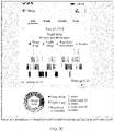
- FIG. 2D shows a user interface of exemplary heart rhythm statistics.
- the heart rhythm statistics are, for example, heart rhythm statistics of the user on March 1, 2019.
- the heart rhythm statistics include data such as a statistical result "No abnormality”, "Average heart rhythm: 68 beats/minute”, a heart rhythm change curve of the user on March 1, 2019, “Irregular heart rhythm: 4 times”, “No abnormality: 54 times”, “Irregular heart rhythm is 70 bmp.
- the time of occurrence is 03:31:12 on March 1, 2019", and "Non-abnormal heart rhythm is 65 bmp". The details are not described in this application.
- FIG. 2E shows a user interface of exemplary heart rhythm statistics.
- the heart rhythm statistics are, for example, heart rhythm statistics for the week from February 25, 2019 to March 3, 2019.
- the heart rhythm statistics for the week include data such as "Irregular heart rhythm ratio: 1/58", “Histogram and graph of the heart rhythm for each day of the week”, “Irregular heart rhythm: 10 times”, and "No abnormality: 260 times”. The details are not described in this application.
- the electronic device 100 may further count and display the heart rhythm of the user at various stages, thereby reminding the user of the health status at any time, and improving the user experience.
- FIG. 2A to FIG. 2E are only schematic descriptions, and do not constitute a limitation to the protection scope of the embodiments of this application.
- the data presented in the user interface may be alternatively other physiological data of the user, and the expression form of the data presented in the user interface may be alternatively other forms, and the details are not described herein again.
- the user interfaces shown in FIG. 2A to FIG. 2E are user interfaces using a smartphone as an example.
- the electronic device 100 may further display the physiological data on the display screen of the electronic device 100. It should be understood that areas of display screens of different devices may be different, so that quantities of data displayed on user interfaces of different electronic devices are different, which is not limited in this application.
- the data display method of this application is exemplarily described below from the perspective of the electronic device 100.
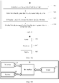
- FIG. 3 shows a data display method 10.
- the data display method 10 (referred to as the method 10 below) includes the following steps: Step S11: Acquire pulse data within a first time period.
- the first time period may be any time period of a day, for example, from 11 o'clock to 13 o'clock in a day, or from 22 o'clock in a day to 7 o'clock in a next day.
- a length of the first time period is a first duration.
- the shortest first duration may be, for example, 1 minute
- the longest first duration may be, for example, 24 hours, which is not limited in this application.
- the pulse data is, for example, PPG data.
- the sensor 121 for detecting physiological signals of the human body is, for example, a photoelectric sensor, and the photoelectric sensor may acquire the pulse data of the user.
- the photoelectric sensor is, for example, a PPG sensor.
- the PPG sensor when the heart of the user contracts, the blood volume of the blood vessels increases, the amount of light absorption increases correspondingly, and correspondingly, the light intensity detected by the PPG sensor is relatively low; and when the heart of the user relaxes, the blood volume of the blood vessels decreases, and the light intensity detected by the PPG sensor is relatively high.
- the PPG sensor may detect the light intensity with the pulsating change, and further, the PPG sensor may convert the light intensity change signal into a digital electrical signal.
- the digital electrical signal may be referred to as a PPG signal or PPG data, that is, the pulse data described in this solution.
- the electronic device 100 may alternatively acquire the pulse data through an ECG sensor. The details are not described herein in this application.
- Step S12 Determine that the pulse data includes abnormal pulse data.
- the abnormal pulse data is pulse data corresponding to arrhythmia.
- the photoelectric sensor After acquiring the pulse data, the photoelectric sensor transmits the pulse data to the processor 110.
- the processor 110 detects whether there is arrhythmia pulse data in the pulse data, and if there is arrhythmia pulse data in the pulse data, the processor 110 may count an accumulated duration of arrhythmia of the user to obtain a second duration.
- the processor 110 may preset an arrhythmia preliminary screening algorithm, and then use the arrhythmia preliminary screening algorithm to detect whether there is abnormal pulse data in the pulse data.
- the arrhythmia preliminary screening algorithm is any algorithm that can screen pulse data for arrhythmia, such as a support vector machine (support vector machine, SVM) algorithm, a threshold method, a machine learning method, and a deep learning method. This is not limited in this application.
- the processor 110 divides the PPG data within the first time period into k data segments, where k is greater than or equal to 1, a duration corresponding to each data segment is a third duration, the third duration is less than the second duration, and the third duration is, for example, one minute.
- the processor 110 then uses the SVM algorithm to separately detect whether each data segment is abnormal data.
- the SVM algorithm determines a detection result by calculating a distance between each data segment and a decision plane in a feature space. For example, y t (w ⁇ x t - b ) ⁇ 1 is a condition correspondence that each data segment should meet, and arg min w b 1 2 ⁇ w ⁇ 2 defines values of w and b when y t (w ⁇ x t - b ) ⁇ 1 reaches a minimum value.
- x t refers to a t th data segment in the k data segments, such as a heart rhythm variability feature and an entropy feature.
- y t refers to pulse index data indicating whether the heart rhythm is abnormal.
- y t when detecting whether a data segment is abnormal pulse data, y t is index data corresponding to arrhythmia; in some other embodiments, when detecting whether a data segment is normal pulse data, y t is index data corresponding to normal heart rhythm.
- y t is pulse index data corresponding to arrhythmia
- y t is pulse index data corresponding to normal heart rhythm
- the processor 110 may count an accumulated duration of the abnormal pulse data to obtain a second duration. Further, the processor 110 may determine whether a ratio of the second duration to the first duration is greater than a preset value, and then perform the following steps according to a determination result.
- Step S13 Determine a ratio of a second duration to the first duration.
- Step S14 Display first physiological data when the ratio is greater than a first preset value.
- the first preset value is a value greater than 0 and less than 1, such as 5%, or may be expressed as 0.05.
- the first physiological data includes a first physiological feature parameter, exemplarily, as described in the embodiment corresponding to FIG. 2B , and the details are not described herein again.
- the processor 110 may parse the pulse data by using an acceleration (acceleration, ACC) detection method, to obtain the first physiological data of the user.
- an acceleration acceleration, ACC
- this implementation method can ensure the accuracy of the obtained physiological data.
- the processor 110 may parse abnormal pulse data in the pulse data by using the ACC detection method, to obtain first physiological data; and parse data except the abnormal pulse data in the pulse data by using a cardiopulmonary coupling (cardiopulmonary coupling, CPC) detection method or a heart rate variability (heart rate variability, HRV) detection method, to obtain second physiological data, where the second physiological data includes a second physiological feature parameter.
- CPC cardiopulmonary coupling
- HRV heart rate variability
- the second preset value is greater than the first preset value and less than 1, and the second preset value is, for example, 30%, or may be expressed as 0.3.
- the display examples of the first physiological data and the second physiological data are, for example, as described in the embodiment corresponding to FIG. 2C , and the details are not described herein again.
- the processor 110 may process the pulse data to obtain reconstructed pulse data, and then generate third physiological data, where the third physiological data includes the first physiological feature parameter, a second physiological feature parameter, and a third physiological feature parameter.
- the third physiological data includes the first physiological feature parameter, a second physiological feature parameter, and a third physiological feature parameter.
- the processor 110 may delete the abnormal pulse data from the pulse data to obtain the reconstructed pulse data. In some other embodiments, the processor 110 may modify the corresponding abnormal pulse data according to non-abnormal pulse data adjacent to the abnormal pulse data, to obtain the reconstructed pulse data.
- the CPC detection method is used as an example below to exemplarily describe the implementation process of obtaining the third physiological data by the electronic device 100.
- the pulse data described in step S11 is PPG data.
- the specific process for the processor to generate the third physiological data includes the following steps: Step 1: The processor 110 may extract an R peak to R peak interval (R peak to R peak interval, RR) sequence from the PPG data, and then the processor 110 may extract a respiratory signal sequence from the RR sequence.
- R peak to R peak interval R peak to R peak interval
- ECG-derived respiratory ECG-derived respiratory
- EDR ECG-derived respiratory
- Step 2 The processor 110 uses a sliding window to delete abnormal sample points in the RR sequence to obtain a reconstructed RR sequence.
- Step 3 The processor 110 uses an empirical mode decomposition algorithm to decompose the reconstructed RR sequence and the EDR signal sequence, and calculates a coherence and cross power spectrum of the decomposed RR sequence and the decomposed EDR signal sequence.
- Step 4 The processor 110 calculates the third physiological data according to a coherent and cross power spectrum result.
- the processor 110 may further obtain heart rhythm statistics of the user in different time periods according to statistics of the heart rhythm data of the user.
- the heart rhythm statistics are described in the embodiment shown in FIG. 2D or FIG. 2E .
- the processor 110 executes a display function and displays physiological data involved in the method 10 through the display screen 13, to obtain data of the user interface shown in any one of FIG. 2A to FIG. 2E .
- the processor 110 may send the physiological data involved in the method 10 to another electronic device through the wireless communication module 140, and the another electronic device may display the corresponding physiological data to obtain the user interface shown in any one of FIG. 2A to FIG. 2E .
- the technical solution of this application may further detect pressure data of the user, and correspondingly, the HRV detection method, a scale questionnaire method, a behavior observation method, or the like may be used. The details are not described herein in this application.
- the electronic device calculates a ratio of an accumulated duration of the abnormal pulse data to a total duration of the pulse data, and further determines whether the ratio is greater than a first preset value.
- the electronic device displays first physiological data of a user, where the first physiological data includes a first physiological feature parameter, thereby ensuring that the physiological data displayed to the user is correct, and improving the user experience.
- the electronic device 100 may implement the foregoing corresponding functions in the form of functional modules.
- the electronic device may include an acquisition module, a processing module, and a display module.
- the acquisition module may be configured to perform the acquisition of pulse data in any of the embodiments shown in FIG. 3 above.
- the display module may be configured to perform the display of physiological data in any of the embodiments shown in FIG. 3 above.
- the processing module may be configured to perform operations other than the acquisition of pulse data and the display of physiological data in any of the embodiments shown in FIG. 3 above.
- the electronic device 40 includes a sensor 401, a processor 402, and a display 403.
- the sensor 401 may perform the acquisition of pulse data in any of the embodiments shown in FIG. 3 above.
- the display 403 may be configured to perform the display of physiological data in any of the embodiments shown in FIG. 3 above.
- the processor 402 may be configured to perform operations other than the acquisition of pulse data and the display of physiological data in any of the embodiments shown in FIG. 3 above.
- the sensor 401 may acquire pulse data within a first time period, a length of the first time period being a first duration.
- the processor 402 may be configured to: determine that the pulse data includes abnormal pulse data, the abnormal pulse data being pulse data corresponding to arrhythmia; and determine a ratio of a second duration to the first duration, the second duration being an accumulated duration of the abnormal pulse data.
- the display 403 may be configured to display first physiological data when the ratio is greater than a first preset value, the first preset value being a value greater than 0 and less than 1, the first physiological data including a first physiological feature parameter.
- FIG. 4A is a description of the electronic device of this application from the perspective of an independent functional entity.
- each independently running functional entity may be integrated into one hardware entity.
- the electronic device 41 may include a processor 411, a sensor 412, and a memory 413.
- the memory 413 may be configured to store a program/code preinstalled by the electronic device 41, or may store code executed by the processor 411, and the like.
- the electronic device 41 of this application may correspond to the electronic device in the embodiments corresponding to FIG. 3 of this application, where the sensor 412 is configured to perform the acquisition of pulse data in any of the embodiments shown in FIG. 3 , and the processor 411 is configured to perform other processing of the electronic device other than the acquisition of pulse data in any of the embodiments shown in FIG. 3 . Details are not described herein again.
- this application further provides a computer storage medium.
- the computer storage medium disposed in any device may store a program, and when the program is executed, some or all of the steps of the embodiments of the data display method provided in FIG. 3 may be performed.
- the storage medium in any device may be a magnetic disk, an optical disc, a read-only memory (read-only memory, ROM), a random access memory (random access memory, RAM), or the like.
- the processor may be a central processing unit (central processing unit, CPU), a network processor (network processor, NP), or a combination of a CPU and an NP.
- the processor may further include a hardware chip.
- the hardware chip may be an application-specific integrated circuit (application-specific integrated circuit, ASIC), a programmable logic device (programmable logic device, PLD), or a combination thereof.
- ASIC application-specific integrated circuit
- PLD programmable logic device
- the foregoing PLD may be a complex programmable logic device (complex programmable logic device, CPLD), a field-programmable gate array (field-programmable gate array, FPGA), a generic array logic (generic array logic, GAL), or any combination thereof.
- the memory may include a volatile memory (volatile memory), for example, a random-access memory (random-access memory, RAM).
- volatile memory volatile memory
- RAM random-access memory
- non-volatile memory non-volatile memory
- ROM read-only memory
- flash memory flash memory
- HDD hard disk drive
- solid-state drive solid-state drive
- SSD solid-state drive
- the sensor may include a sensor that detects a body shape change of the user, such as an ACC sensor and a motion sensor; the sensor may alternatively include a photoelectric sensor, such as a PPG sensor, an ambient light sensor, and an ECG sensor; and the sensor may alternatively include another high-sensitivity bioelectrical sensor, such as a bio-impedance sensor.
- a sensor that detects a body shape change of the user such as an ACC sensor and a motion sensor
- the sensor may alternatively include a photoelectric sensor, such as a PPG sensor, an ambient light sensor, and an ECG sensor
- the sensor may alternatively include another high-sensitivity bioelectrical sensor, such as a bio-impedance sensor.
- FIG. 4B may further include a bus interface.
- the bus interface may include any quantity of interconnected buses and bridges. Specifically, the buses and the bridges link various circuits of one or more processors represented by the processor and a memory represented by the memory.
- the bus interface may further link various other circuits such as a peripheral device, a voltage stabilizer, and a power management circuit. These are known in the art. Therefore, no details are further described in this specification.
- the bus interface provides an interface.
- the sensor provides a unit for acquiring biological data of the user.
- the processor is responsible for bus architecture management and general processing.
- the memory may store messages used by the processor when the processor performs an operation.
- the various illustrative logical units and circuits described in the embodiments of this application may implement or operate the described functions by using a general purpose processor, a digital signal processor, an application-specific integrated circuit (ASIC), a field programmable gate array (FPGA) or other programmable logic devices, discrete gate or transistor logic, discrete hardware components, or a design of any combination thereof.
- the general purpose processor may be a microprocessor.
- the general purpose processor may be any conventional processor, controller, microcontroller, or state machine.
- the processor may also be implemented through a combination of computing devices, for example, a combination of a digital signal processor and a microprocessor, a plurality of microprocessors, one or more microprocessors in conjunction with a digital signal processor core, or any other such configuration.
- the steps of the method or algorithm described in the embodiments of this application may be directly embedded in hardware, in a software unit executed by a processor, or in a combination thereof.
- the software unit may be stored in a RAM, a flash memory, a ROM, an EPROM, an EEPROM, a register, a hard disk, a removable disk, a CD-ROM, or any other form of storage medium in the art.
- the storage medium may be connected to the processor such that the processor can read information from the storage medium and write information to the storage medium.
- the storage medium may be integrated in the processor.
- the processor and the storage medium may be disposed in the ASIC, and the ASIC may be disposed in UE.
- the processor and the storage medium may be alternatively disposed in different components of the UE.
- All or some of the foregoing embodiments may be implemented by using software, hardware, firmware, or any combination thereof.
- implementation may be entirely or partially performed in the form of a computer program product.
- the computer program product includes one or more computer instructions.
- the computer may be a general-purpose computer, a dedicated computer, a computer network, or other programmable apparatuses.
- the computer instructions may be stored in a computer-readable storage medium or may be transmitted from a computer-readable storage medium to another computer-readable storage medium.
- the computer instructions may be transmitted from a website, computer, server, or message center to another website, computer, server, or message center in a wired (for example, a coaxial cable, an optical fiber, or a digital subscriber line (DSL)) or wireless (for example, infrared, radio, or microwave) manner.
- the computer-readable storage medium may be any usable medium accessible by a computer, or a message storage device, such as a server or a message center, integrating one or more usable media.
- the usable medium may be a magnetic medium (for example, a floppy disk, a hard disk, or a magnetic tape), an optical medium (for example, a DVD), a semiconductor medium (for example, a solid state disk (solid state disk, SSD)), or the like.
- a magnetic medium for example, a floppy disk, a hard disk, or a magnetic tape
- an optical medium for example, a DVD
- a semiconductor medium for example, a solid state disk (solid state disk, SSD)
Landscapes
- Health & Medical Sciences (AREA)
- Life Sciences & Earth Sciences (AREA)
- Engineering & Computer Science (AREA)
- Cardiology (AREA)
- Surgery (AREA)
- Public Health (AREA)
- Biomedical Technology (AREA)
- Heart & Thoracic Surgery (AREA)
- Medical Informatics (AREA)
- Molecular Biology (AREA)
- Physics & Mathematics (AREA)
- Animal Behavior & Ethology (AREA)
- General Health & Medical Sciences (AREA)
- Biophysics (AREA)
- Veterinary Medicine (AREA)
- Pathology (AREA)
- Physiology (AREA)
- Signal Processing (AREA)
- Human Computer Interaction (AREA)
- Ophthalmology & Optometry (AREA)
- Measuring And Recording Apparatus For Diagnosis (AREA)
- Measuring Pulse, Heart Rate, Blood Pressure Or Blood Flow (AREA)
Abstract
Description
- This application relates to the field of electronic technologies, and in particular, to a data display method and an electronic device.
- Wearable devices (for example, smart watches and smart bands) can detect physiological data of a human body such as sleep stage data, pressure index data, and blood pressure. The sleep stage data is used as an example. A sleep state of the human body may be controlled by autonomic nerves of the human body, and an autonomic nerve function of the human body may be reflected by pulse data of the human body. Based on this, a wearable device can detect and display the sleep stage data of the human body, for example, by detecting the pulse data of the human body.
- However, arrhythmia affects the pulse data, and the corresponding pulse data during arrhythmia is not controlled by an autonomic nervous system. Therefore, if a user has arrhythmia, the sleep stage data detected and displayed by the wearable device is incorrect data.
- This application provides a data display method and an electronic device, which can resolve the problem that displayed data is incorrect data.
- According to a first aspect, this application provides a data display method, including: acquiring pulse data within a first time period, a length of the first time period being a first duration; determining that the pulse data includes abnormal pulse data, the abnormal pulse data being pulse data corresponding to arrhythmia; determining a ratio of a second duration to the first duration, the second duration being an accumulated duration of the abnormal pulse data; and displaying first physiological data when the ratio is greater than a first preset value, the first preset value being a value greater than 0 and less than 1, the first physiological data including a first physiological feature parameter.
- After the electronic device determines that the acquired pulse data includes the abnormal pulse data, in order to quantify a relative length of the accumulated duration of the arrhythmia, the ratio of the second duration to the first duration is determined. The first duration is the length of the first time period, and the second duration is the accumulated duration of the abnormal pulse data. When the ratio is greater than the first preset value, it may be considered that the accumulated duration of the arrhythmia is relatively long, and the electronic device may display the first physiological data of a user, the first physiological data including the first physiological feature parameter. In this way, correct physiological data can be displayed when the user has a certain degree of arrhythmia symptoms.
- In a possible design, the first physiological data and second physiological data are displayed when the ratio is greater than the first preset value and less than or equal to a second preset value, the second preset value being greater than the first preset value and less than 1, the second physiological data including a second physiological feature parameter. With this implementation, the electronic device can display as many physiological feature parameters as possible on the basis of ensuring that correct physiological data is displayed, thereby improving the user experience.
- In a possible design, third physiological data is displayed when the ratio is less than or equal to the first preset value, the third physiological data including the first physiological feature parameter, a second physiological feature parameter, and a third physiological feature parameter. When the ratio is less than or equal to the first preset value, it indicates that the accumulated duration of arrhythmia of the user is relatively short. Correspondingly, the electronic device can display more physiological feature parameters of the user. This can not only ensure the correctness of the displayed physiological data, but also makes the displayed physiological data more detailed.
- In a possible design, before the displaying first physiological data, the method further includes: parsing the pulse data by using an acceleration ACC detection method to obtain the first physiological data. In this application, when there is a particular amount of abnormal pulse data (the ratio is greater than the first preset value) in the pulse data, correct physiological data cannot be obtained by parsing the pulse data by using a cardiopulmonary coupling (cardiopulmonary coupling, CPC) detection method or a heart rate variability (heart rate variability, HRV) detection method. Therefore, the electronic device parses the pulse data by using an acceleration (acceleration, ACC) detection method, thereby obtaining correct physiological data.
- In a possible design, before the displaying the first physiological data and second physiological data, the method further includes: parsing the abnormal pulse data in the pulse data by using an acceleration ACC detection method to obtain the first physiological data; and parsing data in the pulse data except the abnormal pulse data by using a cardiopulmonary coupling CPC detection method to obtain the second physiological data. In some embodiments, when the ratio is greater than the first preset value and less than or equal to the second preset value, the electronic device may parse the abnormal pulse data in the pulse data by using the ACC detection method to obtain the first physiological data, and parse the non-abnormal pulse data in the pulse data by using the CPC detection method to obtain the second physiological data, thereby displaying as many physiological feature parameters as possible on the basis of ensuring that correct physiological data is displayed.
- In a possible design, before the displaying third physiological data, the method further includes: processing the abnormal pulse data in the pulse data to obtain reconstructed pulse data; and parsing the reconstructed pulse data by using a CPC detection method to obtain the third physiological data. In this application, when there are relatively few abnormal pulse data in the pulse data (the ratio is less than or equal to the first preset value), the electronic device may obtain the third physiological data according to most of the non-abnormal pulse data. Based on this, the electronic device may process the abnormal pulse data in the pulse data to obtain the reconstructed pulse data, where the reconstructed pulse data does not include the abnormal pulse data. Further, the electronic device parses the reconstructed pulse data by using the CPC detection method to obtain the third physiological data, so that correct and detailed physiological data can be obtained.
- In a possible design, the processing the abnormal pulse data in the pulse data to obtain reconstructed pulse data includes: deleting the abnormal pulse data from the pulse data to obtain the reconstructed pulse data; or modifying the abnormal pulse data according to non-abnormal pulse data adjacent to the abnormal pulse data, to obtain the reconstructed pulse data. With this implementation, the electronic device can obtain data that does not include the abnormal pulse data according to the pulse data, and can further use the CPC detection method to generate the third physiological data.
- In a possible design, the determining that the pulse data includes abnormal pulse data includes: dividing the pulse data into k data segments, k being greater than or equal to 1, a duration corresponding to each data segment in the k data segments being a third duration, the third duration being less than the second duration; and determining whether each data segment in the k data segments satisfies a correspondence yt (w × xt - b) ≥ 1, t = 1, 2, 3, ..., k, w being a normal vector of support vectors, b being a deviation value of a decision plane, xt being a tth data segment in the k data segments, yt being corresponding pulse index data indicating whether heart rhythm is abnormal; and if yt is pulse index data corresponding to arrhythmia, determining that the data segment is the abnormal pulse data when the data segment satisfies the correspondence yt (w × xt - b) ≥ 1. With this implementation, the electronic device can determine whether the pulse data includes abnormal pulse data, and further, the electronic device can display different physiological data according to the included abnormal pulse data.
- In a possible design, the first physiological feature parameter includes a deep sleep duration and a light sleep duration; the second physiological feature parameter includes a rapid eye movement duration; and the third physiological feature parameter includes at least one of a deep sleep ratio, a light sleep ratio, a rapid eye movement ratio, a deep sleep continuity score, a sleep quality score, and a breathing quality score. As can be seen, the electronic device can display different physiological feature parameters according to a relative amount of abnormal pulse data, thereby ensuring the correctness of the displayed physiological data.
- According to a second aspect, this application provides an electronic device. The electronic device has a function of implementing behavior of the electronic device in the foregoing method. The function may be implemented by using hardware or may be implemented by using hardware executing corresponding software. The hardware or software includes one or more modules corresponding to the foregoing function. In a possible design, a structure of the electronic device includes a sensor, a processor, and a display. The processor is configured to process a corresponding function in the foregoing method performed by the electronic device. The sensor is configured to implement the acquisition of the pulse data by the electronic device. The display is configured to implement the display of the physiological data by the electronic device. The electronic device may further include a memory. The memory is configured to be coupled to the processor and store necessary program instructions and data for the electronic device.
- According to a third aspect, this application provides a computer storage medium. The computer storage medium stores instructions, the instructions, when run on a computer, causing the computer to perform part or all of the steps of the data display method in the first aspect and various possible implementations of the first aspect.
- According to a fourth aspect, this application provides a computer program product, the computer program product, when run on a computer, causing the computer to perform part or all of the steps of the data display method in the first aspect and various possible implementations of the first aspect.
- To resolve the problems in the prior art, in the technical solution of this application, after determining that acquired pulse data includes abnormal pulse data, the electronic device calculates a ratio of an accumulated duration of the abnormal pulse data to a total duration of the pulse data, and further determines whether the ratio is greater than a first preset value. When the ratio is greater than the first preset value, the electronic device displays first physiological data of a user, where the first physiological data includes a first physiological feature parameter, thereby ensuring that the physiological data displayed to the user is correct, and improving the user experience.
-
-
FIG. 1A is an exemplary schematic structural diagram of asmart watch 10 according to this application; -
FIG. 1B is an exemplary schematic structural diagram of anelectronic device 100 according to this application; -
FIG. 1C is an exemplary schematic diagram of a display screen inFIG. 1A according to this application; -
FIG. 2A is a schematic diagram of a first implementation of a user interface according to this application; -
FIG. 2B is a schematic diagram of a second implementation of a user interface according to this application; -
FIG. 2C is a schematic diagram of a third implementation of a user interface according to this application; -
FIG. 2D is a schematic diagram of a fourth implementation of a user interface according to this application; -
FIG. 2E is a schematic diagram of a fifth implementation of a user interface according to this application; -
FIG. 3 is an exemplary method flowchart of adata display method 10 according to this application; -
FIG. 4A is an exemplary schematic structural diagram of anelectronic device 40 according to this application; and -
FIG. 4B is an exemplary schematic structural diagram of anelectronic device 41 according to this application. - The following clearly describes technical solutions of this application with reference to the accompanying drawings in this application.
- Terms used in the following embodiments of this application are only intended to describe particular embodiments, and are not intended to limit this application. As used in this specification and the claims of this application, a singular expression form, "one", "a", "said", "foregoing", "the", or "this", is intended to also include a plural expression form, unless clearly indicated to the contrary in the context. It should be understood that although the terms first, second, etc. may be used in the following embodiments to describe a certain type of object, the object should not be limited to the terms. The terms are only used to distinguish specific objects of this type of objects. For example, in the following embodiments, the terms first, second, etc. may be used to describe the duration, but the duration should not be limited to the terms. The terms are only used to distinguish between different lengths of time. In the following embodiments, the terms first, second, etc. may be used to describe other types of objects in the same way, and the details are not repeated herein. In addition, the term "and/or" used in this application indicates and includes any or all possible combinations of one or more listed items.
- The following embodiments introduce an electronic device and an embodiment of a data display method related to the electronic device.
- In some embodiments, the electronic device described in this application may be a wearable device, and the wearable device may be any device with a function of detecting physiological data of a user. The wearable device may be, for example, a smart watch, a smart band, or a bracelet that is supported by a wrist, or may be, for example, a smart shoe or a sock that is supported by a foot, or another product worn on a leg in the future, or may be smart glasses, a smart helmet, and a headband supported by a head. In some other embodiments, the electronic device described in this application may be another device configured to detect a physiological parameter of the user. For example, the electronic device is a device that uses radar waves to detect pulse waves of the user. In another example, the electronic device is a device that uses a mattress to acquire a ballistocardiogram signal of the user. In another example, the electronic device is a device that detects pulse waves by using a camera of a mobile phone to take pictures of bare skin of the user. This is not limited in this application.
- This application relates to a "user interface (user interface, UI)" configured to display data. The UI is a medium interface for interaction and information exchange between an application or operating system and a user, and implements the conversion between an internal form of information and a form of the information acceptable to the user. The user interface of the application is source code written in a specific computer language such as java and the extensible markup language (extensible markup language, XML). The interface source code is parsed and rendered on a terminal device, and is finally presented as content that can be recognized by the user, such as a picture, a text, a button and other controls. A control (control), also referred to as a widget (widget), is a basic element of the user interface. Typical controls include a toolbar (toolbar), a menu bar (menu bar), a text box (text box), a button (button), a scrollbar (scrollbar), a picture, and a text. The attributes and content of the controls in the interface are defined by tags or nodes. For example, XML specifies the controls included in the interface through nodes such as <Textview>, <ImgView>, and <VideoView>. One node corresponds to one control or attribute in the interface, and the node is parsed and rendered, and is then presented as user-visible content. In addition, interfaces of many applications, such as hybrid applications (hybrid application), usually further include web pages. A web page, also referred to as a page, may be understood as a special control embedded in an application interface. The web page is source code written in a specific computer language, such as the HyperText Markup Language (HyperText Markup Language, HTML), cascading style sheets (cascading style sheets, CSS), and java scripts (JavaScript, JS). The source code of the web page may be loaded and displayed by a browser or a web page display component with similar functions to the browser as content that can be recognized by the user. The specific content included in the web page is also defined by tags or nodes in the source code of the web page. For example, HTML defines elements and attributes of the web page through <p>, <img>, <video>, and <canvas>.
- Some of physiological functions of a human body such as sleep and breathing are controlled by autonomic nerves, and the role of the autonomic nerves may be reflected in the heart rhythm of the human body. Generally, a blood volume in blood vessels increases under the action of heart contraction, and the blood volume in the blood vessels decreases under the action of heart relaxation. Based on this, the heart rhythm of the human body may be reflected in the pulse of the human body. Further, in actual operation, the electronic device may detect physiological data of the user such as blood pressure, blood oxygen, brain oxygen, muscle oxygen, blood sugar, pulse rate, and respiration rate by acquiring and detecting pulse data (also referred to as pulse wave data or photo plethysmo graphy (photo plethysmo graphy, PPG) data) of the user. However, arrhythmia (such as atrial fibrillation) is not controlled by an autonomic nervous system. If the user has symptoms of arrhythmia, the pulse data acquired by the electronic device includes pulse data corresponding to the arrhythmia, and consequently, the physiological data of the user parsed and displayed by the electronic device is incorrect.
- This application provides a data display method and an electronic device. Even if a user using the electronic device has symptoms of arrhythmia, the electronic device can still parse and display correct physiological data of the user according to acquired pulse data, thereby improving the user experience.
- The following describes an exemplary
electronic device 100 involved in an embodiment of this application. - The
electronic device 100 involved in this application may be, for example, asmart watch 10 shown inFIG. 1A , and thesmart watch 10 includes awatch body 11 and abracelet 12. Thebracelet 12 is configured to enable the user to wear thesmart watch 10, and thewatch body 11 is configured to implement some or all of the embodiments of the data display method involved in this application. - It may be understood that the
smart watch 10 shown inFIG. 1A constitutes no specific limitation on theelectronic device 100. In some other embodiments of this application, theelectronic device 100 may be a smart band, smart glasses, a smart helmet, or the like, and the details are not described herein again. -
FIG. 1B is a schematic structural diagram of theelectronic device 100. The devices shown inFIG. 1B may be disposed in thewatch body 11 of thesmart watch 10 shown inFIG. 1A . - The
electronic device 100 may include aprocessor 110, asensor 120, amemory 130, awireless communication module 140, a microphone (microphone, MIC) 150, apower supply 160, apower management module 170, and the like. Thewireless communication module 140 may include a wireless fidelity (wireless fidelity, Wi-Fi) module 141, aBluetooth module 142, a near field communication (near field communication, NFC)module 143, and the like. Thesensor 120 may include aphotoelectric sensor 121 for detecting physiological signals of a human body, amotion sensor 122, and an ambientlight sensor 123. - It may be understood that the schematic structure in this application constitutes no specific limitation on the
electronic device 100. In some other embodiments of this application, theelectronic device 100 may include more or fewer components than those shown in the figure (for example, a display screen and a gyroscope), or some components may be combined, or some components may be split, or components are arranged in different manners. The components shown in the figure may be implemented by hardware, software, or a combination of software and hardware. - The
processor 110 is configured to perform system scheduling, such as calling the Wi-Fi module 141, theBluetooth module 142, and theNFC module 143 to support the processing of themicrophone 150, and the like. Theprocessor 110 is further configured to: detect, according to data inputted by thesensor 120, whether the user has arrhythmia, and then use corresponding detection methods for different scenarios to detect physiological data of the user. - The
photoelectric sensor 121 for detecting physiological signals of the human body may be, for example, a PPG sensor or an electrocardiogram (electrocardiogram, ECG) sensor. Thephotoelectric sensor 121 for detecting physiological signals of the human body may be configured on a side of theelectronic device 100 that is in contact with skin of the user when the electronic device is worn. Thephotoelectric sensor 121 for detecting physiological signals of the human body may be configured to, for example, detect changes in light intensity, and convert the detected changes in light intensity into digital electrical signals, such as PPG signals. Thephotoelectric sensor 121 for detecting physiological signals of the human body may be further configured to detect electrocardiographic signals, vibration signals, bio-impedance signals, and the like of the human body. Further, thephotoelectric sensor 121 for detecting physiological signals of the human body is further configured to send the detected signals, such as the PPG signals, the electrocardiogram signals, the vibration signals, and the bio-impedance signals to theprocessor 110, so that theprocessor 110 obtains pulse data of the user from the corresponding signals, and further measures the physiological data of the user according to the obtained pulse data. - The
motion sensor 122 may be, for example, an acceleration sensor. Themotion sensor 122 is configured to detect an acceleration value of theelectronic device 100 in each direction (generally three axes). - The ambient
light sensor 123 is configured to detect intensity of ambient light and convert the intensity of the ambient light into a data electrical signal. - With reference to
FIG. 1A , the PPG sensor or the ECG sensor may be disposed on the inner side of thewatch body 11. After the user wears thesmart watch 10, the PPG sensor or the ECG sensor may be in contact with the body of the user. The inner side of thewatch body 11 is the side in contact with the body of the user when the user wears thesmart watch 10. - The
memory 130 is configured to store a software program and data. Theprocessor 110 implements the embodiments of the data display method of this application by running the software program. The data is used for providing support for theprocessor 110 to run the software program. Thememory 130 may include a program storage area and a data storage area. The program storage area may store an operating system, and an application required by at least one function (such as a data display function and a sound playback function). The data storage area may store data created according to use of theelectronic device 100, an algorithm required for theprocessor 110 to perform physiological data detection, and the like. In addition, the memory may include a high-speed random access memory, and may further include a non-volatile memory, for example, a magnetic disk storage device, a flash memory device, or another volatile solid-state storage device. - The
wireless communication module 140 may provide a solution to wireless communication applied to theelectronic device 100, for example, a wireless local area network (wireless local area networks, WLAN) (for example, a Wi-Fi network), Bluetooth (Bluetooth, BT), a global navigation satellite system (global navigation satellite system, GNSS), NFC, and an infrared (infrared, IR) technology. Thewireless communication module 140 may be one or more components into which at least one communication processing module is integrated. Thewireless communication module 140 receives an electromagnetic wave through an antenna, performs frequency modulation and filtering processing on the electromagnetic wave signal, and sends the processed signal to theprocessor 110. Thewireless communication module 140 may further receive a to-be-sent signal from theprocessor 110, perform frequency modulation and amplification on the to-be-sent signal, and convert the signal into an electromagnetic wave through an antenna and radiate the signal. In some embodiments, the solution to wireless communication provided by thewireless communication module 140 can enable theelectronic device 100 to exchange data with other electronic devices (such as mobile phones and tablet computers). For example, the physiological data of the user may be displayed through other electronic devices. - The
microphone 150, also referred to as a mike, may convert acquired sound signals into electrical signals, and the electrical signals are received by an audio circuit and converted into audio data. The audio circuit may also convert audio data into electrical signals, and the electrical signals are transmitted to a speaker, and converted into sound signals by the speaker for output. - The
power management module 170 is configured to connect thepower supply 160 and theprocessor 110. Thepower management module 170 receives input of thepower supply 160 and supplies power to theprocessor 110, thesensor 120, thememory 130, thewireless communication module 140, themicrophone 150, and other components. Thepower management module 170 may be further configured to monitor parameters of thepower supply 160 such as a capacity, a cycle count, and a state of health (electric leakage and impedance). - The
electronic device 100 may include a display screen, and the display screen is configured to display controls, data, images, and the like. The display screen includes a display panel. The display panel may be a liquid crystal display (liquid crystal display, LCD), an organic light-emitting diode (organic light-emitting diode, OLED), an active-matrix organic light emitting diode (active-matrix organic light emitting diode, AMOLED), a flexible light-emitting diode (flex light-emitting diode, FLED), a Miniled, a MicroLed, a Micro-oLed, quantum dot light emitting diodes (quantum dot light emitting diodes, QLED), and the like. - Exemplarily, the
display screen 13 of thesmart watch 10 may be shown inFIG. 1C . In some embodiments, thesmart watch 10 may display physiological data involved in this application on thedisplay screen 13. - The
electronic device 100 exemplarily shown inFIG. 1A to FIG. 1C may obtain pulse data of a user through thesensor 120, and theprocessor 110 then parses the pulse data to obtain physiological data of the user. Further, in some embodiments, the display screen of theelectronic device 100 displays various user interfaces described in the following embodiments. In some other embodiments, theprocessor 110 calls thewireless communication module 140 to send the physiological data of the user to another electronic device, to display various user interfaces described in the following embodiments through the another electronic device. - The following describes exemplary user interfaces in different scenarios of this application.
- In this application, if the user has no symptom of arrhythmia, or the user has symptoms of arrhythmia but an accumulated duration of the arrhythmia is relatively short, the
electronic device 100 may display more physiological data of the user. If the user has symptoms of arrhythmia and an accumulated duration of the arrhythmia is relatively long, theelectronic device 100 may display fewer physiological data of the user. - Exemplarily, to quantify a relative length of the accumulated duration of the arrhythmia, this application may use a ratio of the accumulated duration of the arrhythmia to a total duration of acquiring the pulse data as the basis for determining the accumulated duration of the arrhythmia. Based on this, "the accumulated duration of the arrhythmia is relatively short" indicates, for example, that the corresponding ratio is less than or equal to a first preset value, and "the accumulated duration of the arrhythmia is relatively long" indicates, for example, that the corresponding ratio is greater than the first preset value. The first preset value is a value greater than 0 and less than 1, for example, 5%. This is not limited in this application.
- In addition, for ease of description, in this application, the physiological data of the user is summarized into first physiological data, second physiological data, and third physiological data. The first physiological data includes a first physiological feature parameter; the second physiological data includes a second physiological feature parameter; and the third physiological data includes the first physiological feature parameter, a second physiological feature parameter, and a third physiological feature parameter.
- Exemplarily, display of sleep stage data of the user on a smartphone is used as an example below to introduce the user interface involved in this application. After the
electronic device 100 determines the sleep stage data of the user, the sleep stage data is, for example, sent to a smartphone, and the smartphone then presents the following user interface on a display screen of the smartphone. - The sleep of the user may include two states: non-rapid eye movement sleep (non-rapid eye movement sleep, NREM sleep) and rapid eye movement sleep (rapid eye movement sleep, REM sleep). The NREM sleep stage may further include four periods. For example, the first period is a falling asleep stage, the second period is a light sleep stage, the third period is a moderate sleep stage, and the fourth period is a deep sleep stage.
- The sleep stage data is used as an example. The first physiological feature parameter includes, for example, a deep sleep duration and a light sleep duration. The second physiological feature parameter includes, for example, a rapid eye movement duration. The third physiological feature parameter includes, for example, at least one of a deep sleep ratio, a light sleep ratio, a rapid eye movement ratio, a deep sleep continuity score, a sleep quality score, and a breathing quality score. Correspondingly, the first physiological data includes the deep sleep duration and the light sleep duration; the second physiological data includes the rapid eye movement duration; and the third physiological data includes at least one of the deep sleep ratio, the light sleep ratio, the rapid eye movement ratio, the deep sleep continuity score, the sleep quality score, and the breathing quality score.
- The exemplary user interface shown in
FIG. 2A presents the third physiological data. The current date is June 21, 2018. The user fell asleep at 22:20 on June 20, 2018 and woke up at 6:50 on June 21, 2018. A sleep duration during the night is 8 hours and 40 minutes. A curve of sleep stages in time periods during the sleep is presented. In this embodiment, the third physiological data further includes: a night sleep score of the user calculated by theelectronic device 100 being 81 with an evaluation attached, a deep sleep duration of the user being 1 hour and 40 minutes, a light sleep duration being 3 hours and 40 minutes, a rapid eye movement duration being 3 hours and 20 minutes, a proportion of a total duration of each sleep stage in the total sleep duration, a normal range of the total duration of each sleep stage, and analysis results. For example, a proportion of deep sleep being 20% is normal, and a proportion of rapid eye movement being 38% is slightly low. The third physiological data may even include time periods and durations of sporadic naps the day before the current date of the user, and a total sleep duration of the sporadic naps during the day and the night sleep. The details are not described herein in this application. - It should be pointed out that the user interface shown in
FIG. 2A presents the physiological data when the user has no arrhythmia symptoms. If the user has symptoms of arrhythmia and the corresponding ratio is less than or equal to the first preset value, the user interface may further display warning information in addition to the third physiological data. For example, a start moment corresponding to sleep data acquired by theelectronic device 100 is 22:30 on June 20, 2018, an end moment is 7:00 on June 21, 2018, and a total duration of the acquired sleep data is 8 hours and 30 minutes. A total duration of night sleep is, for example, 8 hours and 20 minutes (including deep sleep, light sleep, and rapid eye movement), and a total duration of arrhythmia is, for example, 10 minutes. In this scenario, the user interface may further present warning information such as "the user has slight arrhythmia". Other data in the user interface in this scenario is similar to that inFIG. 2A , and the details are not repeated herein. - The exemplary user interface shown in
FIG. 2B presents the first physiological data. A current date is June 21, 2018. The user fell asleep at 20:00 on June 20, 2018 and woke up at 9:32 on June 21, 2018. A sleep duration during the night is 8 hours and 40 minutes. A total duration of arrhythmia is 2 hours. A stage curve of deep sleep, light sleep, and wakefulness in each period is shown inFIG. 2B . A deep sleep duration is 3 hours and 20 minutes. A light sleep duration is 5 hours and 20 minutes. - As can be seen, when the user has no symptoms of arrhythmia or has symptoms of arrhythmia for a relatively short duration, the
electronic device 100 can display the first physiological feature parameter, the second physiological feature parameter, and the third physiological feature parameter of the user. When the user has symptoms of arrhythmia for a relatively long duration, theelectronic device 100 only displays the first physiological feature parameter of the user, thereby ensuring that the displayed physiological data is correct. - In some other embodiments, when the ratio is greater than the first preset value and less than the second preset value, the electronic device may further display the first physiological data and the second physiological data of the user. The second preset value is greater than the first preset value and less than 1, and the second preset value is, for example, 30%.
- The exemplary user interface shown in
FIG. 2C presents the first physiological data and the second physiological data. The current date is June 21, 2018. The user fell asleep at 22: 10 on June 20, 2018 and woke up at 8:30 on June 21, 2018. A sleep duration during the night is 8 hours and 40 minutes. The first physiological data includes: a deep sleep duration being 2 hours and a light sleep duration being 3 hours and 10 minutes. The second physiological data includes: a rapid eye movement duration being 3 hours and 30 minutes. - With this implementation, the
electronic device 100 can display as many physiological feature parameters as possible on the basis of ensuring that correct physiological data is displayed, thereby improving the user experience. - It may be understood that "June 21, 2018" displayed on the user interfaces shown in
FIG. 2A to FIG. 2C are only a schematic description, and does not constitute a limitation to the technical solution of this application. In actual use, when the user triggers the arrow on the left or right side of "June 21, 2018", sleep stage data before or after "June 21, 2018" may be displayed on the user interface. For example, when the user clicks on the arrow on the left of "June 21, 2018", the sleep stage data on June 20, 2018 may be displayed on the user interface. In another example, if "June 21, 2018" is not the current time, and the user clicks on the arrow on the right side of "June 21, 2018", the sleep stage data on June 22, 2018 may be displayed on the user interface. - Further, in some embodiments, the
electronic device 100 may further generate and display heart rhythm statistics of the user. Exemplarily, with reference to the user interfaces shown inFIG. 2A to FIG. 2C , the user may view heart rhythm statistics for one day by triggering "Day" on the user interface, and may further view heart rhythm statistics for a week by triggering "Week" on the user interface. The heart rhythm statistics may include, for example, whether the heart rhythm is abnormal, a change curve of the heart rhythm, the irregular heart rhythm, and the time when the irregular heart rhythm occurs. -
FIG. 2D shows a user interface of exemplary heart rhythm statistics. The heart rhythm statistics are, for example, heart rhythm statistics of the user on March 1, 2019. The heart rhythm statistics include data such as a statistical result "No abnormality", "Average heart rhythm: 68 beats/minute", a heart rhythm change curve of the user on March 1, 2019, "Irregular heart rhythm: 4 times", "No abnormality: 54 times", "Irregular heart rhythm is 70 bmp. The time of occurrence is 03:31:12 on March 1, 2019", and "Non-abnormal heart rhythm is 65 bmp". The details are not described in this application. -
FIG. 2E shows a user interface of exemplary heart rhythm statistics. The heart rhythm statistics are, for example, heart rhythm statistics for the week from February 25, 2019 to March 3, 2019. The heart rhythm statistics for the week include data such as "Irregular heart rhythm ratio: 1/58", "Histogram and graph of the heart rhythm for each day of the week", "Irregular heart rhythm: 10 times", and "No abnormality: 260 times". The details are not described in this application. - As can be seen, with this implementation, the
electronic device 100 may further count and display the heart rhythm of the user at various stages, thereby reminding the user of the health status at any time, and improving the user experience. - It may be understood that
FIG. 2A to FIG. 2E are only schematic descriptions, and do not constitute a limitation to the protection scope of the embodiments of this application. In some other embodiments, the data presented in the user interface may be alternatively other physiological data of the user, and the expression form of the data presented in the user interface may be alternatively other forms, and the details are not described herein again. - In addition, the user interfaces shown in
FIG. 2A to FIG. 2E are user interfaces using a smartphone as an example. In some other embodiments, theelectronic device 100 may further display the physiological data on the display screen of theelectronic device 100. It should be understood that areas of display screens of different devices may be different, so that quantities of data displayed on user interfaces of different electronic devices are different, which is not limited in this application. - The data display method of this application is exemplarily described below from the perspective of the
electronic device 100. -
FIG. 3 shows adata display method 10. The data display method 10 (referred to as themethod 10 below) includes the following steps:
Step S11: Acquire pulse data within a first time period. - The first time period may be any time period of a day, for example, from 11 o'clock to 13 o'clock in a day, or from 22 o'clock in a day to 7 o'clock in a next day. A length of the first time period is a first duration. Exemplarily, the shortest first duration may be, for example, 1 minute, and the longest first duration may be, for example, 24 hours, which is not limited in this application.
- Exemplarily, the pulse data is, for example, PPG data. With reference to the embodiment shown in
FIG. 1B , thesensor 121 for detecting physiological signals of the human body is, for example, a photoelectric sensor, and the photoelectric sensor may acquire the pulse data of the user. In some embodiments, the photoelectric sensor is, for example, a PPG sensor. For example, when the heart of the user contracts, the blood volume of the blood vessels increases, the amount of light absorption increases correspondingly, and correspondingly, the light intensity detected by the PPG sensor is relatively low; and when the heart of the user relaxes, the blood volume of the blood vessels decreases, and the light intensity detected by the PPG sensor is relatively high. Based on this, as the heart of the user beats, the PPG sensor may detect the light intensity with the pulsating change, and further, the PPG sensor may convert the light intensity change signal into a digital electrical signal. The digital electrical signal may be referred to as a PPG signal or PPG data, that is, the pulse data described in this solution. - It may be understood that acquiring the pulse data by using the PPG sensor is only a schematic description, and does not constitute a limitation to the technical solutions of the embodiments of this application. In some other embodiments, the
electronic device 100 may alternatively acquire the pulse data through an ECG sensor. The details are not described herein in this application. - Step S12: Determine that the pulse data includes abnormal pulse data.
- The abnormal pulse data is pulse data corresponding to arrhythmia.
- After acquiring the pulse data, the photoelectric sensor transmits the pulse data to the
processor 110. Theprocessor 110 detects whether there is arrhythmia pulse data in the pulse data, and if there is arrhythmia pulse data in the pulse data, theprocessor 110 may count an accumulated duration of arrhythmia of the user to obtain a second duration. Exemplarily, theprocessor 110 may preset an arrhythmia preliminary screening algorithm, and then use the arrhythmia preliminary screening algorithm to detect whether there is abnormal pulse data in the pulse data. The arrhythmia preliminary screening algorithm is any algorithm that can screen pulse data for arrhythmia, such as a support vector machine (support vector machine, SVM) algorithm, a threshold method, a machine learning method, and a deep learning method. This is not limited in this application. - Exemplarily, the
processor 110 divides the PPG data within the first time period into k data segments, where k is greater than or equal to 1, a duration corresponding to each data segment is a third duration, the third duration is less than the second duration, and the third duration is, for example, one minute. Theprocessor 110 then uses the SVM algorithm to separately detect whether each data segment is abnormal data. - The SVM algorithm determines a detection result by calculating a distance between each data segment and a decision plane in a feature space. For example, yt (w × xt - b) ≥ 1 is a condition correspondence that each data segment should meet, and


- Further, after determining the abnormal pulse data in the pulse data, the
processor 110 may count an accumulated duration of the abnormal pulse data to obtain a second duration. Further, theprocessor 110 may determine whether a ratio of the second duration to the first duration is greater than a preset value, and then perform the following steps according to a determination result. - Step S13: Determine a ratio of a second duration to the first duration.
- Step S14: Display first physiological data when the ratio is greater than a first preset value.
- The first preset value is a value greater than 0 and less than 1, such as 5%, or may be expressed as 0.05. The first physiological data includes a first physiological feature parameter, exemplarily, as described in the embodiment corresponding to
FIG. 2B , and the details are not described herein again. - In some embodiments, when the ratio shown in step S13 is greater than the first preset value, the
processor 110 may parse the pulse data by using an acceleration (acceleration, ACC) detection method, to obtain the first physiological data of the user. As can be seen, using this implementation method can ensure the accuracy of the obtained physiological data. - In some other embodiments, when the ratio shown in step S13 is greater than the first preset value and less than or equal to the second preset value, in order to present the physiological data of the user as much as possible, the
processor 110 may parse abnormal pulse data in the pulse data by using the ACC detection method, to obtain first physiological data; and parse data except the abnormal pulse data in the pulse data by using a cardiopulmonary coupling (cardiopulmonary coupling, CPC) detection method or a heart rate variability (heart rate variability, HRV) detection method, to obtain second physiological data, where the second physiological data includes a second physiological feature parameter. The first physiological data and the second physiological data are then displayed on a display. The second preset value is greater than the first preset value and less than 1, and the second preset value is, for example, 30%, or may be expressed as 0.3. The display examples of the first physiological data and the second physiological data are, for example, as described in the embodiment corresponding toFIG. 2C , and the details are not described herein again. - In still some other embodiments, when the ratio shown in step S13 is less than or equal to the first preset value, the
processor 110 may process the pulse data to obtain reconstructed pulse data, and then generate third physiological data, where the third physiological data includes the first physiological feature parameter, a second physiological feature parameter, and a third physiological feature parameter. For the display example of the third physiological data, reference may be made to the embodiment corresponding toFIG. 2A , and the details are not described herein again. - In some embodiments, the
processor 110 may delete the abnormal pulse data from the pulse data to obtain the reconstructed pulse data. In some other embodiments, theprocessor 110 may modify the corresponding abnormal pulse data according to non-abnormal pulse data adjacent to the abnormal pulse data, to obtain the reconstructed pulse data. - The CPC detection method is used as an example below to exemplarily describe the implementation process of obtaining the third physiological data by the
electronic device 100. - In this embodiment, the pulse data described in step S11 is PPG data. Based on this, the specific process for the processor to generate the third physiological data includes the following steps:
Step 1: Theprocessor 110 may extract an R peak to R peak interval (R peak to R peak interval, RR) sequence from the PPG data, and then theprocessor 110 may extract a respiratory signal sequence from the RR sequence. - An algorithm that extracts the respiratory signal sequence from the RR sequence is referred to as an ECG-derived respiratory (ECG-derived respiratory, EDR) algorithm. Therefore, the respiratory signal sequence is also referred to as an EDR signal sequence.
- Step 2: The
processor 110 uses a sliding window to delete abnormal sample points in the RR sequence to obtain a reconstructed RR sequence. -
Step 3. Theprocessor 110 uses an empirical mode decomposition algorithm to decompose the reconstructed RR sequence and the EDR signal sequence, and calculates a coherence and cross power spectrum of the decomposed RR sequence and the decomposed EDR signal sequence. -
Step 4. Theprocessor 110 calculates the third physiological data according to a coherent and cross power spectrum result. - The sequences and algorithms involved in the foregoing steps 1 to 4 are all technologies well-known to those skilled in the art, and the details are not described herein again.
- In addition, if the pulse data includes abnormal pulse data, in the process of generating the physiological data, the
processor 110 may further obtain heart rhythm statistics of the user in different time periods according to statistics of the heart rhythm data of the user. The heart rhythm statistics are described in the embodiment shown inFIG. 2D orFIG. 2E . - Further, with reference to the embodiments shown in
FIG. 1A to FIG. 1C , theprocessor 110 executes a display function and displays physiological data involved in themethod 10 through thedisplay screen 13, to obtain data of the user interface shown in any one ofFIG. 2A to FIG. 2E . In some other embodiments, theprocessor 110 may send the physiological data involved in themethod 10 to another electronic device through thewireless communication module 140, and the another electronic device may display the corresponding physiological data to obtain the user interface shown in any one ofFIG. 2A to FIG. 2E . - It may be understood that the foregoing CPC detection method, ACC detection method, sleep stage data, and the like are all schematic descriptions, and do not constitute a limitation to the technical solution of this application. In some other embodiments, the technical solution of this application may further detect pressure data of the user, and correspondingly, the HRV detection method, a scale questionnaire method, a behavior observation method, or the like may be used. The details are not described herein in this application.
- In summary, by using the implementation method of this application, after determining that acquired pulse data includes abnormal pulse data, the electronic device calculates a ratio of an accumulated duration of the abnormal pulse data to a total duration of the pulse data, and further determines whether the ratio is greater than a first preset value. When the ratio is greater than the first preset value, the electronic device displays first physiological data of a user, where the first physiological data includes a first physiological feature parameter, thereby ensuring that the physiological data displayed to the user is correct, and improving the user experience.
- The foregoing embodiments describe the solutions of the data display method provided in this application from the perspective of the hardware structure of the electronic device, and the actions performed by each software and hardware. A person skilled in the art should be easily aware that, in combination with the processing steps such as pulse data acquisition, abnormal pulse data determination, ratio calculation, and physiological data generation described in the embodiments disclosed in this specification, this application can not only be implemented by hardware or a combination of hardware and computer software. Whether a function is performed by hardware or computer software driving hardware depends on particular applications and design constraints of the technical solutions. A person skilled in the art may use different methods to implement the described functions for each particular application, but it should not be considered that the implementation goes beyond the scope of the embodiments of this application.
- For example, the
electronic device 100 may implement the foregoing corresponding functions in the form of functional modules. In some embodiments, the electronic device may include an acquisition module, a processing module, and a display module. The acquisition module may be configured to perform the acquisition of pulse data in any of the embodiments shown inFIG. 3 above. The display module may be configured to perform the display of physiological data in any of the embodiments shown inFIG. 3 above. The processing module may be configured to perform operations other than the acquisition of pulse data and the display of physiological data in any of the embodiments shown inFIG. 3 above. For specific content, reference may be made to the related description of the embodiments corresponding toFIG. 3 , and the details are not described herein again. - It may be understood that the division of the foregoing modules is only division of logical functions. In actual implementation, the function of the acquisition module may be integrated into the sensor for implementation the function of the processing module may be integrated into the processor for implementation, and the function of the display module may be integrated into the display for implementation. As shown in
FIG. 4A , theelectronic device 40 includes asensor 401, aprocessor 402, and adisplay 403. Thesensor 401 may perform the acquisition of pulse data in any of the embodiments shown inFIG. 3 above. Thedisplay 403 may be configured to perform the display of physiological data in any of the embodiments shown inFIG. 3 above. Theprocessor 402 may be configured to perform operations other than the acquisition of pulse data and the display of physiological data in any of the embodiments shown inFIG. 3 above. - For example, the
sensor 401 may acquire pulse data within a first time period, a length of the first time period being a first duration. Theprocessor 402 may be configured to: determine that the pulse data includes abnormal pulse data, the abnormal pulse data being pulse data corresponding to arrhythmia; and determine a ratio of a second duration to the first duration, the second duration being an accumulated duration of the abnormal pulse data. Thedisplay 403 may be configured to display first physiological data when the ratio is greater than a first preset value, the first preset value being a value greater than 0 and less than 1, the first physiological data including a first physiological feature parameter. - For specific content, reference may be made to the related description of the electronic device in the embodiments corresponding to
FIG. 3 , and the details are not described herein again. -
FIG. 4A is a description of the electronic device of this application from the perspective of an independent functional entity. In another implementation scenario, each independently running functional entity may be integrated into one hardware entity. Correspondingly, as shown inFIG. 4B , in this implementation scenario, theelectronic device 41 may include aprocessor 411, asensor 412, and amemory 413. Thememory 413 may be configured to store a program/code preinstalled by theelectronic device 41, or may store code executed by theprocessor 411, and the like. - It should be understood that the
electronic device 41 of this application may correspond to the electronic device in the embodiments corresponding toFIG. 3 of this application, where thesensor 412 is configured to perform the acquisition of pulse data in any of the embodiments shown inFIG. 3 , and theprocessor 411 is configured to perform other processing of the electronic device other than the acquisition of pulse data in any of the embodiments shown inFIG. 3 . Details are not described herein again. - For specific content, reference may be made to the related description of the electronic device in the embodiments corresponding to
FIG. 3 , and the details are not described herein again. - In specific implementations, corresponding to the electronic device, this application further provides a computer storage medium. The computer storage medium disposed in any device may store a program, and when the program is executed, some or all of the steps of the embodiments of the data display method provided in
FIG. 3 may be performed. The storage medium in any device may be a magnetic disk, an optical disc, a read-only memory (read-only memory, ROM), a random access memory (random access memory, RAM), or the like. - In this application, the processor may be a central processing unit (central processing unit, CPU), a network processor (network processor, NP), or a combination of a CPU and an NP. The processor may further include a hardware chip. The hardware chip may be an application-specific integrated circuit (application-specific integrated circuit, ASIC), a programmable logic device (programmable logic device, PLD), or a combination thereof. The foregoing PLD may be a complex programmable logic device (complex programmable logic device, CPLD), a field-programmable gate array (field-programmable gate array, FPGA), a generic array logic (generic array logic, GAL), or any combination thereof. The memory may include a volatile memory (volatile memory), for example, a random-access memory (random-access memory, RAM). The memory may alternatively include a non-volatile memory (non-volatile memory), for example, a read-only memory (read-only memory, ROM), a flash memory (flash memory), a hard disk drive (hard disk drive, HDD) or a solid-state drive (solid-state drive, SSD). The memory may alternatively include a combination of the foregoing types of memories. The sensor may include a sensor that detects a body shape change of the user, such as an ACC sensor and a motion sensor; the sensor may alternatively include a photoelectric sensor, such as a PPG sensor, an ambient light sensor, and an ECG sensor; and the sensor may alternatively include another high-sensitivity bioelectrical sensor, such as a bio-impedance sensor.
-
FIG. 4B may further include a bus interface. The bus interface may include any quantity of interconnected buses and bridges. Specifically, the buses and the bridges link various circuits of one or more processors represented by the processor and a memory represented by the memory. The bus interface may further link various other circuits such as a peripheral device, a voltage stabilizer, and a power management circuit. These are known in the art. Therefore, no details are further described in this specification. The bus interface provides an interface. The sensor provides a unit for acquiring biological data of the user. The processor is responsible for bus architecture management and general processing. The memory may store messages used by the processor when the processor performs an operation. - A person skilled in the art can further understood that, the various illustrative logical blocks (illustrative logical block) and the steps (step) listed in the embodiments of this application may be implemented through electronic hardware, computer software, or a combination of the two. Whether the functions are implemented by using hardware or software depends on particular applications and a design requirement of the entire system. A person skilled in the art can use various methods to implement functions for each particular application. However, such implementations should not be considered as exceeding the protection scope of the embodiments of this application.
- The various illustrative logical units and circuits described in the embodiments of this application may implement or operate the described functions by using a general purpose processor, a digital signal processor, an application-specific integrated circuit (ASIC), a field programmable gate array (FPGA) or other programmable logic devices, discrete gate or transistor logic, discrete hardware components, or a design of any combination thereof. The general purpose processor may be a microprocessor. Optionally, the general purpose processor may be any conventional processor, controller, microcontroller, or state machine. The processor may also be implemented through a combination of computing devices, for example, a combination of a digital signal processor and a microprocessor, a plurality of microprocessors, one or more microprocessors in conjunction with a digital signal processor core, or any other such configuration.
- The steps of the method or algorithm described in the embodiments of this application may be directly embedded in hardware, in a software unit executed by a processor, or in a combination thereof. The software unit may be stored in a RAM, a flash memory, a ROM, an EPROM, an EEPROM, a register, a hard disk, a removable disk, a CD-ROM, or any other form of storage medium in the art. For example, the storage medium may be connected to the processor such that the processor can read information from the storage medium and write information to the storage medium. Optionally, the storage medium may be integrated in the processor. The processor and the storage medium may be disposed in the ASIC, and the ASIC may be disposed in UE. Optionally, the processor and the storage medium may be alternatively disposed in different components of the UE.
- It should be understood that in various embodiments of this application, an order of sequence numbers of the foregoing processes does not indicate an execution sequence, and execution sequences of the processes should be determined according to functions and internal logics thereof and should not impose any limitation on an implementation process of the embodiments.
- All or some of the foregoing embodiments may be implemented by using software, hardware, firmware, or any combination thereof. When software is used for implementation, implementation may be entirely or partially performed in the form of a computer program product. The computer program product includes one or more computer instructions. When the computer program instructions are loaded and executed on the computer, the procedure or functions according to this application are all or partially generated. The computer may be a general-purpose computer, a dedicated computer, a computer network, or other programmable apparatuses. The computer instructions may be stored in a computer-readable storage medium or may be transmitted from a computer-readable storage medium to another computer-readable storage medium. For example, the computer instructions may be transmitted from a website, computer, server, or message center to another website, computer, server, or message center in a wired (for example, a coaxial cable, an optical fiber, or a digital subscriber line (DSL)) or wireless (for example, infrared, radio, or microwave) manner. The computer-readable storage medium may be any usable medium accessible by a computer, or a message storage device, such as a server or a message center, integrating one or more usable media. The usable medium may be a magnetic medium (for example, a floppy disk, a hard disk, or a magnetic tape), an optical medium (for example, a DVD), a semiconductor medium (for example, a solid state disk (solid state disk, SSD)), or the like.
- The parts of this specification are all described in a progressive manner, for same or similar parts in the embodiments, refer to such embodiments, and descriptions of each embodiment focus on a difference from other embodiments. Especially, apparatus and system embodiments are basically similar to a method embodiment, and therefore are described briefly. For related parts, reference may be made to partial descriptions in the method embodiment.
- Although exemplary embodiments of this application have been described, once persons skilled in the art know the basic creative concept, they can make additional changes and modifications to these embodiments. Therefore, the following claims are intended to be construed as to cover the exemplary embodiments and all changes and modifications falling within the scope of this application.
- Obviously, a person skilled in the art can make various modifications and variations to this application without departing from the spirit and scope of this application. In this case, if the modifications and variations made to this application fall within the scope of the claims of this application and their equivalent technologies, this application is intended to include these modifications and variations.
Claims (20)
- A data display method, comprising:acquiring pulse data within a first time period, a length of the first time period being a first duration;determining that the pulse data comprises abnormal pulse data, the abnormal pulse data being pulse data corresponding to arrhythmia;determining a ratio of a second duration to the first duration, the second duration being an accumulated duration of the abnormal pulse data; anddisplaying first physiological data when the ratio is greater than a first preset value, the first preset value being a value greater than 0 and less than 1, the first physiological data comprising a first physiological feature parameter.
- The method according to claim 1, further comprising:
displaying the first physiological data and second physiological data when the ratio is greater than the first preset value and less than or equal to a second preset value, the second preset value being greater than the first preset value and less than 1, the second physiological data comprising a second physiological feature parameter. - The method according to claim 1, further comprising:
displaying third physiological data when the ratio is less than or equal to the first preset value, the third physiological data comprising the first physiological feature parameter, a second physiological feature parameter, and a third physiological feature parameter. - The method according to claim 1, wherein before the displaying first physiological data, the method further comprises:
parsing the pulse data by using an acceleration ACC detection method to obtain the first physiological data. - The method according to claim 2, wherein before the displaying the first physiological data and second physiological data, the method further comprises:parsing the abnormal pulse data in the pulse data by using an acceleration ACC detection method to obtain the first physiological data; andparsing data in the pulse data except the abnormal pulse data by using a cardiopulmonary coupling CPC detection method to obtain the second physiological data.
- The method according to claim 3, wherein before the displaying third physiological data, the method further comprises:processing the abnormal pulse data in the pulse data to obtain reconstructed pulse data; andparsing the reconstructed pulse data by using a CPC detection method to obtain the third physiological data.
- The method according to claim 6, wherein the processing the abnormal pulse data in the pulse data to obtain reconstructed pulse data comprises:deleting the abnormal pulse data from the pulse data to obtain the reconstructed pulse data; ormodifying the abnormal pulse data according to non-abnormal pulse data adjacent to the abnormal pulse data, to obtain the reconstructed pulse data.
- The method according to any one of claims 1 to 7, wherein the determining that the pulse data comprises abnormal pulse data comprises:dividing the pulse data into k data segments, k being greater than or equal to 1, a duration corresponding to each data segment in the k data segments being a third duration, the third duration being less than the second duration;determining whether each data segment in the k data segments satisfies a correspondence yt (w × xt - b) ≥ 1, t = 1, 2, 3, ..., k, w being a normal vector of support vectors, b being a deviation value of a decision plane, xt being a tth data segment in the k data segments, yt being corresponding pulse index data indicating whether heart rhythm is abnormal; andif yt is pulse index data corresponding to arrhythmia, determining that the data segment is the abnormal pulse data when the data segment satisfies the correspondence yt (w × xt - b) ≥ 1.
- The method according to claim 3, whereinthe first physiological feature parameter comprises a deep sleep duration and a light sleep duration;the second physiological feature parameter comprises a rapid eye movement duration; andthe third physiological feature parameter comprises at least one of a deep sleep ratio, a light sleep ratio, a rapid eye movement ratio, a deep sleep continuity score, a sleep quality score, and a breathing quality score.
- An electronic device, comprising: a sensor, a processor, and a display, whereinthe sensor is configured to acquire pulse data within a first time period, a length of the first time period being a first duration;the processor is configured to determine that the pulse data comprises abnormal pulse data, the abnormal pulse data being pulse data corresponding to arrhythmia;the processor is further configured to determine a ratio of a second duration to the first duration, the second duration being an accumulated duration of the abnormal pulse data; andthe display is configured to display first physiological data when the ratio is greater than a first preset value, the first preset value being a value greater than 0 and less than 1, the first physiological data comprising a first physiological feature parameter.
- The electronic device according to claim 10, wherein
the display is further configured to display the first physiological data and second physiological data when the ratio is greater than the first preset value and less than or equal to a second preset value, the second preset value being greater than the first preset value and less than 1, the second physiological data comprising a second physiological feature parameter. - The electronic device according to claim 10 or 11, wherein
the display is further configured to display third physiological data when the ratio is less than or equal to the first preset value, the third physiological data comprising the first physiological feature parameter, a second physiological feature parameter, and a third physiological feature parameter. - The electronic device according to claim 10, wherein
the processor is further configured to parse the pulse data by using an acceleration ACC detection method to obtain the first physiological data. - The electronic device according to claim 11, wherein
the processor is further configured to: parse the abnormal pulse data in the pulse data by using an acceleration ACC detection method to obtain the first physiological data; and parse data in the pulse data except the abnormal pulse data by using a cardiopulmonary coupling CPC detection method to obtain the second physiological data. - The electronic device according to claim 12, wherein
the processor is further configured to: process the abnormal pulse data in the pulse data to obtain reconstructed pulse data; and parse the reconstructed pulse data by using a CPC detection method to obtain the third physiological data. - The electronic device according to claim 15, whereinthe processor is further configured to delete the abnormal pulse data from the pulse data to obtain the reconstructed pulse data; orthe processor is further configured to modify the abnormal pulse data according to non-abnormal pulse data adjacent to the abnormal pulse data, to obtain the reconstructed pulse data.
- The electronic device according to any one of claims 10 to 16, whereinthe processor is further configured to: divide the pulse data into k data segments, k being greater than or equal to 1, a duration corresponding to each data segment in the k data segments being a third duration, the third duration being less than the second duration; and determine whether each data segment in the k data segments satisfies a correspondence yt (w × xt - b) ≥ 1, t = 1, 2, 3, ..., k, w being a normal vector of support vectors, b being a deviation value of a decision plane, xt being a tth data segment in the k data segments, yt being corresponding pulse index data indicating whether heart rhythm is abnormal; andthe processor is further configured to determine, if yt is pulse index data corresponding to arrhythmia, that the data segment is the abnormal pulse data when the data segment satisfies the correspondence yt (w × xt - b) ≥ 1.
- The electronic device according to claim 12, whereinthe first physiological feature parameter comprises a deep sleep duration and a light sleep duration;the second physiological feature parameter comprises a rapid eye movement duration; andthe third physiological feature parameter comprises at least one of a deep sleep ratio, a light sleep ratio, a rapid eye movement ratio, a deep sleep continuity score, a sleep quality score, and a breathing quality score.
- A computer-readable storage medium, comprising a computer program, the computer program, when run on a computer, causing the computer to perform the method according to any one of claims 1 to 9.
- A computer program product, comprising instructions, the instructions, when run on a computer, causing the computer to perform the method according to any one of claims 1 to 9.
Applications Claiming Priority (2)
| Application Number | Priority Date | Filing Date | Title |
|---|---|---|---|
| CN201910876349.4A CN110623652B (en) | 2019-09-17 | 2019-09-17 | Data display method and electronic device |
| PCT/CN2020/115575 WO2021052362A1 (en) | 2019-09-17 | 2020-09-16 | Data display method and electronic device |
Publications (3)
| Publication Number | Publication Date |
|---|---|
| EP3981326A1 true EP3981326A1 (en) | 2022-04-13 |
| EP3981326A4 EP3981326A4 (en) | 2022-07-27 |
| EP3981326B1 EP3981326B1 (en) | 2023-12-20 |
Family
ID=68970911
Family Applications (1)
| Application Number | Title | Priority Date | Filing Date |
|---|---|---|---|
| EP20865942.5A Active EP3981326B1 (en) | 2019-09-17 | 2020-09-16 | Data display method and electronic device |
Country Status (3)
| Country | Link |
|---|---|
| EP (1) | EP3981326B1 (en) |
| CN (1) | CN110623652B (en) |
| WO (1) | WO2021052362A1 (en) |
Families Citing this family (11)
| Publication number | Priority date | Publication date | Assignee | Title |
|---|---|---|---|---|
| CN110623652B (en) * | 2019-09-17 | 2021-10-19 | 荣耀终端有限公司 | Data display method and electronic device |
| CN111358450B (en) * | 2020-03-17 | 2023-04-07 | 乐普(北京)医疗器械股份有限公司 | Blood pressure classification method and device |
| CN113520339B (en) * | 2020-04-14 | 2022-10-11 | 华为技术有限公司 | Sleep data validity analysis method and device and wearable device |
| CN113555132B (en) * | 2020-04-24 | 2024-09-17 | 华为技术有限公司 | Multi-source data processing method, electronic device and computer-readable storage medium |
| CN112244777A (en) * | 2020-10-21 | 2021-01-22 | 湖南万脉医疗科技有限公司 | Cardiopulmonary coupling sleep quality monitoring bracelet |
| CN114680902A (en) * | 2020-12-31 | 2022-07-01 | 深圳迈瑞生物医疗电子股份有限公司 | Monitoring method and monitoring device |
| CN115137369B (en) * | 2021-03-30 | 2023-10-20 | 华为技术有限公司 | Electronic equipment and systems for early warning of atrial fibrillation based on different stages of atrial fibrillation |
| CN113288149B (en) * | 2021-06-17 | 2024-10-25 | 深圳市爱都科技有限公司 | Method and device for displaying psychological stress interval of user and wearable device |
| TWI772089B (en) * | 2021-07-02 | 2022-07-21 | 陳羿愷 | System and method for cardiovascular detection |
| CN114159024B (en) * | 2021-11-17 | 2023-10-31 | 青岛海信日立空调系统有限公司 | A sleep staging method and device |
| CN120167893A (en) * | 2023-12-20 | 2025-06-20 | 华为技术有限公司 | Data display method, electronic device and readable storage medium |
Family Cites Families (19)
| Publication number | Priority date | Publication date | Assignee | Title |
|---|---|---|---|---|
| US4796620A (en) * | 1986-05-13 | 1989-01-10 | Mieczyslaw Mirowski | System for sensing abnormal heart activity by means of heart rate acceleration and deceleration detection |
| JP3987053B2 (en) * | 2004-03-30 | 2007-10-03 | 株式会社東芝 | Sleep state determination device and sleep state determination method |
| JP2007117591A (en) * | 2005-10-31 | 2007-05-17 | Konica Minolta Sensing Inc | Pulse wave analyzer |
| RU2315551C2 (en) * | 2006-03-03 | 2008-01-27 | Людмила Федоровна Федякина | Method for evaluating the effect of prophylactic anti-arrhythmic therapy in patients with frequent paroxysms of atrial fibrillation and flutter according to data of spontaneous relapses of arrhythmia |
| WO2008029399A2 (en) * | 2006-09-07 | 2008-03-13 | Widemed Ltd. | Detection of heart failure using a photoplethysmograph |
| WO2011006199A1 (en) * | 2009-07-16 | 2011-01-20 | Resmed Ltd | Detection of sleep condition |
| JP6698521B2 (en) * | 2013-07-08 | 2020-05-27 | レスメッド センサー テクノロジーズ リミテッド | Sleep management method and system |
| FR3030217B1 (en) * | 2014-12-23 | 2021-09-03 | Clement Bars | HIGH DENSITY REGIONAL MAPPING OF ATRIAL FIBRILLATION SUBSTRATE |
| US20160302680A1 (en) * | 2015-04-17 | 2016-10-20 | Seiko Epson Corporation | Biological information processing system, biological information processing device, terminal device, method for generating analysis result information, and biological information processing method |
| US11207021B2 (en) * | 2016-09-06 | 2021-12-28 | Fitbit, Inc | Methods and systems for labeling sleep states |
| US9955876B2 (en) * | 2016-09-08 | 2018-05-01 | Raul Chirife | Device and method for assessment of left ventricular ejection fraction and other parameters of cardiac performance |
| US11076767B2 (en) * | 2016-11-29 | 2021-08-03 | Koninklijke Philips N.V. | Method and system of monitoring cardiac activity of a user |
| CN107157459A (en) * | 2017-07-03 | 2017-09-15 | 李凤麟 | A kind of wearable smart machine and intelligent rescue system |
| US10905328B2 (en) * | 2017-11-29 | 2021-02-02 | Verily Life Sciences Llc | Continuous detection and monitoring of heart arrhythmia using both wearable sensors and cloud-resident analyses |
| CN109953756A (en) * | 2017-12-22 | 2019-07-02 | 成都心吉康科技有限公司 | Atrial fibrillation monitoring system and wearable device |
| CN108185988A (en) * | 2017-12-27 | 2018-06-22 | 深圳春沐源控股有限公司 | The health detecting method and intelligent pillow of intelligent pillow based on hotel |
| CN209346194U (en) * | 2018-11-14 | 2019-09-06 | 信利光电股份有限公司 | A kind of Intelligent bracelet |
| CN110037668B (en) * | 2019-04-10 | 2022-02-01 | 常熟理工学院 | System for judging age, health state and malignant arrhythmia identification by combining pulse signal time-space domain with model |
| CN110623652B (en) * | 2019-09-17 | 2021-10-19 | 荣耀终端有限公司 | Data display method and electronic device |
-
2019
- 2019-09-17 CN CN201910876349.4A patent/CN110623652B/en active Active
-
2020
- 2020-09-16 WO PCT/CN2020/115575 patent/WO2021052362A1/en not_active Ceased
- 2020-09-16 EP EP20865942.5A patent/EP3981326B1/en active Active
Also Published As
| Publication number | Publication date |
|---|---|
| EP3981326B1 (en) | 2023-12-20 |
| WO2021052362A1 (en) | 2021-03-25 |
| CN110623652B (en) | 2021-10-19 |
| EP3981326A4 (en) | 2022-07-27 |
| CN110623652A (en) | 2019-12-31 |
Similar Documents
| Publication | Publication Date | Title |
|---|---|---|
| EP3981326B1 (en) | Data display method and electronic device | |
| KR102142841B1 (en) | AI-based ECG reading system | |
| US10456088B2 (en) | Performance of biological measurements in the presence of noise | |
| US9962104B2 (en) | Stress-measuring device and method | |
| CN109674456B (en) | Blood pressure estimation apparatus and method and wearable device | |
| US20160321403A1 (en) | Data collection method and apparatus | |
| US20160367202A1 (en) | Systems and Methods for Wearable Sensor Techniques | |
| US20160361032A1 (en) | Systems and Methods for Wearable Health Alerts | |
| US20160302680A1 (en) | Biological information processing system, biological information processing device, terminal device, method for generating analysis result information, and biological information processing method | |
| EP3419519B1 (en) | Improving performance of biological measurements in the presence of noise | |
| EP3439537B1 (en) | Determining baseline contexts and stress coping capacity | |
| US20160081627A1 (en) | System method for assessing fitness state via a mobile device | |
| US12310743B2 (en) | Sleep apnea syndrome determination apparatus, sleep apnea syndrome determination method, and sleep apnea syndrome determination program | |
| CN106037701A (en) | Biological information processing system, biological information processing device, and method for generating analysis result information | |
| WO2016182627A1 (en) | Systems and methods for wearable health monitoring | |
| EP3419502B1 (en) | Stress detection based on sympathovagal balance | |
| HK40069499A (en) | Data display method and electronic device | |
| HK40069499B (en) | Data display method and electronic device | |
| Dissanayake et al. | CompRate: Power efficient heart rate and heart rate variability monitoring on smart wearables | |
| WO2024193591A1 (en) | Blood glucose monitoring method, graphical interface, and related apparatus | |
| EP3426131B1 (en) | Continuous stress measurement with built-in alarm fatigue reduction features | |
| KR20170006151A (en) | A health management system by biological information analysis optained from a wearable device | |
| JP2016067481A (en) | Bio-information detection apparatus | |
| JP2016067480A (en) | Biological information detection device | |
| CN120112218A (en) | Information processing device, information processing method and program |
Legal Events
| Date | Code | Title | Description |
|---|---|---|---|
| STAA | Information on the status of an ep patent application or granted ep patent |
Free format text: STATUS: THE INTERNATIONAL PUBLICATION HAS BEEN MADE |
|
| PUAI | Public reference made under article 153(3) epc to a published international application that has entered the european phase |
Free format text: ORIGINAL CODE: 0009012 |
|
| STAA | Information on the status of an ep patent application or granted ep patent |
Free format text: STATUS: REQUEST FOR EXAMINATION WAS MADE |
|
| 17P | Request for examination filed |
Effective date: 20220107 |
|
| AK | Designated contracting states |
Kind code of ref document: A1 Designated state(s): AL AT BE BG CH CY CZ DE DK EE ES FI FR GB GR HR HU IE IS IT LI LT LU LV MC MK MT NL NO PL PT RO RS SE SI SK SM TR |
|
| A4 | Supplementary search report drawn up and despatched |
Effective date: 20220629 |
|
| RIC1 | Information provided on ipc code assigned before grant |
Ipc: A61B 5/00 20060101ALI20220623BHEP Ipc: A61B 3/113 20060101ALI20220623BHEP Ipc: A61B 5/024 20060101AFI20220623BHEP |
|
| REG | Reference to a national code |
Ref country code: HK Ref legal event code: DE Ref document number: 40069499 Country of ref document: HK |
|
| DAV | Request for validation of the european patent (deleted) | ||
| DAX | Request for extension of the european patent (deleted) | ||
| STAA | Information on the status of an ep patent application or granted ep patent |
Free format text: STATUS: EXAMINATION IS IN PROGRESS |
|
| 17Q | First examination report despatched |
Effective date: 20230125 |
|
| GRAP | Despatch of communication of intention to grant a patent |
Free format text: ORIGINAL CODE: EPIDOSNIGR1 |
|
| STAA | Information on the status of an ep patent application or granted ep patent |
Free format text: STATUS: GRANT OF PATENT IS INTENDED |
|
| INTG | Intention to grant announced |
Effective date: 20230717 |
|
| GRAS | Grant fee paid |
Free format text: ORIGINAL CODE: EPIDOSNIGR3 |
|
| GRAA | (expected) grant |
Free format text: ORIGINAL CODE: 0009210 |
|
| STAA | Information on the status of an ep patent application or granted ep patent |
Free format text: STATUS: THE PATENT HAS BEEN GRANTED |
|
| AK | Designated contracting states |
Kind code of ref document: B1 Designated state(s): AL AT BE BG CH CY CZ DE DK EE ES FI FR GB GR HR HU IE IS IT LI LT LU LV MC MK MT NL NO PL PT RO RS SE SI SK SM TR |
|
| REG | Reference to a national code |
Ref country code: GB Ref legal event code: FG4D |
|
| REG | Reference to a national code |
Ref country code: CH Ref legal event code: EP |
|
| REG | Reference to a national code |
Ref country code: DE Ref legal event code: R096 Ref document number: 602020023216 Country of ref document: DE |
|
| REG | Reference to a national code |
Ref country code: NL Ref legal event code: FP Ref country code: IE Ref legal event code: FG4D |
|
| PG25 | Lapsed in a contracting state [announced via postgrant information from national office to epo] |
Ref country code: GR Free format text: LAPSE BECAUSE OF FAILURE TO SUBMIT A TRANSLATION OF THE DESCRIPTION OR TO PAY THE FEE WITHIN THE PRESCRIBED TIME-LIMIT Effective date: 20240321 |
|
| REG | Reference to a national code |
Ref country code: LT Ref legal event code: MG9D |
|
| PG25 | Lapsed in a contracting state [announced via postgrant information from national office to epo] |
Ref country code: LT Free format text: LAPSE BECAUSE OF FAILURE TO SUBMIT A TRANSLATION OF THE DESCRIPTION OR TO PAY THE FEE WITHIN THE PRESCRIBED TIME-LIMIT Effective date: 20231220 |
|
| PG25 | Lapsed in a contracting state [announced via postgrant information from national office to epo] |
Ref country code: ES Free format text: LAPSE BECAUSE OF FAILURE TO SUBMIT A TRANSLATION OF THE DESCRIPTION OR TO PAY THE FEE WITHIN THE PRESCRIBED TIME-LIMIT Effective date: 20231220 |
|
| PG25 | Lapsed in a contracting state [announced via postgrant information from national office to epo] |
Ref country code: LT Free format text: LAPSE BECAUSE OF FAILURE TO SUBMIT A TRANSLATION OF THE DESCRIPTION OR TO PAY THE FEE WITHIN THE PRESCRIBED TIME-LIMIT Effective date: 20231220 Ref country code: GR Free format text: LAPSE BECAUSE OF FAILURE TO SUBMIT A TRANSLATION OF THE DESCRIPTION OR TO PAY THE FEE WITHIN THE PRESCRIBED TIME-LIMIT Effective date: 20240321 Ref country code: FI Free format text: LAPSE BECAUSE OF FAILURE TO SUBMIT A TRANSLATION OF THE DESCRIPTION OR TO PAY THE FEE WITHIN THE PRESCRIBED TIME-LIMIT Effective date: 20231220 Ref country code: ES Free format text: LAPSE BECAUSE OF FAILURE TO SUBMIT A TRANSLATION OF THE DESCRIPTION OR TO PAY THE FEE WITHIN THE PRESCRIBED TIME-LIMIT Effective date: 20231220 Ref country code: BG Free format text: LAPSE BECAUSE OF FAILURE TO SUBMIT A TRANSLATION OF THE DESCRIPTION OR TO PAY THE FEE WITHIN THE PRESCRIBED TIME-LIMIT Effective date: 20240320 |
|
| REG | Reference to a national code |
Ref country code: AT Ref legal event code: MK05 Ref document number: 1641741 Country of ref document: AT Kind code of ref document: T Effective date: 20231220 |
|
| PG25 | Lapsed in a contracting state [announced via postgrant information from national office to epo] |
Ref country code: SE Free format text: LAPSE BECAUSE OF FAILURE TO SUBMIT A TRANSLATION OF THE DESCRIPTION OR TO PAY THE FEE WITHIN THE PRESCRIBED TIME-LIMIT Effective date: 20231220 Ref country code: RS Free format text: LAPSE BECAUSE OF FAILURE TO SUBMIT A TRANSLATION OF THE DESCRIPTION OR TO PAY THE FEE WITHIN THE PRESCRIBED TIME-LIMIT Effective date: 20231220 Ref country code: NO Free format text: LAPSE BECAUSE OF FAILURE TO SUBMIT A TRANSLATION OF THE DESCRIPTION OR TO PAY THE FEE WITHIN THE PRESCRIBED TIME-LIMIT Effective date: 20240320 Ref country code: LV Free format text: LAPSE BECAUSE OF FAILURE TO SUBMIT A TRANSLATION OF THE DESCRIPTION OR TO PAY THE FEE WITHIN THE PRESCRIBED TIME-LIMIT Effective date: 20231220 Ref country code: HR Free format text: LAPSE BECAUSE OF FAILURE TO SUBMIT A TRANSLATION OF THE DESCRIPTION OR TO PAY THE FEE WITHIN THE PRESCRIBED TIME-LIMIT Effective date: 20231220 |
|
| PG25 | Lapsed in a contracting state [announced via postgrant information from national office to epo] |
Ref country code: IS Free format text: LAPSE BECAUSE OF FAILURE TO SUBMIT A TRANSLATION OF THE DESCRIPTION OR TO PAY THE FEE WITHIN THE PRESCRIBED TIME-LIMIT Effective date: 20240420 |
|
| PG25 | Lapsed in a contracting state [announced via postgrant information from national office to epo] |
Ref country code: CZ Free format text: LAPSE BECAUSE OF FAILURE TO SUBMIT A TRANSLATION OF THE DESCRIPTION OR TO PAY THE FEE WITHIN THE PRESCRIBED TIME-LIMIT Effective date: 20231220 Ref country code: AT Free format text: LAPSE BECAUSE OF FAILURE TO SUBMIT A TRANSLATION OF THE DESCRIPTION OR TO PAY THE FEE WITHIN THE PRESCRIBED TIME-LIMIT Effective date: 20231220 |
|
| PG25 | Lapsed in a contracting state [announced via postgrant information from national office to epo] |
Ref country code: SK Free format text: LAPSE BECAUSE OF FAILURE TO SUBMIT A TRANSLATION OF THE DESCRIPTION OR TO PAY THE FEE WITHIN THE PRESCRIBED TIME-LIMIT Effective date: 20231220 |
|
| PG25 | Lapsed in a contracting state [announced via postgrant information from national office to epo] |
Ref country code: SM Free format text: LAPSE BECAUSE OF FAILURE TO SUBMIT A TRANSLATION OF THE DESCRIPTION OR TO PAY THE FEE WITHIN THE PRESCRIBED TIME-LIMIT Effective date: 20231220 Ref country code: SK Free format text: LAPSE BECAUSE OF FAILURE TO SUBMIT A TRANSLATION OF THE DESCRIPTION OR TO PAY THE FEE WITHIN THE PRESCRIBED TIME-LIMIT Effective date: 20231220 Ref country code: RO Free format text: LAPSE BECAUSE OF FAILURE TO SUBMIT A TRANSLATION OF THE DESCRIPTION OR TO PAY THE FEE WITHIN THE PRESCRIBED TIME-LIMIT Effective date: 20231220 Ref country code: IT Free format text: LAPSE BECAUSE OF FAILURE TO SUBMIT A TRANSLATION OF THE DESCRIPTION OR TO PAY THE FEE WITHIN THE PRESCRIBED TIME-LIMIT Effective date: 20231220 Ref country code: IS Free format text: LAPSE BECAUSE OF FAILURE TO SUBMIT A TRANSLATION OF THE DESCRIPTION OR TO PAY THE FEE WITHIN THE PRESCRIBED TIME-LIMIT Effective date: 20240420 Ref country code: EE Free format text: LAPSE BECAUSE OF FAILURE TO SUBMIT A TRANSLATION OF THE DESCRIPTION OR TO PAY THE FEE WITHIN THE PRESCRIBED TIME-LIMIT Effective date: 20231220 Ref country code: CZ Free format text: LAPSE BECAUSE OF FAILURE TO SUBMIT A TRANSLATION OF THE DESCRIPTION OR TO PAY THE FEE WITHIN THE PRESCRIBED TIME-LIMIT Effective date: 20231220 Ref country code: AT Free format text: LAPSE BECAUSE OF FAILURE TO SUBMIT A TRANSLATION OF THE DESCRIPTION OR TO PAY THE FEE WITHIN THE PRESCRIBED TIME-LIMIT Effective date: 20231220 |
|
| PG25 | Lapsed in a contracting state [announced via postgrant information from national office to epo] |
Ref country code: PT Free format text: LAPSE BECAUSE OF FAILURE TO SUBMIT A TRANSLATION OF THE DESCRIPTION OR TO PAY THE FEE WITHIN THE PRESCRIBED TIME-LIMIT Effective date: 20240422 Ref country code: PL Free format text: LAPSE BECAUSE OF FAILURE TO SUBMIT A TRANSLATION OF THE DESCRIPTION OR TO PAY THE FEE WITHIN THE PRESCRIBED TIME-LIMIT Effective date: 20231220 |
|
| PG25 | Lapsed in a contracting state [announced via postgrant information from national office to epo] |
Ref country code: PT Free format text: LAPSE BECAUSE OF FAILURE TO SUBMIT A TRANSLATION OF THE DESCRIPTION OR TO PAY THE FEE WITHIN THE PRESCRIBED TIME-LIMIT Effective date: 20240422 Ref country code: PL Free format text: LAPSE BECAUSE OF FAILURE TO SUBMIT A TRANSLATION OF THE DESCRIPTION OR TO PAY THE FEE WITHIN THE PRESCRIBED TIME-LIMIT Effective date: 20231220 |
|
| REG | Reference to a national code |
Ref country code: DE Ref legal event code: R097 Ref document number: 602020023216 Country of ref document: DE |
|
| PG25 | Lapsed in a contracting state [announced via postgrant information from national office to epo] |
Ref country code: DK Free format text: LAPSE BECAUSE OF FAILURE TO SUBMIT A TRANSLATION OF THE DESCRIPTION OR TO PAY THE FEE WITHIN THE PRESCRIBED TIME-LIMIT Effective date: 20231220 |
|
| PLBE | No opposition filed within time limit |
Free format text: ORIGINAL CODE: 0009261 |
|
| STAA | Information on the status of an ep patent application or granted ep patent |
Free format text: STATUS: NO OPPOSITION FILED WITHIN TIME LIMIT |
|
| PG25 | Lapsed in a contracting state [announced via postgrant information from national office to epo] |
Ref country code: SI Free format text: LAPSE BECAUSE OF FAILURE TO SUBMIT A TRANSLATION OF THE DESCRIPTION OR TO PAY THE FEE WITHIN THE PRESCRIBED TIME-LIMIT Effective date: 20231220 |
|
| PG25 | Lapsed in a contracting state [announced via postgrant information from national office to epo] |
Ref country code: SI Free format text: LAPSE BECAUSE OF FAILURE TO SUBMIT A TRANSLATION OF THE DESCRIPTION OR TO PAY THE FEE WITHIN THE PRESCRIBED TIME-LIMIT Effective date: 20231220 Ref country code: DK Free format text: LAPSE BECAUSE OF FAILURE TO SUBMIT A TRANSLATION OF THE DESCRIPTION OR TO PAY THE FEE WITHIN THE PRESCRIBED TIME-LIMIT Effective date: 20231220 |
|
| 26N | No opposition filed |
Effective date: 20240923 |
|
| PG25 | Lapsed in a contracting state [announced via postgrant information from national office to epo] |
Ref country code: MC Free format text: LAPSE BECAUSE OF FAILURE TO SUBMIT A TRANSLATION OF THE DESCRIPTION OR TO PAY THE FEE WITHIN THE PRESCRIBED TIME-LIMIT Effective date: 20231220 |
|
| REG | Reference to a national code |
Ref country code: CH Ref legal event code: PL |
|
| PG25 | Lapsed in a contracting state [announced via postgrant information from national office to epo] |
Ref country code: LU Free format text: LAPSE BECAUSE OF NON-PAYMENT OF DUE FEES Effective date: 20240916 |
|
| REG | Reference to a national code |
Ref country code: BE Ref legal event code: MM Effective date: 20240930 |
|
| PG25 | Lapsed in a contracting state [announced via postgrant information from national office to epo] |
Ref country code: BE Free format text: LAPSE BECAUSE OF NON-PAYMENT OF DUE FEES Effective date: 20240930 |
|
| PG25 | Lapsed in a contracting state [announced via postgrant information from national office to epo] |
Ref country code: FR Free format text: LAPSE BECAUSE OF NON-PAYMENT OF DUE FEES Effective date: 20240930 |
|
| PG25 | Lapsed in a contracting state [announced via postgrant information from national office to epo] |
Ref country code: CH Free format text: LAPSE BECAUSE OF NON-PAYMENT OF DUE FEES Effective date: 20240930 |
|
| PG25 | Lapsed in a contracting state [announced via postgrant information from national office to epo] |
Ref country code: IE Free format text: LAPSE BECAUSE OF NON-PAYMENT OF DUE FEES Effective date: 20240916 |
|
| PGFP | Annual fee paid to national office [announced via postgrant information from national office to epo] |
Ref country code: NL Payment date: 20250814 Year of fee payment: 6 |
|
| PGFP | Annual fee paid to national office [announced via postgrant information from national office to epo] |
Ref country code: DE Payment date: 20250730 Year of fee payment: 6 |
|
| PGFP | Annual fee paid to national office [announced via postgrant information from national office to epo] |
Ref country code: GB Payment date: 20250731 Year of fee payment: 6 |
|
| PG25 | Lapsed in a contracting state [announced via postgrant information from national office to epo] |
Ref country code: CY Free format text: LAPSE BECAUSE OF FAILURE TO SUBMIT A TRANSLATION OF THE DESCRIPTION OR TO PAY THE FEE WITHIN THE PRESCRIBED TIME-LIMIT; INVALID AB INITIO Effective date: 20200916 |
|
| PG25 | Lapsed in a contracting state [announced via postgrant information from national office to epo] |
Ref country code: HU Free format text: LAPSE BECAUSE OF FAILURE TO SUBMIT A TRANSLATION OF THE DESCRIPTION OR TO PAY THE FEE WITHIN THE PRESCRIBED TIME-LIMIT; INVALID AB INITIO Effective date: 20200916 |