EP3980649B1 - Fan with improved duct - Google Patents
Fan with improved duct Download PDFInfo
- Publication number
- EP3980649B1 EP3980649B1 EP20728198.1A EP20728198A EP3980649B1 EP 3980649 B1 EP3980649 B1 EP 3980649B1 EP 20728198 A EP20728198 A EP 20728198A EP 3980649 B1 EP3980649 B1 EP 3980649B1
- Authority
- EP
- European Patent Office
- Prior art keywords
- annular seat
- rotor
- fan
- duct
- inner diameter
- Prior art date
- Legal status (The legal status is an assumption and is not a legal conclusion. Google has not performed a legal analysis and makes no representation as to the accuracy of the status listed.)
- Active
Links
Images





Classifications
-
- F—MECHANICAL ENGINEERING; LIGHTING; HEATING; WEAPONS; BLASTING
- F04—POSITIVE - DISPLACEMENT MACHINES FOR LIQUIDS; PUMPS FOR LIQUIDS OR ELASTIC FLUIDS
- F04D—NON-POSITIVE-DISPLACEMENT PUMPS
- F04D29/00—Details, component parts, or accessories
- F04D29/26—Rotors specially for elastic fluids
- F04D29/32—Rotors specially for elastic fluids for axial flow pumps
- F04D29/38—Blades
- F04D29/384—Blades characterised by form
-
- F—MECHANICAL ENGINEERING; LIGHTING; HEATING; WEAPONS; BLASTING
- F04—POSITIVE - DISPLACEMENT MACHINES FOR LIQUIDS; PUMPS FOR LIQUIDS OR ELASTIC FLUIDS
- F04D—NON-POSITIVE-DISPLACEMENT PUMPS
- F04D29/00—Details, component parts, or accessories
- F04D29/08—Sealings
- F04D29/16—Sealings between pressure and suction sides
- F04D29/161—Sealings between pressure and suction sides especially adapted for elastic fluid pumps
- F04D29/164—Sealings between pressure and suction sides especially adapted for elastic fluid pumps of an axial flow wheel
-
- B—PERFORMING OPERATIONS; TRANSPORTING
- B64—AIRCRAFT; AVIATION; COSMONAUTICS
- B64C—AEROPLANES; HELICOPTERS
- B64C11/00—Propellers, e.g. of ducted type; Features common to propellers and rotors for rotorcraft
- B64C11/001—Shrouded propellers
-
- B—PERFORMING OPERATIONS; TRANSPORTING
- B64—AIRCRAFT; AVIATION; COSMONAUTICS
- B64C—AEROPLANES; HELICOPTERS
- B64C11/00—Propellers, e.g. of ducted type; Features common to propellers and rotors for rotorcraft
- B64C11/16—Blades
- B64C11/18—Aerodynamic features
-
- F—MECHANICAL ENGINEERING; LIGHTING; HEATING; WEAPONS; BLASTING
- F04—POSITIVE - DISPLACEMENT MACHINES FOR LIQUIDS; PUMPS FOR LIQUIDS OR ELASTIC FLUIDS
- F04D—NON-POSITIVE-DISPLACEMENT PUMPS
- F04D29/00—Details, component parts, or accessories
- F04D29/26—Rotors specially for elastic fluids
- F04D29/32—Rotors specially for elastic fluids for axial flow pumps
- F04D29/325—Rotors specially for elastic fluids for axial flow pumps for axial flow fans
-
- F—MECHANICAL ENGINEERING; LIGHTING; HEATING; WEAPONS; BLASTING
- F04—POSITIVE - DISPLACEMENT MACHINES FOR LIQUIDS; PUMPS FOR LIQUIDS OR ELASTIC FLUIDS
- F04D—NON-POSITIVE-DISPLACEMENT PUMPS
- F04D29/00—Details, component parts, or accessories
- F04D29/40—Casings; Connections of working fluid
- F04D29/52—Casings; Connections of working fluid for axial pumps
- F04D29/522—Casings; Connections of working fluid for axial pumps especially adapted for elastic fluid pumps
- F04D29/526—Details of the casing section radially opposing blade tips
-
- F—MECHANICAL ENGINEERING; LIGHTING; HEATING; WEAPONS; BLASTING
- F04—POSITIVE - DISPLACEMENT MACHINES FOR LIQUIDS; PUMPS FOR LIQUIDS OR ELASTIC FLUIDS
- F04D—NON-POSITIVE-DISPLACEMENT PUMPS
- F04D29/00—Details, component parts, or accessories
- F04D29/40—Casings; Connections of working fluid
- F04D29/52—Casings; Connections of working fluid for axial pumps
- F04D29/54—Fluid-guiding means, e.g. diffusers
- F04D29/541—Specially adapted for elastic fluid pumps
- F04D29/545—Ducts
-
- F—MECHANICAL ENGINEERING; LIGHTING; HEATING; WEAPONS; BLASTING
- F05—INDEXING SCHEMES RELATING TO ENGINES OR PUMPS IN VARIOUS SUBCLASSES OF CLASSES F01-F04
- F05D—INDEXING SCHEME FOR ASPECTS RELATING TO NON-POSITIVE-DISPLACEMENT MACHINES OR ENGINES, GAS-TURBINES OR JET-PROPULSION PLANTS
- F05D2210/00—Working fluids
- F05D2210/10—Kind or type
- F05D2210/12—Kind or type gaseous, i.e. compressible
-
- F—MECHANICAL ENGINEERING; LIGHTING; HEATING; WEAPONS; BLASTING
- F05—INDEXING SCHEMES RELATING TO ENGINES OR PUMPS IN VARIOUS SUBCLASSES OF CLASSES F01-F04
- F05D—INDEXING SCHEME FOR ASPECTS RELATING TO NON-POSITIVE-DISPLACEMENT MACHINES OR ENGINES, GAS-TURBINES OR JET-PROPULSION PLANTS
- F05D2240/00—Components
- F05D2240/20—Rotors
- F05D2240/30—Characteristics of rotor blades, i.e. of any element transforming dynamic fluid energy to or from rotational energy and being attached to a rotor
- F05D2240/307—Characteristics of rotor blades, i.e. of any element transforming dynamic fluid energy to or from rotational energy and being attached to a rotor related to the tip of a rotor blade
Definitions
- the present invention relates to a ducted axial fan.
- This expression refers herein and hereinafter to an axial fan having a diameter Dr greater than 0.5 meters, preferably greater than 1 meter.
- Axial fans typically comprise a central hub which defines a rotation axis and on which a plurality of blades is mounted.
- the hub rotation rotates the blades and, as the skilled person can understand, imposes different tangential speeds for the different sections of each blade.
- the tangential speed of each blade section is the product of the angular speed (which is the same for all sections) and the radial distance with respect to the rotation axis (which increases moving away from the rotation axis).
- the axial fan blades are not able to effectively operate along the entire radial span thereof.
- the tangential speed of the radially innermost sections of the blade is often too low to achieve effective relative motion with respect to the air flow. It follows that the actual operation of the fan is mainly entrusted to the radially outer sections that guarantee almost all of the total air flow rate generated by the axial fan.
- the high-pressure air zone and the low-pressure air zone are physically separated from each other by the presence of the blade itself. At the tip of the blade, this separation ceases to exist and therefore an air flow is spontaneously generated that tends to move from the high-pressure zone to the low-pressure zone. In this way a tip vortex is generated which induces an important resistance to the advancement of the blade in the air.
- a first solution proposed for this type of problem was to duct the fan, thus confining it inside a shroud with a diameter slightly greater than the outer diameter of the fan itself. This shroud is referred to below as duct.
- the dimensions of the tip vortexes are significantly reduced, and consequently the amounts of air moved by these vortexes and therefore the induced resistance are reduced.
- the skilled person can well understand, not only it is impossible to zero the distance between the tip of the blades and the inner diameter of the duct, but such distance cannot even be reduced beyond a certain limit.
- any contact between the duct and the blade tips must be avoided in the most absolute way and a safe distance must be provided for this purpose. Therefore, because of their size and the cost they have to maintain, the blades cannot be made with precision tolerances.
- the blades may be subjected to vibratory phenomena and may be deformed during operation. Even in the presence of an optimal duct, the tip vortexes cannot therefore be eliminated.
- wingtip device winglet
- winglet is for example disclosed in US2010/068028 A1 .
- the winglet has the function of constituting a baffle that opposes the air motion, thus counteracting the formation of the tip vortex.
- the winglet can also affect the residual tip vortex, optimizing it and thus limiting noise formation.
- the object of the present invention is to overcome the drawbacks underlined above with respect to the prior art.
- a task of the present invention is to provide a ducted axial fan which has an improved efficiency.
- a task of the present invention to provide a ducted axial fan that limits the formation of tip vortexes more than known type fans. Furthermore, it is a task of the present invention to provide a ducted axial fan which, in addition to introducing further advantages, also maintains the advantages already obtained from known type fans.
- duct hereinafter refers to the side wall or shroud, usually cylindrical, which surrounds the ducted fan creating a channel within which the air flow is constrained.
- the fan according to the invention is intended to create an air flow directed from an intake zone (below in the accompanying drawings) to an output zone (above in the accompanying drawings). It is therefore understood that in relation to the flow direction (indicated with a in the drawings) the terms “upstream”, “preceding”, and the like, with respect to the terms “downstream”, “next”, and the like, are unequivocally defined.
- the invention relates to a ducted axial fan, indicated below as a whole with 20.
- the fan 20 comprises:
- the duct 26 comprises an annular seat 30 which circumferentially extends around the rotor 22; and the tips of the blades 24 are at least partially received in the annular seat 30 of the duct 26.
- the outer diameter Dr of the rotor 22 is greater than the inner diameter Ds of the annular seat 30 (see for example figure 9 ).
- the outer diameter Dr of the rotor 22 is greater than 0.5 meters, preferably greater than 1 meter.
- the rotor 22 of the fan 20 comprises a hub 23 defining the rotation axis X.
- a plurality of blades 24 is mounted on the hub 23.
- the blades 24 are made structurally independent from the hub 23 and are subsequently mounted on the hub 23 so as to be able to vary the pitch according to the specific design needs.
- the blades 24 are mounted onto the hub 23 by bolts (see e.g. figure 6 ).
- At least one blade 24 of the fan 20 comprises a tip winglet 32, also referred to simply as winglet 32.
- Winglet 32 is a per se known device that is arranged at the tip of the blades 24 to reduce their noise and to reduce the resistance induced by the formation of tip vortexes.
- the winglet 32 has a baffle 34 at least partially extending in the axial direction, the baffle is received in the annular seat 30.
- the main development of the baffle 34 of the winglet 32 follows a surface defined by the axial direction and the circumferential or tangential direction.
- a duct of the known type has a circular cylindrical shape at least in the axial segment comprising the rotor. Furthermore, in a manner known per se, the duct has an inner diameter slightly greater than the outer diameter of the relative rotor.
- the duct 26 according to the invention, and in particular the annular seat 30 thereof, may take on different configurations, depending on the embodiments.
- the duct 26 has a circular cylindrical shape in the axial segment comprising the rotor 22 and has an inner diameter Dd slightly greater than the outer diameter Dr of the rotor 22.
- the duct 26 has a circular cylindrical shape and in the segment immediately upstream of the rotor 22 has an inner diameter slightly smaller than the outer diameter Dr of the rotor 22.
- the duct 26 is then interrupted near the rotor 22, where the annular seat 30 is arranged. In this case, upstream of the rotor 22, the inner diameter of the duct 26 coincides with the inner diameter Ds of the annular seat 30.
- the duct 26 Downstream of the rotor 22, in some embodiments the duct 26 assumes an inner diameter Dd slightly larger than the outer diameter of the rotor 22, while in other embodiments the duct 26 again assumes an inner diameter Ds slightly smaller than the outer diameter of the rotor 22.
- the duct 26 has a circular cylindrical shape and in the segment immediately upstream of the rotor 22 and in correspondence of the rotor 22 (i.e. where the annular seat 30 is arranged) has an inner diameter Dd slightly greater than the outer diameter Dr of the rotor 22.
- the duct 26 continues downstream of the rotor 22 with an inner diameter slightly smaller than the outer diameter of the rotor 22. In this case, downstream of the rotor 22, the inner diameter of the duct 26 coincides with the inner diameter Ds of the annular seat 30.
- the annular seat 30 comprises an aerodynamic smoothing surface 36.
- the annular seat 30 may comprise a converging aerodynamic smoothing surface 36c, preferably arranged immediately upstream of the rotor 22.
- the annular seat 30 may comprise a divergent aerodynamic smoothing surface 36d, preferably arranged immediately downstream of the rotor 22.
- the aerodynamic smoothing surface 36 determines a narrowing in the channel 28 defined by the duct 26.
- the annular seat 30 is open in the axial direction.
- the annular seat 30 may be axially open upstream (i.e., towards the intake zone) or downstream (i.e., towards the output zone).
- the annular seat 30 is radially open towards the inside of the duct 26.
- the annular seat 30 extends in the axial direction upstream and/or downstream.
- the annular seat 30 develops overall outside the duct 26, while in other embodiments the annular seat 30 develops overall inside the duct 26.
- At least one blade 24 of the fan 20 comprises a tip winglet 32 having a baffle 34 extending in the axial direction.
- the baffle 34 of the winglet 32 may extend axially upstream, downstream, or both ways.
- each blade 24 comprises a winglet 32.
- the winglet 32 may take different shapes.
- Figure 6 shows for example a rotor 22 comprising known type winglets 32, which baffle 34 has a rather small extension in the axial direction.
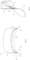
- Other conformations of the winglet 32 are shown in figures 3 and 8 .
- the axial extension upstream of the winglet 32 is greater and is wider in the tangential direction (i.e. along the chord of the blade 24 airfoil).
- this type of winglet 32 with greater axial extension allows for greater engagement of the annular seat 30.
- the duct 26 of the fan 20 comprises a converging mouth 38.
- the converging mouth 38 is defined at the upstream end of the duct 26 and serves the function of receiving the air flow into the intake zone and gently conveying it to the rotor 22.
- the converging mouth 38 is defined in a per se known manner by the wall of the duct 26 itself.
- the converging mouth 38 is defined by an upstream protrusion of the aerodynamic smoothing surface 36, in particular of the converging aerodynamic smoothing surface 36c.
- the duct 26 has a circular cylindrical shape in the axial segment comprising the rotor 22 and has an inner diameter Dd slightly greater than the outer diameter Dr of the rotor 22.
- the annular seat 30 is thus obtained from a traditional duct 26 by adding an aerodynamic smoothing surface 36.
- a converging aerodynamic smoothing surface 36c is arranged, immediately upstream of the rotor 22.
- the converging aerodynamic smoothing surface 36c thus causes a narrowing in the channel 28 included in the duct 26, such that the inner diameter Ds of the annular seat 30 is slightly smaller than the outer diameter Dr of the rotor 22.
- Due to the shape of the converging aerodynamic smoothing surface 36c the annular seat 30 is axially open downstream.
- the blade 24 includes a tip winglet 32 with a baffle 34 axially extending upstream and being received in the annular seat 30.
- the duct 26 has a circular cylindrical shape and in the segment immediately upstream of the rotor 22 has an inner diameter slightly smaller than the outer diameter Dr of the rotor 22. In this case, upstream of the rotor 22, the inner diameter of the duct 26 coincides with the inner diameter Ds of the annular seat 30.
- the duct 26 stops near the rotor 22, where the annular seat 30 is arranged, and continues in correspondence and downstream of the rotor 22 with an inner diameter Dd slightly greater than the outer diameter Dr of the rotor 22. Due to the shape of the duct 26, the annular seat 30 is axially open downstream.
- the blade 24 includes a tip winglet 32 with a baffle 34 axially extending upstream and being received in the annular seat 30.
- FIG.c The embodiment schematically shown in figure 4.c is very similar to that of figure 4.a , to the description of which reference is made.
- a diverging aerodynamic smoothing surface 36d is arranged, immediately downstream of the rotor 22.
- the resulting annular seat 30 develops overall within the channel 28 of the duct 26.
- Such annular seat 30 is open in the radial direction towards the inside and extends in the axial direction downstream and upstream.
- the blade 24 includes a tip winglet 32 with a baffle 34. The tip of the blade 24 is radially received in the annular seat 30 and the baffle 34 of the winglet 32 axially extends downstream and upstream inside the annular seat 30.
- the duct 26 has a circular cylindrical shape in the axial segment comprising the rotor 22 and has an inner diameter Dd slightly greater than the outer diameter Dr of the rotor 22.
- the annular seat 30 is thus obtained from a traditional duct 26 by adding an aerodynamic smoothing surface 36.
- a diverging aerodynamic smoothing surface 36d is arranged, immediately downstream of the rotor 22.
- the diverging aerodynamic smoothing surface 36d thus determines a narrowing in the channel 28 included in the duct 26, such that the inner diameter Ds of the annular seat 30 is slightly smaller than the outer diameter Dr of the rotor 22. Due to the shape of the diverging aerodynamic smoothing surface 36d, the annular seat 30 is axially open upstream.
- the blade 24 includes a tip winglet 32 with a baffle 34 axially extending downstream and being received in the annular seat 30.
- the duct 26 has a circular cylindrical shape and in the segment immediately upstream and immediately downstream of the rotor 22 has an inner diameter slightly smaller than the outer diameter Dr of the rotor 22.
- the inner diameter of the duct 26 coincides with the inner diameter Ds of the annular seat 30.
- the duct 26 is then interrupted near the rotor 22, where the annular seat 30 is arranged.
- the resulting annular seat 30 develops overall outside the channel 28 of the duct 26.
- Such annular seat 30 is open in the radial direction towards the inside and extends in the axial direction downstream and upstream.
- the blade 24 includes a tip winglet 32 with a baffle 34. The tip of the blade 24 is radially received in the annular seat 30 and the baffle 34 of the winglet 32 axially extends downstream and upstream inside the annular seat 30.
- the duct 26 assumes a shape similar to that obtained by reversing the duct 26 of figure 4.b .
- the duct 26 has a circular cylindrical shape and in the segment immediately upstream of the rotor 22 and in correspondence of the rotor 22, where the annular seat 30 is arranged, has an inner diameter Dd slightly greater than the outer diameter Dr of the rotor 22.
- the duct 26 continues downstream of the rotor 22 with an inner diameter slightly smaller than the outer diameter of the rotor 22. In this case, downstream of the rotor 22, the inner diameter of the duct 26 coincides with the inner diameter Ds of the annular seat 30. Due to the shape of the duct 26, the annular seat 30 is axially open upstream.
- the blade 24 includes a tip winglet 32 with a baffle 34 axially extending downstream and being received in the annular seat 30.
- FIG.g The embodiment schematically shown in figure 4.g is very similar to that of figure 4.f , to the description of which reference is made.
- a converging aerodynamic smoothing surface 36c is arranged, immediately upstream of the rotor 22.
- the resulting annular seat 30 is open in the radial direction towards the inside and extends in the axial direction downstream and upstream.
- the blade 24 includes a tip winglet 32 with a baffle 34. The tip of the blade 24 is radially received in the annular seat 30 and the baffle 34 of the winglet 32 axially extends downstream and upstream inside the annular seat 30.
- FIG.h The embodiment schematically shown in figure 4.h is very similar to that of figure 4.b , to the description of which reference is made.
- a diverging aerodynamic smoothing surface 36d is arranged, immediately downstream of the rotor 22.
- the resulting annular seat 30 is open in the radial direction towards the inside and extends in the axial direction downstream and upstream.
- the blade 24 includes a tip winglet 32 with a baffle 34. The tip of the blade 24 is radially received in the annular seat 30 and the baffle 34 of the winglet 32 axially extends downstream and upstream inside the annular seat 30.
- FIG 4.i The embodiment schematically shown in figure 4.i is very similar to that of figure 4.c , to the description of which reference is made.
- the blade 24 does not comprise any tip winglet 32 and is thus not a part of the claimed invention.
- the tip of the blade 24 is radially received in the annular seat 30.
- figure 4.j The embodiment schematically shown in figure 4.j is very similar to that of figure 4.e , to the description of which reference is made.
- the blade 24 does not comprise any tip winglet 32 and is thus not a part of the claimed invention.
- the tip of the blade 24 is radially received in the annular seat 30.
- the duct 26 has a circular cylindrical shape in the axial segment comprising the rotor 22 and has an inner diameter Dd slightly greater than the outer diameter Dr of the rotor 22.
- the annular seat 30 is thus obtained from a traditional duct 26 by adding an aerodynamic smoothing surface 36.
- a converging aerodynamic smoothing surface 36c is arranged, immediately upstream of the rotor 22.
- the aerodynamic smoothing surface protrudes upstream to form the converging mouth 38.
- the converging aerodynamic smoothing surface 36c causes a narrowing in the channel 28, the inner diameter Ds of the annular seat 30 is slightly smaller than the outer diameter Dr of the rotor 22, the annular seat 30 is axially open downstream.
- the blade 24 includes a tip winglet 32 with a baffle 34 axially extending upstream and being received in the annular seat 30.
- the embodiment schematically shown in figure 4.l is similar to that of figure 4.e , to the description of which reference is made. In this embodiment, however, the duct 26 wall is shaped so as to form, upstream of the rotor 22, the converging mouth 38.
- the converging aerodynamic smoothing surface 36c is not shaped so as to define a soft and continuous narrowing in the channel 28, but is shaped with a sharp-cornered profile that introduces an abrupt step narrowing.
- annular seat 30 The configurations of the duct 26 and annular seat 30 described above with reference to figures 4 are shown by way of example. As it will be well understood by the skilled person, the annular seat 30 can take different shapes from those described herein in detail, in order to meet specific needs.
- a labyrinth seal defines a tortuous path that significantly reduces the spontaneous passage of a fluid from a high-pressure zone to a low-pressure zone.
- the configuration of the annular seat 30 and of the tip of the blade 24 define a tortuous path for air that spontaneously tends to flow from the high-pressure zone (above the blade 24) to the low-pressure zone (below the blade 24).
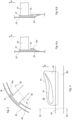
- figures 5 to 11 are similar to that schematized in figure 4.a . More particularly, figures 5 and 6 represent one embodiment of the rotor 22, while figures 7 , 8, and 9 represent a different embodiment of the rotor 22. The main difference between the two embodiments consists in the shape and extension of the baffle 34 of the winglet 32. Figure 6 shows a winglet 32 smaller than that seen in figure 8 .
- the duct 26 and annular seat 30 are common to both embodiments and are depicted in more detail in figures 10 and 11 .
- the duct 26 has a circular cylindrical shape in the axial segment comprising the rotor 22 and has an inner diameter Dd slightly larger than the outer diameter Dr of the rotor 22 (see figure 9 ).
- the annular seat 30 is thus obtained from a traditional duct 26 by adding the aerodynamic smoothing surface 36.
- the converging aerodynamic smoothing surface 36c is arranged, immediately upstream of the rotor 22.
- the converging aerodynamic smoothing surface 36c thus determines a narrowing in the channel 28 included in the duct 26, such that the inner diameter Ds of the annular seat 30 is slightly smaller than the outer diameter Dr of the rotor 22 (see again figure 9 ).
- the annular seat 30 is axially open downstream.
- the blades 24 comprise respective tip winglets 32 that take different shapes, but in any case they have a baffle 34 axially extending upstream and being received in the annular seat 30.
- Embodiments comprising a traditional duct 26 to which aerodynamic smoothing surfaces 36 are added allow an existing fan 20 to be modified in order to be in accordance with the invention.
- Such embodiments are shown in figures 4.a , 4.c , 4.d , 4.i , 4.k, 4.m and 4.n , for example.
- Embodiments including a narrowing of the channel 28 at the annular seat 30, allow for local acceleration of the air flow.
- the difference between the inner diameter Dd of the duct 26 and the inner diameter Ds of the seat may in some cases reach up to 5% of the inner diameter Dd of the duct 26. In most cases, however, this difference is less than 2% of Dd. Since this reduction is located precisely at the radial periphery, where the flow speed is greater, the local effect of the narrowing on the flow speed is even more evident.
- Such embodiments are shown in figures 4.a , 4.c, 4.d, 4.f , 4.g, 4.i , 4.m and 4.n , for example.
- Embodiments comprising an enlargement of the channel 28 at the annular seat 30, allow for optimal arrangement of the air flow for applications requiring a diverging outlet at the discharge of the entire duct 26.
- Such embodiments are shown in figures 4.b , 4.h and 4.k , for example.
- the fan 20 according to the invention also comprises a motor (not shown) suitable for rotating the rotor 22 at the design speed.
- the fan 20 according to the invention preferably comprises a structure (not shown) suitable for firmly supporting the duct 26, the rotor 22 and possibly the motor in all operating conditions.
- the rotor 22 is of the variable pitch type.
- each individual blade 24 may be rotated about an axis p having substantially radial direction.
- the possibility of simultaneously rotating each blade 24 about the respective axis p allows to modify its incidence with respect to the air (see figures 15 ), thus varying the flow rate of the ducted fan 20 itself.
- the variable pitch ducted fans 20 thus allow to adapt to different operating conditions and are therefore widely used in various fields.
- variable pitch ducted fans 20 A field in which variable pitch ducted fans 20 are particularly appreciated is the aeronautical field.
- Various types of aircraft employ variable pitch ducted fans 20, for example for aircraft propulsion and/or control.
- variable pitch ducted fan 20 is the ducted tail rotor of a helicopter 40 (see by way of example figure 12 ).
- This solution also commonly called fenestron, although widely appreciated, has the same drawbacks already identified above for ducted fans for industrial use.
- annular seat 30 circumferentially extending around the rotor 22, wherein the tips of the blades 24 are at least partially received in the annular seat 30.
- the invention allows to overcome the drawbacks previously highlighted with reference to the prior art.
- the present invention provides a ducted axial fan which has an improved efficiency.
- the present invention provides a ducted axial fan which limits the formation of tip vortexes more than known type fans.
- the present invention provides a ducted axial fan which, in addition to introducing further advantages, also maintains the advantages already obtained by known type fans.
Landscapes
- Engineering & Computer Science (AREA)
- Mechanical Engineering (AREA)
- General Engineering & Computer Science (AREA)
- Aviation & Aerospace Engineering (AREA)
- Physics & Mathematics (AREA)
- Fluid Mechanics (AREA)
- Structures Of Non-Positive Displacement Pumps (AREA)
- Motor Or Generator Cooling System (AREA)
Applications Claiming Priority (2)
| Application Number | Priority Date | Filing Date | Title |
|---|---|---|---|
| IT102019000007935A IT201900007935A1 (it) | 2019-06-04 | 2019-06-04 | Ventilatore con virola migliorata |
| PCT/IB2020/054312 WO2020245674A1 (en) | 2019-06-04 | 2020-05-07 | Fan with improved duct |
Publications (2)
| Publication Number | Publication Date |
|---|---|
| EP3980649A1 EP3980649A1 (en) | 2022-04-13 |
| EP3980649B1 true EP3980649B1 (en) | 2023-11-08 |
Family
ID=67998681
Family Applications (1)
| Application Number | Title | Priority Date | Filing Date |
|---|---|---|---|
| EP20728198.1A Active EP3980649B1 (en) | 2019-06-04 | 2020-05-07 | Fan with improved duct |
Country Status (18)
| Country | Link |
|---|---|
| US (1) | US11802572B2 (https=) |
| EP (1) | EP3980649B1 (https=) |
| JP (1) | JP7504481B2 (https=) |
| KR (1) | KR102842627B1 (https=) |
| CN (1) | CN114245848B (https=) |
| AU (1) | AU2020288384B2 (https=) |
| CO (1) | CO2021016474A2 (https=) |
| ES (1) | ES2968818T3 (https=) |
| FI (1) | FI3980649T3 (https=) |
| IL (1) | IL288614B2 (https=) |
| IT (1) | IT201900007935A1 (https=) |
| MA (1) | MA56094A (https=) |
| MX (1) | MX2021014967A (https=) |
| PH (1) | PH12021553031A1 (https=) |
| PL (1) | PL3980649T3 (https=) |
| SA (1) | SA521431006B1 (https=) |
| UA (1) | UA128929C2 (https=) |
| WO (1) | WO2020245674A1 (https=) |
Families Citing this family (5)
| Publication number | Priority date | Publication date | Assignee | Title |
|---|---|---|---|---|
| US12071228B1 (en) * | 2019-03-28 | 2024-08-27 | Snap Inc. | Drone with propeller guard configured as an airfoil |
| US11286955B2 (en) * | 2019-10-11 | 2022-03-29 | General Electric Company | Ducted fan with fan casing defining an over-rotor cavity |
| IT202100014219A1 (it) | 2021-05-31 | 2022-12-01 | R E M Holding S R L | Rotore e ventilatore assiale comprendenti una ventola accessoria |
| IT202300006966A1 (it) | 2023-04-11 | 2024-10-11 | R E M Patents S R L | Ventilatore assiale comprendente una paratia all’estremità delle pale |
| WO2025220915A1 (ko) * | 2024-04-16 | 2025-10-23 | 주식회사 메트로에어 | 수직 이착륙 비행 장치, 이의 기동 방법 및 조정 장치 |
Family Cites Families (14)
| Publication number | Priority date | Publication date | Assignee | Title |
|---|---|---|---|---|
| US2609053A (en) * | 1946-10-31 | 1952-09-02 | United Aircraft Corp | Shrouded tail rotor |
| FR2719551B1 (fr) * | 1994-05-04 | 1996-07-12 | Eurocopter France | Dispositif anti-couple à rotor et stator redresseur carénés, et à aubes redresseuses inclinées. |
| US6024537A (en) * | 1997-07-29 | 2000-02-15 | Valeo Engine Cooling, Inc. | Axial flow fan |
| US6338609B1 (en) * | 2000-02-18 | 2002-01-15 | General Electric Company | Convex compressor casing |
| KR100848569B1 (ko) * | 2002-07-15 | 2008-07-25 | 한라공조주식회사 | 팬 쉬라우드 |
| RU2232103C1 (ru) | 2002-12-30 | 2004-07-10 | Открытое Акционерное Общество "Московский Вертолетный Завод Им. М.Л.Миля" | Боевой вертолет |
| JP4085948B2 (ja) * | 2003-10-01 | 2008-05-14 | 株式会社デンソー | 冷却ファンおよび送風機 |
| US20100040458A1 (en) * | 2006-12-28 | 2010-02-18 | Carrier Corporation | Axial fan casing design with circumferentially spaced wedges |
| US8568095B2 (en) * | 2006-12-29 | 2013-10-29 | Carrier Corporation | Reduced tip clearance losses in axial flow fans |
| FR2999151B1 (fr) | 2012-12-07 | 2017-01-27 | Snecma | Pale d'helice pour turbomachine |
| DE102014111767A1 (de) * | 2014-08-18 | 2016-02-18 | Ebm-Papst Mulfingen Gmbh & Co. Kg | Axialventilator |
| FR3034145B1 (fr) * | 2015-03-26 | 2017-04-07 | Snecma | Etage de compresseur |
| CN109334952A (zh) * | 2018-11-26 | 2019-02-15 | 南京航空航天大学 | 一种基于嵌入式涵道螺旋桨驱动的新型桨叶 |
| DE102019220232B4 (de) * | 2019-12-19 | 2026-01-08 | Brose Fahrzeugteile SE & Co. Kommanditgesellschaft, Würzburg | Kühlerlüfter |
-
2019
- 2019-06-04 IT IT102019000007935A patent/IT201900007935A1/it unknown
-
2020
- 2020-05-07 JP JP2021571695A patent/JP7504481B2/ja active Active
- 2020-05-07 PL PL20728198.1T patent/PL3980649T3/pl unknown
- 2020-05-07 KR KR1020217041719A patent/KR102842627B1/ko active Active
- 2020-05-07 IL IL288614A patent/IL288614B2/en unknown
- 2020-05-07 AU AU2020288384A patent/AU2020288384B2/en active Active
- 2020-05-07 UA UAA202106661A patent/UA128929C2/uk unknown
- 2020-05-07 MX MX2021014967A patent/MX2021014967A/es unknown
- 2020-05-07 US US17/616,570 patent/US11802572B2/en active Active
- 2020-05-07 FI FIEP20728198.1T patent/FI3980649T3/fi active
- 2020-05-07 WO PCT/IB2020/054312 patent/WO2020245674A1/en not_active Ceased
- 2020-05-07 CN CN202080055464.6A patent/CN114245848B/zh active Active
- 2020-05-07 MA MA056094A patent/MA56094A/fr unknown
- 2020-05-07 PH PH1/2021/553031A patent/PH12021553031A1/en unknown
- 2020-05-07 EP EP20728198.1A patent/EP3980649B1/en active Active
- 2020-05-07 ES ES20728198T patent/ES2968818T3/es active Active
-
2021
- 2021-12-01 SA SA521431006A patent/SA521431006B1/ar unknown
- 2021-12-02 CO CONC2021/0016474A patent/CO2021016474A2/es unknown
Also Published As
| Publication number | Publication date |
|---|---|
| PL3980649T3 (pl) | 2024-05-06 |
| CO2021016474A2 (es) | 2022-01-17 |
| US20220252080A1 (en) | 2022-08-11 |
| IL288614B2 (en) | 2025-04-01 |
| AU2020288384B2 (en) | 2025-06-26 |
| CN114245848A (zh) | 2022-03-25 |
| BR112021024479A2 (pt) | 2022-01-18 |
| WO2020245674A1 (en) | 2020-12-10 |
| UA128929C2 (uk) | 2024-11-27 |
| IT201900007935A1 (it) | 2020-12-04 |
| EP3980649A1 (en) | 2022-04-13 |
| SA521431006B1 (ar) | 2024-07-31 |
| MX2021014967A (es) | 2022-04-06 |
| IL288614A (en) | 2022-02-01 |
| AU2020288384A1 (en) | 2022-01-20 |
| KR102842627B1 (ko) | 2025-08-05 |
| JP7504481B2 (ja) | 2024-06-24 |
| KR20220016878A (ko) | 2022-02-10 |
| FI3980649T3 (fi) | 2024-01-12 |
| US11802572B2 (en) | 2023-10-31 |
| ES2968818T3 (es) | 2024-05-14 |
| CN114245848B (zh) | 2024-05-17 |
| MA56094A (fr) | 2022-04-13 |
| CA3142393A1 (en) | 2020-12-10 |
| JP2022535821A (ja) | 2022-08-10 |
| IL288614B1 (en) | 2024-12-01 |
| PH12021553031A1 (en) | 2023-08-23 |
Similar Documents
| Publication | Publication Date | Title |
|---|---|---|
| EP3980649B1 (en) | Fan with improved duct | |
| CA3045693C (en) | Aft engine nacelle shape for an aircraft | |
| CA2941825C (en) | Non-axis symmetric aft engine | |
| CA2941828C (en) | Aircraft having an aft engine | |
| US10704418B2 (en) | Inlet assembly for an aircraft aft fan | |
| NL7908792A (nl) | Rotor voor toepassing in een stromingsmedium. | |
| JP2012031864A (ja) | 低圧蒸気タービン及び低圧蒸気タービンを運転する方法 | |
| EP3942186B1 (en) | Axial fan with trailing edge flap | |
| CA3142393C (en) | Fan with improved duct | |
| HK40064371B (en) | Fan with improved duct | |
| HK40064371A (en) | Fan with improved duct | |
| RU2811874C2 (ru) | Вентилятор с усовершенствованным каналом | |
| BR112021024479B1 (pt) | Hélice axial canalizada | |
| HK40060163B (zh) | 具有後缘襟翼的轴流式风机 |
Legal Events
| Date | Code | Title | Description |
|---|---|---|---|
| STAA | Information on the status of an ep patent application or granted ep patent |
Free format text: STATUS: UNKNOWN |
|
| STAA | Information on the status of an ep patent application or granted ep patent |
Free format text: STATUS: THE INTERNATIONAL PUBLICATION HAS BEEN MADE |
|
| PUAI | Public reference made under article 153(3) epc to a published international application that has entered the european phase |
Free format text: ORIGINAL CODE: 0009012 |
|
| STAA | Information on the status of an ep patent application or granted ep patent |
Free format text: STATUS: REQUEST FOR EXAMINATION WAS MADE |
|
| 17P | Request for examination filed |
Effective date: 20211122 |
|
| AK | Designated contracting states |
Kind code of ref document: A1 Designated state(s): AL AT BE BG CH CY CZ DE DK EE ES FI FR GB GR HR HU IE IS IT LI LT LU LV MC MK MT NL NO PL PT RO RS SE SI SK SM TR |
|
| REG | Reference to a national code |
Ref country code: HK Ref legal event code: DE Ref document number: 40064371 Country of ref document: HK |
|
| DAX | Request for extension of the european patent (deleted) | ||
| RAV | Requested validation state of the european patent: fee paid |
Extension state: TN Effective date: 20211122 Extension state: MA Effective date: 20211122 |
|
| GRAP | Despatch of communication of intention to grant a patent |
Free format text: ORIGINAL CODE: EPIDOSNIGR1 |
|
| STAA | Information on the status of an ep patent application or granted ep patent |
Free format text: STATUS: GRANT OF PATENT IS INTENDED |
|
| INTG | Intention to grant announced |
Effective date: 20230612 |
|
| P01 | Opt-out of the competence of the unified patent court (upc) registered |
Effective date: 20230530 |
|
| GRAS | Grant fee paid |
Free format text: ORIGINAL CODE: EPIDOSNIGR3 |
|
| GRAA | (expected) grant |
Free format text: ORIGINAL CODE: 0009210 |
|
| STAA | Information on the status of an ep patent application or granted ep patent |
Free format text: STATUS: THE PATENT HAS BEEN GRANTED |
|
| AK | Designated contracting states |
Kind code of ref document: B1 Designated state(s): AL AT BE BG CH CY CZ DE DK EE ES FI FR GB GR HR HU IE IS IT LI LT LU LV MC MK MT NL NO PL PT RO RS SE SI SK SM TR |
|
| REG | Reference to a national code |
Ref country code: GB Ref legal event code: FG4D |
|
| REG | Reference to a national code |
Ref country code: CH Ref legal event code: EP |
|
| REG | Reference to a national code |
Ref country code: DE Ref legal event code: R096 Ref document number: 602020020706 Country of ref document: DE |
|
| REG | Reference to a national code |
Ref country code: IE Ref legal event code: FG4D |
|
| REG | Reference to a national code |
Ref country code: FI Ref legal event code: FGE |
|
| RAP2 | Party data changed (patent owner data changed or rights of a patent transferred) |
Owner name: R.E.M. PATENTS S.R.L. |
|
| REG | Reference to a national code |
Ref country code: NL Ref legal event code: PD Owner name: R.E.M. PATENTS S.R.L.; IT Free format text: DETAILS ASSIGNMENT: CHANGE OF OWNER(S), ASSIGNMENT; FORMER OWNER NAME: R.E.M. HOLDING S.R.L. Effective date: 20240108 Ref country code: NL Ref legal event code: FP |
|
| REG | Reference to a national code |
Ref country code: DE Ref legal event code: R081 Ref document number: 602020020706 Country of ref document: DE Owner name: R.E.M. PATENTS S.R.L., IT Free format text: FORMER OWNER: R.E.M. HOLDING S.R.L., MILANO, IT |
|
| REG | Reference to a national code |
Ref country code: LT Ref legal event code: MG9D |
|
| REG | Reference to a national code |
Ref country code: GB Ref legal event code: 732E Free format text: REGISTERED BETWEEN 20240201 AND 20240207 |
|
| PG25 | Lapsed in a contracting state [announced via postgrant information from national office to epo] |
Ref country code: GR Free format text: LAPSE BECAUSE OF FAILURE TO SUBMIT A TRANSLATION OF THE DESCRIPTION OR TO PAY THE FEE WITHIN THE PRESCRIBED TIME-LIMIT Effective date: 20240209 |
|
| PG25 | Lapsed in a contracting state [announced via postgrant information from national office to epo] |
Ref country code: IS Free format text: LAPSE BECAUSE OF FAILURE TO SUBMIT A TRANSLATION OF THE DESCRIPTION OR TO PAY THE FEE WITHIN THE PRESCRIBED TIME-LIMIT Effective date: 20240308 |
|
| PG25 | Lapsed in a contracting state [announced via postgrant information from national office to epo] |
Ref country code: LT Free format text: LAPSE BECAUSE OF FAILURE TO SUBMIT A TRANSLATION OF THE DESCRIPTION OR TO PAY THE FEE WITHIN THE PRESCRIBED TIME-LIMIT Effective date: 20231108 |
|
| REG | Reference to a national code |
Ref country code: AT Ref legal event code: MK05 Ref document number: 1629835 Country of ref document: AT Kind code of ref document: T Effective date: 20231108 |
|
| PG25 | Lapsed in a contracting state [announced via postgrant information from national office to epo] |
Ref country code: AT Free format text: LAPSE BECAUSE OF FAILURE TO SUBMIT A TRANSLATION OF THE DESCRIPTION OR TO PAY THE FEE WITHIN THE PRESCRIBED TIME-LIMIT Effective date: 20231108 |
|
| PG25 | Lapsed in a contracting state [announced via postgrant information from national office to epo] |
Ref country code: LT Free format text: LAPSE BECAUSE OF FAILURE TO SUBMIT A TRANSLATION OF THE DESCRIPTION OR TO PAY THE FEE WITHIN THE PRESCRIBED TIME-LIMIT Effective date: 20231108 Ref country code: IS Free format text: LAPSE BECAUSE OF FAILURE TO SUBMIT A TRANSLATION OF THE DESCRIPTION OR TO PAY THE FEE WITHIN THE PRESCRIBED TIME-LIMIT Effective date: 20240308 Ref country code: GR Free format text: LAPSE BECAUSE OF FAILURE TO SUBMIT A TRANSLATION OF THE DESCRIPTION OR TO PAY THE FEE WITHIN THE PRESCRIBED TIME-LIMIT Effective date: 20240209 Ref country code: BG Free format text: LAPSE BECAUSE OF FAILURE TO SUBMIT A TRANSLATION OF THE DESCRIPTION OR TO PAY THE FEE WITHIN THE PRESCRIBED TIME-LIMIT Effective date: 20240208 Ref country code: AT Free format text: LAPSE BECAUSE OF FAILURE TO SUBMIT A TRANSLATION OF THE DESCRIPTION OR TO PAY THE FEE WITHIN THE PRESCRIBED TIME-LIMIT Effective date: 20231108 Ref country code: PT Free format text: LAPSE BECAUSE OF FAILURE TO SUBMIT A TRANSLATION OF THE DESCRIPTION OR TO PAY THE FEE WITHIN THE PRESCRIBED TIME-LIMIT Effective date: 20240308 |
|
| REG | Reference to a national code |
Ref country code: ES Ref legal event code: FG2A Ref document number: 2968818 Country of ref document: ES Kind code of ref document: T3 Effective date: 20240514 |
|
| PG25 | Lapsed in a contracting state [announced via postgrant information from national office to epo] |
Ref country code: SE Free format text: LAPSE BECAUSE OF FAILURE TO SUBMIT A TRANSLATION OF THE DESCRIPTION OR TO PAY THE FEE WITHIN THE PRESCRIBED TIME-LIMIT Effective date: 20231108 Ref country code: RS Free format text: LAPSE BECAUSE OF FAILURE TO SUBMIT A TRANSLATION OF THE DESCRIPTION OR TO PAY THE FEE WITHIN THE PRESCRIBED TIME-LIMIT Effective date: 20231108 Ref country code: NO Free format text: LAPSE BECAUSE OF FAILURE TO SUBMIT A TRANSLATION OF THE DESCRIPTION OR TO PAY THE FEE WITHIN THE PRESCRIBED TIME-LIMIT Effective date: 20240208 Ref country code: LV Free format text: LAPSE BECAUSE OF FAILURE TO SUBMIT A TRANSLATION OF THE DESCRIPTION OR TO PAY THE FEE WITHIN THE PRESCRIBED TIME-LIMIT Effective date: 20231108 Ref country code: HR Free format text: LAPSE BECAUSE OF FAILURE TO SUBMIT A TRANSLATION OF THE DESCRIPTION OR TO PAY THE FEE WITHIN THE PRESCRIBED TIME-LIMIT Effective date: 20231108 |
|
| PG25 | Lapsed in a contracting state [announced via postgrant information from national office to epo] |
Ref country code: DK Free format text: LAPSE BECAUSE OF FAILURE TO SUBMIT A TRANSLATION OF THE DESCRIPTION OR TO PAY THE FEE WITHIN THE PRESCRIBED TIME-LIMIT Effective date: 20231108 |
|
| PG25 | Lapsed in a contracting state [announced via postgrant information from national office to epo] |
Ref country code: CZ Free format text: LAPSE BECAUSE OF FAILURE TO SUBMIT A TRANSLATION OF THE DESCRIPTION OR TO PAY THE FEE WITHIN THE PRESCRIBED TIME-LIMIT Effective date: 20231108 |
|
| PG25 | Lapsed in a contracting state [announced via postgrant information from national office to epo] |
Ref country code: SK Free format text: LAPSE BECAUSE OF FAILURE TO SUBMIT A TRANSLATION OF THE DESCRIPTION OR TO PAY THE FEE WITHIN THE PRESCRIBED TIME-LIMIT Effective date: 20231108 |
|
| PG25 | Lapsed in a contracting state [announced via postgrant information from national office to epo] |
Ref country code: SM Free format text: LAPSE BECAUSE OF FAILURE TO SUBMIT A TRANSLATION OF THE DESCRIPTION OR TO PAY THE FEE WITHIN THE PRESCRIBED TIME-LIMIT Effective date: 20231108 Ref country code: SK Free format text: LAPSE BECAUSE OF FAILURE TO SUBMIT A TRANSLATION OF THE DESCRIPTION OR TO PAY THE FEE WITHIN THE PRESCRIBED TIME-LIMIT Effective date: 20231108 Ref country code: RO Free format text: LAPSE BECAUSE OF FAILURE TO SUBMIT A TRANSLATION OF THE DESCRIPTION OR TO PAY THE FEE WITHIN THE PRESCRIBED TIME-LIMIT Effective date: 20231108 Ref country code: EE Free format text: LAPSE BECAUSE OF FAILURE TO SUBMIT A TRANSLATION OF THE DESCRIPTION OR TO PAY THE FEE WITHIN THE PRESCRIBED TIME-LIMIT Effective date: 20231108 Ref country code: DK Free format text: LAPSE BECAUSE OF FAILURE TO SUBMIT A TRANSLATION OF THE DESCRIPTION OR TO PAY THE FEE WITHIN THE PRESCRIBED TIME-LIMIT Effective date: 20231108 Ref country code: CZ Free format text: LAPSE BECAUSE OF FAILURE TO SUBMIT A TRANSLATION OF THE DESCRIPTION OR TO PAY THE FEE WITHIN THE PRESCRIBED TIME-LIMIT Effective date: 20231108 |
|
| REG | Reference to a national code |
Ref country code: DE Ref legal event code: R097 Ref document number: 602020020706 Country of ref document: DE |
|
| PLBE | No opposition filed within time limit |
Free format text: ORIGINAL CODE: 0009261 |
|
| STAA | Information on the status of an ep patent application or granted ep patent |
Free format text: STATUS: NO OPPOSITION FILED WITHIN TIME LIMIT |
|
| REG | Reference to a national code |
Ref country code: HK Ref legal event code: CORR Ref document number: 40064371 Country of ref document: HK Free format text: HONG KONG INTELLECTUAL PROPERTY JOURNAL: CORRECTED DATA OF SECTION 27 17.05.2024: (73) R.E.M. PATENTS S.R.L., 28041 ARONA (NO) ITALY |
|
| 26N | No opposition filed |
Effective date: 20240809 |
|
| PG25 | Lapsed in a contracting state [announced via postgrant information from national office to epo] |
Ref country code: SI Free format text: LAPSE BECAUSE OF FAILURE TO SUBMIT A TRANSLATION OF THE DESCRIPTION OR TO PAY THE FEE WITHIN THE PRESCRIBED TIME-LIMIT Effective date: 20231108 |
|
| PG25 | Lapsed in a contracting state [announced via postgrant information from national office to epo] |
Ref country code: SI Free format text: LAPSE BECAUSE OF FAILURE TO SUBMIT A TRANSLATION OF THE DESCRIPTION OR TO PAY THE FEE WITHIN THE PRESCRIBED TIME-LIMIT Effective date: 20231108 |
|
| REG | Reference to a national code |
Ref country code: CH Ref legal event code: PL |
|
| PG25 | Lapsed in a contracting state [announced via postgrant information from national office to epo] |
Ref country code: MC Free format text: LAPSE BECAUSE OF FAILURE TO SUBMIT A TRANSLATION OF THE DESCRIPTION OR TO PAY THE FEE WITHIN THE PRESCRIBED TIME-LIMIT Effective date: 20231108 |
|
| PG25 | Lapsed in a contracting state [announced via postgrant information from national office to epo] |
Ref country code: LU Free format text: LAPSE BECAUSE OF NON-PAYMENT OF DUE FEES Effective date: 20240507 |
|
| PG25 | Lapsed in a contracting state [announced via postgrant information from national office to epo] |
Ref country code: MC Free format text: LAPSE BECAUSE OF FAILURE TO SUBMIT A TRANSLATION OF THE DESCRIPTION OR TO PAY THE FEE WITHIN THE PRESCRIBED TIME-LIMIT Effective date: 20231108 Ref country code: LU Free format text: LAPSE BECAUSE OF NON-PAYMENT OF DUE FEES Effective date: 20240507 Ref country code: CH Free format text: LAPSE BECAUSE OF NON-PAYMENT OF DUE FEES Effective date: 20240531 |
|
| REG | Reference to a national code |
Ref country code: BE Ref legal event code: MM Effective date: 20240531 |
|
| PG25 | Lapsed in a contracting state [announced via postgrant information from national office to epo] |
Ref country code: IE Free format text: LAPSE BECAUSE OF NON-PAYMENT OF DUE FEES Effective date: 20240507 |
|
| PG25 | Lapsed in a contracting state [announced via postgrant information from national office to epo] |
Ref country code: BE Free format text: LAPSE BECAUSE OF NON-PAYMENT OF DUE FEES Effective date: 20240531 |
|
| PGFP | Annual fee paid to national office [announced via postgrant information from national office to epo] |
Ref country code: NL Payment date: 20250523 Year of fee payment: 6 |
|
| PGFP | Annual fee paid to national office [announced via postgrant information from national office to epo] |
Ref country code: FI Payment date: 20250523 Year of fee payment: 6 |
|
| PGFP | Annual fee paid to national office [announced via postgrant information from national office to epo] |
Ref country code: PL Payment date: 20250429 Year of fee payment: 6 Ref country code: DE Payment date: 20250602 Year of fee payment: 6 |
|
| PGFP | Annual fee paid to national office [announced via postgrant information from national office to epo] |
Ref country code: GB Payment date: 20250524 Year of fee payment: 6 Ref country code: ES Payment date: 20250602 Year of fee payment: 6 |
|
| PGFP | Annual fee paid to national office [announced via postgrant information from national office to epo] |
Ref country code: IT Payment date: 20250529 Year of fee payment: 6 |
|
| PGFP | Annual fee paid to national office [announced via postgrant information from national office to epo] |
Ref country code: FR Payment date: 20250520 Year of fee payment: 6 |
|
| PGFP | Annual fee paid to national office [announced via postgrant information from national office to epo] |
Ref country code: TR Payment date: 20250430 Year of fee payment: 6 |
|
| PG25 | Lapsed in a contracting state [announced via postgrant information from national office to epo] |
Ref country code: CY Free format text: LAPSE BECAUSE OF FAILURE TO SUBMIT A TRANSLATION OF THE DESCRIPTION OR TO PAY THE FEE WITHIN THE PRESCRIBED TIME-LIMIT; INVALID AB INITIO Effective date: 20200507 |
|
| PG25 | Lapsed in a contracting state [announced via postgrant information from national office to epo] |
Ref country code: HU Free format text: LAPSE BECAUSE OF FAILURE TO SUBMIT A TRANSLATION OF THE DESCRIPTION OR TO PAY THE FEE WITHIN THE PRESCRIBED TIME-LIMIT; INVALID AB INITIO Effective date: 20200507 |
|
| VS25 | Lapsed in a validation state [announced via postgrant information from nat. office to epo] |
Ref country code: MA Free format text: FAILURE TO ELECT DOMICILE IN THE NATIONAL COUNTRY Effective date: 20240209 |