EP3979926B1 - Rotierendes chirurgisches schneidwerkzeug und relevantes zubehör - Google Patents
Rotierendes chirurgisches schneidwerkzeug und relevantes zubehör Download PDFInfo
- Publication number
- EP3979926B1 EP3979926B1 EP20732669.5A EP20732669A EP3979926B1 EP 3979926 B1 EP3979926 B1 EP 3979926B1 EP 20732669 A EP20732669 A EP 20732669A EP 3979926 B1 EP3979926 B1 EP 3979926B1
- Authority
- EP
- European Patent Office
- Prior art keywords
- nose tube
- driveshaft
- proximal
- assembly
- hub
- Prior art date
- Legal status (The legal status is an assumption and is not a legal conclusion. Google has not performed a legal analysis and makes no representation as to the accuracy of the status listed.)
- Active
Links
Images


Classifications
-
- A—HUMAN NECESSITIES
- A61—MEDICAL OR VETERINARY SCIENCE; HYGIENE
- A61B—DIAGNOSIS; SURGERY; IDENTIFICATION
- A61B17/00—Surgical instruments, devices or methods
- A61B17/32—Surgical cutting instruments
- A61B17/320016—Endoscopic cutting instruments, e.g. arthroscopes, resectoscopes
- A61B17/32002—Endoscopic cutting instruments, e.g. arthroscopes, resectoscopes with continuously rotating, oscillating or reciprocating cutting instruments
-
- A—HUMAN NECESSITIES
- A61—MEDICAL OR VETERINARY SCIENCE; HYGIENE
- A61B—DIAGNOSIS; SURGERY; IDENTIFICATION
- A61B17/00—Surgical instruments, devices or methods
- A61B17/16—Instruments for performing osteoclasis; Drills or chisels for bones; Trepans
- A61B17/1613—Component parts
- A61B17/1615—Drill bits, i.e. rotating tools extending from a handpiece to contact the worked material
-
- A—HUMAN NECESSITIES
- A61—MEDICAL OR VETERINARY SCIENCE; HYGIENE
- A61B—DIAGNOSIS; SURGERY; IDENTIFICATION
- A61B17/00—Surgical instruments, devices or methods
- A61B17/16—Instruments for performing osteoclasis; Drills or chisels for bones; Trepans
- A61B17/1613—Component parts
- A61B17/162—Chucks or tool parts which are to be held in a chuck
-
- A—HUMAN NECESSITIES
- A61—MEDICAL OR VETERINARY SCIENCE; HYGIENE
- A61B—DIAGNOSIS; SURGERY; IDENTIFICATION
- A61B17/00—Surgical instruments, devices or methods
- A61B17/16—Instruments for performing osteoclasis; Drills or chisels for bones; Trepans
- A61B17/1613—Component parts
- A61B17/1622—Drill handpieces
-
- A—HUMAN NECESSITIES
- A61—MEDICAL OR VETERINARY SCIENCE; HYGIENE
- A61B—DIAGNOSIS; SURGERY; IDENTIFICATION
- A61B17/00—Surgical instruments, devices or methods
- A61B17/16—Instruments for performing osteoclasis; Drills or chisels for bones; Trepans
- A61B17/1613—Component parts
- A61B17/1633—Sleeves, i.e. non-rotating parts surrounding the bit shaft, e.g. the sleeve forming a single unit with the bit shaft
-
- A—HUMAN NECESSITIES
- A61—MEDICAL OR VETERINARY SCIENCE; HYGIENE
- A61B—DIAGNOSIS; SURGERY; IDENTIFICATION
- A61B17/00—Surgical instruments, devices or methods
- A61B17/24—Surgical instruments, devices or methods for use in the oral cavity, larynx, bronchial passages or nose; Tongue scrapers
-
- A—HUMAN NECESSITIES
- A61—MEDICAL OR VETERINARY SCIENCE; HYGIENE
- A61B—DIAGNOSIS; SURGERY; IDENTIFICATION
- A61B17/00—Surgical instruments, devices or methods
- A61B17/32—Surgical cutting instruments
- A61B17/3205—Excision instruments
- A61B17/3207—Atherectomy devices working by cutting or abrading; Similar devices specially adapted for non-vascular obstructions
- A61B17/320758—Atherectomy devices working by cutting or abrading; Similar devices specially adapted for non-vascular obstructions with a rotating cutting instrument, e.g. motor driven
-
- A—HUMAN NECESSITIES
- A61—MEDICAL OR VETERINARY SCIENCE; HYGIENE
- A61B—DIAGNOSIS; SURGERY; IDENTIFICATION
- A61B17/00—Surgical instruments, devices or methods
- A61B17/16—Instruments for performing osteoclasis; Drills or chisels for bones; Trepans
- A61B17/1659—Surgical rasps, files, planes, or scrapers
Definitions
- High-speed burs often include motors and separate disposable components.
- the disposable component must be coupled to the motor in such a way that torque can be transferred from the motor, through a driveshaft to rotate a cutting bur at a high rate of speed to erode and/or abrade a surface. It is an object of this disclosure to improve this coupling.
- Document WO 01/60261 describes a set of removable cutting attachments of a surgical tool system.
- the attachments are of different lengths.
- Coupling members internal to the attachments are all spaced substantially identical distances from the distal ends of the attachments. This makes it possible to employ cutting accessories that have shafts of a common length in each attachment.
- the accessory shafts have plural, linearly aligned retention features formed on the shafts. This makes it possible to longitudinally adjust the position of the cutting accessory relative to the attachment with which the accessory is used.
- a tool for use with a surgical robotic manipulator that comprises an energy applicator including a shaft extending along an axis between a proximal end and a distal end is known from document US 2018/0110572 A1 .
- the shaft has an axial-force receiving surface.
- a tool assembly comprises a support structure to support the energy applicator, an axial connector assembly arranged to engage and releasably lock the energy applicator to the support structure in a locked state, a drive system coupled to the support structure to rotatably drive the shaft of the energy applicator about the axis, a collet assembly cooperating with the axis connector assembly and configured to apply a force to the axial-force receiving surface of the energy applicator in the locked state, and a reference surface.
- the force includes an axial component directing the energy applicator proximally into continuous contact with the reference surface in the locked state.
- the present disclosure relates generally to a surgical handpiece system.
- An exemplary configuration provides a surgical handpiece system having a high-speed surgical bur assembly.
- the high-speed surgical bur assembly includes a nose tube defining a lumen extending between proximal and distal ends of the nose tube.
- the nose tube has a proximal portion extending along an axis.
- the proximal portion of the nose tube has an outer surface defining a nose tube recess.
- the nose tube also includes a projection disposed proximal to the nose tube recess.
- the high-speed surgical bur assembly also includes a driveshaft at least partially disposed within the lumen of the nose tube and configured to rotate relative to the nose tube.
- the high-speed surgical bur assembly also includes a cutting tool coupled to a distal region of the driveshaft.
- the cutting tool is configured to rotate with the driveshaft relative to the nose tube.
- the system also includes a surgical handpiece assembly including a hub having a bore defining a cavity for receiving the proximal portion of the nose tube of the high-speed surgical bur assembly.
- the surgical handpiece assembly also includes a biasing member disposed within the cavity of the hub. The biasing member is configured to be received by the nose tube recess of the nose tube to constrain a depth of the nose tube of the high-speed surgical bur assembly within the cavity of the hub relative to the hub.
- the surgical handpiece assembly also includes a radial alignment member disposed within the cavity of the hub proximal to the biasing member. The radial alignment member defines a notch for receiving the projection to constrain a radial orientation of the nose tube relative to the hub.
- the high-speed surgical bur assembly includes a nose tube defining a lumen extending between proximal and distal ends of the nose tube.
- the high-speed surgical bur assembly also includes a driveshaft at least partially disposed within the lumen of the nose tube and configured to rotate relative to the nose tube.
- the driveshaft has a proximal region extending along a driveshaft axis.
- the high-speed surgical bur assembly also includes a cutting tool coupled to a distal region of the driveshaft. The cutting tool is configured to rotate with the driveshaft relative to the nose tube.
- the system also includes a surgical handpiece assembly including a hub having a bore defining a cavity for receiving the proximal end of the nose tube of the high-speed surgical bur assembly and a proximal region of the driveshaft.
- the surgical handpiece assembly also includes a rotatable drive chuck configured to be rotated by a motor about a hub axis.
- the rotatable drive chuck is disposed within the cavity of the hub and configured to rotate relative to the hub.
- the rotatable drive chuck defines an opening for receiving the proximal region of the driveshaft.
- the rotatable drive chuck includes a driving portion disposed proximal the opening.
- the driving portion has at least two driving surfaces configured to engage the driveshaft in a driving orientation to rotate the driveshaft.
- the rotatable drive chuck also includes an aligning portion disposed between the driving portion and the opening of the rotatable drive chuck.
- the aligning portion has an alignment edge extending distally from the driving portion of the rotatable drive chuck toward the opening of the rotatable drive chuck.
- the alignment edge tapers away from the hub axis as the alignment edge extends distally from the driving portion of the rotatable drive chuck.
- the driveshaft is configured to engage the alignment edge of the aligning portion of the rotatable drive chuck to orient the driveshaft to the driving orientation for the driveshaft to engage the at least two driving surfaces of the driving portion of the rotatable drive chuck.
- Claim 1 defines a high-speed surgical bur assembly configured to cut tissue and to be coupled to a surgical handpiece assembly.
- the high-speed surgical bur assembly includes a nose tube defining a lumen extending between proximal and distal ends of the nose tube.
- the nose tube has a proximal portion extending along an axis.
- the proximal portion of the nose tube has an outer surface defining a recess for receiving a biasing member of the surgical handpiece assembly to constrain a depth of the nose tube relative to the surgical handpiece assembly.
- the nose tube includes a projection disposed proximal to the recess. The projection is configured to constrain a radial orientation of the nose tube relative to the surgical handpiece assembly.
- the high-speed surgical bur assembly also includes a driveshaft at least partially disposed within the lumen of the nose tube and configured to rotate relative to the nose tube.
- the driveshaft has a drive portion at a proximal region of the driveshaft for engaging a rotatable drive chuck of the surgical handpiece assembly.
- the high-speed surgical bur assembly also includes a cutting tool coupled to a distal region of the driveshaft opposite the drive portion. The cutting tool is configured to rotate with the driveshaft relative to the nose tube in response to rotation of the rotatable drive chuck of the surgical handpiece assembly.
- the high-speed surgical bur assembly includes a nose tube defining a lumen extending between proximal and distal ends of the nose tube.
- the nose tube has a proximal portion configured to be coupled to the surgical handpiece assembly.
- the proximal portion of the nose tube includes a projection configured to constrain a radial orientation of the nose tube relative to the surgical handpiece assembly.
- the high-speed surgical bur assembly also includes a driveshaft at least partially disposed within the lumen of the nose tube and configured to rotate relative to the nose tube.
- the driveshaft has a proximal region extending along an axis.
- the proximal region of the driveshaft includes a drive portion for engaging a rotatable drive chuck of the surgical handpiece assembly in a driving orientation.
- the driveshaft also includes an alignment portion proximal the drive portion of the driveshaft.
- the alignment portion has an outer surface tapering toward the axis as the alignment portion extends from the drive portion to a proximal end of the driveshaft.
- the alignment portion is configured to engage the rotatable drive chuck to align the drive portion to the driving orientation for the drive portion of the driveshaft to engage the rotatable drive chuck.
- the alignment portion defines a notch extending distally from the proximal end of the driveshaft for mitigating contact between the alignment portion of the driveshaft and the rotatable drive chuck during engagement of the alignment portion with the rotatable drive chuck.
- the high-speed surgical bur assembly also includes a cutting tool coupled to a distal region of the driveshaft opposite the proximal region of the driveshaft. The cutting tool is configured to rotate with the driveshaft relative to the nose tube in response to rotation of the rotatable drive chuck of the surgical handpiece assembly.
- the high-speed surgical bur assembly includes a driveshaft having proximal and distal ends.
- the high-speed surgical bur assembly also includes a nose tube having a first region defining a lumen to at least partially receive the driveshaft between the proximal and distal ends.
- the high-speed surgical bur assembly also includes a second region extending monolithically from the first region to couple the driveshaft to the surgical handpiece assembly at the proximal end.
- the second region includes an alignment feature configured to radially align the nose tube to the surgical handpiece assembly.
- the second region also includes a retention feature configured to axially retain the nose tube to the surgical handpiece assembly.
- the high-speed surgical bur assembly also includes a cutting tool coupled to the driveshaft at the distal end of the driveshaft.
- the surgical handpiece assembly configured to be coupled to a high-speed surgical bur assembly having a nose tube and a driveshaft rotatably coupled to the nose tube.
- the surgical handpiece assembly includes a hub having a bore defining a cavity for receiving a proximal portion of the nose tube.
- the surgical handpiece assembly also includes a biasing member disposed within the cavity of the hub. The biasing member is configured to engage the nose tube to constrain a depth of the nose tube within the cavity of the hub relative to the hub.
- the surgical handpiece assembly also includes a radial alignment member disposed within the cavity of the hub proximal to the biasing member.
- the radial alignment member defines a notch for receiving a projection of the nose tube to constrain a radial orientation of the nose tube relative to the hub.
- the radial alignment member has an alignment wall extending distally from the notch for engaging the projection of the nose tube and radially positioning the nose tube to permit the notch to receive the projection of the nose tube.
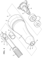
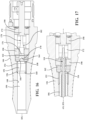
- FIG 1 depicts a perspective view of a surgical handpiece system 10.
- the surgical handpiece system 10 includes a motor 12, a hub 14 and a nose tube assembly 16.
- the motor 12 connects to the hub 14, and the nose tube assembly 16 connects to the motor 12 through the hub 14.
- the nose tube assembly 16 includes a nose tube 17, a driveshaft 24 (see Figure 2 ), and a cutting tool 18 coupled to the driveshaft 24.
- the motor 12 is configured to provide torque through the hub 14 to the nose tube assembly 16. Specifically, the motor 12 transfers torque through the hub 14 to the driveshaft 24 of the nose tube assembly 16 that rotates a cutting tool 18 of the nose tube assembly 16 disposed at a distal end 21 of the nose tube assembly 16.
- the motor 12 is configured to transfer torque through the hub 14 and the nose tube assembly 16 to the cutting tool 18.
- the motor 12 is configured to rotate the cutting tool 18 at speeds greater than 50,000 revolutions per minute.
- the high-speed torque transfer from the motor 12 to the cutting tool 18 allows the nose tube assembly 16 to accurately and efficiently abrade a nasal passage, for example.
- the nose tube assembly 16 may also be adapted for spinal, neuro, and endoscopic applications.
- the hub 14 may include a variety of different configurations.
- the hub 14 may be straight, or curved depending on use.
- the hub 14 may define a twenty-degree seamless curve away from a horizontal axis 20 of the hub 14, or the hub 14 may define a straight length along the horizontal axis 20.
- the nose tube assembly 16 may also be curved or straight depending on application of the nose tube assembly 16. More specifically, the nose tube 17 may be curved or straight.
- the nose tube assembly 16 may include a bend at a proximal end 22, or may include a bend at the distal end 21 of the nose tube assembly 16.
- Transnasal applications of the nose tube assembly 16 may employ a bend at the distal end 21, and spinal applications of the nose tube assembly 16 may employ a bend at the proximal end 22 of the nose tube assembly 16.
- Bushings (not shown) align the driveshaft 24 within a lumen 26 (see Figure 2 ) of the nose tube 17 so that the driveshaft 24 does not contact an inner surface of the nose tube 17. This allows the driveshaft 24 to rotate independently of the nose tube 17 when the motor 12 transfers torque through the driveshaft 24.
- a curved hub 14 differs from the straight hub based on the desired surgical application of the surgical handpiece system 10. As noted above, the degree to which the hub 14 and/or the nose tube assembly 16 may be bent may be influenced by surgical application. It is contemplated that the hub 14 and/or the nose tube assembly 16 may be straight and not employ any bends.
- the curved hub 14 may include a plurality of ball bearings (not shown) or other torque transfer mechanisms used to support rotatable components that allow the curved hub 14 to transfer torque to the nose tube assembly 16.
- the bearings provide alignment of shafts (not shown) interconnected by a gear set (not shown) to transfer torque from the motor 12 through the hub 14 and to the nose tube assembly 16.
- the hub 14 attaches to the motor 12.
- the hub 14 may include features that aid in aligning and locking the hub 14 to the motor 12 of the surgical handpiece system 10.
- the hub 14 may include a visual indicator such as a dot (not shown) that corresponds to another dot (not shown) on the motor 12 such that alignment between the dots allows the hub 14 to couple to the motor 12.
- the hub 14 may include an anti-rotation pin (not shown) at the proximal end 22 of the hub 14 to allow specific orientations between the hub 14 and the motor 12.
- An external c-clip (not shown) as well as an O-ring (not shown) may further aid to establish a secure connection between the hub 14 and the motor 12 such that the motor 12 transfers torque through the hub 14 to the nose tube assembly 16.
- the hub 14 may also include a knurled portion (not shown). The knurled portion corresponds to a position on the hub 14 where an operator may place a finger to hold the surgical handpiece system 10.
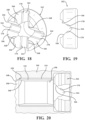
- Figure 2 depicts a cross-sectional view of the surgical handpiece system 10 taken along lines 2-2 in Figure 1 .
- Figure 2 shows a cross-section of the nose tube assembly 16 and the hub 14.
- the motor 12 is not shown in Figure 2 .
- the nose tube assembly 16 is shown having the driveshaft 24 extending through the lumen 26 defined in the nose tube 17.
- the driveshaft 24 extends into the hub 14 and the hub 14 is configured to transfer torque from the motor 12 to the driveshaft 24.
- the driveshaft 24 is shown as extending between and beyond the proximal and distal ends 22, 21 of the nose tube assembly 16.
- the driveshaft 24 is at least partially disposed within the lumen 26.
- the driveshaft 24 also includes an alignment portion 28.
- the alignment portion 28 is configured to align a drive portion 30 of the driveshaft 24 into an orientation to engage a rotatable drive chuck 34 disposed within the hub 14.
- the rotatable drive chuck 34 is placed into alignment with the driveshaft 24 of the nose tube assembly 16 with the hub 14 to transfer torque through the driveshaft 24 from the motor 12.
- the alignment portion 28 of the driveshaft 24 is disposed at the proximal end 22 of the nose tube assembly 16.
- the rotatable drive chuck 34 engages a leading edge 36 of the alignment portion 28 of the driveshaft 24 as the nose tube assembly 16 is urged towards the hub 14.
- the alignment portion 28 defines one or more leading edges 36 to engage one or more ramped surfaces 38 of the rotatable drive chuck 34 to align the drive portion 30 of the driveshaft 24 in the rotatable drive chuck 34.
- the configuration of the ramped surfaces 38 of the rotatable drive chuck 34 and the leading edges 36 of the alignment portion 28 permits the driveshaft 24 to be self-aligning.
- the leading edge 36 of the alignment portion 28 engages the ramped surface of the rotatable drive chuck 30 to rotate the driveshaft 24.
- This engagement and continued urging of the nose tube assembly 16 toward the hub 14 will rotate the driveshaft 24 to an orientation where the drive portion 30 engages the rotatable drive chuck 34 to permit torque transfer between the driveshaft 24 and the rotatable drive chuck 34.
- the configuration of the ramped surfaces 38 of the rotatable drive chuck 34 and the leading edges 36 of the alignment portion 28 will ensure that the drive portion 30 of the driveshaft 24 is in the orientation to engage the rotatable drive chuck 34 when the nose tube assembly 16 is urged toward the hub 14.
- the self-aligning feature is beneficial in certain embodiments because the driveshaft 24 is not visible when the nose tube assembly 16 is coupled to the hub 14 and because the driveshaft 24 is not axially movable within the nose tube assembly 16. Thus, a user grasps the outer surface of the nose tube 17 and urges it towards the hub 14.
- Proper alignment between the hub 14 and the driveshaft 24 may be indicated by tactile feedback. More specifically, when the leading edge 36 of the alignment portion 28 engages the ramped surface 38 of the rotatable drive chuck 34, haptic feedback such as, for example, vibrations from contact between the leading edge 36 and the ramped surface 38, may be felt through the surgical handpiece system 10. The haptic feedback may be indicative of proper alignment between the nose tube assembly 16, the hub 14, and the motor 12.
- the drive portion 30 of the driveshaft 24 mates with flat surfaces 40 within a drive chamber 42 of the rotatable drive chuck 34.
- This allows torque to transfer from the motor 12 through the hub 14 to the driveshaft 24.
- the motor 12 transfers torque through the hub 14 once the drive portion 30 aligns with the flat surface 40 in the drive chamber 42 of the rotatable drive chuck 34, in which the rotatable drive chuck 34 rotates independently from the hub 14.
- Bearings 44 disposed within the hub 14 aid to align the driveshaft 24 and rotatable drive chuck 34 along the horizontal axis 20 of the surgical handpiece system 10. Therefore, the bearings 44 allow for efficient torque transfer along the horizontal axis 20 by aligning the rotatable drive chuck 34 and driveshaft 24 within the hub 14, and nose tube assembly 16, respectively.
- Figure 3 depicts a partial, cross-sectional view of the driveshaft 24 disposed within the hub 14 taken along lines 3-3 shown in Figure 1 .
- Figure 3 depicts the drive portion 30 of the driveshaft 24 aligned within the drive chamber 42 of the rotatable drive chuck 34.
- Bearings 44 are shown engaging the driveshaft 24 and rotatable drive chuck 34 to align the driveshaft 24 and rotatable drive chuck 34 along the horizontal axis 20, and allow the driveshaft 24 and rotatable drive chuck 34 to rotate independently of the hub 14.
- Independent rotation of the driveshaft 24 and rotatable drive chuck 34 relative to the hub 14 allows the motor 12 to transfer torque through the hub 14 to the cutting tool 18, such as a bur.
- the nose tube 17 of the nose tube assembly 16 defines a recess 48 disposed at the proximal end 22 of the nose tube 17, and adjacent the bearings 44 when the nose tube assembly 16 is coupled to the hub 14.
- the nose tube 17 has an outer surface 56 that defines the recess 48 for receiving a biasing member 46, such as a c-clip, to constrain a depth of the nose tube assembly 16 relative to the surgical handpiece system 10.
- the biasing member 46 is held axially in place using the hub 14.
- the biasing member 46 expands as the nose tube assembly 16 is inserted such that the biasing member 46 then seats within the recess 48 when the nose tube assembly 16 is fully inserted into the hub 14.
- the biasing member 46 is disposed in the recess 48 to hold the nose tube assembly 16 in place along the horizontal axis 20 during use of the surgical handpiece system 10.
- the recess 48 may also be referred to as a retention feature 48, in which the biasing member 46 is disposed in the retention feature 48 to maintain axial alignment of the nose tube assembly 16 and the driveshaft 24 relative to the hub 14 during use of the surgical handpiece system 10.
- the biasing member 46 may be referred to as a retention element as the biasing member 46 serves to retain the depth of the nose tube assembly 16 relative to the hub 14 by engaging the retention feature.
- the biasing member 46 prevents axial movement of nose tube assembly 16 relative to the hub 14. More specifically, the biasing member 46 prevents the nose tube assembly 16 from inadvertently separating from the hub 14 when the biasing member 46 engages the recess 48.
- the engagement between the biasing member 46 and the recess 48 may be overcome in response to the user applying a force (e.g., by pulling) sufficient to expand the biasing member 46 out of the recess 48 to separate the nose tube assembly 16 from the hub 14.
- the biasing member 46 aids to constrain the nose tube assembly 16 along the horizontal axis 20 relative to the hub 14.
- the recess 48 may define a beveled edge 50 that may be positioned adjacent to a projection 52 of the nose tube 17 extending radially away from the lumen 26 of the nose tube 17 such that the biasing member 46 abuts the projection 52.
- the beveled edge 50 of the recess 48 may reduce the force required by the user to remove the nose tube assembly 16 from the hub 14.
- the driveshaft 24 includes a retention portion 27 disposed distal the alignment portion 28 and the drive portion 30 of the driveshaft 24.
- the retention portion 27 of the driveshaft 24 may be disposed within the lumen 26 of the nose tube 17.
- the retention portion 27 is configured to extend partially into the nose tube assembly 16 and abut a shelf 33 of the internal surface of the nose tube 17 defining the lumen 26 to constrain the driveshaft 24 relative to the nose tube 17.
- a bearing may be interposed between the shelf 33 and the retention portion 27 of the driveshaft 24.
- the retention portion 27 defines a diameter 29 being greater than a diameter 31 of the lumen 26 to allow the retention portion 27 to constrain the driveshaft 24 relative to the nose tube assembly 16.
- This configuration prevents the driveshaft 24 from being removed axially from the nose tube 17 in a distal direction.
- the relative diameter of the cutting tool 18 in relation to the lumen 26 and/or a distal bushing 35 (see Figure 2 ) coupled to the distal end 21 of the nose tube 17 prevents the driveshaft 24 from being removed axially from the nose tube 17 in a proximal direction.
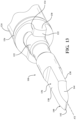
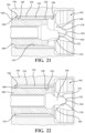
- Figure 4 depicts a partial, perspective, exploded view of the nose tube assembly 16 and the hub 14 of the surgical handpiece system 10.
- Figure 4 is shown as exploded along the horizontal axis 20, in which the nose tube assembly 16 and the hub 14 are spaced along the horizontal axis 20.
- Figure 4 depicts an exploded, perspective view of the nose tube assembly 16 having the projection 52 that extends radially from the surface 56.
- Figure 5 depicts a partial perspective view of the nose tube assembly 16 detached from the hub 14.
- Figure 6 depicts a partial perspective view of the nose tube assembly 16 defining the recess 48 and the projection 52 on the surface 56 and the rotatable drive chuck 34.
- the hub 14 has a proximal end 62 and a distal end 60 opposite the proximal end 62.
- the hub 14 has an internal surface defining a bore 58 extending from the distal end 60 to the proximal end 62.
- the internal surface also defines a channel 54 in communication with the bore 58 extending from the distal end 60 toward the proximal end 62.
- the projection 52 of the nose tube 17 is adapted to radially align the nose tube 17 during insertion of the nose tube assembly 16 into the bore 58 of the hub 14. In this way, the projection 52 acts as a radial alignment feature 52 of the nose tube 17.
- the projection 52 extends radially from the nose tube 17. Specifically, the projection 52 extends vertically from a surface 56 of the nose tube 17. Extending from the surface 56 of the nose tube 17 allows the projection 52 to engage the channel 54 defined in the hub 14 such that radial movement of the projection 52 in the channel 54, for example, from rotating the nose tube 17 relative to the hub 14, is prevented.
- the engagement of the projection 52 in the channel 54 also serves to grossly align the drive portion 30 of the driveshaft 24 in the drive chamber 42 of the rotatable drive chuck 34. In this way, the projection 52 provides efficient and accurate alignment.
- the projection 52 extends from the surface 56 of the nose tube 17 to a peak 66.
- the peak 66 defines a height of the projection 52.
- the height of the projection 52 may be based on dimensions of the hub 14.
- the peak 66 of the projection 52 may be formed from at least one, first, slanted surface 72.
- the projection 52 may also be formed from two, first and second, slanted surfaces 72, 74.
- the peak 66 may extend from the first slanted surface 72 to the second slanted surface 74.
- the first slanted surface 72 may extend from the beveled edge 50 of the recess 48 to the peak 66 of the projection 52.
- the second slanted surface 74 may be disposed along the alignment portion 28 of the driveshaft 24, and extend to the peak 66 of the projection 52.
- the first and second slanted surfaces 72, 74 may also define opposite inclinations such that the first and second slanted surfaces 72, 74 culminate at the peak 66 of the projection 52. Angles that form the inclination of the first and second slanted surfaces 72, 74 may vary, or be equal based on an optimal extension and operation of the projection 52 as the projection 52 slides in the channel 54.
- the peak 66 may extend between the first and second slanted surfaces 72, 74 to interconnect the first and second surfaces 72, 74, which defines the height of the projection 52.
- the first and second slanted surfaces 72, 74 also aid to allow the projection 52 to slide into the channel 54 in the hub 14.
- the first and second slanted surfaces 72, 74 provide ease of assembly by reducing frictional forces as the projection 52 slides through the channel 54.
- the peak 66 may define a radius between the first and second slanted surfaces 72, 74.
- the peak 66 may be rounded between the first and second slanted surfaces 72, 74.
- the radius of the peak 66 may be determined based on optimal sliding parameters of the projection 52 in the channel 54. Therefore, the radius of the peak 66 may be formed to fit within the channel 54 defined in the hub 14.
- Other shapes of the projection 52 are also contemplated.
- the projection 52 is disposed adjacent to the recess 48.
- the first slanted surface 72 is formed proximate the beveled edge 50 of the recess 48.
- Both the retention (shown as the recess) and radial alignment features (shown as the projection) 48, 52 of the nose tube assembly 16 may be disposed adjacent to each other. Since the projection 52 is disposed adjacent the recess 48, the biasing member 46 abuts the projection 52 on the nose tube 17 when the nose tube assembly 16 is coupled to the hub 14.
- the projection 52 defines the height of the peak 66 relative to the horizontal axis 20and the recess 48 defines a distance to the horizontal axis 20 being less than the height of the peak 66.
- the height of the peak 66 being greater than the distance from the biasing member 46 to the horizontal axis 20 allows the projection 52 to adequately engage and slide in the channel 54 formed in the hub 14.
- the recess 48 defined the distance from the horizontal axis 20 as being greater than the height of the peak 66, the peak 66 may not engage the channel 54, and rotational misalignment between the nose tube 17 and the hub 14 may be introduced during use of the surgical handpiece system 10. Therefore, the distance from the recess 48 to the horizontal axis 20 being less than the height of the peak 66 allows the projection 52 to maintain rotational alignment between the nose tube 17 and the hub 14 during use of the surgical handpiece system 10, while subsequently allowing the retention feature 48 to maintain axial alignment of the nose tube assembly 16, and hence the driveshaft 24, with the features of the hub 14.
- the first region 84 may represent the majority of the length of the nose tube 17, while the second region 86 may be the portion of the nose tube 17 that interacts with the hub 14.
- the first region 84 and second region 86 may both be formed from a metallic material, such as stainless steel.
- the second region 86 may extend monolithically from the first region 84 from a single piece of metal stock.
- the nose tube 17, including both the first region 84 and the second region 86 may be formed from a single piece of metal stock.
- the second region 86 may include the radial alignment feature 52 and an axial retention feature 48 to axially retain the nose tube assembly 16 in the surgical handpiece system 10.
- the alignment and retention features 52, 48 may be formed from the metallic material that forms the first and second regions 84, 86, and hence the alignment features 52 and the retention features 48 may be machined from the same piece of metal stock that is used to machine the first region 84 of the nose tube 17.
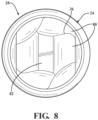
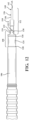
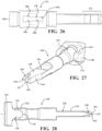
- Figure 7 depicts a perspective view of the alignment portion 28 including the leading edge 36, the retaining portion 27, and the drive portion 30.
- Figure 8 depicts a front view of the proximal portion of the driveshaft 24. Specifically, Figure 8 depicts a front view of the alignment portion 28 of the driveshaft 24.
- a user grasps the nose tube 17 of the nose tube assembly 16.
- the user partially inserts the nose tube assembly 16 within the bore 58 of the hub 14.
- the user aligns the projection 52 of the nose tube 17 with the channel 54 of the hub 14 and continues to urge the nose tube assembly 16 toward the hub 14.
- the engagement between the projection 52 and the channel 54 radially aligns the nose tube 17 to the hub 14.
- the biasing member 46 expands to accommodate the nose tube 17.
- the recess 48 receives the biasing member 46, the nose tube 17 and the rest of the nose tube assembly 16 are axially retained relative to the hub 14.
- the leading edge 36 of the alignment portion 28 of the driveshaft 24 abuts the ramped surface 38 of the rotatable drive chuck 34 to cam the driveshaft 24, and thus the drive portion 30 of the driveshaft 24, toward the orientation where the drive portion 30 of the driveshaft 24 engages the rotatable drive chuck 34.
- the driveshaft 24 has been cammed into the orientation with the drive portion 30 received in the drive chamber 42 of the rotatable drive chuck 34 and the drive portion 30 abutting the flat surface 40 of the rotatable drive chuck 34 to receive torque from and rotate with the rotatable drive chuck 34.
- the leading edge 36 of the alignment portion 28 may first contact the ramped surface 38 of the rotatable drive chuck 34 at different axial positions of the nose tube 17 relative to the hub 14. It is contemplated that where the initial radial orientation of the driveshaft 24 is already in the orientation required for the drive portion 30 of the driveshaft 24 to be received in the drive chamber 42 and engage the rotatable drive chuck 34, the leading edge 36 of the alignment portion 28 would not contact the ramped surface 38 of the rotatable drive chuck 34.
- the axial position of the driveshaft 24 relative to the rotatable drive chuck 34 is maintained by the axial retention of the nose tube 17 to the hub 14 via the biasing member 46 and the recess 48.
- the driveshaft 24 is axially retained relative to the nose tube 17, the axial position of the driveshaft 24 relative to the hub 14 and rotatable drive chuck 34 is tied to the axial position of the nose tube 17 relative to the hub 14 and the rotatable drive chuck 34.
- the nose tube 17 is retained by the biasing member 46 until the user pulls the nose tube assembly 16 relative to the hub 14 with sufficient force to overcome the biasing member 46 by expanding the biasing member 46.
- the alignment portion 28 of the driveshaft 24 defines the leading edge 36 that aids to align the drive portion 30 of the driveshaft 24 in the drive chamber 42 of the rotatable drive chuck 34.
- the leading edge 36 engages the ramped surface 38 of the drive chamber 42 in the rotatable drive chuck 34 to align the drive portion 30 of the driveshaft 24 in the drive chamber 42 of the rotatable drive chuck 34.
- the leading edge 36 engages the ramped surface 38 to translate an insertion force into a rotational force to provide alignment between the drive portion 30 of the driveshaft 24 and the rotatable drive chuck 34. While described as a single leading edge 36, the alignment portion 28 of the driveshaft 24 may include one or more leading edges 36.
- Figure 6 depicts the leading edges 36 as being defined between at least two curved surfaces 80 defined on the alignment portion 28 of the driveshaft 24.
- the curved surfaces 80 that interconnect to define the leading edges 36.
- the leading edges may be asymmetrical across the horizontal axis 20.
- the curved surfaces 80 connect to form a tip 82 of the alignment portion 28.
- the tip 82 as shown in Figures 7 and 8 , resembles a parallelogram.
- the rotatable drive chuck 34 rotates independently of the hub 14.
- the alignment portion 28 engages the ramped surface 38 of the rotatable drive chuck 34 to alignment the drive portion 30 in the drive chamber 42.
- leading edge 36 contacts the ramped surface 38 to cause a cam rotation of the driveshaft 24 to ensure proper alignment of the drive portion 30 in the drive chamber 42. Therefore, the leading edges 36 further aid to align the drive portion 30 of the driveshaft 24 with the flat surface 40 in the drive chamber 42 to accurately transfer torque from the motor 12 to the cutting tool 18 disposed at the distal end 21 of the nose tube assembly 16.
- FIG. 9-25 another configuration of the surgical handpiece system 100 is illustrated. It should be appreciated that the configuration of the surgical handpiece system 10 described above may include similar elements to the surgical handpiece system 100 described below and vice versa.
- the surgical handpiece system 100 comprises a high-speed surgical bur assembly 102 ( Figure 10 ) and a surgical handpiece assembly 104 ( Figure 14 ).
- the surgical handpiece system 100 may also comprise a motor (not shown) configured to be coupled to the surgical handpiece assembly 104 to provide torque to the surgical handpiece system 100.
- the high-speed surgical bur assembly 102 comprises a nose tube 106.
- the nose tube 106 defines a lumen extending between a proximal end and a distal end of the nose tube 106. At least a proximal portion 108 of the nose tube 106 extends along an axis AX.
- the nose tube 106 may include a bend such as a distal bend of the nose tube 106 illustrated in Figure 11 rather than extend axially along an entire length of the nose tube 106. The bend may assist a user in positioning the distal end of the nose tube 106 in certain advantageous positions during surgery.
- the high-speed surgical bur assembly 102 further comprises a driveshaft 110 that is at least partially disposed within the lumen of the nose tube 106.
- the driveshaft 110 is configured to rotate relative to the nose tube 106.
- a proximal region 112 of the driveshaft 110 is configured to engage the surgical handpiece assembly 104 as described in greater detail further below.
- the high-speed surgical bur assembly 102 further comprises a cutting tool 114 that is coupled to a distal region of the driveshaft 110.
- the cutting tool 114 is configured to rotate with the driveshaft 110 relative to the nose tube 106.
- the cutting tool 114 is a bur.
- the cutting tool 114 comprises another rotary tool configured to abrade tissue.
- the high-speed surgical bur assembly 102 may comprise bushings 116, 118, 120 for facilitating relative rotation between the driveshaft 110 and the nose tube 106.
- a proximal bushing 116 may be coupled to the nose tube 106 and disposed at least partially within the lumen of the nose tube 106 and around the driveshaft 110.
- a distal bushing 118 may be coupled to the nose tube 106 and disposed at least partially within the lumen of the nose tube 106 and around the driveshaft 110.
- a middle bushing 120 may be disposed within the lumen between the proximal and distal bushings 116, 120 to prevent contact between the driveshaft 110 and the nose tube 106 within the lumen of the nose tube 106. In one configuration, the middle bushing 120 is fixed to the nose tube 106.
- the proximal and distal bushings 116, 118 retain the middle bushing 120 within the lumen of the nose tube 106.
- the middle bushing 120 is retained in the lumen of the nose tube 106 by the bend in the nose tube 106 and corresponding bend of the middle bushing 120.
- the proximal and distal bushings 116, 118 may also serve as retention features for coupling the driveshaft 110 to the nose tube 106.
- the proximal region 112 of the driveshaft 110 comprises a retention portion 122 proximal to the proximal bushing 116.
- the retention portion 122 of the proximal region 112 of the driveshaft 110 has an outer diameter greater than an inner diameter of the proximal bushing 116 to prevent movement of the driveshaft 110 in a distal direction relative to the nose tube 106.
- the cutting tool 114 may have an outer diameter greater than an inner diameter of the distal bushing 118 to prevent movement of the driveshaft 110 in a proximal direction relative to the nose tube 106.
- the driveshaft 110 is coupled to the nose tube 106 in another manner to permit relative rotation between the driveshaft 110 and the nose tube 106 and prevent axial movement between the driveshaft 110 and the nose tube 106.
- the proximal portion 108 of the nose tube 106 has an outer surface.
- the outer surface may define a recess 124 for engaging the surgical handpiece assembly 104 to constrain a depth of the nose tube 106 relative to the surgical handpiece assembly 104.
- the outer surface of the proximal portion 108 of the nose tube 106 may have a proximal shoulder 126 that defines a proximal end of the recess 124 and a distal shoulder 128 that defines a distal end of the recess 124. Either or both proximal and distal shoulders 126, 128 may be tapered.
- the nose tube 106 comprises a projection 130 disposed proximal to the recess 124.
- the projection 130 is configured to constrain a radial orientation of the nose tube 106 relative to the surgical handpiece assembly 104.
- the projection 130 extends proximally and generally parallel to the axis AX.
- the proximal end of the projection 130 may comprise a rounded surface 132.
- the projection 130 of the proximal portion 108 of the nose tube 106 may include a flat surface 134 that is parallel to the axis AX of the proximal portion 108 of the nose tube 106.
- the rounded and flat surfaces 132, 134 of the projection 130 may assist engagement between the nose tube 106 and the surgical handpiece assembly 104. Engagement between the nose tube 106 and the surgical handpiece assembly 104 is discussed in greater detail further below.
- the nose tube 106 comprises two projections 130 to constrain the radial orientation of the nose tube 106 relative to the surgical handpiece assembly 104. It is contemplated that a single projection 130 may be used instead to constrain the radial orientation of the nose tube 106 relative to the surgical handpiece assembly 104. It is also contemplated that three or more projections 130 may be employed to constrain the radial orientation of the nose tube 106 relative to the surgical handpiece assembly 104.
- the proximal region 112 of the driveshaft 110 is rotatable about the axis AX of the proximal portion 108 of the nose tube 106.
- the proximal region 112 of the driveshaft 110 comprises a drive portion 136 proximal to the retention portion 122 for engaging the surgical handpiece assembly 104 in a driving orientation.
- the drive portion 136 may comprise two or more drive surfaces 138 for engaging the surgical handpiece assembly 104.
- the drive surfaces 138 may be flat and parallel to the axis AX.
- the proximal region 112 of the driveshaft 110 may also comprise an alignment portion 140 proximal to the drive portion 136 of the driveshaft 110.
- the alignment portion 140 has an outer surface tapering toward the axis AX as the alignment portion 140 extends from the drive portion 136 to a proximal end of the driveshaft 110.
- the alignment portion 140 is configured to engage the surgical handpiece assembly 104 to align the drive portion 136 to the driving orientation.
- the alignment portion 140 comprises a proximal edge 142 adjacent the proximal end of the proximal region 112 of the driveshaft 110 to engage the surgical handpiece assembly 104.
- the alignment portion 140 may comprise a flat or rounded surface instead of the proximal edge 142.
- the alignment portion 140 may define a notch 144 extending distally from the proximal end of the driveshaft 110 for mitigating contact between the alignment portion 140 of the driveshaft 110 and the surgical handpiece assembly 104 during engagement. Mitigating the amount of contact during engagement may reduce potential jamming during engagement resulting from multiple points of contact. In other configurations, the alignment portion 140 may not define the notch 144.
- the proximal region 112 of the driveshaft 110 is disposed outside of the lumen of the nose tube 106 and proximal the proximal portion 108 of the nose tube 106. In other configurations, the proximal region 112 of the driveshaft 110 may be disposed at least partially within the lumen of the nose tube 106 or distal the proximal portion 108 of the nose tube 106. Engagement between the proximal region 112 of the driveshaft 110 and the surgical handpiece assembly 104 is discussed in greater detail further below.
- the alignment portion 140 of the driveshaft 110 may comprise a proximal surface 194 disposed proximally of the proximal edge 142 to prevent the proximal edge 142 from engaging the rotatable drive chuck 172 of the surgical handpiece assembly 104 after the drive portion 136 is aligned in the driving orientation.
- the proximal surface 194 may comprise a planar surface perpendicular to the axis AX. In other configurations, the proximal surface 194 may comprise a rounded surface.
- the surgical handpiece assembly 104 comprises a hub 146.
- the hub 146 has a bore 148 defining a cavity 150 for receiving at least part of the high-speed surgical bur assembly 102.
- the cavity 150 is configured to receive at least the proximal portion 108 of the nose tube 106 and the proximal region 112 of the driveshaft 110 of the high-speed surgical bur assembly 102.
- a proximal portion of the hub 146 may be configured to be coupled to a motor housing (not shown) that includes a motor, similar of the motor 12 coupling to the hub 14 in the configuration illustrated in Figure 1 .
- the surgical handpiece assembly 104 further comprises a biasing member 152 disposed within the cavity 150 of the hub 146.
- the biasing member 152 may be a C-clip.
- the bore 148 of the hub 146 may define a recess 154 in communication with the cavity 150.
- the recess 154 defined by bore 148 of the hub 146 is configured to receive the biasing member 152.
- the bore 148 of the hub 146 may have a distal shoulder 156 that defines a distal end of the recess 154 in the hub 146.
- the distal shoulder 156 retains the biasing member 152 from exiting the recess 154 of the hub 146 in a distal direction.
- the biasing member 152 When the high-speed surgical bur assembly 102 is received by the cavity 150 of the hub 146 of the surgical handpiece assembly 104, the biasing member 152 is received by the recess 124 of the nose tube 106.
- the biasing member 152 may be configured to engage one or both the proximal and distal shoulders 126, 128 of the recess 124 of the nose tube 106 to constrain a depth of the nose tube 106 of the high-speed surgical bur assembly 102 within the cavity 150 of the hub 146 relative to the hub 146.
- the biasing member 152 may have tapered surfaces 158, 160 on the proximal or distal ends to assist in engagement between the biasing member 152 and the nose tube 106.
- the surgical handpiece assembly 104 may also comprise a radial alignment member 162 disposed within the cavity 150 of the hub 146 proximal to the biasing member 152.
- the radial alignment member 162 may be press-fit into the cavity 150 of the hub 146 such that no relative movement between the hub 146 and the radial alignment member 162 occurs. It is contemplated that the radial alignment member 162 and the hub 146 may be coupled to each other in another manner so long as no relative movement is permitted between the radial alignment member 162 and the hub 146.
- the radial alignment member 162 defines a notch 164 for receiving the projection 130 of the nose tube 106 to constrain a radial orientation of the nose tube 106 relative to the hub 146.
- the radial alignment member 162 defines four notches 164 spaced circumferentially at equal angles relative to each other such that each notch 164 is spaced 90 (ninety) degrees from adjacent notches 164. It is contemplated that three or fewer notches 164 may be employed for receiving the projection 130 of the nose tube 106 to constrain a radial orientation of the nose tube 106 relative to the hub 146.
- notches 164 may be used for receiving the projection 130 of the nose tube 106 to constrain a radial orientation of the nose tube 106 relative to the hub 146. Further, it is contemplated that the spacing between the notches 164 may be unequal and disposed at any position arranged circumferentially. It is appreciated that the number of notches 164 may determine the number of possible radial orientations of the nose tube 106 relative to the hub 146. Further, the spacing of the notches 164 may determine how far apart the radial orientations are. Permitting multiple orientations may be particularly advantageous when the nose tube 106 employs a bend. The bend may be oriented differently relative to the surgical handpiece assembly 104 based on which notch 164 of the radial alignment member 162 receives the projection 130 of the nose tube 106.
- the radial alignment member 162 may have an alignment wall 166 extending distally from the notch 164 for engaging the projection 130 of the nose tube 106.
- the alignment wall 166 may radially position the nose tube 106 during engagement to permit the notch 164 to receive the projection 130 of the nose tube 106 if the projection 130 is not already radially aligned with the notch 164 of the radial alignment member 162.
- Two alignment walls 166 may be employed for each notch 164 of the radial alignment member 162; one on each side.
- Each of the two alignment walls 166 may taper inwardly toward the notch 164 such that contact between the alignment wall 166 of the radial alignment member 162 and the projection 130 of the nose tube 106 when the nose tube 106 is axially forced into the hub 146 results in relative rotation between the nose tube 106 and the hub 146 to orient the projection 130 into the notch 164.
- consecutive alignment walls 166 between notches 164 may be tapered in opposite directions.
- the consecutive alignment walls 166 may also collectively form an edge 168 to mitigate a possibility of the projection 130 jamming into the radial alignment member 162 instead of radially positioning the projection 130 of the nose tube 106 into a notch 164 of the radial alignment member 162.
- Configurations where the projection 130 has a rounded surface 132 further assists in mitigating jamming with the radial alignment member 162.
- the radial alignment member 162 may also include one or more flat surfaces 170 to further define each notch 164.
- the flat surfaces 170 of the radial alignment member 162 may engage flat surfaces 134 of the projection 130 of the nose tube 106 when the projection 130 is received in the notch 164 to prevent relative rotation between the nose tube 106 and the hub 146. With relative rotation between the nose tube 106 and the hub 146 prevented, axial movement between the nose tube 106 and the hub 146 resulting from the relative rotation is also prevented.
- the radial alignment member 162 assists the distal shoulder 156 of the recess 154 of the hub 146 to retain the biasing member 152 in the recess 154 of the hub 146. As noted above, the distal shoulder 156 prevents the biasing member 152 from exiting the recess in a distal direction. With the radial alignment member 162 positioned immediately proximal the biasing member 152, the radial alignment member 162 forms a proximal shoulder of the recess 154 to prevent the biasing member 152 from exiting the recess 154 in a proximal direction.
- the bore 148 of the hub 146 may include a proximal shoulder (not shown) to define the proximal end of the recess 154 and the radial alignment member 162 may be positioned proximal to the proximal shoulder.
- the biasing member 152 is configured to engage the distal shoulder 156 of the hub 146 and the proximal shoulder 126 of the nose tube 106 when the nose tube 106 is inserted in the cavity 150 of the hub 146 to force the projection 130 of the nose tube 106 toward the notch 164 of the radial alignment member 162. If the projection 130 is already partly received by the notch 164, engagement between the biasing member 152 and the shoulders 126, 156 may force the projection 130 deeper into the notch 164 until engagement ceases or until the projection 130 abuts a proximal surface of the notch 164 and is fully received by the notch 164.
- the surgical handpiece assembly 104 also comprises a rotatable drive chuck 172.
- the rotatable drive chuck 172 is configured to be rotated by a motor about a hub axis HX.
- a proximal portion 174 of the rotatable drive chuck 172 may engage a motor directly or the rotatable drive chuck 172 may engage a gear assembly or another assembly driven by a motor and configured to transfer torque from the motor to the rotatable drive chuck 172.
- the rotatable drive chuck 172 is disposed at least partially within the cavity 150 of the hub 146 proximal to the radial alignment member 162 and configured to rotate relative to the hub 146.
- the rotatable drive chuck 172 defines an opening 176 for receiving the proximal region 112 of the driveshaft 110.
- the rotatable drive chuck 172 comprises a driving portion 178 proximal of the opening 176.
- the driving portion 178 has at least two driving surfaces 180 configured to engage the drive portion 136 of the proximal region 112 of driveshaft 110 to rotate the driveshaft 110.
- the driving surfaces 180 of the driving portion 178 of the rotatable drive chuck 172 engage the drive surfaces 138 of the drive portion 136 of the driveshaft 110 when the driveshaft 110 is in the driving orientation and the high-speed surgical bur assembly 102 is coupled to the surgical handpiece assembly 104 (see Figure 17 ).
- the driveshaft 110 is in the driving orientation when the drive surfaces 138 of the driveshaft 110 are parallel to driving surfaces 180 of the driving portion 178 of the rotatable drive chuck 172.
- the driving portion 178 comprises eight driving surfaces 180 to accommodate various orientations of the drive portion 136 of the driveshaft 110. It is contemplated that there are multiple driving orientations when there are more than two driving surfaces 180. For instance, in the configuration illustrated in Figures 23-25 , there are four different driving orientations. Said differently, the driveshaft 110 may be rotated by the rotatable drive chuck 172 in four different radial orientations relative to the rotatable drive chuck 172.
- the driving portion 178 may instead comprise between three and seven driving surfaces 180 to engage the drive portion 136 of the driveshaft 110. It is also contemplated that the driving portion 178 may instead comprise nine or more driving surfaces 180 to engage the drive portion 136 of the driveshaft 110.
- the rotatable drive chuck 172 may also comprise an aligning portion 182 disposed between the driving portion 178 and the opening 176 of the rotatable drive chuck 172.
- the aligning portion 182 may have an alignment edge 184 extending distally from the driving portion 178 of the rotatable drive chuck 172 toward the opening of the rotatable drive chuck 172.
- the alignment edge 184 tapers away from the hub axis HX as the alignment edge 184 extends distally from the driving portion 178 of the rotatable drive chuck 172.
- the alignment edge 184 of the aligning portion 182 is configured to engage the alignment portion 140 of the driveshaft 110 to rotate the driveshaft 110 into the driving orientation.
- the aligning portion 182 of the rotatable drive chuck 172 may have a first ramped surface 186 extending distally from the driving portion 178 of the rotatable drive chuck 172 toward the opening 176 of the rotatable drive chuck 172.
- the first ramped surface 186 tapers away from the hub axis HX as the first ramped surface 186 extends distally from the driving portion 178 of the rotatable drive chuck 172.
- the aligning portion 182 of the rotatable drive chuck 172 may have a second ramped surface 188 distinct from and adjacent to the first ramped surface 186.
- the second ramped surface 188 extends distally from the driving portion 178 of the rotatable drive chuck 172 toward the opening 176 of the rotatable drive chuck 172.
- the second ramped surface 188 tapers away from the hub axis HX as the second ramped surface 188 extends distally from the driving portion 178 of the rotatable drive chuck 172.
- the first and second ramped surfaces 186, 188 collectively define the alignment edge 184 of the rotatable drive chuck 172.
- the aligning portion 182 comprises four alignment edges 184. Each alignment edge 184 is formed by a first ramped surface 186 and a second ramped surface 188.
- coupling between the high-speed surgical bur assembly 102 and the surgical handpiece assembly 104 is described below.
- a user may grasp the nose tube 106 of the high-speed surgical bur assembly 102 or another portion of the high-speed surgical bur assembly 102 and axially load ( i.e., insert) the proximal portion 108 of the nose tube 106 and the proximal region 112 of the driveshaft 110 into the cavity 150 of the hub 146 of the surgical handpiece assembly 104.
- the nose tube 106 and driveshaft 110 After the nose tube 106 and driveshaft 110 have entered the cavity 150 to a certain depth, the nose tube 106 is radially and axially constrained relative to the hub 146 of the surgical handpiece assembly 104 and the driveshaft 110 is radially and axially constrained relative to the rotatable drive chuck 172 of the surgical handpiece assembly 104.
- the driveshaft 110 is axially constrained to the nose tube 106 by the proximal and distal bushings 116, 118 of the high-speed surgical bur assembly 102.
- the rotatable drive chuck 172 is axially constrained within the cavity 150 of the hub 146 by bushings 190 (see Figure 15 ) coupled to the hub 146.
- the driveshaft 110 is axially constrained relative to the rotatable drive chuck 172 when the nose tube 106 is axially constrained to the hub 146.
- the driveshaft 110 is radially constrained relative to the rotatable drive chuck 172 prior to the nose tube 106 being radially constrained to the hub 146.
- the driveshaft 110 and nose tube 106 may be radially constrained simultaneously.
- the nose tube 106 may be radially constrained before the driveshaft 110. After both the driveshaft 110 and the nose tube 106 are radially constrained the nose tube 106 is axially constrained. Below, one exemplary configuration of constraining the nose tube 106 and the driveshaft 110 are described.
- the driveshaft 110 of the high-speed surgical bur assembly 102 enters the cavity 150 of the hub 146 of the surgical handpiece assembly 104
- the driveshaft 110 enters through the opening 176 of the rotatable drive chuck 172.
- the outer surface of the alignment portion 140 of the driveshaft 110 abuts one of the alignment edges 184 of the aligning portion 182 of the rotatable drive chuck 172.
- the engagement between the alignment portion 140 of the driveshaft 110 and the alignment edge 184 of the rotatable drive chuck 172 orients the drive portion 136 of the driveshaft 110 to the driving orientation.
- the drive surfaces 138 of the driveshaft 110 may engage the driving surfaces 180 of the rotatable drive chuck 172 to radially constrain the driveshaft 110 to the rotatable drive chuck 172.
- torque may be transferred from the rotatable drive chuck 172 to the driveshaft 110 and ultimately to the cutting tool 114.
- the rotatable drive chuck 172 may define a cut-out 192 for providing additional clearance between the rotatable drive chuck 172 and the proximal end of the driveshaft 110 when the high-speed surgical bur assembly 102 is coupled to the surgical handpiece assembly 104.
- the additional clearance provided by the cut-out 192 may mitigate the chance that engagement between the proximal end of the driveshaft 110 and a surface of the rotatable drive chuck 172 occurs before the nose tube 106 is axially constrained to the hub 146.
- the additional clearance provided by the cut-out 192 ensures that continued insertion of the driveshaft 110 in the rotatable drive chuck 172 does not interfere with axial coupling of the nose tube 106 to the hub 146.
- Engagement between the alignment portion 140 of the driveshaft 110 and the aligning portion 182 of the rotatable drive chuck 172 may permit rotation of the driveshaft 110 to the driving orientation to be accomplished exclusively by the user axially loading the high-speed surgical bur assembly 102 into the cavity 150 of the hub 146 of the surgical handpiece assembly 104.
- the driveshaft 110 may be oriented to the driving orientation without a user grasping the cutting tool 114 or another portion of the driveshaft 110 to manipulate the driveshaft 110 to the driving orientation. It is contemplated that in some instances, the driveshaft 110 will enter the cavity 150 of the hub 146 in the driving orientation.
- the alignment portion 140 of the driveshaft 110 may not contact the aligning portion 182 of the rotatable drive chuck 172 and the driveshaft 110 may not engage anything until the drive portion 136 of the driveshaft 110 engages the driving portion 178 of the rotatable drive chuck 172.
- the nose tube 106 being axially and radially constrained, is illustrated.
- the driveshaft 110 in Figures 20-22 has been removed to better illustrate the engagement between the nose tube 106 and the surgical handpiece assembly 104.
- the surgical handpiece assembly 104 is shown with the hub 146, the radial alignment member 162, and the biasing member 152.
- the biasing member 152 is shown in an unbiased, compressed state.
- the nose tube 106 engages the biasing member 152 by abutting the distal tapered surface 160 of the biasing member 152.
- the biasing member 152 expands to a biased state shown in Figure 21 to accommodate the proximal portion 108 of the nose tube 106.
- the projection 130 of the nose tube 106 may be misaligned and may engage the alignment wall 166 of the radial alignment member 162 such that continued axial force applied to the nose tube 106 may result in relative rotation between the nose tube 106 and the hub 146 until the projection 130 is aligned with notch 164.
- the nose tube 106 may be oriented so that the projection 130 of the nose tube 106 may be received by the notch 164 of the radial alignment member 162 without a user grasping the nose tube 106 to radially manipulate the nose tube 106.
- the biasing member 152 may be received in the recess 124 of the nose tube 106 and the proximal tapered surface 158 of the biasing member 152 may abut a proximal shoulder 126 of the recess on the nose tube 106 when the nose tube 106 is at a certain depth in the cavity 150 of the hub 146.
- the spring force of the biasing member 152 may be sufficient to engage the nose tube 106 to force the projection 130 of the nose tube 106 deeper into the notch 164 of the radial alignment member 162.
- the biasing member 152 may continue to engage the nose tube 106 to axially constrain the nose tube 106 relative to the hub 146 and to keep a tight axial fit between the hub 146, the biasing member 152, the radial alignment member 162, and the nose tube 106.
- the tight axial fit may eliminate gaps that may have otherwise been present. Such gaps may have been formed from wear, tolerance stack-up, etc.
- the recess 124 of the nose tube 106 receives the biasing member 152 and the biasing member 152 constrains the depth of the nose tube 106 relative to the hub 146.
- the biasing member 152 does not continue to engage the nose tube 106 to keep a tight axial fit between the hub 146, the biasing member 152, the radial alignment member 162, and the nose tube 106.
- the nose tube 106 will enter the cavity 150 of the hub 146 in a radial orientation such that the projection 130 of the nose tube 106 may be received by the notch 164 of the radial alignment member 162 without rotating the nose tube 106.
- the projection 130 of the nose tube 106 may not contact the alignment wall 166 of the radial alignment member 162 and the projection 130 of the nose tube 106 may not engage anything until the projection 130 of the nose tube 106 is received by the notch 164 of the radial alignment member 162.
Landscapes
- Health & Medical Sciences (AREA)
- Surgery (AREA)
- Life Sciences & Earth Sciences (AREA)
- Medical Informatics (AREA)
- Animal Behavior & Ethology (AREA)
- Veterinary Medicine (AREA)
- Public Health (AREA)
- Engineering & Computer Science (AREA)
- Biomedical Technology (AREA)
- Heart & Thoracic Surgery (AREA)
- General Health & Medical Sciences (AREA)
- Molecular Biology (AREA)
- Nuclear Medicine, Radiotherapy & Molecular Imaging (AREA)
- Dentistry (AREA)
- Oral & Maxillofacial Surgery (AREA)
- Orthopedic Medicine & Surgery (AREA)
- Otolaryngology (AREA)
- Pulmonology (AREA)
- Vascular Medicine (AREA)
- Surgical Instruments (AREA)
Claims (15)
- Chirurgische Hochgeschwindigkeitsfräsanordnung (102), die so konfiguriert ist, dass sie Gewebe schneidet und mit einer chirurgischen Handstückanordnung (104) gekoppelt werden kann, die chirurgische Hochgeschwindigkeitsfräsanordnung (102) umfassend:ein Nasenrohr (106), das ein sich zwischen einem proximalen und einem distalen Ende des Nasenrohrs (106) erstreckendes Lumen definiert, wobei das Nasenrohr (106) einen proximalen Abschnitt (108) aufweist, der sich entlang einer Achse (AX) erstreckt, wobei der proximale Abschnitt (108) des Nasenrohrs (106) eine Außenfläche aufweist, die eine Aussparung (124) zur Aufnahme eines Vorspannelements (152) der chirurgischen Handstückanordnung (104) definiert, um eine Tiefe des Nasenrohrs (106) relativ zur chirurgischen Handstückanordnung (104) zu begrenzen, und wobei das Nasenrohr (106) einen Vorsprung (130) umfasst;eine Antriebswelle (110), die zumindest teilweise in dem Lumen des Nasenrohrs (106) angeordnet ist und so konfiguriert ist, dass sie sich relativ zu dem Nasenrohr (106) dreht, wobei die Antriebswelle (110) einen Antriebsabschnitt (136) an einem proximalen Bereich (112) der Antriebswelle (110) aufweist, um mit einem drehbaren Antriebsfutter (172) der chirurgischen Handstückanordnung (104) in Eingriff gebracht zu werden; undein Schneidwerkzeug (114), das mit einem distalen Bereich der Antriebswelle (110) gegenüber dem Antriebsabschnitt (136) gekoppelt ist, wobei das Schneidwerkzeug (114) so konfiguriert ist, dass es sich mit der Antriebswelle (110) relativ zum Nasenrohr (106) als Reaktion auf die Drehung des drehbaren Antriebsfutters (172) der chirurgischen Handstückanordnung (104) dreht;dadurch gekennzeichnet, dassder Vorsprung (130) des Nasenrohrs (106) proximal zu der Aussparung (124) angeordnet und so konfiguriert ist, dass er eine radiale Ausrichtung des Nasenrohrs (106) relativ zu der chirurgischen Handstückanordnung (104) begrenzt, wobei sich der Vorsprung (130) des proximalen Abschnitts (108) des Nasenrohrs (106) proximal und allgemein parallel zu der Achse (AX) erstreckt.
- Chirurgische Hochgeschwindigkeitsfräsanordnung (102) nach Anspruch 1, wobei ein proximales Ende des Vorsprungs (130) des proximalen Abschnitts (108) des Nasenrohrs (106) eine abgerundete Oberfläche (132) aufweist.
- Chirurgische Hochgeschwindigkeitsfräsanordnung (102) nach einem der Ansprüche 1 und 2, wobei der Vorsprung (130) des proximalen Abschnitts (108) des Nasenrohrs (106) eine flache Oberfläche (134) aufweist, die parallel zur Achse (AX) des proximalen Abschnitts (108) des Nasenrohrs (106) verläuft, wobei die flache Oberfläche (134) so konfiguriert ist, dass sie an einer Oberfläche (170) der chirurgischen Handstückanordnung (104) anliegt, um eine relative Drehung zwischen dem Nasenrohr (106) und der chirurgischen Handstückanordnung (104) zu verhindern.
- Chirurgische Hochgeschwindigkeitsfräsanordnung (102) nach einem der Ansprüche 1-3, wobei die Antriebswelle (110) ferner einen Ausrichtungsabschnitt (140) proximal des Antriebsabschnitts (136) der Antriebswelle (110) umfasst, wobei der Ausrichtungsabschnitt (140) so konfiguriert ist, dass er den Antriebsabschnitt (136) der Antriebswelle (110) mit dem drehbaren Antriebsfutter (172) der chirurgischen Handstückanordnung (104) ausrichtet und einen Eingriff zwischen dem Antriebsabschnitt (136) der Antriebswelle (110) und dem drehbaren Antriebsfutter (172) erlaubt.
- Chirurgische Hochgeschwindigkeitsfräsanordnung (102) nach Anspruch 4, wobei der Ausrichtungsabschnitt (140) eine äußere Oberfläche aufweist, die sich in Richtung der Achse (AX) verjüngt, wenn sich der Ausrichtungsabschnitt (140) von dem Antriebsabschnitt (136) zu einem proximalen Ende der Antriebswelle (110) erstreckt, wobei der Ausrichtungsabschnitt (140) so konfiguriert ist, dass er mit dem drehbaren Antriebsfutter (172) der chirurgischen Handstückanordnung (104) in Eingriff gelangt, um den Antriebsabschnitt (136) in eine Antriebsausrichtung für den Antriebsabschnitt (136) der Antriebswelle (110) auszurichten, um mit dem drehbaren Antriebsfutter (172) in Eingriff zu gelangen.
- Chirurgische Hochgeschwindigkeitsfräsanordnung (102) nach einem der Ansprüche 4 und 5, wobei der Ausrichtungsabschnitt (140) eine Einkerbung (144) definiert, die sich distal von dem proximalen Ende der Antriebswelle (110) erstreckt, um den Kontakt zwischen dem Ausrichtungsabschnitt (140) der Antriebswelle (110) und dem drehbaren Antriebsfutter (172) während des Eingriffs des Ausrichtungsabschnitts (140) mit dem drehbaren Antriebsfutter (172) zu reduzieren.
- Chirurgische Hochgeschwindigkeitsfräsanordnung (102) nach einem der Ansprüche 4-6, wobei der Ausrichtungsabschnitt (140) eine proximale Kante (142) zum in Eingriff gelangen mit dem drehbaren Antriebsfutter (172) der chirurgischen Handstückanordnung (104) umfasst, um den Antriebsabschnitt (136) in eine Antriebsausrichtung für den Antriebsabschnitt (136) der Antriebswelle (110) auszurichten, um mit dem drehbaren Antriebsfutter (172) in Eingriff zu gelangen.
- Chirurgische Hochgeschwindigkeitsfräsanordnung (102) nach Anspruch 7,wobei der Ausrichtungsabschnitt (140) eine proximale Oberfläche (194) umfasst, die proximal der proximalen Kante (142) angeordnet ist, um die proximale Kante (142) an einem weiteren Eingriff mit dem drehbaren Antriebsfutter (172) der chirurgischen Handstückanordnung (104) zu hindern, nachdem der Antriebsabschnitt (136) in der Antriebsausrichtung ausgerichtet ist, undwobei optional die proximale Oberfläche (194) eine ebene Fläche senkrecht zur Achse (AX) umfasst.
- Chirurgische Hochgeschwindigkeitsfräsanordnung (102) nach einem der Ansprüche 1-8, wobei die Außenfläche des proximalen Abschnitts (108) des Nasenrohrs (106) eine proximale Schulter (126) aufweist, die ein proximales Ende der Aussparung (124) definiert, und wobei die proximale Schulter (126) sich verjüngt, und wobei die proximale Schulter (126) so konfiguriert ist, dass sie mit dem Vorspannelement (152) der chirurgischen Handstückanordnung (104) in Eingriff gelangt, um das Nasenrohr (106) in die chirurgische Handstückanordnung (104) zu zwingen.
- Chirurgische Hochgeschwindigkeitsfräsanordnung (102) nach einem der Ansprüche 1-9, ferner umfassend eine proximale Buchse (116), die zumindest teilweise in dem Lumen des Nasenrohrs (106) angeordnet ist, wobei die proximale Buchse (116) einen Abschnitt der Antriebswelle (110) umgibt.
- Chirurgische Hochgeschwindigkeitsfräsanordnung (102) nach Anspruch 10, wobei die Antriebswelle (110) ferner einen Rückhalteabschnitt (122) distal zum Antriebsabschnitt (136) und proximal zur proximalen Buchse (116) umfasst, wobei der Rückhalteabschnitt (122) einen Außendurchmesser aufweist, der größer ist als ein Innendurchmesser der proximalen Buchse (116), um eine Bewegung der Antriebswelle (110) in einer distalen Richtung relativ zum Nasenrohr (106) zu verhindern.
- Chirurgische Hochgeschwindigkeitsfräsanordnung (102) nach einem der Ansprüche 1-11, ferner umfassend eine distale Buchse (118), die mit einem distalen Bereich des Nasenrohrs (106) gekoppelt ist, wobei die distale Buchse (118) einen Abschnitt der Antriebswelle (110) umgibt.
- Chirurgische Hochgeschwindigkeitsfräsanordnung (102) nach Anspruch 12, wobei das Schneidwerkzeug (114) einen Außendurchmesser aufweist, der größer ist als ein Innendurchmesser der distalen Buchse (118), um eine Bewegung der Antriebswelle (110) in einer proximalen Richtung relativ zum Nasenrohr (106) zu verhindern.
- Chirurgische Hochgeschwindigkeitsfräsanordnung (102) nach einem der Ansprüche 1-13, wobei das Schneidwerkzeug (114) einen Fräser umfasst.
- Chirurgische Hochgeschwindigkeitsfräsanordnung nach einem der Ansprüche 1-14, wobei der proximale Bereich (112) der Antriebswelle (110) außerhalb des Lumens des Nasenrohrs (106) angeordnet ist.
Priority Applications (1)
| Application Number | Priority Date | Filing Date | Title |
|---|---|---|---|
| EP25182210.2A EP4591807A3 (de) | 2019-06-06 | 2020-06-05 | Chirurgisches handstücksystem |
Applications Claiming Priority (3)
| Application Number | Priority Date | Filing Date | Title |
|---|---|---|---|
| US201962857959P | 2019-06-06 | 2019-06-06 | |
| US202062972354P | 2020-02-10 | 2020-02-10 | |
| PCT/IB2020/055338 WO2020245802A2 (en) | 2019-06-06 | 2020-06-05 | Rotary surgical cutting tool and related accessories |
Related Child Applications (1)
| Application Number | Title | Priority Date | Filing Date |
|---|---|---|---|
| EP25182210.2A Division EP4591807A3 (de) | 2019-06-06 | 2020-06-05 | Chirurgisches handstücksystem |
Publications (2)
| Publication Number | Publication Date |
|---|---|
| EP3979926A2 EP3979926A2 (de) | 2022-04-13 |
| EP3979926B1 true EP3979926B1 (de) | 2025-06-25 |
Family
ID=71092570
Family Applications (2)
| Application Number | Title | Priority Date | Filing Date |
|---|---|---|---|
| EP20732669.5A Active EP3979926B1 (de) | 2019-06-06 | 2020-06-05 | Rotierendes chirurgisches schneidwerkzeug und relevantes zubehör |
| EP25182210.2A Pending EP4591807A3 (de) | 2019-06-06 | 2020-06-05 | Chirurgisches handstücksystem |
Family Applications After (1)
| Application Number | Title | Priority Date | Filing Date |
|---|---|---|---|
| EP25182210.2A Pending EP4591807A3 (de) | 2019-06-06 | 2020-06-05 | Chirurgisches handstücksystem |
Country Status (8)
| Country | Link |
|---|---|
| US (1) | US20220296254A1 (de) |
| EP (2) | EP3979926B1 (de) |
| JP (2) | JP7645200B2 (de) |
| KR (2) | KR20260003333A (de) |
| CN (2) | CN118924385A (de) |
| AU (1) | AU2020287489A1 (de) |
| CA (1) | CA3142669A1 (de) |
| WO (1) | WO2020245802A2 (de) |
Families Citing this family (2)
| Publication number | Priority date | Publication date | Assignee | Title |
|---|---|---|---|---|
| EP3979926B1 (de) * | 2019-06-06 | 2025-06-25 | Stryker European Operations Limited | Rotierendes chirurgisches schneidwerkzeug und relevantes zubehör |
| US20250127522A1 (en) * | 2023-10-24 | 2025-04-24 | Medtronic Ps Medical, Inc. | Surgical bur with improved cutting and method of improving cutting effectiveness |
Citations (5)
| Publication number | Priority date | Publication date | Assignee | Title |
|---|---|---|---|---|
| US20120221035A1 (en) * | 2009-08-31 | 2012-08-30 | Harvey Stephen J | Surgical cutting accessory with flexible tube |
| US10080579B2 (en) * | 2015-03-25 | 2018-09-25 | Medtronic Ps Medical, Inc. | Pin drive rotary surgical cutting tools and powered handpieces |
| US10456207B2 (en) * | 2016-10-21 | 2019-10-29 | Mako Surgical Corp. | Systems and tools for use with surgical robotic manipulators |
| US10470786B2 (en) * | 2014-10-16 | 2019-11-12 | Stryker Corporation | Surgical tool arrangement and surgical cutting accessory for use therewith |
| US10966743B2 (en) * | 2016-03-24 | 2021-04-06 | Stryker European Holdings I, Llc | Surgical instrument having cutting assembly with grip |
Family Cites Families (11)
| Publication number | Priority date | Publication date | Assignee | Title |
|---|---|---|---|---|
| WO2001060261A2 (en) * | 2000-02-18 | 2001-08-23 | Stryker Corporation | Surgical tool system with variable length attachments |
| US7559927B2 (en) * | 2002-12-20 | 2009-07-14 | Medtronic Xomed, Inc. | Surgical instrument with telescoping attachment |
| US7879037B2 (en) * | 2004-02-11 | 2011-02-01 | Medtronic Xomed, Inc. | High speed surgical cutting instrument |
| WO2009018119A2 (en) * | 2007-07-27 | 2009-02-05 | R Tree Innovations, Llc | Inter-body implantation system and method |
| US9427279B2 (en) * | 2009-02-26 | 2016-08-30 | Stryker Corporation | Surgical tool arrangement having a handpiece usable with multiple surgical tools |
| EP2750620B1 (de) * | 2011-09-02 | 2017-04-26 | Stryker Corporation | Chirurgisches instrument mit einem von einem gehäuse weggehenden schneidzubehör und aktoren zur definition der position des schneidzubehörs in relation zum gehäuse |
| WO2015123548A1 (en) * | 2014-02-14 | 2015-08-20 | Medtronic, Inc. | Rotary surgical cutting tools and powered handpieces |
| EP3639767B1 (de) * | 2014-08-06 | 2024-07-03 | Stryker Corporation | Schneidzubehör zur verwendung mit einem angetriebenen chirurgischen handstück |
| EP3261702B1 (de) * | 2015-02-26 | 2025-02-19 | Stryker Corporation | Chirurgisches instrument mit gelenkbereich |
| US20180256174A1 (en) * | 2017-03-08 | 2018-09-13 | Bryan DEENY | Diamond tip bur |
| EP3979926B1 (de) * | 2019-06-06 | 2025-06-25 | Stryker European Operations Limited | Rotierendes chirurgisches schneidwerkzeug und relevantes zubehör |
-
2020
- 2020-06-05 EP EP20732669.5A patent/EP3979926B1/de active Active
- 2020-06-05 JP JP2021572495A patent/JP7645200B2/ja active Active
- 2020-06-05 US US17/616,738 patent/US20220296254A1/en active Pending
- 2020-06-05 KR KR1020257040654A patent/KR20260003333A/ko active Pending
- 2020-06-05 AU AU2020287489A patent/AU2020287489A1/en active Pending
- 2020-06-05 CN CN202411232537.0A patent/CN118924385A/zh active Pending
- 2020-06-05 WO PCT/IB2020/055338 patent/WO2020245802A2/en not_active Ceased
- 2020-06-05 KR KR1020227000525A patent/KR102897853B1/ko active Active
- 2020-06-05 CN CN202080044212.3A patent/CN114007529B/zh active Active
- 2020-06-05 EP EP25182210.2A patent/EP4591807A3/de active Pending
- 2020-06-05 CA CA3142669A patent/CA3142669A1/en active Pending
-
2025
- 2025-03-03 JP JP2025032929A patent/JP2025087785A/ja active Pending
Patent Citations (5)
| Publication number | Priority date | Publication date | Assignee | Title |
|---|---|---|---|---|
| US20120221035A1 (en) * | 2009-08-31 | 2012-08-30 | Harvey Stephen J | Surgical cutting accessory with flexible tube |
| US10470786B2 (en) * | 2014-10-16 | 2019-11-12 | Stryker Corporation | Surgical tool arrangement and surgical cutting accessory for use therewith |
| US10080579B2 (en) * | 2015-03-25 | 2018-09-25 | Medtronic Ps Medical, Inc. | Pin drive rotary surgical cutting tools and powered handpieces |
| US10966743B2 (en) * | 2016-03-24 | 2021-04-06 | Stryker European Holdings I, Llc | Surgical instrument having cutting assembly with grip |
| US10456207B2 (en) * | 2016-10-21 | 2019-10-29 | Mako Surgical Corp. | Systems and tools for use with surgical robotic manipulators |
Also Published As
| Publication number | Publication date |
|---|---|
| CN114007529B (zh) | 2024-09-27 |
| CA3142669A1 (en) | 2020-12-10 |
| KR102897853B1 (ko) | 2025-12-09 |
| JP2025087785A (ja) | 2025-06-10 |
| JP2022537119A (ja) | 2022-08-24 |
| AU2020287489A1 (en) | 2022-01-06 |
| JP7645200B2 (ja) | 2025-03-13 |
| KR20220019024A (ko) | 2022-02-15 |
| EP4591807A3 (de) | 2025-10-22 |
| EP3979926A2 (de) | 2022-04-13 |
| EP4591807A2 (de) | 2025-07-30 |
| CN114007529A (zh) | 2022-02-01 |
| KR20260003333A (ko) | 2026-01-06 |
| WO2020245802A3 (en) | 2021-05-20 |
| US20220296254A1 (en) | 2022-09-22 |
| CN118924385A (zh) | 2024-11-12 |
| WO2020245802A2 (en) | 2020-12-10 |
Similar Documents
| Publication | Publication Date | Title |
|---|---|---|
| US20240081838A1 (en) | Powered Surgical Handpiece System | |
| EP1386587B1 (de) | Chirurgisches Instrument mit rotierendem Schneidteil | |
| CN111870316B (zh) | 销式驱动转动外科切割工具和用动力推动的手持件 | |
| US9066729B2 (en) | Surgical instrument with telescoping attachment | |
| EP1549231B1 (de) | Operationsinstrument mit rotierendem schneideelement und schnellentkupplungsanordnung | |
| JP2025087785A (ja) | 回転式外科用切削工具および関連付属品 | |
| US12514594B2 (en) | Surgical attachments for a surgical handpiece system |
Legal Events
| Date | Code | Title | Description |
|---|---|---|---|
| STAA | Information on the status of an ep patent application or granted ep patent |
Free format text: STATUS: UNKNOWN |
|
| STAA | Information on the status of an ep patent application or granted ep patent |
Free format text: STATUS: THE INTERNATIONAL PUBLICATION HAS BEEN MADE |
|
| PUAI | Public reference made under article 153(3) epc to a published international application that has entered the european phase |
Free format text: ORIGINAL CODE: 0009012 |
|
| STAA | Information on the status of an ep patent application or granted ep patent |
Free format text: STATUS: REQUEST FOR EXAMINATION WAS MADE |
|
| 17P | Request for examination filed |
Effective date: 20211203 |
|
| AK | Designated contracting states |
Kind code of ref document: A2 Designated state(s): AL AT BE BG CH CY CZ DE DK EE ES FI FR GB GR HR HU IE IS IT LI LT LU LV MC MK MT NL NO PL PT RO RS SE SI SK SM TR |
|
| DAV | Request for validation of the european patent (deleted) | ||
| DAX | Request for extension of the european patent (deleted) | ||
| GRAP | Despatch of communication of intention to grant a patent |
Free format text: ORIGINAL CODE: EPIDOSNIGR1 |
|
| STAA | Information on the status of an ep patent application or granted ep patent |
Free format text: STATUS: GRANT OF PATENT IS INTENDED |
|
| INTG | Intention to grant announced |
Effective date: 20250128 |
|
| RIN1 | Information on inventor provided before grant (corrected) |
Inventor name: O'SHEA, CONOR Inventor name: EUSTACE, DAVID Inventor name: CONNOLLY, EOIN Inventor name: VAUGHAN, AIDAN |
|
| GRAS | Grant fee paid |
Free format text: ORIGINAL CODE: EPIDOSNIGR3 |
|
| GRAA | (expected) grant |
Free format text: ORIGINAL CODE: 0009210 |
|
| STAA | Information on the status of an ep patent application or granted ep patent |
Free format text: STATUS: THE PATENT HAS BEEN GRANTED |
|
| AK | Designated contracting states |
Kind code of ref document: B1 Designated state(s): AL AT BE BG CH CY CZ DE DK EE ES FI FR GB GR HR HU IE IS IT LI LT LU LV MC MK MT NL NO PL PT RO RS SE SI SK SM TR |
|
| P01 | Opt-out of the competence of the unified patent court (upc) registered |
Free format text: CASE NUMBER: APP_23796/2025 Effective date: 20250519 |
|
| REG | Reference to a national code |
Ref country code: GB Ref legal event code: FG4D |
|
| REG | Reference to a national code |
Ref country code: CH Ref legal event code: EP |
|
| REG | Reference to a national code |
Ref country code: DE Ref legal event code: R096 Ref document number: 602020053313 Country of ref document: DE |
|
| REG | Reference to a national code |
Ref country code: CH Ref legal event code: EP |
|
| REG | Reference to a national code |
Ref country code: IE Ref legal event code: FG4D |
|
| PG25 | Lapsed in a contracting state [announced via postgrant information from national office to epo] |
Ref country code: FI Free format text: LAPSE BECAUSE OF FAILURE TO SUBMIT A TRANSLATION OF THE DESCRIPTION OR TO PAY THE FEE WITHIN THE PRESCRIBED TIME-LIMIT Effective date: 20250625 |
|
| REG | Reference to a national code |
Ref country code: LT Ref legal event code: MG9D |
|
| PG25 | Lapsed in a contracting state [announced via postgrant information from national office to epo] |
Ref country code: NO Free format text: LAPSE BECAUSE OF FAILURE TO SUBMIT A TRANSLATION OF THE DESCRIPTION OR TO PAY THE FEE WITHIN THE PRESCRIBED TIME-LIMIT Effective date: 20250925 Ref country code: GR Free format text: LAPSE BECAUSE OF FAILURE TO SUBMIT A TRANSLATION OF THE DESCRIPTION OR TO PAY THE FEE WITHIN THE PRESCRIBED TIME-LIMIT Effective date: 20250926 |
|
| PG25 | Lapsed in a contracting state [announced via postgrant information from national office to epo] |
Ref country code: BG Free format text: LAPSE BECAUSE OF FAILURE TO SUBMIT A TRANSLATION OF THE DESCRIPTION OR TO PAY THE FEE WITHIN THE PRESCRIBED TIME-LIMIT Effective date: 20250625 |
|
| PG25 | Lapsed in a contracting state [announced via postgrant information from national office to epo] |
Ref country code: HR Free format text: LAPSE BECAUSE OF FAILURE TO SUBMIT A TRANSLATION OF THE DESCRIPTION OR TO PAY THE FEE WITHIN THE PRESCRIBED TIME-LIMIT Effective date: 20250625 |
|
| PG25 | Lapsed in a contracting state [announced via postgrant information from national office to epo] |
Ref country code: RS Free format text: LAPSE BECAUSE OF FAILURE TO SUBMIT A TRANSLATION OF THE DESCRIPTION OR TO PAY THE FEE WITHIN THE PRESCRIBED TIME-LIMIT Effective date: 20250925 |
|
| PG25 | Lapsed in a contracting state [announced via postgrant information from national office to epo] |
Ref country code: LV Free format text: LAPSE BECAUSE OF FAILURE TO SUBMIT A TRANSLATION OF THE DESCRIPTION OR TO PAY THE FEE WITHIN THE PRESCRIBED TIME-LIMIT Effective date: 20250625 |
|
| REG | Reference to a national code |
Ref country code: NL Ref legal event code: MP Effective date: 20250625 |
|
| PG25 | Lapsed in a contracting state [announced via postgrant information from national office to epo] |
Ref country code: NL Free format text: LAPSE BECAUSE OF FAILURE TO SUBMIT A TRANSLATION OF THE DESCRIPTION OR TO PAY THE FEE WITHIN THE PRESCRIBED TIME-LIMIT Effective date: 20250625 |
|
| PG25 | Lapsed in a contracting state [announced via postgrant information from national office to epo] |
Ref country code: PT Free format text: LAPSE BECAUSE OF FAILURE TO SUBMIT A TRANSLATION OF THE DESCRIPTION OR TO PAY THE FEE WITHIN THE PRESCRIBED TIME-LIMIT Effective date: 20251027 |
|
| REG | Reference to a national code |
Ref country code: AT Ref legal event code: MK05 Ref document number: 1805643 Country of ref document: AT Kind code of ref document: T Effective date: 20250625 |
|
| PG25 | Lapsed in a contracting state [announced via postgrant information from national office to epo] |
Ref country code: IS Free format text: LAPSE BECAUSE OF FAILURE TO SUBMIT A TRANSLATION OF THE DESCRIPTION OR TO PAY THE FEE WITHIN THE PRESCRIBED TIME-LIMIT Effective date: 20251025 |
|
| PG25 | Lapsed in a contracting state [announced via postgrant information from national office to epo] |
Ref country code: SM Free format text: LAPSE BECAUSE OF FAILURE TO SUBMIT A TRANSLATION OF THE DESCRIPTION OR TO PAY THE FEE WITHIN THE PRESCRIBED TIME-LIMIT Effective date: 20250625 Ref country code: AT Free format text: LAPSE BECAUSE OF FAILURE TO SUBMIT A TRANSLATION OF THE DESCRIPTION OR TO PAY THE FEE WITHIN THE PRESCRIBED TIME-LIMIT Effective date: 20250625 |
|
| PG25 | Lapsed in a contracting state [announced via postgrant information from national office to epo] |
Ref country code: CZ Free format text: LAPSE BECAUSE OF FAILURE TO SUBMIT A TRANSLATION OF THE DESCRIPTION OR TO PAY THE FEE WITHIN THE PRESCRIBED TIME-LIMIT Effective date: 20250625 |
|
| PG25 | Lapsed in a contracting state [announced via postgrant information from national office to epo] |
Ref country code: PL Free format text: LAPSE BECAUSE OF FAILURE TO SUBMIT A TRANSLATION OF THE DESCRIPTION OR TO PAY THE FEE WITHIN THE PRESCRIBED TIME-LIMIT Effective date: 20250625 |
|
| PG25 | Lapsed in a contracting state [announced via postgrant information from national office to epo] |
Ref country code: EE Free format text: LAPSE BECAUSE OF FAILURE TO SUBMIT A TRANSLATION OF THE DESCRIPTION OR TO PAY THE FEE WITHIN THE PRESCRIBED TIME-LIMIT Effective date: 20250625 |
|
| PG25 | Lapsed in a contracting state [announced via postgrant information from national office to epo] |
Ref country code: SK Free format text: LAPSE BECAUSE OF FAILURE TO SUBMIT A TRANSLATION OF THE DESCRIPTION OR TO PAY THE FEE WITHIN THE PRESCRIBED TIME-LIMIT Effective date: 20250625 |
|
| PG25 | Lapsed in a contracting state [announced via postgrant information from national office to epo] |
Ref country code: ES Free format text: LAPSE BECAUSE OF FAILURE TO SUBMIT A TRANSLATION OF THE DESCRIPTION OR TO PAY THE FEE WITHIN THE PRESCRIBED TIME-LIMIT Effective date: 20250625 |