EP3979911B1 - Tragbare vorrichtung zur bestimmung des partialdrucks von blutgas - Google Patents
Tragbare vorrichtung zur bestimmung des partialdrucks von blutgas Download PDFInfo
- Publication number
- EP3979911B1 EP3979911B1 EP20732155.5A EP20732155A EP3979911B1 EP 3979911 B1 EP3979911 B1 EP 3979911B1 EP 20732155 A EP20732155 A EP 20732155A EP 3979911 B1 EP3979911 B1 EP 3979911B1
- Authority
- EP
- European Patent Office
- Prior art keywords
- gas
- interest
- air
- blood
- auxiliary
- Prior art date
- Legal status (The legal status is an assumption and is not a legal conclusion. Google has not performed a legal analysis and makes no representation as to the accuracy of the status listed.)
- Active
Links
Images



Classifications
-
- A—HUMAN NECESSITIES
- A61—MEDICAL OR VETERINARY SCIENCE; HYGIENE
- A61B—DIAGNOSIS; SURGERY; IDENTIFICATION
- A61B5/00—Measuring for diagnostic purposes; Identification of persons
- A61B5/145—Measuring characteristics of blood in vivo, e.g. gas concentration or pH-value ; Measuring characteristics of body fluids or tissues, e.g. interstitial fluid or cerebral tissue
- A61B5/1455—Measuring characteristics of blood in vivo, e.g. gas concentration or pH-value ; Measuring characteristics of body fluids or tissues, e.g. interstitial fluid or cerebral tissue using optical sensors, e.g. spectral photometrical oximeters
- A61B5/14551—Measuring characteristics of blood in vivo, e.g. gas concentration or pH-value ; Measuring characteristics of body fluids or tissues, e.g. interstitial fluid or cerebral tissue using optical sensors, e.g. spectral photometrical oximeters for measuring blood gases
- A61B5/14552—Details of sensors specially adapted therefor
-
- A—HUMAN NECESSITIES
- A61—MEDICAL OR VETERINARY SCIENCE; HYGIENE
- A61B—DIAGNOSIS; SURGERY; IDENTIFICATION
- A61B5/00—Measuring for diagnostic purposes; Identification of persons
- A61B5/145—Measuring characteristics of blood in vivo, e.g. gas concentration or pH-value ; Measuring characteristics of body fluids or tissues, e.g. interstitial fluid or cerebral tissue
- A61B5/1455—Measuring characteristics of blood in vivo, e.g. gas concentration or pH-value ; Measuring characteristics of body fluids or tissues, e.g. interstitial fluid or cerebral tissue using optical sensors, e.g. spectral photometrical oximeters
- A61B5/14551—Measuring characteristics of blood in vivo, e.g. gas concentration or pH-value ; Measuring characteristics of body fluids or tissues, e.g. interstitial fluid or cerebral tissue using optical sensors, e.g. spectral photometrical oximeters for measuring blood gases
-
- G—PHYSICS
- G01—MEASURING; TESTING
- G01N—INVESTIGATING OR ANALYSING MATERIALS BY DETERMINING THEIR CHEMICAL OR PHYSICAL PROPERTIES
- G01N21/00—Investigating or analysing materials by the use of optical means, i.e. using sub-millimetre waves, infrared, visible or ultraviolet light
- G01N21/17—Systems in which incident light is modified in accordance with the properties of the material investigated
- G01N21/25—Colour; Spectral properties, i.e. comparison of effect of material on the light at two or more different wavelengths or wavelength bands
- G01N21/31—Investigating relative effect of material at wavelengths characteristic of specific elements or molecules, e.g. atomic absorption spectrometry
- G01N21/35—Investigating relative effect of material at wavelengths characteristic of specific elements or molecules, e.g. atomic absorption spectrometry using infrared light
- G01N21/3504—Investigating relative effect of material at wavelengths characteristic of specific elements or molecules, e.g. atomic absorption spectrometry using infrared light for analysing gases, e.g. multi-gas analysis
-
- A—HUMAN NECESSITIES
- A61—MEDICAL OR VETERINARY SCIENCE; HYGIENE
- A61B—DIAGNOSIS; SURGERY; IDENTIFICATION
- A61B5/00—Measuring for diagnostic purposes; Identification of persons
- A61B5/145—Measuring characteristics of blood in vivo, e.g. gas concentration or pH-value ; Measuring characteristics of body fluids or tissues, e.g. interstitial fluid or cerebral tissue
- A61B5/14542—Measuring characteristics of blood in vivo, e.g. gas concentration or pH-value ; Measuring characteristics of body fluids or tissues, e.g. interstitial fluid or cerebral tissue for measuring blood gases
-
- A—HUMAN NECESSITIES
- A61—MEDICAL OR VETERINARY SCIENCE; HYGIENE
- A61B—DIAGNOSIS; SURGERY; IDENTIFICATION
- A61B5/00—Measuring for diagnostic purposes; Identification of persons
- A61B5/145—Measuring characteristics of blood in vivo, e.g. gas concentration or pH-value ; Measuring characteristics of body fluids or tissues, e.g. interstitial fluid or cerebral tissue
- A61B5/1491—Heated applicators
-
- A—HUMAN NECESSITIES
- A61—MEDICAL OR VETERINARY SCIENCE; HYGIENE
- A61B—DIAGNOSIS; SURGERY; IDENTIFICATION
- A61B5/00—Measuring for diagnostic purposes; Identification of persons
- A61B5/68—Arrangements of detecting, measuring or recording means, e.g. sensors, in relation to patient
- A61B5/6801—Arrangements of detecting, measuring or recording means, e.g. sensors, in relation to patient specially adapted to be attached to or worn on the body surface
- A61B5/6813—Specially adapted to be attached to a specific body part
- A61B5/6824—Arm or wrist
Definitions
- the technical field of the invention is the measurement of a gas given off by the skin of a living being using a compact device, so as to estimate physiological parameters, in particular the content of carbon dioxide dissolved in the blood.
- the gas may in particular be carbon dioxide.
- Some respiratory diseases affect gas exchange between blood and exhaled air. These can also be changed during resuscitation. Blood contains dissolved gases, including oxygen and carbon dioxide, the respective partial pressures of which reflect the gaseous exchanges occurring in the lungs, the latter being usually designated by the term "hematosis". In a normal subject, the partial pressure of CO 2 is generally between 35 and 45 mm Hg, or between 4.8 and 5.8 kPa.
- a blood sample can be used. It is an invasive method, which can be painful and difficult to apply, especially in neonatology. Moreover, it can only be applied on an ad hoc basis. Despite these drawbacks, its reliability is validated by the medical profession and it constitutes a reference method.
- Another method consists in estimating the CO 2 content of the blood non-invasively, by measuring the partial pressure of CO 2 diffusing through the tissues, and in particular the skin.
- This type of transcutaneous analysis was introduced in the 1980s. Transcutaneous analysis allows continuous monitoring, for example to monitor the immediate effects of therapeutic treatment. It can also make it possible to determine the instants at which a precise quantification, by blood sampling, is necessary. It is thus understood that the invasive and non-invasive methods can be combined: one is precise and punctual, while the other can be implemented continuously.
- the document US-2016/151009-A1 shows a device for measuring a transcutaneous gas emitted through the skin, with a collection chamber extending between a contact face and a measuring chamber, a heat source, and openings forming an air intake.
- the documents US-2013/281806-A1 , US-2010/130842-A1 , US-3987303-A , US-2001/034479-A1 And FR-2408353-A1 show other transcutaneous gas measuring devices.
- the invention described below is an improvement on existing devices. It implements a non-invasive measuring device, worn by a user, to estimate a concentration of a gas of interest emitted transcutaneously, this gas of interest possibly being carbon dioxide for example.
- the circulation of the gas in the device allows an optimized collection of the gas of interest.
- the device can use an optical sensor of the gas of interest, the measured signals of which are processed in an optimal manner.
- the gas of interest can in particular be carbon dioxide.
- the device may include a humidity sensor to determine a level of humidity in the measurement chamber, the processing and calculation unit being configured to take into account the level of humidity in the measurement chamber to estimate a concentration of gas of interest in the measurement chamber.
- the device may include a pressure sensor, to determine a pressure in the measurement chamber, the processing and calculation unit being configured to take into account the pressure in the measurement chamber to estimate a partial pressure of gas of interest in the collection chamber.
- the method can comprise a measurement of a concentration of gas of interest in the ambient air, the concentration thus measured being taken into account in step c).
- the method may comprise a measurement of an ambient air pressure, the ambient air pressure being taken into account in step c).
- the root of the polynomial can be a non-integer power of the gas concentration of interest in the measurement chamber.
- the parameters of the second degree polynomial can be defined during a supervised calibration phase, using calibration samples having a known concentration of the gas of interest.
- Step a) can comprise a measurement of a water vapor content in the measurement chamber, the water vapor content being taken into account in the estimation of the concentration of gas of interest in the measurement chamber.
- the method can comprise a measurement of the temperature in the measurement chamber and in the collection chamber, step b) comprising taking into account the temperatures thus measured.
- the method may comprise a measurement of the pressure in the measurement chamber and in the collection chamber, step b) comprising taking into account the pressures thus measured.
- the gas of interest can be carbon dioxide.
- the measurement spectral band can be variable, so as to address different gases of interest.
- One of the roots of the polynomial is then a power, in particular a non-integer power, of the concentration of the gaseous species analyzed.
- Calculating the concentration may require calculating the root of the quadratic polynomial defined as the power to an exponent equal to the inverse of this non-integer power.
- the parameters of the second degree polynomial are preferably defined during a supervised calibration phase, using calibration samples having a known concentration of the gas of interest analyzed.
- the method may comprise a measurement of a water vapor content in the measurement chamber, the water vapor content being taken into account in the estimation of the concentration of gas of interest analyzed.
- the gas of interest can in particular be carbon dioxide.
- the gas may include air.
- the figures 1A and 1B are general views of an example of device 1 according to the invention.
- the device 1 is intended to be placed in contact with the skin of a user, human or animal, or at a short distance from the skin, typically less than 1 cm. It comprises a main body 2 as well as a fastening element 3, the latter being, in this example, a bracelet.
- the main body 2 has a contact face 4, intended to be affixed to the skin.
- the contact face is substantially planar, in the sense that it extends parallel to an XY plane, certain portions possibly being inclined with respect to the XY plane.
- the main body also has a distal end 6, opposite to the contact face 4, and substantially parallel to the latter.
- the contact surface 4 and the distal end 6 are connected to each other by a side face 5, extending around a transverse axis Z, perpendicular to the plane XY.
- the contact face 4 delimits a collection chamber 10.
- the latter is, in this example, delimited by a plate, forming part of the face contact 4, and in which are formed transverse openings 11.
- the device also comprises a heating element 12, making it possible to bring the contact face 4, delimiting the collection chamber 10, to a temperature greater than 37 ° C, and preferably between 40 ° C and 50 ° C, and preferably between 40 ° C and 45 ° C, for example 42 ° C.
- the heating element 12 is for example a resistor made on the plate delimiting the collection chamber 10, producing heating by Joule effect.
- gas of interest it is meant a gas whose concentration it is desired to determine in a living human or animal body, and more particularly in the blood.
- the gas of interest is carbon dioxide, the content of which in the user's blood is to be estimated.
- the figure 2A shows a duct 14, intended to guide the transcutaneous CO 2 collected by the collection chamber 10 as far as a measurement chamber 20, then downstream of the latter, towards outputs 14 s , as described below.
- the main body 2 comprises openings 15, intended to admit ambient air.
- the ambient air designates the air extending around the device 1.
- the openings 15 are made through the side face 5.
- a thermal convection current is formed.
- the transcutaneous CO 2 and the ambient air admitted into the main body form a gaseous mixture moving away from the contact face 4 and propagating in the direction of the measurement chamber 20, towards the end 6.
- the ambient air admitted into the main body 2 through the openings 15 acts as a carrier gas and transports the transcutaneous CO 2 through the main body, and in particular through the collection chamber 10, to the chamber measurement 20.
- the side openings, as well as the heating applied at the level of the collection chamber form a chimney effect, which constitutes a "motor” allowing propagation of the CO 2 through the main body 2 of the device, by convection.
- the measuring chamber 20 is, in this example, arranged substantially parallel to the contact face 4.
- the function of the measuring chamber is to estimate a CO 2 concentration of the gaseous mixture circulating in the main body 2.
- the measuring chamber 20 comprises a gas sensor 23.
- sensors can be used for this purpose, for example example optical sensors or electrochemical sensors, the latter being able in particular to be based on metal oxides (MOX sensors).
- MOX sensors metal oxides
- Such a sensor does not require any particular maintenance, and is particularly compact, as well as inexpensive.
- such a sensor is very specific for characterizing chemical bonds. It is suitable for the detection of molecules with small sizes, for example carbon dioxide.
- NDIR Non Dispersive Infra Red
- This type of sensor comprises a source of infrared radiation 21, generally emitting in a spectral band comprised between 1 ⁇ m and 20 ⁇ m. It also includes a photodetector 22, sensitive to infrared radiation. The principle is based on the attenuation, by the analyzed gas, of the infrared radiation emitted by the source.
- the infrared source 21 and the photodetector 22 form the gas sensor 23, the operating principle of which is detailed in connection with the figures 6A and 6B .
- the photodetector 22 is for example a thermopile.
- the device preferably includes an auxiliary measurement chamber 30.
- the auxiliary measurement chamber 30 has an auxiliary sensor of CO 2 33, operating in the same way as sensor 23 arranged in the measurement chamber 20. It includes a source of infra-rouge 31 radiation as well as a 32 photodetector.
- the 33 auxiliary sensor is intended to estimate a CO 2 concentration in the main air. not essential.
- the device comprises electronic cards 18 1 , 18 2 , 18 3 . All of the electronic cards form a processing and calculation unit 18, configured to control the various electronic components of the device, and to process the information output by the various detectors.
- the processing and calculation unit may include calculation means, for example a microprocessor, embedded in the device or located remotely from the latter, being connected by a wired or wireless link.
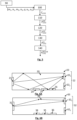
- the processing and calculation unit is also configured to implement the method for estimating the dissolved CO 2 content of the user's blood, the main steps of which are schematized on the figure 5 .
- the processing unit may include one or more microprocessors.
- FIG. 3A represents the conduit 14, which makes it possible to direct the gaseous mixture to the measuring chamber 20. Downstream of the measuring chamber 20, the gaseous mixture is led towards openings for evacuation 16, represented on the Fig. 3C . More specifically, conduit 14 is divided into two elementary ducts 14 1 and 14 2 , leading to the evacuation openings 16 arranged downstream of the outlets 14 s .
- the Figure 3B shows the measurement chamber 20, including in particular the photodetector 22.
- openings 36 are provided, allowing access of the ambient air to an auxiliary measuring chamber 30.
- the auxiliary measuring chamber 30 is isolated from the rest of the components of the main body, so that it is only exposed to the ambient air extending around the main body 2.
- the auxiliary measuring chamber does not receive transcutaneous CO 2 .
- the auxiliary measuring chamber 30 is optional. It makes it possible to refine the precision with which one can estimate the partial pressure of transcutaneous CO 2 in the gaseous mixture circulating through the measurement chamber 20.
- the transcutaneous CO 2 is admitted into the device through the transverse openings 11 made in the contact face 4, and opening into the collection chamber 10 (cf. arrow F 1 ).
- Ambient air is admitted through the openings 15 made in the side wall 5 (cf. arrows F 2 ).
- the gas mixture comprising the ambient air and the transcutaneous CO 2 spreads towards the measurement chamber 20 (cf. arrow F 3 ), through the conduit 14.
- the gas mixture then extends into the measurement chamber 20, between the infrared radiation source 21 and the photodetector 22 (cf. arrow F 4 ), before leaving the main body 2 (cf. arrows F 5 and F 6 ).
- the ambient air diffuses into the auxiliary measurement chamber 30 through the openings 36 (arrows F 10 ), and extends, by diffusion, through the auxiliary measurement chamber (arrows F 11 and arrows F 12 ).
- the processing and calculation unit 18 collects the measurements of the partial pressure of CO 2 in the measuring chamber 20 and in the auxiliary measuring chamber 30. From these measurements, the partial pressure of transcutaneous CO 2 is successively estimated, as well as the partial pressure of CO 2 in the blood, according to the stages schematized on the figure 5 .
- Step 100 determination of the CO 2 concentration in the measurement chamber 20.
- the measurement of the partial pressure of CO 2 in the measurement chamber 20 constitutes a particularly important step.
- FIG. 6A schematizes the measurement chamber 20. It defines a measurement volume extending between an infrared radiation source 21 and the photodetector 22. The source and the detector are components of the CO 2 sensor 23.
- the photodetector 22 includes a measurement channel 22 1 and a reference channel 22 2 .
- the measurement channel 22 1 is configured to detect the radiation having propagated through the measurement chamber 20, in a spectral absorption band which corresponds to the gaseous species which it is desired to analyze, in this case CO 2 .
- the reference channel 22 2 is configured to detect the radiation having propagated through the measurement chamber 20 in a reference spectral band, in which the absorption by the gaseous mixture is considered to be negligible.
- the absorption of the radiation by the water vapor can be considered equal. Otherwise, the humidity concentration is taken into account in the model, as described later. It is the same with the absorption of the air, which can be considered as equal to the two wavelengths.
- the measurement chamber 20 preferably comprises a temperature sensor 24 as well as a humidity sensor 25 and a pressure sensor 26.
- the auxiliary measurement chamber 30 preferably comprises an auxiliary temperature sensor 34 and an auxiliary humidity sensor 35 and an auxiliary pressure sensor 36.
- the concentration of CO 2 in the measurement chamber 20 can be estimated by a comparison, taking the form of a ratio, between the signals U( ⁇ 1 ) and U( ⁇ 2 ) respectively generated by the measurement photodetector and the reference photodetector, knowing that the ratio U 0 ⁇ 1 U 0 ⁇ 2 is determined by a calibration prior to the use of the device, and is considered to be constant during the use of the device.
- Expression (2) corresponds to the application of a linear model, the attenuation being considered as varying linearly as a function of the CO 2 concentration.
- the C H2O concentration is determined from the humidity sensor 25. It is therefore a quantity considered as known.
- Equation (8) gives two possible values of x, of which only one, generally the lowest, makes it possible to obtain a concentration C CO2 comprised within a range of predetermined values.
- the range of predetermined values corresponds to values which can be expected taking into account the intended application.
- Step 110 Determination of the partial pressure of CO 2 in the measuring chamber 20.
- Step 120 Determination of the partial pressure of CO 2 at the level of the collection chamber 10.
- Step 130 Determination of the transcutaneous CO 2 pressure.
- This step aims to determine the transcutaneous pressure of CO 2 from the partial pressure of CO 2 in the collection chamber 10.
- the air inlet through the side openings 15 must be taken into account.
- the collection chamber 10 includes a temperature sensor 17.
- the device also includes an ambient temperature sensor 34. When the device comprises an auxiliary measurement chamber 30, the ambient temperature sensor is preferably placed in the latter.
- the supply of CO 2 transported by the ambient air admitted through the side openings 15 is neglected.
- the assumption is then based on the assumption that the CO 2 circulating in the device is overwhelmingly transcutaneous CO 2 .
- the notation X( T x ) designates the fact that a quantity X is measured at the temperature T x
- the surface of the skin S skin placed opposite the device is defined by the geometry of the device.
- the concentration of CO 2 transported by the ambient air, admitted into the collection chamber 10 through the side openings 15, is also taken into account.
- the concentration of CO 2 can be predetermined, taking into account a predefined concentration, for example an average concentration of CO 2 in the air.
- the concentration of CO 2 in the ambient air is measured using the auxiliary measurement chamber 30, previously mentioned, or by another measurement method.
- the values m′ 1′ , n′ 1 , m′ 2 , n′ 2 , q′, u′ 1 and u′ 2 can be determined during a calibration phase, such as that described in step 90.
- CO 2 ct T ct g CO 2 ct / collar .
- S skin . H b air .
- CO 2 ct T ct g CO 2 ct / collar .
- Step 140 estimation of the partial pressure of CO 2 in the blood.
- the partial pressure of CO 2 in the collection chamber P CO 2 10 corresponds to the partial pressure of transcutaneous CO 2 P CO 2 ct .
- the partial pressure of CO 2 in the blood can be estimated by an empirical formula given in JW Severinghaus "The current status of transcutaneous blood gas analysis and monitoring", Blood Gas News, vol. 7, no. 2, pp 4-9, 1998 .
- P CO 2 blood 37 ° VS P CO 2 blood T ct ⁇ 4 e 0.046 T ct ⁇ 37 where T tc is a temperature measured by the temperature sensor 17'.
- the concentration VS CO 2 collar Due to the evacuation, by convection, of the CO 2 from the collection chamber, the concentration VS CO 2 collar is different from the concentration VS CO 2 collar , ⁇ .
- P CO 2 blood T ct T ct T 10 .
- g CO 2 blood / collar P CO 2 10 T 10 g CO 2 blood / collar is a correction factor allowing to correct the effect of dilution in the collection chamber as well as the effect of diffusion through the skin and the effect of the phase change from blood to air.
- g CO 2 blood / collar ⁇ skin blood .
- the CO 2 present in the ambient air admitted into the collection chamber through the transverse openings is taken into account.
- g CO 2 blood / collar ⁇ skin blood .
- T 10 is expressed in °C.
- Step 90 Model Calibration
- Step 100 requires having the parameters of the model m 1 , n 1 , m 2 , n 2 , and q as well as the values of the powers u 1 , u 2 .
- a calibration is implemented, aimed at determining the values of the parameters and of the powers.
- the calibration can be a supervised calibration, using a number N cal of calibration samples whose CO 2 content is known.
- the set of parameters ⁇ m 1 , n 1 , m 2 , n 2 , q , u 1 , u 2 ⁇ minimizing J can be determined by implementing a Levenberg Marquardt algorithm.
- the parameter ⁇ can be chosen a priori, or determined automatically by techniques of the cross-validation type.
- the Dilution Correction Factor g CO 2 ct / collar can be estimated by carrying out several learning acquisitions on human volunteers on which reference measurements either of the transcutaneous pressure or of the arterial pressure are carried out simultaneously with the measurement of the device during learning tests. We then estimate the average value of the factor g CO 2 ct / collar to be applied so that the estimated values of the transcutaneous pressure P CO 2 ct T ct approximate as closely as possible the measured reference values of the transcutaneous pressure or that the estimated values of the blood pressure P CO 2 blood 37 ° VS come as close as possible to the measured reference values of blood pressure.
- the nonlinear model explained in expression (3) was calibrated, according to step 90, by supplying the measuring chamber with the aid of a gas whose CO 2 concentration followed, during each test, concentration stages, respectively equal to 0, 0.2, 0.4, 0.8, 1.6 and 3.2 mol/m 3 . 12 tests were carried out, by varying the temperature T 20 of the measuring chamber 20, as well as the concentration in value of water C H2O , as well as the temperature T 10 in the collection chamber 10
- Table 1 shows the experimental parameters taken into account during each trial.
- Table 1 Essay C H2O (mol/ m3 ) T10 (°C) T 20 ( ° C) 1 0.126 30.1 30.3 2 0.301 39.7 32.0 3 0.365 37 32.4 4 0.364 39.7 31.8 5 0.691 40.1 32.2 6 0.428 30.2 30.2 7 0.623 37.1 32.0 8 0.898 40.1 31.5 9 0.863 37.2 31.6 10 0.609 30.3 30.3 11 0.753 30.1 30.2 12 1.160 37.1 32.3
- Table 2 presents the parameters of the model obtained following the minimization described in step 90.
- Table 2 Settings Model A Model B Model C ln() 1.08 0.99 1.07 m 1 0.29 0.29 0.29 u 1 0.61 0.59 0.57 # 1 0.051 0.048 0.044 m2 0.0040 0.0015 u 2 0.12 2.45 n2 0.065 0.00001 q 0.00028
- the ln() parameter corresponds to ln U 0 ⁇ 1 U 0 ⁇ 2 . This value is measured before carrying out the tests, in the absence of CO 2 in the measuring chamber.
- model C as described in connection with expression (3), has the lowest RMSE coefficient and the highest coefficient of determination. It is therefore optimal. It is also observed that taking the water vapor concentration into account (models B and C) improves performance.
- FIG. 7A shows, for each trial, the exact values of ⁇ ln U ⁇ 1 U ⁇ 2 measured (crosses) and the values of ⁇ ln U ⁇ 1 U ⁇ 2 calculated (circles) by implementing the model C. The consistency between the measured and calculated values is observed, which attests to the relevance of the model.
- the constants of the fluidic model it is also possible to perform a calibration using mixtures in a reference liquid such as water, for known CO 2 concentrations.
- the dilution of the CO 2 in order to produce the mixtures can be accelerated by using a bubbler and a mixer.
- Different techniques make it possible to control the concentration of CO 2 dissolved in a liquid, for example water, for example by using a dedicated probe, for example a submersible probe "CO2 Membrane/NDIR probe” marketed by AquaMS.
- the dissolved CO2 concentration can also be obtained by measuring the pH (hydrogen ion content) and the kH (carbonate ion content).
- the carbon dioxide released from the mixture is measured with the device as previously described.
- the concentration of dissolved carbon dioxide in the water is estimated.
- the model parameters are estimated so as to minimize the error between the estimated carbon dioxide concentration and the physical concentrations of the standard mixtures.
- Device 1 was applied against the forearm at the bend of the elbow of a healthy user undergoing a cardiopulmonary exercise test. According to this test, the user is placed on a bicycle and modulates his effort according to the pedaling speed. After a rest period, lasting 9 minutes, he performs 4 levels of 5 minutes, gradually increasing the pedaling speed. He then performs two recovery stages: one at slow speed, the other at rest.
- There figure 7B shows an evolution of the partial pressure of CO 2 P CO 2 10 in the collection chamber, by implementing steps 100 to 120 previously described. The measuring points are represented by dark crosses. The ordinate axis corresponds to the estimated partial pressure, while the abscissa axis corresponds to time.
- the measured values were smoothed either by a sliding average of width 100 s (curve a), or by a polynomial of order 3 (curve b).
- the smoothed values are consistent with the evolution of the partial pressure of CO 2 in the blood during a cardiopulmonary exercise following such a protocol.
Landscapes
- Health & Medical Sciences (AREA)
- Life Sciences & Earth Sciences (AREA)
- Physics & Mathematics (AREA)
- Pathology (AREA)
- General Health & Medical Sciences (AREA)
- Animal Behavior & Ethology (AREA)
- Public Health (AREA)
- Biomedical Technology (AREA)
- Heart & Thoracic Surgery (AREA)
- Medical Informatics (AREA)
- Molecular Biology (AREA)
- Surgery (AREA)
- Biophysics (AREA)
- Spectroscopy & Molecular Physics (AREA)
- Engineering & Computer Science (AREA)
- Veterinary Medicine (AREA)
- Optics & Photonics (AREA)
- Chemical & Material Sciences (AREA)
- Analytical Chemistry (AREA)
- Biochemistry (AREA)
- General Physics & Mathematics (AREA)
- Immunology (AREA)
- Measurement Of The Respiration, Hearing Ability, Form, And Blood Characteristics Of Living Organisms (AREA)
- Measuring And Recording Apparatus For Diagnosis (AREA)
Claims (15)
- Messvorrichtung (1) zur Anordnung auf der Haut eines Benutzers, wobei der Benutzer ein Mensch oder ein Tier ist, wobei sich die Vorrichtung zwischen einer Kontaktfläche (4) zur Applikation auf der Haut des Benutzers und einem distalen Ende (6) erstreckt, wobei die Vorrichtung eine Seitenwand (5) aufweist, die sich zwischen der Kontaktfläche und dem distalen Ende erstreckt, wobei die Vorrichtung Folgendes aufweist:- an der Kontaktfläche wenigstens eine Öffnung (11), die dazu ausgebildet ist, ein transkutanes Gas von Interesse zu sammeln, das durch die Haut abgegeben wird, wobei die Öffnung durch die Kontaktfläche hindurch ausgebildet ist;- eine Sammelkammer (10), die sich zwischen der Kontaktfläche und einer Messkammer (20) erstreckt;- einen Gassensor (23), der in der Messkammer angeordnet ist und dazu ausgebildet ist, eine Konzentration von Gas von Interesse zu messen, das in der Messkammer strömt;- eine Verarbeitungs- und Recheneinheit (18), die dazu ausgebildet ist, einen Gehalt an Gas von Interesse im Körper des Benutzers anhand der Messung aus dem Gassensor zu schätzen;- eine Wärmequelle, die dazu ausgebildet ist, die Kontaktfläche auf eine Temperatur höher als 37 °C zu bringen;wobei die Vorrichtung dadurch gekennzeichnet ist, dass sie Folgendes aufweist:- eine Öffnung (15), die einen Lufteinlass bildet, die durch die Seitenwand (5) hindurch vorgesehen ist, die dazu ausgebildet ist, Umgebungsluft in die Sammelkammer (10) einzulassen;so dass sich unter der Einwirkung der Temperatur, die von der Wärmequelle erzeugt wird, eine Luftkonvektionsströmung einstellt, wobei die Luft, die durch die Seitenwand in die Sammelkammer (10) eingelassen wird, das transkutane Gas von Interesse zur Messkammer (20) mitnimmt, wobei die Luft und das transkutane Gas von Interesse ein Gasgemisch bilden, das sich in der Messkammer erstreckt.
- Vorrichtung nach Anspruch 1, wobei das Gas von Interesse Kohlendioxid ist.
- Vorrichtung nach einem der vorhergehenden Ansprüche, aufweisend einen Feuchtesensor (25) zur Bestimmung einer Feuchtigkeit in der Messkammer (20), wobei die Verarbeitungs- und Recheneinheit (18) dazu ausgebildet ist, die Feuchtigkeit in der Messkammer (20) zu berücksichtigen, um eine Konzentration von Gas von Interesse in der Messkammer zu schätzen.
- Vorrichtung nach einem der vorhergehenden Ansprüche, aufweisend einen Drucksensor (26) zur Bestimmung eines Drucks in der Messkammer (20), wobei die Verarbeitungs- und Recheneinheit (18) dazu ausgebildet ist, den Druck in der Messkammer zu berücksichtigen, um einen Partialdruck von Gas von Interesse in der Sammelkammer (10) zu schätzen.
- Vorrichtung nach einem der vorhergehenden Ansprüche, wobei der Gassensor (23) ein optischer Sensor ist, der eine Infrarotstrahlungsquelle (21) und einen Photodetektor (22) aufweist, wobei die Infrarotstrahlungsquelle und der Photodetektor so angeordnet sind, dass das Gasgemisch in der Messkammer (20) zwischen der Infrarotstrahlungsquelle (21) und dem Photodetektor (22) strömt, wobei der Photodetektor zwei Messkanäle (221, 222) aufweist, die dazu ausgebildet sind, jeweils eine Infrarotstrahlung zu messen, die von der Infrarotstrahlungsquelle (21) abgegeben wird und sich durch die Messkammer ausgebreitet hat, in:- einem Messspektralband (λ1), das einem Absorptionsspektralband des Gases von Interesse entspricht;- einem Referenzspektralband (λ2), das als nicht durch das Gas von Interesse absorbiert erachtet wird.
- Vorrichtung nach einem der vorhergehenden Ansprüche, aufweisend:- eine Hilfsmesskammer (30), die dazu ausgebildet ist, von der Umgebungsluft eingenommen zu sein, die sich um die Vorrichtung (1) herum erstreckt;- einen Hilfssensor für Gas von Interesse (33), der in der Hilfsmesskammer angeordnet ist und dazu ausgebildet ist, eine Konzentration von Gas von Interesse in der Umgebungsluft zu messen, die die Hilfsmesskammer einnimmt;wobei die Verarbeitungs- und Recheneinheit (18) dazu ausgebildet ist, die Messung des Hilfssensors zu berücksichtigen, um den Gehalt an Gas von Interesse im Körper des Benutzers zu schätzen.
- Vorrichtung nach Anspruch 6, wobei der Hilfssensor für Gas von Interesse (33) ein optischer Sensor ist, der eine Hilfs-Infrarotstrahlungsquelle (31) und einen Hilfsphotodetektor (32) aufweist, wobei die Hilfs-Infrarotstrahlungsquelle und der Hilfsphotodetektor so angeordnet sind, dass sich die Umgebungsluft in der Hilfsmesskammer (30) zwischen der Hilfs-Infrarotstrahlungsquelle und dem Hilfsphotodetektor (32) erstreckt, wobei der Hilfsphotodetektor zwei Messkanäle aufweist, die dazu ausgebildet sind, jeweils eine Infrarotstrahlung zu messen, die von der Hilfs-Infrarotstrahlungsquelle abgegeben wird und sich durch die Hilfsmesskammer ausgebreitet hat, in:- einem Messspektralband (λ1), das einem Absorptionsspektralband des Gases von Interesse entspricht;- einem Referenzspektralband (λ2), das als nicht durch das Gas von Interesse absorbiert erachtet wird.
- Vorrichtung nach einem der vorhergehenden Ansprüche, aufweisend:- einen Sensor für den Druck (36) der Umgebungsluft, wobei sich die Umgebungsluft um die Vorrichtung herum erstreckt;- und/oder einen Sensor für die Temperatur (34) der Umgebungsluft;- und/oder einen Drucksensor (19) in der Sammelkammer;- und/oder einen Temperatursensor (17) in der Sammelkammer;- und/oder einen Temperatursensor (17'), der dazu ausgebildet ist, eine Temperatur der Haut zu messen;- und/oder einen Temperatursensor (24) in der Messkammer.
- Verfahren zur Schätzung eines Gehalts an Gas von Interesse im Blut eines Benutzers mithilfe einer Vorrichtung (1) nach einem der vorhergehenden Ansprüche, wobei die Vorrichtung so appliziert wird, dass die Kontaktfläche (4) an der Haut des Benutzers angeordnet ist, wobei das Verfahren ein Erwärmen der Kontaktfläche sowie ein Einlassen von Umgebungsluft durch die Seitenwand (5) der Vorrichtung aufweist, wobei das Verfahren Folgendes aufweist:a) ein Schätzen einer Konzentration von Gas von Interesse in der Messkammer (20);b) anhand der Konzentration von Gas von Interesse, die aus Schritt a) hervorgeht, Berechnen eines Partialdrucks von Gas von Interesse in der Sammelkammer (10);c) anhand des Partialdrucks von Gas von Interesse in der Sammelkammer (10), der aus Schritt b) hervorgeht, Schätzen eines Partialdrucks von Gas von Interesse, das im Blut des Benutzers gelöst ist.
- Verfahren nach Anspruch 9, wobei der Schritt c) die folgenden Unterschritte aufweist:(i) anhand des Partialdrucks von Gas von Interesse in der Sammelkammer, der aus Schritt b) hervorgeht, Schätzen eines Partialdrucks von transkutanem Gas von Interesse, das durch die Haut des Benutzers hindurch diffundiert ist;(ii) anhand des Partialdrucks von transkutanem Gas von Interesse, der aus Schritt (i) hervorgeht, Schätzen eines Partialdrucks von Gas von Interesse, das im Blut des Benutzers gelöst ist.
- Verfahren nach einem der Ansprüche 9 bis 10, ebenfalls aufweisend ein Messen einer Konzentration von Gas von Interesse in der Umgebungsluft, wobei die so gemessene Konzentration im Schritt c) berücksichtigt wird.
- Verfahren nach einem der Ansprüche 9 bis 11, aufweisend ein Messen eines Drucks der Umgebungsluft, wobei der Druck der Umgebungsluft im Schritt c) berücksichtigt wird.
- Verfahren nach einem der Ansprüche 9 bis 12, wobei der Schritt a) mithilfe eines Gassensors (23) durchgeführt wird, der in der Messkammer (20) angeordnet ist und von einer Infrarotstrahlungsquelle (21) und von einem Photodetektor (22) gebildet ist, der zwei Messkanäle (221, 222) aufweist, die dazu ausgebildet sind, jeweils eine Infrarotstrahlung zu messen, die von der Infrarotstrahlungsquelle abgegeben wird und sich durch die Messkammer (20) ausgebreitet hat, in:- einem Messspektralband (λ1), das einem Absorptionsspektralband des Gases von Interesse entspricht;- einem Referenzspektralband (λ2), das als nicht durch das Gas von Interesse absorbiert erachtet wird;
und wobei der Schritt a) Folgendes aufweist- ein Vergleichen von Signalen (U(λ1), U(λ2)), die jeweils von den zwei Messkanälen erzeugt werden;- ein Lösen eines Polynoms zweiten Grades unter Verwendung des Vergleichs sowie vorbestimmter Parameter, um die Konzentration von Gas von Interesse in der Messkammer zu schätzen. - Verfahren nach Anspruch 13, wobei die Wurzel des Polynoms eine nichtganzzahlige Potenz der Konzentration von Gas von Interesse in der Messkammer (20) ist.
- Verfahren nach einem der Ansprüche 9 bis 14, wobei das Gas von Interesse das Kohlendioxid ist.
Applications Claiming Priority (2)
| Application Number | Priority Date | Filing Date | Title |
|---|---|---|---|
| FR1906142A FR3096885B1 (fr) | 2019-06-09 | 2019-06-09 | Dispositif portable d'estimation de la pression partielle de gaz sanguin |
| PCT/EP2020/065523 WO2020249466A1 (fr) | 2019-06-09 | 2020-06-04 | Dispositif portable d'estimation de la pression partielle de gaz sanguin |
Publications (2)
| Publication Number | Publication Date |
|---|---|
| EP3979911A1 EP3979911A1 (de) | 2022-04-13 |
| EP3979911B1 true EP3979911B1 (de) | 2023-07-26 |
Family
ID=68987753
Family Applications (1)
| Application Number | Title | Priority Date | Filing Date |
|---|---|---|---|
| EP20732155.5A Active EP3979911B1 (de) | 2019-06-09 | 2020-06-04 | Tragbare vorrichtung zur bestimmung des partialdrucks von blutgas |
Country Status (4)
| Country | Link |
|---|---|
| US (1) | US12507919B2 (de) |
| EP (1) | EP3979911B1 (de) |
| FR (1) | FR3096885B1 (de) |
| WO (1) | WO2020249466A1 (de) |
Families Citing this family (6)
| Publication number | Priority date | Publication date | Assignee | Title |
|---|---|---|---|---|
| US11766000B2 (en) * | 2021-06-28 | 2023-09-26 | Haier Us Appliance Solutions, Inc. | Gas sensing assembly for an indoor garden center |
| EP4577112A1 (de) | 2022-08-28 | 2025-07-02 | Commissariat à l'Energie Atomique et aux Energies Alternatives | Verfahren zur schätzung einer konzentration eines von einem medium emittierten gases |
| FR3139001A1 (fr) | 2022-08-28 | 2024-03-01 | Commissariat à l'Energie Atomique et aux Energies Alternatives | Dispositif portable d'estimation d’une concentration de gaz dégagé par un milieu. |
| FR3138999A1 (fr) | 2022-08-28 | 2024-03-01 | Commissariat A L'energie Atomique Et Aux Energies Alternatives | Procédé d’estimation d’une concentration de gaz dégagé par un milieu |
| CN115644847A (zh) * | 2022-11-07 | 2023-01-31 | 深圳中国计量科学研究院技术创新研究院 | 一种经皮氧气、二氧化碳检测装置 |
| FR3153659A1 (fr) * | 2023-09-29 | 2025-04-04 | Commissariat A L'energie Atomique Et Aux Energies Alternatives | Dispositif portable de détection d’un gaz émis par un objet |
Family Cites Families (9)
| Publication number | Priority date | Publication date | Assignee | Title |
|---|---|---|---|---|
| US3987303A (en) * | 1975-02-06 | 1976-10-19 | Hewlett-Packard Company | Medical-analytical gas detector |
| SE7811708L (sv) * | 1977-11-15 | 1979-05-16 | Medishield Corp Ltd | Transkutan sond |
| EP0267978B1 (de) * | 1986-11-17 | 1991-08-28 | PPG Hellige GmbH | Kombinationssensor zur transcutanen Erfassung von Sauerstoff und Kohlendioxid im Blut |
| US20010034479A1 (en) * | 2000-04-19 | 2001-10-25 | Ring Lawrence S. | Optically based transcutaneous blood gas sensor |
| ITMI20070110A1 (it) * | 2007-01-25 | 2008-07-26 | Elio Scarano | Sensore ed apparecchio per l'analisi dei gas presenti nel sangue |
| US8527023B2 (en) * | 2007-04-27 | 2013-09-03 | Sentec Ag | Device and method for transcutaneous determination of blood gases |
| WO2012045047A2 (en) * | 2010-09-30 | 2012-04-05 | University Of Maryland Baltimore County | Non-invasive analyte sensing and monitoring system and method |
| WO2014111779A1 (en) * | 2013-01-16 | 2014-07-24 | Koninklijke Philips N.V. | Sensor for determining gas concentration |
| WO2015010709A1 (en) * | 2013-07-22 | 2015-01-29 | Sentec Ag | Sensor for detection of gas and method for detection of gas |
-
2019
- 2019-06-09 FR FR1906142A patent/FR3096885B1/fr not_active Expired - Fee Related
-
2020
- 2020-06-04 WO PCT/EP2020/065523 patent/WO2020249466A1/fr not_active Ceased
- 2020-06-04 EP EP20732155.5A patent/EP3979911B1/de active Active
- 2020-06-04 US US17/617,526 patent/US12507919B2/en active Active
Also Published As
| Publication number | Publication date |
|---|---|
| EP3979911A1 (de) | 2022-04-13 |
| FR3096885B1 (fr) | 2021-06-18 |
| US12507919B2 (en) | 2025-12-30 |
| FR3096885A1 (fr) | 2020-12-11 |
| US20220248992A1 (en) | 2022-08-11 |
| WO2020249466A1 (fr) | 2020-12-17 |
Similar Documents
| Publication | Publication Date | Title |
|---|---|---|
| WO2020249466A1 (fr) | Dispositif portable d'estimation de la pression partielle de gaz sanguin | |
| US7438855B2 (en) | Apparatus for measuring glucose concentration | |
| US7004909B1 (en) | Diagnostic method for high sensitivity detection of component concentrations in human gas emissions | |
| Vincent et al. | A low cost MEMS based NDIR system for the monitoring of carbon dioxide in breath analysis at ppm levels | |
| US20150289782A1 (en) | Portable breath volatile organic compounds analyser and corresponding unit | |
| TW421713B (en) | Stable isotope measurement method and apparatus by spectroscopy | |
| EP0877925B1 (de) | Verfahren und vorrichtung zur multispektralen analyse bei der nichtinvasiven infrarot-spektroskopie | |
| FR2905762A1 (fr) | Systeme et procede de detection et d'analyse d'au moins une substance volatile dans des echantillons d'haleine d'un sujet | |
| CN106574896A (zh) | 气体混合物的组分的浓度的测量装置和测量方法 | |
| US20110295140A1 (en) | Method and Apparatus for Measuring Trace Levels of CO in Human Breath Using Cavity Enhanced, Mid-Infared Absorption Spectroscopy | |
| US20150211990A1 (en) | Diagnostic Method for High Sensitivity Detection of Component Concentrations in Human Gas Emission | |
| US20030208133A1 (en) | Breath ketone analyzer | |
| FR2614990A1 (fr) | Analyses de fluide par infrarouge, en particulier un detecteur de gaz carbonique | |
| Lewicki et al. | Real time ammonia detection in exhaled human breath using a distributed feedback quantum cascade laser based sensor | |
| EP3535583B1 (de) | Nichtinvasive photonische erfassung zur überwachung von diabetes | |
| JPWO2015137074A1 (ja) | 成分測定装置、方法及びプログラム | |
| Li et al. | A mid-infrared exhaled carbon dioxide isotope detection system based on 4.35 μm quantum cascade laser | |
| Glöckler et al. | iHWG-MOX: a hybrid breath analysis system via the combination of substrate-integrated hollow waveguide infrared spectroscopy with metal oxide gas sensors | |
| US20130011872A1 (en) | Stable isotopic biomarker measurement for the detection of cancer and the determination of efficacy of treatment in diagnosed cancer patients | |
| WO2014132077A1 (en) | Apparatus and method of breath volatile organic compound analysis and calibration method | |
| WO2024046930A1 (fr) | Procédé d'estimation d'une concentration de gaz dégagé par un milieu | |
| EP4281756B1 (de) | Verfahren zur kalibrierung eines gassensors und verfahren zur messung eines gases mit der kalibrierung | |
| KR100883153B1 (ko) | 혈당치의 비침습 측정 장치 | |
| Tittel et al. | Real time detection of exhaled human breath using quantum cascade laser based sensor technology | |
| RU216708U1 (ru) | Оптический инфракрасный модуль для селективного определения концентрации аммиака в потоке выдыхаемого воздуха |
Legal Events
| Date | Code | Title | Description |
|---|---|---|---|
| STAA | Information on the status of an ep patent application or granted ep patent |
Free format text: STATUS: UNKNOWN |
|
| STAA | Information on the status of an ep patent application or granted ep patent |
Free format text: STATUS: THE INTERNATIONAL PUBLICATION HAS BEEN MADE |
|
| PUAI | Public reference made under article 153(3) epc to a published international application that has entered the european phase |
Free format text: ORIGINAL CODE: 0009012 |
|
| STAA | Information on the status of an ep patent application or granted ep patent |
Free format text: STATUS: REQUEST FOR EXAMINATION WAS MADE |
|
| 17P | Request for examination filed |
Effective date: 20211206 |
|
| AK | Designated contracting states |
Kind code of ref document: A1 Designated state(s): AL AT BE BG CH CY CZ DE DK EE ES FI FR GB GR HR HU IE IS IT LI LT LU LV MC MK MT NL NO PL PT RO RS SE SI SK SM TR |
|
| DAV | Request for validation of the european patent (deleted) | ||
| DAX | Request for extension of the european patent (deleted) | ||
| GRAP | Despatch of communication of intention to grant a patent |
Free format text: ORIGINAL CODE: EPIDOSNIGR1 |
|
| STAA | Information on the status of an ep patent application or granted ep patent |
Free format text: STATUS: GRANT OF PATENT IS INTENDED |
|
| INTG | Intention to grant announced |
Effective date: 20230119 |
|
| GRAS | Grant fee paid |
Free format text: ORIGINAL CODE: EPIDOSNIGR3 |
|
| GRAA | (expected) grant |
Free format text: ORIGINAL CODE: 0009210 |
|
| STAA | Information on the status of an ep patent application or granted ep patent |
Free format text: STATUS: THE PATENT HAS BEEN GRANTED |
|
| AK | Designated contracting states |
Kind code of ref document: B1 Designated state(s): AL AT BE BG CH CY CZ DE DK EE ES FI FR GB GR HR HU IE IS IT LI LT LU LV MC MK MT NL NO PL PT RO RS SE SI SK SM TR |
|
| REG | Reference to a national code |
Ref country code: CH Ref legal event code: EP |
|
| REG | Reference to a national code |
Ref country code: IE Ref legal event code: FG4D Free format text: LANGUAGE OF EP DOCUMENT: FRENCH |
|
| REG | Reference to a national code |
Ref country code: DE Ref legal event code: R096 Ref document number: 602020014480 Country of ref document: DE |
|
| REG | Reference to a national code |
Ref country code: LT Ref legal event code: MG9D |
|
| REG | Reference to a national code |
Ref country code: NL Ref legal event code: MP Effective date: 20230726 |
|
| REG | Reference to a national code |
Ref country code: AT Ref legal event code: MK05 Ref document number: 1590980 Country of ref document: AT Kind code of ref document: T Effective date: 20230726 |
|
| PG25 | Lapsed in a contracting state [announced via postgrant information from national office to epo] |
Ref country code: NL Free format text: LAPSE BECAUSE OF FAILURE TO SUBMIT A TRANSLATION OF THE DESCRIPTION OR TO PAY THE FEE WITHIN THE PRESCRIBED TIME-LIMIT Effective date: 20230726 |
|
| PG25 | Lapsed in a contracting state [announced via postgrant information from national office to epo] |
Ref country code: GR Free format text: LAPSE BECAUSE OF FAILURE TO SUBMIT A TRANSLATION OF THE DESCRIPTION OR TO PAY THE FEE WITHIN THE PRESCRIBED TIME-LIMIT Effective date: 20231027 |
|
| PG25 | Lapsed in a contracting state [announced via postgrant information from national office to epo] |
Ref country code: IS Free format text: LAPSE BECAUSE OF FAILURE TO SUBMIT A TRANSLATION OF THE DESCRIPTION OR TO PAY THE FEE WITHIN THE PRESCRIBED TIME-LIMIT Effective date: 20231126 |
|
| PG25 | Lapsed in a contracting state [announced via postgrant information from national office to epo] |
Ref country code: SE Free format text: LAPSE BECAUSE OF FAILURE TO SUBMIT A TRANSLATION OF THE DESCRIPTION OR TO PAY THE FEE WITHIN THE PRESCRIBED TIME-LIMIT Effective date: 20230726 Ref country code: RS Free format text: LAPSE BECAUSE OF FAILURE TO SUBMIT A TRANSLATION OF THE DESCRIPTION OR TO PAY THE FEE WITHIN THE PRESCRIBED TIME-LIMIT Effective date: 20230726 Ref country code: PT Free format text: LAPSE BECAUSE OF FAILURE TO SUBMIT A TRANSLATION OF THE DESCRIPTION OR TO PAY THE FEE WITHIN THE PRESCRIBED TIME-LIMIT Effective date: 20231127 Ref country code: NO Free format text: LAPSE BECAUSE OF FAILURE TO SUBMIT A TRANSLATION OF THE DESCRIPTION OR TO PAY THE FEE WITHIN THE PRESCRIBED TIME-LIMIT Effective date: 20231026 Ref country code: LV Free format text: LAPSE BECAUSE OF FAILURE TO SUBMIT A TRANSLATION OF THE DESCRIPTION OR TO PAY THE FEE WITHIN THE PRESCRIBED TIME-LIMIT Effective date: 20230726 Ref country code: LT Free format text: LAPSE BECAUSE OF FAILURE TO SUBMIT A TRANSLATION OF THE DESCRIPTION OR TO PAY THE FEE WITHIN THE PRESCRIBED TIME-LIMIT Effective date: 20230726 Ref country code: IS Free format text: LAPSE BECAUSE OF FAILURE TO SUBMIT A TRANSLATION OF THE DESCRIPTION OR TO PAY THE FEE WITHIN THE PRESCRIBED TIME-LIMIT Effective date: 20231126 Ref country code: HR Free format text: LAPSE BECAUSE OF FAILURE TO SUBMIT A TRANSLATION OF THE DESCRIPTION OR TO PAY THE FEE WITHIN THE PRESCRIBED TIME-LIMIT Effective date: 20230726 Ref country code: GR Free format text: LAPSE BECAUSE OF FAILURE TO SUBMIT A TRANSLATION OF THE DESCRIPTION OR TO PAY THE FEE WITHIN THE PRESCRIBED TIME-LIMIT Effective date: 20231027 Ref country code: FI Free format text: LAPSE BECAUSE OF FAILURE TO SUBMIT A TRANSLATION OF THE DESCRIPTION OR TO PAY THE FEE WITHIN THE PRESCRIBED TIME-LIMIT Effective date: 20230726 Ref country code: AT Free format text: LAPSE BECAUSE OF FAILURE TO SUBMIT A TRANSLATION OF THE DESCRIPTION OR TO PAY THE FEE WITHIN THE PRESCRIBED TIME-LIMIT Effective date: 20230726 |
|
| PG25 | Lapsed in a contracting state [announced via postgrant information from national office to epo] |
Ref country code: PL Free format text: LAPSE BECAUSE OF FAILURE TO SUBMIT A TRANSLATION OF THE DESCRIPTION OR TO PAY THE FEE WITHIN THE PRESCRIBED TIME-LIMIT Effective date: 20230726 |
|
| PG25 | Lapsed in a contracting state [announced via postgrant information from national office to epo] |
Ref country code: ES Free format text: LAPSE BECAUSE OF FAILURE TO SUBMIT A TRANSLATION OF THE DESCRIPTION OR TO PAY THE FEE WITHIN THE PRESCRIBED TIME-LIMIT Effective date: 20230726 |
|
| REG | Reference to a national code |
Ref country code: DE Ref legal event code: R097 Ref document number: 602020014480 Country of ref document: DE |
|
| PG25 | Lapsed in a contracting state [announced via postgrant information from national office to epo] |
Ref country code: SM Free format text: LAPSE BECAUSE OF FAILURE TO SUBMIT A TRANSLATION OF THE DESCRIPTION OR TO PAY THE FEE WITHIN THE PRESCRIBED TIME-LIMIT Effective date: 20230726 Ref country code: RO Free format text: LAPSE BECAUSE OF FAILURE TO SUBMIT A TRANSLATION OF THE DESCRIPTION OR TO PAY THE FEE WITHIN THE PRESCRIBED TIME-LIMIT Effective date: 20230726 Ref country code: ES Free format text: LAPSE BECAUSE OF FAILURE TO SUBMIT A TRANSLATION OF THE DESCRIPTION OR TO PAY THE FEE WITHIN THE PRESCRIBED TIME-LIMIT Effective date: 20230726 Ref country code: EE Free format text: LAPSE BECAUSE OF FAILURE TO SUBMIT A TRANSLATION OF THE DESCRIPTION OR TO PAY THE FEE WITHIN THE PRESCRIBED TIME-LIMIT Effective date: 20230726 Ref country code: DK Free format text: LAPSE BECAUSE OF FAILURE TO SUBMIT A TRANSLATION OF THE DESCRIPTION OR TO PAY THE FEE WITHIN THE PRESCRIBED TIME-LIMIT Effective date: 20230726 Ref country code: CZ Free format text: LAPSE BECAUSE OF FAILURE TO SUBMIT A TRANSLATION OF THE DESCRIPTION OR TO PAY THE FEE WITHIN THE PRESCRIBED TIME-LIMIT Effective date: 20230726 Ref country code: SK Free format text: LAPSE BECAUSE OF FAILURE TO SUBMIT A TRANSLATION OF THE DESCRIPTION OR TO PAY THE FEE WITHIN THE PRESCRIBED TIME-LIMIT Effective date: 20230726 |
|
| PG25 | Lapsed in a contracting state [announced via postgrant information from national office to epo] |
Ref country code: IT Free format text: LAPSE BECAUSE OF FAILURE TO SUBMIT A TRANSLATION OF THE DESCRIPTION OR TO PAY THE FEE WITHIN THE PRESCRIBED TIME-LIMIT Effective date: 20230726 |
|
| PLBE | No opposition filed within time limit |
Free format text: ORIGINAL CODE: 0009261 |
|
| STAA | Information on the status of an ep patent application or granted ep patent |
Free format text: STATUS: NO OPPOSITION FILED WITHIN TIME LIMIT |
|
| 26N | No opposition filed |
Effective date: 20240429 |
|
| PG25 | Lapsed in a contracting state [announced via postgrant information from national office to epo] |
Ref country code: SI Free format text: LAPSE BECAUSE OF FAILURE TO SUBMIT A TRANSLATION OF THE DESCRIPTION OR TO PAY THE FEE WITHIN THE PRESCRIBED TIME-LIMIT Effective date: 20230726 |
|
| PG25 | Lapsed in a contracting state [announced via postgrant information from national office to epo] |
Ref country code: BG Free format text: LAPSE BECAUSE OF FAILURE TO SUBMIT A TRANSLATION OF THE DESCRIPTION OR TO PAY THE FEE WITHIN THE PRESCRIBED TIME-LIMIT Effective date: 20230726 |
|
| PG25 | Lapsed in a contracting state [announced via postgrant information from national office to epo] |
Ref country code: BG Free format text: LAPSE BECAUSE OF FAILURE TO SUBMIT A TRANSLATION OF THE DESCRIPTION OR TO PAY THE FEE WITHIN THE PRESCRIBED TIME-LIMIT Effective date: 20230726 |
|
| PG25 | Lapsed in a contracting state [announced via postgrant information from national office to epo] |
Ref country code: MC Free format text: LAPSE BECAUSE OF FAILURE TO SUBMIT A TRANSLATION OF THE DESCRIPTION OR TO PAY THE FEE WITHIN THE PRESCRIBED TIME-LIMIT Effective date: 20230726 |
|
| REG | Reference to a national code |
Ref country code: CH Ref legal event code: PL |
|
| PG25 | Lapsed in a contracting state [announced via postgrant information from national office to epo] |
Ref country code: LU Free format text: LAPSE BECAUSE OF NON-PAYMENT OF DUE FEES Effective date: 20240604 |
|
| PG25 | Lapsed in a contracting state [announced via postgrant information from national office to epo] |
Ref country code: IE Free format text: LAPSE BECAUSE OF NON-PAYMENT OF DUE FEES Effective date: 20240604 |
|
| PG25 | Lapsed in a contracting state [announced via postgrant information from national office to epo] |
Ref country code: BE Free format text: LAPSE BECAUSE OF NON-PAYMENT OF DUE FEES Effective date: 20240630 Ref country code: CH Free format text: LAPSE BECAUSE OF NON-PAYMENT OF DUE FEES Effective date: 20240630 |
|
| REG | Reference to a national code |
Ref country code: BE Ref legal event code: MM Effective date: 20240630 |
|
| PGFP | Annual fee paid to national office [announced via postgrant information from national office to epo] |
Ref country code: DE Payment date: 20250618 Year of fee payment: 6 |
|
| PGFP | Annual fee paid to national office [announced via postgrant information from national office to epo] |
Ref country code: GB Payment date: 20250625 Year of fee payment: 6 |
|
| PGFP | Annual fee paid to national office [announced via postgrant information from national office to epo] |
Ref country code: FR Payment date: 20250623 Year of fee payment: 6 |
|
| PG25 | Lapsed in a contracting state [announced via postgrant information from national office to epo] |
Ref country code: CY Free format text: LAPSE BECAUSE OF FAILURE TO SUBMIT A TRANSLATION OF THE DESCRIPTION OR TO PAY THE FEE WITHIN THE PRESCRIBED TIME-LIMIT; INVALID AB INITIO Effective date: 20200604 |
|
| PG25 | Lapsed in a contracting state [announced via postgrant information from national office to epo] |
Ref country code: HU Free format text: LAPSE BECAUSE OF FAILURE TO SUBMIT A TRANSLATION OF THE DESCRIPTION OR TO PAY THE FEE WITHIN THE PRESCRIBED TIME-LIMIT; INVALID AB INITIO Effective date: 20200604 |