EP3979780B1 - Verfahren zum betrieb von bodenbearbeitungsgeräten - Google Patents
Verfahren zum betrieb von bodenbearbeitungsgeräten Download PDFInfo
- Publication number
- EP3979780B1 EP3979780B1 EP20716212.4A EP20716212A EP3979780B1 EP 3979780 B1 EP3979780 B1 EP 3979780B1 EP 20716212 A EP20716212 A EP 20716212A EP 3979780 B1 EP3979780 B1 EP 3979780B1
- Authority
- EP
- European Patent Office
- Prior art keywords
- tillage implement
- map
- boundaries
- computer
- adjusting
- Prior art date
- Legal status (The legal status is an assumption and is not a legal conclusion. Google has not performed a legal analysis and makes no representation as to the accuracy of the status listed.)
- Active
Links
Images

Classifications
-
- A—HUMAN NECESSITIES
- A01—AGRICULTURE; FORESTRY; ANIMAL HUSBANDRY; HUNTING; TRAPPING; FISHING
- A01B—SOIL WORKING IN AGRICULTURE OR FORESTRY; PARTS, DETAILS, OR ACCESSORIES OF AGRICULTURAL MACHINES OR IMPLEMENTS, IN GENERAL
- A01B63/00—Lifting or adjusting devices or arrangements for agricultural machines or implements
- A01B63/14—Lifting or adjusting devices or arrangements for agricultural machines or implements for implements drawn by animals or tractors
-
- A—HUMAN NECESSITIES
- A01—AGRICULTURE; FORESTRY; ANIMAL HUSBANDRY; HUNTING; TRAPPING; FISHING
- A01B—SOIL WORKING IN AGRICULTURE OR FORESTRY; PARTS, DETAILS, OR ACCESSORIES OF AGRICULTURAL MACHINES OR IMPLEMENTS, IN GENERAL
- A01B29/00—Rollers
- A01B29/04—Rollers with non-smooth surface formed of rotatably-mounted rings or discs or with projections or ribs on the roller body; Land packers
-
- A—HUMAN NECESSITIES
- A01—AGRICULTURE; FORESTRY; ANIMAL HUSBANDRY; HUNTING; TRAPPING; FISHING
- A01B—SOIL WORKING IN AGRICULTURE OR FORESTRY; PARTS, DETAILS, OR ACCESSORIES OF AGRICULTURAL MACHINES OR IMPLEMENTS, IN GENERAL
- A01B63/00—Lifting or adjusting devices or arrangements for agricultural machines or implements
- A01B63/002—Devices for adjusting or regulating the position of tools or wheels
- A01B63/008—Vertical adjustment of tools
-
- A—HUMAN NECESSITIES
- A01—AGRICULTURE; FORESTRY; ANIMAL HUSBANDRY; HUNTING; TRAPPING; FISHING
- A01B—SOIL WORKING IN AGRICULTURE OR FORESTRY; PARTS, DETAILS, OR ACCESSORIES OF AGRICULTURAL MACHINES OR IMPLEMENTS, IN GENERAL
- A01B79/00—Methods for working soil
- A01B79/005—Precision agriculture
-
- A—HUMAN NECESSITIES
- A01—AGRICULTURE; FORESTRY; ANIMAL HUSBANDRY; HUNTING; TRAPPING; FISHING
- A01B—SOIL WORKING IN AGRICULTURE OR FORESTRY; PARTS, DETAILS, OR ACCESSORIES OF AGRICULTURAL MACHINES OR IMPLEMENTS, IN GENERAL
- A01B49/00—Combined machines
- A01B49/02—Combined machines with two or more soil-working tools of different kind
- A01B49/027—Combined machines with two or more soil-working tools of different kind with a rotating, soil working support element, e.g. a roller
Definitions
- Embodiments of the present disclosure relate to working agricultural fields. More particularly, embodiments of the present disclosure relate to methods for adjusting tillage implements based on maps.
- Crop yields are affected by a variety of factors, such as seed placement, soil quality, weather, irrigation, and nutrient applications. Soil compaction affects how seeds are placed, as well as how water and fertilizer permeates the soil. Typically, a field includes a layer of soil below the surface that is harder and denser than soil above or below it. This layer is referred to in the art as a "compaction layer.” The compaction layer is generally less permeable to air and water than the surrounding soil. Roots forming from seeds planted above the compaction layer may grow downward toward the compaction layer, and may then tend to grow outward if they cannot break through the compaction layer. The depth of the compaction layer typically varies throughout a field.
- U.S. Patent 6,041,582 "System for Recording Soil Conditions" discloses a system in which sensors are used to detect load on a soil working tool due to soil compaction.
- a location signal generation circuit generates signals relating to the location at which the force signal is sampled.
- the force data is correlated with the locations at which the force was sampled.
- the correlated data is saved and may be used to generate a field map indicating soil condition values to aid in locating where various farming materials should be applied to the soil.
- non-transitory computer-readable storage medium including instructions as defined in claim 11. Further optional features of the non-transitory computer-readable storage medium according to claim 11 are set out in the claims dependent on claim 11.
- the terms “comprising,” “including,” “containing,” “characterized by,” and grammatical equivalents thereof are inclusive or open-ended terms that do not exclude additional, unrecited elements or method steps, but also include the more restrictive terms “consisting of” and “consisting essentially of” and grammatical equivalents thereof.
- the term "may” with respect to a material, structure, feature, or method act indicates that such is contemplated for use in implementation of an embodiment of the disclosure, and such term is used in preference to the more restrictive term “is” so as to avoid any implication that other, compatible materials, structures, features, and methods usable in combination therewith should or must be excluded.
- the term “configured” refers to a size, shape, material composition, and arrangement of one or more of at least one structure and at least one apparatus facilitating operation of one or more of the structure and the apparatus in a predetermined way.
- spatially relative terms such as “beneath,” “below,” “lower,” “bottom,” “above,” “upper,” “top,” “front,” “rear,” “left,” “right,” and the like, may be used for ease of description to describe one element's or feature's relationship to another element(s) or feature(s) as illustrated in the figures. Unless otherwise specified, the spatially relative terms are intended to encompass different orientations of the materials in addition to the orientation depicted in the figures.
- the term "substantially" in reference to a given parameter, property, or condition means and includes to a degree that one of ordinary skill in the art would understand that the given parameter, property, or condition is met with a degree of variance, such as within acceptable manufacturing tolerances.
- the parameter, property, or condition may be at least 90.0% met, at least 95.0% met, at least 99.0% met, or even at least 99.9% met.
- the term "about” used in reference to a given parameter is inclusive of the stated value and has the meaning dictated by the context (e.g., it includes the degree of error associated with measurement of the given parameter).
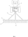
- FIG. 1 is a simplified top view illustrating a tractor 102 drawing a tillage implement 104, which includes a frame 106 supporting multiple tilling tools 108.
- a computer 110 which may include a processor 112, memory, and graphical user interface (“GUI") 118 ( e.g., a touch-screen interface), is typically located in the cab of the tractor 102.
- GUI graphical user interface
- a global positioning system (“GPS") receiver 114 may be mounted to the tractor 102 and connected to communicate with the processor 112.
- the processor 112 may be configured to communicate with the tilling tools 108.
- the processor 112 may communicate by wired or wireless communication.
- the processor 112 may be configured to adjust operating parameters of the tillage implement 104, store and retrieve information in a data storage device 116, and/or display information on the graphical user interface 118 (depicted as a touch-screen, though other types of interface may also be used).
- the processor 112 may typically adjust the operating parameters of the tillage implement 104 based on known variations of the properties of the field or based on information collected while working the field.
- the data storage device 116 may store one or more maps containing information about the field, and the processor 112 may adjust the tillage implement 104 based on the position in the field and information from the map(s).
- the maps may include, for example, topographic or soil-quality maps.
- FIG. 2 is a simplified representation of a map 200 of a field.
- the map 200 may include different areas 202-208 separated by boundaries 210-216.
- the areas 202-208 may have different soil characteristics, and the boundaries 210-216 may correspond to changes in the soil characteristics of a preselected magnitude.
- the map 200 represents the amount of residue over the soil (i.e., plant material that is not mixed into the soil)
- the boundaries 210-216 may divide values of residue into different bins, categories, or ranges ( e.g. , low, medium, and high; specific numerical values; or any other selected classifications).
- the areas 202 may have low residue
- the area 204 may have medium residue
- the areas 206 and 208 may each have high residue.
- the areas 202-208 may have different soil compositions, such as the amount of organic material, the amount of sand, the amount of clay, etc.
- the map 200 may include any number of areas 202-208 with any selected properties.
- the map 200 may include, in addition to or instead of soil characteristics, topographical information.
- the boundaries 210 and 212 may divide a lower area 202 from a higher area 204, whereas the boundaries 214 and 216 may separate certain areas 206 and 208 of soil having a high tendency to erode. Thus, it may be beneficial to till the area 202 differently than the areas 204-208.
- the computer 110 may correlate information about the field from the map 200 with a location of the tillage implement 104 as determined by the GPS receiver 114.
- the computer 110 may determine target values of operating parameters for the tillage implement 104 based on the properties of the soil at that particular location. If any operating parameter has a target value different from the current value of that operating parameter, the computer 110 may adjust the tillage implement 104 accordingly. This change typically occurs when the tillage implement 104 crosses the boundaries 210-216.
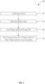
- FIG. 3 is a simplified flow chart illustrating a method 300 in which the tractor 102 and the tillage implement 104 ( FIG. 1 ) may be used to work a field.
- the method 300 includes providing a map (e.g ., map 200 in FIG. 2 ) of a field.
- the map may be a topographic map, a soil-quality map, a residue map, etc.
- the map may be provided to the computer 110 ( FIG. 1 ) by any method known in the art, such as by transmission via wired or wireless connections, and may be stored in the data storage device 116.
- the method 300 includes defining boundaries in the map.
- the boundaries may be defined to separate various areas of the map based on erosion propensity, elevation, or other soil characteristic properties.
- the boundaries may define different areas in which the tillage implement 104 will have different operating parameters.
- the method 300 includes propelling the tillage implement 104 through the field.
- the tillage implement 104 is typically pulled behind the tractor 102.
- the computer 110 adjusts an operating parameter of the tillage implement 104 (or instructs an actuator or other device to adjust an operating parameter) when the tillage implement 104 crosses a boundary.
- the computer 110 may adjust a depth of the tillage implement 104 with respect to the surface of the field, an aggressiveness of the tillage implement 104, a rolling basket pressure of the tillage implement 104 ( e.g., as described in U.S.
- Patent 9,635,797 "Actuator Adjusted Rolling Baskets," issued May 2, 2017 ) or a gang angle of the tillage implement 104 ( e.g., as described in International Patent Publication WO 2018/020307 A1, "Tillage Implement Having a Mechanism for Adjusting Disc Blade Angle,” published February 1, 2018 , and U.S. Patent Publication 2013/0048323, “Tillage Implement with Adjustable Gang Angle,” published September 17, 2013 ).
- Still other embodiments involve a computer-readable storage medium (e.g. , a non-transitory computer-readable storage medium) having processor-executable instructions configured to implement one or more of the techniques presented herein.
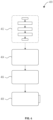
- An example computer-readable medium that may be devised is illustrated in FIG. 4 , wherein an implementation 400 includes a computer-readable storage medium 402 (e.g., a flash drive, CD-R, DVD-R, application-specific integrated circuit (ASIC), field-programmable gate array (FPGA), a platter of a hard disk drive, etc .), on which is computer-readable data 404.
- This computer-readable data 404 in turn includes a set of processor-executable instructions 406 configured to operate according to one or more of the principles set forth herein.
- the processor-executable instructions 406 may be configured to cause the computer 110 ( FIG. 1 ) to perform operations 408 when executed via a processing unit, such as at least some of the example method 300 depicted in FIG. 3 .
- the processor-executable instructions 406 may be configured to implement a system, such as at least some of the example tractor 102 and tillage implement 104 ( FIG. 1 ).
- Many such computer-readable media may be devised by those of ordinary skill in the art that are configured to operate in accordance with one or more of the techniques presented herein.
- the apparatus and methods disclosed herein may benefit a farmer by tailoring tilling operations based on different field conditions. Different areas within the field may be worked differently, and therefore the methods may avoid working highly erodible soil too aggressively. Furthermore, if adjusting the tillage implement is automated in a computer, the changes can be implemented more precisely than would be possible if the tractor operator were required to make manual adjustments in the field. Therefore, the end result of the methods may be better consistency of soil conditions after tilling and lower erosion rates. This may translate into higher crop yield and better return-on-investment for the farmer.
Landscapes
- Life Sciences & Earth Sciences (AREA)
- Engineering & Computer Science (AREA)
- Mechanical Engineering (AREA)
- Soil Sciences (AREA)
- Environmental Sciences (AREA)
- Zoology (AREA)
- Soil Working Implements (AREA)
- Agricultural Machines (AREA)
- Lifting Devices For Agricultural Implements (AREA)
- Management, Administration, Business Operations System, And Electronic Commerce (AREA)
- Cultivation Receptacles Or Flower-Pots, Or Pots For Seedlings (AREA)
Claims (15)
- Computerimplementiertes Verfahren zum Betreiben eines Bodenbearbeitungsgeräts (104), mit:einem Bereitstellen einer Karte (200) eines Felds;einem Definieren einer Mehrzahl von Grenzen (210, 212, 214, 216) in der Karte;einem Antreiben des Bodenbearbeitungsgeräts über das Feld; undeinem Einstellen mindestens eines Betriebsparameters des Bodenbearbeitungsgeräts, wenn das Bodenbearbeitungsgerät eine der mehreren Grenzen kreuzt;dadurch gekennzeichnet, dass das Definieren der Grenzen (210, 212, 214, 216) in der Karte (200) ein Definieren der Grenzen, um Bereiche basierend auf einer Erhebung oder Bodencharakteristik zu trennen, aufweist.
- Verfahren nach Anspruch 1, wobei das Bereitstellen der Karte (200) ein Bereitstellen einer topografischen Karte des Felds aufweist.
- Verfahren nach Anspruch 1, wobei das Bereitstellen der Karte (200) ein Bereitstellen einer Bodenkarte des Felds aufweist.
- Verfahren nach einem der Ansprüche 1 bis 3, wobei das Bereitstellen der Karte (200) ein Bereitstellen der Karte an einen Computer (110) aufweist, der von einem Traktor (102) getragen ist, welcher ausgebildet ist, um das Bodenbearbeitungsgerät (104) über das Feld anzutreiben.
- Verfahren nach Anspruch 4, wobei das Einstellen des mindestens einen Betriebsparameters des Bodenbearbeitungsgeräts (104) ein Senden eines elektronischen Signals von dem Computer (110) zu dem Bodenbearbeitungsgerät aufweist.
- Verfahren nach einem der Ansprüche 1 bis 3, wobei das Definieren der Grenzen (210, 212, 214, 216) in der Karte ein Definieren der Grenzen, um Bereiche (202, 204, 206, 208) basierend auf einer Erosionsneigung zu trennen, aufweist.
- Verfahren nach einem der Ansprüche 1 bis 3, wobei das Einstellen mindestens eines Betriebsparameters des Bodenbearbeitungsgeräts (104) ein Einstellen einer Tiefe des Bodenbearbeitungsgeräts aufweist.
- Verfahren nach einem der Ansprüche 1 bis 3, wobei das Einstellen mindestens eines Betriebsparameters des Bodenbearbeitungsgeräts (104) ein Einstellen einer Aggressivität des Bodenbearbeitungsgeräts aufweist.
- Verfahren nach einem der Ansprüche 1 bis 3, wobei das Einstellen mindestens eines Betriebsparameters des Bodenbearbeitungsgeräts (104) ein Einstellen eines Rollkorbdrucks des Bodenbearbeitungsgeräts aufweist.
- Verfahren nach einem der Ansprüche 1 bis 3, wobei das Einstellen mindestens eines Betriebsparameters des Bodenbearbeitungsgeräts (104) ein Einstellen eines Gangwinkels oder Bodenbearbeitungswerkzeugsatz-Winkels des Bodenbearbeitungsgeräts aufweist.
- Nichtflüchtiges computerlesbares Speichermedium (402), wobei das computerlesbare Speichermedium Instruktionen umfasst, die, wenn sie durch einen einem landwirtschaftlichen Traktor (102) zugeordneten Computer (110) ausgeführt werden, veranlassen, dass der landwirtschaftliche Traktor:ein Bodenbearbeitungsgerät (104) über ein Feld antreibt; undmindestens einen Betriebsparameter des Bodenbearbeitungsgeräts einstellt, wenn das Bodenbearbeitungsgerät eine Grenze (210, 212, 214, 216) kreuzt, die in einer Karte (200) definiert ist;dadurch gekennzeichnet, dass die Grenze zu einer Bodencharakteristik oder einer Erhebung korrespondiert.
- Nichtflüchtiges computerlesbares Speichermedium (402) nach Anspruch 11, weiterhin mit auf Kategorien der Bodencharakteristik oder Erhebung basierenden Grenzen (210, 212, 214, 216).
- Nichtflüchtiges computerlesbares Speichermedium (402) nach Anspruch 12, wobei zumindest einige der Grenzen (210, 212, 214, 216) auf einer Erosionsneigung basieren.
- Nichtflüchtiges computerlesbares Speichermedium (402) nach Anspruch 12, wobei zumindest einige der Grenzen (210, 212, 214, 216) auf einer Erhebung basieren.
- Nichtflüchtiges computerlesbares Speichermedium (402) nach einem der Ansprüche 11 bis 14, wobei die Instruktionen veranlassen, dass der Computer (110) mindestens einen Betriebsparameter einstellt, der eine Tiefe des Bodenbearbeitungsgeräts (104) und/oder eine Aggressivität des Bodenbearbeitungsgeräts und/oder ein Rollkorbdruck des Bodenbearbeitungsgeräts und/oder ein Gangwinkel oder Bodenbearbeitungswerkzeugsatz-Winkel des Bodenbearbeitungsgeräts ist.
Applications Claiming Priority (2)
| Application Number | Priority Date | Filing Date | Title |
|---|---|---|---|
| US201962859407P | 2019-06-10 | 2019-06-10 | |
| PCT/IB2020/052419 WO2020250043A1 (en) | 2019-06-10 | 2020-03-17 | Methods of operating tillage implements |
Publications (2)
| Publication Number | Publication Date |
|---|---|
| EP3979780A1 EP3979780A1 (de) | 2022-04-13 |
| EP3979780B1 true EP3979780B1 (de) | 2025-05-14 |
Family
ID=70110298
Family Applications (1)
| Application Number | Title | Priority Date | Filing Date |
|---|---|---|---|
| EP20716212.4A Active EP3979780B1 (de) | 2019-06-10 | 2020-03-17 | Verfahren zum betrieb von bodenbearbeitungsgeräten |
Country Status (5)
| Country | Link |
|---|---|
| US (1) | US20220183215A1 (de) |
| EP (1) | EP3979780B1 (de) |
| BR (1) | BR112021019462A2 (de) |
| PL (1) | PL3979780T3 (de) |
| WO (1) | WO2020250043A1 (de) |
Family Cites Families (14)
| Publication number | Priority date | Publication date | Assignee | Title |
|---|---|---|---|---|
| US6236907B1 (en) | 1995-05-30 | 2001-05-22 | Ag-Chem Equipment Co., Inc. | System and method for creating agricultural decision and application maps for automated agricultural machines |
| US6041582A (en) * | 1998-02-20 | 2000-03-28 | Case Corporation | System for recording soil conditions |
| WO2001097097A1 (en) | 2000-06-05 | 2001-12-20 | Ag-Chem Equipment Company, Inc. | System and method for creating field attribute maps for site-specific farming |
| US6834550B2 (en) | 2001-09-10 | 2004-12-28 | The Regents Of The University Of California | Soil profile force measurement using an instrumented tine |
| DE10250694B3 (de) * | 2002-10-31 | 2004-02-12 | CNH Österreich GmbH | Verfahren zur Steuerung eines landwirtschaftlichen Nutzfahrzeuges |
| US8522889B2 (en) * | 2010-08-30 | 2013-09-03 | Cnh America Llc | Agricultural implement with combined down force and depth control |
| US8534374B2 (en) | 2011-08-26 | 2013-09-17 | Great Plains Manufacturing, Inc. | Tillage implement with adjustable gang angle |
| US9635797B2 (en) | 2013-08-21 | 2017-05-02 | Cnh Industrial America Llc | Actuator adjusted rolling baskets |
| DK178793B1 (en) * | 2015-07-08 | 2017-02-20 | Agro Intelligence Aps | A plough system and a method for ploughing |
| WO2018020307A1 (en) | 2016-07-25 | 2018-02-01 | Agco Corporation | Tillage implement having a mechanism for adjusting disc blade angle |
| BR112019007797A2 (pt) | 2016-10-24 | 2019-07-09 | Agco International Gmbh | sistema de mapeamento e orientação terrestre |
| US10178823B2 (en) * | 2016-12-12 | 2019-01-15 | Cnh Industrial Canada, Ltd. | Agricultural implement with automatic shank depth control |
| CA3047779A1 (en) * | 2016-12-19 | 2018-06-28 | The Climate Corporation | Systems, methods and apparatus for soil and seed monitoring |
| US11895941B2 (en) * | 2019-09-23 | 2024-02-13 | Cnh Industrial America Llc | Tillage system with variable fertilizer application |
-
2020
- 2020-03-17 EP EP20716212.4A patent/EP3979780B1/de active Active
- 2020-03-17 BR BR112021019462A patent/BR112021019462A2/pt unknown
- 2020-03-17 PL PL20716212.4T patent/PL3979780T3/pl unknown
- 2020-03-17 WO PCT/IB2020/052419 patent/WO2020250043A1/en not_active Ceased
- 2020-03-17 US US17/594,350 patent/US20220183215A1/en not_active Abandoned
Also Published As
| Publication number | Publication date |
|---|---|
| EP3979780A1 (de) | 2022-04-13 |
| US20220183215A1 (en) | 2022-06-16 |
| BR112021019462A2 (pt) | 2021-12-21 |
| PL3979780T3 (pl) | 2025-09-08 |
| WO2020250043A1 (en) | 2020-12-17 |
Similar Documents
| Publication | Publication Date | Title |
|---|---|---|
| US12120971B2 (en) | Apparatus, system and method for monitoring soil criteria during tillage operations and control of tillage tools | |
| EP3892075B1 (de) | Systeme mit landwirtschaftlichen arbeitsgeräten, die mit hebevorrichtungen verbunden sind, sowie zugehörige steuerungssysteme und verfahren | |
| US20240188472A1 (en) | Agricultural implements having row unit position sensors and at least one adjustable wheel, and related control systems and methods | |
| EP3729931B1 (de) | Landwirtschaftliches system | |
| US20230354735A1 (en) | Agricultural implements having sensors to detect plugging of row units, and related control systems and methods | |
| EP3958663B1 (de) | Verfahren zum betrieb eines bodenbearbeitungsgerätes | |
| US12364186B2 (en) | Agricultural implements having row unit position sensors and a rotatable implement frame, and related control systems and methods | |
| US20220091089A1 (en) | Apparatus and methods for measuring soil conditions | |
| EP3979780B1 (de) | Verfahren zum betrieb von bodenbearbeitungsgeräten | |
| US20220386519A1 (en) | Automated tillage disk gang angle adjustment | |
| EP3982709B1 (de) | Verfahren zum betrieb von bodenbearbeitungsgeräten und bearbeiten von feldern | |
| US20230270039A1 (en) | Agricultural implements having row unit position sensors and actuators configured to rotate toolbars, and related control systems and methods | |
| Amonov et al. | Machine innovation for inter row cotton cultivation in Uzbekistan | |
| US20210045284A1 (en) | Tillage implements, systems, and methods for working a field | |
| WO2022038427A1 (en) | Implement having a link adjustable by means of a pneumatic actuator, and related method | |
| RU2807735C2 (ru) | Способ обработки почвы, способ управления оборудованием для обработки почвы и энергонезависимый читаемый компьютером носитель для хранения информации (варианты) | |
| RU2811462C2 (ru) | Способ регулирования рабочих параметров почвообрабатывающего орудия (варианты) и считываемый компьютером носитель для долговременного хранения информации для осуществления способа регулирования рабочих параметров почвообрабатывающего орудия (варианты) |
Legal Events
| Date | Code | Title | Description |
|---|---|---|---|
| STAA | Information on the status of an ep patent application or granted ep patent |
Free format text: STATUS: UNKNOWN |
|
| STAA | Information on the status of an ep patent application or granted ep patent |
Free format text: STATUS: THE INTERNATIONAL PUBLICATION HAS BEEN MADE |
|
| PUAI | Public reference made under article 153(3) epc to a published international application that has entered the european phase |
Free format text: ORIGINAL CODE: 0009012 |
|
| STAA | Information on the status of an ep patent application or granted ep patent |
Free format text: STATUS: REQUEST FOR EXAMINATION WAS MADE |
|
| 17P | Request for examination filed |
Effective date: 20220110 |
|
| AK | Designated contracting states |
Kind code of ref document: A1 Designated state(s): AL AT BE BG CH CY CZ DE DK EE ES FI FR GB GR HR HU IE IS IT LI LT LU LV MC MK MT NL NO PL PT RO RS SE SI SK SM TR |
|
| DAV | Request for validation of the european patent (deleted) | ||
| DAX | Request for extension of the european patent (deleted) | ||
| P01 | Opt-out of the competence of the unified patent court (upc) registered |
Effective date: 20230518 |
|
| GRAP | Despatch of communication of intention to grant a patent |
Free format text: ORIGINAL CODE: EPIDOSNIGR1 |
|
| STAA | Information on the status of an ep patent application or granted ep patent |
Free format text: STATUS: GRANT OF PATENT IS INTENDED |
|
| INTG | Intention to grant announced |
Effective date: 20241206 |
|
| GRAS | Grant fee paid |
Free format text: ORIGINAL CODE: EPIDOSNIGR3 |
|
| GRAA | (expected) grant |
Free format text: ORIGINAL CODE: 0009210 |
|
| STAA | Information on the status of an ep patent application or granted ep patent |
Free format text: STATUS: THE PATENT HAS BEEN GRANTED |
|
| AK | Designated contracting states |
Kind code of ref document: B1 Designated state(s): AL AT BE BG CH CY CZ DE DK EE ES FI FR GB GR HR HU IE IS IT LI LT LU LV MC MK MT NL NO PL PT RO RS SE SI SK SM TR |
|
| REG | Reference to a national code |
Ref country code: GB Ref legal event code: FG4D |
|
| REG | Reference to a national code |
Ref country code: CH Ref legal event code: EP |
|
| REG | Reference to a national code |
Ref country code: IE Ref legal event code: FG4D |
|
| REG | Reference to a national code |
Ref country code: DE Ref legal event code: R096 Ref document number: 602020051231 Country of ref document: DE |
|
| REG | Reference to a national code |
Ref country code: NL Ref legal event code: MP Effective date: 20250514 |
|
| PG25 | Lapsed in a contracting state [announced via postgrant information from national office to epo] |
Ref country code: ES Free format text: LAPSE BECAUSE OF FAILURE TO SUBMIT A TRANSLATION OF THE DESCRIPTION OR TO PAY THE FEE WITHIN THE PRESCRIBED TIME-LIMIT Effective date: 20250514 Ref country code: FI Free format text: LAPSE BECAUSE OF FAILURE TO SUBMIT A TRANSLATION OF THE DESCRIPTION OR TO PAY THE FEE WITHIN THE PRESCRIBED TIME-LIMIT Effective date: 20250514 Ref country code: PT Free format text: LAPSE BECAUSE OF FAILURE TO SUBMIT A TRANSLATION OF THE DESCRIPTION OR TO PAY THE FEE WITHIN THE PRESCRIBED TIME-LIMIT Effective date: 20250915 |
|
| REG | Reference to a national code |
Ref country code: LT Ref legal event code: MG9D |
|
| PG25 | Lapsed in a contracting state [announced via postgrant information from national office to epo] |
Ref country code: NO Free format text: LAPSE BECAUSE OF FAILURE TO SUBMIT A TRANSLATION OF THE DESCRIPTION OR TO PAY THE FEE WITHIN THE PRESCRIBED TIME-LIMIT Effective date: 20250814 Ref country code: GR Free format text: LAPSE BECAUSE OF FAILURE TO SUBMIT A TRANSLATION OF THE DESCRIPTION OR TO PAY THE FEE WITHIN THE PRESCRIBED TIME-LIMIT Effective date: 20250815 |
|
| PG25 | Lapsed in a contracting state [announced via postgrant information from national office to epo] |
Ref country code: NL Free format text: LAPSE BECAUSE OF FAILURE TO SUBMIT A TRANSLATION OF THE DESCRIPTION OR TO PAY THE FEE WITHIN THE PRESCRIBED TIME-LIMIT Effective date: 20250514 |
|
| REG | Reference to a national code |
Ref country code: AT Ref legal event code: MK05 Ref document number: 1793959 Country of ref document: AT Kind code of ref document: T Effective date: 20250514 |
|
| PG25 | Lapsed in a contracting state [announced via postgrant information from national office to epo] |
Ref country code: BG Free format text: LAPSE BECAUSE OF FAILURE TO SUBMIT A TRANSLATION OF THE DESCRIPTION OR TO PAY THE FEE WITHIN THE PRESCRIBED TIME-LIMIT Effective date: 20250514 |
|
| PG25 | Lapsed in a contracting state [announced via postgrant information from national office to epo] |
Ref country code: HR Free format text: LAPSE BECAUSE OF FAILURE TO SUBMIT A TRANSLATION OF THE DESCRIPTION OR TO PAY THE FEE WITHIN THE PRESCRIBED TIME-LIMIT Effective date: 20250514 |
|
| PG25 | Lapsed in a contracting state [announced via postgrant information from national office to epo] |
Ref country code: AT Free format text: LAPSE BECAUSE OF FAILURE TO SUBMIT A TRANSLATION OF THE DESCRIPTION OR TO PAY THE FEE WITHIN THE PRESCRIBED TIME-LIMIT Effective date: 20250514 |
|
| PG25 | Lapsed in a contracting state [announced via postgrant information from national office to epo] |
Ref country code: RS Free format text: LAPSE BECAUSE OF FAILURE TO SUBMIT A TRANSLATION OF THE DESCRIPTION OR TO PAY THE FEE WITHIN THE PRESCRIBED TIME-LIMIT Effective date: 20250814 |
|
| PG25 | Lapsed in a contracting state [announced via postgrant information from national office to epo] |
Ref country code: IS Free format text: LAPSE BECAUSE OF FAILURE TO SUBMIT A TRANSLATION OF THE DESCRIPTION OR TO PAY THE FEE WITHIN THE PRESCRIBED TIME-LIMIT Effective date: 20250914 |
|
| PG25 | Lapsed in a contracting state [announced via postgrant information from national office to epo] |
Ref country code: LV Free format text: LAPSE BECAUSE OF FAILURE TO SUBMIT A TRANSLATION OF THE DESCRIPTION OR TO PAY THE FEE WITHIN THE PRESCRIBED TIME-LIMIT Effective date: 20250514 |
|
| PG25 | Lapsed in a contracting state [announced via postgrant information from national office to epo] |
Ref country code: SM Free format text: LAPSE BECAUSE OF FAILURE TO SUBMIT A TRANSLATION OF THE DESCRIPTION OR TO PAY THE FEE WITHIN THE PRESCRIBED TIME-LIMIT Effective date: 20250514 Ref country code: DK Free format text: LAPSE BECAUSE OF FAILURE TO SUBMIT A TRANSLATION OF THE DESCRIPTION OR TO PAY THE FEE WITHIN THE PRESCRIBED TIME-LIMIT Effective date: 20250514 |
|
| PG25 | Lapsed in a contracting state [announced via postgrant information from national office to epo] |
Ref country code: CZ Free format text: LAPSE BECAUSE OF FAILURE TO SUBMIT A TRANSLATION OF THE DESCRIPTION OR TO PAY THE FEE WITHIN THE PRESCRIBED TIME-LIMIT Effective date: 20250514 |
|
| PG25 | Lapsed in a contracting state [announced via postgrant information from national office to epo] |
Ref country code: EE Free format text: LAPSE BECAUSE OF FAILURE TO SUBMIT A TRANSLATION OF THE DESCRIPTION OR TO PAY THE FEE WITHIN THE PRESCRIBED TIME-LIMIT Effective date: 20250514 |
|
| PG25 | Lapsed in a contracting state [announced via postgrant information from national office to epo] |
Ref country code: SK Free format text: LAPSE BECAUSE OF FAILURE TO SUBMIT A TRANSLATION OF THE DESCRIPTION OR TO PAY THE FEE WITHIN THE PRESCRIBED TIME-LIMIT Effective date: 20250514 Ref country code: RO Free format text: LAPSE BECAUSE OF FAILURE TO SUBMIT A TRANSLATION OF THE DESCRIPTION OR TO PAY THE FEE WITHIN THE PRESCRIBED TIME-LIMIT Effective date: 20250514 |
|
| PG25 | Lapsed in a contracting state [announced via postgrant information from national office to epo] |
Ref country code: IT Free format text: LAPSE BECAUSE OF FAILURE TO SUBMIT A TRANSLATION OF THE DESCRIPTION OR TO PAY THE FEE WITHIN THE PRESCRIBED TIME-LIMIT Effective date: 20250514 |