EP3979665B1 - Hörgeräte und verfahren zur implementierung einer adaptiv angepassten grenzfrequenz - Google Patents
Hörgeräte und verfahren zur implementierung einer adaptiv angepassten grenzfrequenz Download PDFInfo
- Publication number
- EP3979665B1 EP3979665B1 EP21198255.8A EP21198255A EP3979665B1 EP 3979665 B1 EP3979665 B1 EP 3979665B1 EP 21198255 A EP21198255 A EP 21198255A EP 3979665 B1 EP3979665 B1 EP 3979665B1
- Authority
- EP
- European Patent Office
- Prior art keywords
- audio signal
- frequency
- input
- cut
- input audio
- Prior art date
- Legal status (The legal status is an assumption and is not a legal conclusion. Google has not performed a legal analysis and makes no representation as to the accuracy of the status listed.)
- Active
Links
Images





Classifications
-
- H—ELECTRICITY
- H04—ELECTRIC COMMUNICATION TECHNIQUE
- H04R—LOUDSPEAKERS, MICROPHONES, GRAMOPHONE PICK-UPS OR LIKE ACOUSTIC ELECTROMECHANICAL TRANSDUCERS; ELECTRIC HEARING AIDS; PUBLIC ADDRESS SYSTEMS
- H04R25/00—Electric hearing aids
- H04R25/35—Electric hearing aids using translation techniques
- H04R25/353—Frequency, e.g. frequency shift or compression
-
- H—ELECTRICITY
- H04—ELECTRIC COMMUNICATION TECHNIQUE
- H04R—LOUDSPEAKERS, MICROPHONES, GRAMOPHONE PICK-UPS OR LIKE ACOUSTIC ELECTROMECHANICAL TRANSDUCERS; ELECTRIC HEARING AIDS; PUBLIC ADDRESS SYSTEMS
- H04R1/00—Details of transducers, loudspeakers or microphones
- H04R1/20—Arrangements for obtaining desired frequency or directional characteristics
- H04R1/22—Arrangements for obtaining desired frequency or directional characteristics for obtaining desired frequency characteristic only
- H04R1/227—Arrangements for obtaining desired frequency or directional characteristics for obtaining desired frequency characteristic only using transducers reproducing the same frequency band
-
- H—ELECTRICITY
- H04—ELECTRIC COMMUNICATION TECHNIQUE
- H04R—LOUDSPEAKERS, MICROPHONES, GRAMOPHONE PICK-UPS OR LIKE ACOUSTIC ELECTROMECHANICAL TRANSDUCERS; ELECTRIC HEARING AIDS; PUBLIC ADDRESS SYSTEMS
- H04R2225/00—Details of deaf aids covered by H04R25/00, not provided for in any of its subgroups
- H04R2225/43—Signal processing in hearing aids to enhance the speech intelligibility
-
- H—ELECTRICITY
- H04—ELECTRIC COMMUNICATION TECHNIQUE
- H04R—LOUDSPEAKERS, MICROPHONES, GRAMOPHONE PICK-UPS OR LIKE ACOUSTIC ELECTROMECHANICAL TRANSDUCERS; ELECTRIC HEARING AIDS; PUBLIC ADDRESS SYSTEMS
- H04R25/00—Electric hearing aids
- H04R25/50—Customised settings for obtaining desired overall acoustical characteristics
- H04R25/505—Customised settings for obtaining desired overall acoustical characteristics using digital signal processing
Definitions
- Hearing devices e.g., hearing aids
- Such hearing devices are configured to process a received input sound signal (e.g., ambient sound) and provide the processed input sound signal to the user (e.g., by way of a receiver (e.g., a speaker) placed in the user's ear canal or at any other suitable location).
- a received input sound signal e.g., ambient sound
- a receiver e.g., a speaker
- US 2016/0324448 A1 describes a method for fitting a hearing device to the needs of a user which includes setting a cut-off frequency for a frequency lowering algorithm within a cut-off frequency range.
- Yang et al. (“Effects of nonlinear frequency compression on the acoustic properties and recognition of speech sounds in Mandarin Chinese", The Journal of the Acoustical Society of America, AIP, vol. 143, no. 3 ) describes an adaptive frequency-lowering algorithm which switches between a lower and a higher predefined cut-off frequency.
- frequency lowering algorithms may unnecessarily reserve a portion of available output bandwidth to receive high-frequency compressed content, which may result in significantly compressing original harmonics in an input audio signal and undesired artifacts in an output audio signal.
- the invention provides a hearing device according to claim 1 and a method according to claim 8. Further embodiments are defined in the dependent claims.
- the invention concerns a hearing device which comprises a memory storing instructions and a processor communicatively coupled to the memory.
- a hearing device may be implemented by an in-the-ear ("ITE") component configured to at least partially be inserted within an ear canal of a user.
- ITE in-the-ear
- a hearing device may include a combination of an ITE component, a BTE component, and/or any other suitable component.
- the adaptively adjusting of the cut-off frequency as the continuous function of the input audio signal includes adaptively adjusting the cut-off frequency as a continuous function of an instantaneous input bandwidth of the input audio signal.
- no frequency compression is applied to the input audio signal during the mapping, when the instantaneous input bandwidth of the input audio signal is less than the predefined minimum cut-off frequency value.
- the processor is further configured to execute the instructions to apply, when the instantaneous input bandwidth of the input audio signal is between the predefined minimum cut-off frequency value and the predefined maximum cut-off frequency value, a fixed frequency compression ratio to modify the range of frequencies of the input audio signal, wherein the generating of the output audio signal includes mapping the range of input frequencies, as modified based on the fixed frequency compression ratio, to the range of output frequencies.
- the processor is further configured to execute the instructions to apply, when the instantaneous input bandwidth of the input audio signal is between the predefined minimum cut-off frequency value and the predefined maximum cut-off frequency value, an input bandwidth-dependent frequency compression ratio to modify the range of frequencies of the input audio signal, wherein the generating of the output audio signal includes mapping the range of input frequencies, as modified based on the input bandwidth-dependent frequency compression ratio, to the range of output frequencies.
- the adaptively adjusted cut-off frequency decreases as the instantaneous input bandwidth increases, when the instantaneous input bandwidth of the input audio signal is between the predefined minimum cut-off frequency value and the predefined maximum cut-off frequency value.
- the cut-off frequency is set to the predefined minimum cut-off frequency value, when the instantaneous input bandwidth is above the predefined maximum cut-off frequency value.
- the instantaneous input bandwidth of the input audio signal is defined as a frequency associated with a first bin index of a particular input frame of the input audio signal that reaches a predefined percentage of a total energy of the particular input frame of the input audio signal.
- the predefined percentage is equal to or greater than ninety percent of the total energy of the particular input frame of the input audio signal.
- the adaptively adjusting of the cut-off frequency as the continuous function of the input audio signal includes adaptively adjusting the cut-off frequency as a continuous function of an instantaneous input level of the input audio signal.
- the processor is further configured to execute the instructions to apply a pre-compensation filter to the input audio signal to mitigate low frequency masking of the output audio signal.
- the processor is further configured to execute the instructions to provide the output audio signal to a receiver configured to represent the output audio signal to a user of the hearing device.
- the invention also concerns a method comprising: receiving, by a processor of a hearing device, an input audio signal having a range of input frequencies; adaptively adjusting, by the processor of the hearing device, a cut-off frequency for the input audio signal such that a value of the cut-off frequency varies between a predefined minimum cut-off frequency value and a predefined maximum cut-off frequency value as a continuous function of the input audio signal; and generating, by the processor of the hearing device, an output audio signal by mapping the range of input frequencies to a range of output frequencies determined based on the adaptively adjusted cut-off frequency.
- the adaptively adjusting of the cut-off frequency as the continuous function of the input audio signal includes adaptively adjusting the cut-off frequency as a continuous function of an instantaneous input bandwidth of the input audio signal.
- the method further comprises applying, by the processor of the hearing device when the instantaneous input bandwidth of the input audio signal is between the predefined minimum cut-off frequency value and the predefined maximum cut-off frequency value, a fixed frequency compression ratio to modify the range of frequencies of the input audio signal, wherein the generating of the output audio signal includes mapping the range of input frequencies, as modified based on the fixed frequency compression ratio, to the range of output frequencies.
- the method further comprises applying, by the processor of the hearing device when the instantaneous input bandwidth of the input audio signal is between the predefined minimum cut-off frequency value and the predefined maximum cut-off frequency value, an input bandwidth-dependent frequency compression ratio to modify the range of frequencies of the input audio signal, wherein the generating of the output audio signal includes mapping the range of input frequencies, as modified based on the input bandwidth-dependent frequency compression ratio, to the range of output frequencies.
- the instantaneous input bandwidth of the input audio signal is defined as a frequency associated with a first bin index of a particular input frame of the input audio signal that reaches a predefined percentage of a total energy of the particular input frame of the input audio signal.
- the predefined percentage is equal to or greater than ninety percent of the total energy of the particular input frame of the input audio signal.
- the method further comprises applying, by the processor of the hearing device, a pre-compensation filter to the input audio signal to mitigate low frequency masking of the output audio signal.
- the invention also concerns a non-transitory computer readable storage medium storing instructions that, when executed, direct a processor to perform the method of the invention as described herein.
- FIG. 1 illustrates an exemplary hearing device 100 that may be implemented according to principles described herein.
- hearing device 100 may include, without limitation, a memory 102 and a processor 104 selectively and communicatively coupled to one another.
- Memory 102 and processor 104 may each include or be implemented by hardware and/or software components (e.g., processors, memories, communication interfaces, instructions stored in memory for execution by the processors, etc.).
- Memory 102 may maintain (e.g., store) executable data used by processor 104 to perform any of the operations associated with implementing an adaptively adjusted cut-off frequency.
- memory 102 may store instructions 106 that may be executed by processor 104 to perform any of the operations associated with hearing device 100 described herein.
- Instructions 106 may be implemented by any suitable application, software, code, and/or other executable data instance.
- Memory 102 may also maintain any data received, generated, managed, used, and/or transmitted by processor 104.
- memory 102 may maintain hearing loss data 108 that may be representative of any information associated with a hearing loss profile of a user of hearing device 100, predefined maximum cut-off frequency values, predefined minimum cut-off frequency values, and/or any other suitable information.
- memory 102 may maintain any data suitable to facilitate communications (e.g., wired and/or wireless communications) between hearing device 100 and one or more additional computing devices, such as those described herein.
- Memory 102 may maintain additional or alternative data in other implementations.
- Processor 104 is configured to perform any suitable processing operation that may be associated with hearing device 100 such as by representing audio content to a user of hearing device 100.
- processing operations may include monitoring ambient sound and/or representing sound to a user via an in-ear receiver.
- processing operations may include directing a cochlear implant to generate and apply electrical stimulation representative of one or more audio signals (e.g., one or more audio signals detected by a microphone, input by way of an auxiliary audio input port, etc.) to one or more stimulation sites associated with an auditory pathway (e.g., the auditory nerve) of a user.
- an auditory pathway e.g., the auditory nerve
- Processor 104 may be configured to perform (e.g., execute instructions 106 stored in memory 102 to perform) various processing operations associated with implementing an adaptively adjusted cut-off frequency.
- processing operations may include receiving an input audio signal having a range of input frequencies, adaptively adjusting a cut-off frequency for the input audio signal such that a value of the cut-off frequency varies between a predefined minimum cut-off frequency value and a predefined maximum cut-off frequency value as a continuous function of the input audio signal, and generating an output audio signal by mapping the range of input frequencies to a range of output frequencies determined based on the adaptively adjusted cut-off frequency.
- FIG. 2 shows an exemplary flowchart 200 that depicts operations that may be performed by hearing device 100 (e.g., processor 104) according to principles described herein.
- hearing device 100 may receive an input audio signal at operation 202.
- Hearing device 100 may receive the input audio signal in any suitable manner.
- hearing device 100 may receive the input audio signal as ambient sound captured by a microphone included as part of or otherwise communicatively connected to hearing device 100.
- hearing device 100 may receive the input audio signal from an external computing device (e.g., a smartphone, a tablet computer, a desktop computer, etc.) by way of any suitable wired or wireless communication protocol (e.g., Bluetooth, Wi-Fi, etc.).
- an external computing device e.g., a smartphone, a tablet computer, a desktop computer, etc.
- any suitable wired or wireless communication protocol e.g., Bluetooth, Wi-Fi, etc.
- hearing device 100 may perform an input audio signal computation to process the input audio signal to facilitate adaptively adjusting a cut-off frequency of the input audio signal.
- Hearing device may perform any suitable processing operation or combination of processing operations as may serve a particular implementation.
- hearing device 100 may transform the input audio signal from a time domain to a frequency domain by applying a transformation function to obtain an input spectrum having a range of input frequencies.
- hearing device 100 may perform a computation to adaptively adjust a cut-off frequency for the input audio signal. This may be accomplished in any suitable manner. For example, hearing device 100 may adaptively adjust a cut-off frequency for the input audio signal such that a value of the cut-off frequency varies between a predefined minimum cut-off frequency value and a predefined maximum cut-off frequency value as a continuous function of the input audio signal.
- the predefined minimum cut-off frequency value may correspond to any suitable fixed value that is sufficient to preserve low frequency vowel structures of the input audio signal.
- the predefined maximum cut-off frequency value may correspond to any suitable fixed maximum output frequency value that represents an upper limit of the remaining hearing bandwidth of a particular user of hearing device 100.
- No output audio content may be provided above the predefined maximum cut-off frequency value because the particular user of hearing device 100 may have no ability to perceive the output audio content and/or the gain required to provide output audio content may be excessively high.
- the particular values for the predefined minimum cut-off frequency value and the predefined maximum cut-off frequency value may be user specific and may be determined in any suitable manner (e.g., based on hearing loss data 108 stored by memory 102).
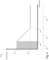
- FIG. 3 shows an exemplary graph 300 that depicts a range in which an adaptively adjusted cut-off frequency may vary.
- a frequency range of an input audio signal is represented on the x-axis and a frequency range of an output audio signal is represented on the y-axis.
- the input audio signal includes a range of frequencies from 0 Hz to an upper frequency value 302.
- the input audio signal shown in FIG. 3 includes predefined minimum cut-off frequency value 304 and a predefined maximum cut-off frequency value 306.
- Hearing device 100 is configured to adaptively adjust the cut-off frequency within a frequency range 308 such that the cut-off frequency may have a value corresponding to predefined minimum cut-off frequency value 304, predefined maximum cut-off frequency value 306, or any value therebetween depending on the input audio signal.
- the output audio signal along the y-axis in FIG. 3 has a frequency range from 0 Hz to a maximum output frequency 310. As shown in FIG. 3 , a minimum output frequency 312 is provided along the frequency range of the output audio signal. Minimum output frequency 312 may be associated with an output frequency at which frequency compression may occur.
- hearing device 100 may generate an output audio signal by mapping the range of input frequencies to a range of output frequencies determined based on the adaptively adjusted cut-off frequency.
- Hearing device 100 may map the range of input frequencies to the range of output frequencies in any suitable manner. For example, hearing device 100 may replace at least some of the frequency components in the range of output frequencies with at least some of the frequency components in the range of input frequencies. Additionally or alternatively, hearing device 100 may combine at least some of the frequency components in the range of output frequencies with at least some of the frequency components in the range of input frequencies.
- operation 210 may include mapping the range of input frequencies, as modified based on the fixed compression ratio, to the range of output frequencies.
- the mapping of the range of input frequencies to the range of output frequencies may include nonlinear frequency compression where lower frequencies may be unprocessed while higher frequencies may be compressed in greater amounts.
- the output audio signal generated at operation 210 may be represented to a user of hearing device 100 in any suitable manner.
- hearing device 100 may provide the output audio signal to a receiver (e.g., a speaker) placed in the user's ear canal or at any other suitable location.
- a receiver e.g., a speaker
- hearing device 100 may adaptively adjust the cut-off frequency as a continuous function of an instantaneous input bandwidth of the input audio signal.
- the instantaneous input bandwidth of the input audio signal may be defined in any suitable manner.
- the instantaneous input bandwidth of the input audio signal may be defined as a frequency associated with a first bin index of a particular input frame of the input audio signal that reaches a predefined percentage of a total energy of the particular input frame of the input audio signal.
- the predefined percentage may be equal to or greater than ninety percent of the total energy of the particular input frame.
- FIG. 4 shows an exemplary graph 400 that depicts how a value of an adaptively adjusted cut-off frequency may change within a plurality of different frequency ranges 402, 404, and 406 as a function of the instantaneous input bandwidth.
- frequency range 402 corresponds to a region where the instantaneous input bandwidth of the input audio signal is less than or equal to a predefined minimum cut-off frequency value 408. This may occur when most of the energy of the input audio signal is in low frequencies (e.g., by having vowel sounds).
- hearing device 100 may be configured to set the cut-off frequency to a predefined maximum cut-off frequency value 410. In so doing, in frequency range 402, no frequency compression is applied to the input audio signal during the mapping of the range of input frequencies to the range of output frequencies.
- Frequency range 404 corresponds to a region where the instantaneous input bandwidth is between predefined minimum cut-off frequency value 408 and a predefined maximum cut-off frequency value 410. As shown in FIG. 4 , while the instantaneous input bandwidth is within frequency range 404, hearing device 100 is configured to decrease the adaptively adjusted cut-off frequency as the instantaneous input bandwidth increases. In so doing, the adaptively adjusted cut-off frequency may vary within frequency range 404 depending on the instantaneous input bandwidth of the input audio signal.
- Frequency range 406 corresponds to a region where the instantaneous input bandwidth is greater than predefined maximum cut-off frequency value 410.
- hearing device 100 is configured to set the adaptively adjusted cut-off frequency to predefined minimum cut-off frequency value 408.
- FIGS. 5A-5C show exemplary graphs that depict the adaptively adjusted cut-off frequency while the instantaneous input bandwidth is within each of the frequency ranges 402, 404, and 406 shown in FIG. 4 .
- the instantaneous input bandwidth is within frequency range 402 shown in FIG. 4 .
- hearing device 100 sets an adaptively adjusted cut-off frequency 502 to a value that corresponds to a predefined maximum frequency value 504 and the input audio content between 0 Hz and adaptively adjusted cut-off frequency 502 is mapped to the output audio signal with no modification (e.g., fully linear). In so doing, it is possible to prevent artifacts from being introduced into the output audio signal and maximize sound quality.
- the instantaneous input bandwidth is within frequency range 404 shown in FIG. 4 .
- adaptively adjusted cut-off frequency 502 is between predefined maximum frequency value 504 and a predefined minimum frequency value 506.
- the input audio signal is broadband and adaptively adjusted cut-off frequency 502 linearly decreases with increasing bandwidth of the instantaneous input bandwidth. In so doing, a relatively larger area of the range of frequencies of the output audio signal may be devoted to receive high-frequency compressed content.
- the instantaneous input bandwidth is within frequency range 406 shown in FIG. 4 .
- a significant part of the energy of the input audio signal may be located in the high frequencies due to, for example, fricative consonants being present in the input audio signal.
- adaptively adjusted cut-off frequency 502 is set in FIG. 5C to predefined minimum frequency value 506. With such a configuration, a relatively larger amount of output frequency (e.g., between the minimum output frequency and the maximum output frequency) is devoted to receive high-frequency compressed content.
- hearing device 100 may implement an adaptive frequency compression ratio instead of a fixed frequency compression ratio.
- hearing device 100 may implement an input bandwidth-dependent frequency compression ratio to modify the range of frequencies of the input audio signal.
- the compression ratio may operate in a manner similar to that shown in FIG. 5A if the instantaneous input bandwidth is less than or equal to predefined minimum frequency value 408 shown in FIG. 4 . That is, in such an example, no frequency compression may be applied to the input audio signal while mapping the range of frequencies of the input audio signal to the range of output frequencies of the output audio signal.
- the adaptively adjusted cut-off frequency may be computed as shown in FIG. 4 and an adaptive frequency compression ratio may be implemented that decreases as the instantaneous input bandwidth increases. If, on the other hand, the instantaneous input bandwidth is greater than predefined maximum cut-off frequency value 410 shown in FIG. 4 , then the frequency compression ratio may be fixed and may be determined in any suitable manner.
- hearing device 100 may map the range of input frequencies of an input audio signal, as modified based on the adaptive frequency compression ratio, to the range of output frequencies of the output audio signal.
- an adaptive frequency compression ratio e.g., an input bandwidth-dependent frequency compression ratio
- hearing device 100 may adaptively adjust the cut-off frequency as a continuous function of an instantaneous input level of the input audio signal.
- Hearing device 100 may use the instantaneous input level of the input audio signal in any suitable manner to adaptively adjust the cut-off frequency.
- hearing device 100 may use the instantaneous input level in a manner similar to the instantaneous input bandwidth such as described herein.
- hearing device 100 may implement a pre-compensation filter to mitigate low-frequency masking of an output audio signal.
- the spread of masking by low frequencies to high frequencies becomes larger at relatively higher input levels. For example, high frequencies that would not be masked by a low-frequency sound at a level of 50 dB sound pressure level (SPL) may be masked by the same masker at 80 dB SPL.
- hearing device 100 may determine and apply a pre-compensation filter to an input audio signal.
- Such a pre-compensation filter may correspond to an adaptive pre-compensation filter that takes into account an overall SPL in an environment surrounding hearing device 100 as well as a balance between low-frequency and high-frequency energies of the input audio signal.
- Hearing device 100 may determine the pre-compensation filter in any suitable manner.
- a pre-compensation filter may take as input the SPL derived in bark bands E bark , which is a 20x1 vector.
- E BB may be set to E max . If E BB ⁇ E min (where E min is typically 50dB SPL), no pre-compensation filter is applied.
- ⁇ 1 may be associated with a frequency range of 172-347 Hz
- ⁇ 2 may be associated with a frequency range of 347-689 Hz
- ⁇ 3 may be associated with a frequency range of 689-1378 Hz.
- a 64x1 vector C containing frequency domain gains of the pre-compensation filter expressed in dB may be initialized with zeros.
- pre-compensation filter may be determined in any other suitable manner as may serve a particular implementation.
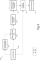
- FIG. 6 illustrates an exemplary flowchart 600 in which a pre-compensation filter may be applied to an input audio signal.
- hearing device 100 may receive an input audio signal at operation 602. This may be accomplished in any suitable manner such as described herein.
- hearing device 100 may perform a pre-compensation filter computation. This may be accomplished in any suitable manner such as described herein.
- hearing device 100 may perform one or more additional processing operations on the input audio signal. For example, hearing device 100 may perform a bin to bark conversion, a computation of the SPL in bark, and/or any other suitable processing operation.
- hearing device 100 may apply the computed pre-compensation filter to the input audio signal. This may be accomplished in any suitable manner.
- hearing device 100 may perform an input bandwidth computation on the input audio signal as adjusted by the pre-compensation filter. This may be accomplished in any suitable manner such as described herein.
- hearing device 100 may perform an adaptively adjusted cut-off frequency computation. This may be accomplished in any suitable manner such as described herein.
- hearing device 100 may perform a frequency compression operation. As described herein, whether hearing device 100 performs frequency compression may depend on the input audio signal. For example, if the instantaneous input bandwidth of the input audio signal is equal to or less than a predefined minimum frequency value, hearing device 100 may not perform operation 612 on the input audio signal.
- hearing device 100 may generate an output audio signal based on the audio signals and/or data received, generated, etc. at operations 602-612.
- FIG. 7 illustrates an exemplary method 700 for implementing an adaptively adjusted cut-off frequency. While FIG. 7 illustrates exemplary operations according to one embodiment, other embodiments may omit, add to, reorder, and/or modify any of the operations shown in FIG. 7 . One or more of the operations shown in FIG. 7 may be performed by a hearing device such as hearing device 100, any components included therein, and/or any implementation thereof.
- a processor may determine, while a hearing device (e.g., hearing device 100) is configured to receive an input audio signal having a range of input frequencies. Operation 702 may be performed in any of the ways described herein.
- the processor may adaptively adjust a cut-off frequency for the input audio signal such that a value of the cut-off frequency varies between a predefined minimum cut-off frequency value and a predefined maximum cut-off frequency value as a continuous function of the input audio signal. Operation 704 may be performed in any of the ways described herein.
- the processor may generate an output audio signal by mapping the range of input frequencies to a range of output frequencies determined based on the adaptively adjusted cut-off frequency. Operation 706 may be performed in any of the ways described herein.
- a non-transitory computer-readable medium storing computer-readable instructions may be provided in accordance with the principles described herein.
- the instructions when executed by a processor of a computing device, may direct the processor and/or computing device to perform one or more operations, including one or more of the operations described herein.
- Such instructions may be stored and/or transmitted using any of a variety of known computer-readable media.
- a non-transitory computer-readable medium as referred to herein may include any non-transitory storage medium that participates in providing data (e.g., instructions) that may be read and/or executed by a computing device (e.g., by a processor of a computing device).
- a non-transitory computer-readable medium may include, but is not limited to, any combination of non-volatile storage media and/or volatile storage media.
- Exemplary non-volatile storage media include, but are not limited to, read-only memory, flash memory, a solid-state drive, a magnetic storage device (e.g.
- RAM ferroelectric random-access memory
- optical disc e.g., a compact disc, a digital video disc, a Blu-ray disc, etc.
- RAM e.g., dynamic RAM
- FIG. 8 illustrates an exemplary computing device 800 that may be specifically configured to perform one or more of the processes described herein.
- computing device 800 may include a communication interface 802, a processor 804, a storage device 806, and an input/output (“I/O") module 808 communicatively connected one to another via a communication infrastructure 810.
- I/O input/output
- FIG. 8 the components illustrated in FIG. 8 are not intended to be limiting. Additional or alternative components may be used in other embodiments. Components of computing device 800 shown in FIG. 8 will now be described in additional detail.
- Communication interface 802 may be configured to communicate with one or more computing devices.
- Examples of communication interface 802 include, without limitation, a wired network interface (such as a network interface card), a wireless network interface (such as a wireless network interface card), a modem, an audio/video connection, and any other suitable interface.
- Processor 804 generally represents any type or form of processing unit capable of processing data and/or interpreting, executing, and/or directing execution of one or more of the instructions, processes, and/or operations described herein. Processor 804 may perform operations by executing computer-executable instructions 812 (e.g., an application, software, code, and/or other executable data instance) stored in storage device 806.
- computer-executable instructions 812 e.g., an application, software, code, and/or other executable data instance
- Storage device 806 may include one or more data storage media, devices, or configurations and may employ any type, form, and combination of data storage media and/or device.
- storage device 806 may include, but is not limited to, any combination of the non-volatile media and/or volatile media described herein.
- Electronic data, including data described herein, may be temporarily and/or permanently stored in storage device 806.
- data representative of computer-executable instructions 812 configured to direct processor 804 to perform any of the operations described herein may be stored within storage device 806.
- data may be arranged in one or more databases residing within storage device 806.
- I/O module 808 may include one or more I/O modules configured to receive user input and provide user output.
- I/O module 808 may include any hardware, firmware, software, or combination thereof supportive of input and output capabilities.
- I/O module 808 may include hardware and/or software for capturing user input, including, but not limited to, a keyboard or keypad, a touchscreen component (e.g., touchscreen display), a receiver (e.g., an RF or infrared receiver), motion sensors, and/or one or more input buttons.
- I/O module 808 may include one or more devices for presenting output to a user, including, but not limited to, a graphics engine, a display (e.g., a display screen), one or more output drivers (e.g., display drivers), one or more audio speakers, and one or more audio drivers.
- I/O module 808 is configured to provide graphical data to a display for presentation to a user.
- the graphical data may be representative of one or more graphical user interfaces and/or any other graphical content as may serve a particular implementation.
- any of the systems, hearing devices, and/or other components described herein may be implemented by computing device 800.
- memory 102 may be implemented by storage device 806, and processor 104 may be implemented by processor 804.
Landscapes
- Health & Medical Sciences (AREA)
- Otolaryngology (AREA)
- Physics & Mathematics (AREA)
- Engineering & Computer Science (AREA)
- Acoustics & Sound (AREA)
- Signal Processing (AREA)
- General Health & Medical Sciences (AREA)
- Neurosurgery (AREA)
- Circuit For Audible Band Transducer (AREA)
Claims (12)
- Eine Hörvorrichtung (100) umfassend:einen Arbeitsspeicher (102), der Befehle speichert; undeinen Prozessor (104), der an den Arbeitsspeicher (102) kommunikationstechnisch gekoppelt ist und konfiguriert ist, die Befehle auszuführen zum:Empfangen (202) eines Eingangsaudiosignals, das einen Eingangsfrequenzbereich aufweist;adaptives Einstellen (206) einer Grenzfrequenz für das Eingangsaudiosignal derart, dass der Wert der Grenzfrequenz zwischen einem im Voraus definierten Grenzfrequenzmindestwert und einem im Voraus definierten Grenzfrequenzhöchstwert als eine kontinuierliche Funktion des Eingangsaudiosignals variiert; undErzeugen (210) eines Ausgangsaudiosignals durch Abbilden des Eingangsfrequenzbereichs auf einen Ausgangsfrequenzbereich, der auf der Grundlage der adaptiv eingestellten Grenzfrequenz bestimmt wird,dadurch gekennzeichnet, dass das adaptive Einstellen der Grenzfrequenz als die kontinuierliche Funktion des Eingangsaudiosignals ein adaptives Einstellen der Grenzfrequenz als eine kontinuierliche Funktion einer Momentaneingangsbandbreite des Eingangsaudiosignals umfasst.
- Hörvorrichtung (100) nach Anspruch 1, wobei dann, wenn die Momentaneingangsbandbreite des Eingangsaudiosignals kleiner als der im Voraus definierte Grenzfrequenzmindestwert ist, keine Frequenzkomprimierung auf das Eingangsaudiosignal während der Abbildung angewendet wird.
- Hörvorrichtung (100) nach Anspruch 1 oder 2, wobei der Prozessor ferner konfiguriert ist, die Befehle auszuführen, um dann, wenn die Momentaneingangsbandbreite des Eingangsaudiosignals zwischen dem im Voraus definierten Grenzfrequenzmindestwert und dem im Voraus definierten Grenzfrequenzhöchstwert ist, Folgendes anzuwenden:ein festes Frequenzkomprimierungsverhältnis, um den Frequenzbereich des Eingangsaudiosignals zu ändern, wobei das Erzeugen des Ausgangsaudiosignals ein Abbilden des Eingangsfrequenzbereichs, der auf der Grundlage des festen Frequenzkomprimierungsverhältnisses geändert wurde, auf den Ausgangsfrequenzbereich umfasst; oderein von der Eingangsbandbreite abhängiges Frequenzkomprimierungsverhältnis, um den Frequenzbereich des Eingangsaudiosignals zu ändern, wobei das Erzeugen des Ausgangsaudiosignals ein Abbilden des Eingangsfrequenzbereichs, der auf der Grundlage des von der Eingangsbandbreite abhängigen Frequenzkomprimierungsverhältnisses geändert wurde, auf den Ausgangsfrequenzbereich umfasst.
- Hörvorrichtung (100) nach einem der Ansprüche 1 bis 3, wobei dann, wenn die Momentaneingangsbandbreite des Eingangsaudiosignals zwischen dem im Voraus definierten Grenzfrequenzmindestwert und dem im Voraus definierten Grenzfrequenzhöchstwert ist, die adaptiv eingestellte Grenzfrequenz abnimmt, wenn die Momentaneingangsbandbreite zunimmt.
- Hörvorrichtung (100) nach einem der Ansprüche 1 bis 4, wobei dann, wenn die Momentaneingangsbandbreite über dem im Voraus definierten Grenzfrequenzhöchstwert liegt, die Grenzfrequenz auf den im Voraus definierten Grenzfrequenzmindestwert gesetzt wird.
- Hörvorrichtung (100) nach einem der Ansprüche 1 bis 5, wobei die Momentaneingangsbandbreite des Eingangsaudiosignals als eine Frequenz definiert ist, die einem ersten Klassenrepräsentationswertindex eines bestimmten Eingangsrahmens des Eingangsaudiosignals zugeordnet ist, der einen im Voraus definierten Prozentsatz einer Gesamtenergie des bestimmten Eingangsrahmens des Eingangsaudiosignals erreicht, wobei der im Voraus definierte Prozentsatz vorzugsweise gleich oder größer als neunzig Prozent der Gesamtenergie des bestimmten Eingangsrahmens des Eingangsaudiosignals ist.
- Hörvorrichtung (100) nach einem der Ansprüche 1 bis 6, wobei der Prozessor ferner konfiguriert ist, die Befehle auszuführen, um ein Vorausgleichsfilter auf das Eingangsaudiosignal anzuwenden, um eine Tieffrequenzverdeckung des Ausgangsaudiosignals abzuschwächen.
- Verfahren, das Folgendes umfasst:Empfangen (202) durch einen Prozessor einer Hörvorrichtung eines Eingangsaudiosignals, das einen Eingangsfrequenzbereich aufweist;adaptives Einstellen (206) durch den Prozessor der Hörvorrichtung einer Grenzfrequenz für das Eingangsaudiosignal derart, dass der Wert der Grenzfrequenz zwischen einem im Voraus definierten Grenzfrequenzmindestwert und einem im Voraus definierten Grenzfrequenzhöchstwert als eine kontinuierliche Funktion des Eingangsaudiosignals variiert; undErzeugen (210) durch den Prozessor der Hörvorrichtung eines Ausgangsaudiosignals durch Abbilden des Eingangsfrequenzbereichs auf einen Ausgangsfrequenzbereich, der auf der Grundlage der adaptiv eingestellten Grenzfrequenz bestimmt wird,dadurch gekennzeichnet, dass das adaptive Einstellen der Grenzfrequenz als die kontinuierliche Funktion des Eingangsaudiosignals ein adaptives Einstellen der Grenzfrequenz als eine kontinuierliche Funktion einer Momentaneingangsbandbreite des Eingangsaudiosignals umfasst.
- Verfahren nach Anspruch 8, das ferner ein Anwenden durch den Prozessor der Hörvorrichtung dann, wenn die Momentaneingangsbandbreite des Eingangsaudiosignals zwischen dem im Voraus definierten Grenzfrequenzmindestwert und dem im Voraus definierten Grenzfrequenzhöchstwert ist, umfasst:ein festes Frequenzkomprimierungsverhältnis, um den Frequenzbereich des Eingangsaudiosignals zu ändern, wobei die Erzeugung des Ausgangsaudiosignals ein Abbilden des Eingangsfrequenzbereichs, der auf der Grundlage des festen Frequenzkomprimierungsverhältnisses geändert wurde, auf den Ausgangsfrequenzbereich umfasst; oderein von der Eingangsbandbreite abhängiges Frequenzkomprimierungsverhältnis, um den Frequenzbereich des Eingangsaudiosignals zu ändern, wobei das Erzeugen des Ausgangsaudiosignals ein Abbilden des Eingangsfrequenzbereichs, der auf der Grundlage des von der Eingangsbandbreite abhängigen Frequenzkomprimierungsverhältnisses geändert wurde, auf den Ausgangsfrequenzbereich umfasst.
- Verfahren nach einem der Ansprüche 8 bis 9, wobei die Momentaneingangsbandbreite des Eingangsaudiosignals als eine Frequenz definiert ist, die einem ersten Klassenrepräsentationswertindex eines bestimmten Eingangsrahmens des Eingangsaudiosignals zugeordnet ist, der einen im Voraus definierten Prozentsatz einer Gesamtenergie des bestimmten Eingangsrahmens des Eingangsaudiosignals erreicht, wobei bevorzugt der im Voraus definierte Prozentsatz gleich oder größer als neunzig Prozent der Gesamtenergie des bestimmten Eingangsrahmens des Eingangsaudiosignals ist.
- Verfahren nach einem der Ansprüche 8 bis 10, das ferner ein Anwenden durch den Prozessor der Hörvorrichtung eines Vorausgleichsfilters auf das Eingangsaudiosignal umfasst, um eine Tieffrequenzverdeckung des Ausgangsaudiosignals abzuschwächen.
- Nicht transitorisches computerlesbares Speichermedium, das Befehle speichert, die, wenn sie ausgeführt werden, einen Prozessor einer Hörvorrichtung anweisen, ein Verfahren nach einem der Ansprüche 8 bis 11 durchzuführen.
Applications Claiming Priority (1)
| Application Number | Priority Date | Filing Date | Title |
|---|---|---|---|
| US17/063,496 US11184715B1 (en) | 2020-10-05 | 2020-10-05 | Hearing devices and methods for implementing an adaptively adjusted cut-off frequency |
Publications (2)
| Publication Number | Publication Date |
|---|---|
| EP3979665A1 EP3979665A1 (de) | 2022-04-06 |
| EP3979665B1 true EP3979665B1 (de) | 2024-11-06 |
Family
ID=77910562
Family Applications (1)
| Application Number | Title | Priority Date | Filing Date |
|---|---|---|---|
| EP21198255.8A Active EP3979665B1 (de) | 2020-10-05 | 2021-09-22 | Hörgeräte und verfahren zur implementierung einer adaptiv angepassten grenzfrequenz |
Country Status (3)
| Country | Link |
|---|---|
| US (1) | US11184715B1 (de) |
| EP (1) | EP3979665B1 (de) |
| DK (1) | DK3979665T3 (de) |
Family Cites Families (6)
| Publication number | Priority date | Publication date | Assignee | Title |
|---|---|---|---|---|
| AU2002300314B2 (en) | 2002-07-29 | 2009-01-22 | Hearworks Pty. Ltd. | Apparatus And Method For Frequency Transposition In Hearing Aids |
| EP1333700A3 (de) | 2003-03-06 | 2003-09-17 | Phonak Ag | Verfahren zur Frequenzunsetzung in einem Hörgerät und ein solches Hörgerät |
| WO2009143898A1 (en) | 2008-05-30 | 2009-12-03 | Phonak Ag | Method for adapting sound in a hearing aid device by frequency modification and such a device |
| JPWO2011055489A1 (ja) * | 2009-11-04 | 2013-03-21 | パナソニック株式会社 | 補聴器 |
| US9319804B2 (en) | 2011-06-23 | 2016-04-19 | Sonova Ag | Method for operating a hearing device as well as a hearing device |
| DK3085109T3 (en) * | 2013-12-16 | 2019-01-07 | Sonova Ag | PROCEDURE AND APPARATUS FOR MOUNTING A HEARING DEVICE |
-
2020
- 2020-10-05 US US17/063,496 patent/US11184715B1/en active Active
-
2021
- 2021-09-22 EP EP21198255.8A patent/EP3979665B1/de active Active
- 2021-09-22 DK DK21198255.8T patent/DK3979665T3/da active
Also Published As
| Publication number | Publication date |
|---|---|
| US11184715B1 (en) | 2021-11-23 |
| EP3979665A1 (de) | 2022-04-06 |
| DK3979665T3 (da) | 2025-01-02 |
Similar Documents
| Publication | Publication Date | Title |
|---|---|---|
| EP1236377B1 (de) | Hörhilfegerät mit signalverarbeitungstechniken | |
| JP4759052B2 (ja) | 高周波数再生が強化された補聴器および音声信号処理方法 | |
| JP2953397B2 (ja) | ディジタル補聴器の聴覚補償処理方法及びディジタル補聴器 | |
| JP5969727B2 (ja) | 動的閾値を用いた周波数帯域圧縮 | |
| WO2002013572A2 (en) | Method and apparatus for filtering and compressing sound signals | |
| EP1121834A2 (de) | Cochlea-kompression modellbasiertes hörhilfegerät | |
| EP2114089A1 (de) | Verfahren und Vorrichtung zur Bestimmung eines Verschlussgrads bei Hörgeräten | |
| US10321243B2 (en) | Hearing device comprising a filterbank and an onset detector | |
| CN117789735B (zh) | 语音宽动态范围压缩方法、装置、设备及存储介质 | |
| US9408001B2 (en) | Separate inner and outer hair cell loss compensation | |
| US10219727B2 (en) | Method and apparatus for fitting a hearing device | |
| US10277990B2 (en) | Adaptive level estimator, a hearing device, a method and a binaural hearing system | |
| EP3595172A2 (de) | Systeme und verfahren zur verarbeitung eines audiosignals zur wiedergabe auf einer audiovorrichtung | |
| US11184715B1 (en) | Hearing devices and methods for implementing an adaptively adjusted cut-off frequency | |
| US20220233104A1 (en) | Hearing Evaluation Systems and Methods Implementing a Spectro-Temporally Modulated Audio Signal | |
| US7123732B2 (en) | Process to adapt the signal amplification in a hearing device as well as a hearing device | |
| US8831258B2 (en) | Method for restricting the output level in hearing apparatuses | |
| US20130230198A1 (en) | Amplification of a speech signal in dependence on the input level | |
| US11490216B2 (en) | Compensating hidden hearing losses by attenuating high sound pressure levels | |
| US11776558B1 (en) | Systems and methods for generating and/or implementing a modified audiogram | |
| US20260032395A1 (en) | Systems and Methods for Facilitating Fitting of a Hearing Device With Active Noise Cancellation | |
| US12335689B2 (en) | Computing devices and methods for processing audio content for transmission to a hearing device | |
| CN111510837B (zh) | 一种助听器听力康复方法、康复系统、存储介质及助听器 | |
| WO2000015001A2 (en) | Hearing aid device incorporating signal processing techniques | |
| CN121056802A (zh) | 用于运行听力设备的方法 |
Legal Events
| Date | Code | Title | Description |
|---|---|---|---|
| PUAI | Public reference made under article 153(3) epc to a published international application that has entered the european phase |
Free format text: ORIGINAL CODE: 0009012 |
|
| STAA | Information on the status of an ep patent application or granted ep patent |
Free format text: STATUS: THE APPLICATION HAS BEEN PUBLISHED |
|
| AK | Designated contracting states |
Kind code of ref document: A1 Designated state(s): AL AT BE BG CH CY CZ DE DK EE ES FI FR GB GR HR HU IE IS IT LI LT LU LV MC MK MT NL NO PL PT RO RS SE SI SK SM TR |
|
| STAA | Information on the status of an ep patent application or granted ep patent |
Free format text: STATUS: REQUEST FOR EXAMINATION WAS MADE |
|
| 17P | Request for examination filed |
Effective date: 20220919 |
|
| RBV | Designated contracting states (corrected) |
Designated state(s): AL AT BE BG CH CY CZ DE DK EE ES FI FR GB GR HR HU IE IS IT LI LT LU LV MC MK MT NL NO PL PT RO RS SE SI SK SM TR |
|
| GRAP | Despatch of communication of intention to grant a patent |
Free format text: ORIGINAL CODE: EPIDOSNIGR1 |
|
| STAA | Information on the status of an ep patent application or granted ep patent |
Free format text: STATUS: GRANT OF PATENT IS INTENDED |
|
| INTG | Intention to grant announced |
Effective date: 20240613 |
|
| GRAS | Grant fee paid |
Free format text: ORIGINAL CODE: EPIDOSNIGR3 |
|
| GRAA | (expected) grant |
Free format text: ORIGINAL CODE: 0009210 |
|
| STAA | Information on the status of an ep patent application or granted ep patent |
Free format text: STATUS: THE PATENT HAS BEEN GRANTED |
|
| AK | Designated contracting states |
Kind code of ref document: B1 Designated state(s): AL AT BE BG CH CY CZ DE DK EE ES FI FR GB GR HR HU IE IS IT LI LT LU LV MC MK MT NL NO PL PT RO RS SE SI SK SM TR |
|
| REG | Reference to a national code |
Ref country code: GB Ref legal event code: FG4D |
|
| REG | Reference to a national code |
Ref country code: CH Ref legal event code: EP |
|
| REG | Reference to a national code |
Ref country code: DE Ref legal event code: R096 Ref document number: 602021021322 Country of ref document: DE |
|
| REG | Reference to a national code |
Ref country code: IE Ref legal event code: FG4D |
|
| REG | Reference to a national code |
Ref country code: DK Ref legal event code: T3 Effective date: 20241219 |
|
| REG | Reference to a national code |
Ref country code: LT Ref legal event code: MG9D |
|
| REG | Reference to a national code |
Ref country code: NL Ref legal event code: MP Effective date: 20241106 |
|
| PG25 | Lapsed in a contracting state [announced via postgrant information from national office to epo] |
Ref country code: HR Free format text: LAPSE BECAUSE OF FAILURE TO SUBMIT A TRANSLATION OF THE DESCRIPTION OR TO PAY THE FEE WITHIN THE PRESCRIBED TIME-LIMIT Effective date: 20241106 Ref country code: IS Free format text: LAPSE BECAUSE OF FAILURE TO SUBMIT A TRANSLATION OF THE DESCRIPTION OR TO PAY THE FEE WITHIN THE PRESCRIBED TIME-LIMIT Effective date: 20250306 Ref country code: PT Free format text: LAPSE BECAUSE OF FAILURE TO SUBMIT A TRANSLATION OF THE DESCRIPTION OR TO PAY THE FEE WITHIN THE PRESCRIBED TIME-LIMIT Effective date: 20250306 |
|
| PG25 | Lapsed in a contracting state [announced via postgrant information from national office to epo] |
Ref country code: FI Free format text: LAPSE BECAUSE OF FAILURE TO SUBMIT A TRANSLATION OF THE DESCRIPTION OR TO PAY THE FEE WITHIN THE PRESCRIBED TIME-LIMIT Effective date: 20241106 Ref country code: NL Free format text: LAPSE BECAUSE OF FAILURE TO SUBMIT A TRANSLATION OF THE DESCRIPTION OR TO PAY THE FEE WITHIN THE PRESCRIBED TIME-LIMIT Effective date: 20241106 |
|
| REG | Reference to a national code |
Ref country code: AT Ref legal event code: MK05 Ref document number: 1740711 Country of ref document: AT Kind code of ref document: T Effective date: 20241106 |
|
| PG25 | Lapsed in a contracting state [announced via postgrant information from national office to epo] |
Ref country code: BG Free format text: LAPSE BECAUSE OF FAILURE TO SUBMIT A TRANSLATION OF THE DESCRIPTION OR TO PAY THE FEE WITHIN THE PRESCRIBED TIME-LIMIT Effective date: 20241106 |
|
| PG25 | Lapsed in a contracting state [announced via postgrant information from national office to epo] |
Ref country code: ES Free format text: LAPSE BECAUSE OF FAILURE TO SUBMIT A TRANSLATION OF THE DESCRIPTION OR TO PAY THE FEE WITHIN THE PRESCRIBED TIME-LIMIT Effective date: 20241106 |
|
| PG25 | Lapsed in a contracting state [announced via postgrant information from national office to epo] |
Ref country code: NO Free format text: LAPSE BECAUSE OF FAILURE TO SUBMIT A TRANSLATION OF THE DESCRIPTION OR TO PAY THE FEE WITHIN THE PRESCRIBED TIME-LIMIT Effective date: 20250206 |
|
| PG25 | Lapsed in a contracting state [announced via postgrant information from national office to epo] |
Ref country code: LV Free format text: LAPSE BECAUSE OF FAILURE TO SUBMIT A TRANSLATION OF THE DESCRIPTION OR TO PAY THE FEE WITHIN THE PRESCRIBED TIME-LIMIT Effective date: 20241106 Ref country code: GR Free format text: LAPSE BECAUSE OF FAILURE TO SUBMIT A TRANSLATION OF THE DESCRIPTION OR TO PAY THE FEE WITHIN THE PRESCRIBED TIME-LIMIT Effective date: 20250207 Ref country code: AT Free format text: LAPSE BECAUSE OF FAILURE TO SUBMIT A TRANSLATION OF THE DESCRIPTION OR TO PAY THE FEE WITHIN THE PRESCRIBED TIME-LIMIT Effective date: 20241106 |
|
| PG25 | Lapsed in a contracting state [announced via postgrant information from national office to epo] |
Ref country code: PL Free format text: LAPSE BECAUSE OF FAILURE TO SUBMIT A TRANSLATION OF THE DESCRIPTION OR TO PAY THE FEE WITHIN THE PRESCRIBED TIME-LIMIT Effective date: 20241106 |
|
| PG25 | Lapsed in a contracting state [announced via postgrant information from national office to epo] |
Ref country code: RS Free format text: LAPSE BECAUSE OF FAILURE TO SUBMIT A TRANSLATION OF THE DESCRIPTION OR TO PAY THE FEE WITHIN THE PRESCRIBED TIME-LIMIT Effective date: 20250206 |
|
| PG25 | Lapsed in a contracting state [announced via postgrant information from national office to epo] |
Ref country code: SM Free format text: LAPSE BECAUSE OF FAILURE TO SUBMIT A TRANSLATION OF THE DESCRIPTION OR TO PAY THE FEE WITHIN THE PRESCRIBED TIME-LIMIT Effective date: 20241106 |
|
| PG25 | Lapsed in a contracting state [announced via postgrant information from national office to epo] |
Ref country code: EE Free format text: LAPSE BECAUSE OF FAILURE TO SUBMIT A TRANSLATION OF THE DESCRIPTION OR TO PAY THE FEE WITHIN THE PRESCRIBED TIME-LIMIT Effective date: 20241106 |
|
| PG25 | Lapsed in a contracting state [announced via postgrant information from national office to epo] |
Ref country code: RO Free format text: LAPSE BECAUSE OF FAILURE TO SUBMIT A TRANSLATION OF THE DESCRIPTION OR TO PAY THE FEE WITHIN THE PRESCRIBED TIME-LIMIT Effective date: 20241106 |
|
| PG25 | Lapsed in a contracting state [announced via postgrant information from national office to epo] |
Ref country code: SK Free format text: LAPSE BECAUSE OF FAILURE TO SUBMIT A TRANSLATION OF THE DESCRIPTION OR TO PAY THE FEE WITHIN THE PRESCRIBED TIME-LIMIT Effective date: 20241106 |
|
| PG25 | Lapsed in a contracting state [announced via postgrant information from national office to epo] |
Ref country code: CZ Free format text: LAPSE BECAUSE OF FAILURE TO SUBMIT A TRANSLATION OF THE DESCRIPTION OR TO PAY THE FEE WITHIN THE PRESCRIBED TIME-LIMIT Effective date: 20241106 |
|
| PG25 | Lapsed in a contracting state [announced via postgrant information from national office to epo] |
Ref country code: IT Free format text: LAPSE BECAUSE OF FAILURE TO SUBMIT A TRANSLATION OF THE DESCRIPTION OR TO PAY THE FEE WITHIN THE PRESCRIBED TIME-LIMIT Effective date: 20241106 |
|
| REG | Reference to a national code |
Ref country code: DE Ref legal event code: R097 Ref document number: 602021021322 Country of ref document: DE |
|
| PG25 | Lapsed in a contracting state [announced via postgrant information from national office to epo] |
Ref country code: SE Free format text: LAPSE BECAUSE OF FAILURE TO SUBMIT A TRANSLATION OF THE DESCRIPTION OR TO PAY THE FEE WITHIN THE PRESCRIBED TIME-LIMIT Effective date: 20241106 |
|
| PLBE | No opposition filed within time limit |
Free format text: ORIGINAL CODE: 0009261 |
|
| STAA | Information on the status of an ep patent application or granted ep patent |
Free format text: STATUS: NO OPPOSITION FILED WITHIN TIME LIMIT |
|
| PGFP | Annual fee paid to national office [announced via postgrant information from national office to epo] |
Ref country code: DE Payment date: 20250929 Year of fee payment: 5 Ref country code: DK Payment date: 20250925 Year of fee payment: 5 |
|
| 26N | No opposition filed |
Effective date: 20250807 |
|
| PGFP | Annual fee paid to national office [announced via postgrant information from national office to epo] |
Ref country code: GB Payment date: 20250929 Year of fee payment: 5 |
|
| PGFP | Annual fee paid to national office [announced via postgrant information from national office to epo] |
Ref country code: FR Payment date: 20250925 Year of fee payment: 5 |
|
| REG | Reference to a national code |
Ref country code: CH Ref legal event code: H13 Free format text: ST27 STATUS EVENT CODE: U-0-0-H10-H13 (AS PROVIDED BY THE NATIONAL OFFICE) Effective date: 20260425 |