EP3979522B1 - Verfahren und netzwerksteuerungsvorrichtung zur optimierung der leistung eines optischen mehrspann-fasernetzwerks - Google Patents
Verfahren und netzwerksteuerungsvorrichtung zur optimierung der leistung eines optischen mehrspann-fasernetzwerks Download PDFInfo
- Publication number
- EP3979522B1 EP3979522B1 EP21200438.6A EP21200438A EP3979522B1 EP 3979522 B1 EP3979522 B1 EP 3979522B1 EP 21200438 A EP21200438 A EP 21200438A EP 3979522 B1 EP3979522 B1 EP 3979522B1
- Authority
- EP
- European Patent Office
- Prior art keywords
- span
- optical
- amplifier
- network
- noise
- Prior art date
- Legal status (The legal status is an assumption and is not a legal conclusion. Google has not performed a legal analysis and makes no representation as to the accuracy of the status listed.)
- Active
Links
Images

Classifications
-
- H—ELECTRICITY
- H04—ELECTRIC COMMUNICATION TECHNIQUE
- H04B—TRANSMISSION
- H04B10/00—Transmission systems employing electromagnetic waves other than radio-waves, e.g. infrared, visible or ultraviolet light, or employing corpuscular radiation, e.g. quantum communication
- H04B10/27—Arrangements for networking
-
- H—ELECTRICITY
- H04—ELECTRIC COMMUNICATION TECHNIQUE
- H04B—TRANSMISSION
- H04B10/00—Transmission systems employing electromagnetic waves other than radio-waves, e.g. infrared, visible or ultraviolet light, or employing corpuscular radiation, e.g. quantum communication
- H04B10/60—Receivers
- H04B10/66—Non-coherent receivers, e.g. using direct detection
- H04B10/69—Electrical arrangements in the receiver
- H04B10/697—Arrangements for reducing noise and distortion
-
- H—ELECTRICITY
- H04—ELECTRIC COMMUNICATION TECHNIQUE
- H04B—TRANSMISSION
- H04B10/00—Transmission systems employing electromagnetic waves other than radio-waves, e.g. infrared, visible or ultraviolet light, or employing corpuscular radiation, e.g. quantum communication
- H04B10/07—Arrangements for monitoring or testing transmission systems; Arrangements for fault measurement of transmission systems
- H04B10/075—Arrangements for monitoring or testing transmission systems; Arrangements for fault measurement of transmission systems using an in-service signal
- H04B10/077—Arrangements for monitoring or testing transmission systems; Arrangements for fault measurement of transmission systems using an in-service signal using a supervisory or additional signal
- H04B10/0777—Monitoring line amplifier or line repeater equipment
-
- H—ELECTRICITY
- H04—ELECTRIC COMMUNICATION TECHNIQUE
- H04B—TRANSMISSION
- H04B10/00—Transmission systems employing electromagnetic waves other than radio-waves, e.g. infrared, visible or ultraviolet light, or employing corpuscular radiation, e.g. quantum communication
- H04B10/29—Repeaters
- H04B10/291—Repeaters in which processing or amplification is carried out without conversion of the main signal from optical form
- H04B10/293—Signal power control
- H04B10/2933—Signal power control considering the whole optical path
- H04B10/2935—Signal power control considering the whole optical path with a cascade of amplifiers
-
- H—ELECTRICITY
- H04—ELECTRIC COMMUNICATION TECHNIQUE
- H04B—TRANSMISSION
- H04B10/00—Transmission systems employing electromagnetic waves other than radio-waves, e.g. infrared, visible or ultraviolet light, or employing corpuscular radiation, e.g. quantum communication
- H04B10/29—Repeaters
- H04B10/291—Repeaters in which processing or amplification is carried out without conversion of the main signal from optical form
- H04B10/293—Signal power control
- H04B10/2933—Signal power control considering the whole optical path
- H04B10/2939—Network aspects
-
- H—ELECTRICITY
- H04—ELECTRIC COMMUNICATION TECHNIQUE
- H04B—TRANSMISSION
- H04B10/00—Transmission systems employing electromagnetic waves other than radio-waves, e.g. infrared, visible or ultraviolet light, or employing corpuscular radiation, e.g. quantum communication
- H04B10/29—Repeaters
- H04B10/291—Repeaters in which processing or amplification is carried out without conversion of the main signal from optical form
- H04B10/297—Bidirectional amplification
- H04B10/2972—Each direction being amplified separately
-
- H—ELECTRICITY
- H04—ELECTRIC COMMUNICATION TECHNIQUE
- H04B—TRANSMISSION
- H04B17/00—Monitoring; Testing
- H04B17/30—Monitoring; Testing of propagation channels
- H04B17/309—Measuring or estimating channel quality parameters
- H04B17/336—Signal-to-interference ratio [SIR] or carrier-to-interference ratio [CIR]
-
- H—ELECTRICITY
- H04—ELECTRIC COMMUNICATION TECHNIQUE
- H04B—TRANSMISSION
- H04B10/00—Transmission systems employing electromagnetic waves other than radio-waves, e.g. infrared, visible or ultraviolet light, or employing corpuscular radiation, e.g. quantum communication
- H04B10/29—Repeaters
- H04B10/291—Repeaters in which processing or amplification is carried out without conversion of the main signal from optical form
- H04B10/2912—Repeaters in which processing or amplification is carried out without conversion of the main signal from optical form characterised by the medium used for amplification or processing
- H04B10/2916—Repeaters in which processing or amplification is carried out without conversion of the main signal from optical form characterised by the medium used for amplification or processing using Raman or Brillouin amplifiers
-
- H—ELECTRICITY
- H04—ELECTRIC COMMUNICATION TECHNIQUE
- H04B—TRANSMISSION
- H04B2210/00—Indexing scheme relating to optical transmission systems
- H04B2210/003—Devices including multiple stages, e.g., multi-stage optical amplifiers or dispersion compensators
Definitions
- the present application relates to optical communication systems and, in particular, to a method for optimizing performance of a multi-span optical fiber network that takes into account non-linear effects.
- an amplifier couples sequentially related optical transmission fiber spans.
- the amplifiers produce adequate optical launch powers to compensate for power losses to optical signals in the immediately preceding fiber span and other elements.
- the optimization of the launch power is important to optimize the performance of the network.
- known methods to determine the optimum launch power are based on a simplified optimization approach, wherein the noise figure of the optical amplifiers is assumed to be constant regardless of the amplifier gain value used to compensate the span loss, regardless of the tilt setting the amplifier, and assumed to be constant for all channels.
- this over-simplification leads to an error in the estimation of the optimum launch power, in particular as there are optical amplifiers known with independent gain and output power controls. Therefore, there is a need for a method for optimizing performance of a multi-span optical fiber network, wherein the determination of the optimum launch power is as precise as possible.
- US 2018/0343078 A1 discloses a power control in an optical fiber network, wherein multiple receivers are comprised in a flexible coherent transceiver of a multi-span optical fiber network, and wherein each of the multiple receivers is operative to handle communications on a respective channel.
- the multiple receivers measure optical characteristics.
- the optical characteristics include optical nonlinear interactions on the respective channel, the optical nonlinear interactions being at least partially dependent from one span to another span.
- An optical power of a signal on each of the multiple channels is adjusted as a function of the optical characteristics.
- EP 2 992 627 B1 discloses a method for assigning launch powers to an arrangement of physically coupled fiber spans.
- WO 2014/019631 A1 discloses a method for optimizing signal quality in an optical communications link comprising a plurality of sections each comprising an optical amplification apparatus and an optical fiber span, wherein, for each section, a respective optimal optical channel power which minimizes a sum of an indication of a respective linear optical noise and an indication of a respective non-linear optical noise is determined.
- a method for optimizing performance of a multi-span optical fiber network wherein each span has an associated optical transmission fiber connected to an associated optical amplifier, wherein gain and output power of the associated optical amplifier are respectively controlled independently, and wherein an amplifier noise figure respectively depends on the gain of the associated optical amplifier, wherein each associated optical amplifier is further connected to launch optical signals into a remainder of a corresponding optical transmission line.
- the amplifier noise figure and a non-linear noise generated in each span are computed based on information about the span, wherein the computed amplifier noise figure and the computed non-linear noise are used to compute an optimum launch power.
- the performance of the multi-span optical fiber network is optimized based on the computed optimum launch powers of all spans.
- gain and output power of the associated optical amplifier are respectively controlled independently, wherein an amplifier noise figure respectively depends on the gain of the associated optical amplifier
- the associated optical amplifier is an optical associated amplifier with independent gain and output power controls and amplifier noise figure dependence on amplifier gain.
- the control of the output power can be integrated in the optical amplifier but can also be established independently of the optical amplifier.
- the parameters and, in particular, that the amplifier noise figure and a non-linear noise generated in each span are computed means that these parameters, respectively information characterizing the parameters are derived respectively calculated by methods of functional analysis and numerical mathematics.
- a method for optimizing performance of a multi-span optical fiber network wherein the determination of the optimum launch power into a fiber span is as precise as possible, as all relevant parameters that can impact the value of the optimum launch power are taken into account.
- the amplifier noise figure is not assumed to be constant but for each span information characterizing the noise figure is defined.
- the information about the span preferably includes all relevant parameters of the fiber and information about components which can impact the value of the optimum launch power.
- a global transmission fiber line optimization problem can be reduced to a local per span optimization problem, which makes the optimization numerically very fast, while supporting multi-span transmission fiber lines with different types of fiber in different spans.
- the method also addresses the problem that communication systems often evolve and grow during their lifetime, wherein, due to their evolution and growth, these infrastructures often combine different technologies which can produce optical fiber transmission lines that are span-wise heterogeneous and, for example, have different fiber span lengths, different fiber types etc..
- the multi-span optical fiber network is preferably a wavelength-division multiplexing (WDM) network, wherein the optimization can be used for any wavelength division multiplexing network, irrespective of the network topology, for example point-to-point, ring, or meshed networks, with any combination of network nodes which use amplifiers with gain and output power control including terminal sites, fixed optical add-drop, reconfigurable optical add-drop multiplexer, or amplifier nodes.
- WDM wavelength-division multiplexing
- the information about the span can include a span length, information about the associated transmission fiber, information about an optical amplifier associated with a previous span, a symbol rate of a corresponding transceiver, and frequency spacing between channels transmitted on said previous span.
- the information about the span can include a span length, the noise figure of an amplifier as well as information about fiber losses and nonlinear properties of the span, and therefore, all relevant parameters of the fiber and information about components which can impact the value of the optimum launch power.
- the information about the optical amplifier associated with the previous span can include gain and/or output power of the optical amplifier associated with the previous span. Thus, all information is taken into account that can impact the optimum launch power, wherefore the optimum launch power can be computed as precisely as possible.
- the information about the span includes a span length, information about the associated transmission fiber, information about the optical amplifier associated with the previous span, a symbol rate of a corresponding transceiver and frequency spacing between channels transmitted on said previous span
- the information about the span can for example also include information about the optical amplifier tilt.
- optimizing performance of the multi-span optical fiber network based on the computed optimum launch powers of all spans comprises separately optimizing performance of each span by setting the gain of an amplifier associated with a particular span and the output power of an amplifier associated with a span that is immediately preceding the particular span based on the computed optimum launch power of the particular span.
- the performance of each span can be optimized separately in a simple manner, whereby also the performance of the whole multi-span optical fiber network is optimized.
- by setting the output power of an amplifier associated with a span immediately preceding the particular span based on the computed optimum launch power of the particular span it can be ensured that this optimum launch power is in fact launched into the particular span.
- power losses in the particular span at the optimum launch power can be compensated by setting the gain of the amplifier associated with the particular span based on the computed optimum launch power. Therein, the gain of the associated amplifier is further set based on an optimum gain that is derived from the computed optimum launch power.
- the computed optimum launch power can be used to calculate a maximum generalized optical signal-to-noise ratio of the span. Further, the calculated maximum generalized optical signal-to-noise ratios of all spans can then be used to optimize the performance of the multi-span optical fiber network.
- the maximization of the generalized optical signal-to-noise ratio results in the optimization of signal primary measurable characteristics, for example the maximization of the signal-to-noise ratio and the signal parameter Q, as well as the minimization of the bit-error-rate.
- linear equivalents of the information about the span can be used to compute the amplifier noise figure.
- the computational effort required to compute the optimum launch power can be further reduced, as non-linear terms and equations can be transformed into linear equations.
- the performance of the multi-span optical fiber network is optimized during a planning phase of a network deployment, wherein usual values are chosen for the information about the span.
- the planning phase is a phase during the network planning and design, in which it is, among others, determined whether a predefined system infrastructure, sites, and an operational environment can support a proposed system.
- the method is applicable in the network planning process, wherein a network operator is provided with an assessment of the capacity that can be achieved on a given fiber transmission line with a given set of transmission equipment, for example a given set of wavelength-division multiplexing transmission equipment such as transceivers, amplifiers, reconfigurable optical add/drop multiplexers and other wavelength-division multiplexing system components.
- the network operator can deploy the network components already during the network planning phase in such a way that the highest transmission capacity through fiber transmission lines in the network is achieved.
- That usual values are chosen for the information about the span means that the values are chosen in such a way that they are common for a comparable usual span, respectively that either design or manufacturing data is chosen for the values. For example, a dependence between noise figure and gain can be chosen that represents a usual amplifier, or a worst-case amplifier of the same type.
- the values characterizing the network fiber infrastructure may be provided by a system vendor to a carrier during design stage for the purposes of launch power optimization by the carrier.
- pairs of nodes of the network can be associated with distinct bands of optical channels used for communication between the pairs of nodes, wherein the maximum generalized optical signal-to-noise ratio can be calculated for the central channel based on the computed optimum launch powers of all spans of the central channel, and wherein the maximum generalized optical signal-to-noise ratio of the central channel can be used to optimize the performance of the multi-span optical fiber network. That the maximum generalized optical signal-to-noise ratio is calculated only for the central channel, wherein the maximum generalized optical signal-to-noise ratio of the central channel is used to optimize the multi-span optical fiber network has the advantage that the computational effort required to optimize the multi-span optical fiber network can be further reduced.
- the central channel is assumed for simplicity and numerical speed-up, to be the worst one in performance due to larger nonlinear noise accumulation, compared with other channels.
- the performance of the multi-span optical fiber network is optimized as part of a network turn-up and commissioning, wherein exact values are chosen for the information about the span.
- network turn-up and commissioning means the phase after the system equipment has been deployed, during which a series of steps are taken to prove that the system actually meets the specific requirements.
- the method is also applicable to optimize the multi-span optical fiber network during line turn-up/commissioning, and therefore, after the system equipment has been deployed and turned up in the field.
- the fact that exact values, or more accurate values, that can be provided by a system management software are chosen for the information about the span has the advantage that the effectiveness of the method can be further improved.
- the system management software can provide more accurate data for span lengths and span losses for re-evaluation of the system performance.
- a corresponding field-based characterization of the noise figure of the amplifier can be chosen.
- the amplifier noise figure can be measured during the manufacturing process, and stored in a memory, for example a nonvolatile memory within the amplifier module.
- pairs of nodes of the network can be associated with distinct bands of optical channels used for communication between the pairs of nodes, wherein a maximum generalized optical signal-to-noise ratio can be calculated for each channel separately based on the computed optimum launch powers of all spans of the respective channel, wherein a worst generalized optical signal-to-noise ratio is determined from the calculated maximum generalized optical signal-to-noise ratios, and wherein the worst generalized optical signal-to-noise ratio is used to optimize the performance of the multi-span optical fiber network.
- the effectiveness of the method can be further improved by removing the assumption that the central channel is the worst performing channel, which may not be the worst performing channel in the field, wherein at the same time the computational effort required to optimize the performance of the multi-span optical fiber network can be further reduced.
- a network control device for optimizing performance of a multi-span optical fiber network, wherein each span has an associated optical transmission fiber connected to an associated optical amplifier, wherein gain and output power of the associated optical amplifier are respectively controlled independently, and wherein an amplifier noise figure respectively depends on the gain of the associated optical amplifier, wherein each associated optical amplifier is further connected to launch optical signals into a remainder of a corresponding optical transmission line.
- the network control device comprises a computing means which is configured to, for each span, compute the amplifier noise figure and a non-linear noise generated in the span based on information about the span, and to use the computed amplifier noise figure and the computed non-linear noise to compute an optimum launch power, and an optimizing means which is configured to optimize performance of the multi-span optical fiber network based on the computed optimum launch powers of all spans.
- gain and output power of the associated optical amplifier are respectively controlled independently, wherein an amplifier noise figure respectively depends on the gain of the associated optical amplifier
- the associated optical amplifier is an optical amplifier with independent gain and output power controls and amplifier noise figure dependence on amplifier gain.
- the control of the output power can be integrated in the optical amplifier but can also be established independently of the optical amplifier.
- the parameters and, in particular, that the amplifier noise figure and a non-linear noise generated in each span are computed means that these parameters, respectively information characterizing the parameters are derived respectively calculated by methods of functional analysis and numerical mathematics.
- a network control device for optimizing performance of a multi-span optical fiber network which is as precise as possible, as all relevant parameters that can impact the value of the optimum launch power are taken into account.
- the amplifier noise figure is not assumed to be constant but for each span information characterizing the noise figure is defined.
- the information about the span preferably includes all relevant parameters of the fiber and information about components which can impact the value of the optimum launch power.
- a global transmission fiber line optimization problem can be reduced to a local per span optimization problem, which makes the optimization numerically very fast, while supporting multi-span transmission fiber lines with different types of fiber in different spans.
- the network control device also addresses the problem that communication systems often evolve and grow during their lifetime, wherein, due to their evolution and growth, these infrastructures often combine different technologies which can produce optical fiber transmission lines that are span-wise heterogeneous.
- the multi-span optical fiber network is preferably a wavelength-division multiplexing (WDM) network, wherein the optimization can be used for any wavelength-division multiplexing network, irrespective of the network topology, for example point-to-point, ring, or meshed networks, with any combination of network nodes which use amplifiers with gain and output power control including terminal sites, fixed optical add-drop, reconfigurable optical add-drop multiplexer, or amplifier nodes.
- WDM wavelength-division multiplexing
- the information about the span can include a span length, information about the associated transmission fiber, information about an optical amplifier associated with a previous span, a symbol rate of a corresponding transceiver and a frequency spacing between channels transmitted on the previous span.
- the information about the span can include a span length, the noise figure of an amplifier as well as information about fiber losses and nonlinear properties of the span, and therefore, all relevant parameters of the fiber and information about components which can impact the value of the optimum launch power.
- the information about the optical amplifier associated with the previous span can include gain and output power of the optical amplifier associated with the previous span. Thus, all information is taken into account that can impact the optimum launch power, wherefore the optimum launch power can be computed as precisely as possible.
- the information about the span includes a span length, information about the associated transmission fiber, information about the optical amplifier associated with the previous span, a symbol rate of a corresponding transceiver and a frequency spacing between channels transmitted on the previous span
- the information about the span can for example also include information about the optical amplifier tilt.
- the optimizing means comprises a controlling means that is configured to separately optimize the performance of each span by setting the gain of an amplifier associated with a particular span and the output power of an amplifier associated with a span that is immediately preceding the particular span based on the computed optimum launch power of the particular span.
- the performance of each span can be optimized separately in a simple manner, whereby also the performance of the whole multi-span optical fiber network is optimized.
- by setting the output power of an amplifier associated with a span immediately preceding the particular span based on the computed optimum launch power of the particular span it can be ensured that this optimum launch power is in fact launched into the particular span.
- power losses in the particular span at the optimum launch power can be compensated by setting the gain of the amplifier associated with the particular span based on the computed optimum launch power.
- the gain of the associated amplifier is in particular set based on an optimum gain that is derived from the computed optimum launch power.
- the optimizing means can include a calculation means that is configured to, for each span, use the computed optimum launch power to calculate a maximum generalized optical signal-to-noise ratio. Further, the optimizing means can be configured to then use the calculated maximum generalized optical signal-to-noise ratios of all spans to optimize the performance of the multi-span optical fiber network.
- the maximization of the generalized optical signal-to-noise ratio results in the optimization of signal primary measurable characteristics, for example the maximization of the signal-to-noise ratio and the signal parameter Q, as well as the minimization of the bit-error-rate.
- the computing means can be configured to use linear equivalents of the information about the span to compute the amplifier noise figure. Thereby, the computational effort required to compute the optimum launch power can be further reduced, as non-linear terms and equations can be transformed into linear equations.
- the network control device is configured to optimize the performance of the multi-span optical fiber during a planning phase of a network deployment, and therefore, the phase during which it is determined how to best implement the network, wherein usual values are chosen for the information about the span which are stored in a memory.
- the planning phase is a phase during the network planning and design, in which it is, among others, determined whether a predefined system infrastructure, sites, and an operational environment can support a proposed system.
- the network control device can be used in the network planning process, wherein a network operator is provided with an assessment of the capacity that can be achieved on a given fiber transmission line with a given set of transmission equipment, for example a given set of wavelength-division multiplexing transmission equipment such as transceivers, amplifiers, reconfigurable optical add/drop multiplexers and other wavelength-division multiplexing system components. Therefore, the network operator can deploy the network components already during the network planning phase in such a way that the highest transmission capacity through fiber transmission lines in the network is achieved. That usual values are chosen for the information about the span means that the values are chosen in such a way that they are common for a comparable usual span, respectively that either design or manufacturing data is chosen for the values. For example, a dependence between noise figure and gain can be chosen that represents a usual amplifier of the same type. Further, the values may be provided by a system vendor to a carrier during design stage for the purpose of launch-power optimization by the carrier
- pairs of nodes of the network can be associated with distinct bands of optical channels used for communication between the pairs of nodes, wherein the network control device can be configured to calculate the maximum generalized optical signal-to-noise ratio for the central channel based on the computed optimum launch powers of all spans of the central channel and to use the maximum generalized optical signal-to-noise ratio of the central channel to optimize the performance of the multi-span optical fiber network.
- the maximum generalized optical signal-to-noise ratio is calculated only for the central channel, wherein the maximum generalized optical signal-to-noise ratio of the central channel is used to optimize the performance of the multi-span optical fiber network has the advantage that the computational effort required to optimize the performance of the multi-span optical fiber network can be further reduced.
- the central channel is assumed for simplicity and numerical speed-up, to be the worst one in performance due to larger nonlinear noise accumulation, compared with other channels.
- the network control device is configured in such a way that the performance of the multi-span optical fiber network is optimized as part of a network turn-up and commissioning, wherein exact values are chosen for the information about the span, and wherein the network control device further comprises a first determining means which is configured to determine exact values for the information about the span.
- network turn-up and commissioning means the phase after the system equipment has been deployed, during which a series of steps are taken to prove that the system actually meets the specific requirements.
- the network control device can also be used to optimize the multi-span optical fiber network during line turn-up/commissioning, and therefore, after the system equipment has been deployed and turned up in the field.
- the fact that exact values, or more accurate values, that can be provided by a system management software are chosen for the information about the span has the advantage that the effectiveness of the method can be further improved.
- the system management software can provide more accurate data for span lengths and span losses for re-evaluation of the system performance.
- a corresponding field-based characterization of the noise figure of the amplifier can be chosen.
- the amplifier noise figure can be measured during the manufacturing process, and stored in a memory, for example a nonvolatile memory within the amplifier module.
- pairs of nodes of the network can be associated with distinct bands of optical channels used for communication between the pairs of nodes, wherein the calculation means can be configured to separately calculate a maximum generalized optical signal-to-noise ratio for each channel based on the computed optimum launch powers of all spans of the respective channel, wherein the network interface device further comprises a second determining means which is configured to determine a worst generalized optical signal-to-noise ratio from the calculated maximum generalized optical signal-to-noise ratios, and wherein the optimizing means is configured to use the worst generalized optical signal-to-noise ratio to optimize the performance of the multi-span optical fiber network.
- the effectiveness of optimizing the performance of the multi-span optical fiber network can be further improved by removing the assumption that the central channel is the worst performing channel, which may not be the worst performing channel in the field, wherein at the same time the computational effort required to optimize the multi-span optical fiber network can be further reduced.
- a system which comprises a multi-span optical fiber network and a network control device for optimizing performance of a multi-span optical fiber network as described above.
- a program product comprising a computer-readable storage medium that stores code executable by a processor.
- the executable code comprises code to:
- gain and output power of the associated optical amplifier are respectively controlled independently, wherein an amplifier noise figure respectively depends on the gain of the associated optical amplifier
- the associated optical amplifier is an optical amplifier with independent gain and output power controls and amplifier noise figure dependence on amplifier gain.
- the control of the output power can be integrated in the optical amplifier but can also be established independently of the optical amplifier.
- the parameters and, in particular, that the amplifier noise figure and a non-linear noise generated in each span are computed means that these parameters, respectively information characterizing the parameters are derived respectively calculated by methods of functional analysis and numerical mathematics.
- a program product for optimizing a multi-span optical fiber network which is as precise as possible, as all relevant parameters that can impact the value of the optimum launch power are taken into account.
- the amplifier noise figure is not assumed to be constant but for each span information characterizing the noise figure is defined.
- the information about the span preferably includes all relevant parameters of the fiber and information about components which can impact the value of the optimum launch power.
- a global transmission fiber line optimization problem can be reduced to a local per span optimization problem, which makes the optimization numerically very fast, while supporting multi-span transmission fiber lines with different types of fiber in different spans. Therefore, also the problem that communication systems often evolve and grow during their lifetime, wherein, due to their evolution and growth, these infrastructures often combine different technologies which can produce optical fiber transmission lines that are span-wise heterogeneous, is addressed.
- the multi-span optical fiber network is preferably a wavelength-division multiplexing (WDM) network, wherein the optimization can be used for any wavelength-division multiplexing network, irrespective of the network topology, for example point-to-point, ring, or meshed networks, with any combination of network nodes which use amplifiers with gain and output power control including terminal sites, fixed optical add-drop, reconfigurable optical add-drop multiplexer, or amplifier nodes.
- WDM wavelength-division multiplexing
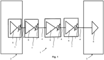
- Fig. 1 illustrates an example section 1 of an optical fiber network.
- the network is a wavelength-division multiplexing (WDM) Network.
- WDM wavelength-division multiplexing
- an ingress WDM node 2 is connected to an egress WDM node 3 via spans 4 of optical fiber.
- the spans 4 of optical fiber are coupled via optical amplifiers 5.
- An amplifier 5 in the ingress node 2 is optically coupled to the first span 4 of optical fiber.
- An amplifier 5 in the egress node 3 is optically coupled to the final span 4 of optical fiber.
- the optical amplifiers 5 shown in Fig. 1 are optical amplifiers with independent gain and output power controls and amplifier noise figure dependence on amplifier gain.
- Fig. 1 also shows variable-gain amplifier 6 and corresponding variable optical attenuators (VOA) 7, wherein the output power is respectively controlled using the respective variable optical attenuator 7.
- VOA variable optical attenuators
- the actual amplifier 6 and the variable optical attenuator 7 are respectively shown being separated from each other.
- each optical amplifier with independent gain and output power control may also be an amplifier in which a variable attenuator is integrated.
- the optical amplifiers 5 can for example be erbium-doped fiber amplifiers (EDFAs) which ensure that the amplifier operates with the lowest possible noise figure regardless of the launch power.
- EDFAs erbium-doped fiber amplifiers
- the optical amplifiers 5 can for example also be hybrid Raman-EDFAs, in particular amplifiers comprised of a combination of a Raman amplifier connected to the input of an EDFA, wherein the Raman amplifier can be discrete or distributed. Therein, one or both amplifier stages could also be semiconductor amplifiers.
- the optimization of the launch power is important to optimize the performance of the network.
- known methods to determine the optimum launch power are based on a simplified optimization approach, wherein the noise figure of the optical amplifiers is assumed to be constant regardless of the amplifier gain value used to compensate the span loss, regardless of the tilt setting the amplifier, and assumed to be constant for all channels.
- this over-simplification leads to an error in the estimation of the optimum launch power, in particular as there are optical amplifiers known with independent gain and output power controls. Therefore, there is a need for a method for optimizing performance of a multi-span optical fiber network, wherein the determination of the optimum launch power is as precise as possible.
- Fig. 2 illustrates a system 10 that includes a network control device 11 for optimizing performance of a multi-span optical fiber network according to embodiments of the invention.
- the multi-span optical fiber network comprises a section 1 of an optical fiber network as shown in Fig. 1 , wherein the same elements as in Fig. 1 are given the same reference numbers as in Fig. 1 and are not discussed in any further detail here.
- the system 10 further comprises a network control device 11, wherein the network control device 11 comprises a computing means 12 which is configured to, for each span, compute an amplifier noise figure and a non-linear noise generated in the span based on information about the span and to use the computed amplifier noise figure and the computed non-linear noise to compute an optimum launch power, and an optimizing means 13 which is configured to optimize performance of the multi-span optical fiber network based on the computed optimum launch powers of all spans.
- the network control device 11 comprises a computing means 12 which is configured to, for each span, compute an amplifier noise figure and a non-linear noise generated in the span based on information about the span and to use the computed amplifier noise figure and the computed non-linear noise to compute an optimum launch power
- an optimizing means 13 which is configured to optimize performance of the multi-span optical fiber network based on the computed optimum launch powers of all spans.
- the parameters and, in particular, that the amplifier noise figure and a non-linear noise generated in each span are computed means that these parameters, respectively information characterizing the parameters are derived respectively calculated by methods of functional analysis and numerical mathematics.
- a network control device 11 for optimizing a multi-span optical fiber network which is as precise as possible, as all relevant parameters that can impact the value of the optimum launch power are taken into account.
- the amplifier noise figure is not assumed to be constant but for each span information characterizing the amplifier noise figure is defined.
- the information about the span preferably includes all relevant parameters of the fiber and information about components which can impact the value of the optimum launch power.
- a global transmission fiber line optimization problem can be reduced to a local per span optimization problem, which makes the optimization numerically very fast, while supporting multi-span transmission fiber lines with different types of fiber in different spans. Therefore, the network control device also addresses the problem that communication systems often evolve and grow during their lifetime, wherein, due to their evolution and growth, these infrastructures often combine different technologies which can produce optical fiber transmission lines that are span-wise heterogeneous.
- the information about the span includes a span length, information about the associated transmission fiber, information about an optical amplifier associated with a previous span, a symbol rate of a corresponding transceiver and a frequency spacing between channels transmitted on the previous span.
- the optimizing means 13 further comprises a controlling means 14 which is configured to separately optimize the performance of each span by setting the gain of an amplifier associated with a particular span and the output power of an amplifier associated with a span that is immediately preceding the particular span based on the computed optimum launch power of the particular span.
- a controlling means 14 which is configured to separately optimize the performance of each span by setting the gain of an amplifier associated with a particular span and the output power of an amplifier associated with a span that is immediately preceding the particular span based on the computed optimum launch power of the particular span.
- the computing means 12 is configured to use linear equivalents of the information about the span to compute the amplifier noise figure.
- the network control device 11 is further configured to optimize the performance of the multi-span optical fiber network during a planning phase of a network deployment.
- the planning phase is a phase during the network planning and design, in which it is, among others, determined whether a predefined system infrastructure, sites, and an operational environment can support a proposed system.
- the network control device further comprises a memory 15 in which usual values for the information about the span are stored. That usual values are chosen for the information about the span means that the values are chosen in such a way that they are common for a comparable usual span, respectively that either design or manufacturing data is chosen for the values. For example, a dependence between noise figure and gain can be chosen that represents a usual amplifier of the same type. Further, the values may be provided by a carrier to a system vendor during design stage.
- pairs of nodes of the network are associated with distinct bands of optical channels used for communication between the pairs of nodes.
- the network control device 11 according to the embodiments of Fig. 2 is, in particular, configured to, during a planning phase of a network deployment, calculate a maximum generalized optical signal-to-noise ratio for the central channel based on the computed optimum launch powers of all spans of the central channel and to use the maximum generalized optical signal-to-noise ratio of the central channel to optimize the performance of the multi-span optical fiber network.
- the network control device 11 is further configured to optimize the performance of the multi-span optical fiber network as part of a network turn-up and commissioning.
- network turn-up and commissioning means the phase after the system equipment has been deployed, during which a series of steps are taken to prove that the system actually meets the specific requirements.
- the network control device 11 further comprises a first determining means 16 which is configured to determine exact values for the information about the span.
- the network control device 11 is configured to, during network turn-up and commissioning, separately calculate a maximum generalized signal-to-noise ratio for each channel based on the computed optimum launch powers of all spans of the respective channel.
- the network control device further comprises a second determining means 17 to determine a worst generalized optical signal-to-noise ratio from the calculated maximum generalized optical signal-to-noise ratios of the channels, wherein the optimizing means 14 is configured to use the worst generalized optical signal-to-noise ratio to optimize the performance of the multi-span optical fiber network.
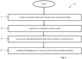
- Fig. 3 illustrates a flowchart of a method 20 for optimizing performance of a multi-span optical fiber network according to a first embodiment of the invention.
- Fig. 3 shows a method 20 for optimizing performance of a multi-span optical fiber network, wherein each span has an associated optical transmission fiber connected to an associated optical amplifier, wherein gain and output power of the associated optical amplifier are respectively controlled independently, and wherein an amplifier noise figure respectively depends on the gain of the associated optical amplifier, wherein each associated optical amplifier is further connected to launch optical signals into a remainder of a corresponding optical transmission line.
- the method 20 comprises the steps of, for each span, computing the amplifier noise figure and computing non-linear noise generated in the span based on information about the span 21 and using the computed amplifier noise figure and the computed non-linear noise to compute an optimum launch power 22, and, optimizing performance of the multi-span optical fiber network based on the computed optimum launch powers of all spans.
- gain and output power of the associated optical amplifier are respectively controlled independently, wherein an amplifier noise figure respectively depends on the gain of the associated optical amplifier
- the associated optical amplifier is an optical associated amplifier with independent gain and output power controls and amplifier noise figure dependence on amplifier gain.
- the control of the output power can be integrated in the optical amplifier but can also be established independently of the optical amplifier.
- the parameters and, in particular, that the amplifier noise figure and a non-linear noise generated in each span are computed means that these parameters, respectively information characterizing the parameters are derived respectively calculated by methods of functional analysis and numerical mathematics.
- the information about the span includes a span length, information about the associated transmission fiber, information about an optical amplifier associated with a previous span, a symbol rate of a corresponding transceiver and a frequency spacing between channels transmitted on the previous span.
- the information about the span includes the following variables: amplifier gain respectively the amplifier gain dependence on signal power G i (dB), amplifier noise figure NF i (dB), fiber span loss in the ith-span Loss i (dB), channel power into the span optical power P i (dBm), the max output power level respectively the signal max power per channel P max_per_chi and ASE noise power P ase, i (dBm) (scaled to 0.1nm/12.5GHz bandwidth).
- the spans and the optical amplifier devices are indexed by the index i, with N representing the total number of spans of optical fiber.
- the max output power level depends on the amplifier type.
- the factor (G i - 1) was replaced by G i for simplicity.
- the noise figure for usual amplifiers depends on the gain, wherein a 3rd order polynomial gain expression can be used for the dependency, wherein the polynomial coefficients are fitted for each amplifier type separately.
- the polynomial coefficients are obtained in several steps of amplifier measurement characterization, wherein first the noise figure is characterized at fixed amplifier gain and tilt over an amplifier bandwidth over multiple modules. Then, for each module, the worst respectively maximum value of the noise figure is identified at some wavelength and the worst values are averaged over all characterized modules and result in a single worst value at fixed gain and tilt.
- characterization data of a resulting plot of noise figure versus gain is fitted with a cubic polynomial with specific coefficients, which depend on the amplifier type.
- the optimum launch power is then obtained by taking the first derivative of the inverse generalized optical signal-to-noise ratio with respect to the signal power P i and equating the result to zero, wherein the spans and the optical amplifier devices are indexed by the index i, with N representing the total number of spans of optical fiber.
- GOSNR i GOSNR i
- OSNR i OSNR i
- VAR NLI normalized nonlinear variance
- NF is a nested function of the signal power.
- the impact of the amplifier output tilt on the noise figure and its impact on channel optimization could be taken into account by replacing the variable gain G(dB) in formula (9a) with gain_caldB G cal,i, which depends on both the gain in decibel units and the tilt via the tilt dependence function TiltdB, which depends, among others, on the channel input signal power averaged over the channel plan.
- the computed optimum launch power is used to calculate a maximum generalized optical signal-to-noise ratio of the span in step 23.
- the maximum generalized optical signal-to-noise ratios of all spans can then be used in step 24 to optimize the performance of the multi-span optical fiber network.
- the maximum generalized optical signal-to-noise ratio results in the optimization of signal primary measurable characteristics, as the maximization of the signal-to-noise ratio and the parameter Q, as well as the minimization of the bit-error rate BER.
Landscapes
- Engineering & Computer Science (AREA)
- Physics & Mathematics (AREA)
- Electromagnetism (AREA)
- Computer Networks & Wireless Communication (AREA)
- Signal Processing (AREA)
- Quality & Reliability (AREA)
- Computing Systems (AREA)
- Optical Communication System (AREA)
Claims (12)
- Verfahren zum Optimieren der Leistung eines faseroptischen Netzwerks mit mehreren Abschnitten, wobei jeder Abschnitt eine zugehörige optische Übertragungsfaser aufweist, die mit einem zugehörigen optischen Verstärker verbunden ist, wobei der Gain und die Ausgangsleistung des zugehörigen optischen Verstärkers jeweils unabhängig gesteuert werden und wobei eine Rauschzahl eines Verstärkers jeweils von dem Gain des zugehörigen optischen Verstärkers abhängt, wobei jeder zugehörige optische Verstärker ferner so angeschlossen ist, dass er optische Signale in einen verbleibenden Teil einer entsprechenden optischen Übertragungsleitung einspeist, dadurch gekennzeichnet, dass das Verfahren (20) die folgenden Schritte umfasst:- Berechnen der Verstärkerrauschzahl und eines in dem Abschnitt erzeugten nichtlinearen Rauschens für jeden Abschnitt auf der Grundlage von Informationen über den Abschnitt (21) und Verwenden der berechneten Verstärkerrauschzahl und des berechneten nichtlinearen Rauschens zum Berechnen einer in den Abschnitt einzuspeisenden optimalen Einspeiseleistung (22); und- die Optimierung der Leistung des faseroptischen Netzwerks mit mehreren Abschnitten auf der Grundlage der berechneten optimalen Einspeiseleistung aller Abschnitte (23,24),wobei der Schritt des Optimierens der Leistung des faseroptischen Netzwerks mit mehreren Abschnitten auf der Grundlage der berechneten optimalen Einspeiseleistung aller Abschnitte zudem den folgenden Schritt umfasst:- getrenntes Optimieren der Leistung jedes Abschnitts durch Einstellen des Gains eines Verstärkers, der einem bestimmten Abschnitt zugeordnet ist, und der Ausgangsleistung eines Verstärkers, der einem Abschnitt zugeordnet ist, der dem bestimmten Abschnitt unmittelbar vorausgeht, auf der Grundlage der berechneten optimalen Einspeiseleistung des bestimmten Abschnitts, wobei der Gain des Verstärkers, der dem bestimmten Abschnitt zugeordnet ist, auf der Grundlage eines optimalen Gains eingestellt wird, die von der berechneten optimalen Einspeiseleistung des bestimmten Abschnitts abgeleitet wird.
- Verfahren nach Anspruch 1, wobei die Informationen über den Abschnitt folgende Elemente aufweisen: eine Abschnittslänge, Informationen über die zugehörige Übertragungsfaser, Informationen über einen optischen Verstärker, der einem vorherigen Abschnitt zugeordnet ist, eine Symbolrate eines entsprechenden Transceivers und einen Frequenzabstand zwischen Kanälen, die auf dem vorherigen Abschnitt übertragen wurden.
- Verfahren nach Anspruch 1 oder 2, wobei der Schritt des Optimierens der Leistung des faseroptischen Netzwerks mit mehreren Abschnitten auf der Grundlage der berechneten optimalen Einspeiseleistungen aller Abschnitte zudem (23, 24) die folgenden Schritte umfasst:- die Verwendung der berechneten optimalen Einspeiseleistung für jeden Abschnitt, um ein maximales verallgemeinertes optisches Signal-Rausch-Verhältnis (GOSNR) des Abschnitts (23) zu berechnen; und- Verwendung der berechneten maximalen verallgemeinterten optischen Signal-Rausch-Verhältnisse (GOSNR) aller Abschnitte zur Optimierung der Leistung des faseroptischen Netzwerks mit mehreren Abschnitten (24).
- Verfahren nach einem der Ansprüche 1 bis 3, wobei lineare Äquivalente der Information über den Abschnitt zur Berechnung der Rauschzahl des Verstärkers verwendet werden.
- Verfahren nach einem der Ansprüche 1 bis 4, wobei die Leistung des faseroptischen Netzwerks mit mehreren Abschnitten während einer Planungsphase einer Netzwerkbereitstellung optimiert wird, wobei übliche Werte für die Informationen über den Abschnitt gewählt werden, und wobei optional in dem faseroptischen Netzwerk mit mehreren Abschnitten Knotenpaare des Netzes verschiedenen Bändern von optischen Kanälen zugeordnet sind, die zur Kommunikation zwischen den Knotenpaaren dienen, wobei ein maximales verallgemeinertes optisches Signal-Rausch-Verhältnis (GOSNR) für den zentralen Kanal auf der Grundlage der berechneten optimalen Einspeiseleistungen aller Abschnitte des zentralen Kanals berechnet wird, und wobei das maximale verallgemeinerte optische Signal-Rausch-Verhältnis (GOSNR) des zentralen Kanals verwendet wird, um die Leistung des faseroptischen Netzwerks mit mehreren Abschnitten zu optimieren.
- Verfahren nach einem der Ansprüche 1 bis 5, wobei die Leistung des faseroptischen Netzwerks mit mehreren Abschnitten als Teil eines Netzwerk Turn-Ups und einer Inbetriebnahme optimiert wird, wobei exakte Werte für die Informationen über den Abschnitt gewählt werden, und wobei optional in dem faseroptischen Netzwerk mit mehreren Abschnitten Paare von Knoten des Netzes mit verschiedenen Bändern von optischen Kanälen assoziiert sind, die zur Kommunikation zwischen den Knotenpaaren dienen, wobei ein maximales verallgemeinertes optisches Signal-Rausch-Verhältnis (GOSNR) für jeden Kanal separat berechnet wird, basierend auf den berechneten optimalen Einspeiseleistungen aller Abschnitte des jeweiligen Kanals, wobei ein schlechtestes verallgemeinertes optisches Signal-Rausch-Verhältnis (GOSNR) aus den berechneten maximalen verallgemeinerten optischen Signal-Rausch-Verhältnissen (GOSNR) der Kanäle bestimmt wird, und wobei das schlechteste verallgemeinerte optische Signal-Rausch-Verhältnis (GOSNR) verwendet wird, um die Leistung des faseroptischen Netzwerks mit mehreren Abschnitten zu optimieren.
- Netzwerksteuervorrichtung zur Optimierung der Leistung eines faseroptischen Netzwerks mit mehreren Abschnitten, bei dem jeder Abschnitt (4) eine zugehörige optische Übertragungsfaser hat, die mit einem zugehörigen optischen Verstärker (5) verbunden ist, wobei Gain und Ausgangsleistung des zugehörigen optischen Verstärkers (5) jeweils unabhängig gesteuert werden, und wobei eine Verstärkerrauschzahl jeweils von dem Gain des zugehörigen optischen Verstärkers (5) abhängt, wobei jeder zugehörige optische Verstärker (5) zudem so angeschlossen ist, dass er optische Signale in einen verbleibenden Teil einer entsprechenden optischen Übertragungsleitung einspeist, dadurch gekennzeichnet, dass die Netzwerksteuerung (11) ein Rechenmittel (12) aufweist, das so konfiguriert ist, dass es für jeden Abschnitt (4) die Verstärkerrauschzahl und ein in dem Abschnitt (4) erzeugtes nichtlineares Rauschen auf der Grundlage von Informationen über den Abschnitt berechnet und die berechnete Verstärkerrauschzahl und das berechnete nichtlineare Rauschen verwendet, um eine in den Abschnitt einzuspeisende optimale Einspeiseleistung zu berechnen, und ein Optimierungsmittel (13), das so konfiguriert ist, dass es die Leistung des faseroptischen Netzwerks mit mehreren Abschnitten auf der Grundlage der berechneten optimalen Einspeiseleistungen für alle Abschnitte (4) optimiert, wobei das Optimierungsmittel (13) ein Steuermittel (14) aufweist, das so konfiguriert ist, dass es die Leistung jedes Abschnitts gesondert optimiert, indem es den Gain eines Verstärkers, der einem bestimmten Abschnitt zugeordnet ist, und die Ausgangsleistung eines Verstärkers, der einem Abschnitt zugeordnet ist, der dem bestimmten Abschnitt unmittelbar vorausgeht, auf der Grundlage der berechneten optimalen Einspeiseleistung des bestimmten Abschnitts einstellt, wobei das Steuermittel (14) so konfiguriert ist, dass es den Gain des Verstärkers, der dem bestimmten Abschnitt zugeordnet ist, auf der Grundlage eines optimalen Gains einstellt, der von der berechneten optimalen Einspeiseleistung des bestimmten Abschnitts abgeleitet ist.
- Netzwerksteuervorrichtung nach Anspruch 7, wobei die Informationen über den Abschnitt Folgendes umfasst: eine Abschnittslänge, Informationen über die zugehörige Übertragungsfaser, Informationen über einen optischen Verstärker, der einem vorherigen Abschnitt zugeordnet ist, eine Symbolrate eines entsprechenden Transceivers und einen Frequenzabstand zwischen Kanälen, die auf dem vorherigen Abschnitt übertragen wurden.
- Netzwerksteuervorrichtung nach Anspruch 7 oder 8, wobei das Optimierungsmittel zudem ein Kalkulationsmittel aufweist, das so konfiguriert ist, dass es für jeden Abschnitt die berechnete optimale Einspeiseleistung verwendet, um ein maximales verallgemeinertes optisches Signal-Rausch-Verhältnis (GOSNR) des Abschnitts zu berechnen, und wobei das Optimierungsmittel so konfiguriert ist, dass es die berechneten maximalen verallgemeinerten optischen Signal-Rausch-Verhältnisse (GOSNR) aller Abschnitte verwendet, um die Leistung des faseroptischen Netzwerks mit mehreren Abschnitten zu optimieren.
- Netzwerksteuervorrichtung nach einem der Ansprüche 7 bis 9, wobei das Computermittel (12) so konfiguriert ist, dass es lineare Äquivalente der Informationen über den Abschnitt verwendet, um die Verstärkerrauschzahl zu berechnen.
- Netzwerksteuervorrichtung nach einem der Ansprüche 7 bis 10, wobei die Netzwerksteuervorrichtung (11) so konfiguriert ist, dass sie die Leistung des faseroptischen Netzwerks mit mehreren Abschnitten während einer Planungsphase einer Netzwerkbereitstellung optimiert, wobei die Netzwerksteuervorrichtung (11) zudem einen Datenspeicher (15) aufweist, in dem übliche Werte für die Informationen über den Abschnitt gespeichert sind, und wobei optional in dem faseroptischen Netzwerk Knotenpaare des Netzes verschiedenen Bändern für optische Kanäle zugeordnet sind, die zur Kommunikation zwischen den Knotenpaaren dienen, wobei die Netzwerksteuervorrichtung (11) so konfiguriert ist, dass sie ein maximales verallgemeinertes optisches Signal-Rausch-Verhältnis (GOSNR) für den zentralen Kanal auf der Grundlage der berechneten optimalen Einspeiseleistungen aller Abschnitte (4) des zentralen Kanals berechnet und das maximale verallgemeinerte optische Signal-Rausch-Verhältnis (GOSNR) des zentralen Kanals verwendet, um die Leistung des faseroptischen Netzwerks mit mehreren Abschnitten zu optimieren.
- Netzwerksteuervorrichtung nach einem der Ansprüche 7 bis 11, wobei die Netzwerksteuervorrichtung (11) so konfiguriert ist, dass sie die Leistung des faseroptischen Netzwerks mit mehreren Abschnitten als Teil eines Netzwerk Turn-Ups und Inbetriebnahme optimiert, wobei die Netzwerksteuervorrichtung (11) zudem ein erstes Bestimmungsmittel (16) aufweist, das so konfiguriert ist, dass es genaue Werte für die Informationen über den Abschnitt bestimmt, und wobei optional in dem faseroptischen Netzwerk mit mehreren Abschnitten Knotenpaare des Netzes verschiedenen Bändern von optischen Kanälen zugeordnet sind, die zur Kommunikation zwischen den Knotenpaaren dienen, wobei die Netzwerksteuerung so konfiguriert ist, dass sie auf der Grundlage der berechneten optimalen Einspeiseleistungen aller Abschnitte (4) des jeweiligen Kanals separat ein maximales verallgemeinertes Signal-Rausch-Verhältnis (GOSNR) für jeden Kanal berechnet, wobei die Netzwerksteuervorrichtung (11) zudem zweite Bestimmungsmittel (17) aufweist, die dazu dienen, ein schlechtes verallgemeinertes optisches Signal-Rausch-Verhältnis (GOSNR) aus den berechneten maximalen verallgemeinerten optischen Signal-Rausch-Verhältnissen (GOSNR) der Kanäle zu bestimmen, und wobei das Optimierungsmittel (13) so konfiguriert ist, dass es das schlechteste verallgemeinerte optische Signal-Rausch-Verhältnis (GOSNR) verwendet, um die Leistung des faseroptischen Netzwerks mit mehreren Abschnitten zu optimieren.
Applications Claiming Priority (1)
| Application Number | Priority Date | Filing Date | Title |
|---|---|---|---|
| US17/063,224 US11489597B2 (en) | 2020-10-05 | 2020-10-05 | Method and network control device for optimizing performance of a multi-span optical fiber network |
Publications (2)
| Publication Number | Publication Date |
|---|---|
| EP3979522A1 EP3979522A1 (de) | 2022-04-06 |
| EP3979522B1 true EP3979522B1 (de) | 2025-02-26 |
Family
ID=78078001
Family Applications (1)
| Application Number | Title | Priority Date | Filing Date |
|---|---|---|---|
| EP21200438.6A Active EP3979522B1 (de) | 2020-10-05 | 2021-10-01 | Verfahren und netzwerksteuerungsvorrichtung zur optimierung der leistung eines optischen mehrspann-fasernetzwerks |
Country Status (2)
| Country | Link |
|---|---|
| US (1) | US11489597B2 (de) |
| EP (1) | EP3979522B1 (de) |
Families Citing this family (6)
| Publication number | Priority date | Publication date | Assignee | Title |
|---|---|---|---|---|
| US20240388363A1 (en) * | 2021-04-08 | 2024-11-21 | Danmarks Tekniske Universitet | Spatially distributed optical fibre based transmission link and method thereof |
| JP7756045B2 (ja) * | 2022-04-28 | 2025-10-17 | 1Finity株式会社 | 光伝送装置、光伝送システム、および送信光パワー制御方法 |
| CN114915344B (zh) * | 2022-07-19 | 2022-10-04 | 北京中昱光通科技有限公司 | 一种掺铒光纤放大器的设计方法及系统 |
| US12476712B2 (en) * | 2023-09-08 | 2025-11-18 | Huawei Technologies Co., Ltd. | Method and device for monitoring generalized optical signal-to-noise ratio, coherent receiver and network apparatus |
| JP7846069B2 (ja) * | 2023-09-21 | 2026-04-14 | Kddi株式会社 | 光通信システムの制御装置及びプログラム |
| US20260031908A1 (en) | 2024-07-29 | 2026-01-29 | Adtran Networks Se | Method and Network Control Device for Computing a Set of Optimal Amplification Parameters for a Span of a Multi-Span Optical Fiber Network |
Family Cites Families (4)
| Publication number | Priority date | Publication date | Assignee | Title |
|---|---|---|---|---|
| JPH11122192A (ja) | 1997-10-17 | 1999-04-30 | Fujitsu Ltd | 光増幅器及び該光増幅器を備えた光通信システム |
| US9641252B2 (en) * | 2012-08-03 | 2017-05-02 | Telefonaktiebolaget Lm Ericsson (Publ) | Method of optimizing optical signal quality in an optical communications link, optical network element and optical communications link |
| WO2014177224A1 (en) | 2013-05-03 | 2014-11-06 | Huawei Technologies Co.,Ltd. | Method for assigning launch powers to an arrangement of physically coupled fiber spans |
| US10439751B2 (en) | 2017-05-24 | 2019-10-08 | Ciena Corporation | Power control in an optical fiber network |
-
2020
- 2020-10-05 US US17/063,224 patent/US11489597B2/en active Active
-
2021
- 2021-10-01 EP EP21200438.6A patent/EP3979522B1/de active Active
Also Published As
| Publication number | Publication date |
|---|---|
| EP3979522A1 (de) | 2022-04-06 |
| US11489597B2 (en) | 2022-11-01 |
| US20220109509A1 (en) | 2022-04-07 |
Similar Documents
| Publication | Publication Date | Title |
|---|---|---|
| US11489597B2 (en) | Method and network control device for optimizing performance of a multi-span optical fiber network | |
| US6934479B2 (en) | Wavelength division multiplexing optical communication system and wavelength division multiplexing optical communication method | |
| EP1214760B1 (de) | Optisches übertragungssystem mit optischem verstärker und dessen betrieb | |
| US8620160B2 (en) | Optical transmission apparatus | |
| US9641252B2 (en) | Method of optimizing optical signal quality in an optical communications link, optical network element and optical communications link | |
| JP2003124881A (ja) | 光伝送装置および光伝送システム | |
| US20250132829A1 (en) | Optical power control device, optical power control method, and optical transmission system | |
| JP7756045B2 (ja) | 光伝送装置、光伝送システム、および送信光パワー制御方法 | |
| US8767285B2 (en) | Method and apparatus for channel power depletion compensation for hybrid distributed Raman amplifier-Erbium doped fiber amplifier | |
| Fei et al. | Estimating EDFA output power with an efficient numerical modeling framework | |
| US20070058984A1 (en) | Network management system for an optical network | |
| US11990988B2 (en) | Optical transmission system and optical transmission device | |
| US20050249505A1 (en) | Spectral tilt measurement system and method for an optical medium | |
| Rapp | Amplifiers in multi–band scenarios—output power requirements, control and performance characteristics | |
| Sambo et al. | Multiband seamless network upgrade by exploiting the E-band | |
| US20060233552A1 (en) | Method for preemphasising an optical multiplex signal | |
| US7006278B2 (en) | Wavelength-division multiplexing optical transmission system and repeater station therein | |
| US12155415B2 (en) | Method for reducing the impact of transient effects in an optical network | |
| US7280762B1 (en) | Optical communication system having dynamic gain equalization | |
| Souza et al. | Service-aware genetic algorithm for link power control in multi-band optical transmission systems | |
| EP4687312A1 (de) | Verfahren und netzwerksteuerungsvorrichtung zur berechnung eines satzes optimaler verstärkungsparameter für eine spannweite eines glasfasernetzwerks mit mehreren spannweiten | |
| CN116569500A (zh) | 用于评估光纤链路的非线性损伤的方法和装置 | |
| US20250141584A1 (en) | Optical transmission device, optical transmission method, and optical transmission system | |
| Chen et al. | Global Power and OSNR Analyses for Super C band Optical Transmission Systems | |
| US20250293771A1 (en) | Optical line physical parameters calibation in presence of edfa total power monitors |
Legal Events
| Date | Code | Title | Description |
|---|---|---|---|
| PUAI | Public reference made under article 153(3) epc to a published international application that has entered the european phase |
Free format text: ORIGINAL CODE: 0009012 |
|
| STAA | Information on the status of an ep patent application or granted ep patent |
Free format text: STATUS: THE APPLICATION HAS BEEN PUBLISHED |
|
| AK | Designated contracting states |
Kind code of ref document: A1 Designated state(s): AL AT BE BG CH CY CZ DE DK EE ES FI FR GB GR HR HU IE IS IT LI LT LU LV MC MK MT NL NO PL PT RO RS SE SI SK SM TR |
|
| STAA | Information on the status of an ep patent application or granted ep patent |
Free format text: STATUS: REQUEST FOR EXAMINATION WAS MADE |
|
| 17P | Request for examination filed |
Effective date: 20221006 |
|
| RBV | Designated contracting states (corrected) |
Designated state(s): AL AT BE BG CH CY CZ DE DK EE ES FI FR GB GR HR HU IE IS IT LI LT LU LV MC MK MT NL NO PL PT RO RS SE SI SK SM TR |
|
| RAP3 | Party data changed (applicant data changed or rights of an application transferred) |
Owner name: ADTRAN NETWORKS SE |
|
| GRAP | Despatch of communication of intention to grant a patent |
Free format text: ORIGINAL CODE: EPIDOSNIGR1 |
|
| STAA | Information on the status of an ep patent application or granted ep patent |
Free format text: STATUS: GRANT OF PATENT IS INTENDED |
|
| INTG | Intention to grant announced |
Effective date: 20240919 |
|
| GRAS | Grant fee paid |
Free format text: ORIGINAL CODE: EPIDOSNIGR3 |
|
| GRAA | (expected) grant |
Free format text: ORIGINAL CODE: 0009210 |
|
| STAA | Information on the status of an ep patent application or granted ep patent |
Free format text: STATUS: THE PATENT HAS BEEN GRANTED |
|
| AK | Designated contracting states |
Kind code of ref document: B1 Designated state(s): AL AT BE BG CH CY CZ DE DK EE ES FI FR GB GR HR HU IE IS IT LI LT LU LV MC MK MT NL NO PL PT RO RS SE SI SK SM TR |
|
| REG | Reference to a national code |
Ref country code: GB Ref legal event code: FG4D |
|
| REG | Reference to a national code |
Ref country code: CH Ref legal event code: EP |
|
| REG | Reference to a national code |
Ref country code: DE Ref legal event code: R096 Ref document number: 602021026696 Country of ref document: DE |
|
| REG | Reference to a national code |
Ref country code: IE Ref legal event code: FG4D |
|
| P01 | Opt-out of the competence of the unified patent court (upc) registered |
Free format text: CASE NUMBER: APP_13603/2025 Effective date: 20250319 |
|
| REG | Reference to a national code |
Ref country code: NL Ref legal event code: MP Effective date: 20250226 |
|
| PG25 | Lapsed in a contracting state [announced via postgrant information from national office to epo] |
Ref country code: RS Free format text: LAPSE BECAUSE OF FAILURE TO SUBMIT A TRANSLATION OF THE DESCRIPTION OR TO PAY THE FEE WITHIN THE PRESCRIBED TIME-LIMIT Effective date: 20250526 |
|
| PG25 | Lapsed in a contracting state [announced via postgrant information from national office to epo] |
Ref country code: FI Free format text: LAPSE BECAUSE OF FAILURE TO SUBMIT A TRANSLATION OF THE DESCRIPTION OR TO PAY THE FEE WITHIN THE PRESCRIBED TIME-LIMIT Effective date: 20250226 |
|
| PG25 | Lapsed in a contracting state [announced via postgrant information from national office to epo] |
Ref country code: PL Free format text: LAPSE BECAUSE OF FAILURE TO SUBMIT A TRANSLATION OF THE DESCRIPTION OR TO PAY THE FEE WITHIN THE PRESCRIBED TIME-LIMIT Effective date: 20250226 |
|
| PG25 | Lapsed in a contracting state [announced via postgrant information from national office to epo] |
Ref country code: ES Free format text: LAPSE BECAUSE OF FAILURE TO SUBMIT A TRANSLATION OF THE DESCRIPTION OR TO PAY THE FEE WITHIN THE PRESCRIBED TIME-LIMIT Effective date: 20250226 |
|
| REG | Reference to a national code |
Ref country code: LT Ref legal event code: MG9D |
|
| PG25 | Lapsed in a contracting state [announced via postgrant information from national office to epo] |
Ref country code: IS Free format text: LAPSE BECAUSE OF FAILURE TO SUBMIT A TRANSLATION OF THE DESCRIPTION OR TO PAY THE FEE WITHIN THE PRESCRIBED TIME-LIMIT Effective date: 20250626 Ref country code: NO Free format text: LAPSE BECAUSE OF FAILURE TO SUBMIT A TRANSLATION OF THE DESCRIPTION OR TO PAY THE FEE WITHIN THE PRESCRIBED TIME-LIMIT Effective date: 20250526 |
|
| PG25 | Lapsed in a contracting state [announced via postgrant information from national office to epo] |
Ref country code: NL Free format text: LAPSE BECAUSE OF FAILURE TO SUBMIT A TRANSLATION OF THE DESCRIPTION OR TO PAY THE FEE WITHIN THE PRESCRIBED TIME-LIMIT Effective date: 20250226 |
|
| PG25 | Lapsed in a contracting state [announced via postgrant information from national office to epo] |
Ref country code: HR Free format text: LAPSE BECAUSE OF FAILURE TO SUBMIT A TRANSLATION OF THE DESCRIPTION OR TO PAY THE FEE WITHIN THE PRESCRIBED TIME-LIMIT Effective date: 20250226 |
|
| PG25 | Lapsed in a contracting state [announced via postgrant information from national office to epo] |
Ref country code: PT Free format text: LAPSE BECAUSE OF FAILURE TO SUBMIT A TRANSLATION OF THE DESCRIPTION OR TO PAY THE FEE WITHIN THE PRESCRIBED TIME-LIMIT Effective date: 20250626 Ref country code: LV Free format text: LAPSE BECAUSE OF FAILURE TO SUBMIT A TRANSLATION OF THE DESCRIPTION OR TO PAY THE FEE WITHIN THE PRESCRIBED TIME-LIMIT Effective date: 20250226 |
|
| PG25 | Lapsed in a contracting state [announced via postgrant information from national office to epo] |
Ref country code: GR Free format text: LAPSE BECAUSE OF FAILURE TO SUBMIT A TRANSLATION OF THE DESCRIPTION OR TO PAY THE FEE WITHIN THE PRESCRIBED TIME-LIMIT Effective date: 20250527 Ref country code: BG Free format text: LAPSE BECAUSE OF FAILURE TO SUBMIT A TRANSLATION OF THE DESCRIPTION OR TO PAY THE FEE WITHIN THE PRESCRIBED TIME-LIMIT Effective date: 20250226 |
|
| REG | Reference to a national code |
Ref country code: AT Ref legal event code: MK05 Ref document number: 1771701 Country of ref document: AT Kind code of ref document: T Effective date: 20250226 |
|
| PG25 | Lapsed in a contracting state [announced via postgrant information from national office to epo] |
Ref country code: SE Free format text: LAPSE BECAUSE OF FAILURE TO SUBMIT A TRANSLATION OF THE DESCRIPTION OR TO PAY THE FEE WITHIN THE PRESCRIBED TIME-LIMIT Effective date: 20250226 |
|
| PG25 | Lapsed in a contracting state [announced via postgrant information from national office to epo] |
Ref country code: SM Free format text: LAPSE BECAUSE OF FAILURE TO SUBMIT A TRANSLATION OF THE DESCRIPTION OR TO PAY THE FEE WITHIN THE PRESCRIBED TIME-LIMIT Effective date: 20250226 |
|
| PG25 | Lapsed in a contracting state [announced via postgrant information from national office to epo] |
Ref country code: DK Free format text: LAPSE BECAUSE OF FAILURE TO SUBMIT A TRANSLATION OF THE DESCRIPTION OR TO PAY THE FEE WITHIN THE PRESCRIBED TIME-LIMIT Effective date: 20250226 |
|
| PG25 | Lapsed in a contracting state [announced via postgrant information from national office to epo] |
Ref country code: IT Free format text: LAPSE BECAUSE OF FAILURE TO SUBMIT A TRANSLATION OF THE DESCRIPTION OR TO PAY THE FEE WITHIN THE PRESCRIBED TIME-LIMIT Effective date: 20250226 |
|
| PG25 | Lapsed in a contracting state [announced via postgrant information from national office to epo] |
Ref country code: AT Free format text: LAPSE BECAUSE OF FAILURE TO SUBMIT A TRANSLATION OF THE DESCRIPTION OR TO PAY THE FEE WITHIN THE PRESCRIBED TIME-LIMIT Effective date: 20250226 |
|
| PG25 | Lapsed in a contracting state [announced via postgrant information from national office to epo] |
Ref country code: CZ Free format text: LAPSE BECAUSE OF FAILURE TO SUBMIT A TRANSLATION OF THE DESCRIPTION OR TO PAY THE FEE WITHIN THE PRESCRIBED TIME-LIMIT Effective date: 20250226 Ref country code: EE Free format text: LAPSE BECAUSE OF FAILURE TO SUBMIT A TRANSLATION OF THE DESCRIPTION OR TO PAY THE FEE WITHIN THE PRESCRIBED TIME-LIMIT Effective date: 20250226 |
|
| PG25 | Lapsed in a contracting state [announced via postgrant information from national office to epo] |
Ref country code: RO Free format text: LAPSE BECAUSE OF FAILURE TO SUBMIT A TRANSLATION OF THE DESCRIPTION OR TO PAY THE FEE WITHIN THE PRESCRIBED TIME-LIMIT Effective date: 20250226 |
|
| PG25 | Lapsed in a contracting state [announced via postgrant information from national office to epo] |
Ref country code: SK Free format text: LAPSE BECAUSE OF FAILURE TO SUBMIT A TRANSLATION OF THE DESCRIPTION OR TO PAY THE FEE WITHIN THE PRESCRIBED TIME-LIMIT Effective date: 20250226 |
|
| REG | Reference to a national code |
Ref country code: DE Ref legal event code: R097 Ref document number: 602021026696 Country of ref document: DE |
|
| PLBE | No opposition filed within time limit |
Free format text: ORIGINAL CODE: 0009261 |
|
| STAA | Information on the status of an ep patent application or granted ep patent |
Free format text: STATUS: NO OPPOSITION FILED WITHIN TIME LIMIT |
|
| PGFP | Annual fee paid to national office [announced via postgrant information from national office to epo] |
Ref country code: DE Payment date: 20251020 Year of fee payment: 5 |
|
| PGFP | Annual fee paid to national office [announced via postgrant information from national office to epo] |
Ref country code: GB Payment date: 20251024 Year of fee payment: 5 |
|
| 26N | No opposition filed |
Effective date: 20251127 |