EP3979471A1 - Motor - Google Patents
Motor Download PDFInfo
- Publication number
- EP3979471A1 EP3979471A1 EP20813535.0A EP20813535A EP3979471A1 EP 3979471 A1 EP3979471 A1 EP 3979471A1 EP 20813535 A EP20813535 A EP 20813535A EP 3979471 A1 EP3979471 A1 EP 3979471A1
- Authority
- EP
- European Patent Office
- Prior art keywords
- shaft
- magnet
- disposed
- protrusions
- protrusion
- Prior art date
- Legal status (The legal status is an assumption and is not a legal conclusion. Google has not performed a legal analysis and makes no representation as to the accuracy of the status listed.)
- Granted
Links
Images











Classifications
-
- H—ELECTRICITY
- H02—GENERATION; CONVERSION OR DISTRIBUTION OF ELECTRIC POWER
- H02K—DYNAMO-ELECTRIC MACHINES
- H02K1/00—Details of the magnetic circuit
- H02K1/06—Details of the magnetic circuit characterised by the shape, form or construction
- H02K1/22—Rotating parts of the magnetic circuit
- H02K1/27—Rotor cores with permanent magnets
- H02K1/2706—Inner rotors
- H02K1/272—Inner rotors the magnetisation axis of the magnets being perpendicular to the rotor axis
- H02K1/274—Inner rotors the magnetisation axis of the magnets being perpendicular to the rotor axis the rotor consisting of two or more circumferentially positioned magnets
-
- H—ELECTRICITY
- H02—GENERATION; CONVERSION OR DISTRIBUTION OF ELECTRIC POWER
- H02K—DYNAMO-ELECTRIC MACHINES
- H02K7/00—Arrangements for handling mechanical energy structurally associated with dynamo-electric machines, e.g. structural association with mechanical driving motors or auxiliary dynamo-electric machines
- H02K7/003—Couplings; Details of shafts
-
- H—ELECTRICITY
- H02—GENERATION; CONVERSION OR DISTRIBUTION OF ELECTRIC POWER
- H02K—DYNAMO-ELECTRIC MACHINES
- H02K1/00—Details of the magnetic circuit
- H02K1/06—Details of the magnetic circuit characterised by the shape, form or construction
- H02K1/12—Stationary parts of the magnetic circuit
-
- H—ELECTRICITY
- H02—GENERATION; CONVERSION OR DISTRIBUTION OF ELECTRIC POWER
- H02K—DYNAMO-ELECTRIC MACHINES
- H02K1/00—Details of the magnetic circuit
- H02K1/06—Details of the magnetic circuit characterised by the shape, form or construction
- H02K1/12—Stationary parts of the magnetic circuit
- H02K1/18—Means for mounting or fastening magnetic stationary parts on to, or to, the stator structures
- H02K1/185—Means for mounting or fastening magnetic stationary parts on to, or to, the stator structures to outer stators
-
- H—ELECTRICITY
- H02—GENERATION; CONVERSION OR DISTRIBUTION OF ELECTRIC POWER
- H02K—DYNAMO-ELECTRIC MACHINES
- H02K1/00—Details of the magnetic circuit
- H02K1/06—Details of the magnetic circuit characterised by the shape, form or construction
- H02K1/22—Rotating parts of the magnetic circuit
- H02K1/27—Rotor cores with permanent magnets
- H02K1/2706—Inner rotors
- H02K1/272—Inner rotors the magnetisation axis of the magnets being perpendicular to the rotor axis
- H02K1/274—Inner rotors the magnetisation axis of the magnets being perpendicular to the rotor axis the rotor consisting of two or more circumferentially positioned magnets
- H02K1/2753—Inner rotors the magnetisation axis of the magnets being perpendicular to the rotor axis the rotor consisting of two or more circumferentially positioned magnets the rotor consisting of magnets or groups of magnets arranged with alternating polarity
- H02K1/278—Surface mounted magnets; Inset magnets
-
- H—ELECTRICITY
- H02—GENERATION; CONVERSION OR DISTRIBUTION OF ELECTRIC POWER
- H02K—DYNAMO-ELECTRIC MACHINES
- H02K1/00—Details of the magnetic circuit
- H02K1/06—Details of the magnetic circuit characterised by the shape, form or construction
- H02K1/22—Rotating parts of the magnetic circuit
- H02K1/28—Means for mounting or fastening rotating magnetic parts on to, or to, the rotor structures
-
- H—ELECTRICITY
- H02—GENERATION; CONVERSION OR DISTRIBUTION OF ELECTRIC POWER
- H02K—DYNAMO-ELECTRIC MACHINES
- H02K5/00—Casings; Enclosures; Supports
- H02K5/04—Casings or enclosures characterised by the shape, form or construction thereof
Definitions
- the present invention relates to a motor.
- Motors are apparatuses configured to convert electrical energy to mechanical energy to obtain rotational forces and are widely used for vehicles, home appliances, industrial machines, and the like.
- an electronic power steering (EPS) system in which the motor is used secures turning stability and provides a rapid restoring force by driving the motor according to traveling conditions using an electronic control unit (ECU). Accordingly, a driver of a vehicle can drive safely.
- ECU electronice control unit
- a motor includes a shaft and a stator.
- the shaft may have a hollow shape.
- Magnets may be attached to an outer circumferential surface of the shaft.
- the hollow shaft has a problem of difficulty in aligning positions of the magnets. This is because it is difficult to form guides for aligning the magnets due to a process of machining the hollow shaft. When there are no guides, which guide the magnets, on the shaft, and when the magnets are overmolded, a problem of misalignment of the magnet may occur. In addition, when the magnets are surrounded by a can or adhesive member, there is a risk of movement of the magnet.
- an adhesive is used to fix the magnets to the shaft.
- the adhesive is used, there is a problem in that a long time is required for curing.
- a problem of misalignment of the magnet may occur, and there is a problem in that it is difficult to check the misalignment.
- overmolding since a thickness is large, there is a difficulty in securing a gap with respect to the stator.
- the present invention is directed to providing a motor allowing a magnet disposed on an outer circumferential surface of a hollow shaft to be aligned and fixed.
- the present invention is directed to providing a motor in which a gap between a magnet and a stator is reduced, of which a process is simplified, and in which a position of the magnet is checked.
- One aspect of the present invention provides a motor including a stator, a shaft having a hollow and disposed inside the stator, and a magnet disposed on an outer circumferential surface of the shaft, wherein the shaft includes a plurality of protrusions in contact with the magnet, and the plurality of protrusions include first faces protruding from the outer circumferential surface of the shaft and second faces concavely disposed in an inner circumferential surface of the shaft.
- a motor including a stator, a shaft having a hollow and disposed inside the stator, and a magnet disposed on an outer circumferential surface of the shaft, wherein the shaft includes a plurality of second holes passing through an inner side to an outer side of the shaft and a plurality of protrusions which are disposed in the plurality of second holes and of which at least parts protrude from the outer circumferential surface of the shaft and are in contact with the magnet.
- the plurality of protrusions may be disposed to be spaced apart from each other in a circumferential direction of the shaft, and a separation distance between the plurality of protrusions in the circumferential direction may be greater than or equal to a width of the magnet.
- the plurality of protrusions may be disposed to be spaced apart from each other in an axial direction of the shaft, and a separation distance between the protrusions in the axial direction may be smaller than or equal to a length of the magnet.
- One protrusion of the plurality of protrusions may be disposed in an axial direction of the shaft, and a length of the one protrusion in the axial direction may be greater than 1/2 times a length of the magnet.
- Each of the first face and the second face may include at least one flat surface.
- the first face may include a curved surface in contact with the magnet.
- a height from the outer circumferential surface of the shaft to an outer end of the protrusion may be smaller than a height of the magnet in a radial direction of the shaft.
- the shaft may include a first hole which passes from in inner side to an outer side of the shaft, and the protrusion may extend from an edge of the first hole.
- the motor may include a cover disposed outside the magnet, and the cover may include a groove in which the protrusion is disposed.
- Threads may be disposed at a side surface of the protrusion and the second hole.
- a knurling structure may be disposed on the protrusion.
- Still another aspect of the present invention provides a motor including a stator, a shaft disposed inside the stator, a magnet coupled to the shaft, and a cover disposed outside the magnet, wherein the cover includes a first part and a second part extending from one side of the first part, an inner surface of the magnet is in contact with an outer surface of the shaft, an outer surface of the magnet is in contact with an inner surface of the first part, a part of an inner surface of the second part is in contact with the outer surface of the shaft, and the remaining part of the inner surface of the second part is disposed to be spaced apart from the outer surface of the shaft so that a space is disposed between the outer surface of the shaft and the inner surface of the second part.
- the cover may include a third part extending from the other side of the first part, a part of an inner surface of the third part may be in contact with the outer surface of the shaft, and the remaining part of the inner surface of the third part may be disposed to be spaced apart from the outer surface of the shaft so that a space is disposed between the outer surface of the shaft and a surface of the other end of the magnet.
- the cover may include a plurality of first regions disposed to be spaced apart from each other in a circumferential direction around a center of the shaft, and a distance from the outer surface of the shaft to the first region in a radial direction may be smaller than a shortest distance from the outer surface of the shaft to the outer surface of the magnet in the radial direction.
- the magnet may include a first unit magnet and a second unit magnet, the first region may be disposed between the first unit magnet and the second unit magnet, and the first region may be disposed in an axial direction.
- the cover may include a second region constituting a multilayer in a radial direction from a center of the shaft.
- the cover may include a first layer and a second layer stacked on the first layer in the second region, and one side edge of the second layer may be disposed to be inclined with respect to one side edge of the first layer.
- the cover may include a third region having a different thickness in the radial direction from a center of the shaft.
- An outer surface of the cover may include a stop region.
- the cover may be a member in which epoxy is impregnated in fiber.
- the shaft may include a protrusion in contact with the magnet, and the protrusion may be disposed to be spaced apart from the cover.
- a useful effect of easily aligning a magnet disposed on an outer circumferential surface of a hollow shaft is provided.
- a useful effect of preventing movement of the magnet when the magnet is surrounded in an overmolding manner or by a can is provided.
- each protrusion since a size of each protrusion can be formed to be small, the number of the protrusions can be increased, and thus there is an advantage of more precisely guiding a position of the magnet.
- the position of the magnet can be checked from the outside of the cover, there is an advantage of easily identifying a defect of the magnet.
- any one element is described as being formed or disposed "on or under” another element
- such a description includes both a case in which the two elements are formed or disposed in direct contact with each other and a case in which one or more other elements are interposed between the two elements.
- such a description may include a case in which the one element is disposed at an upper side or a lower side with respect to another element.
- FIG. 1 is a view illustrating a motor according to the embodiment.
- the motor may include a shaft 100, a magnet 200, a stator 300, a cover 400, a housing 500, and a busbar 600.
- inside denotes a direction toward the shaft 100 in a radial direction of the motor
- outside denotes a direction opposite to "inside.”
- the shaft 100 may be a hollow member of which one side is open. Both ends of the shaft 100 may be rotatably supported by bearings in a axial direction. Portions, of which outer diameters are different, of the shaft 100 may be divided and disposed in the axial direction.
- the magnet 200 is disposed on an outer circumferential surface of the shaft 100.
- the magnet 200 is rotated in conjunction with rotation of the shaft 100.
- the magnet 200 may be provided as a plurality of magnets.
- the stator 300 is disposed outside the shaft 100 and the magnet 200.
- the stator 300 may include a stator core 310, insulators 320 installed on the stator core 310, and coils 330 wound around the insulators 320.
- the coil 330 generates a magnetic field.
- the stator core 310 may be one member or a combination of a plurality of divided cores.
- the stator core 310 may be formed in a form in which a plurality of thin steel plates are stacked, but the present invention is not necessarily limited thereto.
- the stator core 310 may also be formed as one single part.
- the cover 400 fixes the magnet 200 to the shaft 100.
- the cover 400 surrounds some regions of the magnet 200 and some regions of the shaft 100.
- the cover 400 may be a molded member formed in an overmolding manner or a can member or adhesive member surrounding the magnet 200.
- the housing 500 may be disposed outside the stator 300.
- the housing 500 may be a cylindrical member of which an upper portion is open.
- the housing 500 accommodates the shaft 100, the magnet 200, the stator 300, and the cover 400 thereinside.
- the housing 500 may accommodate the bearing which supports the shaft 100.
- the busbar 600 is disposed on the stator 300.
- the busbar 600 connects the coils 330 wound around the cores of the stator 300.
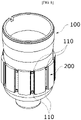
- FIG. 2 is a perspective view illustrating the shaft 100
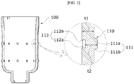
- FIG. 3 is a side cross-sectional view illustrating protrusions 110 of the shaft 100.
- the shaft 100 is a hollow member and may be formed through a pressing process.
- the shaft 100 includes the plurality of protrusions 110 in contact with the magnets 200.
- the plurality of protrusions 110 are disposed on the outer circumferential surface of the shaft 100.
- the plurality of protrusions 110 may be disposed to be spaced apart from each other in a circumferential direction O of the shaft 100.
- the plurality of protrusions 110 may be disposed to be spaced apart from each other in an axial direction X of the shaft 100.
- the protrusions 110 serve to arrange and fix the magnets 200 disposed on the outer circumferential surface of the shaft 100.
- the plurality of protrusions 110 include first faces 111 and second faces 112.
- the first faces 111 may protrude from the outer circumferential surface of the shaft 100.
- the second faces 112 may be concavely disposed in an inner circumferential surface of the shaft 100.
- the first faces 111 may include first-1 faces 111a and first-2 faces 111b.
- the first-1 faces 111a are portions protruding from the outer circumferential surface of the shaft 100.
- the first-2 faces 111b connect the outer circumferential surface of the shaft 100 and the first-1 faces 111a.
- the first-1 face 111a may include a flat surface, and the first-2 face 111b may include a curved surface in contact with the magnet 200.
- the curved surface of the first-2 face 111b is in line contact with a side surface of the magnet 200 to guide the magnet 200 to be smoothly inserted between the protrusions 110.
- a knurling structure may be applied to the first-2 face 111b to increase a fixing force between the shaft and the magnet.
- the second faces 112 may include second-1 faces 112a and second-2 faces 112b.
- the second-1 faces 112a are portions concavely formed in the inner circumferential surface of the shaft 100.
- the second-2 face 112b connects the inner circumferential surface of the shaft 100 and the second-1 face 112a.
- the second-1 face 112a may include a flat surface, and the second-2 face 112b may include a curved surface.
- the first face 111 and the second face 112 may be formed through an embossing process performed on an inner side of the hollow shaft 100.
- a distance t2 between the first face 111 and the second face 112 may be the same as a thickness t1 of the shaft 100 around the protrusion 110.
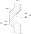
- FIG. 4 is a side cross-sectional view illustrating a modified example of the protrusion 110 of the shaft 100.
- a first-2 face 111b may be disposed to be inclined in a direction toward a first-1 face 111a.
- a second-2 face 112b may be disposed to be inclined in a direction toward a second-1 face 112a.
- a side cross-sectional shape of the protrusion 110 may be a substantially trapezoidal shape.
- a knurling structure may be applied to the first-2 face 111b to increase the fixing force between the shaft and the magnet.
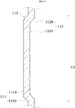
- FIG. 5 is a side cross-sectional view illustrating another modified example of the protrusion 110 of the shaft 100.
- the plurality of protrusions 110 may be disposed in the circumferential direction of the shaft 100, but one protrusion 110 may be disposed in the axial direction of the shaft 100.
- a first-1 face 111a and a second-1 face 112a may be longitudinally disposed in the axial direction.
- a knurling structure may be applied to the first-2 face 111b to increase the fixing force between the shaft and the magnet.
- the first face 111 and the second face 112 may be formed through a beading process performed on the inner side of the hollow shaft 100.
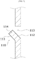
- FIGS. 6 and 7 are side cross-sectional views illustrating still other modified examples of the protrusion 110 of the shaft 100.
- the shaft 100 may include a first hole 113 passing through the inner side to an outer side of the shaft 100.
- the first hole 113 may be formed in a quadrangular shape.
- the protrusion 110 may extend from an edge of the first hole 113.
- a side surface of the protrusion 110 may include a flat surface 114 in contact with the magnet 200.
- the protrusion 110 may be provided as a plurality of protrusions disposed in the circumferential direction of the shaft 100.
- the protrusion 110 may be provided as a plurality of protrusions disposed in the axial direction of the shaft 100.
- a knurling structure may be applied to the flat surface 114, which is in contact with the magnet 200, of the side surface of the protrusion to increase the fixing force between the shaft 100 and the magnet 200.
- a first face 111 of the protrusion 110 may be disposed to be inclined downward.
- a second face 112 of the protrusion 110 may also be disposed to be inclined downward.
- a first face 111 of the protrusion 110 may be disposed to be inclined upward.
- a second face 112 of the protrusion 110 may also be disposed to be inclined upward.
- protrusions 110 having various shapes are illustrated, the present invention is not limited thereto, and the protrusion 110 may be changed to a protrusion 110 having one of various shapes formed through an embossing process performed on the inner side of the shaft 100.
- the magnet 200 disposed on the shaft 100 may be guided and fixed. Since the magnet 200 is directly guided and fixed to the shaft 100, there is an advantage of omitting a rotor core.
- the protrusion 110 may be implemented to have a small size, and the number of the protrusions 110 may be relatively greatly increased when compared to a general guide structure. Accordingly, there is an advantage of more precisely guiding a position of the magnet 200.
- FIG. 8 is a perspective view illustrating the shaft 100 on which the magnets 200 are disposed on the outer circumferential surface thereof.
- the plurality of magnets 200 are disposed on the outer circumferential surface of the shaft 100.
- the magnet 200 is disposed between the protrusions 110 in the circumferential direction of the shaft 100.
- the side surface of the protrusion 110 is in contact with the side surface of the magnet 200.
- FIG. 9 is a view illustrating a separation distance between the protrusions 110
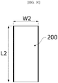
- FIG. 10 is a view illustrating a size of the magnet 200.
- a separation distance W1 between the protrusions 110 in the circumferential direction may be greater than or equal to a width W2 of the magnet 200. This is to allow the magnet 200 to be positioned between the protrusions 110 in the circumferential direction of the shaft 100.
- a separation distance L1 between the protrusions 110 in the axial direction may be smaller than or equal to a length L2 of the magnet 200. This is to guide the magnet 200 using at least two protrusions 110 disposed at the same column in the axial direction.
- a length L3 of the corresponding protrusion 110 may be greater than 1/2 times the length L2 of the magnet 200. This is a minimum length of the protrusion 110 so that the magnet 200 is guided and fixed by the protrusions 110 without being misaligned.
- FIG. 11 is a front view illustrating the shaft 100 in order for comparing a height of the protrusion 110 and a height of the magnet 200.
- a height H1 from the outer circumferential surface of the shaft 100 to an outer end of the protrusion 110 may be smaller than a height H2 of the magnet 200 in a radial direction of the shaft 100.
- a center of a width of the protrusion 110 in the circumferential direction of the shaft 100 may be a reference point of the height H1 of the protrusion 110.
- a center of a width of the magnet 200 in the circumferential direction of the shaft 100 may be a reference point of the height H2 of the magnet 200. This is in consideration of a position of the cover 400 which covers the magnet 200.
- the protrusion 110 is illustrated in FIG. 11 , even in the case of each of protrusions 120 having different shapes, a height from the outer circumferential surface of the shaft 100 to an outer end of the protrusion 120 may be smaller than the height H2 of the magnet 200.
- FIG. 12 is a view illustrating the shaft 100 on which the cover 400 is disposed in the overmolding manner
- FIG. 13 is a side cross-sectional view illustrating the shaft 100 illustrated in FIG. 12 .
- the cover 400 may be a molded member formed in the overmolding manner.
- the cover 400 includes grooves 410 in which the protrusions 110 are disposed. Since the protrusions 110 are disposed in the grooves 410, a coupling force between the cover 400 and the shaft 100 increases, and a coupling force between the cover 400 and the magnet 200 increases.
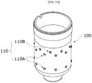
- FIG. 14 is a view illustrating protrusions 110 disposed at upper sides and lateral sides of the magnets 200.
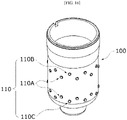
- the protrusions 110 include first-1 protrusions 110A disposed at the lateral sides of the magnets 200 and first-2 protrusions 110B disposed at the upper sides of the magnets 200. Since the first-2 protrusion 110B is disposed at the upper side of the magnet 200 to be in contact with an upper end of the magnet 200, the magnet 200 may be prevented from escaping upward from a regular position.
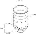
- FIG. 15 is a view illustrating protrusions 110 disposed at lower sides and the lateral sides of the magnets 200.
- the protrusions 110 may include first-1 protrusions 110A disposed at the lateral sides of the magnets 200 and first-3 protrusions 110C disposed at the lower sides of the magnets 200. Since the first-3 protrusion 110C is disposed at the lower side of the magnet 200 to be in contact with the magnet 200, the magnet 200 may be prevented from escaping downward from the regular position.
- FIG. 16 is a view illustrating protrusions 110 disposed at the upper sides and the lower sides of the magnets 200.
- the protrusions 110 may include first-1 protrusions 110A disposed at the lateral sides of the magnets 200, first-2 protrusions 110B disposed at the upper sides of the magnets 200, and first-3 protrusions 110C disposed at the lower sides of the magnets 200. Since the first-2 protrusion 110B is in contact with the upper end of the magnet 200, the magnet 200 is prevented from escaping upward from the regular position, and since the first-3 protrusion 110C is in contact with the lower end of the magnet 200, the magnet 200 is prevented from escaping downward from the regular position.
- a protrusion 120 which has a form different from the form described above, illustrated in each of FIGS. 17 to 19 may also include at least one of the first-1 protrusion disposed at the lateral side of the magnet 200, the first-2 protrusion disposed at the upper side of the magnet 200, and the first-3 protrusion 110C disposed at the lower side of the magnet 200.
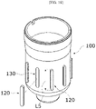
- FIG. 17 is a view illustrating the shaft 100 including the protrusions 120 and second holes 130.
- the shaft 100 may include the second holes 130 passing through the inner side to the outer side of the shaft 100.
- the plurality of second holes 130 may be disposed in the circumferential direction of the shaft 100.
- the plurality of second holes 130 may be disposed in the axial direction of the shaft 100.
- the plurality of second holes 130 may be formed through a punching process.
- the protrusions 120 may be disposed in the plurality of second holes 130.
- the protrusion 120 is disposed so that at least a part of the protrusion 120 protrudes from the outer circumferential surface of the shaft 100 in a state in which the protrusion 120 is inserted into the second hole 130.
- the protrusion 120 may be formed of a plastic resin.
- the protrusion 120 is in contact with the magnet 200.
- a thread capable of increasing a coupling force between the protrusion 120 and the shaft 100 may be formed in an area of a side surface, with which the shaft 100 is in contact, of the protrusion 120.
- a knurling structure for increasing the fixing force between the magnet 200 and the shaft 100 may be applied to the portion, which is not in contact with the shaft 100, of the side surface of the protrusion 120.
- FIG. 18 is a perspective view illustrating the shaft 100 including protrusions 120 which are a modified example thereof.
- one second hole 130 having a long hole shape may be disposed in the axial direction of the shaft 100.
- the plurality of protrusions 120 may also be disposed in the circumferential direction to correspond thereto, one protrusion 120 may be disposed in the axial direction of the shaft 100.
- a knurling structure for increasing the fixing force between the magnet 200 and the shaft 100 may be applied to a portion, which is not in contact with the shaft 100, of the side surface of the protrusion 120.
- a separation distance W3 between the protrusions 120 in the circumferential direction may be greater than or equal to the width W2 of the magnet 200. This is to allow the magnet 200 to be positioned between the protrusions 120 in the circumferential direction of the shaft 100.
- a separation distance L4 between the protrusions 120 in the axial direction may be smaller than or equal to the length L2 of the magnet 200. This is to allow at least two protrusions 120, which are disposed at the same column in the axial direction, to guide the magnet 200.
- a length L5 of the protrusion 110 may be greater than 1/2 times the length L2 of the magnet 200. This is a minimum length of the protrusion 120 so that the magnet 200 may be guided and fixed by the protrusions 120 without being misaligned.
- FIG. 19 is a side cross-sectional view illustrating the shaft 100 on which the cover 400 is disposed in an overmolding manner.
- the cover 400 includes grooves 420 in which the protrusions 120 are disposed. Since the protrusion 120 is disposed in the groove 420, a coupling force between the cover 400 and the shaft 100 increases, and a coupling force between the cover 400 and the magnet 200 increases at the same time.
- FIG. 20 is a view illustrating the shaft on which the cover 400 is disposed
- FIG. 21 is a view illustrating a state in which the cover 400 is surrounding the magnets 200 disposed on the outer circumferential surface of the shaft 100.
- the cover 400 may be an adhesive member which surrounds the magnet 200 to fix the magnet 200 to the shaft 100.
- the cover 400 may be a member in which a matrix is impregnated in reinforced fiber.
- the cover 400 is a member in a semi-cured state and serves as an adhesive sheet which fixes the magnet 200 to the shaft 100.
- the reinforced fiber may be mainly carbon fiber, glass fiber, aramid fiber, or the like, and the matrix may be an epoxy resin, a polyester resin, or a thermoplastic resin.
- the carbon fiber has features of high tensile strength and high tensile modulus as mechanical properties and high heat resistance and high fire resistance as thermal properties.
- the glass fiber has features of high tensile strength and high tensile modulus as mechanical properties and a low coefficient of linear expansion as a thermal property. Both of the carbon fiber and the glass fiber have a high electrical insulation property.
- the cover 400 In a state in which a part of the cover 400 is in contact with the shaft 100 and the magnet 200, when the shaft 100 rotates, the cover 400 may be wound around the shaft 100 in the form of naturally surrounding the magnet 200, and thus there is an advantage of a simple and rapid process.
- the cover 400 may be divided into a first part 410, a second part 420, and a third part 430 in the axial direction.
- the second part 420 extends from one side of the first part 410.
- the third part 430 extends from the other side of the first part 410.
- the first part 410 is a part which covers the magnet 200, and the second part 420 and the third part 430 are parts in contact with the shaft 100.
- FIG. 22 is a side cross-sectional view illustrating the shaft 100, the magnet 200, and cover 400.
- an inner surface of the magnet 200 is in contact with an outer surface of the shaft 100.
- an outer surface of the magnet 200 is in contact with an inner surface 401 of the first part 410.
- a part of an inner surface 402 of the second part 420 is in contact with the outer surface of the shaft 100, and the remaining part of the inner surface 402 of the second part 420 is disposed to be spaced apart from the outer surface of the shaft 100.
- a space S1 is formed between the outer surface of the shaft 100, a surface of one end 203 of the magnet 200, and the inner surface 402 of the second part 420.
- a part of an inner surface 403 of the third part 430 is in contact with the outer surface of the shaft 100, and the remaining part of the inner surface 403 of the third part 430 is disposed to be spaced apart from the outer surface of the shaft 100.
- a space S2 is formed between the outer surface of the shaft 100, a surface of the other end 204 of the magnet 200, and the inner surface 403 of the third part 430.
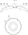
- FIG. 23 is a plan cross-sectional view illustrating the shaft 100, the magnet 200, and the cover 400.
- the cover 400 may include a plurality of first regions A1.
- the plurality of first regions A1 may be disposed to be spaced apart from each other in the circumferential direction around a center of the shaft.
- a distance R1 from the outer surface of the shaft 100 to the first region A1 in the radial distance is smaller than a shortest distance R2 from the outer surface of the shaft 100 to the outer surface of the magnet 200 in the radial direction.
- a side end of the outer surface of the magnet 200 in the circumferential direction may be a reference point of the shortest distance R2 from the outer surface of the shaft 100 to the outer surface of the magnet 200 when a bread shape of the outer surface of the magnet 200 is considered.
- the first region A1 is disposed between a first unit magnet 200A and a second unit magnet 200B in the circumferential direction.
- the first region A1 is longitudinally disposed in the axial direction.
- a layout of the magnet 200 may be checked visually or checked through an image in a state in which the cover 400 surrounds the magnet 200. Accordingly, an operator may easily check whether there is a problem in the layout of the magnet 200.
- FIG. 24 is a plan cross-sectional view illustrating the shaft 100 and the magnet 200 which show a second region A2 and a third region A3 of the cover.
- the cover 400 may be wound around the shaft 100 to constitute a multilayer.
- a region in which the cover 400 constitutes the multilayer in the radial direction is referred to as the second region A2
- a region having a thickness t2 different from a thickness t1 of one region in the radial direction from the center of the shaft is referred to as a third region A3.
- the cover 400 may include a first layer 400A and a second layer 400B stacked on the first layer 400A in the second region A2.
- first layer 400A and the second layer 400B are illustrated, the present invention is not limited thereto, and more layers, such as a third layer, a four layer, and the like, may be formed.
- the second region A2 may be a region in which three or more layers are formed.
- FIG. 24 although it is illustrated that a position of the second region A2 and a position of the third region A3 are the same, the present invention is not limited thereto, and the position of the second region A2 and the position of the third region A3 may be also be different.
- An outer surface of the cover 400 may include a stepped region A4.
- FIG. 25 is a view illustrating one side edges E1 and E2 of the cover 400 in the second region A2.
- one side edge E2 of any one layer may be disposed to be inclined with respect to one side edge E1 of another layer.
- the other edge E4 of any one layer may be disposed to be inclined with respect to the other side edge E3 of another layer. This may be a feature which is naturally formed in a process in which an end of the cover 400 is finished and attached after the cover 400 is wound around the shaft 100.
- FIG. 26 is a perspective view illustrating the shaft including the protrusions
- FIG. 27 is a plan cross-sectional view illustrating the shaft 100 including the protrusion and the magnet 200.
- the shaft 100 includes the plurality of protrusions 110 in contact with the magnet 200.
- the plurality of protrusions 110 are disposed on the outer circumferential surface of the shaft 100.
- the plurality of protrusions 110 may be disposed to be spaced apart from each other in the circumferential direction of the shaft 100.
- the plurality of protrusions 110 may be disposed to be spaced apart from each other in the axial direction X of the shaft 100.
- the protrusions 110 serve to arrange and fix the magnet 200 disposed on the outer circumferential surface of the shaft 100.
- the protrusion may be formed through an embossing process performed on the inner side of the hollow shaft 100.
- the protrusions 110 serve to fix the magnet 200 to prevent the magnet from being misaligned while the cover 400 surrounds the magnet 200.
- the protrusion 110 may be disposed to be spaced apart from the cover 400.
Landscapes
- Engineering & Computer Science (AREA)
- Power Engineering (AREA)
- Permanent Field Magnets Of Synchronous Machinery (AREA)
- Iron Core Of Rotating Electric Machines (AREA)
Abstract
Description
- The present invention relates to a motor.
- Motors are apparatuses configured to convert electrical energy to mechanical energy to obtain rotational forces and are widely used for vehicles, home appliances, industrial machines, and the like.
- Particularly, an electronic power steering (EPS) system in which the motor is used secures turning stability and provides a rapid restoring force by driving the motor according to traveling conditions using an electronic control unit (ECU). Accordingly, a driver of a vehicle can drive safely.
- A motor includes a shaft and a stator. The shaft may have a hollow shape. Magnets may be attached to an outer circumferential surface of the shaft. In this case, the hollow shaft has a problem of difficulty in aligning positions of the magnets. This is because it is difficult to form guides for aligning the magnets due to a process of machining the hollow shaft. When there are no guides, which guide the magnets, on the shaft, and when the magnets are overmolded, a problem of misalignment of the magnet may occur. In addition, when the magnets are surrounded by a can or adhesive member, there is a risk of movement of the magnet.
- Meanwhile, an adhesive is used to fix the magnets to the shaft. When the adhesive is used, there is a problem in that a long time is required for curing. In addition, when the magnets are overmolded, a problem of misalignment of the magnet may occur, and there is a problem in that it is difficult to check the misalignment. In addition, in the case of overmolding, since a thickness is large, there is a difficulty in securing a gap with respect to the stator.
- The present invention is directed to providing a motor allowing a magnet disposed on an outer circumferential surface of a hollow shaft to be aligned and fixed.
- In addition, the present invention is directed to providing a motor in which a gap between a magnet and a stator is reduced, of which a process is simplified, and in which a position of the magnet is checked.
- One aspect of the present invention provides a motor including a stator, a shaft having a hollow and disposed inside the stator, and a magnet disposed on an outer circumferential surface of the shaft, wherein the shaft includes a plurality of protrusions in contact with the magnet, and the plurality of protrusions include first faces protruding from the outer circumferential surface of the shaft and second faces concavely disposed in an inner circumferential surface of the shaft.
- Another aspect of the present invention provides a motor including a stator, a shaft having a hollow and disposed inside the stator, and a magnet disposed on an outer circumferential surface of the shaft, wherein the shaft includes a plurality of second holes passing through an inner side to an outer side of the shaft and a plurality of protrusions which are disposed in the plurality of second holes and of which at least parts protrude from the outer circumferential surface of the shaft and are in contact with the magnet.
- The plurality of protrusions may be disposed to be spaced apart from each other in a circumferential direction of the shaft, and a separation distance between the plurality of protrusions in the circumferential direction may be greater than or equal to a width of the magnet.
- The plurality of protrusions may be disposed to be spaced apart from each other in an axial direction of the shaft, and a separation distance between the protrusions in the axial direction may be smaller than or equal to a length of the magnet.
- One protrusion of the plurality of protrusions may be disposed in an axial direction of the shaft, and a length of the one protrusion in the axial direction may be greater than 1/2 times a length of the magnet.
- Each of the first face and the second face may include at least one flat surface.
- The first face may include a curved surface in contact with the magnet.
- A height from the outer circumferential surface of the shaft to an outer end of the protrusion may be smaller than a height of the magnet in a radial direction of the shaft.
- The shaft may include a first hole which passes from in inner side to an outer side of the shaft, and the protrusion may extend from an edge of the first hole.
- The motor may include a cover disposed outside the magnet, and the cover may include a groove in which the protrusion is disposed.
- Threads may be disposed at a side surface of the protrusion and the second hole. A knurling structure may be disposed on the protrusion.
- Still another aspect of the present invention provides a motor including a stator, a shaft disposed inside the stator, a magnet coupled to the shaft, and a cover disposed outside the magnet, wherein the cover includes a first part and a second part extending from one side of the first part, an inner surface of the magnet is in contact with an outer surface of the shaft, an outer surface of the magnet is in contact with an inner surface of the first part, a part of an inner surface of the second part is in contact with the outer surface of the shaft, and the remaining part of the inner surface of the second part is disposed to be spaced apart from the outer surface of the shaft so that a space is disposed between the outer surface of the shaft and the inner surface of the second part.
- The cover may include a third part extending from the other side of the first part, a part of an inner surface of the third part may be in contact with the outer surface of the shaft, and the remaining part of the inner surface of the third part may be disposed to be spaced apart from the outer surface of the shaft so that a space is disposed between the outer surface of the shaft and a surface of the other end of the magnet.
- The cover may include a plurality of first regions disposed to be spaced apart from each other in a circumferential direction around a center of the shaft, and a distance from the outer surface of the shaft to the first region in a radial direction may be smaller than a shortest distance from the outer surface of the shaft to the outer surface of the magnet in the radial direction.
- The magnet may include a first unit magnet and a second unit magnet, the first region may be disposed between the first unit magnet and the second unit magnet, and the first region may be disposed in an axial direction.
- The cover may include a second region constituting a multilayer in a radial direction from a center of the shaft.
- The cover may include a first layer and a second layer stacked on the first layer in the second region, and one side edge of the second layer may be disposed to be inclined with respect to one side edge of the first layer.
- The cover may include a third region having a different thickness in the radial direction from a center of the shaft.
- An outer surface of the cover may include a stop region.
- The cover may be a member in which epoxy is impregnated in fiber.
- The shaft may include a protrusion in contact with the magnet, and the protrusion may be disposed to be spaced apart from the cover.
- According to the embodiment, a useful effect of easily aligning a magnet disposed on an outer circumferential surface of a hollow shaft is provided.
- According to the embodiment, a useful effect of preventing movement of the magnet when the magnet is surrounded in an overmolding manner or by a can is provided.
- According to the embodiment, since a size of each protrusion can be formed to be small, the number of the protrusions can be increased, and thus there is an advantage of more precisely guiding a position of the magnet.
- According to the embodiment, there is an advantage of easily forming the protrusion through an embossing or punching process.
- According to the embodiment, there is an advantage of preventing the magnet from escaping in a process using a knurling structure formed on a side surface of the protrusion.
- According to the embodiment, there is an advantage of improving the performance of a motor by minimizing a thickness of a cover to significantly reduce a gap between the magnet and the stator.
- According to the embodiment, since the position of the magnet can be checked from the outside of the cover, there is an advantage of easily identifying a defect of the magnet.
- According to the embodiment, since an adhesive is not used when the magnet is fixed to the shaft, there is an advantage of reducing a process time.
-
-
FIG. 1 is a view illustrating a motor according to an embodiment. -
FIG. 2 is a perspective view illustrating a shaft. -
FIG. 3 is a side cross-sectional view illustrating protrusions of the shaft. -
FIG. 4 is a side cross-sectional view illustrating a modified example of the protrusion of the shaft. -
FIG. 5 is a side cross-sectional view illustrating another modified example of the protrusion of the shaft. -
FIGS. 6 and7 are side cross-sectional views illustrating still other modified examples of the protrusion of the shaft. -
FIG. 8 is a perspective view illustrating the shaft on which magnets are disposed on an outer circumferential surface thereof. -
FIG. 9 is a view illustrating a separation distance between the protrusions. -
FIG. 10 is a view illustrating a size of the magnet. -
FIG. 11 is a front view illustrating the shaft in order for comparing a height of the protrusion and a height of the magnet. -
FIG. 12 is a view illustrating the shaft on which a cover is disposed in an overmolding manner. -
FIG. 13 is a side cross-sectional view illustrating the shaft illustrated inFIG. 12 . -
FIG. 14 is a view illustrating protrusions disposed at upper sides of the magnets. -
FIG. 15 is a view illustrating protrusions disposed at lower sides of the magnets. -
FIG. 16 is a view illustrating protrusions disposed at upper sides and lower sides of the magnets. -
FIG. 17 is a view illustrating the shaft including protrusions and second holes. -
FIG. 18 is a perspective view illustrating the shaft including protrusions which are a modified example thereof. -
FIG. 19 is a side cross-sectional view illustrating the shaft on which a cover is disposed in an overmolding manner. -
FIG. 20 is a view illustrating the shaft on which the cover is disposed. -
FIG. 21 is a view illustrating a state in which the cover is surrounding the magnets disposed on the outer circumferential surface of the shaft. -
FIG. 22 is a side cross-sectional view illustrating the shaft, the magnet, and the cover. -
FIG. 23 is a plan cross-sectional view illustrating the shaft, the magnet, and the cover. -
FIG. 24 is a plan cross-sectional view illustrating the shaft and the magnet which show a second region and a third region of the cover. -
FIG. 25 is a view illustrating one side edge of the cover in the second region. -
FIG. 26 is a perspective view illustrating the shaft including the protrusions. -
FIG. 27 is a plan cross-sectional view illustrating the shaft including the protrusion and the magnet. - Hereinafter, exemplary embodiments of the present invention will be described in detail with reference to the accompanying drawings.
- However, the technical spirit of the present invention is not limited to some embodiments which will be described and may be realized using various other embodiments, and at least one component of the embodiments may be selectively coupled, substituted, and used to realize the technical spirit within the range of the technical spirit.
- In addition, unless clearly and specifically defined otherwise by context, all terms (including technical and scientific terms) used herein can be interpreted as having customary meanings to those skilled in the art, and meanings of generally used terms, such as those defined in commonly used dictionaries, will be interpreted by considering contextual meanings of the related technology.
- In addition, the terms used in the embodiments of the present invention are considered in a descriptive sense and not for limiting the present invention.
- In the present specification, unless clearly indicated otherwise by the context, singular forms include the plural forms thereof, and in a case in which "at least one (or one or more) among A, B, and C" is described, this may include at least one combination among all possible combinations thereof.
- In addition, in descriptions of components of the present invention, terms such as "first," "second," "A," "B," "(a)," and "(b)" can be used.
- The terms are only to distinguish one element from another element, and an essence, order, and the like of the element are not limited by the terms.
- In addition, it should be understood that, when an element is referred to as being "connected or coupled" to another element, such a description may include both of a case in which the element is directly connected or coupled to another element and a case in which the element is connected or coupled to another element with still another element disposed therebetween.
- In addition, in a case in which any one element is described as being formed or disposed "on or under" another element, such a description includes both a case in which the two elements are formed or disposed in direct contact with each other and a case in which one or more other elements are interposed between the two elements. In addition, when one element is described as being disposed "on or under" another element, such a description may include a case in which the one element is disposed at an upper side or a lower side with respect to another element.
-
FIG. 1 is a view illustrating a motor according to the embodiment. - Referring to
FIG. 1 , the motor according to the embodiment may include ashaft 100, amagnet 200, astator 300, acover 400, ahousing 500, and abusbar 600. Hereinafter, the term "inside" denotes a direction toward theshaft 100 in a radial direction of the motor, and the term "outside" denotes a direction opposite to "inside." - The
shaft 100 may be a hollow member of which one side is open. Both ends of theshaft 100 may be rotatably supported by bearings in a axial direction. Portions, of which outer diameters are different, of theshaft 100 may be divided and disposed in the axial direction. - The
magnet 200 is disposed on an outer circumferential surface of theshaft 100. Themagnet 200 is rotated in conjunction with rotation of theshaft 100. Themagnet 200 may be provided as a plurality of magnets. - The
stator 300 is disposed outside theshaft 100 and themagnet 200. Thestator 300 may include astator core 310,insulators 320 installed on thestator core 310, and coils 330 wound around theinsulators 320. Thecoil 330 generates a magnetic field. Thestator core 310 may be one member or a combination of a plurality of divided cores. In addition, thestator core 310 may be formed in a form in which a plurality of thin steel plates are stacked, but the present invention is not necessarily limited thereto. For example, thestator core 310 may also be formed as one single part. - The
cover 400 fixes themagnet 200 to theshaft 100. Thecover 400 surrounds some regions of themagnet 200 and some regions of theshaft 100. Thecover 400 may be a molded member formed in an overmolding manner or a can member or adhesive member surrounding themagnet 200. - The
housing 500 may be disposed outside thestator 300. Thehousing 500 may be a cylindrical member of which an upper portion is open. Thehousing 500 accommodates theshaft 100, themagnet 200, thestator 300, and thecover 400 thereinside. In addition, thehousing 500 may accommodate the bearing which supports theshaft 100. - The
busbar 600 is disposed on thestator 300. Thebusbar 600 connects thecoils 330 wound around the cores of thestator 300. -
FIG. 2 is a perspective view illustrating theshaft 100, andFIG. 3 is a side cross-sectionalview illustrating protrusions 110 of theshaft 100. - The
shaft 100 is a hollow member and may be formed through a pressing process. - Referring to
FIGS. 2 and3 , theshaft 100 includes the plurality ofprotrusions 110 in contact with themagnets 200. The plurality ofprotrusions 110 are disposed on the outer circumferential surface of theshaft 100. The plurality ofprotrusions 110 may be disposed to be spaced apart from each other in a circumferential direction O of theshaft 100. In addition, the plurality ofprotrusions 110 may be disposed to be spaced apart from each other in an axial direction X of theshaft 100. Theprotrusions 110 serve to arrange and fix themagnets 200 disposed on the outer circumferential surface of theshaft 100. - The plurality of
protrusions 110 include first faces 111 and second faces 112. The first faces 111 may protrude from the outer circumferential surface of theshaft 100. The second faces 112 may be concavely disposed in an inner circumferential surface of theshaft 100. - The first faces 111 may include first-1
faces 111a and first-2faces 111b. The first-1faces 111a are portions protruding from the outer circumferential surface of theshaft 100. The first-2faces 111b connect the outer circumferential surface of theshaft 100 and the first-1faces 111a. The first-1face 111a may include a flat surface, and the first-2face 111b may include a curved surface in contact with themagnet 200. The curved surface of the first-2face 111b is in line contact with a side surface of themagnet 200 to guide themagnet 200 to be smoothly inserted between theprotrusions 110. In addition, a knurling structure may be applied to the first-2face 111b to increase a fixing force between the shaft and the magnet. - The second faces 112 may include second-1
faces 112a and second-2faces 112b. The second-1faces 112a are portions concavely formed in the inner circumferential surface of theshaft 100. The second-2face 112b connects the inner circumferential surface of theshaft 100 and the second-1face 112a. The second-1face 112a may include a flat surface, and the second-2face 112b may include a curved surface. - The
first face 111 and thesecond face 112 may be formed through an embossing process performed on an inner side of thehollow shaft 100. A distance t2 between thefirst face 111 and thesecond face 112 may be the same as a thickness t1 of theshaft 100 around theprotrusion 110. -
FIG. 4 is a side cross-sectional view illustrating a modified example of theprotrusion 110 of theshaft 100. - Referring to
FIG. 4 , in the modified example of theprotrusion 110, a first-2face 111b may be disposed to be inclined in a direction toward a first-1face 111a. In addition, a second-2face 112b may be disposed to be inclined in a direction toward a second-1face 112a. A side cross-sectional shape of theprotrusion 110 may be a substantially trapezoidal shape. In addition, a knurling structure may be applied to the first-2face 111b to increase the fixing force between the shaft and the magnet. -
FIG. 5 is a side cross-sectional view illustrating another modified example of theprotrusion 110 of theshaft 100. - Referring to
FIG. 5 , the plurality ofprotrusions 110 may be disposed in the circumferential direction of theshaft 100, but oneprotrusion 110 may be disposed in the axial direction of theshaft 100. In oneprotrusion 110, a first-1face 111a and a second-1face 112a may be longitudinally disposed in the axial direction. In addition, a knurling structure may be applied to the first-2face 111b to increase the fixing force between the shaft and the magnet. Thefirst face 111 and thesecond face 112 may be formed through a beading process performed on the inner side of thehollow shaft 100. -
FIGS. 6 and7 are side cross-sectional views illustrating still other modified examples of theprotrusion 110 of theshaft 100. - Referring to
FIGS. 6 and7 , theshaft 100 may include afirst hole 113 passing through the inner side to an outer side of theshaft 100. Thefirst hole 113 may be formed in a quadrangular shape. Theprotrusion 110 may extend from an edge of thefirst hole 113. A side surface of theprotrusion 110 may include aflat surface 114 in contact with themagnet 200. Theprotrusion 110 may be provided as a plurality of protrusions disposed in the circumferential direction of theshaft 100. In addition, theprotrusion 110 may be provided as a plurality of protrusions disposed in the axial direction of theshaft 100. In addition, a knurling structure may be applied to theflat surface 114, which is in contact with themagnet 200, of the side surface of the protrusion to increase the fixing force between theshaft 100 and themagnet 200. - For example, as illustrated in
FIG. 6 , afirst face 111 of theprotrusion 110 may be disposed to be inclined downward. In addition, asecond face 112 of theprotrusion 110 may also be disposed to be inclined downward. - Alternatively, as illustrated in
FIG. 7 , afirst face 111 of theprotrusion 110 may be disposed to be inclined upward. In addition, asecond face 112 of theprotrusion 110 may also be disposed to be inclined upward. - Although the
protrusions 110 having various shapes are illustrated, the present invention is not limited thereto, and theprotrusion 110 may be changed to aprotrusion 110 having one of various shapes formed through an embossing process performed on the inner side of theshaft 100. - By using the
protrusion 110, themagnet 200 disposed on theshaft 100 may be guided and fixed. Since themagnet 200 is directly guided and fixed to theshaft 100, there is an advantage of omitting a rotor core. - In addition, the
protrusion 110 may be implemented to have a small size, and the number of theprotrusions 110 may be relatively greatly increased when compared to a general guide structure. Accordingly, there is an advantage of more precisely guiding a position of themagnet 200. - In addition, there is an advantage of easily forming the
protrusion 110 through the embossing process. -
FIG. 8 is a perspective view illustrating theshaft 100 on which themagnets 200 are disposed on the outer circumferential surface thereof. - Referring to
FIG. 8 , the plurality ofmagnets 200 are disposed on the outer circumferential surface of theshaft 100. Themagnet 200 is disposed between theprotrusions 110 in the circumferential direction of theshaft 100. The side surface of theprotrusion 110 is in contact with the side surface of themagnet 200. -
FIG. 9 is a view illustrating a separation distance between theprotrusions 110, andFIG. 10 is a view illustrating a size of themagnet 200. - Referring to
FIGS. 9 and10 , a separation distance W1 between theprotrusions 110 in the circumferential direction may be greater than or equal to a width W2 of themagnet 200. This is to allow themagnet 200 to be positioned between theprotrusions 110 in the circumferential direction of theshaft 100. - In addition, referring to
FIGS. 9 and10 , a separation distance L1 between theprotrusions 110 in the axial direction may be smaller than or equal to a length L2 of themagnet 200. This is to guide themagnet 200 using at least twoprotrusions 110 disposed at the same column in the axial direction. - Meanwhile, as illustrated in
FIG. 5 , when oneprotrusion 110 is disposed in the axial direction of theshaft 100, a length L3 of thecorresponding protrusion 110 may be greater than 1/2 times the length L2 of themagnet 200. This is a minimum length of theprotrusion 110 so that themagnet 200 is guided and fixed by theprotrusions 110 without being misaligned. -
FIG. 11 is a front view illustrating theshaft 100 in order for comparing a height of theprotrusion 110 and a height of themagnet 200. - Referring to
FIG. 11 , a height H1 from the outer circumferential surface of theshaft 100 to an outer end of theprotrusion 110 may be smaller than a height H2 of themagnet 200 in a radial direction of theshaft 100. A center of a width of theprotrusion 110 in the circumferential direction of theshaft 100 may be a reference point of the height H1 of theprotrusion 110. In addition, a center of a width of themagnet 200 in the circumferential direction of theshaft 100 may be a reference point of the height H2 of themagnet 200. This is in consideration of a position of thecover 400 which covers themagnet 200. Although theprotrusion 110 is illustrated inFIG. 11 , even in the case of each ofprotrusions 120 having different shapes, a height from the outer circumferential surface of theshaft 100 to an outer end of theprotrusion 120 may be smaller than the height H2 of themagnet 200. -
FIG. 12 is a view illustrating theshaft 100 on which thecover 400 is disposed in the overmolding manner, andFIG. 13 is a side cross-sectional view illustrating theshaft 100 illustrated inFIG. 12 . - Referring to
FIGS. 12 and13 , thecover 400 may be a molded member formed in the overmolding manner. Thecover 400 includesgrooves 410 in which theprotrusions 110 are disposed. Since theprotrusions 110 are disposed in thegrooves 410, a coupling force between thecover 400 and theshaft 100 increases, and a coupling force between thecover 400 and themagnet 200 increases. -
FIG. 14 is aview illustrating protrusions 110 disposed at upper sides and lateral sides of themagnets 200. - Referring to
FIG. 14 , theprotrusions 110 include first-1protrusions 110A disposed at the lateral sides of themagnets 200 and first-2protrusions 110B disposed at the upper sides of themagnets 200. Since the first-2protrusion 110B is disposed at the upper side of themagnet 200 to be in contact with an upper end of themagnet 200, themagnet 200 may be prevented from escaping upward from a regular position. -
FIG. 15 is aview illustrating protrusions 110 disposed at lower sides and the lateral sides of themagnets 200. - Referring to
FIG. 15 , theprotrusions 110 may include first-1protrusions 110A disposed at the lateral sides of themagnets 200 and first-3protrusions 110C disposed at the lower sides of themagnets 200. Since the first-3protrusion 110C is disposed at the lower side of themagnet 200 to be in contact with themagnet 200, themagnet 200 may be prevented from escaping downward from the regular position. -
FIG. 16 is aview illustrating protrusions 110 disposed at the upper sides and the lower sides of themagnets 200. - Referring to
FIG. 16 , theprotrusions 110 may include first-1protrusions 110A disposed at the lateral sides of themagnets 200, first-2protrusions 110B disposed at the upper sides of themagnets 200, and first-3protrusions 110C disposed at the lower sides of themagnets 200. Since the first-2protrusion 110B is in contact with the upper end of themagnet 200, themagnet 200 is prevented from escaping upward from the regular position, and since the first-3protrusion 110C is in contact with the lower end of themagnet 200, themagnet 200 is prevented from escaping downward from the regular position. - Although the
protrusion 110 has been illustrated as described above, aprotrusion 120, which has a form different from the form described above, illustrated in each ofFIGS. 17 to 19 may also include at least one of the first-1 protrusion disposed at the lateral side of themagnet 200, the first-2 protrusion disposed at the upper side of themagnet 200, and the first-3protrusion 110C disposed at the lower side of themagnet 200. -
FIG. 17 is a view illustrating theshaft 100 including theprotrusions 120 andsecond holes 130. - Referring to
FIG. 17 , theshaft 100 may include thesecond holes 130 passing through the inner side to the outer side of theshaft 100. The plurality ofsecond holes 130 may be disposed in the circumferential direction of theshaft 100. In addition, the plurality ofsecond holes 130 may be disposed in the axial direction of theshaft 100. The plurality ofsecond holes 130 may be formed through a punching process. - The
protrusions 120 may be disposed in the plurality ofsecond holes 130. Theprotrusion 120 is disposed so that at least a part of theprotrusion 120 protrudes from the outer circumferential surface of theshaft 100 in a state in which theprotrusion 120 is inserted into thesecond hole 130. Theprotrusion 120 may be formed of a plastic resin. Theprotrusion 120 is in contact with themagnet 200. A thread capable of increasing a coupling force between theprotrusion 120 and theshaft 100 may be formed in an area of a side surface, with which theshaft 100 is in contact, of theprotrusion 120. A knurling structure for increasing the fixing force between themagnet 200 and theshaft 100 may be applied to the portion, which is not in contact with theshaft 100, of the side surface of theprotrusion 120. -
FIG. 18 is a perspective view illustrating theshaft 100 includingprotrusions 120 which are a modified example thereof. - Referring to
FIG. 18 , although a plurality ofsecond holes 130 may be disposed in the circumferential direction, onesecond hole 130 having a long hole shape may be disposed in the axial direction of theshaft 100. In addition, although the plurality ofprotrusions 120 may also be disposed in the circumferential direction to correspond thereto, oneprotrusion 120 may be disposed in the axial direction of theshaft 100. A knurling structure for increasing the fixing force between themagnet 200 and theshaft 100 may be applied to a portion, which is not in contact with theshaft 100, of the side surface of theprotrusion 120. - Referring to
FIG. 17 , a separation distance W3 between theprotrusions 120 in the circumferential direction may be greater than or equal to the width W2 of themagnet 200. This is to allow themagnet 200 to be positioned between theprotrusions 120 in the circumferential direction of theshaft 100. - In addition, a separation distance L4 between the
protrusions 120 in the axial direction may be smaller than or equal to the length L2 of themagnet 200. This is to allow at least twoprotrusions 120, which are disposed at the same column in the axial direction, to guide themagnet 200. - Referring to
FIG. 18 , when oneprotrusion 120 is disposed in the axial direction, a length L5 of theprotrusion 110 may be greater than 1/2 times the length L2 of themagnet 200. This is a minimum length of theprotrusion 120 so that themagnet 200 may be guided and fixed by theprotrusions 120 without being misaligned. -
FIG. 19 is a side cross-sectional view illustrating theshaft 100 on which thecover 400 is disposed in an overmolding manner. - Referring to
FIG. 19 , thecover 400 includesgrooves 420 in which theprotrusions 120 are disposed. Since theprotrusion 120 is disposed in thegroove 420, a coupling force between thecover 400 and theshaft 100 increases, and a coupling force between thecover 400 and themagnet 200 increases at the same time. -
FIG. 20 is a view illustrating the shaft on which thecover 400 is disposed, andFIG. 21 is a view illustrating a state in which thecover 400 is surrounding themagnets 200 disposed on the outer circumferential surface of theshaft 100. - Referring to
FIGS. 20 and21 , thecover 400 may be an adhesive member which surrounds themagnet 200 to fix themagnet 200 to theshaft 100. For example, thecover 400 may be a member in which a matrix is impregnated in reinforced fiber. - The
cover 400 is a member in a semi-cured state and serves as an adhesive sheet which fixes themagnet 200 to theshaft 100. The reinforced fiber may be mainly carbon fiber, glass fiber, aramid fiber, or the like, and the matrix may be an epoxy resin, a polyester resin, or a thermoplastic resin. The carbon fiber has features of high tensile strength and high tensile modulus as mechanical properties and high heat resistance and high fire resistance as thermal properties. The glass fiber has features of high tensile strength and high tensile modulus as mechanical properties and a low coefficient of linear expansion as a thermal property. Both of the carbon fiber and the glass fiber have a high electrical insulation property. - In a state in which a part of the
cover 400 is in contact with theshaft 100 and themagnet 200, when theshaft 100 rotates, thecover 400 may be wound around theshaft 100 in the form of naturally surrounding themagnet 200, and thus there is an advantage of a simple and rapid process. - The
cover 400 may be divided into afirst part 410, asecond part 420, and athird part 430 in the axial direction. Thesecond part 420 extends from one side of thefirst part 410. Thethird part 430 extends from the other side of thefirst part 410. - The
first part 410 is a part which covers themagnet 200, and thesecond part 420 and thethird part 430 are parts in contact with theshaft 100. -
FIG. 22 is a side cross-sectional view illustrating theshaft 100, themagnet 200, and cover 400. - Referring to
FIG. 22 , an inner surface of themagnet 200 is in contact with an outer surface of theshaft 100. In addition, an outer surface of themagnet 200 is in contact with aninner surface 401 of thefirst part 410. A part of aninner surface 402 of thesecond part 420 is in contact with the outer surface of theshaft 100, and the remaining part of theinner surface 402 of thesecond part 420 is disposed to be spaced apart from the outer surface of theshaft 100. A space S1 is formed between the outer surface of theshaft 100, a surface of oneend 203 of themagnet 200, and theinner surface 402 of thesecond part 420. - In addition, a part of an
inner surface 403 of thethird part 430 is in contact with the outer surface of theshaft 100, and the remaining part of theinner surface 403 of thethird part 430 is disposed to be spaced apart from the outer surface of theshaft 100. A space S2 is formed between the outer surface of theshaft 100, a surface of theother end 204 of themagnet 200, and theinner surface 403 of thethird part 430. -
FIG. 23 is a plan cross-sectional view illustrating theshaft 100, themagnet 200, and thecover 400. - Referring to
FIG. 23 , thecover 400 may include a plurality of first regions A1. The plurality of first regions A1 may be disposed to be spaced apart from each other in the circumferential direction around a center of the shaft. In the first region A1, a distance R1 from the outer surface of theshaft 100 to the first region A1 in the radial distance is smaller than a shortest distance R2 from the outer surface of theshaft 100 to the outer surface of themagnet 200 in the radial direction. A side end of the outer surface of themagnet 200 in the circumferential direction may be a reference point of the shortest distance R2 from the outer surface of theshaft 100 to the outer surface of themagnet 200 when a bread shape of the outer surface of themagnet 200 is considered. - The first region A1 is disposed between a
first unit magnet 200A and asecond unit magnet 200B in the circumferential direction. In addition, the first region A1 is longitudinally disposed in the axial direction. - Since the first region A1 is visually distinguished from the other regions of the
cover 400, a layout of themagnet 200 may be checked visually or checked through an image in a state in which thecover 400 surrounds themagnet 200. Accordingly, an operator may easily check whether there is a problem in the layout of themagnet 200. -
FIG. 24 is a plan cross-sectional view illustrating theshaft 100 and themagnet 200 which show a second region A2 and a third region A3 of the cover. - Referring to
FIG. 24 , thecover 400 may be wound around theshaft 100 to constitute a multilayer. Hereinafter, a region in which thecover 400 constitutes the multilayer in the radial direction is referred to as the second region A2, and a region having a thickness t2 different from a thickness t1 of one region in the radial direction from the center of the shaft is referred to as a third region A3. - The
cover 400 may include afirst layer 400A and asecond layer 400B stacked on thefirst layer 400A in the second region A2. In the drawing, although thefirst layer 400A and thesecond layer 400B are illustrated, the present invention is not limited thereto, and more layers, such as a third layer, a four layer, and the like, may be formed. Accordingly, the second region A2 may be a region in which three or more layers are formed. - In
FIG. 24 , although it is illustrated that a position of the second region A2 and a position of the third region A3 are the same, the present invention is not limited thereto, and the position of the second region A2 and the position of the third region A3 may be also be different. - An outer surface of the
cover 400 may include a stepped region A4. -
FIG. 25 is a view illustrating one side edges E1 and E2 of thecover 400 in the second region A2. - Referring to
FIG. 25 , in the second region A2, one side edge E2 of any one layer may be disposed to be inclined with respect to one side edge E1 of another layer. In addition, in the second region A2, the other edge E4 of any one layer may be disposed to be inclined with respect to the other side edge E3 of another layer. This may be a feature which is naturally formed in a process in which an end of thecover 400 is finished and attached after thecover 400 is wound around theshaft 100. -
FIG. 26 is a perspective view illustrating the shaft including the protrusions, andFIG. 27 is a plan cross-sectional view illustrating theshaft 100 including the protrusion and themagnet 200. - Referring to
FIGS. 26 and27 , theshaft 100 includes the plurality ofprotrusions 110 in contact with themagnet 200. The plurality ofprotrusions 110 are disposed on the outer circumferential surface of theshaft 100. The plurality ofprotrusions 110 may be disposed to be spaced apart from each other in the circumferential direction of theshaft 100. In addition, the plurality ofprotrusions 110 may be disposed to be spaced apart from each other in the axial direction X of theshaft 100. Theprotrusions 110 serve to arrange and fix themagnet 200 disposed on the outer circumferential surface of theshaft 100. The protrusion may be formed through an embossing process performed on the inner side of thehollow shaft 100. - The
protrusions 110 serve to fix themagnet 200 to prevent the magnet from being misaligned while thecover 400 surrounds themagnet 200. Theprotrusion 110 may be disposed to be spaced apart from thecover 400. - As described above, the motor according to one exemplary embodiment of the present invention has been specifically described with reference to the accompanying drawings.
- The above description is only an example describing a technological scope of the present invention. Various changes, modifications, and replacements may be made by those skilled in the art without departing from the spirit and scope of the present invention. Therefore, the embodiments disclosed above and in the accompanying drawings should be considered in a descriptive sense only and not to limit the technological scope. The technological scope of the present invention is not limited by the embodiments and the accompanying drawings. The scope of the present invention should be interpreted by the appended claims and encompass all equivalents falling within the scope of the appended claims.
Claims (10)
- A motor comprising:a stator;a shaft having a hollow and disposed inside the stator; anda magnet disposed on an outer circumferential surface of the shaft,wherein the shaft includes a plurality of protrusions in contact with the magnet, andthe plurality of protrusions include first faces protruding from the outer circumferential surface of the shaft and second faces concavely disposed in an inner circumferential surface of the shaft.
- A motor comprising:a stator;a shaft having a hollow and disposed inside the stator; anda magnet disposed on an outer circumferential surface of the shaft,wherein the shaft includes a plurality of second holes passing through an inner side to an outer side of the shaft and a plurality of protrusions which are disposed in the plurality of second holes and of which at least parts protrude from the outer circumferential surface of the shaft and are in contact with the magnet.
- The motor of claim 1 or 2, wherein:the plurality of protrusions are disposed to be spaced apart from each other in a circumferential direction of the shaft; anda separation distance between the plurality of protrusions in the circumferential direction is greater than or equal to a width of the magnet.
- The motor of claim 2, wherein:the plurality of protrusions are disposed to be spaced apart from each other in an axial direction of the shaft; anda separation distance between the protrusions in the axial direction is smaller than or equal to a length of the magnet.
- The motor of claim 1, wherein each of the first face and the second face includes at least one flat surface.
- A motor comprising:a stator;a shaft disposed inside the stator;a magnet coupled to the shaft; anda cover disposed outside the magnet,wherein the cover includes a first part and a second part extending from one side of the first part,an inner surface of the magnet is in contact with an outer surface of the shaft,an outer surface of the magnet is in contact with an inner surface of the first part,a part of an inner surface of the second part is in contact with the outer surface of the shaft, andthe remaining part of the inner surface of the second part is disposed to be spaced apart from the outer surface of the shaft so that a space is disposed between the outer surface of the shaft and the inner surface of the second part.
- The motor of claim 6, wherein:the cover includes a third part extending from the other side of the first part;a part of an inner surface of the third part is in contact with the outer surface of the shaft; andthe remaining part of the inner surface of the third part is disposed to be spaced apart from the outer surface of the shaft so that a space is disposed between the outer surface of the shaft and a surface of the other end of the magnet.
- The motor of claim 6, wherein:the cover includes a plurality of first regions disposed to be spaced apart from each other in a circumferential direction around a center of the shaft; anda distance from the outer surface of the shaft to the first region in a radial direction is smaller than a shortest distance from the outer surface of the shaft to the outer surface of the magnet in the radial direction.
- The motor of claim 6, wherein:the magnet include a first unit magnet and a second unit magnet;the first region is disposed between the first unit magnet and the second unit magnet; andthe first region is disposed in an axial direction.
- The motor of claim 6, wherein the cover includes a second region constituting a multilayer in a radial direction from a center of the shaft.
Applications Claiming Priority (3)
| Application Number | Priority Date | Filing Date | Title |
|---|---|---|---|
| KR1020190062627A KR102812115B1 (en) | 2019-05-28 | 2019-05-28 | Motor |
| KR1020190160088A KR20210070067A (en) | 2019-12-04 | 2019-12-04 | Motor |
| PCT/KR2020/006922 WO2020242222A1 (en) | 2019-05-28 | 2020-05-28 | Motor |
Publications (3)
| Publication Number | Publication Date |
|---|---|
| EP3979471A1 true EP3979471A1 (en) | 2022-04-06 |
| EP3979471A4 EP3979471A4 (en) | 2022-08-03 |
| EP3979471B1 EP3979471B1 (en) | 2025-11-26 |
Family
ID=73554121
Family Applications (1)
| Application Number | Title | Priority Date | Filing Date |
|---|---|---|---|
| EP20813535.0A Active EP3979471B1 (en) | 2019-05-28 | 2020-05-28 | Motor |
Country Status (5)
| Country | Link |
|---|---|
| US (1) | US12249894B2 (en) |
| EP (1) | EP3979471B1 (en) |
| JP (1) | JP7712215B2 (en) |
| CN (1) | CN113906656B (en) |
| WO (1) | WO2020242222A1 (en) |
Family Cites Families (26)
| Publication number | Priority date | Publication date | Assignee | Title |
|---|---|---|---|---|
| JPS62244260A (en) * | 1986-04-17 | 1987-10-24 | Toshiba Corp | Manufactur of permanent magnet type rotor |
| JP3304588B2 (en) * | 1993-02-18 | 2002-07-22 | 株式会社安川電機 | Rotor with permanent magnet and manufacturing method thereof |
| JPH099539A (en) * | 1995-06-23 | 1997-01-10 | Meidensha Corp | Rotor of permanent magnet rotating electric machine |
| JPH0951642A (en) * | 1995-08-07 | 1997-02-18 | Toyota Motor Corp | Rotor |
| JPH09224359A (en) * | 1996-02-15 | 1997-08-26 | Nippon Seiko Kk | Permanent magnet rotary motor |
| JP3815094B2 (en) * | 1998-12-24 | 2006-08-30 | 富士通株式会社 | Head assembly and disk device |
| JP4598243B2 (en) | 2000-06-23 | 2010-12-15 | アスモ株式会社 | Rotating magnetic field type electric motor |
| JP2004015873A (en) * | 2002-06-04 | 2004-01-15 | Tamagawa Seiki Co Ltd | Rotor structure for rotary motor |
| JP4277951B2 (en) * | 2003-09-10 | 2009-06-10 | 多摩川精機株式会社 | Hollow shaft rotor structure and method of assembling hollow shaft rotor |
| JP4029817B2 (en) * | 2003-10-10 | 2008-01-09 | 日産自動車株式会社 | Magnetic circuit structure of rotating electrical machine |
| JP2008025461A (en) * | 2006-07-21 | 2008-02-07 | Hitachi Industrial Equipment Systems Co Ltd | Electric axial flow pump |
| JP2010041820A (en) * | 2008-08-05 | 2010-02-18 | Jtekt Corp | Electromagnetic buffer motor |
| CN201781347U (en) * | 2010-08-17 | 2011-03-30 | 山东力久特种电机有限公司 | Steel magnet device for multi-pole permanent-magnet machine rotor |
| JP5898864B2 (en) | 2011-06-27 | 2016-04-06 | 日本電産サンキョー株式会社 | motor |
| US9322399B2 (en) * | 2012-07-25 | 2016-04-26 | Oilfield Equipment Development Center Limited | Encapsulated rotor for permanent magnet submersible motor |
| JP2015100202A (en) * | 2013-11-19 | 2015-05-28 | 日本電産サンキョー株式会社 | Rotor, motor and method for manufacturing rotor |
| EP2978102B1 (en) * | 2014-07-22 | 2017-02-22 | Siemens Aktiengesellschaft | Method for producing a rotor |
| US10164488B2 (en) * | 2014-07-31 | 2018-12-25 | Steering Solutions Ip Holding Corporation | Brushless motor having a permanent magnet rotor |
| US10713976B2 (en) * | 2014-08-15 | 2020-07-14 | Ccl Label, Inc. | Multiple wrap label |
| JP6212020B2 (en) * | 2014-11-13 | 2017-10-11 | ファナック株式会社 | Manufacturing method of rotor |
| JP6206385B2 (en) * | 2014-12-05 | 2017-10-04 | トヨタ自動車株式会社 | Electric supercharger and electric assist supercharger |
| DE102015014509A1 (en) * | 2015-11-11 | 2017-05-11 | Bergische Universität Wuppertal | Electric drive system |
| DE102017208424A1 (en) * | 2017-05-18 | 2018-11-22 | Rolls-Royce Deutschland Ltd & Co Kg | Shaft and method for producing a shaft |
| WO2018224261A1 (en) * | 2017-06-05 | 2018-12-13 | Arcelik Anonim Sirketi | An electric motor rotor-shaft group |
| JP6816693B2 (en) * | 2017-10-11 | 2021-01-20 | トヨタ自動車株式会社 | Rotor and rotor manufacturing method |
| CN207719914U (en) * | 2018-01-17 | 2018-08-10 | 河南宝天机电科技有限公司 | A kind of superspeed permanent magnet motor rotor structure |
-
2020
- 2020-05-28 JP JP2021570536A patent/JP7712215B2/en active Active
- 2020-05-28 WO PCT/KR2020/006922 patent/WO2020242222A1/en not_active Ceased
- 2020-05-28 US US17/595,903 patent/US12249894B2/en active Active
- 2020-05-28 CN CN202080039693.9A patent/CN113906656B/en active Active
- 2020-05-28 EP EP20813535.0A patent/EP3979471B1/en active Active
Also Published As
| Publication number | Publication date |
|---|---|
| JP7712215B2 (en) | 2025-07-23 |
| EP3979471A4 (en) | 2022-08-03 |
| US12249894B2 (en) | 2025-03-11 |
| US20220231570A1 (en) | 2022-07-21 |
| WO2020242222A1 (en) | 2020-12-03 |
| EP3979471B1 (en) | 2025-11-26 |
| CN113906656B (en) | 2024-06-28 |
| JP2022535360A (en) | 2022-08-08 |
| CN113906656A (en) | 2022-01-07 |
Similar Documents
| Publication | Publication Date | Title |
|---|---|---|
| KR102644795B1 (en) | Motor | |
| JP2021509565A (en) | Stator and motor including it | |
| US11909287B2 (en) | Insulator and motor comprising same | |
| US11942849B2 (en) | Motor | |
| EP3748818B1 (en) | Rotor and motor including same | |
| JP7564213B2 (en) | Motor | |
| EP3979471B1 (en) | Motor | |
| US12166395B2 (en) | Motor | |
| US12362612B2 (en) | Motor with a magnet fixing guide | |
| US20240204602A1 (en) | Rotary electric machine | |
| KR20220007448A (en) | Bus bar unit for motor | |
| EP3836357A1 (en) | Rotor and motor having same | |
| US12142970B2 (en) | Motor | |
| KR20210070067A (en) | Motor | |
| KR20200030296A (en) | Motor | |
| KR20230089411A (en) | Motor | |
| KR102836889B1 (en) | Motor | |
| KR102812115B1 (en) | Motor | |
| KR102599779B1 (en) | Transfer Car for cleaning |
Legal Events
| Date | Code | Title | Description |
|---|---|---|---|
| STAA | Information on the status of an ep patent application or granted ep patent |
Free format text: STATUS: THE INTERNATIONAL PUBLICATION HAS BEEN MADE |
|
| PUAI | Public reference made under article 153(3) epc to a published international application that has entered the european phase |
Free format text: ORIGINAL CODE: 0009012 |
|
| STAA | Information on the status of an ep patent application or granted ep patent |
Free format text: STATUS: REQUEST FOR EXAMINATION WAS MADE |
|
| 17P | Request for examination filed |
Effective date: 20211217 |
|
| AK | Designated contracting states |
Kind code of ref document: A1 Designated state(s): AL AT BE BG CH CY CZ DE DK EE ES FI FR GB GR HR HU IE IS IT LI LT LU LV MC MK MT NL NO PL PT RO RS SE SI SK SM TR |
|
| REG | Reference to a national code |
Ref legal event code: R079 Ipc: H02K0001278000 Ref country code: DE Ref legal event code: R079 Ref document number: 602020062870 Country of ref document: DE Free format text: PREVIOUS MAIN CLASS: H02K0007000000 Ipc: H02K0001278000 |
|
| A4 | Supplementary search report drawn up and despatched |
Effective date: 20220705 |
|
| RIC1 | Information provided on ipc code assigned before grant |
Ipc: H02K 1/28 20060101ALI20220629BHEP Ipc: H02K 1/278 20220101AFI20220629BHEP |
|
| DAV | Request for validation of the european patent (deleted) | ||
| DAX | Request for extension of the european patent (deleted) | ||
| GRAP | Despatch of communication of intention to grant a patent |
Free format text: ORIGINAL CODE: EPIDOSNIGR1 |
|
| STAA | Information on the status of an ep patent application or granted ep patent |
Free format text: STATUS: GRANT OF PATENT IS INTENDED |
|
| INTG | Intention to grant announced |
Effective date: 20250909 |
|
| GRAS | Grant fee paid |
Free format text: ORIGINAL CODE: EPIDOSNIGR3 |
|
| GRAA | (expected) grant |
Free format text: ORIGINAL CODE: 0009210 |
|
| STAA | Information on the status of an ep patent application or granted ep patent |
Free format text: STATUS: THE PATENT HAS BEEN GRANTED |
|
| AK | Designated contracting states |
Kind code of ref document: B1 Designated state(s): AL AT BE BG CH CY CZ DE DK EE ES FI FR GB GR HR HU IE IS IT LI LT LU LV MC MK MT NL NO PL PT RO RS SE SI SK SM TR |
|
| REG | Reference to a national code |
Ref country code: CH Ref legal event code: F10 Free format text: ST27 STATUS EVENT CODE: U-0-0-F10-F00 (AS PROVIDED BY THE NATIONAL OFFICE) Effective date: 20251126 Ref country code: GB Ref legal event code: FG4D |
|
| REG | Reference to a national code |
Ref country code: DE Ref legal event code: R096 Ref document number: 602020062870 Country of ref document: DE |
|
| REG | Reference to a national code |
Ref country code: IE Ref legal event code: FG4D |
|
| REG | Reference to a national code |
Ref country code: NL Ref legal event code: MP Effective date: 20251126 |
|
| PG25 | Lapsed in a contracting state [announced via postgrant information from national office to epo] |
Ref country code: ES Free format text: LAPSE BECAUSE OF FAILURE TO SUBMIT A TRANSLATION OF THE DESCRIPTION OR TO PAY THE FEE WITHIN THE PRESCRIBED TIME-LIMIT Effective date: 20251126 |
|
| REG | Reference to a national code |
Ref country code: LT Ref legal event code: MG9D |
|
| PG25 | Lapsed in a contracting state [announced via postgrant information from national office to epo] |
Ref country code: NO Free format text: LAPSE BECAUSE OF FAILURE TO SUBMIT A TRANSLATION OF THE DESCRIPTION OR TO PAY THE FEE WITHIN THE PRESCRIBED TIME-LIMIT Effective date: 20260226 |
|
| PG25 | Lapsed in a contracting state [announced via postgrant information from national office to epo] |
Ref country code: FI Free format text: LAPSE BECAUSE OF FAILURE TO SUBMIT A TRANSLATION OF THE DESCRIPTION OR TO PAY THE FEE WITHIN THE PRESCRIBED TIME-LIMIT Effective date: 20251126 Ref country code: AT Free format text: LAPSE BECAUSE OF FAILURE TO SUBMIT A TRANSLATION OF THE DESCRIPTION OR TO PAY THE FEE WITHIN THE PRESCRIBED TIME-LIMIT Effective date: 20251126 Ref country code: HR Free format text: LAPSE BECAUSE OF FAILURE TO SUBMIT A TRANSLATION OF THE DESCRIPTION OR TO PAY THE FEE WITHIN THE PRESCRIBED TIME-LIMIT Effective date: 20251126 |
|
| REG | Reference to a national code |
Ref country code: AT Ref legal event code: MK05 Ref document number: 1862118 Country of ref document: AT Kind code of ref document: T Effective date: 20251126 |
|
| PG25 | Lapsed in a contracting state [announced via postgrant information from national office to epo] |
Ref country code: NL Free format text: LAPSE BECAUSE OF FAILURE TO SUBMIT A TRANSLATION OF THE DESCRIPTION OR TO PAY THE FEE WITHIN THE PRESCRIBED TIME-LIMIT Effective date: 20251126 |
|
| PG25 | Lapsed in a contracting state [announced via postgrant information from national office to epo] |
Ref country code: RS Free format text: LAPSE BECAUSE OF FAILURE TO SUBMIT A TRANSLATION OF THE DESCRIPTION OR TO PAY THE FEE WITHIN THE PRESCRIBED TIME-LIMIT Effective date: 20260226 |
|
| PG25 | Lapsed in a contracting state [announced via postgrant information from national office to epo] |
Ref country code: IS Free format text: LAPSE BECAUSE OF FAILURE TO SUBMIT A TRANSLATION OF THE DESCRIPTION OR TO PAY THE FEE WITHIN THE PRESCRIBED TIME-LIMIT Effective date: 20260326 |
|
| PG25 | Lapsed in a contracting state [announced via postgrant information from national office to epo] |
Ref country code: PT Free format text: LAPSE BECAUSE OF FAILURE TO SUBMIT A TRANSLATION OF THE DESCRIPTION OR TO PAY THE FEE WITHIN THE PRESCRIBED TIME-LIMIT Effective date: 20260326 |
|
| PG25 | Lapsed in a contracting state [announced via postgrant information from national office to epo] |
Ref country code: PL Free format text: LAPSE BECAUSE OF FAILURE TO SUBMIT A TRANSLATION OF THE DESCRIPTION OR TO PAY THE FEE WITHIN THE PRESCRIBED TIME-LIMIT Effective date: 20251126 |
|
| PG25 | Lapsed in a contracting state [announced via postgrant information from national office to epo] |
Ref country code: LV Free format text: LAPSE BECAUSE OF FAILURE TO SUBMIT A TRANSLATION OF THE DESCRIPTION OR TO PAY THE FEE WITHIN THE PRESCRIBED TIME-LIMIT Effective date: 20251126 |