EP3979282B1 - Kommunikationsvorrichtung für ein elektrisches schaltgerät - Google Patents
Kommunikationsvorrichtung für ein elektrisches schaltgerät Download PDFInfo
- Publication number
- EP3979282B1 EP3979282B1 EP21199675.6A EP21199675A EP3979282B1 EP 3979282 B1 EP3979282 B1 EP 3979282B1 EP 21199675 A EP21199675 A EP 21199675A EP 3979282 B1 EP3979282 B1 EP 3979282B1
- Authority
- EP
- European Patent Office
- Prior art keywords
- communication device
- electrical
- switching device
- relay
- capacitor
- Prior art date
- Legal status (The legal status is an assumption and is not a legal conclusion. Google has not performed a legal analysis and makes no representation as to the accuracy of the status listed.)
- Active
Links
Images



Classifications
-
- H—ELECTRICITY
- H01—ELECTRIC ELEMENTS
- H01H—ELECTRIC SWITCHES; RELAYS; SELECTORS; EMERGENCY PROTECTIVE DEVICES
- H01H47/00—Circuit arrangements not adapted to a particular application of the relay and designed to obtain desired operating characteristics or to provide energising current
- H01H47/002—Monitoring or fail-safe circuits
-
- H—ELECTRICITY
- H01—ELECTRIC ELEMENTS
- H01H—ELECTRIC SWITCHES; RELAYS; SELECTORS; EMERGENCY PROTECTIVE DEVICES
- H01H47/00—Circuit arrangements not adapted to a particular application of the relay and designed to obtain desired operating characteristics or to provide energising current
- H01H47/22—Circuit arrangements not adapted to a particular application of the relay and designed to obtain desired operating characteristics or to provide energising current for supplying energising current for relay coil
- H01H47/226—Circuit arrangements not adapted to a particular application of the relay and designed to obtain desired operating characteristics or to provide energising current for supplying energising current for relay coil for bistable relays
-
- H—ELECTRICITY
- H01—ELECTRIC ELEMENTS
- H01H—ELECTRIC SWITCHES; RELAYS; SELECTORS; EMERGENCY PROTECTIVE DEVICES
- H01H47/00—Circuit arrangements not adapted to a particular application of the relay and designed to obtain desired operating characteristics or to provide energising current
- H01H47/22—Circuit arrangements not adapted to a particular application of the relay and designed to obtain desired operating characteristics or to provide energising current for supplying energising current for relay coil
- H01H47/32—Energising current supplied by semiconductor device
- H01H47/325—Energising current supplied by semiconductor device by switching regulator
-
- H—ELECTRICITY
- H01—ELECTRIC ELEMENTS
- H01H—ELECTRIC SWITCHES; RELAYS; SELECTORS; EMERGENCY PROTECTIVE DEVICES
- H01H9/00—Details of switching devices, not covered by groups H01H1/00 - H01H7/00
- H01H9/16—Indicators for switching condition, e.g. "on" or "off"
- H01H9/167—Circuits for remote indication
-
- H—ELECTRICITY
- H01—ELECTRIC ELEMENTS
- H01H—ELECTRIC SWITCHES; RELAYS; SELECTORS; EMERGENCY PROTECTIVE DEVICES
- H01H9/00—Details of switching devices, not covered by groups H01H1/00 - H01H7/00
- H01H9/54—Circuit arrangements not adapted to a particular application of the switching device and for which no provision exists elsewhere
-
- H—ELECTRICITY
- H01—ELECTRIC ELEMENTS
- H01H—ELECTRIC SWITCHES; RELAYS; SELECTORS; EMERGENCY PROTECTIVE DEVICES
- H01H71/00—Details of the protective switches or relays covered by groups H01H73/00 - H01H83/00
- H01H71/10—Operating or release mechanisms
- H01H71/66—Power reset mechanisms
- H01H2071/665—Power reset mechanisms the reset mechanism operating directly on the normal manual operator, e.g. electromagnet pushes manual release lever back into "ON" position
-
- H—ELECTRICITY
- H01—ELECTRIC ELEMENTS
- H01H—ELECTRIC SWITCHES; RELAYS; SELECTORS; EMERGENCY PROTECTIVE DEVICES
- H01H71/00—Details of the protective switches or relays covered by groups H01H73/00 - H01H83/00
- H01H71/04—Means for indicating condition of the switching device
Definitions
- the present invention relates in particular to a communication device for an electrical switching device with low power consumption.
- the invention more particularly intends to remedy by proposing a communication device capable of being associated with an existing electrical switching device and making it possible to indicate a state of said switching device by means of an electrical contact dry.
- the communication device makes it possible to provide remote information on the state of the switching device via a dry electrical contact, which can be connected to one or more devices, thus making it possible to monitor the switching device remotely.
- the communication device has a simple design and is inexpensive to manufacture. It consumes only a very small amount of energy to operate and does not need a self-contained electrical power source such as a battery.
- the invention relates to a system comprising an electrical switching device, such as a contactor and a communication device as defined above, said electrical switching device comprising an actuator controlled by a control circuit, the connector being connected to the control circuit, for receive a status signal sent by the control circuit and to receive an electrical supply voltage supplied by the switching device.
- an electrical switching device such as a contactor and a communication device as defined above
- said electrical switching device comprising an actuator controlled by a control circuit, the connector being connected to the control circuit, for receive a status signal sent by the control circuit and to receive an electrical supply voltage supplied by the switching device.
- FIG. 1 schematically represents a communication device 2.
- the device 2 is in particular intended to be associated with an electrical switching device, such as a contactor.
- the electrical switching device includes an actuator controlled by a control circuit.
- the actuator is coupled to separable electrical contacts to switch the switching apparatus between an electrically open state and an electrically closed state.
- the switching apparatus can be installed in an electrical installation, such as an electricity distribution installation.
- the device 2 comprises a connector 4 capable of being connected to the control circuit, to receive a status signal, denoted Ena, sent by the control circuit and to receive an electrical supply voltage supplied by the switching device.
- the device 2 is connected to an output of the electrical switching device, for example by being connected, preferably removably, to an output interface (comprising for example electrodes) of the switching device electric.
- the electrical supply voltage is marked “15V”.
- connector 4 is also capable of being connected to an electrical mass denoted “0V” as well as to data lines denoted A and B. These examples are not limiting. We understand in particular that, despite the reference used to designate the electrical supply voltage, this can take a value which is not necessarily equal to 15 Volts.
- the ENA status signal may be output by the switching device to indicate an open state, or to indicate a fault.
- the ENA status signal can be an electrical voltage of low amplitude, for example with a maximum amplitude of 5 Volts or 3.3 Volts.
- the status signal can take two values: a high value, here equal to the maximum amplitude, and a low value, in which the voltage is zero here. These examples are not limiting.
- the current limiting circuit 6 is configured to power the capacitor 10 from the electrical supply voltage received, only when the status signal takes a predefined value.
- the predefined value can be a value chosen by a user or by the manufacturer of the device 2 as a function of characteristics of the power supply voltage received, or more generally, of characteristics of the switching device.
- the capacitor 10 is configured to be recharged from the supply voltage received from the input connector when the status signal takes a predefined value, for example when the status signal takes the high value.
- the electrical supply voltage supplied by the switching device is less than or equal to 15 Volts DC.
- the electrical power consumed by the device 2 during its operation is less than 1W and preferably less than 15mW. Device 2 is then said to have low (or low) electrical consumption.
- the relay 12 comprises a coil 14, a first electrical contact 16 and a second electrical contact 18 coupled to the coil 14.
- the first electrical contact 16 is a normally closed (NC) contact.
- the second electrical contact 18 is a normally open (NO) contact.
- the first electrical contact 16 can be omitted.
- the pulse generator 8 has an input connected to the current regulator 6 and the capacitor 10, and an output connected to the coil 14.
- the pulse generator 8 is configured to energize the bistable relay 12 and thus switch the electrical contact 18 when the capacitor reaches a charge level predefined. In particular, when the capacitor 10 is sufficiently charged, the pulse generator 8 sends an electrical voltage pulse across the terminals of the coil 14 to excite the coil 14 and thus switch the relay 12.
- the electrical contact 18 is connected to output terminals 20 of the communication device 2 to form a dry electrical contact.
- the dry electrical contact can be connected to a remote device, to collect information on the status of the switching device.
- This connection can be made by wired connection means, such as electrical cables.
- the device 2 makes it possible to relay the status signal received from the switching device to relay it to another remote device, by means of a dry electrical contact.
- the electrical contact 16 is coupled to an output of the connector 4 to send a signal (noted “RWD-read-status” on the figure 1 ) indicating that relay 12 has changed state. This makes it possible to send the corresponding information to the control circuit of the switching device.
- the electrical contact 16 is polarized by the electrical voltage Vcap supplied by the capacitor 10.
- the device 2 comprises a polarization circuit 22 which is connected to the electrical contact 16 and to an electrical supply rail connected to the output of the capacitor so as to collect the electrical voltage Vcap supplied by the capacitor 10.
- the output of the polarization circuit 22 is connected to a corresponding output (denoted RWD_status) of connector 4 to which the signal (RWD-read-status) emitted by the polarization circuit 22 is sent, indicating that the relay 12 has changed state.
- the device 2 includes a reset button 24 coupled to the relay 12 and making it possible to manually reset the relay 12 in a predefined state.
- the relay 12 includes by construction a button or any other suitable input device allowing it to be reset to a state predefined by the manufacturer.
- Button 24 is mechanically coupled to this input by a transmission mechanism.
- the device 2 can be reset in a predefined state, for example a state in the relay 12 is not energized.
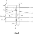
- FIG. 2 represents a graph 30 schematically showing the evolution of signal values and electrical voltages during the operation of the device 2, as a function of time (denoted “t” on the abscissa axis).
- graph 30 represents the evolution of the status signal (ENA), of the voltage across the capacitor 10 (denoted Vcap), of the voltage pulse delivered by the pulse generator 8 (denoted “Relay voltage ”) and the signal (here denoted "Status_WD”) indicating that relay 12 has changed state.
- device 2 is connected to a switching device.
- An input electrical voltage (for example present between the 15V and 0V pins of connector 4) is received from the switching device.
- the status signal remains at the low value.
- step S100 the status signal received from connector 4 changes value, for example following a change of state of the switching device, as visible on the figure 2 (reference 32).
- step S102 the current limiting circuit 6 authorizes the charging of the capacitor 10.
- the voltage Vcap increases gradually, as the capacitor 10 charges.
- the voltage Vcap across the capacitor reaches the predefined charge level, corresponding here to a trigger voltage Von (reference 34). This instant is for example reached after a predefined duration Tstart.
- the pulse generator 8 is activated and generates a voltage pulse from the energy stored in the capacitor 10 (reference 38). This gradually discharges capacitor 10.
- the duration of the pulse can be adjusted by programming the pulse generator 8 to stop when the charge level of the capacitor 10 reaches a second predefined threshold.
- this corresponds to a low voltage threshold noted Voff.
- the low voltage threshold Voff is lower than the trigger voltage Von.
- the trigger voltage Von is equal to 13V.
- the low voltage threshold Voff is equal to 8 Volts.
- the voltage pulse thus generated energizes coil 14 of relay 12 and forces contacts 16 and 18 to switch from their initial state.
- the second electrical contact 18 is switched to its closed state, and the first electrical contact 16 is switched to an open state.
- the change of state can be detected by a remote device connected to the dry contact formed by the terminals 20.
- the polarization circuit 22 generates an output signal (reference 36) under the effect of the opening of the second contact 16 and thanks to the electrical voltage Vcap which is always supplied by the capacitor 10.
- the status signal received at the input changes state again (reference 40).
- the current limiting circuit 6 stops powering the capacitor 10.
- the duration (denoted Tread) of this signal can be adjusted according to the mechanical characteristics of the relay 12,
- the duration (noted Toff) between the end of the output signal and the change of state of the ENA status signal received at the input can be adjusted as a function of characteristics of the ENA status signal and/or of characteristics of the control circuit of the switching device.
- the duration Toff can be chosen so as to impose a time delay linked to the ENA status signal dropping (towards its default low value) once it is certain that the switching device has actually changed of state.
- the steps could be performed in a different order. Some steps could be omitted.
- the example described does not preclude, in other embodiments, other steps being implemented jointly and/or sequentially with the steps described.
- the communication device 2 makes it possible to provide remote information on the state of the switching device to which it is connected via the dry electrical contact, which can be connected to one or more devices, thus allowing the switching device to be monitored remotely.
- the communication device has a simple design and is inexpensive to manufacture. It consumes only a very small amount of power to operate and does not need a self-contained electrical power source such as a battery, since it is electrically powered by the switching device to which it is connected. And thanks to its low energy consumption, the communication device avoids harming the proper functioning of the switching device and also avoids degrading its energy performance. Indeed, the switching device is itself optimized in terms of energy consumption and is not necessarily sized for such a task.
- the use of the capacitor 10 to polarize the second contact 16 makes it possible to generate the output signal RWD-read-status without consuming energy directly from the switching device.
- the device 2 is also independent of the switching device and can thus, in certain numerous embodiments, be mounted on different switching devices. existing switching devices, without the need to modify these devices. However, the device 2 can just as easily be used in numerous other applications, for example by being mounted on switching devices designed to accommodate it, or be offset on a fixing rail near the switching device when the latter is not natively designed to accommodate device 2.
- the components of the device 2 are housed in a housing 50, for example made of thermoformed plastic material.
- the housing 50 is preferably configured to be mounted on the housing of the switching device with which the device 2 is associated.
- the housing 50 includes fixing means, such as hooks, or screwable elements, or any suitable fixing device.
- the housing 50 can be configured to be mounted in an electrical panel, for example by being fixed or attached to a fixing rail, using appropriate fixing elements.
- the device 2 is mounted in a removable manner.
- the means of fixing the housing 50 are therefore shaped accordingly.
- the components of device 2 can be mounted on a support housed inside the housing 50, such as an epoxy resin plate, or any equivalent device.
- the device 2 is assembled from discrete components.
- references 52, 56 and 58 correspond respectively to connector 4, relay 12 and current limiting circuit 6.
- References 60, 62 and 64 correspond respectively to output terminals 20, reset button 24 and bias circuit 22.
- An additional connector 54 can be installed in the case where the device 2 is intended to be connected to the switching device via a wired connection following a so-called “daisy chain” topology in English.
- the pins of additional connector 54 are then connected to the respective pins of connector 4.
- the device 2 has compact dimensions.
- the housing 50 has a height less than or equal to 45mm and a width less than or equal to 20mm.
Landscapes
- Engineering & Computer Science (AREA)
- Power Engineering (AREA)
- Selective Calling Equipment (AREA)
- Remote Monitoring And Control Of Power-Distribution Networks (AREA)
- Relay Circuits (AREA)
Claims (10)
- Kommunikationsvorrichtung (2) mit niedrigem Energieverbrauch für ein elektrisches Schaltgerät, wie beispielsweise ein Schütz, das elektrische Schaltgerät umfassend einen Aktuator, der von einer Steuerschaltung angesteuert wird, die Kommunikationsvorrichtung (2) umfassend:- einen Verbinder (4), der geeignet ist, um mit der Steuerschaltung verbunden zu werden, um ein von der Steuerschaltung gesendetes Zustandssignal (Ena) zu empfangen und um eine von dem Schaltgerät bereitgestellte elektrische Versorgungsspannung (15V) zu empfangen;- einen Kondensator (10), der konfiguriert ist, um aus der von dem Eingangsverbinder empfangenen Versorgungsspannung aufgeladen zu werden, wenn das Zustandssignal einen vordefinierten Wert annimmt;- ein Relais (12), umfassend einen normal offenen (NO) elektrischen Kontakt (18), der mit Ausgangsanschlüssen (20) der Kommunikationsvorrichtung verbunden ist, um einen trockenen elektrischen Kontakt zu bilden;- einen Impulsgenerator (8), der von dem Kondensator gespeist wird und konfiguriert ist, um das bistabile Relais zu erregen und dadurch den elektrischen Kontakt (18) umzuschalten, wenn der Kondensator einen vordefinierten Ladestand erreicht,dadurch gekennzeichnet, dass das Relais (12) ein bistabiles Relais (12) ist und dass die Kommunikationsvorrichtung (2) Folgendes umfasst:- ein Gehäuse (50), wobei die Bestandteile der Kommunikationsvorrichtung (2) in dem Gehäuse untergebracht sind, wobei das Gehäuse konfiguriert ist, um an dem Gehäuse des Schaltgeräts, mit dem die Kommunikationsvorrichtung (2) assoziiert ist, montiert zu werden.
- Kommunikationsvorrichtung nach Anspruch 1, die eine Strombegrenzungsschaltung (6) umfasst, die zwischen dem Eingangsverbinder und dem Kondensator (10) verbunden ist, wobei die Strombegrenzungsschaltung (6) konfiguriert ist, um den Kondensator nur dann aus der empfangenen elektrischen Versorgungsspannung zu speisen, wenn das Zustandssignal den vordefinierten Wert annimmt.
- Kommunikationsvorrichtung nach einem der vorherigen Ansprüche, wobei das Relais (12) einen zusätzlichen elektrischen Kontakt (16) umfasst, der mit einem Ausgang des Verbinders (4) gekoppelt ist, um ein Signal (RWD-read-status) zu senden, das angibt, dass das Relais seinen Zustand geändert hat.
- Kommunikationsvorrichtung nach Anspruch 3, wobei der zusätzliche elektrische Kontakt durch die von dem Kondensator (10) gelieferte Spannung vorgeladen wird.
- Kommunikationsvorrichtung nach Anspruch 3 oder Anspruch 4, wobei der zusätzliche elektrische Kontakt (16) ein Öffnerkontakt (NC) ist.
- Kommunikationsvorrichtung nach einem der vorherigen Ansprüche, wobei die von dem Schaltgerät bereitgestellte elektrische Versorgungsspannung (15V) kleiner als oder gleich wie 15 Volt ist.
- Kommunikationsvorrichtung nach einem der vorherigen Ansprüche, wobei die elektrische Leistung, die von dem Schaltgerät (2) während des Betriebs aufgenommen wird, weniger als 1 Watt und vorzugsweise weniger als 15 mW ist.
- Kommunikationsvorrichtung nach einem der vorherigen Ansprüche, die eine Rücksetztaste (24) umfasst, die mit dem Relais (12) gekoppelt ist und mit der das Relais (12) manuell in einen vordefinierten Zustand zurückgesetzt werden kann.
- Kommunikationsvorrichtung nach einem der vorherigen Ansprüche, wobei der vordefinierte Ladestand des Kondensators einer elektrischen Spannung zwischen 3 Volt und 20 Volt entspricht.
- System, umfassend ein elektrisches Schaltgerät, wie beispielsweise ein Schütz, und eine Kommunikationsvorrichtung nach einem der vorherigen Ansprüche, das elektrische Schaltgerät umfassend einen von einer Steuerschaltung gesteuerten Aktuator, wobei der Verbinder (4) mit der Steuerschaltung verbunden ist, um ein von der Steuerschaltung gesendetes Zustandssignal (Ena) zu empfangen und um eine von dem Schaltgerät bereitgestellte elektrische Versorgungsspannung (15V) zu empfangen.
Applications Claiming Priority (1)
| Application Number | Priority Date | Filing Date | Title |
|---|---|---|---|
| FR2009954A FR3114680B1 (fr) | 2020-09-30 | 2020-09-30 | Dispositif de communication pour un appareil de commutation électrique |
Publications (2)
| Publication Number | Publication Date |
|---|---|
| EP3979282A1 EP3979282A1 (de) | 2022-04-06 |
| EP3979282B1 true EP3979282B1 (de) | 2024-07-24 |
Family
ID=73643092
Family Applications (1)
| Application Number | Title | Priority Date | Filing Date |
|---|---|---|---|
| EP21199675.6A Active EP3979282B1 (de) | 2020-09-30 | 2021-09-29 | Kommunikationsvorrichtung für ein elektrisches schaltgerät |
Country Status (5)
| Country | Link |
|---|---|
| US (1) | US11881370B2 (de) |
| EP (1) | EP3979282B1 (de) |
| CN (1) | CN114336955A (de) |
| ES (1) | ES2987851T3 (de) |
| FR (1) | FR3114680B1 (de) |
Family Cites Families (8)
| Publication number | Priority date | Publication date | Assignee | Title |
|---|---|---|---|---|
| FR2579821B1 (fr) * | 1985-03-26 | 1987-05-15 | Merlin Gerin | Appareil de coupure multipolaire a telecommande |
| US8356761B2 (en) * | 2008-07-31 | 2013-01-22 | Siemens Industry, Inc. | Communication powered building automation system actuator |
| US9300125B2 (en) * | 2010-06-30 | 2016-03-29 | Eaton Corporation | Apparatus for energizing a protective device, and associated method |
| US8760103B2 (en) * | 2011-09-30 | 2014-06-24 | Honeywell International Inc. | Actuator power control circuit having fail-safe bypass switching |
| US9064660B2 (en) * | 2012-03-22 | 2015-06-23 | Technology Logic International Limited | Remote controlled interactive power switch |
| US10498395B2 (en) * | 2016-01-04 | 2019-12-03 | Hitachi Automotive Systems, Ltd. | Power line communication apparatus and electronic control apparatus including power line communication apparatus |
| FR3055465B1 (fr) | 2016-08-23 | 2019-11-22 | Schneider Electric Industries Sas | Declencheur commandable pour un disjoncteur electrique |
| EP3863172B1 (de) * | 2018-10-04 | 2026-03-04 | Weg Drives & Controls - Automação LTDA | Hilfsmodulanordnung für eine starterbaugruppe für elektromotoren |
-
2020
- 2020-09-30 FR FR2009954A patent/FR3114680B1/fr active Active
-
2021
- 2021-09-23 US US17/482,615 patent/US11881370B2/en active Active
- 2021-09-29 EP EP21199675.6A patent/EP3979282B1/de active Active
- 2021-09-29 CN CN202111150188.4A patent/CN114336955A/zh active Pending
- 2021-09-29 ES ES21199675T patent/ES2987851T3/es active Active
Also Published As
| Publication number | Publication date |
|---|---|
| US20220102099A1 (en) | 2022-03-31 |
| FR3114680A1 (fr) | 2022-04-01 |
| EP3979282A1 (de) | 2022-04-06 |
| CN114336955A (zh) | 2022-04-12 |
| US11881370B2 (en) | 2024-01-23 |
| FR3114680B1 (fr) | 2023-01-20 |
| ES2987851T3 (es) | 2024-11-18 |
Similar Documents
| Publication | Publication Date | Title |
|---|---|---|
| CA2692300C (fr) | Procede et systeme de gestion de coupures d'alimentation electrique a bord d'un aeronef | |
| FR2462749A1 (fr) | Detecteur d'incendie et systeme avertisseur d'incendie utilisant un tel detecteur | |
| EP3979282B1 (de) | Kommunikationsvorrichtung für ein elektrisches schaltgerät | |
| EP2363939B1 (de) | Unterbrechungsfreie Wechselstromversorgung einer Installation und Verfahren dazu | |
| EP4174815B1 (de) | Drahtlose steuerungsvorrichtungen | |
| WO2012168469A1 (fr) | Dispositif d'alimentation électrique continue stabilisé à sorties multiples | |
| FR3011137A1 (fr) | Prise electrique comportant des moyens d'identification et des moyens de coupure associes | |
| FR3076064A1 (fr) | Appareil auxiliaire pour appareillage de protection electrique | |
| EP2051349A1 (de) | Vorrichtung zur Aufrechterhaltung der Einspeisspannung in elektrische Geräte | |
| EP4088294B1 (de) | Geschützter schalter | |
| FR2956534A1 (fr) | Dispositif de maintien de l'alimentation d'un appareil electrique raccorde a un reseau electrique fonctionnant selon des periodes tarifaires par contacteur ou programmateur | |
| EP0643310B1 (de) | Einrichtung zur Überwachung der Entladung einer Vielzahl in Reihe geschalteter Batterien | |
| FR3106447A1 (fr) | Element de stockage d’energie electrique et alimentation sauvegardee associee | |
| FR2970609A1 (fr) | Detection de la deconnexion d'une batterie | |
| WO2003083288A1 (fr) | Circuit de commande electronique d'un contacteur de demarreur de vehicule automobile. | |
| FR2863402A1 (fr) | Procede et dispositif de surveillance et de securite d'une minuterie | |
| FR2636478A1 (fr) | Dispositif de controle et de charge d'une batterie d'accumulateurs notamment | |
| FR2999353B1 (fr) | Dispositif d'eclairage de securite a autonomie amelioree | |
| FR2896100A1 (fr) | Dispositif de controle d'au moins deux batteries d'accumulateur et procedes de charge a l'aide d'un tel dispositif de controle | |
| FR2710205A1 (fr) | Procédé de distribution contrôlée d'énergie et dispositif pour la mise en Óoeuvre du procédé. | |
| BE882779A (fr) | Dispositif de controle d'electrolyte d'accumulateur | |
| EP4075471A1 (de) | Elektrisches hilfsschutzmodul, elektrisches schutzgerät mit einem solchen modul und entsprechendes betriebsverfahren | |
| FR2906418A1 (fr) | Boitier electronique destine a etre monte sur une roue de vehicule en vue de la mesure d'au moins un parametre de fonctionnement de la dite roue de vehicule | |
| FR2896346A1 (fr) | Ensemble comprenant un coupe-circuit d'une batterie d'alimentation qui comporte un circuit electronique adapte a etre isole de la batterie d'alimentation | |
| FR2778507A1 (fr) | Circuit de securite de batterie |
Legal Events
| Date | Code | Title | Description |
|---|---|---|---|
| PUAI | Public reference made under article 153(3) epc to a published international application that has entered the european phase |
Free format text: ORIGINAL CODE: 0009012 |
|
| STAA | Information on the status of an ep patent application or granted ep patent |
Free format text: STATUS: THE APPLICATION HAS BEEN PUBLISHED |
|
| AK | Designated contracting states |
Kind code of ref document: A1 Designated state(s): AL AT BE BG CH CY CZ DE DK EE ES FI FR GB GR HR HU IE IS IT LI LT LU LV MC MK MT NL NO PL PT RO RS SE SI SK SM TR |
|
| STAA | Information on the status of an ep patent application or granted ep patent |
Free format text: STATUS: REQUEST FOR EXAMINATION WAS MADE |
|
| 17P | Request for examination filed |
Effective date: 20220906 |
|
| RBV | Designated contracting states (corrected) |
Designated state(s): AL AT BE BG CH CY CZ DE DK EE ES FI FR GB GR HR HU IE IS IT LI LT LU LV MC MK MT NL NO PL PT RO RS SE SI SK SM TR |
|
| GRAP | Despatch of communication of intention to grant a patent |
Free format text: ORIGINAL CODE: EPIDOSNIGR1 |
|
| STAA | Information on the status of an ep patent application or granted ep patent |
Free format text: STATUS: GRANT OF PATENT IS INTENDED |
|
| RIC1 | Information provided on ipc code assigned before grant |
Ipc: H01H 47/32 20060101ALI20240118BHEP Ipc: H01H 47/00 20060101ALI20240118BHEP Ipc: H01H 9/54 20060101ALI20240118BHEP Ipc: H01H 9/16 20060101AFI20240118BHEP |
|
| INTG | Intention to grant announced |
Effective date: 20240216 |
|
| GRAS | Grant fee paid |
Free format text: ORIGINAL CODE: EPIDOSNIGR3 |
|
| GRAA | (expected) grant |
Free format text: ORIGINAL CODE: 0009210 |
|
| STAA | Information on the status of an ep patent application or granted ep patent |
Free format text: STATUS: THE PATENT HAS BEEN GRANTED |
|
| AK | Designated contracting states |
Kind code of ref document: B1 Designated state(s): AL AT BE BG CH CY CZ DE DK EE ES FI FR GB GR HR HU IE IS IT LI LT LU LV MC MK MT NL NO PL PT RO RS SE SI SK SM TR |
|
| REG | Reference to a national code |
Ref country code: GB Ref legal event code: FG4D Free format text: NOT ENGLISH |
|
| REG | Reference to a national code |
Ref country code: CH Ref legal event code: EP |
|
| REG | Reference to a national code |
Ref country code: DE Ref legal event code: R096 Ref document number: 602021016049 Country of ref document: DE |
|
| REG | Reference to a national code |
Ref country code: IE Ref legal event code: FG4D Free format text: LANGUAGE OF EP DOCUMENT: FRENCH |
|
| REG | Reference to a national code |
Ref country code: LT Ref legal event code: MG9D |
|
| REG | Reference to a national code |
Ref country code: ES Ref legal event code: FG2A Ref document number: 2987851 Country of ref document: ES Kind code of ref document: T3 Effective date: 20241118 |
|
| REG | Reference to a national code |
Ref country code: NL Ref legal event code: MP Effective date: 20240724 |
|
| PG25 | Lapsed in a contracting state [announced via postgrant information from national office to epo] |
Ref country code: PT Free format text: LAPSE BECAUSE OF FAILURE TO SUBMIT A TRANSLATION OF THE DESCRIPTION OR TO PAY THE FEE WITHIN THE PRESCRIBED TIME-LIMIT Effective date: 20241125 |
|
| REG | Reference to a national code |
Ref country code: AT Ref legal event code: MK05 Ref document number: 1707130 Country of ref document: AT Kind code of ref document: T Effective date: 20240724 |
|
| PG25 | Lapsed in a contracting state [announced via postgrant information from national office to epo] |
Ref country code: NL Free format text: LAPSE BECAUSE OF FAILURE TO SUBMIT A TRANSLATION OF THE DESCRIPTION OR TO PAY THE FEE WITHIN THE PRESCRIBED TIME-LIMIT Effective date: 20240724 |
|
| PG25 | Lapsed in a contracting state [announced via postgrant information from national office to epo] |
Ref country code: PT Free format text: LAPSE BECAUSE OF FAILURE TO SUBMIT A TRANSLATION OF THE DESCRIPTION OR TO PAY THE FEE WITHIN THE PRESCRIBED TIME-LIMIT Effective date: 20241125 Ref country code: NL Free format text: LAPSE BECAUSE OF FAILURE TO SUBMIT A TRANSLATION OF THE DESCRIPTION OR TO PAY THE FEE WITHIN THE PRESCRIBED TIME-LIMIT Effective date: 20240724 |
|
| PG25 | Lapsed in a contracting state [announced via postgrant information from national office to epo] |
Ref country code: NO Free format text: LAPSE BECAUSE OF FAILURE TO SUBMIT A TRANSLATION OF THE DESCRIPTION OR TO PAY THE FEE WITHIN THE PRESCRIBED TIME-LIMIT Effective date: 20241024 |
|
| PG25 | Lapsed in a contracting state [announced via postgrant information from national office to epo] |
Ref country code: FI Free format text: LAPSE BECAUSE OF FAILURE TO SUBMIT A TRANSLATION OF THE DESCRIPTION OR TO PAY THE FEE WITHIN THE PRESCRIBED TIME-LIMIT Effective date: 20240724 Ref country code: GR Free format text: LAPSE BECAUSE OF FAILURE TO SUBMIT A TRANSLATION OF THE DESCRIPTION OR TO PAY THE FEE WITHIN THE PRESCRIBED TIME-LIMIT Effective date: 20241025 Ref country code: PL Free format text: LAPSE BECAUSE OF FAILURE TO SUBMIT A TRANSLATION OF THE DESCRIPTION OR TO PAY THE FEE WITHIN THE PRESCRIBED TIME-LIMIT Effective date: 20240724 |
|
| PG25 | Lapsed in a contracting state [announced via postgrant information from national office to epo] |
Ref country code: BG Free format text: LAPSE BECAUSE OF FAILURE TO SUBMIT A TRANSLATION OF THE DESCRIPTION OR TO PAY THE FEE WITHIN THE PRESCRIBED TIME-LIMIT Effective date: 20240724 |
|
| PG25 | Lapsed in a contracting state [announced via postgrant information from national office to epo] |
Ref country code: LV Free format text: LAPSE BECAUSE OF FAILURE TO SUBMIT A TRANSLATION OF THE DESCRIPTION OR TO PAY THE FEE WITHIN THE PRESCRIBED TIME-LIMIT Effective date: 20240724 |
|
| PG25 | Lapsed in a contracting state [announced via postgrant information from national office to epo] |
Ref country code: IS Free format text: LAPSE BECAUSE OF FAILURE TO SUBMIT A TRANSLATION OF THE DESCRIPTION OR TO PAY THE FEE WITHIN THE PRESCRIBED TIME-LIMIT Effective date: 20241124 Ref country code: AT Free format text: LAPSE BECAUSE OF FAILURE TO SUBMIT A TRANSLATION OF THE DESCRIPTION OR TO PAY THE FEE WITHIN THE PRESCRIBED TIME-LIMIT Effective date: 20240724 |
|
| PG25 | Lapsed in a contracting state [announced via postgrant information from national office to epo] |
Ref country code: HR Free format text: LAPSE BECAUSE OF FAILURE TO SUBMIT A TRANSLATION OF THE DESCRIPTION OR TO PAY THE FEE WITHIN THE PRESCRIBED TIME-LIMIT Effective date: 20240724 |
|
| PG25 | Lapsed in a contracting state [announced via postgrant information from national office to epo] |
Ref country code: RS Free format text: LAPSE BECAUSE OF FAILURE TO SUBMIT A TRANSLATION OF THE DESCRIPTION OR TO PAY THE FEE WITHIN THE PRESCRIBED TIME-LIMIT Effective date: 20241024 |
|
| PG25 | Lapsed in a contracting state [announced via postgrant information from national office to epo] |
Ref country code: RS Free format text: LAPSE BECAUSE OF FAILURE TO SUBMIT A TRANSLATION OF THE DESCRIPTION OR TO PAY THE FEE WITHIN THE PRESCRIBED TIME-LIMIT Effective date: 20241024 Ref country code: PL Free format text: LAPSE BECAUSE OF FAILURE TO SUBMIT A TRANSLATION OF THE DESCRIPTION OR TO PAY THE FEE WITHIN THE PRESCRIBED TIME-LIMIT Effective date: 20240724 Ref country code: NO Free format text: LAPSE BECAUSE OF FAILURE TO SUBMIT A TRANSLATION OF THE DESCRIPTION OR TO PAY THE FEE WITHIN THE PRESCRIBED TIME-LIMIT Effective date: 20241024 Ref country code: LV Free format text: LAPSE BECAUSE OF FAILURE TO SUBMIT A TRANSLATION OF THE DESCRIPTION OR TO PAY THE FEE WITHIN THE PRESCRIBED TIME-LIMIT Effective date: 20240724 Ref country code: IS Free format text: LAPSE BECAUSE OF FAILURE TO SUBMIT A TRANSLATION OF THE DESCRIPTION OR TO PAY THE FEE WITHIN THE PRESCRIBED TIME-LIMIT Effective date: 20241124 Ref country code: HR Free format text: LAPSE BECAUSE OF FAILURE TO SUBMIT A TRANSLATION OF THE DESCRIPTION OR TO PAY THE FEE WITHIN THE PRESCRIBED TIME-LIMIT Effective date: 20240724 Ref country code: GR Free format text: LAPSE BECAUSE OF FAILURE TO SUBMIT A TRANSLATION OF THE DESCRIPTION OR TO PAY THE FEE WITHIN THE PRESCRIBED TIME-LIMIT Effective date: 20241025 Ref country code: FI Free format text: LAPSE BECAUSE OF FAILURE TO SUBMIT A TRANSLATION OF THE DESCRIPTION OR TO PAY THE FEE WITHIN THE PRESCRIBED TIME-LIMIT Effective date: 20240724 Ref country code: BG Free format text: LAPSE BECAUSE OF FAILURE TO SUBMIT A TRANSLATION OF THE DESCRIPTION OR TO PAY THE FEE WITHIN THE PRESCRIBED TIME-LIMIT Effective date: 20240724 Ref country code: AT Free format text: LAPSE BECAUSE OF FAILURE TO SUBMIT A TRANSLATION OF THE DESCRIPTION OR TO PAY THE FEE WITHIN THE PRESCRIBED TIME-LIMIT Effective date: 20240724 |
|
| PG25 | Lapsed in a contracting state [announced via postgrant information from national office to epo] |
Ref country code: RO Free format text: LAPSE BECAUSE OF FAILURE TO SUBMIT A TRANSLATION OF THE DESCRIPTION OR TO PAY THE FEE WITHIN THE PRESCRIBED TIME-LIMIT Effective date: 20240724 Ref country code: SM Free format text: LAPSE BECAUSE OF FAILURE TO SUBMIT A TRANSLATION OF THE DESCRIPTION OR TO PAY THE FEE WITHIN THE PRESCRIBED TIME-LIMIT Effective date: 20240724 Ref country code: DK Free format text: LAPSE BECAUSE OF FAILURE TO SUBMIT A TRANSLATION OF THE DESCRIPTION OR TO PAY THE FEE WITHIN THE PRESCRIBED TIME-LIMIT Effective date: 20240724 |
|
| PG25 | Lapsed in a contracting state [announced via postgrant information from national office to epo] |
Ref country code: MC Free format text: LAPSE BECAUSE OF FAILURE TO SUBMIT A TRANSLATION OF THE DESCRIPTION OR TO PAY THE FEE WITHIN THE PRESCRIBED TIME-LIMIT Effective date: 20240724 Ref country code: EE Free format text: LAPSE BECAUSE OF FAILURE TO SUBMIT A TRANSLATION OF THE DESCRIPTION OR TO PAY THE FEE WITHIN THE PRESCRIBED TIME-LIMIT Effective date: 20240724 |
|
| PG25 | Lapsed in a contracting state [announced via postgrant information from national office to epo] |
Ref country code: CZ Free format text: LAPSE BECAUSE OF FAILURE TO SUBMIT A TRANSLATION OF THE DESCRIPTION OR TO PAY THE FEE WITHIN THE PRESCRIBED TIME-LIMIT Effective date: 20240724 |
|
| REG | Reference to a national code |
Ref country code: DE Ref legal event code: R097 Ref document number: 602021016049 Country of ref document: DE |
|
| PG25 | Lapsed in a contracting state [announced via postgrant information from national office to epo] |
Ref country code: SK Free format text: LAPSE BECAUSE OF FAILURE TO SUBMIT A TRANSLATION OF THE DESCRIPTION OR TO PAY THE FEE WITHIN THE PRESCRIBED TIME-LIMIT Effective date: 20240724 |
|
| REG | Reference to a national code |
Ref country code: CH Ref legal event code: PL |
|
| PG25 | Lapsed in a contracting state [announced via postgrant information from national office to epo] |
Ref country code: LU Free format text: LAPSE BECAUSE OF NON-PAYMENT OF DUE FEES Effective date: 20240929 |
|
| PLBE | No opposition filed within time limit |
Free format text: ORIGINAL CODE: 0009261 |
|
| STAA | Information on the status of an ep patent application or granted ep patent |
Free format text: STATUS: NO OPPOSITION FILED WITHIN TIME LIMIT |
|
| 26N | No opposition filed |
Effective date: 20250425 |
|
| REG | Reference to a national code |
Ref country code: BE Ref legal event code: MM Effective date: 20240930 |
|
| PG25 | Lapsed in a contracting state [announced via postgrant information from national office to epo] |
Ref country code: BE Free format text: LAPSE BECAUSE OF NON-PAYMENT OF DUE FEES Effective date: 20240930 |
|
| PG25 | Lapsed in a contracting state [announced via postgrant information from national office to epo] |
Ref country code: CH Free format text: LAPSE BECAUSE OF NON-PAYMENT OF DUE FEES Effective date: 20240930 |
|
| PG25 | Lapsed in a contracting state [announced via postgrant information from national office to epo] |
Ref country code: IE Free format text: LAPSE BECAUSE OF NON-PAYMENT OF DUE FEES Effective date: 20240929 |
|
| PG25 | Lapsed in a contracting state [announced via postgrant information from national office to epo] |
Ref country code: SE Free format text: LAPSE BECAUSE OF FAILURE TO SUBMIT A TRANSLATION OF THE DESCRIPTION OR TO PAY THE FEE WITHIN THE PRESCRIBED TIME-LIMIT Effective date: 20240724 |
|
| PGFP | Annual fee paid to national office [announced via postgrant information from national office to epo] |
Ref country code: DE Payment date: 20250926 Year of fee payment: 5 |
|
| PGFP | Annual fee paid to national office [announced via postgrant information from national office to epo] |
Ref country code: IT Payment date: 20250922 Year of fee payment: 5 |
|
| PGFP | Annual fee paid to national office [announced via postgrant information from national office to epo] |
Ref country code: FR Payment date: 20250925 Year of fee payment: 5 |
|
| PG25 | Lapsed in a contracting state [announced via postgrant information from national office to epo] |
Ref country code: CY Free format text: LAPSE BECAUSE OF FAILURE TO SUBMIT A TRANSLATION OF THE DESCRIPTION OR TO PAY THE FEE WITHIN THE PRESCRIBED TIME-LIMIT; INVALID AB INITIO Effective date: 20210929 |
|
| PGFP | Annual fee paid to national office [announced via postgrant information from national office to epo] |
Ref country code: ES Payment date: 20251015 Year of fee payment: 5 |
|
| PG25 | Lapsed in a contracting state [announced via postgrant information from national office to epo] |
Ref country code: HU Free format text: LAPSE BECAUSE OF FAILURE TO SUBMIT A TRANSLATION OF THE DESCRIPTION OR TO PAY THE FEE WITHIN THE PRESCRIBED TIME-LIMIT; INVALID AB INITIO Effective date: 20210929 |