EP3979265B1 - Electric cable processing device - Google Patents
Electric cable processing device Download PDFInfo
- Publication number
- EP3979265B1 EP3979265B1 EP20814473.3A EP20814473A EP3979265B1 EP 3979265 B1 EP3979265 B1 EP 3979265B1 EP 20814473 A EP20814473 A EP 20814473A EP 3979265 B1 EP3979265 B1 EP 3979265B1
- Authority
- EP
- European Patent Office
- Prior art keywords
- electric wire
- nonconforming
- item
- conforming
- tray
- Prior art date
- Legal status (The legal status is an assumption and is not a legal conclusion. Google has not performed a legal analysis and makes no representation as to the accuracy of the status listed.)
- Active
Links
Images



Classifications
-
- H—ELECTRICITY
- H01—ELECTRIC ELEMENTS
- H01B—CABLES; CONDUCTORS; INSULATORS; SELECTION OF MATERIALS FOR THEIR CONDUCTIVE, INSULATING OR DIELECTRIC PROPERTIES
- H01B13/00—Apparatus or processes specially adapted for manufacturing conductors or cables
- H01B13/012—Apparatus or processes specially adapted for manufacturing conductors or cables for manufacturing wire harnesses
-
- B—PERFORMING OPERATIONS; TRANSPORTING
- B07—SEPARATING SOLIDS FROM SOLIDS; SORTING
- B07C—POSTAL SORTING; SORTING INDIVIDUAL ARTICLES, OR BULK MATERIAL FIT TO BE SORTED PIECE-MEAL, e.g. BY PICKING
- B07C5/00—Sorting according to a characteristic or feature of the articles or material being sorted, e.g. by control effected by devices which detect or measure such characteristic or feature; Sorting by manually actuated devices, e.g. switches
- B07C5/36—Sorting apparatus characterised by the means used for distribution
-
- B—PERFORMING OPERATIONS; TRANSPORTING
- B23—MACHINE TOOLS; METAL-WORKING NOT OTHERWISE PROVIDED FOR
- B23Q—DETAILS, COMPONENTS, OR ACCESSORIES FOR MACHINE TOOLS, e.g. ARRANGEMENTS FOR COPYING OR CONTROLLING; MACHINE TOOLS IN GENERAL CHARACTERISED BY THE CONSTRUCTION OF PARTICULAR DETAILS OR COMPONENTS; COMBINATIONS OR ASSOCIATIONS OF METAL-WORKING MACHINES, NOT DIRECTED TO A PARTICULAR RESULT
- B23Q7/00—Arrangements for handling work specially combined with or arranged in, or specially adapted for use in connection with, machine tools, e.g. for conveying, loading, positioning, discharging, sorting
- B23Q7/12—Sorting arrangements
-
- H—ELECTRICITY
- H01—ELECTRIC ELEMENTS
- H01B—CABLES; CONDUCTORS; INSULATORS; SELECTION OF MATERIALS FOR THEIR CONDUCTIVE, INSULATING OR DIELECTRIC PROPERTIES
- H01B13/00—Apparatus or processes specially adapted for manufacturing conductors or cables
- H01B13/0003—Apparatus or processes specially adapted for manufacturing conductors or cables for feeding conductors or cables
-
- H—ELECTRICITY
- H01—ELECTRIC ELEMENTS
- H01R—ELECTRICALLY-CONDUCTIVE CONNECTIONS; STRUCTURAL ASSOCIATIONS OF A PLURALITY OF MUTUALLY-INSULATED ELECTRICAL CONNECTING ELEMENTS; COUPLING DEVICES; CURRENT COLLECTORS
- H01R43/00—Apparatus or processes specially adapted for manufacturing, assembling, maintaining, or repairing of line connectors or current collectors or for joining electric conductors
- H01R43/28—Apparatus or processes specially adapted for manufacturing, assembling, maintaining, or repairing of line connectors or current collectors or for joining electric conductors for wire processing before connecting to contact members, not provided for in groups H01R43/02 - H01R43/26
-
- H—ELECTRICITY
- H02—GENERATION; CONVERSION OR DISTRIBUTION OF ELECTRIC POWER
- H02G—INSTALLATION OF ELECTRIC CABLES OR LINES, OR OF COMBINED OPTICAL AND ELECTRIC CABLES OR LINES
- H02G1/00—Methods or apparatus specially adapted for installing, maintaining, repairing or dismantling electric cables or lines
- H02G1/12—Methods or apparatus specially adapted for installing, maintaining, repairing or dismantling electric cables or lines for removing insulation or armouring from cables, e.g. from the end thereof
- H02G1/1202—Methods or apparatus specially adapted for installing, maintaining, repairing or dismantling electric cables or lines for removing insulation or armouring from cables, e.g. from the end thereof by cutting and withdrawing insulation
- H02G1/1248—Machines
- H02G1/1251—Machines the cutting element not rotating about the wire or cable
- H02G1/1253—Machines the cutting element not rotating about the wire or cable making a transverse cut
- H02G1/1256—Machines the cutting element not rotating about the wire or cable making a transverse cut using wire or cable-clamping means
-
- Y—GENERAL TAGGING OF NEW TECHNOLOGICAL DEVELOPMENTS; GENERAL TAGGING OF CROSS-SECTIONAL TECHNOLOGIES SPANNING OVER SEVERAL SECTIONS OF THE IPC; TECHNICAL SUBJECTS COVERED BY FORMER USPC CROSS-REFERENCE ART COLLECTIONS [XRACs] AND DIGESTS
- Y10—TECHNICAL SUBJECTS COVERED BY FORMER USPC
- Y10T—TECHNICAL SUBJECTS COVERED BY FORMER US CLASSIFICATION
- Y10T29/00—Metal working
- Y10T29/51—Plural diverse manufacturing apparatus including means for metal shaping or assembling
- Y10T29/5136—Separate tool stations for selective or successive operation on work
- Y10T29/5137—Separate tool stations for selective or successive operation on work including assembling or disassembling station
- Y10T29/5139—Separate tool stations for selective or successive operation on work including assembling or disassembling station and means to sever work prior to disassembling
- Y10T29/514—Separate tool stations for selective or successive operation on work including assembling or disassembling station and means to sever work prior to disassembling comprising means to strip insulation from wire
-
- Y—GENERAL TAGGING OF NEW TECHNOLOGICAL DEVELOPMENTS; GENERAL TAGGING OF CROSS-SECTIONAL TECHNOLOGIES SPANNING OVER SEVERAL SECTIONS OF THE IPC; TECHNICAL SUBJECTS COVERED BY FORMER USPC CROSS-REFERENCE ART COLLECTIONS [XRACs] AND DIGESTS
- Y10—TECHNICAL SUBJECTS COVERED BY FORMER USPC
- Y10T—TECHNICAL SUBJECTS COVERED BY FORMER US CLASSIFICATION
- Y10T29/00—Metal working
- Y10T29/51—Plural diverse manufacturing apparatus including means for metal shaping or assembling
- Y10T29/5187—Wire working
-
- Y—GENERAL TAGGING OF NEW TECHNOLOGICAL DEVELOPMENTS; GENERAL TAGGING OF CROSS-SECTIONAL TECHNOLOGIES SPANNING OVER SEVERAL SECTIONS OF THE IPC; TECHNICAL SUBJECTS COVERED BY FORMER USPC CROSS-REFERENCE ART COLLECTIONS [XRACs] AND DIGESTS
- Y10—TECHNICAL SUBJECTS COVERED BY FORMER USPC
- Y10T—TECHNICAL SUBJECTS COVERED BY FORMER US CLASSIFICATION
- Y10T29/00—Metal working
- Y10T29/51—Plural diverse manufacturing apparatus including means for metal shaping or assembling
- Y10T29/5193—Electrical connector or terminal
-
- Y—GENERAL TAGGING OF NEW TECHNOLOGICAL DEVELOPMENTS; GENERAL TAGGING OF CROSS-SECTIONAL TECHNOLOGIES SPANNING OVER SEVERAL SECTIONS OF THE IPC; TECHNICAL SUBJECTS COVERED BY FORMER USPC CROSS-REFERENCE ART COLLECTIONS [XRACs] AND DIGESTS
- Y10—TECHNICAL SUBJECTS COVERED BY FORMER USPC
- Y10T—TECHNICAL SUBJECTS COVERED BY FORMER US CLASSIFICATION
- Y10T29/00—Metal working
- Y10T29/53—Means to assemble or disassemble
- Y10T29/5313—Means to assemble electrical device
- Y10T29/532—Conductor
- Y10T29/53209—Terminal or connector
Definitions
- the present invention relates to electric wire processing apparatuses.
- Electric wire processing apparatuses to perform various processes on electric wires are known in the related art.
- a known electric wire processing apparatus performs a process, such as cutting, insulator stripping, seal fitting, or terminal crimping, on electric wires each including a core and an insulator surrounding the core.
- Another known electric wire processing apparatus is configured to detect whether electric wires have been processed properly and collect the electric wires such that the electric wires are sorted into conforming and nonconforming items.
- JP 2011-210460 A discloses such an electric wire processing apparatus.
- the electric wire processing apparatus disclosed in JP 2011-210460 A includes: a clamp that turns while gripping one end of an electric wire; a product tray to collect a conforming item; and a nonconforming item tray to collect a nonconforming item.
- the electric wire processing apparatus collects conforming and nonconforming items into different trays so as to prevent mixing of the conforming and nonconforming items.
- Patent Literature 2 provides a further electric wire processing apparatus according to the prior art.
- the nonconforming item may temporarily run onto a boundary region between the nonconforming item tray and the product tray while being collected into the nonconforming item tray, and then the first end may be pulled toward the second end and transferred from the nonconforming item tray to the product tray.
- the nonconforming item may be collected into the product tray by mistake.
- the above-described apparatus may thus fail to appropriately sort a long electric wire into a conforming or nonconforming item.
- the present invention has been made in view of the above points, and its object is to provide an electric wire processing apparatus that would be able to collect an electric wire such that the electric wire is appropriately sorted into a conforming or nonconforming item if the electric wire is long.
- An electric wire processing apparatus disclosed herein includes: a processor to perform a predetermined process on an electric wire including a first end and a second end; a conforming/nonconforming determiner to determine whether the process has been performed successfully; a clamp to grip a portion of the electric wire adjacent to the first end, the clamp being movable so as to convey the first end of the electric wire; a conforming item collector disposed under a movement path for the first end of the electric wire that is being conveyed by the clamp, the conforming item collector being configured to collect a first end side portion of the electric wire determined to be a conforming item by the conforming/nonconforming determiner; a nonconforming item collector disposed under the movement path for the first end of the electric wire that is being conveyed by the clamp, the nonconforming item collector being configured to collect a first end side portion of the electric wire determined to be a nonconforming item by the conforming/nonconforming determiner; a shared collector disposed toward the second end of the electric wire relative to the conforming item
- the electric wire processing apparatus described above causes the portion of the electric wire adjacent to the first end to be gripped by the clamp and conveyed in accordance with movement of the clamp.
- the first end side portion of the electric wire determined to be conforming by the conforming/nonconforming determiner (hereinafter simply referred to as a "conforming item") is collected into the conforming item collector.
- the first end side portion of the electric wire determined to be nonconforming by the conforming/nonconforming determiner (hereinafter simply referred to as a "nonconforming item”) is collected into the nonconforming item collector.
- the conforming and nonconforming items are collected such that the first end side portion of the conforming item and the first end side portion of the nonconforming item are accurately sorted from each other.
- the electric wire processing apparatus thus eliminates the possibility of collecting the portion of the electric wire adjacent to the second end into a wrong place. Accordingly, the electric wire processing apparatus reduces the possibility that the portion of the conforming item adjacent to the first end will be pulled toward the second end and transferred from the conforming item collector to the nonconforming item collector. The electric wire processing apparatus also reduces the possibility that the portion of the nonconforming item adjacent to the first end will be pulled toward the second end and transferred from the nonconforming item collector to the conforming item collector. When the electric wire is long, the electric wire processing apparatus does not necessarily have to sort an entirety of the electric wire.
- the electric wire processing apparatus is able to make a clear distinction between the conforming and nonconforming items as a whole by sorting a portion of the electric wire.
- the electric wire processing apparatus accurately sorts the first end side portion of the conforming item from the first end side portion of the nonconforming item and is thus able to make a clear distinction between the conforming and nonconforming items as a whole. Consequently, the electric wire processing apparatus is able to appropriately sort the conforming item from the nonconforming item.
- the processor is configured to perform the predetermined process on the first end of the electric wire gripped by the clamp.
- the clamp may receive the processed electric wire from another clamp that grips the electric wire during processing of the electric wire by the processor.
- the clamp grips the electric wire during processing of the electric wire by the processor. The above embodiment thus eliminates the need to pass the electric wire between the clamps or reduces the number of times the electric wire is to be passed between the clamps, resulting in increased electric wire processing efficiency.
- the electric wire processing apparatus includes a partition wall disposed between the conforming item collector and the nonconforming item collector and extending in an up-down direction.
- the first end side portion of the conforming item is accurately sorted from the first end side portion of the nonconforming item with the partition wall.
- an upper edge of the partition wall includes an inclined portion that inclines downward as it extends toward the shared collector.
- the electric wire that is long may sway when the electric wire falls upon being released from the clamp.
- the portion of the electric wire adjacent to the first end may bend and fall on the upper edge of the partition wall.
- the upper edge of the partition wall includes the inclined portion.
- the conforming item collector includes: an upper collector to collect the first end side portion of the electric wire and allow the collected portion of the electric wire to fall; and a lower collector disposed under the upper collector, the lower collector being configured to collect the portion of the electric wire that has fallen from the upper collector.
- the first end side portion of the conforming item that has been collected into the upper collector is transferrable to the lower collector. Accordingly, during removal of the conforming item from the lower collector and the shared collector, the electric wire processing apparatus is able to collect the first end side portion of another conforming item into the upper collector. Consequently, the electric wire processing apparatus enables collection of one conforming item and removal of another conforming item to be carried out simultaneously, resulting in an increase in the efficiency of electric wire sorting operation.
- the electric wire is not limited to any particular type of electric wire.
- the process to be performed on the electric wire is not limited to any particular process.
- the electric wire may include: a core made of a conductor; and an insulator surrounding the core.
- the processor may include at least one of: a device to cut the electric wire so as to provide the first end; a device to strip the insulator from the first end of the electric wire; a device to fit a seal to the first end of the electric wire; and a device to crimp a terminal to the first end of the electric wire.
- the direction of movement of the clamp is not limited to any particular direction, the above-described effects will be particularly pronounced when the clamp is configured to turn around a vertical line.
- the present invention provides an electric wire processing apparatus that would be able to collect an electric wire such that the electric wire is appropriately sorted into a conforming or nonconforming item if the electric wire is long.
- FIG. 1 is a plan view schematically illustrating the arrangement of an electric wire processing apparatus 1 according to the present embodiment.
- the right and left sides in FIG. 1 are defined as the front and rear sides, respectively, and the upper and lower sides in FIG. 1 are defined as the right and left sides, respectively.
- These directions, however, are defined merely for the sake of convenience of description and do not limit, for example, where the electric wire processing apparatus 1 may be installed.
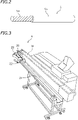
- an electric wire 5 is a "coated electric wire".
- the electric wire 5 includes: a core 5a made of a conductor, such as metal; and an insulator 5b made of a resin or other material surrounding the core 5a.
- the electric wire processing apparatus 1 includes: straightening rollers 6 to smooth the curves of the electric wire 5; a feeder 2 to feed the electric wire 5; clamps 3F and 3R to grip the electric wire 5; a conveyance belt 18 to convey the electric wire 5 forward; a cutter device 10; seal fitters 15F and 15R to fit waterproof seals (not illustrated) to the electric wire 5; terminal crimpers 4F and 4R to crimp terminals 7 to the electric wire 5; a collecting device 8 to collect the electric wire 5 that has been processed; and a controller 9.
- the feeder 2 is not limited to any particular arrangement.
- the feeder 2 includes: a pair of right front and right rear pulleys 2A; a right conveyance belt 2B wound around the right front and right rear pulleys 2A; a pair of left front and left rear pulleys 2A; and a left conveyance belt 2B wound around the left front and left rear pulleys 2A.
- at least one of the pulleys 2A is connected with a motor. Driving the motor rotates the pulleys 2A, causing the conveyance belts 2B to circulate. The electric wire 5 sandwiched between the right and left conveyance belts 2B is thus fed forward.
- the cutter device 10 includes: a cutting edge 11 to cut the electric wire 5; and stripping edges 12R and 12F to strip the insulator 5b from the electric wire 5.
- the stripping edge 12F, the cutting edge 11, and the stripping edge 12R are disposed side by side in a transverse direction.
- the electric wire processing apparatus 1 is able to perform the processes of: cutting the electric wire 5; stripping the insulator 5b from the electric wire 5; fitting waterproof seals to the electric wire 5; and crimping the terminals 7 to the ends of the electric wire 5.
- the cutting edge 11 is an example of a processor to cut the electric wire 5.
- the stripping edges 12R and 12F are each an example of a processor to strip the insulator 5b from the electric wire 5.
- the seal fitters 15F and 15R are each an example of a processor to fit a waterproof seal to the electric wire 5.
- the terminal crimpers 4F and 4R are each an example of a processor to crimp the terminal 7 to the end of the electric wire 5.
- the electric wire processing apparatus 1 does not necessarily have to perform all of the processes just mentioned.
- the electric wire processing apparatus includes a device to perform at least one of the processes.
- the conveyance belt 18 is disposed forward of the cutter device 10.
- the conveyance belt 18 is configured to feed the electric wire 5 forward in conjunction with the feeder 2.
- the conveyance belt 18 is configured to run forward when the feeder 2 feeds the electric wire 5 forward.
- a portion of the electric wire 5 is placed on the conveyance belt 18 and conveyed forward with the running of the conveyance belt 18.
- the clamps 3F and 3R are disposed forward of the feeder 2.
- the clamps 3F and 3R grip the electric wire 5 fed from the feeder 2.
- the clamps 3F and 3R are able to grip the electric wire 5 and release its grip on the electric wire 5.
- the clamp 3F is disposed rearward of the cutter device 10.
- the clamp 3R is disposed forward of the cutter device 10.
- the clamp 3F is configured to be able to turn around a turning center CF.
- the clamp 3R is configured to be able to turn around a turning center CR.
- Each of the turning centers CF and CR is a vertical line that extends vertically.
- the electric wire processing apparatus 1 includes: an actuator to open and close the clamp 3F (i.e., an actuator to cause the clamp 3F to grip the electric wire 5 and release its grip on the electric wire 5); an actuator to cause the clamp 3F to turn; an actuator to open and close the clamp 3R; and an actuator to cause the clamp 3R to turn.
- Such actuators are well known and will thus not be described any further.
- the clamp 3F turns while gripping the front end of the rear side electric wire 5 that has been cut, thus conveying the front end of the electric wire 5 to the stripping edge 12F, the seal fitter 15F, and the terminal crimper 4F.
- the clamp 3R turns while gripping the rear end of the front side electric wire 5 that has been cut, thus conveying the rear end of the electric wire 5 to the stripping edge 12R, the seal fitter 15R, and the terminal crimper 4R.
- the electric wire processing apparatus 1 includes a conforming/nonconforming determiner 14 to determine whether the electric wire 5 has been processed successfully.
- the conforming/nonconforming determiner 14 is configured to determine whether the electric wire 5 has been cut successfully, whether the electric wire 5 has been stripped of the insulator 5b successfully, whether a waterproof seal has been fitted to the electric wire 5 successfully, and whether a terminal has been crimped to the electric wire 5 successfully.
- the conforming/nonconforming determiner 14 does not necessarily have to make determinations on whether all of the cutting, stripping, waterproof seal fitting, and terminal crimping processes have been performed successfully but may be configured to make a determination on at least one of the processes. Such a determiner is well known and will thus not be described in detail.
- FIG. 3 is a perspective view of the collecting device 8.
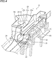
- FIG. 4 is an enlarged perspective view of the rear portion of the collecting device 8.
- the collecting device 8 includes: an upper tray 21; a lower tray 22 disposed under the upper tray 21; and a nonconforming item tray 23 disposed laterally of the upper tray 21 (i.e., leftward of the upper tray 21 in the present embodiment).
- the collecting device 8 further includes a shared tray 24.
- the upper tray 21, the lower tray 22, the nonconforming item tray 23, and the shared tray 24 are disposed laterally of the conveyance belt 18 (i.e., leftward of the conveyance belt 18 in the present embodiment).
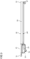
- FIG. 5 is a plan view of the upper tray 21, the lower tray 22, the nonconforming item tray 23, and the shared tray 24.
- the shared tray 24 is disposed forward of the upper tray 21 and the nonconforming item tray 23.
- the shared tray 24 is disposed forward of the lower tray 22 (see FIG. 3 ). A portion of the shared tray 24 is in straight alignment with the upper tray 21 and the lower tray 22 in a front-rear direction. Another portion of the shared tray 24 is in straight alignment with the nonconforming item tray 23 in the front-rear direction.
- a virtual line 51t in FIG. 5 indicates a movement path for the first end 51 of the electric wire 5.
- the upper tray 21 and the nonconforming item tray 23 are disposed under the movement path 51t for the first end 51.
- FIG. 6 is a front view of the rear portion of the collecting device 8 as viewed from the front to the rear.
- FIG. 7 is a partial rear view of the rear portion of the collecting device 8 as viewed from the rear to the front.
- the upper tray 21 is configured to be able to rotate around a rotation shaft 25 extending in the front-rear direction.
- the collecting device 8 includes a supporting arm 26 supporting the upper tray 21.
- the supporting arm 26 includes: a support 26a supporting the upper tray 21; and a connector 26b rotatably connected to a rod 27a of an air cylinder 27 through a connecting shaft 28.
- the rotation shaft 25 is disposed between the support 26a and the connector 26b.
- Extending the rod 27a of the air cylinder 27 rotates the supporting arm 26 around the rotation shaft 25 in the clockwise direction in FIG. 7 (i.e., in the counterclockwise direction in FIG. 6 ). This rotates the upper tray 21 downward (see the virtual line in FIG. 6 ).
- contracting the rod 27a of the air cylinder 27 rotates the supporting arm 26 around the rotation shaft 25 in the counterclockwise direction in FIG. 7 (i.e., in the clockwise direction in FIG. 6 ).
- This rotates the upper tray 21 upward see the solid line in FIG. 6 ).
- the mechanism just described, however, is presented by way of example only.
- the upper tray 21 may be rotated by any other mechanism.
- the actuator for rotating the upper tray 21 is not limited to the air cylinder 27.
- the lower tray 22 is disposed under the upper tray 21. Thus, upon rotation of the upper tray 21 as illustrated in FIG. 6 , a portion of the electric wire 5 adjacent to the first end 51, which has been collected into the upper tray 21, falls and is collected into the lower tray 22.
- the portion of the electric wire 5 adjacent to the first end 51 falls and is collected into the upper tray 21.
- the remaining portion of the electric wire 5 falls from a position on the conveyance belt 18 to the left (or specifically, a portion of the electric wire 5 close to the clamp 3R falls first, and then a portion of the electric wire 5 close to a second end 52 falls) and is collected into the shared tray 24.
- the shared tray 24 may be located higher or lower than the lower tray 22.
- the shared tray 24 is located at the same height as the lower tray 22.
- transferring the portion of the electric wire 5 adjacent to the first end 51 from the upper tray 21 to the lower tray 22 brings the electric wire 5 into a relatively straight state on the lower tray 22 and the shared tray 24.
- the nonconforming item tray 23 is disposed under the movement path 51t for the first end 51 of the electric wire 5 and laterally of the upper tray 21.
- the nonconforming item tray 23 is disposed leftward of the upper tray 21.
- the portion of the electric wire 5 adjacent to the first end 51 falls and is collected into the nonconforming item tray 23.
- the remaining portion of the electric wire 5 falls from a position on the conveyance belt 18 to the left and is collected into the shared tray 24.
- the nonconforming item tray 23 may be located at any height. In the present embodiment, the nonconforming item tray 23 is disposed higher than the shared tray 24.
- the longitudinal dimensions of the upper tray 21 and the nonconforming item tray 23 are each shorter than the longitudinal dimension of the shared tray 24.
- the breadth of the shared tray 24 i.e., the dimension of the shared tray 24 in the transverse direction in this embodiment
- the breadth of each of the upper tray 21 and the nonconforming item tray 23 is longer than the breadth of each of the upper tray 21 and the nonconforming item tray 23 (i.e., the dimension of each of the upper tray 21 and the nonconforming item tray 23 in the transverse direction in this embodiment).
- a partition wall 29 extending in an up-down direction and the front-rear direction is provided between the upper tray 21 and the nonconforming item tray 23.
- the upper edge of the partition wall 29 includes: an inclined portion 29a; a horizontal portion 29b located forward of the inclined portion 29a; and an inclined portion 29c located forward of the horizontal portion 29b.
- the inclined portion 29a inclines downward as it extends forward. In other words, the inclined portion 29a inclines downward as it extends toward the shared tray 24.
- the inclined portion 29c inclines upward as it extends forward. In other words, the inclined portion 29c inclines upward as it extends toward the shared tray 24.
- the conforming/nonconforming determiner 14 determines whether the electric wire 5 has been processed successfully. Upon determination that the electric wire 5 gripped by the clamp 3R is a conforming item, the controller 9 controls the clamp 3R such that the clamp 3R releases its grip on the electric wire 5, with the first end 51 of the electric wire 5 located over the upper tray 21. Upon determination that the electric wire 5 gripped by the clamp 3R is a nonconforming item, the controller 9 controls the clamp 3R such that the clamp 3R releases its grip on the electric wire 5, with the first end 51 of the electric wire 5 located over the nonconforming item tray 23.
- the clamp 3R may release its grip on the electric wire 5 during return of the first end 51 of the electric wire 5 from the position in front of the terminal crimper 4R to the position in front of the cutting edge 11.
- the clamp 3R may release its grip on the electric wire 5 during movement of the first end 51 toward the position in front of the terminal crimper 4R.
- the timing for the clamp 3R to release its grip on the electric wire 5 for collection may be any other timing.
- the electric wire processing apparatus 1 sequentially and continuously produces the electric wires 5 whose ends have the terminals 7 crimped thereto.
- the following description discusses how the electric wire processing apparatus 1 operates.
- the feeder 2 and the conveyance belt 18 feed the electric wire 5 forward (i.e., rightward in FIG. 1 ).
- the electric wire 5 is gripped by the clamps 3F and 3R and cut into electric wires 5 with the cutting edge 11 of the cutter device 10.
- the clamp 3F then turns rightward (i.e., upward in FIG. 1 ) while gripping the associated electric wire 5 that has been cut, thus guiding the front end of the associated electric wire 5 to the stripping edge 12F.
- the clamp 3R turns leftward (i.e., downward in FIG. 1 ) while gripping the associated electric wire 5, thus guiding the rear end of the associated electric wire 5 to the stripping edge 12R.
- the stripping edges 12F and 12R each strip the insulator 5b from the end of the associated electric wire 5.
- the clamp 3F then turns further rightward while gripping the associated electric wire 5, thus guiding the front end of the associated electric wire 5 to a position in front of the seal fitter 15F.
- the clamp 3R turns further leftward while gripping the associated electric wire 5, thus guiding the rear end of the associated electric wire 5 to a position in front of the seal fitter 15R.
- the seal fitters 15F and 15R each fit a waterproof seal to the end of the associated electric wire 5.
- the clamp 3F then turns further rightward while gripping the associated electric wire 5, thus guiding the front end of the associated electric wire 5 to a position in front of the terminal crimper 4F as indicated by the corresponding virtual line in FIG. 1 .
- the clamp 3R turns further leftward while gripping the associated electric wire 5, thus guiding the rear end of the associated electric wire 5 to a position in front of the terminal crimper 4R as indicated by the corresponding virtual line in FIG. 1 .
- the terminal crimpers 4F and 4R each crimp the terminal 7 to the end of the associated electric wire 5.
- the clamp 3F subsequently returns to its initial position facing the cutting edge 11 (i.e., the position indicated by the corresponding solid line in FIG. 1 ) while gripping the associated electric wire 5 having the terminal 7 crimped thereto, and releases its grip on the associated electric wire 5.
- the clamp 3R turns to its initial position, which faces the cutting edge 11, while gripping the associated electric wire 5.
- the clamp 3R releases its grip on (or releases) the associated electric wire 5 when the clamp 3R has reached a position over the upper tray 21.
- a portion of the conforming electric wire 5G adjacent to the first end 51 is collected into the upper tray 21 (see FIG. 4 ), and an entirety of the conforming electric wire 5G is thus collected partly into the upper tray 21 and partly into the shared tray 24 (see FIG. 5 ).
- the waterproof seals fitted to the electric wires 5G and 5N and the terminals crimped to the electric wires 5G and 5N are not illustrated.
- the clamp 3R Upon determination by the conforming/nonconforming determiner 14 that the associated electric wire 5 is a nonconforming item, the clamp 3R releases its grip on the associated electric wire 5 when the clamp 3R has reached a position over the nonconforming item tray 23. As a result, a portion of the nonconforming electric wire 5N adjacent to the first end 51 is collected into the nonconforming item tray 23 (see FIG. 4 ), and an entirety of the nonconforming electric wire 5N is thus collected partly into the nonconforming item tray 23 and partly into the shared tray 24 (see FIG. 5 ).
- the clamp 3R After having released the associated electric wire 5, the clamp 3R returns to the initial position.
- the electric wire processing apparatus 1 then repeats the operations described above.
- the electric wire processing apparatus 1 thus sequentially and continuously produces the electric wires 5 whose ends have the terminals 7 crimped thereto.
- the controller 9 drives the air cylinder 27 so as to rotate the upper tray 21 downward.
- the portion of each conforming electric wire 5G adjacent to the first end 51, which has been collected into the upper tray 21, falls and is transferred to the lower tray 22 (see FIG. 6 ).
- each conforming electric wire 5G is collected into the lower tray 22 and the shared tray 24.
- the controller 9 subsequently drives the air cylinder 27 so as to rotate the upper tray 21 upward.
- the upper tray 21 then collects the portion of each conforming electric wire 5G adjacent to the first end 51 again.
- the portion of the conforming electric wire 5G adjacent to the first end 51 is collected into the lower tray 22, and the portion of the nonconforming electric wire 5N adjacent to the first end 51 is collected into the nonconforming item tray 23.
- This enables a user to make a clear distinction between the conforming electric wire 5G and the nonconforming electric wire 5N.
- the user is thus able to remove the conforming electric wire 5G from the lower tray 22 and the shared tray 24 without making any mistake.
- the user is also able to remove the nonconforming electric wire 5N from the nonconforming item tray 23 and the shared tray 24 without making any mistake. Accordingly, the user is able to appropriately sort the electric wires 5 into the conforming and nonconforming electric wires 5G and 5N.
- the electric wire processing apparatus 1 collects the portion of the conforming electric wire 5G (hereinafter simply referred to as a "conforming item 5G") adjacent to the first end 51 into the upper tray 21, and collects the portion of the nonconforming electric wire 5N (hereinafter simply referred to as a "nonconforming item 5N") adjacent to the first end 51 into the nonconforming item tray 23.
- the electric wire processing apparatus 1 thus sorts the portion of the conforming item 5G adjacent to the first end 51 from the portion of the nonconforming item 5N adjacent to the first end 51. Because each of the conforming and nonconforming items 5G and 5N is the electric wire 5 that is long, the electric wire processing apparatus 1 does not necessarily have to sort an entirety of each item.
- the electric wire processing apparatus 1 is able to make a clear distinction between the conforming and nonconforming items 5G and 5N as a whole by accurately sorting a portion of each item adjacent to the first end 51 (see FIGS. 4 and 5 ). Consequently, the electric wire processing apparatus 1 is able to appropriately sort the conforming item 5G from the nonconforming item 5N.
- the electric wire processing apparatus 1 collects the remaining portion of each of the conforming and nonconforming items 5G and 5N into the shared tray 24. Portions of the conforming and nonconforming items 5G and 5N adjacent to the second ends 52 are all collected into the same tray (i.e., the shared tray 24). Thus, unlike the case where an entirety of each conforming electric wire 5G and an entirety of each nonconforming electric wire 5N are separately collected into different trays, each second end 52 will not be collected into a wrong tray. The portion of each item adjacent to the second end 52 will not run onto a region between two trays.
- the electric wire processing apparatus 1 reduces the possibility that the portion of the conforming electric wire 5G adjacent to the first end 51 will be pulled toward the second end 52 and transferred from the upper tray 21 to the nonconforming item tray 23.
- the electric wire processing apparatus 1 also reduces the possibility that the portion of the nonconforming electric wire 5N adjacent to the first end 51 will be pulled toward the second end 52 and transferred from the nonconforming item tray 23 to the upper tray 21. Consequently, the electric wire processing apparatus 1 is able to correctly collect the portion of each conforming item 5G adjacent to the first end 51 into the upper tray 21 and correctly collect the portion of each nonconforming item 5N adjacent to the first end 51 into the nonconforming item tray 23.
- the electric wire processing apparatus 1 is able to collect the conforming and nonconforming items 5G and 5N such that the portion of the conforming item 5G adjacent to the first end 51 is correctly sorted from the portion of the nonconforming item 5N adjacent to the first end 51, and is thus able to appropriately sort the conforming item 5G from the nonconforming item 5N.
- the partition wall 29 extending in the up-down direction serves as a partition between the upper tray 21 and the nonconforming item tray 23 as illustrated in FIG. 4 .
- the electric wire processing apparatus 1 is thus able to accurately sort, with the partition wall 29, the portion of the conforming item 5G adjacent to the first end 51 from the portion of the nonconforming item 5N adjacent to the first end 51.
- the upper edge of the partition wall 29 includes the inclined portion 29a that inclines downward as it extends toward the shared tray 24 (i.e., forward).
- the electric wire 5 is long and may thus sway when the portion of the electric wire 5 adjacent to the first end 51 falls upon being released from the clamp 3R.
- a portion 51a of the conforming item 5G adjacent to the first end 51 may bend and fall on the inclined portion 29a of the upper edge of the partition wall 29 as illustrated in, for example, FIG. 8 . If the portion 51a of the conforming item 5G has fallen on the inclined portion 29a, however, the portion 51a would then slide down along the inclination of the inclined portion 29a (see the arrow in FIG. 8 ).
- the portion of the conforming item 5G adjacent to the first end 51 will be collected into the upper tray 21.
- the nonconforming item 5N If a bent portion of the nonconforming item 5N has fallen on the inclined portion 29a of the partition wall 29, the bent portion would slide down along the inclined portion 29a and would thus be collected into the nonconforming item tray 23. Accordingly, if the portion of the electric wire 5 adjacent to the first end 51 sways when the clamp 3R releases its grip on the electric wire 5, the portion of the conforming item 5G adjacent to the first end 51 would be successfully collected into the upper tray 21, and the portion of the nonconforming item 5N adjacent to the first end 51 would be successfully collected into the nonconforming item tray 23.
- the upper tray 21 is configured to allow the portion of the conforming item 5G adjacent to the first end 51, which has been collected, to fall.
- the lower tray 22 to receive the portion of the conforming item 5G adjacent to the first end 51, which has fallen, is disposed under the upper tray 21.
- the portion of the conforming item 5G adjacent to the first end 51, which has been collected into the upper tray 21, is thus transferable to the lower tray 22.
- the user While removing the conforming item 5G from the lower tray 22 and the shared tray 24, the user is able to collect the portion of another conforming item 5G adjacent to the first end 51 into the upper tray 21. Accordingly, the user does not have to deactivate the electric wire processing apparatus 1 in order to remove the conforming item 5G. Consequently, the electric wire processing apparatus 1 is able to achieve higher processing efficiency.
- the clamp 3R which grips the electric wire 5 during processing of the first end 51 of the electric wire 5, causes the portion of the electric wire 5 adjacent to the first end 51 to be collected into the upper tray 21 or the nonconforming item tray 23.
- the present embodiment thus eliminates the need to pass the portion of the electric wire 5 adjacent to the first end 51 between multiple clamps when the first end 51 of the electric wire 5 is processed and is then collected into the upper tray 21 or the nonconforming item tray 23.
- the portion of the electric wire 5 adjacent to the first end 51 does not have to be passed from one clamp to another clamp. This results in an increase in electric wire processing efficiency and a reduction in takt time.
- the user may run a test operation to check whether the electric wire processing apparatus 1 operates successfully.
- An electric wire provided as a result of such a test operation (which will hereinafter be referred to as an "adjustment wire") is preferably collected into either the upper tray 21 or the nonconforming item tray 23.
- the user is able to remove the collected adjustment wire from the upper tray 21 or the nonconforming item tray 23 so as to make, for example, a visual check of the adjustment wire, thus determining whether the adjustment wire is conforming or nonconforming.
- the adjustment wire may be collected into the nonconforming item tray 23 when a distinction is to be made between the adjustment wire and the conforming item 5G provided as a result of the actual operation. Accordingly, the electric wire processing apparatus 1 would be able to prevent mixing of the adjustment wire and the conforming item 5G if the user has started the actual operation without removing the adjustment wire after the test operation.
- the clamp 3R grips the electric wire 5 during processing of the first end 51 of the electric wire 5 and then causes the portion of the electric wire 5 adjacent to the first end 51 to be collected into the upper tray 21 or the nonconforming item tray 23.
- one clamp may grip the electric wire 5, and another clamp may cause the portion of the electric wire 5 adjacent to the first end 51 to be collected.
- a first clamp may pass the portion of the electric wire 5 adjacent to the first end 51 to a second clamp, and then the second clamp may cause the portion to be collected into the upper tray 21 or the nonconforming item tray 23.
- the second clamp corresponds to the clamp according to the present invention.
- Such an embodiment allows the first clamp to return to its initial position located in front of the cutter device 10 (i.e., the position indicated by the associated solid line in FIG. 1 ) while the second clamp causes the electric wire 5 to be collected into the upper tray 21 or the nonconforming item tray 23.
- the first clamp enables the start of processing of another electric wire 5 while the second clamp causes the processed electric wire 5 to be collected into the upper tray 21 or the nonconforming item tray 23. This allows the collection and processing of the electric wires 5 to proceed concurrently.
- the electric wire processing apparatus 1 may include a cutter. Upon determination by the conforming/nonconforming determiner 14 that the electric wire 5 is nonconforming, the cutter cuts off the first end 51 from the nonconforming item 5N before the nonconforming item 5N is collected into the nonconforming item tray 23. In this case, the nonconforming item 5N from which the first end 51 has been cut off will be collected into the nonconforming item tray 23. The user is thus able to differentiate at a glance between the nonconforming item 5N from which the first end 51 has been cut off and the conforming item 5G including the first end 51. Accordingly, the user is able to easily distinguish the conforming item 5G from the nonconforming item 5N.
- the upper tray 21 is configured to rotate upward and downward.
- the upper tray 21, from which the electric wire 5 is allowed to fall, does not necessarily have to be of a rotary type.
- the upper tray 21 may be of a sliding type.
- the upper tray 21 is not limited to any particular mechanism.
- the upper tray 21 is configured to allow the electric wire 5 to fall therefrom, and the lower tray 22 is disposed under the upper tray 21.
- the upper tray 21 and the lower tray 22, however, are not limited to any particular configuration or location.
- the upper tray 21 may be configured such that the electric wire 5 is unable to fall therefrom, and the lower tray 22 may be optional.
- the upper tray 21 may be optional, and the electric wire processing apparatus 1 may be configured such that the portion of the conforming item 5G adjacent to the first end 51 is directly collected into the lower tray 22.
- the clamp 3R to grip the portion of the electric wire 5 adjacent to the first end 51 is configured to turn around the turning center CR.
- the direction of movement of the clamp 3R is not limited to a turning direction.
- the clamp 3R may be configured to move in a straight line.
- the longitudinal dimensions of the upper tray 21, the lower tray 22, and the nonconforming item tray 23 are each shorter than the longitudinal dimension of the shared tray 24.
- the upper tray 21, the lower tray 22, and the nonconforming item tray 23 may each have any longitudinal dimension.
- the longitudinal dimension of at least one of the upper tray 21, the lower tray 22, and the nonconforming item tray 23 may be equal to or longer than the longitudinal dimension of the shared tray 24.
- the subsequent processes may be performed as follows. First, the clamps 3F and 3R return to the initial positions (i.e., the positions indicated by the associated solid lines in FIG. 1 ), and then the feeder 2 feeds the electric wire 5 forward to such an extent that the clamp 3R is able to grip the electric wire 5. The clamps 3F and 3R grip the electric wire 5, and the electric wire 5 is cut with the cutting edge 11.
- the electric wire 5 is thus separated into an electric wire 5 gripped by the clamp 3F and a short electric wire 5 gripped by the clamp 3R.
- the clamp 3R subsequently turns and releases its grip on the short electric wire 5 over the nonconforming item tray 23.
- the short electric wire 5 that has been determined to be a nonconforming item is collected into the nonconforming item tray 23.
- the upper tray 21 and the lower tray 22 serve as an example of a conforming item collector to collect a portion of the conforming item 5G adjacent to the first end 51
- the nonconforming item tray 23 serves as an example of a nonconforming item collector to collect a portion of the nonconforming item 5N adjacent to the first end 51
- the shared tray 24 serves as an example of a shared collector to collect the remaining portions of the conforming and nonconforming items 5G and 5N.
- the shape of each of the conforming item collector, the nonconforming item collector, and the shared collector does not necessarily have to be a box shape with a bottom wall and lateral walls.
- the collectors may each have any other shape.
- the present invention is particularly effective in processing the electric wire 5 that is long.
- the present invention is also naturally applicable to the electric wire 5 that is short.
- the electric wire processing apparatus according to the present invention may process both of long and short electric wires.
Landscapes
- Engineering & Computer Science (AREA)
- Manufacturing & Machinery (AREA)
- Mechanical Engineering (AREA)
- Manufacturing Of Electrical Connectors (AREA)
- Indicating Or Recording The Presence, Absence, Or Direction Of Movement (AREA)
- Transmission And Conversion Of Sensor Element Output (AREA)
Description
- The present invention relates to electric wire processing apparatuses.
- Electric wire processing apparatuses to perform various processes on electric wires are known in the related art. For example, a known electric wire processing apparatus performs a process, such as cutting, insulator stripping, seal fitting, or terminal crimping, on electric wires each including a core and an insulator surrounding the core. Another known electric wire processing apparatus is configured to detect whether electric wires have been processed properly and collect the electric wires such that the electric wires are sorted into conforming and nonconforming items.
-
JP 2011-210460 A JP 2011-210460 A
Patent Literature 2 provides a further electric wire processing apparatus according to the prior art. -
- [Patent Literature 1]
JP 2011-210460 A - [Patent Literature 2]
WO 2013183120 A1 - When an electric wire is long, however, conveying a first end of the electric wire by turning of the clamp makes a second end of the electric wire less movable than the first end of the electric wire; thus, it is not necessarily easy to collect an entirety of the electric wire into the product tray or the nonconforming item tray with accuracy. For example, when a nonconforming item is to be collected into the nonconforming item tray, a first end of the nonconforming item may be collected into the nonconforming item tray, but a second end of the nonconforming item may unfortunately be collected into the product tray by mistake. In this case, the nonconforming item may temporarily run onto a boundary region between the nonconforming item tray and the product tray while being collected into the nonconforming item tray, and then the first end may be pulled toward the second end and transferred from the nonconforming item tray to the product tray. As a result, the nonconforming item may be collected into the product tray by mistake. The above-described apparatus may thus fail to appropriately sort a long electric wire into a conforming or nonconforming item.
- The present invention has been made in view of the above points, and its object is to provide an electric wire processing apparatus that would be able to collect an electric wire such that the electric wire is appropriately sorted into a conforming or nonconforming item if the electric wire is long.
- An electric wire processing apparatus disclosed herein includes: a processor to perform a predetermined process on an electric wire including a first end and a second end; a conforming/nonconforming determiner to determine whether the process has been performed successfully; a clamp to grip a portion of the electric wire adjacent to the first end, the clamp being movable so as to convey the first end of the electric wire; a conforming item collector disposed under a movement path for the first end of the electric wire that is being conveyed by the clamp, the conforming item collector being configured to collect a first end side portion of the electric wire determined to be a conforming item by the conforming/nonconforming determiner; a nonconforming item collector disposed under the movement path for the first end of the electric wire that is being conveyed by the clamp, the nonconforming item collector being configured to collect a first end side portion of the electric wire determined to be a nonconforming item by the conforming/nonconforming determiner; a shared collector disposed toward the second end of the electric wire relative to the conforming item collector and the nonconforming item collector, the shared collector being configured to collect a remaining portion of the electric wire determined to be a conforming item by the conforming/nonconforming determiner and a remaining portion of the electric wire determined to be a nonconforming item by the conforming/nonconforming determiner; and a clamp controller to cause, upon determination by the conforming/nonconforming determiner that the electric wire is a conforming item, the clamp to release its grip on the first end of the electric wire when the first end is located over the conforming item collector, and to cause, upon determination by the conforming/nonconforming determiner that the electric wire is a nonconforming item, the clamp to release its grip on the first end of the electric wire when the first end is located over the nonconforming item collector. As used herein, the term "portion of the electric wire adjacent to the first end" refers to a portion of the electric wire located toward the first end relative to the longitudinal center of the electric wire.
- The electric wire processing apparatus described above causes the portion of the electric wire adjacent to the first end to be gripped by the clamp and conveyed in accordance with movement of the clamp. The first end side portion of the electric wire determined to be conforming by the conforming/nonconforming determiner (hereinafter simply referred to as a "conforming item") is collected into the conforming item collector. The first end side portion of the electric wire determined to be nonconforming by the conforming/nonconforming determiner (hereinafter simply referred to as a "nonconforming item") is collected into the nonconforming item collector. The conforming and nonconforming items are collected such that the first end side portion of the conforming item and the first end side portion of the nonconforming item are accurately sorted from each other. The remaining portion of the conforming item and the remaining portion of the nonconforming item are both collected into the shared collector. The electric wire processing apparatus thus eliminates the possibility of collecting the portion of the electric wire adjacent to the second end into a wrong place. Accordingly, the electric wire processing apparatus reduces the possibility that the portion of the conforming item adjacent to the first end will be pulled toward the second end and transferred from the conforming item collector to the nonconforming item collector. The electric wire processing apparatus also reduces the possibility that the portion of the nonconforming item adjacent to the first end will be pulled toward the second end and transferred from the nonconforming item collector to the conforming item collector. When the electric wire is long, the electric wire processing apparatus does not necessarily have to sort an entirety of the electric wire. The electric wire processing apparatus is able to make a clear distinction between the conforming and nonconforming items as a whole by sorting a portion of the electric wire. The electric wire processing apparatus accurately sorts the first end side portion of the conforming item from the first end side portion of the nonconforming item and is thus able to make a clear distinction between the conforming and nonconforming items as a whole. Consequently, the electric wire processing apparatus is able to appropriately sort the conforming item from the nonconforming item.
- In a preferred embodiment, the processor is configured to perform the predetermined process on the first end of the electric wire gripped by the clamp.
- The clamp may receive the processed electric wire from another clamp that grips the electric wire during processing of the electric wire by the processor. In the above embodiment, the clamp grips the electric wire during processing of the electric wire by the processor. The above embodiment thus eliminates the need to pass the electric wire between the clamps or reduces the number of times the electric wire is to be passed between the clamps, resulting in increased electric wire processing efficiency.
- In a preferred embodiment, the electric wire processing apparatus includes a partition wall disposed between the conforming item collector and the nonconforming item collector and extending in an up-down direction.
- In the above embodiment, the first end side portion of the conforming item is accurately sorted from the first end side portion of the nonconforming item with the partition wall.
- In a preferred embodiment, an upper edge of the partition wall includes an inclined portion that inclines downward as it extends toward the shared collector.
- The electric wire that is long may sway when the electric wire falls upon being released from the clamp. In such a case, the portion of the electric wire adjacent to the first end may bend and fall on the upper edge of the partition wall. In the above embodiment, however, the upper edge of the partition wall includes the inclined portion. Thus, when the portion of the electric wire adjacent to the first end has fallen on the inclined portion, the portion then slides down along the inclination of the inclined portion. Accordingly, the electric wire processing apparatus is able to successfully collect the first end side portion of the electric wire into the conforming item collector or the nonconforming item collector.
- In a preferred embodiment, the conforming item collector includes: an upper collector to collect the first end side portion of the electric wire and allow the collected portion of the electric wire to fall; and a lower collector disposed under the upper collector, the lower collector being configured to collect the portion of the electric wire that has fallen from the upper collector.
- In the above embodiment, the first end side portion of the conforming item that has been collected into the upper collector is transferrable to the lower collector. Accordingly, during removal of the conforming item from the lower collector and the shared collector, the electric wire processing apparatus is able to collect the first end side portion of another conforming item into the upper collector. Consequently, the electric wire processing apparatus enables collection of one conforming item and removal of another conforming item to be carried out simultaneously, resulting in an increase in the efficiency of electric wire sorting operation.
- The electric wire is not limited to any particular type of electric wire. The process to be performed on the electric wire is not limited to any particular process. The electric wire may include: a core made of a conductor; and an insulator surrounding the core. The processor may include at least one of: a device to cut the electric wire so as to provide the first end; a device to strip the insulator from the first end of the electric wire; a device to fit a seal to the first end of the electric wire; and a device to crimp a terminal to the first end of the electric wire.
- Although the direction of movement of the clamp is not limited to any particular direction, the above-described effects will be particularly pronounced when the clamp is configured to turn around a vertical line.
- The present invention provides an electric wire processing apparatus that would be able to collect an electric wire such that the electric wire is appropriately sorted into a conforming or nonconforming item if the electric wire is long.
-
-
FIG. 1 is a plan view schematically illustrating the arrangement of an electric wire processing apparatus according to one embodiment. -
FIG. 2 is a perspective view schematically illustrating an electric wire. -
FIG. 3 is a perspective view of a collecting device. -
FIG. 4 is a perspective view of the rear portion of the collecting device. -
FIG. 5 is a plan view of an upper tray, a nonconforming item tray, and a shared tray of the collecting device. -
FIG. 6 is a front view of the rear portion of the collecting device. -
FIG. 7 is a partial rear view of the rear portion of the collecting device. -
FIG. 8 is a perspective view of the rear portion of the collecting device, illustrating a first end side portion of an electric wire that has fallen on the upper edge of a partition wall. - An embodiment of the present invention will now be described.
FIG. 1 is a plan view schematically illustrating the arrangement of an electric wire processing apparatus 1 according to the present embodiment. In the following description, the right and left sides inFIG. 1 are defined as the front and rear sides, respectively, and the upper and lower sides inFIG. 1 are defined as the right and left sides, respectively. These directions, however, are defined merely for the sake of convenience of description and do not limit, for example, where the electric wire processing apparatus 1 may be installed. - As illustrated in
FIG. 2 , anelectric wire 5 is a "coated electric wire". Theelectric wire 5 includes: acore 5a made of a conductor, such as metal; and aninsulator 5b made of a resin or other material surrounding thecore 5a. - As illustrated in
FIG. 1 , the electric wire processing apparatus 1 includes: straighteningrollers 6 to smooth the curves of theelectric wire 5; afeeder 2 to feed theelectric wire 5; clamps 3F and 3R to grip theelectric wire 5; aconveyance belt 18 to convey theelectric wire 5 forward; acutter device 10;seal fitters electric wire 5;terminal crimpers terminals 7 to theelectric wire 5; acollecting device 8 to collect theelectric wire 5 that has been processed; and acontroller 9. - The
feeder 2 is not limited to any particular arrangement. In this embodiment, thefeeder 2 includes: a pair of right front and right rear pulleys 2A; aright conveyance belt 2B wound around the right front and right rear pulleys 2A; a pair of left front and leftrear pulleys 2A; and aleft conveyance belt 2B wound around the left front and leftrear pulleys 2A. Although not illustrated, at least one of thepulleys 2A is connected with a motor. Driving the motor rotates thepulleys 2A, causing theconveyance belts 2B to circulate. Theelectric wire 5 sandwiched between the right and leftconveyance belts 2B is thus fed forward. - The
cutter device 10 includes: a cuttingedge 11 to cut theelectric wire 5; and strippingedges insulator 5b from theelectric wire 5. The strippingedge 12F, thecutting edge 11, and the strippingedge 12R are disposed side by side in a transverse direction. - The electric wire processing apparatus 1 is able to perform the processes of: cutting the
electric wire 5; stripping theinsulator 5b from theelectric wire 5; fitting waterproof seals to theelectric wire 5; and crimping theterminals 7 to the ends of theelectric wire 5. Thecutting edge 11 is an example of a processor to cut theelectric wire 5. The strippingedges insulator 5b from theelectric wire 5. Theseal fitters electric wire 5. Theterminal crimpers terminal 7 to the end of theelectric wire 5. The electric wire processing apparatus 1 does not necessarily have to perform all of the processes just mentioned. The electric wire processing apparatus includes a device to perform at least one of the processes. - The
conveyance belt 18 is disposed forward of thecutter device 10. Theconveyance belt 18 is configured to feed theelectric wire 5 forward in conjunction with thefeeder 2. Specifically, theconveyance belt 18 is configured to run forward when thefeeder 2 feeds theelectric wire 5 forward. A portion of theelectric wire 5 is placed on theconveyance belt 18 and conveyed forward with the running of theconveyance belt 18. - The
clamps feeder 2. Theclamps electric wire 5 fed from thefeeder 2. Theclamps electric wire 5 and release its grip on theelectric wire 5. - The
clamp 3F is disposed rearward of thecutter device 10. Theclamp 3R is disposed forward of thecutter device 10. Theclamp 3F is configured to be able to turn around a turning center CF. Theclamp 3R is configured to be able to turn around a turning center CR. Each of the turning centers CF and CR is a vertical line that extends vertically. Although not illustrated, the electric wire processing apparatus 1 includes: an actuator to open and close theclamp 3F (i.e., an actuator to cause theclamp 3F to grip theelectric wire 5 and release its grip on the electric wire 5); an actuator to cause theclamp 3F to turn; an actuator to open and close theclamp 3R; and an actuator to cause theclamp 3R to turn. Such actuators are well known and will thus not be described any further. Theclamp 3F turns while gripping the front end of the rear sideelectric wire 5 that has been cut, thus conveying the front end of theelectric wire 5 to the strippingedge 12F, the seal fitter 15F, and theterminal crimper 4F. Theclamp 3R turns while gripping the rear end of the front sideelectric wire 5 that has been cut, thus conveying the rear end of theelectric wire 5 to the strippingedge 12R, the seal fitter 15R, and theterminal crimper 4R. - The electric wire processing apparatus 1 includes a conforming/
nonconforming determiner 14 to determine whether theelectric wire 5 has been processed successfully. In the present embodiment, the conforming/nonconforming determiner 14 is configured to determine whether theelectric wire 5 has been cut successfully, whether theelectric wire 5 has been stripped of theinsulator 5b successfully, whether a waterproof seal has been fitted to theelectric wire 5 successfully, and whether a terminal has been crimped to theelectric wire 5 successfully. The conforming/nonconforming determiner 14 does not necessarily have to make determinations on whether all of the cutting, stripping, waterproof seal fitting, and terminal crimping processes have been performed successfully but may be configured to make a determination on at least one of the processes. Such a determiner is well known and will thus not be described in detail. - The collecting
device 8 will now be described. The collectingdevice 8 collects theelectric wire 5 that has been processed.FIG. 3 is a perspective view of thecollecting device 8.FIG. 4 is an enlarged perspective view of the rear portion of thecollecting device 8. - As illustrated in
FIG. 4 , the collectingdevice 8 includes: anupper tray 21; alower tray 22 disposed under theupper tray 21; and anonconforming item tray 23 disposed laterally of the upper tray 21 (i.e., leftward of theupper tray 21 in the present embodiment). As illustrated inFIG. 3 , the collectingdevice 8 further includes a sharedtray 24. Theupper tray 21, thelower tray 22, thenonconforming item tray 23, and the sharedtray 24 are disposed laterally of the conveyance belt 18 (i.e., leftward of theconveyance belt 18 in the present embodiment).FIG. 5 is a plan view of theupper tray 21, thelower tray 22, thenonconforming item tray 23, and the sharedtray 24. The sharedtray 24 is disposed forward of theupper tray 21 and thenonconforming item tray 23. The sharedtray 24 is disposed forward of the lower tray 22 (seeFIG. 3 ). A portion of the sharedtray 24 is in straight alignment with theupper tray 21 and thelower tray 22 in a front-rear direction. Another portion of the sharedtray 24 is in straight alignment with thenonconforming item tray 23 in the front-rear direction. - As illustrated in
FIG. 1 , turning of theclamp 3R around the turning center CR causes arear end 51 of theelectric wire 5 gripped by theclamp 3R to move between a position in front of thecutting edge 11 and a position in front of theterminal crimper 4R. The rear end of the front sideelectric wire 5 that has been cut will hereinafter be referred to as a "first end". The front end of the front sideelectric wire 5 that has been cut will hereinafter be referred to as a "second end". Avirtual line 51t inFIG. 5 indicates a movement path for thefirst end 51 of theelectric wire 5. As illustrated inFIG. 5 , theupper tray 21 and thenonconforming item tray 23 are disposed under themovement path 51t for thefirst end 51. -
FIG. 6 is a front view of the rear portion of thecollecting device 8 as viewed from the front to the rear.FIG. 7 is a partial rear view of the rear portion of thecollecting device 8 as viewed from the rear to the front. As illustrated inFIG. 6 , theupper tray 21 is configured to be able to rotate around arotation shaft 25 extending in the front-rear direction. Specifically, as illustrated inFIG. 7 , the collectingdevice 8 includes a supportingarm 26 supporting theupper tray 21. The supportingarm 26 includes: asupport 26a supporting theupper tray 21; and aconnector 26b rotatably connected to a rod 27a of anair cylinder 27 through a connectingshaft 28. Therotation shaft 25 is disposed between thesupport 26a and theconnector 26b. Extending the rod 27a of theair cylinder 27 rotates the supportingarm 26 around therotation shaft 25 in the clockwise direction inFIG. 7 (i.e., in the counterclockwise direction inFIG. 6 ). This rotates theupper tray 21 downward (see the virtual line inFIG. 6 ). In contrast, contracting the rod 27a of theair cylinder 27 rotates the supportingarm 26 around therotation shaft 25 in the counterclockwise direction inFIG. 7 (i.e., in the clockwise direction inFIG. 6 ). This rotates theupper tray 21 upward (see the solid line inFIG. 6 ). The mechanism just described, however, is presented by way of example only. Theupper tray 21 may be rotated by any other mechanism. The actuator for rotating theupper tray 21 is not limited to theair cylinder 27. - The
lower tray 22 is disposed under theupper tray 21. Thus, upon rotation of theupper tray 21 as illustrated inFIG. 6 , a portion of theelectric wire 5 adjacent to thefirst end 51, which has been collected into theupper tray 21, falls and is collected into thelower tray 22. - Upon release of the
electric wire 5 from theclamp 3R, with thefirst end 51 of theelectric wire 5 located over theupper tray 21, the portion of theelectric wire 5 adjacent to thefirst end 51 falls and is collected into theupper tray 21. During turning of theclamp 3R from the position in front of thecutter device 10 to the position in front of theterminal crimper 4R, the remaining portion of theelectric wire 5 falls from a position on theconveyance belt 18 to the left (or specifically, a portion of theelectric wire 5 close to theclamp 3R falls first, and then a portion of theelectric wire 5 close to asecond end 52 falls) and is collected into the sharedtray 24. The sharedtray 24 may be located higher or lower than thelower tray 22. In the present embodiment, the sharedtray 24 is located at the same height as thelower tray 22. Thus, transferring the portion of theelectric wire 5 adjacent to thefirst end 51 from theupper tray 21 to thelower tray 22 brings theelectric wire 5 into a relatively straight state on thelower tray 22 and the sharedtray 24. - As previously mentioned, the
nonconforming item tray 23 is disposed under themovement path 51t for thefirst end 51 of theelectric wire 5 and laterally of theupper tray 21. In the present embodiment, thenonconforming item tray 23 is disposed leftward of theupper tray 21. Upon release of theelectric wire 5 from theclamp 3R, with thefirst end 51 of theelectric wire 5 located over thenonconforming item tray 23, the portion of theelectric wire 5 adjacent to thefirst end 51 falls and is collected into thenonconforming item tray 23. During turning of theclamp 3R from the position in front of thecutter device 10 to the position in front of theterminal crimper 4R, the remaining portion of theelectric wire 5 falls from a position on theconveyance belt 18 to the left and is collected into the sharedtray 24. Thenonconforming item tray 23 may be located at any height. In the present embodiment, thenonconforming item tray 23 is disposed higher than the sharedtray 24. - As illustrated in
FIG. 5 , the longitudinal dimensions of theupper tray 21 and the nonconforming item tray 23 (i.e., the dimensions of theupper tray 21 and thenonconforming item tray 23 in the front-rear direction in this embodiment) are each shorter than the longitudinal dimension of the sharedtray 24. The breadth of the shared tray 24 (i.e., the dimension of the sharedtray 24 in the transverse direction in this embodiment) is longer than the breadth of each of theupper tray 21 and the nonconforming item tray 23 (i.e., the dimension of each of theupper tray 21 and thenonconforming item tray 23 in the transverse direction in this embodiment). - As illustrated in
FIG. 4 , apartition wall 29 extending in an up-down direction and the front-rear direction is provided between theupper tray 21 and thenonconforming item tray 23. The upper edge of thepartition wall 29 includes: aninclined portion 29a; ahorizontal portion 29b located forward of theinclined portion 29a; and aninclined portion 29c located forward of thehorizontal portion 29b. Theinclined portion 29a inclines downward as it extends forward. In other words, theinclined portion 29a inclines downward as it extends toward the sharedtray 24. Theinclined portion 29c inclines upward as it extends forward. In other words, theinclined portion 29c inclines upward as it extends toward the sharedtray 24. - As previously described, the conforming/
nonconforming determiner 14 determines whether theelectric wire 5 has been processed successfully. Upon determination that theelectric wire 5 gripped by theclamp 3R is a conforming item, thecontroller 9 controls theclamp 3R such that theclamp 3R releases its grip on theelectric wire 5, with thefirst end 51 of theelectric wire 5 located over theupper tray 21. Upon determination that theelectric wire 5 gripped by theclamp 3R is a nonconforming item, thecontroller 9 controls theclamp 3R such that theclamp 3R releases its grip on theelectric wire 5, with thefirst end 51 of theelectric wire 5 located over thenonconforming item tray 23. Theclamp 3R may release its grip on theelectric wire 5 during return of thefirst end 51 of theelectric wire 5 from the position in front of theterminal crimper 4R to the position in front of thecutting edge 11. Upon determination that the process of cutting theelectric wire 5, stripping off theinsulator 5b, or fitting a waterproof seal has been performed unsuccessfully before terminal crimping, theclamp 3R may release its grip on theelectric wire 5 during movement of thefirst end 51 toward the position in front of theterminal crimper 4R. The timing for theclamp 3R to release its grip on theelectric wire 5 for collection may be any other timing. - The electric wire processing apparatus 1 sequentially and continuously produces the
electric wires 5 whose ends have theterminals 7 crimped thereto. The following description discusses how the electric wire processing apparatus 1 operates. First, thefeeder 2 and theconveyance belt 18 feed theelectric wire 5 forward (i.e., rightward inFIG. 1 ). Theelectric wire 5 is gripped by theclamps electric wires 5 with thecutting edge 11 of thecutter device 10. - The
clamp 3F then turns rightward (i.e., upward inFIG. 1 ) while gripping the associatedelectric wire 5 that has been cut, thus guiding the front end of the associatedelectric wire 5 to the strippingedge 12F. Theclamp 3R turns leftward (i.e., downward inFIG. 1 ) while gripping the associatedelectric wire 5, thus guiding the rear end of the associatedelectric wire 5 to the strippingedge 12R. The strippingedges insulator 5b from the end of the associatedelectric wire 5. - The
clamp 3F then turns further rightward while gripping the associatedelectric wire 5, thus guiding the front end of the associatedelectric wire 5 to a position in front of the seal fitter 15F. Theclamp 3R turns further leftward while gripping the associatedelectric wire 5, thus guiding the rear end of the associatedelectric wire 5 to a position in front of the seal fitter 15R. Theseal fitters electric wire 5. - The
clamp 3F then turns further rightward while gripping the associatedelectric wire 5, thus guiding the front end of the associatedelectric wire 5 to a position in front of theterminal crimper 4F as indicated by the corresponding virtual line inFIG. 1 . Theclamp 3R turns further leftward while gripping the associatedelectric wire 5, thus guiding the rear end of the associatedelectric wire 5 to a position in front of theterminal crimper 4R as indicated by the corresponding virtual line inFIG. 1 . Theterminal crimpers terminal 7 to the end of the associatedelectric wire 5. - The
clamp 3F subsequently returns to its initial position facing the cutting edge 11 (i.e., the position indicated by the corresponding solid line inFIG. 1 ) while gripping the associatedelectric wire 5 having the terminal 7 crimped thereto, and releases its grip on the associatedelectric wire 5. - The
clamp 3R turns to its initial position, which faces thecutting edge 11, while gripping the associatedelectric wire 5. Upon determination by the conforming/nonconforming determiner 14 that the associatedelectric wire 5 is a conforming item, theclamp 3R releases its grip on (or releases) the associatedelectric wire 5 when theclamp 3R has reached a position over theupper tray 21. As a result, a portion of the conformingelectric wire 5G adjacent to thefirst end 51 is collected into the upper tray 21 (seeFIG. 4 ), and an entirety of the conformingelectric wire 5G is thus collected partly into theupper tray 21 and partly into the shared tray 24 (seeFIG. 5 ). InFIGS. 4 and5 , the waterproof seals fitted to theelectric wires electric wires - Upon determination by the conforming/
nonconforming determiner 14 that the associatedelectric wire 5 is a nonconforming item, theclamp 3R releases its grip on the associatedelectric wire 5 when theclamp 3R has reached a position over thenonconforming item tray 23. As a result, a portion of the nonconformingelectric wire 5N adjacent to thefirst end 51 is collected into the nonconforming item tray 23 (seeFIG. 4 ), and an entirety of the nonconformingelectric wire 5N is thus collected partly into thenonconforming item tray 23 and partly into the shared tray 24 (seeFIG. 5 ). - After having released the associated
electric wire 5, theclamp 3R returns to the initial position. The electric wire processing apparatus 1 then repeats the operations described above. The electric wire processing apparatus 1 thus sequentially and continuously produces theelectric wires 5 whose ends have theterminals 7 crimped thereto. - After a predetermined number of the
electric wires 5 have been processed, thecontroller 9 drives theair cylinder 27 so as to rotate theupper tray 21 downward. Thus, the portion of each conformingelectric wire 5G adjacent to thefirst end 51, which has been collected into theupper tray 21, falls and is transferred to the lower tray 22 (seeFIG. 6 ). As a result, each conformingelectric wire 5G is collected into thelower tray 22 and the sharedtray 24. Thecontroller 9 subsequently drives theair cylinder 27 so as to rotate theupper tray 21 upward. Theupper tray 21 then collects the portion of each conformingelectric wire 5G adjacent to thefirst end 51 again. - The portion of the conforming
electric wire 5G adjacent to thefirst end 51 is collected into thelower tray 22, and the portion of the nonconformingelectric wire 5N adjacent to thefirst end 51 is collected into thenonconforming item tray 23. This enables a user to make a clear distinction between the conformingelectric wire 5G and the nonconformingelectric wire 5N. The user is thus able to remove the conformingelectric wire 5G from thelower tray 22 and the sharedtray 24 without making any mistake. The user is also able to remove the nonconformingelectric wire 5N from thenonconforming item tray 23 and the sharedtray 24 without making any mistake. Accordingly, the user is able to appropriately sort theelectric wires 5 into the conforming and nonconformingelectric wires - As described above, the electric wire processing apparatus 1 according to the present embodiment collects the portion of the conforming
electric wire 5G (hereinafter simply referred to as a "conformingitem 5G") adjacent to thefirst end 51 into theupper tray 21, and collects the portion of the nonconformingelectric wire 5N (hereinafter simply referred to as a "nonconforming item 5N") adjacent to thefirst end 51 into thenonconforming item tray 23. The electric wire processing apparatus 1 thus sorts the portion of the conformingitem 5G adjacent to thefirst end 51 from the portion of thenonconforming item 5N adjacent to thefirst end 51. Because each of the conforming andnonconforming items electric wire 5 that is long, the electric wire processing apparatus 1 does not necessarily have to sort an entirety of each item. The electric wire processing apparatus 1 is able to make a clear distinction between the conforming andnonconforming items FIGS. 4 and5 ). Consequently, the electric wire processing apparatus 1 is able to appropriately sort the conformingitem 5G from thenonconforming item 5N. - The electric wire processing apparatus 1 collects the remaining portion of each of the conforming and
nonconforming items tray 24. Portions of the conforming andnonconforming items electric wire 5G and an entirety of each nonconformingelectric wire 5N are separately collected into different trays, eachsecond end 52 will not be collected into a wrong tray. The portion of each item adjacent to thesecond end 52 will not run onto a region between two trays. Accordingly, the electric wire processing apparatus 1 reduces the possibility that the portion of the conformingelectric wire 5G adjacent to thefirst end 51 will be pulled toward thesecond end 52 and transferred from theupper tray 21 to thenonconforming item tray 23. The electric wire processing apparatus 1 also reduces the possibility that the portion of the nonconformingelectric wire 5N adjacent to thefirst end 51 will be pulled toward thesecond end 52 and transferred from thenonconforming item tray 23 to theupper tray 21. Consequently, the electric wire processing apparatus 1 is able to correctly collect the portion of each conformingitem 5G adjacent to thefirst end 51 into theupper tray 21 and correctly collect the portion of eachnonconforming item 5N adjacent to thefirst end 51 into thenonconforming item tray 23. - Accordingly, the electric wire processing apparatus 1 is able to collect the conforming and
nonconforming items item 5G adjacent to thefirst end 51 is correctly sorted from the portion of thenonconforming item 5N adjacent to thefirst end 51, and is thus able to appropriately sort the conformingitem 5G from thenonconforming item 5N. - In the present embodiment, the
partition wall 29 extending in the up-down direction serves as a partition between theupper tray 21 and thenonconforming item tray 23 as illustrated inFIG. 4 . The electric wire processing apparatus 1 is thus able to accurately sort, with thepartition wall 29, the portion of the conformingitem 5G adjacent to thefirst end 51 from the portion of thenonconforming item 5N adjacent to thefirst end 51. - In the present embodiment, the upper edge of the
partition wall 29 includes theinclined portion 29a that inclines downward as it extends toward the shared tray 24 (i.e., forward). Theelectric wire 5 is long and may thus sway when the portion of theelectric wire 5 adjacent to thefirst end 51 falls upon being released from theclamp 3R. In such a case, aportion 51a of the conformingitem 5G adjacent to thefirst end 51 may bend and fall on theinclined portion 29a of the upper edge of thepartition wall 29 as illustrated in, for example,FIG. 8 . If theportion 51a of the conformingitem 5G has fallen on theinclined portion 29a, however, theportion 51a would then slide down along the inclination of theinclined portion 29a (see the arrow inFIG. 8 ). As a result, the portion of the conformingitem 5G adjacent to thefirst end 51 will be collected into theupper tray 21. The same goes for thenonconforming item 5N. If a bent portion of thenonconforming item 5N has fallen on theinclined portion 29a of thepartition wall 29, the bent portion would slide down along theinclined portion 29a and would thus be collected into thenonconforming item tray 23. Accordingly, if the portion of theelectric wire 5 adjacent to thefirst end 51 sways when theclamp 3R releases its grip on theelectric wire 5, the portion of the conformingitem 5G adjacent to thefirst end 51 would be successfully collected into theupper tray 21, and the portion of thenonconforming item 5N adjacent to thefirst end 51 would be successfully collected into thenonconforming item tray 23. - In the present embodiment, the
upper tray 21 is configured to allow the portion of the conformingitem 5G adjacent to thefirst end 51, which has been collected, to fall. Thelower tray 22 to receive the portion of the conformingitem 5G adjacent to thefirst end 51, which has fallen, is disposed under theupper tray 21. The portion of the conformingitem 5G adjacent to thefirst end 51, which has been collected into theupper tray 21, is thus transferable to thelower tray 22. While removing the conformingitem 5G from thelower tray 22 and the sharedtray 24, the user is able to collect the portion of another conformingitem 5G adjacent to thefirst end 51 into theupper tray 21. Accordingly, the user does not have to deactivate the electric wire processing apparatus 1 in order to remove the conformingitem 5G. Consequently, the electric wire processing apparatus 1 is able to achieve higher processing efficiency. - In the present embodiment, the
clamp 3R, which grips theelectric wire 5 during processing of thefirst end 51 of theelectric wire 5, causes the portion of theelectric wire 5 adjacent to thefirst end 51 to be collected into theupper tray 21 or thenonconforming item tray 23. The present embodiment thus eliminates the need to pass the portion of theelectric wire 5 adjacent to thefirst end 51 between multiple clamps when thefirst end 51 of theelectric wire 5 is processed and is then collected into theupper tray 21 or thenonconforming item tray 23. In other words, the portion of theelectric wire 5 adjacent to thefirst end 51 does not have to be passed from one clamp to another clamp. This results in an increase in electric wire processing efficiency and a reduction in takt time. - Before starting an actual operation, the user may run a test operation to check whether the electric wire processing apparatus 1 operates successfully. An electric wire provided as a result of such a test operation (which will hereinafter be referred to as an "adjustment wire") is preferably collected into either the
upper tray 21 or thenonconforming item tray 23. The user is able to remove the collected adjustment wire from theupper tray 21 or thenonconforming item tray 23 so as to make, for example, a visual check of the adjustment wire, thus determining whether the adjustment wire is conforming or nonconforming. Because the adjustment wire will usually be discarded, the adjustment wire may be collected into thenonconforming item tray 23 when a distinction is to be made between the adjustment wire and the conformingitem 5G provided as a result of the actual operation. Accordingly, the electric wire processing apparatus 1 would be able to prevent mixing of the adjustment wire and the conformingitem 5G if the user has started the actual operation without removing the adjustment wire after the test operation. - One embodiment has been described thus far. The above embodiment, however, is presented by way of example only. Various other embodiments are possible. Examples of other embodiments will be briefly described below.
- In the above embodiment, the
clamp 3R grips theelectric wire 5 during processing of thefirst end 51 of theelectric wire 5 and then causes the portion of theelectric wire 5 adjacent to thefirst end 51 to be collected into theupper tray 21 or thenonconforming item tray 23. Alternatively, one clamp may grip theelectric wire 5, and another clamp may cause the portion of theelectric wire 5 adjacent to thefirst end 51 to be collected. In one example, following the processing of thefirst end 51 of theelectric wire 5, a first clamp may pass the portion of theelectric wire 5 adjacent to thefirst end 51 to a second clamp, and then the second clamp may cause the portion to be collected into theupper tray 21 or thenonconforming item tray 23. In this case, the second clamp corresponds to the clamp according to the present invention. Such an embodiment allows the first clamp to return to its initial position located in front of the cutter device 10 (i.e., the position indicated by the associated solid line inFIG. 1 ) while the second clamp causes theelectric wire 5 to be collected into theupper tray 21 or thenonconforming item tray 23. The first clamp enables the start of processing of anotherelectric wire 5 while the second clamp causes the processedelectric wire 5 to be collected into theupper tray 21 or thenonconforming item tray 23. This allows the collection and processing of theelectric wires 5 to proceed concurrently. - The electric wire processing apparatus 1 may include a cutter. Upon determination by the conforming/
nonconforming determiner 14 that theelectric wire 5 is nonconforming, the cutter cuts off thefirst end 51 from thenonconforming item 5N before thenonconforming item 5N is collected into thenonconforming item tray 23. In this case, thenonconforming item 5N from which thefirst end 51 has been cut off will be collected into thenonconforming item tray 23. The user is thus able to differentiate at a glance between thenonconforming item 5N from which thefirst end 51 has been cut off and the conformingitem 5G including thefirst end 51. Accordingly, the user is able to easily distinguish the conformingitem 5G from thenonconforming item 5N. - In the above embodiment, the
upper tray 21 is configured to rotate upward and downward. Theupper tray 21, from which theelectric wire 5 is allowed to fall, does not necessarily have to be of a rotary type. Theupper tray 21 may be of a sliding type. Theupper tray 21 is not limited to any particular mechanism. - In the above embodiment, the
upper tray 21 is configured to allow theelectric wire 5 to fall therefrom, and thelower tray 22 is disposed under theupper tray 21. Theupper tray 21 and thelower tray 22, however, are not limited to any particular configuration or location. Theupper tray 21 may be configured such that theelectric wire 5 is unable to fall therefrom, and thelower tray 22 may be optional. Alternatively, theupper tray 21 may be optional, and the electric wire processing apparatus 1 may be configured such that the portion of the conformingitem 5G adjacent to thefirst end 51 is directly collected into thelower tray 22. - In the above embodiment, the
clamp 3R to grip the portion of theelectric wire 5 adjacent to thefirst end 51 is configured to turn around the turning center CR. The direction of movement of theclamp 3R, however, is not limited to a turning direction. In one example, theclamp 3R may be configured to move in a straight line. - In the above embodiment, the longitudinal dimensions of the
upper tray 21, thelower tray 22, and thenonconforming item tray 23 are each shorter than the longitudinal dimension of the sharedtray 24. Alternatively, theupper tray 21, thelower tray 22, and thenonconforming item tray 23 may each have any longitudinal dimension. The longitudinal dimension of at least one of theupper tray 21, thelower tray 22, and thenonconforming item tray 23 may be equal to or longer than the longitudinal dimension of the sharedtray 24. - In the above embodiment, the breadths of the
upper tray 21, thelower tray 22, and thenonconforming item tray 23 are each shorter than the breadth of the sharedtray 24. Alternatively, theupper tray 21, thelower tray 22, and thenonconforming item tray 23 may each have any breadth. The breadth of at least one of theupper tray 21, thelower tray 22, and thenonconforming item tray 23 may be equal to or longer than the breadth of the sharedtray 24. - The above embodiment has been described on the assumption that the
electric wire 5 gripped by theclamp 3R (which is the front side electric wire after cutting) is processed unsuccessfully. If theelectric wire 5 gripped by theclamp 3F (which is the rear side electric wire after cutting) is processed unsuccessfully, the subsequent processes, for example, may be performed as follows. First, theclamps FIG. 1 ), and then thefeeder 2 feeds theelectric wire 5 forward to such an extent that theclamp 3R is able to grip theelectric wire 5. Theclamps electric wire 5, and theelectric wire 5 is cut with thecutting edge 11. Theelectric wire 5 is thus separated into anelectric wire 5 gripped by theclamp 3F and a shortelectric wire 5 gripped by theclamp 3R. Theclamp 3R subsequently turns and releases its grip on the shortelectric wire 5 over thenonconforming item tray 23. As a result, the shortelectric wire 5 that has been determined to be a nonconforming item is collected into thenonconforming item tray 23. - In the above embodiment, the
upper tray 21 and thelower tray 22 serve as an example of a conforming item collector to collect a portion of the conformingitem 5G adjacent to thefirst end 51, thenonconforming item tray 23 serves as an example of a nonconforming item collector to collect a portion of thenonconforming item 5N adjacent to thefirst end 51, and the sharedtray 24 serves as an example of a shared collector to collect the remaining portions of the conforming andnonconforming items - The present invention is particularly effective in processing the
electric wire 5 that is long. The present invention is also naturally applicable to theelectric wire 5 that is short. The electric wire processing apparatus according to the present invention may process both of long and short electric wires. -
- 1
- electric wire processing apparatus
- 3R
- clamp
- 5
- electric wire
- 5a
- core
- 5b
- insulator
- 5G
- conforming electric wire
- 5N
- nonconforming electric wire
- 9
- controller (clamp controller)
- 14
- conforming/nonconforming determiner
- 21
- upper tray (conforming item collector, upper collector)
- 22
- lower tray (conforming item collector, lower collector)
- 23
- shared tray (shared collector)
- 24
- nonconforming item tray (nonconforming item collector)
- 29
- partition wall
- 29a
- inclined portion
- 51
- first end
- 51t
- movement path for first end
- 52
- second end
Claims (7)
- An electric wire processing apparatus (1) comprising:a processor to perform a predetermined process on an electric wire (5) including a first end (51) and a second end (52);a conforming/nonconforming determiner (14) to determine whether the process has been performed successfully;a clamp (3R) to grip a portion of the electric wire (5) adjacent to the first end (51), the clamp (3R) being movable so as to convey the first end (51) of the electric wire (5);a conforming item collector (21, 22) disposed under a movement path (51t) for the first end (51) of the electric wire (5) that is being conveyed by the clamp (3R), the conforming item collector (21, 22) being configured to collect a first end side portion of the electric wire (5) determined to be a conforming item by the conforming/nonconforming determiner (14);a nonconforming item collector (24) disposed under the movement path (51t) for the first end (51) of the electric wire (5) that is being conveyed by the clamp (3R), the nonconforming item collector (24) being configured to collect a first end side portion of the electric wire (5) determined to be a nonconforming item by the conforming/nonconforming determiner (14);anda clamp controller (9) to cause, upon determination by the conforming/nonconforming determiner (14) that the electric wire (5) is a conforming item, the clamp (3R) to release its grip on the first end (51) of the electric wire (5) when the first end (51) is located over the conforming item collector (21, 22), and to cause, upon determination by the conforming/nonconforming determiner (14) that the electric wire (5) is a nonconforming item, the clamp (3R) to release its grip on the first end (51) of the electric wire (5) when the first end (51) is located over the nonconforming item collector (24)characterized by:
a shared collector (23) disposed toward the second end (52) of the electric wire (5) relative to the conforming item collector (21, 22) and the nonconforming item collector (24), the shared collector (23) being configured to collect a remaining portion of the electric wire (5) determined to be a conforming item by the conforming/nonconforming determiner (14) and a remaining portion of the electric wire (5) determined to be a nonconforming item by the conforming/nonconforming determiner (14). - The electric wire processing apparatus (1) according to claim 1, wherein
the processor is configured to perform the predetermined process on the first end (51) of the electric wire (5) gripped by the clamp (3R). - The electric wire processing apparatus (1) according to claim 1 or 2, comprising a partition wall (29) disposed between the conforming item collector (21, 22) and the nonconforming item collector (24) and extending in an up-down direction.
- The electric wire processing apparatus (1) according to claim 3, wherein
an upper edge of the partition wall (29) includes an inclined portion (29a) that inclines downward as it extends toward the shared collector (23). - The electric wire processing apparatus (1) according to any one of claims 1 to 4, wherein
the conforming item collector (21, 22) includesan upper collector (21) to collect the first end side portion of the electric wire (5) and allow the collected portion of the electric wire (5) to fall, anda lower collector (22) disposed under the upper collector, the lower collector (22) being configured to collect the portion of the electric wire (5) that has fallen from the upper collector. - The electric wire processing apparatus (1) according to any one of claims 1 to 5, suitable for processing an electric wire (5) includinga core (5a) made of a conductor, andan insulator (5b) surrounding the core (5a), whereinthe processor includes at least one ofa device to cut the electric wire (5) so as to provide the first end (51),a device to strip the insulator (5b) from the first end (51) of the electric wire (5),a device to fit a seal to the first end (51) of the electric wire (5), anda device to crimp a terminal to the first end (51) of the electric wire (5).
- The electric wire processing apparatus (1) according to any one of claims 1 to 6, wherein
the clamp (3R) is configured to turn around a vertical line.
Applications Claiming Priority (2)
| Application Number | Priority Date | Filing Date | Title |
|---|---|---|---|
| JP2019101412 | 2019-05-30 | ||
| PCT/JP2020/019203 WO2020241270A1 (en) | 2019-05-30 | 2020-05-14 | Electric cable processing device |
Publications (3)
| Publication Number | Publication Date |
|---|---|
| EP3979265A1 EP3979265A1 (en) | 2022-04-06 |
| EP3979265A4 EP3979265A4 (en) | 2022-07-13 |
| EP3979265B1 true EP3979265B1 (en) | 2022-12-07 |
Family
ID=73553420
Family Applications (1)
| Application Number | Title | Priority Date | Filing Date |
|---|---|---|---|
| EP20814473.3A Active EP3979265B1 (en) | 2019-05-30 | 2020-05-14 | Electric cable processing device |
Country Status (5)
| Country | Link |
|---|---|
| US (1) | US12343764B2 (en) |
| EP (1) | EP3979265B1 (en) |
| JP (1) | JP7089118B2 (en) |
| CN (1) | CN113785367B (en) |
| WO (1) | WO2020241270A1 (en) |
Families Citing this family (4)
| Publication number | Priority date | Publication date | Assignee | Title |
|---|---|---|---|---|
| KR101157830B1 (en) * | 2005-12-20 | 2012-07-03 | 삼성전자주식회사 | Rotating speed detection circuit for motor |
| US20240286864A1 (en) * | 2023-02-28 | 2024-08-29 | The Boeing Company | On-Pallet Dual-Belt Mechanism Driven by Off-Pallet Motor for Cable Handling at Processing Module |
| IT202300008880A1 (en) * | 2023-05-04 | 2024-11-04 | Nimbo S R L | ELECTRIC CABLE CUTTING DEVICE AND CUTTING PROCEDURE USING SUCH DEVICE |
| CN116534583B (en) * | 2023-05-11 | 2025-12-12 | 罗森伯格亚太电子有限公司 | An automated coil take-up device for replacing manual labor and its usage method |
Family Cites Families (30)
| Publication number | Priority date | Publication date | Assignee | Title |
|---|---|---|---|---|
| DE1912759A1 (en) * | 1969-03-13 | 1970-10-01 | Agfa Gevaert Ag | Device for sorting photographic images copied and developed one after the other on a paper strip |
| US3645156A (en) * | 1970-06-11 | 1972-02-29 | Gen Electric | Automatic wire nick detector for electric wire cut and strip machines |
| US3861018A (en) * | 1974-01-10 | 1975-01-21 | Nippon Acchakutanahi Seizo Kab | Apparatus for attachment of a connector to an end of a wire |
| FR2457583A1 (en) * | 1979-05-21 | 1980-12-19 | Matra | IMPROVEMENTS IN METHODS AND APPARATUS FOR STRIPPING ELECTRIC WIRES |
| US5040440A (en) * | 1990-05-09 | 1991-08-20 | Stelco, Inc. | Product switching mechanism |
| JPH07236214A (en) * | 1994-02-22 | 1995-09-05 | Fujikura Ltd | Core wire flaw detector |
| JP3233098B2 (en) * | 1998-04-09 | 2001-11-26 | 住友電装株式会社 | Wire stripping apparatus and wire stripping method |
| JP3488100B2 (en) * | 1998-10-13 | 2004-01-19 | 矢崎総業株式会社 | Automatic cutting and crimping equipment |
| JP2000123948A (en) * | 1998-10-19 | 2000-04-28 | Yazaki Corp | Automatic cutting and crimping equipment |
| EP1515403B1 (en) * | 2003-09-10 | 2007-10-24 | komax Holding AG | Cable processing apparatus |
| DE502006001117D1 (en) * | 2005-11-10 | 2008-08-28 | Komax Holding Ag | Cable processing device and method for operating such a cable processing device |
| JP4934468B2 (en) * | 2006-11-17 | 2012-05-16 | 古河電気工業株式会社 | Electric wire terminal crimping apparatus and electric wire terminal crimping method |
| JP5356202B2 (en) * | 2009-12-09 | 2013-12-04 | 新明和工業株式会社 | Coated wire inspection device and wire processing machine equipped with the same |
| JP2011210450A (en) | 2010-03-29 | 2011-10-20 | Panasonic Corp | Cell electrode plate and cell |
| JP5525302B2 (en) | 2010-03-29 | 2014-06-18 | 新明和工業株式会社 | Terminal hammer |
| WO2011158390A1 (en) | 2010-06-16 | 2011-12-22 | 日本オートマチックマシン株式会社 | Two crimped wire manufacturing device, two crimped wire manufacturing method, and two wire feeding device |
| JP4883821B1 (en) * | 2010-07-29 | 2012-02-22 | Mcm Cosmic株式会社 | Wire coating material peeling device |
| CN103415966B (en) * | 2011-03-07 | 2016-08-17 | 日本自动机械株式会社 | Terminal insertion device, wire harness manufacturing device, and terminal insertion method |
| JP5684021B2 (en) | 2011-03-25 | 2015-03-11 | 新明和工業株式会社 | Electric wire processing equipment |
| JP5679495B2 (en) | 2011-11-07 | 2015-03-04 | 新明和工業株式会社 | Automatic wire processing apparatus, automatic wire processing method and program |
| JP5853776B2 (en) | 2012-03-13 | 2016-02-09 | 住友電装株式会社 | Electric wire processing equipment |
| WO2013183120A1 (en) | 2012-06-05 | 2013-12-12 | 新明和工業株式会社 | Electrical-wire processing device |
| MA37810B1 (en) * | 2012-06-28 | 2018-04-30 | Shinmaywa Ind Ltd | Electric wire processing device, and electric wire condition detection method for electric wire processing device |
| JP5711712B2 (en) * | 2012-09-27 | 2015-05-07 | 日本オートマチックマシン株式会社 | Terminal crimping machine, terminal crimping wire manufacturing device, terminal crimping wire manufacturing method |
| JP6227387B2 (en) | 2013-11-27 | 2017-11-08 | 株式会社シーアールティ | Electric wire manufacturing equipment |
| JP2016046195A (en) | 2014-08-26 | 2016-04-04 | 株式会社シーアールティ | Electric wire processed product manufacturing apparatus and manufacturing method thereof |
| CN104867625B (en) | 2015-05-25 | 2017-05-17 | 杨志强 | Automatic wire harness making system |
| CN108780685B (en) | 2016-01-07 | 2020-10-09 | 新明和工业株式会社 | Electric wire processing device |
| US10501284B2 (en) * | 2016-06-22 | 2019-12-10 | The Boeing Company | Wire processing system |
| JP6507189B2 (en) | 2017-03-08 | 2019-04-24 | 矢崎総業株式会社 | Wire processing apparatus and wire processing method |
-
2020
- 2020-05-14 WO PCT/JP2020/019203 patent/WO2020241270A1/en not_active Ceased
- 2020-05-14 EP EP20814473.3A patent/EP3979265B1/en active Active
- 2020-05-14 CN CN202080033358.8A patent/CN113785367B/en active Active
- 2020-05-14 US US17/607,067 patent/US12343764B2/en active Active
- 2020-05-14 JP JP2021522196A patent/JP7089118B2/en active Active
Also Published As
| Publication number | Publication date |
|---|---|
| CN113785367B (en) | 2023-06-09 |
| WO2020241270A1 (en) | 2020-12-03 |
| EP3979265A1 (en) | 2022-04-06 |
| JPWO2020241270A1 (en) | 2020-12-03 |
| CN113785367A (en) | 2021-12-10 |
| EP3979265A4 (en) | 2022-07-13 |
| US20220231492A1 (en) | 2022-07-21 |
| JP7089118B2 (en) | 2022-06-21 |
| US12343764B2 (en) | 2025-07-01 |
Similar Documents
| Publication | Publication Date | Title |
|---|---|---|
| US12343764B2 (en) | Electric wire processing apparatus | |
| CN102948022B (en) | Multiple crimped wire manufacturing device, two terminal-crimped wire manufacturing method, multiple wire feeding device, terminal crimping method, and terminal crimping device | |
| US5797299A (en) | Wire cutting and stripping mechanism | |
| US4019409A (en) | Stripping and defillering method and apparatus | |
| CN115966975B (en) | A terminal machine with stripping and splitting functions | |
| CN110546828A (en) | Tip placer and tip processingequipment | |
| JP7429328B1 (en) | Wire cutting and stripping device, end-treated wire manufacturing device, and method for manufacturing end-treated wire | |
| CN114784589A (en) | Terminal crimping device | |
| JP2025108454A (en) | Cable Processing Equipment | |
| JP2852527B2 (en) | Method and apparatus for manufacturing wire harness | |
| JP3247945B2 (en) | Wire processing equipment | |
| CN112425013B (en) | Cable processor system and method for removing one or more cables from a take-out trough of a cable processor system | |
| US6289573B1 (en) | Apparatus for making up a cable | |
| US12451271B2 (en) | Multi-station machine for producing hybrid electrical wiring | |
| JP5143406B2 (en) | Electric wire manufacturing equipment | |
| CN113165198B (en) | Wire Handling Device | |
| WO2018066388A1 (en) | Electric wire processing device | |
| JP3568799B2 (en) | Identification device and identification method | |
| CN219874389U (en) | Soldering equipment | |
| EP4604336A1 (en) | Multi-core shielded cable machining device | |
| CN119480274B (en) | Full-automatic single-end tin dipping plug-in shell stranding machine | |
| JP2595061Y2 (en) | Wire processing equipment | |
| JPH0595613A (en) | Electric wire semi-stripe method | |
| JPH0487112A (en) | Processing machine for electric wire | |
| WO2025004929A1 (en) | Electric cable processing device |
Legal Events
| Date | Code | Title | Description |
|---|---|---|---|
| STAA | Information on the status of an ep patent application or granted ep patent |
Free format text: STATUS: THE INTERNATIONAL PUBLICATION HAS BEEN MADE |
|
| PUAI | Public reference made under article 153(3) epc to a published international application that has entered the european phase |
Free format text: ORIGINAL CODE: 0009012 |
|
| STAA | Information on the status of an ep patent application or granted ep patent |
Free format text: STATUS: REQUEST FOR EXAMINATION WAS MADE |
|
| 17P | Request for examination filed |
Effective date: 20211129 |
|
| AK | Designated contracting states |
Kind code of ref document: A1 Designated state(s): AL AT BE BG CH CY CZ DE DK EE ES FI FR GB GR HR HU IE IS IT LI LT LU LV MC MK MT NL NO PL PT RO RS SE SI SK SM TR |
|
| A4 | Supplementary search report drawn up and despatched |
Effective date: 20220610 |
|
| RIC1 | Information provided on ipc code assigned before grant |
Ipc: H02G 1/12 20060101ALI20220603BHEP Ipc: H01B 13/012 20060101ALI20220603BHEP Ipc: H01R 43/28 20060101AFI20220603BHEP |
|
| DAV | Request for validation of the european patent (deleted) | ||
| DAX | Request for extension of the european patent (deleted) | ||
| REG | Reference to a national code |
Ref country code: DE Ref legal event code: R079 Ref document number: 602020006812 Country of ref document: DE Free format text: PREVIOUS MAIN CLASS: H01B0013000000 Ipc: H01R0043280000 |
|
| GRAP | Despatch of communication of intention to grant a patent |
Free format text: ORIGINAL CODE: EPIDOSNIGR1 |
|
| STAA | Information on the status of an ep patent application or granted ep patent |
Free format text: STATUS: GRANT OF PATENT IS INTENDED |
|
| RIC1 | Information provided on ipc code assigned before grant |
Ipc: H02G 1/12 20060101ALI20220913BHEP Ipc: H01B 13/012 20060101ALI20220913BHEP Ipc: H01R 43/28 20060101AFI20220913BHEP |
|
| INTG | Intention to grant announced |
Effective date: 20220929 |
|
| RIC1 | Information provided on ipc code assigned before grant |
Ipc: B07C 5/38 20060101ALI20220919BHEP Ipc: H02G 1/12 20060101ALI20220919BHEP Ipc: H01B 13/012 20060101ALI20220919BHEP Ipc: H01R 43/28 20060101AFI20220919BHEP |
|
| GRAS | Grant fee paid |
Free format text: ORIGINAL CODE: EPIDOSNIGR3 |
|
| GRAA | (expected) grant |
Free format text: ORIGINAL CODE: 0009210 |
|
| STAA | Information on the status of an ep patent application or granted ep patent |
Free format text: STATUS: THE PATENT HAS BEEN GRANTED |
|
| AK | Designated contracting states |
Kind code of ref document: B1 Designated state(s): AL AT BE BG CH CY CZ DE DK EE ES FI FR GB GR HR HU IE IS IT LI LT LU LV MC MK MT NL NO PL PT RO RS SE SI SK SM TR |
|
| REG | Reference to a national code |
Ref country code: GB Ref legal event code: FG4D |
|
| REG | Reference to a national code |
Ref country code: CH Ref legal event code: EP Ref country code: AT Ref legal event code: REF Ref document number: 1536860 Country of ref document: AT Kind code of ref document: T Effective date: 20221215 |
|
| REG | Reference to a national code |
Ref country code: DE Ref legal event code: R096 Ref document number: 602020006812 Country of ref document: DE |
|
| REG | Reference to a national code |
Ref country code: IE Ref legal event code: FG4D |
|
| REG | Reference to a national code |
Ref country code: LT Ref legal event code: MG9D |
|
| REG | Reference to a national code |
Ref country code: NL Ref legal event code: MP Effective date: 20221207 |
|
| PG25 | Lapsed in a contracting state [announced via postgrant information from national office to epo] |
Ref country code: SE Free format text: LAPSE BECAUSE OF FAILURE TO SUBMIT A TRANSLATION OF THE DESCRIPTION OR TO PAY THE FEE WITHIN THE PRESCRIBED TIME-LIMIT Effective date: 20221207 Ref country code: NO Free format text: LAPSE BECAUSE OF FAILURE TO SUBMIT A TRANSLATION OF THE DESCRIPTION OR TO PAY THE FEE WITHIN THE PRESCRIBED TIME-LIMIT Effective date: 20230307 Ref country code: LT Free format text: LAPSE BECAUSE OF FAILURE TO SUBMIT A TRANSLATION OF THE DESCRIPTION OR TO PAY THE FEE WITHIN THE PRESCRIBED TIME-LIMIT Effective date: 20221207 Ref country code: FI Free format text: LAPSE BECAUSE OF FAILURE TO SUBMIT A TRANSLATION OF THE DESCRIPTION OR TO PAY THE FEE WITHIN THE PRESCRIBED TIME-LIMIT Effective date: 20221207 Ref country code: ES Free format text: LAPSE BECAUSE OF FAILURE TO SUBMIT A TRANSLATION OF THE DESCRIPTION OR TO PAY THE FEE WITHIN THE PRESCRIBED TIME-LIMIT Effective date: 20221207 |
|
| REG | Reference to a national code |
Ref country code: AT Ref legal event code: MK05 Ref document number: 1536860 Country of ref document: AT Kind code of ref document: T Effective date: 20221207 |
|
| PG25 | Lapsed in a contracting state [announced via postgrant information from national office to epo] |
Ref country code: RS Free format text: LAPSE BECAUSE OF FAILURE TO SUBMIT A TRANSLATION OF THE DESCRIPTION OR TO PAY THE FEE WITHIN THE PRESCRIBED TIME-LIMIT Effective date: 20221207 Ref country code: PL Free format text: LAPSE BECAUSE OF FAILURE TO SUBMIT A TRANSLATION OF THE DESCRIPTION OR TO PAY THE FEE WITHIN THE PRESCRIBED TIME-LIMIT Effective date: 20221207 Ref country code: LV Free format text: LAPSE BECAUSE OF FAILURE TO SUBMIT A TRANSLATION OF THE DESCRIPTION OR TO PAY THE FEE WITHIN THE PRESCRIBED TIME-LIMIT Effective date: 20221207 Ref country code: HR Free format text: LAPSE BECAUSE OF FAILURE TO SUBMIT A TRANSLATION OF THE DESCRIPTION OR TO PAY THE FEE WITHIN THE PRESCRIBED TIME-LIMIT Effective date: 20221207 Ref country code: GR Free format text: LAPSE BECAUSE OF FAILURE TO SUBMIT A TRANSLATION OF THE DESCRIPTION OR TO PAY THE FEE WITHIN THE PRESCRIBED TIME-LIMIT Effective date: 20230308 |
|
| PG25 | Lapsed in a contracting state [announced via postgrant information from national office to epo] |
Ref country code: NL Free format text: LAPSE BECAUSE OF FAILURE TO SUBMIT A TRANSLATION OF THE DESCRIPTION OR TO PAY THE FEE WITHIN THE PRESCRIBED TIME-LIMIT Effective date: 20221207 |
|
| PG25 | Lapsed in a contracting state [announced via postgrant information from national office to epo] |
Ref country code: SM Free format text: LAPSE BECAUSE OF FAILURE TO SUBMIT A TRANSLATION OF THE DESCRIPTION OR TO PAY THE FEE WITHIN THE PRESCRIBED TIME-LIMIT Effective date: 20221207 Ref country code: RO Free format text: LAPSE BECAUSE OF FAILURE TO SUBMIT A TRANSLATION OF THE DESCRIPTION OR TO PAY THE FEE WITHIN THE PRESCRIBED TIME-LIMIT Effective date: 20221207 Ref country code: PT Free format text: LAPSE BECAUSE OF FAILURE TO SUBMIT A TRANSLATION OF THE DESCRIPTION OR TO PAY THE FEE WITHIN THE PRESCRIBED TIME-LIMIT Effective date: 20230410 Ref country code: EE Free format text: LAPSE BECAUSE OF FAILURE TO SUBMIT A TRANSLATION OF THE DESCRIPTION OR TO PAY THE FEE WITHIN THE PRESCRIBED TIME-LIMIT Effective date: 20221207 Ref country code: CZ Free format text: LAPSE BECAUSE OF FAILURE TO SUBMIT A TRANSLATION OF THE DESCRIPTION OR TO PAY THE FEE WITHIN THE PRESCRIBED TIME-LIMIT Effective date: 20221207 Ref country code: AT Free format text: LAPSE BECAUSE OF FAILURE TO SUBMIT A TRANSLATION OF THE DESCRIPTION OR TO PAY THE FEE WITHIN THE PRESCRIBED TIME-LIMIT Effective date: 20221207 |
|
| PG25 | Lapsed in a contracting state [announced via postgrant information from national office to epo] |
Ref country code: SK Free format text: LAPSE BECAUSE OF FAILURE TO SUBMIT A TRANSLATION OF THE DESCRIPTION OR TO PAY THE FEE WITHIN THE PRESCRIBED TIME-LIMIT Effective date: 20221207 Ref country code: IS Free format text: LAPSE BECAUSE OF FAILURE TO SUBMIT A TRANSLATION OF THE DESCRIPTION OR TO PAY THE FEE WITHIN THE PRESCRIBED TIME-LIMIT Effective date: 20230407 Ref country code: AL Free format text: LAPSE BECAUSE OF FAILURE TO SUBMIT A TRANSLATION OF THE DESCRIPTION OR TO PAY THE FEE WITHIN THE PRESCRIBED TIME-LIMIT Effective date: 20221207 |
|
| REG | Reference to a national code |
Ref country code: DE Ref legal event code: R097 Ref document number: 602020006812 Country of ref document: DE |
|
| PLBE | No opposition filed within time limit |
Free format text: ORIGINAL CODE: 0009261 |
|
| STAA | Information on the status of an ep patent application or granted ep patent |
Free format text: STATUS: NO OPPOSITION FILED WITHIN TIME LIMIT |
|
| PG25 | Lapsed in a contracting state [announced via postgrant information from national office to epo] |
Ref country code: DK Free format text: LAPSE BECAUSE OF FAILURE TO SUBMIT A TRANSLATION OF THE DESCRIPTION OR TO PAY THE FEE WITHIN THE PRESCRIBED TIME-LIMIT Effective date: 20221207 |
|
| 26N | No opposition filed |
Effective date: 20230908 |
|
| PG25 | Lapsed in a contracting state [announced via postgrant information from national office to epo] |
Ref country code: SI Free format text: LAPSE BECAUSE OF FAILURE TO SUBMIT A TRANSLATION OF THE DESCRIPTION OR TO PAY THE FEE WITHIN THE PRESCRIBED TIME-LIMIT Effective date: 20221207 |
|
| PG25 | Lapsed in a contracting state [announced via postgrant information from national office to epo] |
Ref country code: MC Free format text: LAPSE BECAUSE OF FAILURE TO SUBMIT A TRANSLATION OF THE DESCRIPTION OR TO PAY THE FEE WITHIN THE PRESCRIBED TIME-LIMIT Effective date: 20221207 |
|
| REG | Reference to a national code |
Ref country code: BE Ref legal event code: MM Effective date: 20230531 |
|
| PG25 | Lapsed in a contracting state [announced via postgrant information from national office to epo] |
Ref country code: MC Free format text: LAPSE BECAUSE OF FAILURE TO SUBMIT A TRANSLATION OF THE DESCRIPTION OR TO PAY THE FEE WITHIN THE PRESCRIBED TIME-LIMIT Effective date: 20221207 Ref country code: LU Free format text: LAPSE BECAUSE OF NON-PAYMENT OF DUE FEES Effective date: 20230514 |
|
| REG | Reference to a national code |
Ref country code: IE Ref legal event code: MM4A |
|
| PG25 | Lapsed in a contracting state [announced via postgrant information from national office to epo] |
Ref country code: IE Free format text: LAPSE BECAUSE OF NON-PAYMENT OF DUE FEES Effective date: 20230514 |
|
| PG25 | Lapsed in a contracting state [announced via postgrant information from national office to epo] |
Ref country code: IE Free format text: LAPSE BECAUSE OF NON-PAYMENT OF DUE FEES Effective date: 20230514 |
|
| PG25 | Lapsed in a contracting state [announced via postgrant information from national office to epo] |
Ref country code: IT Free format text: LAPSE BECAUSE OF FAILURE TO SUBMIT A TRANSLATION OF THE DESCRIPTION OR TO PAY THE FEE WITHIN THE PRESCRIBED TIME-LIMIT Effective date: 20221207 Ref country code: FR Free format text: LAPSE BECAUSE OF NON-PAYMENT OF DUE FEES Effective date: 20230531 Ref country code: BE Free format text: LAPSE BECAUSE OF NON-PAYMENT OF DUE FEES Effective date: 20230531 |
|
| PG25 | Lapsed in a contracting state [announced via postgrant information from national office to epo] |
Ref country code: BG Free format text: LAPSE BECAUSE OF FAILURE TO SUBMIT A TRANSLATION OF THE DESCRIPTION OR TO PAY THE FEE WITHIN THE PRESCRIBED TIME-LIMIT Effective date: 20221207 |
|
| PG25 | Lapsed in a contracting state [announced via postgrant information from national office to epo] |
Ref country code: BG Free format text: LAPSE BECAUSE OF FAILURE TO SUBMIT A TRANSLATION OF THE DESCRIPTION OR TO PAY THE FEE WITHIN THE PRESCRIBED TIME-LIMIT Effective date: 20221207 |
|
| GBPC | Gb: european patent ceased through non-payment of renewal fee |
Effective date: 20240514 |
|
| PG25 | Lapsed in a contracting state [announced via postgrant information from national office to epo] |
Ref country code: GB Free format text: LAPSE BECAUSE OF NON-PAYMENT OF DUE FEES Effective date: 20240514 |
|
| PGFP | Annual fee paid to national office [announced via postgrant information from national office to epo] |
Ref country code: DE Payment date: 20250521 Year of fee payment: 6 |
|
| PGFP | Annual fee paid to national office [announced via postgrant information from national office to epo] |
Ref country code: CH Payment date: 20250601 Year of fee payment: 6 |
|
| PG25 | Lapsed in a contracting state [announced via postgrant information from national office to epo] |
Ref country code: CY Free format text: LAPSE BECAUSE OF FAILURE TO SUBMIT A TRANSLATION OF THE DESCRIPTION OR TO PAY THE FEE WITHIN THE PRESCRIBED TIME-LIMIT; INVALID AB INITIO Effective date: 20200514 |
|
| PG25 | Lapsed in a contracting state [announced via postgrant information from national office to epo] |
Ref country code: HU Free format text: LAPSE BECAUSE OF FAILURE TO SUBMIT A TRANSLATION OF THE DESCRIPTION OR TO PAY THE FEE WITHIN THE PRESCRIBED TIME-LIMIT; INVALID AB INITIO Effective date: 20200514 |
|
| PG25 | Lapsed in a contracting state [announced via postgrant information from national office to epo] |
Ref country code: TR Free format text: LAPSE BECAUSE OF FAILURE TO SUBMIT A TRANSLATION OF THE DESCRIPTION OR TO PAY THE FEE WITHIN THE PRESCRIBED TIME-LIMIT Effective date: 20221207 |