EP3979264A1 - Resin-coated superconducting wire, superconducting coil, and shield coil - Google Patents
Resin-coated superconducting wire, superconducting coil, and shield coil Download PDFInfo
- Publication number
- EP3979264A1 EP3979264A1 EP20815589.5A EP20815589A EP3979264A1 EP 3979264 A1 EP3979264 A1 EP 3979264A1 EP 20815589 A EP20815589 A EP 20815589A EP 3979264 A1 EP3979264 A1 EP 3979264A1
- Authority
- EP
- European Patent Office
- Prior art keywords
- superconducting wire
- resin
- resin coated
- coated superconducting
- wire according
- Prior art date
- Legal status (The legal status is an assumption and is not a legal conclusion. Google has not performed a legal analysis and makes no representation as to the accuracy of the status listed.)
- Pending
Links
- 229920005989 resin Polymers 0.000 title claims abstract description 300
- 239000011347 resin Substances 0.000 title claims abstract description 300
- 239000011159 matrix material Substances 0.000 claims abstract description 114
- 239000000463 material Substances 0.000 claims abstract description 44
- 229920003002 synthetic resin Polymers 0.000 claims abstract description 31
- 239000000057 synthetic resin Substances 0.000 claims abstract description 31
- -1 polyethylene Polymers 0.000 claims description 33
- 229910052751 metal Inorganic materials 0.000 claims description 20
- 239000002184 metal Substances 0.000 claims description 20
- 239000004698 Polyethylene Substances 0.000 claims description 19
- 229920000573 polyethylene Polymers 0.000 claims description 19
- JHWNWJKBPDFINM-UHFFFAOYSA-N Laurolactam Chemical compound O=C1CCCCCCCCCCCN1 JHWNWJKBPDFINM-UHFFFAOYSA-N 0.000 claims description 17
- 229920000571 Nylon 11 Polymers 0.000 claims description 17
- 229920000299 Nylon 12 Polymers 0.000 claims description 17
- 239000002131 composite material Substances 0.000 claims description 17
- 238000002844 melting Methods 0.000 claims description 16
- 230000008018 melting Effects 0.000 claims description 16
- 150000001336 alkenes Chemical class 0.000 claims description 14
- 229920001577 copolymer Polymers 0.000 claims description 14
- JRZJOMJEPLMPRA-UHFFFAOYSA-N olefin Natural products CCCCCCCC=C JRZJOMJEPLMPRA-UHFFFAOYSA-N 0.000 claims description 14
- 150000003839 salts Chemical class 0.000 claims description 10
- 229910001275 Niobium-titanium Inorganic materials 0.000 claims description 9
- RJSRQTFBFAJJIL-UHFFFAOYSA-N niobium titanium Chemical compound [Ti].[Nb] RJSRQTFBFAJJIL-UHFFFAOYSA-N 0.000 claims description 9
- 229920005992 thermoplastic resin Polymers 0.000 claims description 8
- 239000004952 Polyamide Substances 0.000 claims description 6
- 150000001732 carboxylic acid derivatives Chemical class 0.000 claims description 6
- 230000009477 glass transition Effects 0.000 claims description 6
- 229920002647 polyamide Polymers 0.000 claims description 6
- ATJFFYVFTNAWJD-UHFFFAOYSA-N Tin Chemical compound [Sn] ATJFFYVFTNAWJD-UHFFFAOYSA-N 0.000 claims description 5
- PZKRHHZKOQZHIO-UHFFFAOYSA-N [B].[B].[Mg] Chemical compound [B].[B].[Mg] PZKRHHZKOQZHIO-UHFFFAOYSA-N 0.000 claims description 5
- FPYJFEHAWHCUMM-UHFFFAOYSA-N maleic anhydride Chemical group O=C1OC(=O)C=C1 FPYJFEHAWHCUMM-UHFFFAOYSA-N 0.000 claims description 5
- 239000004677 Nylon Substances 0.000 claims description 4
- 229920006127 amorphous resin Polymers 0.000 claims description 4
- 229910052797 bismuth Inorganic materials 0.000 claims description 4
- JCXGWMGPZLAOME-UHFFFAOYSA-N bismuth atom Chemical compound [Bi] JCXGWMGPZLAOME-UHFFFAOYSA-N 0.000 claims description 4
- 229920001778 nylon Polymers 0.000 claims description 4
- 229920000098 polyolefin Polymers 0.000 claims description 4
- 229910052761 rare earth metal Inorganic materials 0.000 claims description 4
- 150000002910 rare earth metals Chemical class 0.000 claims description 4
- 125000003277 amino group Chemical group 0.000 claims description 3
- 125000003700 epoxy group Chemical group 0.000 claims description 3
- 125000000524 functional group Chemical group 0.000 claims description 3
- 125000002971 oxazolyl group Chemical group 0.000 claims description 3
- 239000010949 copper Substances 0.000 description 29
- RYGMFSIKBFXOCR-UHFFFAOYSA-N Copper Chemical compound [Cu] RYGMFSIKBFXOCR-UHFFFAOYSA-N 0.000 description 27
- 229910052802 copper Inorganic materials 0.000 description 27
- 239000010410 layer Substances 0.000 description 26
- 239000002994 raw material Substances 0.000 description 19
- 238000000034 method Methods 0.000 description 17
- XLYOFNOQVPJJNP-UHFFFAOYSA-N water Substances O XLYOFNOQVPJJNP-UHFFFAOYSA-N 0.000 description 14
- 229920002292 Nylon 6 Polymers 0.000 description 13
- 229920002302 Nylon 6,6 Polymers 0.000 description 13
- 238000010521 absorption reaction Methods 0.000 description 11
- 239000003381 stabilizer Substances 0.000 description 10
- 238000001125 extrusion Methods 0.000 description 9
- 239000011248 coating agent Substances 0.000 description 7
- 238000000576 coating method Methods 0.000 description 7
- 239000004743 Polypropylene Substances 0.000 description 6
- 238000007654 immersion Methods 0.000 description 6
- 229920001684 low density polyethylene Polymers 0.000 description 6
- 239000004702 low-density polyethylene Substances 0.000 description 6
- 229940099514 low-density polyethylene Drugs 0.000 description 6
- 229920001155 polypropylene Polymers 0.000 description 6
- NIXOWILDQLNWCW-UHFFFAOYSA-N acrylic acid group Chemical group C(C=C)(=O)O NIXOWILDQLNWCW-UHFFFAOYSA-N 0.000 description 5
- VXNZUUAINFGPBY-UHFFFAOYSA-N 1-Butene Chemical compound CCC=C VXNZUUAINFGPBY-UHFFFAOYSA-N 0.000 description 4
- BAPJBEWLBFYGME-UHFFFAOYSA-N Methyl acrylate Chemical compound COC(=O)C=C BAPJBEWLBFYGME-UHFFFAOYSA-N 0.000 description 4
- 230000015556 catabolic process Effects 0.000 description 4
- 238000006731 degradation reaction Methods 0.000 description 4
- 229920005648 ethylene methacrylic acid copolymer Polymers 0.000 description 4
- 229920000840 ethylene tetrafluoroethylene copolymer Polymers 0.000 description 4
- 238000010438 heat treatment Methods 0.000 description 4
- 239000000126 substance Substances 0.000 description 4
- 238000005481 NMR spectroscopy Methods 0.000 description 3
- 229920000305 Nylon 6,10 Polymers 0.000 description 3
- 229920000007 Nylon MXD6 Polymers 0.000 description 3
- 229920006038 crystalline resin Polymers 0.000 description 3
- 230000000694 effects Effects 0.000 description 3
- 229910052734 helium Inorganic materials 0.000 description 3
- 239000001307 helium Substances 0.000 description 3
- SWQJXJOGLNCZEY-UHFFFAOYSA-N helium atom Chemical compound [He] SWQJXJOGLNCZEY-UHFFFAOYSA-N 0.000 description 3
- 229920001903 high density polyethylene Polymers 0.000 description 3
- 239000004700 high-density polyethylene Substances 0.000 description 3
- 239000007788 liquid Substances 0.000 description 3
- 238000000465 moulding Methods 0.000 description 3
- 239000011342 resin composition Substances 0.000 description 3
- 238000003856 thermoforming Methods 0.000 description 3
- PEVRKKOYEFPFMN-UHFFFAOYSA-N 1,1,2,3,3,3-hexafluoroprop-1-ene;1,1,2,2-tetrafluoroethene Chemical group FC(F)=C(F)F.FC(F)=C(F)C(F)(F)F PEVRKKOYEFPFMN-UHFFFAOYSA-N 0.000 description 2
- SOGAXMICEFXMKE-UHFFFAOYSA-N Butylmethacrylate Chemical compound CCCCOC(=O)C(C)=C SOGAXMICEFXMKE-UHFFFAOYSA-N 0.000 description 2
- VZCYOOQTPOCHFL-OWOJBTEDSA-N Fumaric acid Chemical compound OC(=O)\C=C\C(O)=O VZCYOOQTPOCHFL-OWOJBTEDSA-N 0.000 description 2
- XEEYBQQBJWHFJM-UHFFFAOYSA-N Iron Chemical compound [Fe] XEEYBQQBJWHFJM-UHFFFAOYSA-N 0.000 description 2
- VVQNEPGJFQJSBK-UHFFFAOYSA-N Methyl methacrylate Chemical compound COC(=O)C(C)=C VVQNEPGJFQJSBK-UHFFFAOYSA-N 0.000 description 2
- 239000004695 Polyether sulfone Substances 0.000 description 2
- 239000004697 Polyetherimide Substances 0.000 description 2
- 239000004734 Polyphenylene sulfide Substances 0.000 description 2
- PPBRXRYQALVLMV-UHFFFAOYSA-N Styrene Chemical compound C=CC1=CC=CC=C1 PPBRXRYQALVLMV-UHFFFAOYSA-N 0.000 description 2
- 239000000654 additive Substances 0.000 description 2
- WNLRTRBMVRJNCN-UHFFFAOYSA-N adipic acid Chemical compound OC(=O)CCCCC(O)=O WNLRTRBMVRJNCN-UHFFFAOYSA-N 0.000 description 2
- 238000005452 bending Methods 0.000 description 2
- 229920006026 co-polymeric resin Polymers 0.000 description 2
- 230000006378 damage Effects 0.000 description 2
- 239000000945 filler Substances 0.000 description 2
- 238000007689 inspection Methods 0.000 description 2
- 238000002595 magnetic resonance imaging Methods 0.000 description 2
- XNGIFLGASWRNHJ-UHFFFAOYSA-N phthalic acid Chemical compound OC(=O)C1=CC=CC=C1C(O)=O XNGIFLGASWRNHJ-UHFFFAOYSA-N 0.000 description 2
- 229920006162 poly(etherimide sulfone) Polymers 0.000 description 2
- 229920003207 poly(ethylene-2,6-naphthalate) Polymers 0.000 description 2
- 229920001707 polybutylene terephthalate Polymers 0.000 description 2
- 239000004417 polycarbonate Substances 0.000 description 2
- 229920000515 polycarbonate Polymers 0.000 description 2
- 229920006393 polyether sulfone Polymers 0.000 description 2
- 239000011112 polyethylene naphthalate Substances 0.000 description 2
- 229920000139 polyethylene terephthalate Polymers 0.000 description 2
- 239000005020 polyethylene terephthalate Substances 0.000 description 2
- 229920005672 polyolefin resin Polymers 0.000 description 2
- 229920001955 polyphenylene ether Polymers 0.000 description 2
- 229920000069 polyphenylene sulfide Polymers 0.000 description 2
- 125000006850 spacer group Chemical group 0.000 description 2
- VZCYOOQTPOCHFL-UHFFFAOYSA-N trans-butenedioic acid Natural products OC(=O)C=CC(O)=O VZCYOOQTPOCHFL-UHFFFAOYSA-N 0.000 description 2
- 125000000391 vinyl group Chemical group [H]C([*])=C([H])[H] 0.000 description 2
- 229920002554 vinyl polymer Polymers 0.000 description 2
- PRBHEGAFLDMLAL-GQCTYLIASA-N (4e)-hexa-1,4-diene Chemical compound C\C=C\CC=C PRBHEGAFLDMLAL-GQCTYLIASA-N 0.000 description 1
- AFFLGGQVNFXPEV-UHFFFAOYSA-N 1-decene Chemical compound CCCCCCCCC=C AFFLGGQVNFXPEV-UHFFFAOYSA-N 0.000 description 1
- LIKMAJRDDDTEIG-UHFFFAOYSA-N 1-hexene Chemical compound CCCCC=C LIKMAJRDDDTEIG-UHFFFAOYSA-N 0.000 description 1
- HECLRDQVFMWTQS-RGOKHQFPSA-N 1755-01-7 Chemical compound C1[C@H]2[C@@H]3CC=C[C@@H]3[C@@H]1C=C2 HECLRDQVFMWTQS-RGOKHQFPSA-N 0.000 description 1
- SMZOUWXMTYCWNB-UHFFFAOYSA-N 2-(2-methoxy-5-methylphenyl)ethanamine Chemical compound COC1=CC=C(C)C=C1CCN SMZOUWXMTYCWNB-UHFFFAOYSA-N 0.000 description 1
- CFVWNXQPGQOHRJ-UHFFFAOYSA-N 2-methylpropyl prop-2-enoate Chemical compound CC(C)COC(=O)C=C CFVWNXQPGQOHRJ-UHFFFAOYSA-N 0.000 description 1
- WSSSPWUEQFSQQG-UHFFFAOYSA-N 4-methyl-1-pentene Chemical compound CC(C)CC=C WSSSPWUEQFSQQG-UHFFFAOYSA-N 0.000 description 1
- IMROMDMJAWUWLK-UHFFFAOYSA-N Ethenol Chemical compound OC=C IMROMDMJAWUWLK-UHFFFAOYSA-N 0.000 description 1
- JIGUQPWFLRLWPJ-UHFFFAOYSA-N Ethyl acrylate Chemical compound CCOC(=O)C=C JIGUQPWFLRLWPJ-UHFFFAOYSA-N 0.000 description 1
- VQTUBCCKSQIDNK-UHFFFAOYSA-N Isobutene Chemical group CC(C)=C VQTUBCCKSQIDNK-UHFFFAOYSA-N 0.000 description 1
- 229920006065 Leona® Polymers 0.000 description 1
- CERQOIWHTDAKMF-UHFFFAOYSA-N Methacrylic acid Chemical compound CC(=C)C(O)=O CERQOIWHTDAKMF-UHFFFAOYSA-N 0.000 description 1
- 239000004793 Polystyrene Substances 0.000 description 1
- OFOBLEOULBTSOW-UHFFFAOYSA-N Propanedioic acid Natural products OC(=O)CC(O)=O OFOBLEOULBTSOW-UHFFFAOYSA-N 0.000 description 1
- 229920003734 UBESTA® Polymers 0.000 description 1
- 229920003764 UBESTA® 3030 LUX Polymers 0.000 description 1
- XTXRWKRVRITETP-UHFFFAOYSA-N Vinyl acetate Chemical group CC(=O)OC=C XTXRWKRVRITETP-UHFFFAOYSA-N 0.000 description 1
- BZHJMEDXRYGGRV-UHFFFAOYSA-N Vinyl chloride Chemical compound ClC=C BZHJMEDXRYGGRV-UHFFFAOYSA-N 0.000 description 1
- 229910003097 YBa2Cu3O7−δ Inorganic materials 0.000 description 1
- FDLQZKYLHJJBHD-UHFFFAOYSA-N [3-(aminomethyl)phenyl]methanamine Chemical compound NCC1=CC=CC(CN)=C1 FDLQZKYLHJJBHD-UHFFFAOYSA-N 0.000 description 1
- 239000001361 adipic acid Substances 0.000 description 1
- 235000011037 adipic acid Nutrition 0.000 description 1
- 238000004458 analytical method Methods 0.000 description 1
- 239000003963 antioxidant agent Substances 0.000 description 1
- CQEYYJKEWSMYFG-UHFFFAOYSA-N butyl acrylate Chemical compound CCCCOC(=O)C=C CQEYYJKEWSMYFG-UHFFFAOYSA-N 0.000 description 1
- 238000004364 calculation method Methods 0.000 description 1
- 239000004020 conductor Substances 0.000 description 1
- 238000007796 conventional method Methods 0.000 description 1
- 239000002826 coolant Substances 0.000 description 1
- 238000005336 cracking Methods 0.000 description 1
- LDHQCZJRKDOVOX-NSCUHMNNSA-N crotonic acid Chemical compound C\C=C\C(O)=O LDHQCZJRKDOVOX-NSCUHMNNSA-N 0.000 description 1
- 238000005520 cutting process Methods 0.000 description 1
- 230000006866 deterioration Effects 0.000 description 1
- 150000001991 dicarboxylic acids Chemical class 0.000 description 1
- MEGHWIAOTJPCHQ-UHFFFAOYSA-N ethenyl butanoate Chemical compound CCCC(=O)OC=C MEGHWIAOTJPCHQ-UHFFFAOYSA-N 0.000 description 1
- UIWXSTHGICQLQT-UHFFFAOYSA-N ethenyl propanoate Chemical compound CCC(=O)OC=C UIWXSTHGICQLQT-UHFFFAOYSA-N 0.000 description 1
- SUPCQIBBMFXVTL-UHFFFAOYSA-N ethyl 2-methylprop-2-enoate Chemical compound CCOC(=O)C(C)=C SUPCQIBBMFXVTL-UHFFFAOYSA-N 0.000 description 1
- 238000007765 extrusion coating Methods 0.000 description 1
- 239000000835 fiber Substances 0.000 description 1
- 239000001530 fumaric acid Substances 0.000 description 1
- 230000005484 gravity Effects 0.000 description 1
- 238000009413 insulation Methods 0.000 description 1
- 229920000554 ionomer Polymers 0.000 description 1
- 229910052742 iron Inorganic materials 0.000 description 1
- 238000009940 knitting Methods 0.000 description 1
- 239000011777 magnesium Chemical class 0.000 description 1
- VZCYOOQTPOCHFL-UPHRSURJSA-N maleic acid Chemical compound OC(=O)\C=C/C(O)=O VZCYOOQTPOCHFL-UPHRSURJSA-N 0.000 description 1
- 239000011976 maleic acid Substances 0.000 description 1
- 229920001912 maleic anhydride grafted polyethylene Polymers 0.000 description 1
- 238000004519 manufacturing process Methods 0.000 description 1
- 239000000203 mixture Substances 0.000 description 1
- 238000012986 modification Methods 0.000 description 1
- 230000004048 modification Effects 0.000 description 1
- 150000002763 monocarboxylic acids Chemical class 0.000 description 1
- YWAKXRMUMFPDSH-UHFFFAOYSA-N pentene Chemical compound CCCC=C YWAKXRMUMFPDSH-UHFFFAOYSA-N 0.000 description 1
- PNJWIWWMYCMZRO-UHFFFAOYSA-N pent‐4‐en‐2‐one Natural products CC(=O)CC=C PNJWIWWMYCMZRO-UHFFFAOYSA-N 0.000 description 1
- 229920003023 plastic Polymers 0.000 description 1
- 239000004033 plastic Substances 0.000 description 1
- 229920000728 polyester Polymers 0.000 description 1
- 229920002223 polystyrene Polymers 0.000 description 1
- LYBIZMNPXTXVMV-UHFFFAOYSA-N propan-2-yl prop-2-enoate Chemical compound CC(C)OC(=O)C=C LYBIZMNPXTXVMV-UHFFFAOYSA-N 0.000 description 1
- PNXMTCDJUBJHQJ-UHFFFAOYSA-N propyl prop-2-enoate Chemical compound CCCOC(=O)C=C PNXMTCDJUBJHQJ-UHFFFAOYSA-N 0.000 description 1
- 238000010791 quenching Methods 0.000 description 1
- 239000002356 single layer Substances 0.000 description 1
- 239000007787 solid Substances 0.000 description 1
- ISXSCDLOGDJUNJ-UHFFFAOYSA-N tert-butyl prop-2-enoate Chemical compound CC(C)(C)OC(=O)C=C ISXSCDLOGDJUNJ-UHFFFAOYSA-N 0.000 description 1
- LDHQCZJRKDOVOX-UHFFFAOYSA-N trans-crotonic acid Natural products CC=CC(O)=O LDHQCZJRKDOVOX-UHFFFAOYSA-N 0.000 description 1
Images


Classifications
-
- H—ELECTRICITY
- H01—ELECTRIC ELEMENTS
- H01B—CABLES; CONDUCTORS; INSULATORS; SELECTION OF MATERIALS FOR THEIR CONDUCTIVE, INSULATING OR DIELECTRIC PROPERTIES
- H01B12/00—Superconductive or hyperconductive conductors, cables, or transmission lines
- H01B12/02—Superconductive or hyperconductive conductors, cables, or transmission lines characterised by their form
-
- H—ELECTRICITY
- H01—ELECTRIC ELEMENTS
- H01B—CABLES; CONDUCTORS; INSULATORS; SELECTION OF MATERIALS FOR THEIR CONDUCTIVE, INSULATING OR DIELECTRIC PROPERTIES
- H01B3/00—Insulators or insulating bodies characterised by the insulating materials; Selection of materials for their insulating or dielectric properties
- H01B3/18—Insulators or insulating bodies characterised by the insulating materials; Selection of materials for their insulating or dielectric properties mainly consisting of organic substances
- H01B3/30—Insulators or insulating bodies characterised by the insulating materials; Selection of materials for their insulating or dielectric properties mainly consisting of organic substances plastics; resins; waxes
- H01B3/303—Macromolecular compounds obtained by reactions forming a linkage containing nitrogen with or without oxygen or carbon in the main chain of the macromolecule, not provided for in groups H01B3/38 or H01B3/302
- H01B3/305—Polyamides or polyesteramides
-
- H—ELECTRICITY
- H01—ELECTRIC ELEMENTS
- H01B—CABLES; CONDUCTORS; INSULATORS; SELECTION OF MATERIALS FOR THEIR CONDUCTIVE, INSULATING OR DIELECTRIC PROPERTIES
- H01B1/00—Conductors or conductive bodies characterised by the conductive materials; Selection of materials as conductors
- H01B1/02—Conductors or conductive bodies characterised by the conductive materials; Selection of materials as conductors mainly consisting of metals or alloys
-
- H—ELECTRICITY
- H01—ELECTRIC ELEMENTS
- H01B—CABLES; CONDUCTORS; INSULATORS; SELECTION OF MATERIALS FOR THEIR CONDUCTIVE, INSULATING OR DIELECTRIC PROPERTIES
- H01B3/00—Insulators or insulating bodies characterised by the insulating materials; Selection of materials for their insulating or dielectric properties
- H01B3/18—Insulators or insulating bodies characterised by the insulating materials; Selection of materials for their insulating or dielectric properties mainly consisting of organic substances
- H01B3/30—Insulators or insulating bodies characterised by the insulating materials; Selection of materials for their insulating or dielectric properties mainly consisting of organic substances plastics; resins; waxes
- H01B3/307—Other macromolecular compounds
-
- H—ELECTRICITY
- H01—ELECTRIC ELEMENTS
- H01B—CABLES; CONDUCTORS; INSULATORS; SELECTION OF MATERIALS FOR THEIR CONDUCTIVE, INSULATING OR DIELECTRIC PROPERTIES
- H01B7/00—Insulated conductors or cables characterised by their form
- H01B7/02—Disposition of insulation
- H01B7/0208—Cables with several layers of insulating material
- H01B7/0216—Two layers
-
- H—ELECTRICITY
- H01—ELECTRIC ELEMENTS
- H01F—MAGNETS; INDUCTANCES; TRANSFORMERS; SELECTION OF MATERIALS FOR THEIR MAGNETIC PROPERTIES
- H01F6/00—Superconducting magnets; Superconducting coils
- H01F6/06—Coils, e.g. winding, insulating, terminating or casing arrangements therefor
-
- Y—GENERAL TAGGING OF NEW TECHNOLOGICAL DEVELOPMENTS; GENERAL TAGGING OF CROSS-SECTIONAL TECHNOLOGIES SPANNING OVER SEVERAL SECTIONS OF THE IPC; TECHNICAL SUBJECTS COVERED BY FORMER USPC CROSS-REFERENCE ART COLLECTIONS [XRACs] AND DIGESTS
- Y02—TECHNOLOGIES OR APPLICATIONS FOR MITIGATION OR ADAPTATION AGAINST CLIMATE CHANGE
- Y02E—REDUCTION OF GREENHOUSE GAS [GHG] EMISSIONS, RELATED TO ENERGY GENERATION, TRANSMISSION OR DISTRIBUTION
- Y02E40/00—Technologies for an efficient electrical power generation, transmission or distribution
- Y02E40/60—Superconducting electric elements or equipment; Power systems integrating superconducting elements or equipment
Definitions
- the present disclosure relates to a resin coated superconducting wire, a superconducting coil, and a shield coil.
- a superconducting material is used as a shield coil in applications, such as nuclear magnetic resonance (NMR) systems and systems for magnetic resonance imaging (MRI) inspection.
- NMR nuclear magnetic resonance
- MRI magnetic resonance imaging
- the shield coil is used to shield the magnetic field applied from outside to inside so that proper analysis results are obtained, and is used to shield the magnetic field applied from inside to outside so that the human body and the electronic equipment are protected from the effect of the magnetic field.
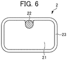
- such a superconducting material is, for example, a resin coated superconducting wire 2 including a superconducting wire 22 such as a NbTi wire, a copper stabilizer 21 called a copper channel coating the superconducting wire 22, and a braided resin 23 such as polyester around the copper stabilizer 21.
- a resin coated superconducting wire 2 by coating the superconducting wire 22 with the copper stabilizer 21, the heat generated from the superconducting wire 22 is released to the outside to suppress an increase in temperature, for example, with immersing the resin coated superconducting wire 2 into a liquid helium.
- Patent Document 1 discloses a superconducting wire which includes multiple superconducting wires, a copper stabilizer in which the superconducting wires are embedded, a resin coating the copper stabilizer, and an additional copper stabilizer coating the resin.
- Patent Document 1 Japanese Unexamined Patent Application (Translation of PCT Application), Publication No. 2017-533579
- the present disclosure has been provided in view of the circumstances mentioned above, and it is an object of the present disclosure to provide a resin coated superconducting wire that is lightweight, highly flexible, and inexpensive as compared to conventional ones.
- the present disclosure makes it possible to provide a resin coated superconducting wire that is lightweight, highly flexible, and inexpensive as compared to conventional ones.
- the present inventors have completed the present disclosure based on findings that designing a resin coated superconducting wire including a matrix resin including a synthetic resin material, and a superconducting wire in the matrix resin, in which, in a transverse cross section of the resin coated superconducting wire, a cross section area of the matrix resin is equal to or larger than that of the superconducting wire makes it possible to provide a resin coated superconducting wire that is lightweight, highly flexible, and inexpensive as compared to a conventional resin coated superconducting wire.
- the resin coated superconducting wire according to the present disclosure includes a matrix resin including a synthetic resin material, and a superconducting wire in the matrix resin.
- a cross section area of the matrix resin is equal to or larger than the cross section area of the superconducting wire.
- FIG. 1 is a transverse cross sectional view of a resin coated superconducting wire according to an embodiment of the present disclosure
- FIG. 2 is a transverse cross sectional view of a resin coated superconducting wire according to another embodiment of the present disclosure
- the resin coated superconducting wire 1 includes a matrix resin 11 including a synthetic resin material, and a superconducting wire 12 in the matrix resin 11.
- the cross section area of the matrix resin 11 is equal to or larger than the cross section area of the superconducting wire 12.
- the resin coated superconducting wires 1 shown in FIGS. 1 to 2 are each a monolayer coated wire in which the matrix resin 11 includes a single matrix resin layer covering the outer circumference of the superconducting wire 12.
- the resin coated superconducting wire 1 should be coiled such that adjacent portions of the coiled superconducting wire 12 are apart from each other at a constant distance.
- the superconducting wire 12 is provided to extend (preferably embedded) in the matrix resin 11 having the transverse cross section area equal to or larger than the transverse cross section area of the superconducting wire 12. This feature allows the matrix resin 11 to serve as what is called a spacer in the resin coated superconducting wire, so that the superconducting wire 12 can be coiled with its adjacent portions kept apart from each other at a constant distance.
- the matrix resin 11 includes a synthetic resin material.
- the matrix resin 11 provides reliable insulation between portions of the superconducting wire 12 and serves as what is called a spacer as mentioned above so that adjacent portions of the superconducting wire 12 can be kept apart from each other at a constant distance. It should be noted that the matrix resin is solid, which is intended to exclude fiber knitting.
- the matrix resin 11 is preferably a thermoplastic resin which can be subjected to extrusion molding.
- the extrusion molding is an effective method for forming a thick coating such that the cross section area of the matrix resin 11 is equal to or larger than that of the superconducting wire 12 in the transverse cross section of the resin coated superconducting wire 1.
- the matrix resin 11 is more preferably a polyamide or a polyolefin.
- the polyamide is preferably nylon.
- the thermoplastic resin is preferably, for example, polyethylene, polypropylene, polystyrene, nylon 11, nylon 12, nylon 6, nylon 66, nylon 610, nylon MXD6 (a polycondensate of m-xylylenediamine and adipic acid), polyethylene terephthalate, polybutylene terephthalate, polyethylene naphthalate, polyphenylene sulfide, tetrafluoroethylene-hexafluoropropylene copolymer resin (FEP), tetrafluoroethylene-ethylene copolymer resin (ETFE), polycarbonate, polyphenylene ether, polyetherimide, or polyether sulfone. These resins may be used alone, or a mixture of two or more of these resins may be used.
- the synthetic resin material included in the matrix resin 11 is not only that the matrix resin 11 consists of a synthetic resin material but also that the matrix resin 11 is a resin composition based on a synthetic resin material.
- a resin composition may contain various additives for use in common resin compositions, such as various fillers, antioxidants, and other additives for improving mechanical or chemical durability.
- the matrix resin 11 may contain a filler so that the matrix resin 11 has a lower heat shrinkage percentage close to the heat shrinkage percentage of the superconducting wire 12 and thus the resin coated superconducting wire 1 has increased heat cycle resistance.
- the matrix resin 11 When the matrix resin 11 is a crystalline resin, the matrix resin 11 preferably has a melting point of, for example, 290°C or less, more preferably 280°C or less, even more preferably 270°C or less.
- the matrix resin 11 is produced by thermoforming a raw material, the raw material with a lower melting point can be molded at a lower temperature, and thus the superconducting wire 12 can be prevented from suffering from performance degradation due to heating during the molding.
- the crystalline resin which may constitute the matrix resin 11, is preferably, for example, polyethylene, polypropylene, nylon 11, nylon 12, nylon 6, nylon 66, nylon 610, nylon MXD6, polyethylene terephthalate, polybutylene terephthalate, polyethylene naphthalate, polyphenylene sulfide, tetrafluoroethylene-hexafluoropropylene copolymer resin (FEP), or tetrafluoroethylene-ethylene copolymer resin (ETFE) .
- the matrix resin 11 preferably has a melting point of 210°C or less, more preferably 200°C or less, even more preferably 190°C or less.
- the crystalline resins for forming the matrix resin 11 polyethylene, polypropylene, nylon 11, and nylon 12 are preferred.
- the matrix resin 11 is preferably nylon or a polyolefin.
- the matrix resin 11 is more preferably nylon 11, nylon 12, nylon 6, nylon 66, nylon 610, nylon MXD6, polyethylene, or polypropylene, and even more preferably nylon 11, nylon 12, polyethylene, or polypropylene since they have particularly low melting points, low heat shrinkage percentages, excellent water absorption resistance (low water absorption rates), excellent flexibility, and excellent mechanical properties.
- the synthetic resin material of the matrix resin 11 preferably has a glass transition point of, for example, 250°C or less, more preferably 240°C or less, even more preferably 230°C or less.
- the lower glass transition point of the raw material allows the resin coating and molding process to be performed at a lower temperature, so that changes in the performance of the superconducting wire 12 due to heating during the thermoforming can be prevented.
- the amorphous resin which may constitute the matrix resin 11, is preferably, for example, polycarbonate, polyphenylene ether, polyetherimide, or polyether sulfone.
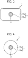
- FIG. 3 is a transverse cross sectional view of another resin coated superconducting wire (rectangular), and FIG. 4 is a transverse cross sectional view of a further resin coated superconducting wire (circular).
- the resin coated superconducting wires 1 shown in FIGS. 3 and 4 are each a multilayer coated wire including a superconducting wire 12, and a matrix resin 11 including multiple matrix resin layers and covering the outer circumference of the superconducting wire 12.
- the matrix resin 11 shown in FIGS. 3 and 4 differs from the matrix resin 11 shown in FIGS. 1 and 2 in that the matrix resin 11 shown in FIGS.
- FIGS. 3 and 4 includes an annular inner matrix resin layer 11a covering the outer circumference of the superconducting wire 12, and at least one outer matrix resin layer 11b covering the outer circumference of the inner matrix resin layer 11a.
- FIGS. 3 to 4 show that the matrix resin 11 has a two-layer structure composed of a single inner matrix resin layer 11a and a single outer matrix resin layer 11b.
- the resin coated superconducting wire 1 is preferably a multilayer coated wire having two or more matrix resin layers, such as the inner matrix resin layer 11a and the outer matrix resin layer 11b, and is more preferably a multilayer coated wire having two or more and four or less matrix resin layers.
- the resin coated superconducting wire 1 is produced in the form of a multilayer coated wire, the resin may be used in a smaller amount per single extrusion coating process, so that the resulting extrusion coated wire is expected to have a higher dimensional accuracy.
- different resins may be used to form the respective matrix resin layers, so that the resin coated superconducting wire 1 can have higher functionality.
- the inner matrix resin layer 11a when the matrix resin includes a polyolefin resin, such as polyethylene or polypropylene, which has low adhesion to the superconducting wire 12, the inner matrix resin layer 11a, which is the first layer from the conductor side, may include an olefin-based resin having at least one functional group selected from the group consisting of an epoxy group, an oxazolyl group, an amino group, and a maleic anhydride residue, or include a copolymer of the olefin-based resin (also referred to as copolymer (A)).
- the inner matrix resin layer 11a enhances the adhesion between the superconducting wire 12 and the outer polyolefin resin 11b.
- the inner matrix resin layer 11a may include an olefin-based copolymer containing a carboxylic acid metal salt (also referred to as olefin-based copolymer (B)).
- the inner matrix resin layer 11a is also expected to enhance the adhesion as mentioned above.
- the olefin component used to form the copolymer (A) is preferably ethylene, propylene, butene-1, pentene-1, 4-methylpentene-1, isobutylene, hexene-1, decene-1, octene-1, 1,4-hexadiene, or dicyclopentadiene, and more preferably ethylene, propylene, or butene-1. These components may be used alone, or two or more of these components may be used.
- the copolymer component used other than the olefin to form the copolymer (A) may be at least one component of an acrylic component and a vinyl component.
- the acrylic component is preferably acrylic acid, methyl acrylate, ethyl acrylate, n-propyl acrylate, isopropyl acrylate, n-butyl acrylate, tert-butyl acrylate, isobutyl acrylate, methyl methacrylate, ethyl methacrylate, or butyl methacrylate.
- the vinyl component is preferably vinyl acetate, vinyl propionate, vinyl butyrate, vinyl chloride, vinyl alcohol, or styrene. Among them, methyl acrylate and methyl methacrylate are more preferred. These components may be used alone, or two or more of these components may be used.
- Typical preferred examples of the copolymer (A) include maleic anhydride-grafted polyethylene or polypropylene, ethylene-glycidyl methacrylate copolymers, and commercially available resins such as Admer (trade name, manufactured by Mitsui Chemicals, Inc.), Bond Fast (trade name, manufactured by Sumitomo Chemical Co., Ltd.), and Lotader (trade name, manufactured by Atofina).
- Admer trade name, manufactured by Mitsui Chemicals, Inc.
- Bond Fast trade name, manufactured by Sumitomo Chemical Co., Ltd.
- Lotader trade name, manufactured by Atofina
- Preferred examples of the carboxylic acid used to form the olefin-based copolymer (B) include unsaturated monocarboxylic acids such as acrylic acid, methacrylic acid, and crotonic acid, and unsaturated dicarboxylic acids such as maleic acid, fumaric acid, and phthalic acid.
- Examples of the metal salt include Zn salts, Na salts, K salts, and Mg salts.
- the olefin-based copolymer (B) is preferably a resin generally called an ionomer, such as Himilan (trade mane, manufactured by Mitsui Polychemicals), in which some parts of the carboxylic acid in the ethylene-methacrylic acid copolymer is a metal salt.
- the matrix resin 11 preferably has a heat shrinkage percentage of 5% or less, more preferably 2% or less, even more preferably 1% or less as calculated using the method shown below. This feature makes the matrix resin 11 less vulnerable to damage or degradation when the matrix resin 11 is immersed in a cooling medium such as liquid helium.
- the resin coated superconducting wire 1 is cut along the longitudinal direction of the resin coated superconducting wire 1 into 0.2 g pieces, each of which is immersed in 500 mL liquid helium for several minutes and then measured for size.
- the matrix resin 11 more preferably has a water absorption rate of 1.0% or less, even more preferably 0.7% or less as calculated using the method shown below.
- the lower the water absorption rate the less likely the surface of the matrix resin 11 is to expand. This feature makes the matrix resin 11 less vulnerable to a reduction in mechanical strength, which is caused by damage, degradation, deterioration, or cracking that occurs when the matrix resin 11 absorbs water.
- the calculation method shown below is one of the methods for determining the water absorption rate of plastics according to JIS K 7209.
- the resin coated superconducting wire 1 is cut along the longitudinal direction of the resin coated superconducting wire 1 into 1.0 g pieces, each of which is immersed in 500 mL water at 23°C for 24 hours, then wiped to remove water from the surface, and then measured for weight.
- the water absorption rate of the resin coated superconducting wire 1 is calculated from the formula (2) below.
- Water absorption rate % the weight of the resin coated superconducting wire before the immersion - the weight of the resin coated superconducting wire after the immersion / the weight of the resin coated superconducting wire before the immersion ⁇ 100
- the superconducting wire 12 is a wire in the matrix resin 11 described above and has superconducting property.
- the size of the transverse cross section of the superconducting wire 12 when the transverse cross section is a circular shape, the size is preferably 0.05 to 2.00 mm ⁇ , more preferably 0.07 to 1.50 mm ⁇ , even more preferably 0.1 to 1.0 mm ⁇ .
- the transverse cross section of the superconducting wire 12 is a rectangular shape, the long side of the rectangular shape is preferably 0.8 mm to 2.5 mm, more preferably 1.5 mm to 2.0 mm, and the short side of the rectangular shape is preferably 0.5 mm to 1.5 mm, more preferably 0.9 mm to 1.2 mm.
- the superconducting wire 12 preferably includes, for example, at least one superconducting material selected from the group consisting of a composite of metal and niobium-titanium, a composite of metal and niobium-3 tin (Nb 3 Sn), a composite of metal and magnesium diboride, a rare earth-based superconducting material, and a bismuth-based superconducting material.
- the composite of metal and niobium-titanium, the composite of metal and niobium-3 tin, or the composite of metal and magnesium diboride refer to a composite in which the metal such as copper or iron covers the surrounding of the niobium-titanium, the niobium-3 tin, or the magnesium diboride.
- Examples of the rare earth-based material include YBa 2 Cu 3 O 7- ⁇ and GdBa 2 Cu 3 O 7- ⁇ .
- Examples of the bismuth-based material include Bi 2 Sr 2 Ca 2 Cu 3 O 10+ ⁇ and Bi 2 Sr 2 CaCu 2 O 8+ ⁇ .
- the superconducting wire 12 may be a single wire or a stranded wire including multiple strands twisted together.
- the cross section area of the matrix resin 11 is equal to or larger than the cross section area of the superconducting wire 12.
- the ratio of the cross section area of the matrix resin 11 to the cross section area of the superconducting wire 12 is preferably 2 or more, more preferably 5 or more, even more preferably 10 or more, further more preferably 20 or more, most preferably 40 or more.
- the ratio of the cross section area preferably has an upper limit of 1000 from practical points of view such as coil material suitability and handleability for coiling operation.
- FIGS. 1 and 2 show a case in which the superconducting wire 12 is located at the center (gravity center) of the matrix resin 11 in the transverse cross section of the resin coated superconducting wire 1.
- the superconducting wire 12 may be located at any position in the matrix resin 11 as long as the superconducting wire 12 remains not exposed from the surface of the resin coated superconducting wire 1 (as long as at least a small amount of the resin component of the matrix resin 11 is present over the surface of the resin coated superconducting wire 1).
- FIGS. 1 and 2 show a case in which the superconducting wire 12 is located at the center (gravity center) of the matrix resin 11 in the transverse cross section of the resin coated superconducting wire 1.
- the superconducting wire 12 may be located at any position in the matrix resin 11 as long as the superconducting wire 12 remains not exposed from the surface of the resin coated superconducting wire 1 (as long as at least a small amount of the resin component of the matrix resin 11 is present over the
- 5A to 5F show modified examples illustrating the transverse cross sections of the resin coated superconducting wires 1A to 1F, which have a rectangular cross section and respectively include the superconducting wires 12A to 12F located at different positions in the transverse cross sections of the matrix resins 11A to 11F.
- the resin coated superconducting wire has one superconducting wire 12 in the form of a single wire or a stranded wire, which is located in one matrix resin 11.
- the resin coated superconducting wire may have any transverse cross section shape such as a circular shape including an elliptic shape, a triangular shape, a square shape, or a rectangular shape.
- the resin coated superconducting wire preferably has a rectangular transverse cross section shape.
- the transverse cross section of the resin coated superconducting wire is a rectangular shape
- the rectangular transverse cross section shape of the resin coated superconducting wire may have a round corner or corners with an R value of 1 mm or less.
- the transverse cross section of the resin coated superconducting wire preferably has a long side of, for example, 0.5 mm to 10 mm, more preferably 1 mm to 7 mm.
- the transverse cross section of the resin coated superconducting wire preferably has a short side of, for example, 0.1 mm to 5 mm, more preferably 0.5 mm to 3 mm.
- the resin coated superconducting wire preferably has a dimensional accuracy of ⁇ 0.10 mm or less in width and a dimensional accuracy of ⁇ 0.10 mm or less in thickness, and more preferably has a dimensional accuracy of ⁇ 0.05 mm or less in width and a dimensional accuracy of ⁇ 0.05 mm or less in thickness.
- the dimensional accuracy refers to the range of difference between the maximum and minimum of a dimension of a piece of the resin coated superconducting wire.
- the resin coated superconducting wire with such a dimensional accuracy as mentioned above provides higher electromagnetic shielding performance.
- Such a dimensional accuracy may be achieved by a method of cutting the outer surface of a product resulting from resin extrusion process.
- such a dimensional accuracy may be achieved by a method of coating the surface of the matrix resin with, for example, a UV-curable resin material.
- the resin coated superconducting wire described above may be used to form a superconducting coil, specifically, a shield coil for use in NMR systems and MRI inspection systems.
- the voltage is preferably 0 to 50 V, more preferably 0 to 20 V, even more preferably 0 to 10 V.
- the resin coated superconducting wire is lightweight, inexpensive, improved in flexibility, and less likely to have a bending habit, and is easy to coil because it has high flexibility or bendability and good handleability.
- the resin coated superconducting wire according to the embodiment described above may be produced, for example, using an extrusion process similar to a common process for forming an extruded resin material, which inserts a superconducting wire into a synthetic resin raw material for forming a matrix resin and then extrudes the raw material.
- the heating temperature, the extrusion rate, and other conditions may be appropriately adjusted depending on the kind of the synthetic resin raw material and the size and shape of the product to be formed.
- a conventional technique includes two steps including covering a superconducting strand with a resin and then embedding the strand in a copper channel.
- the resin coated superconducting wire according to the embodiment can be completed using a single step instead of the conventional two steps because the matrix resin can be shaped into the same form as that of the copper channel.
- the synthetic resin raw materials used were nylon 11 (BESN Noir TN manufactured by Arkema), nylon 12 (UBESTA 3030LUX manufactured by Ube Industries, Ltd.), nylon 6 (UBESTA 1024JI manufactured by Ube Industries, Ltd.), nylon 66 (Leona ® 1300S manufactured by Asahi Kasei Corporation), and high-density polyethylene (Suntech ® -HD B891 manufactured by Asahi Kasei Corporation).
- a superconducting wire with 0.3 mm ⁇ of a composite of copper and niobium-titanium was inserted into the synthetic resin raw material and then subjected to an extrusion process at a temperature equal to or more than a temperature that is obtained by adding the melting point of each resin raw material and 20°C and equal to or less than a temperature that is obtained by adding the melting point of each resin raw material and 80°C using a die for forming a rectangular product (Examples 1 to 20) or a circular product (Examples 21 to 40) having the dimensions shown in Table 2 or 3 below.
- the superconducting wire was placed at the center of the synthetic resin material.
- a resin coated superconducting wire having a rectangular transverse cross section was produced in each of Examples 1 to 20.
- a resin coated superconducting wire having a circular transverse cross section was produced in each of Examples 21 to 40.
- the synthetic resin raw material used was high-density polyethylene (Suntech ® -HD B891 manufactured by Asahi Kasei Corporation).
- a superconducting wire with 0.3 mm ⁇ of a composite of copper and niobium-titanium coated with 20 ⁇ m-thick modified low-density polyethylene having a graft-copolymerized maleic anhydride moiety (Admer NB508 manufactured by Mitsui Chemicals, Inc.) was inserted into the synthetic resin raw material and then subjected to an extrusion process at a temperature equal to or more than a temperature that is obtained by adding the melting point of each resin raw material and 20°C and equal to or less than a temperature that is obtained by adding the melting point of each resin raw material and 80°C using a die for forming a rectangular product having the dimensions shown in Table 4 below.
- the superconducting wire was placed at the center of the synthetic resin material.
- a resin coated superconducting wire was obtained as in Example 41 except that a superconducting wire with 0.3 mm ⁇ of a composite of copper and niobium-titanium coated with 20 ⁇ m-thick ethylene-methacrylic acid copolymer in which some parts of the carboxylic acid was a metal salt (Himilan 1855 manufactured by Mitsui Polychemicals) was used instead.
- the synthetic resin raw material used was high-density polyethylene (Suntech ® -HD B891 manufactured by Asahi Kasei Corporation).
- a superconducting wire with 0.3 mm ⁇ of a composite of copper and niobium-titanium coated with 20 ⁇ m-thick modified low-density polyethylene having a graft-copolymerized maleic anhydride moiety (Admer NB508 manufactured by Mitsui Chemicals, Inc.) was inserted into the synthetic resin raw material and then subjected to an extrusion process at a temperature equal to or more than a temperature that is obtained by adding the melting point of each resin raw material and 20°C and equal to or less than a temperature that is obtained by adding the melting point of each resin raw material and 80°C using a die for forming a circular product having the dimensions shown in Table 5 below.
- the superconducting wire was placed at the center of the synthetic resin material.
- the cross section area of the matrix resin was calculated by determining, in the transverse cross section of the resin coated superconducting wire, the cross section area of the resin coated superconducting wire from the external dimensions of the resin coated superconducting wire and then subtracting the cross section area of the superconducting wire from the determined cross section area.
- the calculated cross section area of the matrix resin was used to calculate the weight and cost of the resin per 1000 m length of the resin coated superconducting wire and the cost relative to those of copper. The results are shown in Tables 2 to 5 below. In Tables 2 to 5, the parenthesized values indicate the values calculated in terms of copper.
- Table 1 shows the melting point, the glass transition point, the heat shrinkage percentage, and the water absorption rate of each of the synthetic resin materials used in Examples 1 to 43.
- the heat shrinkage percentage and the water absorption rate were determined by the methods described above.
- Resin Melting point [°C] Glass transition point
- Heat shrinkage percentage [%] Water absorption rate [%] Nylon 11 186 46 ⁇ 5 0.4 Nylon 12 180 37 ⁇ 5 0.4 Nylon 6 221 45 ⁇ 5 1.7 Nylon 66 258 47 ⁇ 5 1.7 Polyethylene 141 -45 ⁇ 5 0.04
- Ethylene-methacrylic acid copolymer 86 ⁇ 0 ⁇ 5 ⁇ 0.5
- Resin Resin coated superconducting wire Cross section area ratio (matrix resin/super conducting wire) Resin weight per 1000 m [kg] Material cost ratio per unit length (cost ratio of resin/copper) External dimensions [mm] Cross section
- Tables 2 to 5 also show that the resin coated superconducting wires of Examples 1 to 43 can attain a significantly reduced weight and a reduced material cost as compared to copper coated superconducting wire.
Landscapes
- Physics & Mathematics (AREA)
- Spectroscopy & Molecular Physics (AREA)
- Engineering & Computer Science (AREA)
- Power Engineering (AREA)
- Chemical & Material Sciences (AREA)
- Chemical Kinetics & Catalysis (AREA)
- Superconductors And Manufacturing Methods Therefor (AREA)
- Magnetic Resonance Imaging Apparatus (AREA)
Abstract
Description
- The present disclosure relates to a resin coated superconducting wire, a superconducting coil, and a shield coil.
- In the conventional art, a superconducting material is used as a shield coil in applications, such as nuclear magnetic resonance (NMR) systems and systems for magnetic resonance imaging (MRI) inspection. In such applications, the shield coil is used to shield the magnetic field applied from outside to inside so that proper analysis results are obtained, and is used to shield the magnetic field applied from inside to outside so that the human body and the electronic equipment are protected from the effect of the magnetic field.
- Referring to
FIG. 6 , such a superconducting material is, for example, a resin coatedsuperconducting wire 2 including asuperconducting wire 22 such as a NbTi wire, acopper stabilizer 21 called a copper channel coating thesuperconducting wire 22, and abraided resin 23 such as polyester around thecopper stabilizer 21. In such a resin coatedsuperconducting wire 2, by coating thesuperconducting wire 22 with thecopper stabilizer 21, the heat generated from thesuperconducting wire 22 is released to the outside to suppress an increase in temperature, for example, with immersing the resin coatedsuperconducting wire 2 into a liquid helium. - Moreover, in order to increase a heat generating efficiency of a superconducting material,
Patent Document 1 discloses a superconducting wire which includes multiple superconducting wires, a copper stabilizer in which the superconducting wires are embedded, a resin coating the copper stabilizer, and an additional copper stabilizer coating the resin. - Patent Document 1:
Japanese Unexamined Patent Application (Translation of PCT Application), Publication No. 2017-533579 - Unfortunately, the conventional superconducting materials mentioned above, which include high-purity metal such as copper stabilizer around the superconducting wire, are relatively expensive and heavy and have low handleability because they tend to have a bending habit.
- The present disclosure has been provided in view of the circumstances mentioned above, and it is an object of the present disclosure to provide a resin coated superconducting wire that is lightweight, highly flexible, and inexpensive as compared to conventional ones.
-
- [1] A resin coated superconducting wire including: a matrix resin including a synthetic resin material; and a superconducting wire in the matrix resin, in which, in a transverse cross section of the resin coated superconducting wire, a cross section area of the matrix resin is equal to or larger than that of the superconducting wire.
- [2] The resin coated superconducting wire according to [1], in which the superconducting wire includes one or more selected from the group consisting of a composite of metal and niobium-titanium, a composite of metal and niobium-3 tin (Nb3Sn), a composite of metal and magnesium diboride, a rare earth-based superconducting material, and a bismuth-based superconducting material.
- [3] The resin coated superconducting wire according to [1] or [2], in which the synthetic resin material is a thermoplastic resin.
- [4] The resin coated superconducting wire according to [3], in which the thermoplastic resin has a melting point of 290°C or less.
- [5] The resin coated superconducting wire according to [3] or [4], in which the thermoplastic resin has a melting point of 210°C or less.
- [6] The resin coated superconducting wire according to any one of [1] to [5], in which the synthetic resin material is a polyamide or a polyolefin.
- [7] The resin coated superconducting wire according to [6], in which the polyamide is nylon.
- [8] The resin coated superconducting wire according to any one of [1] to [7], in which the synthetic resin material is
nylon 11,nylon 12, or polyethylene. - [9] The resin coated superconducting wire according to any one of [1] to [5], in which the synthetic resin material is an amorphous resin having a glass transition point of 250°C or less.
- [10] The resin coated superconducting wire according to any one of [1] to [9], in which the resin coated superconducting wire is a multilayer coated wire, and the matrix resin includes two or more matrix resin layers including an inner matrix resin layer covering an outer circumference of the superconducting wire and at least one outer matrix resin layer covering an outer circumference of the inner matrix resin layer.
- [11] The resin coated superconducting wire according to [10], in which the inner matrix resin layer includes an olefin-based resin having at least one functional group selected from the group consisting of an epoxy group, an oxazolyl group, an amino group, and a maleic anhydride residue, or includes a copolymer of the olefin-based resin.
- [12] The resin coated superconducting wire according to [10], in which the inner matrix resin layer includes an olefin-based copolymer containing a carboxylic acid metal salt.
- [13] The resin coated superconducting wire according to any one of [1] to [12], in which the superconducting wire is a single wire.
- [14] The resin coated superconducting wire according to any one of [1] to [12], in which the superconducting wire is a stranded wire.
- [15] The resin coated superconducting wire according to any one of [1] to [14], in which a transverse section of the resin coated superconducting wire has a rectangular shape.
- [16] The resin coated superconducting wire according to any one of [1] to [14], in which a transverse section of the resin coated superconducting wire has a circular shape.
- [17] The resin coated superconducting wire according to any one of [1] to [16], in which the resin coated superconducting wire has a dimensional accuracy of ±0.10 mm or less in width and a dimensional accuracy of ±0.10 mm or less in thickness.
- [18] The resin coated superconducting wire according to any one of [1] to [17], in which the resin coated superconducting wire has a dimensional accuracy of ±0.05 mm or less in width and a dimensional accuracy of ±0.05 mm or less in thickness.
- [19] A superconducting coil including the resin coated superconducting wire according to any one of [1] to [18].
- [20] A shield coil including the resin coated superconducting wire according to any one of [1] to [18].
- The present disclosure makes it possible to provide a resin coated superconducting wire that is lightweight, highly flexible, and inexpensive as compared to conventional ones.
-
-
FIG. 1 is a transverse cross sectional view of a resin coated superconducting wire (rectangular) according to an embodiment of the present disclosure. -
FIG. 2 is a transverse cross sectional view of a resin coated superconducting wire (circular) according to an embodiment of the present disclosure. -
FIG. 3 is a transverse cross sectional view of a resin coated superconducting wire (rectangular) according to an embodiment of the present disclosure. -
FIG. 4 is a transverse cross sectional view of a resin coated superconducting wire (circular) according to an embodiment of the present disclosure. -
FIGS. 5A to 5F are transverse cross sectional views showing different modifications of a resin coated superconducting wire (rectangular). -
FIG. 6 is a transverse cross sectional view of a conventional resin coated superconducting wire. - Hereinafter, preferred embodiments of the present disclosure will be described in detail, which are not intended to limit the present disclosure.
- The present inventors have completed the present disclosure based on findings that designing a resin coated superconducting wire including a matrix resin including a synthetic resin material, and a superconducting wire in the matrix resin, in which, in a transverse cross section of the resin coated superconducting wire, a cross section area of the matrix resin is equal to or larger than that of the superconducting wire makes it possible to provide a resin coated superconducting wire that is lightweight, highly flexible, and inexpensive as compared to a conventional resin coated superconducting wire.
- The resin coated superconducting wire according to the present disclosure includes a matrix resin including a synthetic resin material, and a superconducting wire in the matrix resin. In the resin coated superconducting wire, when seen a transverse cross section of the resin coated superconducting wire, a cross section area of the matrix resin is equal to or larger than the cross section area of the superconducting wire.
-
FIG. 1 is a transverse cross sectional view of a resin coated superconducting wire according to an embodiment of the present disclosure, andFIG. 2 is a transverse cross sectional view of a resin coated superconducting wire according to another embodiment of the present disclosure. As shown inFIGS. 1 to 2 , the resin coatedsuperconducting wire 1 includes amatrix resin 11 including a synthetic resin material, and asuperconducting wire 12 in thematrix resin 11. According to the embodiment, in the transverse cross section of the resin coatedsuperconducting wire 1, the cross section area of thematrix resin 11 is equal to or larger than the cross section area of thesuperconducting wire 12. The resin coatedsuperconducting wire 1 shown inFIG. 1 has a rectangular transverse cross section, while the resin coatedsuperconducting wire 1 shown inFIG. 2 has a circular transverse cross section. The resin coatedsuperconducting wires 1 shown inFIGS. 1 to 2 are each a monolayer coated wire in which thematrix resin 11 includes a single matrix resin layer covering the outer circumference of thesuperconducting wire 12. - In shield coil applications, a relatively small current is allowed to flow through the
superconducting wire 12 of the resin coatedsuperconducting wire 1. In such applications, therefore, thesuperconducting wire 12 is less likely to be quenched. Even in case of quench, thesuperconducting wire 12 does not need to be combined with a large amount of copper stabilizer since the current in thesuperconducting wire 12 is small. On the other hand, to provide a shield coil with reliable magnetic field shielding performance, the resin coatedsuperconducting wire 1 should be coiled such that adjacent portions of the coiledsuperconducting wire 12 are apart from each other at a constant distance. Therefore, thesuperconducting wire 12 is provided to extend (preferably embedded) in thematrix resin 11 having the transverse cross section area equal to or larger than the transverse cross section area of thesuperconducting wire 12. This feature allows thematrix resin 11 to serve as what is called a spacer in the resin coated superconducting wire, so that thesuperconducting wire 12 can be coiled with its adjacent portions kept apart from each other at a constant distance. - The
matrix resin 11 includes a synthetic resin material. Thematrix resin 11 provides reliable insulation between portions of thesuperconducting wire 12 and serves as what is called a spacer as mentioned above so that adjacent portions of thesuperconducting wire 12 can be kept apart from each other at a constant distance. It should be noted that the matrix resin is solid, which is intended to exclude fiber knitting. - The
matrix resin 11 is preferably a thermoplastic resin which can be subjected to extrusion molding. The extrusion molding is an effective method for forming a thick coating such that the cross section area of thematrix resin 11 is equal to or larger than that of thesuperconducting wire 12 in the transverse cross section of the resin coatedsuperconducting wire 1. Thematrix resin 11 is more preferably a polyamide or a polyolefin. The polyamide is preferably nylon. The thermoplastic resin is preferably, for example, polyethylene, polypropylene, polystyrene,nylon 11,nylon 12, nylon 6, nylon 66, nylon 610, nylon MXD6 (a polycondensate of m-xylylenediamine and adipic acid), polyethylene terephthalate, polybutylene terephthalate, polyethylene naphthalate, polyphenylene sulfide, tetrafluoroethylene-hexafluoropropylene copolymer resin (FEP), tetrafluoroethylene-ethylene copolymer resin (ETFE), polycarbonate, polyphenylene ether, polyetherimide, or polyether sulfone. These resins may be used alone, or a mixture of two or more of these resins may be used. - The synthetic resin material included in the
matrix resin 11 is not only that thematrix resin 11 consists of a synthetic resin material but also that thematrix resin 11 is a resin composition based on a synthetic resin material. Such a resin composition may contain various additives for use in common resin compositions, such as various fillers, antioxidants, and other additives for improving mechanical or chemical durability. For example, thematrix resin 11 may contain a filler so that thematrix resin 11 has a lower heat shrinkage percentage close to the heat shrinkage percentage of thesuperconducting wire 12 and thus the resin coatedsuperconducting wire 1 has increased heat cycle resistance. - When the
matrix resin 11 is a crystalline resin, thematrix resin 11 preferably has a melting point of, for example, 290°C or less, more preferably 280°C or less, even more preferably 270°C or less. When thematrix resin 11 is produced by thermoforming a raw material, the raw material with a lower melting point can be molded at a lower temperature, and thus thesuperconducting wire 12 can be prevented from suffering from performance degradation due to heating during the molding. - The crystalline resin, which may constitute the
matrix resin 11, is preferably, for example, polyethylene, polypropylene,nylon 11,nylon 12, nylon 6, nylon 66, nylon 610, nylon MXD6, polyethylene terephthalate, polybutylene terephthalate, polyethylene naphthalate, polyphenylene sulfide, tetrafluoroethylene-hexafluoropropylene copolymer resin (FEP), or tetrafluoroethylene-ethylene copolymer resin (ETFE) . - For the purpose of further preventing the heating-induced degradation of the performance of the
superconducting wire 12 during the molding, thematrix resin 11 preferably has a melting point of 210°C or less, more preferably 200°C or less, even more preferably 190°C or less. Among the crystalline resins for forming thematrix resin 11, polyethylene, polypropylene,nylon 11, andnylon 12 are preferred. - The
matrix resin 11 is preferably nylon or a polyolefin. In particular, thematrix resin 11 is more preferablynylon 11,nylon 12, nylon 6, nylon 66, nylon 610, nylon MXD6, polyethylene, or polypropylene, and even more preferablynylon 11,nylon 12, polyethylene, or polypropylene since they have particularly low melting points, low heat shrinkage percentages, excellent water absorption resistance (low water absorption rates), excellent flexibility, and excellent mechanical properties. - When the
matrix resin 11 is an amorphous resin, the synthetic resin material of thematrix resin 11 preferably has a glass transition point of, for example, 250°C or less, more preferably 240°C or less, even more preferably 230°C or less. For example, when thematrix resin 11 is produced by thermoforming a raw material, the lower glass transition point of the raw material allows the resin coating and molding process to be performed at a lower temperature, so that changes in the performance of thesuperconducting wire 12 due to heating during the thermoforming can be prevented. - The amorphous resin, which may constitute the
matrix resin 11, is preferably, for example, polycarbonate, polyphenylene ether, polyetherimide, or polyether sulfone. -
FIG. 3 is a transverse cross sectional view of another resin coated superconducting wire (rectangular), andFIG. 4 is a transverse cross sectional view of a further resin coated superconducting wire (circular). The resin coatedsuperconducting wires 1 shown inFIGS. 3 and 4 are each a multilayer coated wire including asuperconducting wire 12, and amatrix resin 11 including multiple matrix resin layers and covering the outer circumference of thesuperconducting wire 12. Specifically, thematrix resin 11 shown inFIGS. 3 and 4 differs from thematrix resin 11 shown inFIGS. 1 and 2 in that thematrix resin 11 shown inFIGS. 3 and 4 includes an annular innermatrix resin layer 11a covering the outer circumference of thesuperconducting wire 12, and at least one outermatrix resin layer 11b covering the outer circumference of the innermatrix resin layer 11a.FIGS. 3 to 4 show that thematrix resin 11 has a two-layer structure composed of a single innermatrix resin layer 11a and a single outermatrix resin layer 11b. - As shown in
FIGS. 3 and 4 , the resin coatedsuperconducting wire 1 is preferably a multilayer coated wire having two or more matrix resin layers, such as the innermatrix resin layer 11a and the outermatrix resin layer 11b, and is more preferably a multilayer coated wire having two or more and four or less matrix resin layers. When the resin coatedsuperconducting wire 1 is produced in the form of a multilayer coated wire, the resin may be used in a smaller amount per single extrusion coating process, so that the resulting extrusion coated wire is expected to have a higher dimensional accuracy. Moreover, different resins may be used to form the respective matrix resin layers, so that the resin coatedsuperconducting wire 1 can have higher functionality. - Specifically, when the matrix resin includes a polyolefin resin, such as polyethylene or polypropylene, which has low adhesion to the
superconducting wire 12, the innermatrix resin layer 11a, which is the first layer from the conductor side, may include an olefin-based resin having at least one functional group selected from the group consisting of an epoxy group, an oxazolyl group, an amino group, and a maleic anhydride residue, or include a copolymer of the olefin-based resin (also referred to as copolymer (A)). In such a multilayer coated wire, the innermatrix resin layer 11a enhances the adhesion between thesuperconducting wire 12 and theouter polyolefin resin 11b. Alternatively, the innermatrix resin layer 11a may include an olefin-based copolymer containing a carboxylic acid metal salt (also referred to as olefin-based copolymer (B)). In such a multilayer coated wire, the innermatrix resin layer 11a is also expected to enhance the adhesion as mentioned above. - The olefin component used to form the copolymer (A) is preferably ethylene, propylene, butene-1, pentene-1, 4-methylpentene-1, isobutylene, hexene-1, decene-1, octene-1, 1,4-hexadiene, or dicyclopentadiene, and more preferably ethylene, propylene, or butene-1. These components may be used alone, or two or more of these components may be used.
- The copolymer component used other than the olefin to form the copolymer (A) may be at least one component of an acrylic component and a vinyl component.
- The acrylic component is preferably acrylic acid, methyl acrylate, ethyl acrylate, n-propyl acrylate, isopropyl acrylate, n-butyl acrylate, tert-butyl acrylate, isobutyl acrylate, methyl methacrylate, ethyl methacrylate, or butyl methacrylate. The vinyl component is preferably vinyl acetate, vinyl propionate, vinyl butyrate, vinyl chloride, vinyl alcohol, or styrene. Among them, methyl acrylate and methyl methacrylate are more preferred. These components may be used alone, or two or more of these components may be used. Typical preferred examples of the copolymer (A) include maleic anhydride-grafted polyethylene or polypropylene, ethylene-glycidyl methacrylate copolymers, and commercially available resins such as Admer (trade name, manufactured by Mitsui Chemicals, Inc.), Bond Fast (trade name, manufactured by Sumitomo Chemical Co., Ltd.), and Lotader (trade name, manufactured by Atofina).
- Preferred examples of the carboxylic acid used to form the olefin-based copolymer (B) include unsaturated monocarboxylic acids such as acrylic acid, methacrylic acid, and crotonic acid, and unsaturated dicarboxylic acids such as maleic acid, fumaric acid, and phthalic acid. Examples of the metal salt include Zn salts, Na salts, K salts, and Mg salts. The olefin-based copolymer (B) is preferably a resin generally called an ionomer, such as Himilan (trade mane, manufactured by Mitsui Polychemicals), in which some parts of the carboxylic acid in the ethylene-methacrylic acid copolymer is a metal salt.
- The
matrix resin 11 preferably has a heat shrinkage percentage of 5% or less, more preferably 2% or less, even more preferably 1% or less as calculated using the method shown below. This feature makes thematrix resin 11 less vulnerable to damage or degradation when thematrix resin 11 is immersed in a cooling medium such as liquid helium. - The resin coated
superconducting wire 1 is cut along the longitudinal direction of the resin coatedsuperconducting wire 1 into 0.2 g pieces, each of which is immersed in 500 mL liquid helium for several minutes and then measured for size. The heat shrinkage percentage of the resin coatedsuperconducting wire 1 is calculated from the formula (1) below.
- The
matrix resin 11 more preferably has a water absorption rate of 1.0% or less, even more preferably 0.7% or less as calculated using the method shown below. The lower the water absorption rate, the less likely the surface of thematrix resin 11 is to expand. This feature makes thematrix resin 11 less vulnerable to a reduction in mechanical strength, which is caused by damage, degradation, deterioration, or cracking that occurs when thematrix resin 11 absorbs water. The calculation method shown below is one of the methods for determining the water absorption rate of plastics according to JIS K 7209. - The resin coated
superconducting wire 1 is cut along the longitudinal direction of the resin coatedsuperconducting wire 1 into 1.0 g pieces, each of which is immersed in 500 mL water at 23°C for 24 hours, then wiped to remove water from the surface, and then measured for weight. The water absorption rate of the resin coatedsuperconducting wire 1 is calculated from the formula (2) below.
- The
superconducting wire 12 is a wire in thematrix resin 11 described above and has superconducting property. - As a size of the transverse cross section of the
superconducting wire 12, when the transverse cross section is a circular shape, the size is preferably 0.05 to 2.00 mmϕ, more preferably 0.07 to 1.50 mmϕ, even more preferably 0.1 to 1.0 mmϕ. When the transverse cross section of thesuperconducting wire 12 is a rectangular shape, the long side of the rectangular shape is preferably 0.8 mm to 2.5 mm, more preferably 1.5 mm to 2.0 mm, and the short side of the rectangular shape is preferably 0.5 mm to 1.5 mm, more preferably 0.9 mm to 1.2 mm. - The
superconducting wire 12 preferably includes, for example, at least one superconducting material selected from the group consisting of a composite of metal and niobium-titanium, a composite of metal and niobium-3 tin (Nb3Sn), a composite of metal and magnesium diboride, a rare earth-based superconducting material, and a bismuth-based superconducting material. In this regard, the composite of metal and niobium-titanium, the composite of metal and niobium-3 tin, or the composite of metal and magnesium diboride refer to a composite in which the metal such as copper or iron covers the surrounding of the niobium-titanium, the niobium-3 tin, or the magnesium diboride. - Examples of the rare earth-based material include YBa2Cu3O7-δ and GdBa2Cu3O7-δ. Examples of the bismuth-based material include Bi2Sr2Ca2Cu3O10+δ and Bi2Sr2CaCu2O8+δ.
- The
superconducting wire 12 may be a single wire or a stranded wire including multiple strands twisted together. - As described above, in the resin coated
superconducting wire 1, when seen the transverse cross section of the resin coatedsuperconducting wire 1, the cross section area of thematrix resin 11 is equal to or larger than the cross section area of thesuperconducting wire 12. - In the transverse cross section of the resin coated
superconducting wire 1, the ratio of the cross section area of thematrix resin 11 to the cross section area of the superconducting wire 12 (the cross section area of thematrix resin 11/the cross section area of the superconducting wire 12) is preferably 2 or more, more preferably 5 or more, even more preferably 10 or more, further more preferably 20 or more, most preferably 40 or more. The ratio of the cross section area preferably has an upper limit of 1000 from practical points of view such as coil material suitability and handleability for coiling operation. -
FIGS. 1 and 2 show a case in which thesuperconducting wire 12 is located at the center (gravity center) of thematrix resin 11 in the transverse cross section of the resin coatedsuperconducting wire 1. However, thesuperconducting wire 12 may be located at any position in thematrix resin 11 as long as thesuperconducting wire 12 remains not exposed from the surface of the resin coated superconducting wire 1 (as long as at least a small amount of the resin component of thematrix resin 11 is present over the surface of the resin coated superconducting wire 1). For example,FIGS. 5A to 5F show modified examples illustrating the transverse cross sections of the resin coatedsuperconducting wires 1A to 1F, which have a rectangular cross section and respectively include thesuperconducting wires 12A to 12F located at different positions in the transverse cross sections of the matrix resins 11A to 11F. - The resin coated superconducting wire has one
superconducting wire 12 in the form of a single wire or a stranded wire, which is located in onematrix resin 11. - The resin coated superconducting wire may have any transverse cross section shape such as a circular shape including an elliptic shape, a triangular shape, a square shape, or a rectangular shape. For ease of coiling, the resin coated superconducting wire preferably has a rectangular transverse cross section shape. When the transverse cross section of the resin coated superconducting wire is a rectangular shape, the rectangular transverse cross section shape of the resin coated superconducting wire may have a round corner or corners with an R value of 1 mm or less.
- When the resin coated superconducting wire has a rectangular shape, the transverse cross section of the resin coated superconducting wire preferably has a long side of, for example, 0.5 mm to 10 mm, more preferably 1 mm to 7 mm. The transverse cross section of the resin coated superconducting wire preferably has a short side of, for example, 0.1 mm to 5 mm, more preferably 0.5 mm to 3 mm.
- The resin coated superconducting wire preferably has a dimensional accuracy of ±0.10 mm or less in width and a dimensional accuracy of ±0.10 mm or less in thickness, and more preferably has a dimensional accuracy of ±0.05 mm or less in width and a dimensional accuracy of ±0.05 mm or less in thickness. As used herein, the dimensional accuracy refers to the range of difference between the maximum and minimum of a dimension of a piece of the resin coated superconducting wire. The resin coated superconducting wire with such a dimensional accuracy as mentioned above provides higher electromagnetic shielding performance. Such a dimensional accuracy may be achieved by a method of cutting the outer surface of a product resulting from resin extrusion process. Alternatively, such a dimensional accuracy may be achieved by a method of coating the surface of the matrix resin with, for example, a UV-curable resin material.
- The resin coated superconducting wire described above may be used to form a superconducting coil, specifically, a shield coil for use in NMR systems and MRI inspection systems.
- As a voltage applied to the above resin coated superconducting wire, the voltage, but is not limited, is preferably 0 to 50 V, more preferably 0 to 20 V, even more preferably 0 to 10 V.
- As compared to conventional superconducting wires including copper stabilizer, the resin coated superconducting wire is lightweight, inexpensive, improved in flexibility, and less likely to have a bending habit, and is easy to coil because it has high flexibility or bendability and good handleability.
- The resin coated superconducting wire according to the embodiment described above may be produced, for example, using an extrusion process similar to a common process for forming an extruded resin material, which inserts a superconducting wire into a synthetic resin raw material for forming a matrix resin and then extrudes the raw material. The heating temperature, the extrusion rate, and other conditions may be appropriately adjusted depending on the kind of the synthetic resin raw material and the size and shape of the product to be formed.
- A conventional technique includes two steps including covering a superconducting strand with a resin and then embedding the strand in a copper channel. On the other hand, the resin coated superconducting wire according to the embodiment can be completed using a single step instead of the conventional two steps because the matrix resin can be shaped into the same form as that of the copper channel.
- Next, examples will be described to make clearer the advantageous effects of the present disclosure. It will be understood that the examples are not intended to limit the present disclosure.
- The synthetic resin raw materials used were nylon 11 (BESN Noir TN manufactured by Arkema), nylon 12 (UBESTA 3030LUX manufactured by Ube Industries, Ltd.), nylon 6 (UBESTA 1024JI manufactured by Ube Industries, Ltd.), nylon 66 (Leona® 1300S manufactured by Asahi Kasei Corporation), and high-density polyethylene (Suntech®-HD B891 manufactured by Asahi Kasei Corporation). A superconducting wire with 0.3 mmϕ of a composite of copper and niobium-titanium was inserted into the synthetic resin raw material and then subjected to an extrusion process at a temperature equal to or more than a temperature that is obtained by adding the melting point of each resin raw material and 20°C and equal to or less than a temperature that is obtained by adding the melting point of each resin raw material and 80°C using a die for forming a rectangular product (Examples 1 to 20) or a circular product (Examples 21 to 40) having the dimensions shown in Table 2 or 3 below. As shown in
FIGS. 1 and 2 , the superconducting wire was placed at the center of the synthetic resin material. A resin coated superconducting wire having a rectangular transverse cross section was produced in each of Examples 1 to 20. A resin coated superconducting wire having a circular transverse cross section was produced in each of Examples 21 to 40. - The synthetic resin raw material used was high-density polyethylene (Suntech®-HD B891 manufactured by Asahi Kasei Corporation). A superconducting wire with 0.3 mmϕ of a composite of copper and niobium-titanium coated with 20 µm-thick modified low-density polyethylene having a graft-copolymerized maleic anhydride moiety (Admer NB508 manufactured by Mitsui Chemicals, Inc.) was inserted into the synthetic resin raw material and then subjected to an extrusion process at a temperature equal to or more than a temperature that is obtained by adding the melting point of each resin raw material and 20°C and equal to or less than a temperature that is obtained by adding the melting point of each resin raw material and 80°C using a die for forming a rectangular product having the dimensions shown in Table 4 below. As shown in
FIG. 3 , the superconducting wire was placed at the center of the synthetic resin material. - A resin coated superconducting wire was obtained as in Example 41 except that a superconducting wire with 0.3 mmϕ of a composite of copper and niobium-titanium coated with 20 µm-thick ethylene-methacrylic acid copolymer in which some parts of the carboxylic acid was a metal salt (Himilan 1855 manufactured by Mitsui Polychemicals) was used instead.
- The synthetic resin raw material used was high-density polyethylene (Suntech®-HD B891 manufactured by Asahi Kasei Corporation). A superconducting wire with 0.3 mmϕ of a composite of copper and niobium-titanium coated with 20 µm-thick modified low-density polyethylene having a graft-copolymerized maleic anhydride moiety (Admer NB508 manufactured by Mitsui Chemicals, Inc.) was inserted into the synthetic resin raw material and then subjected to an extrusion process at a temperature equal to or more than a temperature that is obtained by adding the melting point of each resin raw material and 20°C and equal to or less than a temperature that is obtained by adding the melting point of each resin raw material and 80°C using a die for forming a circular product having the dimensions shown in Table 5 below. As shown in
FIG. 4 , the superconducting wire was placed at the center of the synthetic resin material. - The cross section area of the matrix resin was calculated by determining, in the transverse cross section of the resin coated superconducting wire, the cross section area of the resin coated superconducting wire from the external dimensions of the resin coated superconducting wire and then subtracting the cross section area of the superconducting wire from the determined cross section area. The calculated cross section area of the matrix resin was used to calculate the weight and cost of the resin per 1000 m length of the resin coated superconducting wire and the cost relative to those of copper. The results are shown in Tables 2 to 5 below. In Tables 2 to 5, the parenthesized values indicate the values calculated in terms of copper.
- Table 1 shows the melting point, the glass transition point, the heat shrinkage percentage, and the water absorption rate of each of the synthetic resin materials used in Examples 1 to 43. The heat shrinkage percentage and the water absorption rate were determined by the methods described above.
[Table 1] Resin Melting point [°C] Glass transition point [°C] Heat shrinkage percentage [%] Water absorption rate [%] Nylon 11 186 46 <5 0.4 Nylon 12 180 37 <5 0.4 Nylon 6 221 45 <5 1.7 Nylon 66 258 47 <5 1.7 Polyethylene 141 -45 <5 0.04 Modified low-density polyethy lene 120 <0 <5 <0.5 Ethylene-methacrylic acid copolymer 86 <0 <5 <0.5 [Table 2] Resin Resin coated superconducting wire Cross section area ratio (matrix resin/super conducting wire) Resin weight per 1000 m [kg] Material cost ratio per unit length (cost ratio of resin/copper) External dimensions [mm] Cross section area of matrix resin [mm2] Cross section area of supercondu cting wire [mm2] Width Thickness Curvature radius R of corner Example 1 Nylon 11 2.5 1.5 0.3 3.6 0.071 51 4 (33) About 1/3 Example 2 Nylon 11 3.5 2.1 0.3 7.1 0.071 100 8 (64) About 1/3 Example 3 Nylon 11 5 3 0.3 15 0.071 210 16 (133) About 1/3 Example 4 Nylon 11 10.9 6.5 0.3 71 0.071 1000 73 (630) About 1/3 Example 5 Nylon 12 2.5 1.5 0.3 3.6 0.071 51 4 (33) About 1/3 Example 6 Nylon 12 3.5 2.1 0.3 7.1 0.071 100 8 (64) About 1/3 Example 7 Nylon 12 5 3 0.3 15 0.071 210 16 (133) About 1/3 Example 8 Nylon 12 10.9 6.5 0.3 71 0.071 1000 73 (630) About 1/3 Example 9 Nylon 6 2.5 1.5 0.3 3.6 0.071 51 5 (33) About 1/8 Example 10 Nylon 6 3.5 2.1 0.3 7.1 0.071 100 9 (64) About 1/8 Example 11 Nylon 6 5 3 0.3 15 0.071 210 17 (133) About 1/8 Example 12 Nylon 6 10.9 6.5 0.3 71 0.071 1000 80 (630) About 1/8 Example 13 Nylon 66 2.5 1.5 0.3 3.6 0.071 51 5 (33) About 1/6 Example 14 Nylon 66 3.5 2.1 0.3 7.1 0.071 100 9 (64) About 1/6 Example 15 Nylon 66 5 3 0.3 15 0.071 210 17 (133) About 1/6 Example 16 Nylon 66 10.9 6.5 0.3 71 0.071 1000 81 (630) About 1/6 Example 17 Polyethylene 2.5 1.5 0.3 3.6 0.071 51 4 (33) About 1/39 Example 18 Polyethylene 3.5 2.1 0.3 7.1 0.071 100 7 (64) About 1/39 Example 19 Polyethylene 5 3 0.3 15 0.071 210 15 (133) About 1/39 Example 20 Polyethylene 10.9 6.5 0.3 71 0.071 1000 68 (630) About 1/39 [Table 3] Resin Resin coated superconducting wire Cross section area ratio (matrix resin/super conducting wire) Resin weight per 1000 m [kg] Material cost ratio per unit length (cost ratio of resin/copper) External diameter [mm] Cross section area of matrix resin [mm2] Cross section area of superconducting wire [mm2] Example 21 Nylon 11 2.16 3.6 0.071 51 4 (33) About 1/3 Example 22 Nylon 11 3.04 7.1 0.071 100 8 (64) About 1/3 Example 23 Nylon 11 4.36 15 0.071 210 16 (133) About 1/3 Example 24 Nylon 11 9.49 71 0.071 1000 73 (630) About 1/3 Example 25 Nylon 12 2.16 3.6 0.071 51 4 (33) About 1/3 Example 26 Nylon 12 3.04 7.1 0.071 100 8 (64) About 1/3 Example 27 Nylon 12 4.36 15 0.071 210 16 (133) About 1/3 Example 28 Nylon 12 9.49 71 0.071 1000 73 (630) About 1/3 Example 29 Nylon 6 2.16 3.6 0.071 51 5 (33) About 1/8 Example 30 Nylon 6 3.04 7.1 0.071 100 9 (64) About 1/8 Example 31 Nylon 6 4.36 15 0.071 210 17 (133) About 1/8 Example 32 Nylon 6 9.49 71 0.071 1000 80 (630) About 1/8 Example 33 Nylon 66 2.16 3.6 0.071 51 5 (33) About 1/6 Example 34 Nylon 66 3.04 7.1 0.071 100 9 (64) About 1/6 Example 35 Nylon 66 4.36 15 0.071 210 17 (133) About 1/6 Example 36 Nylon 66 9.49 71 0.071 1000 81 (630) About 1/6 Example 37 Polyethylene 2.16 3.6 0.071 51 4 (33) About 1/39 Example 38 Polyethylene 3.04 7.1 0.071 100 7 (64) About 1/39 Example 39 Polyethylene 4.36 15 0.071 210 15 (133) About 1/39 Example 40 Polyethylene 9.49 71 0.071 1000 68 (630) About 1/39 [Table 4] Resin Resin coated superconducting wire Cross section area ratio (matrix resin/super conducting wire) Resin weight per 1000 m [kg] Material cost ratio per unit length (cost ratio of resin/copper) External dimensions [mm] Cross section area of matrix resin [mm2] Cross section area of superconducting wire [mm2] Width Thickness Curvature radius R of corner Example 41 Modified low-density polyethylene/ polyethy lene 2.5 1.5 0.3 3.6 0.071 51 4 (33) About 1/39 Example 42 Ethylene-methacrylic acid copolymer/ polyethy lene 2.5 1.5 0.3 3.6 0.071 51 4 (33) About 1/39 [Table 5] Resin Resin coated superconducting wire Cross section area ratio (matrix resin/super conducting wire) Resin weight per 1000 m [kg] Material cost ratio per unit length (cost ratio of resin/copper) External diameter [mm] Cross section area of matrix resin [mm2] Cross section area of superconducting wire [mm2] Example 43 Modified low-density polyethylene/ polyethylene 2.16 3.6 0.071 51 4 (33) About 1/39 - It has been demonstrated that the resulting resin coated superconducting wires of Examples 1 to 43 have dimensions substantially the same as that of conventional superconducting wire including a copper channel and provide magnetic shielding performance substantially the same as that of conventional superconducting wire including a copper channel.
- Tables 2 to 5 also show that the resin coated superconducting wires of Examples 1 to 43 can attain a significantly reduced weight and a reduced material cost as compared to copper coated superconducting wire.
-
- 1, 1A, 1B, 1C, 1D, 1E, 1F, 2: Resin coated superconducting wire
- 11, 11A, 11B, 11C, 11D, 11E, 11F: Matrix resin
- 11a: Inner matrix resin layer
- 11b: Outer matrix resin layer
- 12, 12A, 12B, 12C, 12D, 12E, 12F, 22: Superconducting wire
- 21: Copper stabilizer
Claims (20)
- A resin coated superconducting wire comprising:a matrix resin comprising a synthetic resin material; anda superconducting wire in the matrix resin,wherein, in a transverse cross section of the resin coated superconducting wire, a cross section area of the matrix resin is equal to or larger than that of the superconducting wire.
- The resin coated superconducting wire according to claim 1, wherein the superconducting wire comprises one or more selected from the group consisting of a composite of metal and niobium-titanium, a composite of metal and niobium-3 tin (Nb3Sn), a composite of metal and magnesium diboride, a rare earth-based superconducting material, and a bismuth-based superconducting material.
- The resin coated superconducting wire according to claim 1 or 2, wherein the synthetic resin material is a thermoplastic resin.
- The resin coated superconducting wire according to claim 3, wherein the thermoplastic resin has a melting point of 290°C or less.
- The resin coated superconducting wire according to claim 3 or 4, wherein the thermoplastic resin has a melting point of 210°C or less.
- The resin coated superconducting wire according to any one of claims 1 to 5, wherein the synthetic resin material is a polyamide or a polyolefin.
- The resin coated superconducting wire according to claim 6, wherein the polyamide is nylon.
- The resin coated superconducting wire according to any one of claims 1 to 7, wherein the synthetic resin material is nylon 11, nylon 12, or polyethylene.
- The resin coated superconducting wire according to any one of claims 1 to 5, wherein the synthetic resin material is an amorphous resin having a glass transition point of 250°C or less.
- The resin coated superconducting wire according to any one of claims 1 to 9, wherein the resin coated superconducting wire is a multilayer coated wire, and the matrix resin comprises two or more matrix resin layers including an inner matrix resin layer covering an outer circumference of the superconducting wire and at least one outer matrix resin layer covering an outer circumference of the inner matrix resin layer.
- The resin coated superconducting wire according to claim 10, wherein the inner matrix resin layer comprises an olefin-based resin having at least one functional group selected from the group consisting of an epoxy group, an oxazolyl group, an amino group, and a maleic anhydride residue, or comprises a copolymer of the olefin-based resin.
- The resin coated superconducting wire according to claim 10, wherein the inner matrix resin layer comprises an olefin-based copolymer containing a carboxylic acid metal salt.
- The resin coated superconducting wire according to any one of claims 1 to 12, wherein the superconducting wire is a single wire.
- The resin coated superconducting wire according to any one of claims 1 to 12, wherein the superconducting wire is a stranded wire.
- The resin coated superconducting wire according to any one of claims 1 to 14, wherein a transverse section of the resin coated superconducting wire has a rectangular shape.
- The resin coated superconducting wire according to any one of claims 1 to 14, wherein a transverse section of the resin coated superconducting wire has a circular shape.
- The resin coated superconducting wire according to any one of claims 1 to 16, wherein the resin coated superconducting wire has a dimensional accuracy of ±0.10 mm or less in width and a dimensional accuracy of ±0.10 mm or less in thickness.
- The resin coated superconducting wire according to any one of claims 1 to 17, wherein the resin coated superconducting wire has a dimensional accuracy of ±0.05 mm or less in width and a dimensional accuracy of ±0.05 mm or less in thickness.
- A superconducting coil comprising the resin coated superconducting wire according to any one of claims 1 to 18.
- A shield coil comprising the resin coated superconducting wire according to any one of claims 1 to 18.
Applications Claiming Priority (2)
| Application Number | Priority Date | Filing Date | Title |
|---|---|---|---|
| JP2019103286 | 2019-05-31 | ||
| PCT/JP2020/021496 WO2020241893A1 (en) | 2019-05-31 | 2020-05-29 | Resin-coated superconducting wire, superconducting coil, and shield coil |
Publications (2)
| Publication Number | Publication Date |
|---|---|
| EP3979264A1 true EP3979264A1 (en) | 2022-04-06 |
| EP3979264A4 EP3979264A4 (en) | 2023-05-31 |
Family
ID=73552838
Family Applications (1)
| Application Number | Title | Priority Date | Filing Date |
|---|---|---|---|
| EP20815589.5A Pending EP3979264A4 (en) | 2019-05-31 | 2020-05-29 | RESIN COATED SUPERCONDUCTING WIRE, SUPERCONDUCTING COIL AND SHIELD COIL |
Country Status (6)
| Country | Link |
|---|---|
| US (1) | US20220230777A1 (en) |
| EP (1) | EP3979264A4 (en) |
| JP (2) | JP7704676B2 (en) |
| KR (1) | KR102847529B1 (en) |
| CN (1) | CN113950725B (en) |
| WO (1) | WO2020241893A1 (en) |
Family Cites Families (22)
| Publication number | Priority date | Publication date | Assignee | Title |
|---|---|---|---|---|
| US3310398A (en) * | 1964-08-14 | 1967-03-21 | Nat Res Corp | Electrical materials and devices |
| US3527873A (en) * | 1968-12-27 | 1970-09-08 | Atomic Energy Commission | Composite superconducting cable having a porous matrix |
| US3743986A (en) * | 1972-02-08 | 1973-07-03 | Atomic Energy Commission | Improved resistive envelope for a multifilament superconductor wire |
| JPS49105885U (en) * | 1972-12-29 | 1974-09-11 | ||
| JPS50114772U (en) * | 1974-02-27 | 1975-09-18 | ||
| JPS5229071U (en) * | 1975-08-20 | 1977-03-01 | ||
| JPS56137605A (en) * | 1980-03-31 | 1981-10-27 | Toshiba Corp | Superelectroconductive coil |
| DE3048418C2 (en) * | 1980-12-22 | 1983-06-09 | Siemens AG, 1000 Berlin und 8000 München | Cable-shaped, cryogenically stabilized superconductor for high currents and alternating field loads |
| JPS63121215A (en) * | 1986-11-07 | 1988-05-25 | 住友電気工業株式会社 | Superconductive wire and manufacture thereof |
| JPH01195616A (en) * | 1988-01-29 | 1989-08-07 | Fujikura Ltd | Manufacture of long oxide superconductive material |
| JPH0459169U (en) * | 1990-09-28 | 1992-05-21 | ||
| JP3451401B2 (en) * | 1992-12-16 | 2003-09-29 | 鐘淵化学工業株式会社 | Heat-fusible laminated film for superconducting wire coating |
| JP2776180B2 (en) * | 1992-12-18 | 1998-07-16 | 株式会社日立製作所 | Superconducting magnet, superconducting magnet coil and method of manufacturing the same |
| JPH07142282A (en) * | 1993-11-18 | 1995-06-02 | Nitto Boseki Co Ltd | Coil winding fixing method and winding core |
| US7009104B2 (en) * | 2000-12-27 | 2006-03-07 | Pirelli Cavi E Sistemi S.P.A. | Superconducting cable |
| US20080163474A1 (en) * | 2007-01-09 | 2008-07-10 | Seung Hong | Soldered superconductor with hard insulation |
| JP5367248B2 (en) * | 2007-10-04 | 2013-12-11 | 古河電気工業株式会社 | Multi-layer insulated wire |
| JP2013020727A (en) * | 2011-07-07 | 2013-01-31 | Nitto Denko Corp | Coating material for rectangular copper wire, coated rectangular copper wire and electrical apparatus |
| JP6382224B2 (en) * | 2013-12-26 | 2018-08-29 | 古河電気工業株式会社 | Insulated wire, coil, electrical / electronic device, and method for manufacturing film peeling prevention insulated wire |
| FI20145755A7 (en) * | 2014-09-01 | 2016-03-02 | Luvata Espoo Oy | A metal assembly comprising a superconductor |
| JP6133249B2 (en) * | 2014-09-09 | 2017-05-24 | 古河電気工業株式会社 | Insulated wire, coil, electric / electronic device, and method of manufacturing insulated wire |
| CN206179576U (en) * | 2016-09-30 | 2017-05-17 | 无锡友方电工股份有限公司 | High -temperature superconductor stranded conductor |
-
2020
- 2020-05-29 CN CN202080040169.3A patent/CN113950725B/en active Active
- 2020-05-29 EP EP20815589.5A patent/EP3979264A4/en active Pending
- 2020-05-29 US US17/615,236 patent/US20220230777A1/en active Pending
- 2020-05-29 WO PCT/JP2020/021496 patent/WO2020241893A1/en not_active Ceased
- 2020-05-29 KR KR1020217039966A patent/KR102847529B1/en active Active
- 2020-05-29 JP JP2021521919A patent/JP7704676B2/en active Active
-
2025
- 2025-03-03 JP JP2025033274A patent/JP2025078729A/en active Pending
Also Published As
| Publication number | Publication date |
|---|---|
| CN113950725B (en) | 2026-01-27 |
| JP2025078729A (en) | 2025-05-20 |
| KR20220008296A (en) | 2022-01-20 |
| US20220230777A1 (en) | 2022-07-21 |
| JPWO2020241893A1 (en) | 2020-12-03 |
| WO2020241893A1 (en) | 2020-12-03 |
| JP7704676B2 (en) | 2025-07-08 |
| CN113950725A (en) | 2022-01-18 |
| KR102847529B1 (en) | 2025-08-18 |
| EP3979264A4 (en) | 2023-05-31 |
Similar Documents
| Publication | Publication Date | Title |
|---|---|---|
| EP3803911B1 (en) | High voltage power cable with fatigue-resistant water barrier | |
| US20030044606A1 (en) | Adhesive and cable using same | |
| US20060194051A1 (en) | Multilayer insulated wire and transformer made using the same | |
| US11912850B2 (en) | Resin composition for insulating layer, insulated electric wire, and cable | |
| EP3979264A1 (en) | Resin-coated superconducting wire, superconducting coil, and shield coil | |
| JP2025066827A (en) | Superconducting coil and method for manufacturing the same, and superconducting flat wire rod for superconducting coil | |
| US20120103658A1 (en) | Coaxial cable center conductor having multiple precoat layers | |
| WO2021015121A1 (en) | Resin composition for insulating layer, insulated electrical wire, and cable | |
| CN110797144A (en) | Super-flexible high-voltage pulse power supply cable and production process thereof | |
| KR20140142671A (en) | Coaxial cable and method for manufacturing the same | |
| WO2008015941A1 (en) | Composite superconducting wire rod, method for manufacturing composite superconducting wire rod, and superconducting cable | |
| EP3282454A1 (en) | Power cable having flexible sectoral conductors | |
| JP7501797B2 (en) | Insulated wires and cables for data transmission | |
| ES2335197T3 (en) | ELECTROMAGNETIC SHIELD COVER, WITH EXTENSIBLE DIAMETER. | |
| MX2007004486A (en) | Superconducting cable connection structure. | |
| KR102022982B1 (en) | Copper-ferrous alloy cable having magnetic high shield and method thereof | |
| JP7798038B2 (en) | Insulated wires and cables for information transmission | |
| CN210805325U (en) | Super-flexible high-voltage pulse power supply cable | |
| CN211087979U (en) | Internal shielding railway digital signal cable | |
| JPWO2020067335A1 (en) | Oxide superconducting coil and its manufacturing method | |
| JP2006114342A (en) | Superconducting cable | |
| CN212874102U (en) | Light salt fog-proof cable for ship | |
| Scanlan et al. | Multifilamentary Nb 3 Sn for superconducting generator applications | |
| CN209843296U (en) | Robot towline cable capable of preventing wire core extrusion | |
| WO2022250059A1 (en) | Superconducting rectangular wire material for superconducting coil, and superconducting coil |
Legal Events
| Date | Code | Title | Description |
|---|---|---|---|
| STAA | Information on the status of an ep patent application or granted ep patent |
Free format text: STATUS: THE INTERNATIONAL PUBLICATION HAS BEEN MADE |
|
| PUAI | Public reference made under article 153(3) epc to a published international application that has entered the european phase |
Free format text: ORIGINAL CODE: 0009012 |
|
| STAA | Information on the status of an ep patent application or granted ep patent |
Free format text: STATUS: REQUEST FOR EXAMINATION WAS MADE |
|
| 17P | Request for examination filed |
Effective date: 20211215 |
|
| AK | Designated contracting states |
Kind code of ref document: A1 Designated state(s): AL AT BE BG CH CY CZ DE DK EE ES FI FR GB GR HR HU IE IS IT LI LT LU LV MC MK MT NL NO PL PT RO RS SE SI SK SM TR |
|
| DAV | Request for validation of the european patent (deleted) | ||
| DAX | Request for extension of the european patent (deleted) | ||
| A4 | Supplementary search report drawn up and despatched |
Effective date: 20230428 |
|
| RIC1 | Information provided on ipc code assigned before grant |
Ipc: H01B 7/02 20060101ALN20230421BHEP Ipc: H01F 6/06 20060101ALN20230421BHEP Ipc: H01B 12/02 20060101AFI20230421BHEP |
|
| STAA | Information on the status of an ep patent application or granted ep patent |
Free format text: STATUS: EXAMINATION IS IN PROGRESS |
|
| 17Q | First examination report despatched |
Effective date: 20250130 |