EP3979062A1 - Berührungssteuerungsverfahren und berührungssteuerungssystem damit - Google Patents
Berührungssteuerungsverfahren und berührungssteuerungssystem damit Download PDFInfo
- Publication number
- EP3979062A1 EP3979062A1 EP21199363.9A EP21199363A EP3979062A1 EP 3979062 A1 EP3979062 A1 EP 3979062A1 EP 21199363 A EP21199363 A EP 21199363A EP 3979062 A1 EP3979062 A1 EP 3979062A1
- Authority
- EP
- European Patent Office
- Prior art keywords
- contact points
- coordinate
- distance
- tool
- touch
- Prior art date
- Legal status (The legal status is an assumption and is not a legal conclusion. Google has not performed a legal analysis and makes no representation as to the accuracy of the status listed.)
- Granted
Links
Images




Classifications
-
- G—PHYSICS
- G06—COMPUTING OR CALCULATING; COUNTING
- G06F—ELECTRIC DIGITAL DATA PROCESSING
- G06F3/00—Input arrangements for transferring data to be processed into a form capable of being handled by the computer; Output arrangements for transferring data from processing unit to output unit, e.g. interface arrangements
- G06F3/01—Input arrangements or combined input and output arrangements for interaction between user and computer
- G06F3/048—Interaction techniques based on graphical user interfaces [GUI]
- G06F3/0487—Interaction techniques based on graphical user interfaces [GUI] using specific features provided by the input device, e.g. functions controlled by the rotation of a mouse with dual sensing arrangements, or of the nature of the input device, e.g. tap gestures based on pressure sensed by a digitiser
- G06F3/0488—Interaction techniques based on graphical user interfaces [GUI] using specific features provided by the input device, e.g. functions controlled by the rotation of a mouse with dual sensing arrangements, or of the nature of the input device, e.g. tap gestures based on pressure sensed by a digitiser using a touch-screen or digitiser, e.g. input of commands through traced gestures
-
- G—PHYSICS
- G06—COMPUTING OR CALCULATING; COUNTING
- G06F—ELECTRIC DIGITAL DATA PROCESSING
- G06F3/00—Input arrangements for transferring data to be processed into a form capable of being handled by the computer; Output arrangements for transferring data from processing unit to output unit, e.g. interface arrangements
- G06F3/01—Input arrangements or combined input and output arrangements for interaction between user and computer
- G06F3/03—Arrangements for converting the position or the displacement of a member into a coded form
- G06F3/041—Digitisers, e.g. for touch screens or touch pads, characterised by the transducing means
- G06F3/0416—Control or interface arrangements specially adapted for digitisers
-
- G—PHYSICS
- G06—COMPUTING OR CALCULATING; COUNTING
- G06F—ELECTRIC DIGITAL DATA PROCESSING
- G06F3/00—Input arrangements for transferring data to be processed into a form capable of being handled by the computer; Output arrangements for transferring data from processing unit to output unit, e.g. interface arrangements
- G06F3/01—Input arrangements or combined input and output arrangements for interaction between user and computer
- G06F3/03—Arrangements for converting the position or the displacement of a member into a coded form
- G06F3/041—Digitisers, e.g. for touch screens or touch pads, characterised by the transducing means
- G06F3/0416—Control or interface arrangements specially adapted for digitisers
- G06F3/0418—Control or interface arrangements specially adapted for digitisers for error correction or compensation, e.g. based on parallax, calibration or alignment
- G06F3/04186—Touch location disambiguation
-
- G—PHYSICS
- G06—COMPUTING OR CALCULATING; COUNTING
- G06F—ELECTRIC DIGITAL DATA PROCESSING
- G06F3/00—Input arrangements for transferring data to be processed into a form capable of being handled by the computer; Output arrangements for transferring data from processing unit to output unit, e.g. interface arrangements
- G06F3/01—Input arrangements or combined input and output arrangements for interaction between user and computer
- G06F3/048—Interaction techniques based on graphical user interfaces [GUI]
- G06F3/0481—Interaction techniques based on graphical user interfaces [GUI] based on specific properties of the displayed interaction object or a metaphor-based environment, e.g. interaction with desktop elements like windows or icons, or assisted by a cursor's changing behaviour or appearance
- G06F3/0482—Interaction with lists of selectable items, e.g. menus
-
- G—PHYSICS
- G06—COMPUTING OR CALCULATING; COUNTING
- G06F—ELECTRIC DIGITAL DATA PROCESSING
- G06F3/00—Input arrangements for transferring data to be processed into a form capable of being handled by the computer; Output arrangements for transferring data from processing unit to output unit, e.g. interface arrangements
- G06F3/01—Input arrangements or combined input and output arrangements for interaction between user and computer
- G06F3/048—Interaction techniques based on graphical user interfaces [GUI]
- G06F3/0487—Interaction techniques based on graphical user interfaces [GUI] using specific features provided by the input device, e.g. functions controlled by the rotation of a mouse with dual sensing arrangements, or of the nature of the input device, e.g. tap gestures based on pressure sensed by a digitiser
- G06F3/0488—Interaction techniques based on graphical user interfaces [GUI] using specific features provided by the input device, e.g. functions controlled by the rotation of a mouse with dual sensing arrangements, or of the nature of the input device, e.g. tap gestures based on pressure sensed by a digitiser using a touch-screen or digitiser, e.g. input of commands through traced gestures
- G06F3/04883—Interaction techniques based on graphical user interfaces [GUI] using specific features provided by the input device, e.g. functions controlled by the rotation of a mouse with dual sensing arrangements, or of the nature of the input device, e.g. tap gestures based on pressure sensed by a digitiser using a touch-screen or digitiser, e.g. input of commands through traced gestures for inputting data by handwriting, e.g. gesture or text
-
- G—PHYSICS
- G06—COMPUTING OR CALCULATING; COUNTING
- G06F—ELECTRIC DIGITAL DATA PROCESSING
- G06F2203/00—Indexing scheme relating to G06F3/00 - G06F3/048
- G06F2203/048—Indexing scheme relating to G06F3/048
- G06F2203/04808—Several contacts: gestures triggering a specific function, e.g. scrolling, zooming, right-click, when the user establishes several contacts with the surface simultaneously; e.g. using several fingers or a combination of fingers and pen
Definitions
- the disclosure relates in general to a touch control method and applications of an electronic device, and more particularly to a touch control method of a display apparatus and a touch control system applying the same.
- a touch panel can not only have input functions like that keyboard and mouse provide, and humanized input functions such as handwriting input, but also can integrate input and output functions onto the same interface (such as a screen). Accordingly, the user can realize several operations, such as inputting commands, activating electronic devices, and/or clicking or opening various menus or functions including applications (APP) only by touching the screen with a finger or a stylus.
- APP applications
- touch panels in addition to providing users with a larger touch area, it also changes user's operating habits. For example, when the touch panel is applied to a large-scale display apparatus, the users' habit of touching the touch panel may change accordingly from the traditional single-point touch mode using a single finger or stylus to a multi-point touch mode using their palm. Furthermore, there may be multiple people touching the touch panel with multiple palms at the same time, making the touch panel unable to distinguish which touch point is the one that the user really wants to operate, which leads to touch commands and the input being invalid, or leads to the program cannot be executed.
- One embodiment of the present disclosure is to provide a touch control method applied in a touch display apparatus which includes an image display area and a touch panel corresponding to the image display area, wherein the touch control method steps includes as follows: Firstly, a plurality of contact points being touched on the touch panel at a certain time are identified; and a plurality of distances between each two of the plurality of contact points are obtained. Afterwards, a largest distance smaller than a preset distance is select from the plurality of distances. A first contact points cluster among the plurality of contact points, that falls into a first circular area formed by two ends of the largest distance are recognized as belonging to a first touch point, and a first coordinate of the first touch point is then obtained.
- a second largest distance smaller than the preset distance is selected from the rest of the plurality of distances.
- a second contact points cluster among the remaining of the plurality of contact points, that falls into a second circular area formed by two ends of the second largest distance is recognized as a second touch point, and a second coordinate of the second touch point is obtained.
- at least one data processing is performed on at least one corresponding position of the image display area according to at least one of the first coordinate and the second coordinate.
- a touch operating system applied to a touch display apparatus, which includes a touch panel and a data processing unit.
- the touch panel corresponds to an image display area of the touch display apparatus, and is used to identify a plurality of contact points being touched on a touch area of the touch panel at a certain time.
- the data processing unit is used to perform steps as follows: Firstly, a plurality of contact points being touched on the touch panel at a certain time are identified; and a plurality of distances between each two of the plurality of contact points are obtained. Afterwards, a largest distance smaller than a preset distance is select from the plurality of distances.
- a first contact points cluster among the plurality of contact points, that falls into a first circular area formed by two ends of the largest distance is recognized as a first touch point, and a first coordinate of the first touch point is then determined.
- a second largest distance smaller than the preset distance is selected from the rest of the plurality of distances.
- a second contact points cluster among the remaining of the plurality of contact points that falls into a second circular area formed by two ends of the second largest distance is recognized as a second touch point, and a second coordinate of the second touch point is determined.
- at least one data processing is performed on at least one corresponding position of the image display area according to at least one of the first coordinate and the second coordinate.
- the embodiments of the disclosure provide a touch control method and a touch operation system applied to a touch display apparatus.
- a preset distance as a judgment standard to divides a plurality of contact points being touched on a touch area of the touch display apparatus at a certain time into several contact points clusters, and the representative coordinates of these contact points clusters can be obtained to serve as the available touch points for performing at least one data processing, such as inputting instructions, starting electronic devices, and/or clicking or opening various menus or functions including applications (APP); meanwhile the operations of the data processing can be displayed on the corresponding position of the display area of the touch display apparatus.
- APP applications
- the present disclosure provides a touch operating method and system applied to a touch display apparatus, which can solve the problem that the conventional large touch screen cannot recognize the touch points because of multiple touches at the same time.
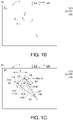
- FIG. 1A is an operation flowchart of a touch control method applied to a touch display apparatus 10 according to one embodiment of the present disclosure.
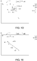
- FIGs. 1B to 1F are schematic diagrams of the screen images of the touch display apparatus 10 performing the touch control method as depicted in Figure 1A .
- the touch display apparatus 10 includes an image display area 11 and a touch operation system 12.
- the touch operation system 12 includes a touch panel 121 corresponding to the image display area 11 and a data processing unit 122 that executes the touch control method shown in FIG. 1A .
- the touch display apparatus 10 can be (but not limited to) a smart phone, a tablet computer, a laptop computer, a personal digital assistant (PDA) or a display panel built in a portable electronic device; also, it can be a built-in touch display panel of a car electronic device or an aircraft or other means of transportation; or it can be a touch display panel of a fixed or movable indoor or outdoor billboard.
- the image display area 11 does not overlap with the touch panel 121, however these two can have coordinates corresponding to each other. For example, the two have coordinates that map to each other.
- the touch panel 121 may be directly attached to the top of the display area 11.
- the data processing unit 122 may be (but not limited to) a logic circuit built in the touch display apparatus 10, such as a general-purpose processor, special-purpose application circuitry, or a combination of these two, and may be electrically connected to the image display area 11 and the touch electrodes and/or the control chip (not shown) of the touch panel 121 respectively (but not limited to this regard).
- the data processing unit 122 may be any device with computing capabilities including (but not limited to) at least one of a system chip (SOC), a field programmable gate array (FPGA) chip, a complex programmable logic device (CPLD), a microprocessor, a central processing unit (CPU), other hardware components, software components, firmware components and a combination thereof (not shown).
- the touch control method includes steps as follows: Firstly, a plurality of contact points being touched on the touch panel 121 at a certain time are identified (see step 101 in FIG. 1A ).
- the plurality of contact points being touched on the touch panel 121 can be detected by measuring changes in capacitance, resistance, optics, sound energy, images, or other physical quantities obtained from different positions in the touch panel 121, according to different types of the touch panel 121 (e.g., capacitive touch panel, infrared touch panel, ultrasonic touch panel, resistive touch panel, electromagnetic touch panel, image sensor touch panel... Etc.).
- the touch panel 121 may be a capacitive touch panel, and it can be determined that there are 6 contact points a, b, c, d, e, and f being touched on the touch panel 121 according to the capacitance obtained by directly sensing the touch electrodes at different positions of the touch panel 121. The sensing data is then transmitted to the data processing unit 122 for logical operation.
- a plurality of distances between each two of the plurality of contact points are obtained (see step 102 in FIG. 1A ).
- a plurality of distances between each two of the 6 contact points a, b, c, d, e, and f are obtained. As shown in FIG.
- the distance between contact points c and f is h1; the distance between contact points a and e is h2; the distance between contact points e and f is h3; the distance between contact points a and f is h4; the distance between contact points b and f is h5; the distance between contact points b and c is h6; the distance between contact points d and f is h7; the contact point c and d is h8; the distance between contact points a and d is h9; the distance between contact points b and d is h10; the distance between contact points a and b
- the distance is h11; the distance between contact points a and c is h12; the distance between contact points e and c is h13; the distance between contact points e and d is h14; the distance between contact points e and b is h15.
- a largest distance Max h smaller than a preset distance D is select from the plurality of distances h1-h15 (see step 103 in FIG. 1A ).
- a preset distance D For example, in the present embodiment, an average palm width of an adult can be used as the preset distance D, which is pre-input into the database 125 of the touch operating system 12.
- the largest distance Max h meeting the above condition can be determined by the logical operations that is performed by the data processing unit 122 based on the pre-input data of the database 125 and the sensing data obtained from the touch panel 121.
- the lengths of the distances h7, h8, h9, h10, h12, h13, and h14 are all greater than the preset distance D; while the distances h2, h3, h4, h5, h6, h11 and h15 are less than the preset distance D, and the largest distance Max h that meets the condition of less than the preset distance D (Max h ⁇ D) is the distance h1 between the contact points c and f.
- a first contact points cluster C11 among the plurality of contact points a, b, c, e and f, that falls into a first circular area S11 formed by two ends (the contact points c and f) of the largest distance Max h, are recognized as belonging to a first touch point P11(see step 104 in FIG. 1A ).
- the first circular area S11 may be a circular area formed on the touch panel 121 using the largest distance Max h (spacing h1) as the diameter, and using the midpoint between the two ends (between the contact points c and f) as the center.
- the first contact points cluster C11 composed of contact points b, c, and f falls within the first circular area S11, and the three can be determined as belonging to the first touch point P11.
- these three contact points b, c, and f may be within the palm width of the same person, so they are recognized as belonging to the first touch point P11.
- the step of determining the first coordinate includes forming a first polygon (such as, the triangle ⁇ bcf) by the contact points b, c, and f of the first contact points cluster C11 and calculating the center of gravity coordinate of the first polygon (such as, the triangle ⁇ bcf) to take it as the first coordinate of the first touch point P11.
- a first polygon such as, the triangle ⁇ bcf
- the center of gravity coordinate of the first polygon such as, the triangle ⁇ bcf
- the method for determining the first touch point P1 is not limited to this regard.
- the step of determining the first touch point P11' includes calculating the midpoint coordinate of the two end points (ie, the contact points c and f) of the largest distance Max h (ie, the distance h1) to take it as the first coordinate of the first touch point P11' (as shown in FIG. 1D ).
- a second largest distance smaller than the preset distance D is selected from the rest of the plurality of distances h2, h9 and h14 (see step 106 in FIG. 1A ).
- the distances h9 and h14 are both greater than the preset distance D; while only the distance h2 remains meeting the conditions of both less than the preset distance D and the distance h1 (h2 ⁇ h1 ⁇ D), as shown in FIG. 1E . Therefore, the distance h2 is selected as the second largest distance.
- a second contact points cluster C12 among the remaining of the plurality of contact points (including the contact points a, b, and e), that falls into a second circular area S12 formed by two ends (the contact points a and e) of the second largest distance (i.e. the distance h2), is recognized as a second touch point P12 (see step 107 in FIG. 1A ).
- the second circular area S12 may be a circular area formed on the touch panel 121 using the second largest distance (i.e. the distance h2) as the diameter and using the midpoint between the contact points a and e as the center. Only the contact points a and e fall within the second circular area S12, and the second contact points cluster C12 composed of contact points a and e can be determined as belonging to the second touch point P12.
- a second coordinate of the second touch point P12 is obtained (see step 108 in FIG. 1A ), wherein the method of determining the second coordinate of the second touch point P12 is similar to that of determining the first coordinate of the first touch point P11 (as shown in step 105).
- the second coordinate of the second touch point P12 can be the midpoint coordinate of the two end points (i.e. the contact points a and e) of the second largest distance (i.e. the distance h2) (as shown in FIG.1F ).
- step 109 in FIG. 1A Thereafter, check whether there are any remaining contact points (see step 109 in FIG. 1A ). If there are remaining contact points, repeat the above steps 106 to 108, and divide the remaining contact points into multiple contact points clusters in the same way. And determine the representative coordinates of these contact points clusters. For example, in the present embodiment, after the contact points a and e are recognized as the second contact points cluster C12, only the contact point d is left to form a third contact points cluster C13. Therefore, the remaining contact point d can be regarded as the third touch point P13, and the coordinates of the contact point d can be directly used as the third coordinate of the third touch point P13.
- At least one data processing can be performed by the data processing unit 122 on at least one corresponding position of the image display area 11 according to at least one of the first coordinate, the second coordinate and the third coordinate of the first touch point P11, the second the touch point P12 and the third touch point P13.
- one single-touch can be performed by the data processing unit 122 on a position corresponding to the first coordinate, according to the coordinates of the first touch point P11, the second touch point P12 and the third touch point P13.
- one multi-touch operation can be performed by the data processing unit 122 on several positions of the image display area 11 corresponding to different coordinates, according to the coordinates of the first touch point P11, the second touch point P12 and the third touch point P13.
- FIG. 2 is a schematic diagram of the screen image of the touch display apparatus 10 performing the touch control method according to another embodiment of this specification.
- the touch control method shown in FIG. 2 is substantially similar to that shown in FIGs. 1B to 1F , except the forming of the first circular area S21.
- the way for forming the first circular area S21 is different from that for forming of the first circular area S11 depicted in FIG. 1D . Since the steps of identifying the contact points being touched on the touch panel 121 at a certain time (such as, step 101) and obtaining the plural distances between each two of the contact points (such as, step 102) are described in FIGs. 1B to 1C , so the details of these steps will not be repeated here.
- the largest distance Max h (Max h ⁇ D) that is smaller than the preset distance D is select among the plurality of distances h1-h15, and the contact points a, b, c, d, e, and f that falls within the first circular area S21 formed by the two end points of the largest distance Max h (i.e. the contact points c and f) in the touch panel 121 is recognized as the first contact points cluster C21.
- the first circular area S21 can be a circular area formed on the touch panel 121 using the largest distance Max h (i.e. the distance h1) as the diameter, and using the contact point c as the center.
- the first contact points cluster C21 composed of contact points b, c, and f falls within the first circular area S21, and the three can be determined as belonging to the first touch point P21.
- the first circular area S21' can be a circular area formed on the touch panel 121 using the largest distance Max h (i.e. the distance h1) as the diameter, and using the contact point f as the center.
- the first contact points cluster C21' composed of contact points a, b, c, f and e falls within the first circular area S21', and the five can be determined as belonging to the first touch point P21'.
- the number of contact points included in the first contact points clusters C21 and C21' may also be different.
- the circular area S21' covering the largest number of contact points can be selected to determine the first touch point P21'.
- the first contact points cluster C21' composed of contact points a, b, c, f, and e is selected; and the first contact points cluster C21 composed of contact points b, c, and f is discarded, whereby the first touch point P21' can be determined.
- the contact point d can be directly regarded as the third touch point P13, and the coordinates of the contact point d can be taken as the third coordinates of the third touch point P13.
- At least one data processing e.g. Inputting commands, activating electronic devices, and/or clicking or opening various menus of application functions, can be performed by the data processing unit 122 on at least one corresponding position of the image display area 11 according to at least one of the first coordinate, the second coordinate and the third coordinate of the first touch point P21', the second the touch point P12 and the third touch point P13.
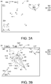
- FIGs. 3A to 3E are schematic diagrams of the screen images of the touch display apparatus 30 performing the touch control method according to yet another embodiment of this specification.
- the touch control method includes steps as follows:
- the contact points being touched on the touch panel 321 include not only the contact points a, b, c, d, e, and f as shown in Figure 1B , but also the contact points m, n, o, x, y, and z (as shown in FIG. 3A ).
- a plurality of distances between each two of the plurality of contact points are obtained.
- the detailed description of this step also has been disclosed in Figure 1C , it will not be repeated here.
- the distances h1-h15 between any two of the contact points a, b, c, e and f the distances h16, h17, and h18 between any two of the contact points x, y and z as wells as the distances h19, h20, and h21 between any two of the contact points m, n and o are shown in FIG. 3B .
- a largest tool distance dw1 which is greater than a preset distance D and smaller than a first tool width Dw1 is select from the plurality of distances h1-h21 (D ⁇ dw1 ⁇ Dw1).
- the largest width of the tool 323 can be used as the preset first tool width Dw1, which is input in advance into the built-in database 325 of the touch operating system 32 of the touch display apparatus 30, and logical operations are then perform ed by the data processing unit 322 of the touch display apparatus 30 according to the data in the database 325 and the data detected by the touch panel 321.
- the distance that meets the condition of the largest tool distance dw1 is the distance h17 between the contact points x and z.
- a first tool contact points cluster C31 among the plurality of contact points that falls into a third circular area S31 formed by two ends (the contact points x and z) of the largest tool distance are recognized as belonging to a first tool touch point Pt1.
- the third circular area S31 can be a circular area formed on the touch panel 321 using the largest tool distance dw1 (i.e. the distance h17) as the diameter and using the midpoint between the contact points x and z as the center, wherein the contact points x, y, and z fall within the third circular area S31. Therefore, the first tool contact points cluster C31 composed of contact points x, y, and z can be recognized belonging to the first tool touch point Pt1 (as shown in FIG. 3C ).
- the third circular regions S31' and S31" with different coverage can be formed in different ways.
- the third circular area S31' may be a circular area formed on the touch panel 321 using the largest tool distance dw1 (i.e. the distance h17) as the radius and using the contact point x as the center.
- the third circular area S31" may be a circular area formed on the touch panel 321 using the largest tool distance dw1 (i.e. the distance h17) as the radius and using the contact point z as the center.
- no matter which way is used to form the third circular area all the obtained first tool contact points clusters C31 are composed of three contact points x, y, and z. Therefore, it can be determined the first tool contact points cluster C31 composed of the contact points x, y, and z belongs to the first tool touch point Pt1.
- the step of determining the coordinate of the first tool touch point Pt1 includes forming a polygon (such as, the triangle ⁇ xyz ) by the contact points x, y, and z of the first tool contact points cluster C31 and calculating the center of gravity coordinate of the triangle ⁇ xyz to take it as the coordinate of the first tool touch point Pt1.
- the method for determining the coordinate of the first tool touch point Pt1 is not limited to this regard.
- the step of determining the coordinate of the first tool touch point Pt1' includes calculating the midpoint coordinate of the two end points (i.e. the contact points x and y) of the largest tool distance dw1 (i.e. the distance h17) to take it as the coordinate of the first tool touch point Pt1'.
- the information of the largest tool distance dw1 and/or the area of the third circular area S31, that is related to the tool 323 can be compared with the built-in database 325 of the touch display apparatus 30 by the data processing unit 322, and the matched content information 326 can be sent to and displayed on the image display area 31 of the touch display apparatus 30.
- the matched content information 326 resulted from the comparison of the largest tool distance dw1 and the built-in database 325 is a dinosaur pattern.
- the data processing unit 322 detects the touch points x, y, and z that match the condition of having the largest tool distance dw1 and/or the area of the third circular area S31 on the touch panel 321, the dinosaur pattern can be displayed on the position of the image display area 31 of the touch display apparatus 30 corresponding to the coordinates of the first tool touch point Pt1.
- a second largest tool distance dw2 greater than the preset distance D and smaller than a second tool width Dw2 of a tool 324 (D ⁇ dw2 ⁇ Dw2) is selected from the rest of the plurality of distances h1-h16 and h18-h21.
- the second tool width Dw2 of the tool 324 has also been pre-input in the database 325 of the data processing unit 322 for performing logical operations based on the data detected by the touch panel 321 by the data processing unit 322.
- FIG. 3D among the distances h1-h16 and h18-h21, mere the distance h21 between the contact points o and m meets the condition (D ⁇ dw2 ⁇ Dw2) of the second largest tool distance dw2.
- a second tool contact points cluster C12, among the remaining of the plurality of contact points, that falls into a fourth circular area S32 formed by two ends (the contact points m and o) of the second largest distance dw2 (i.e. the distance h21) is recognized as a second tool touch point Pt2.
- the fourth circular area S32 can be a circular area formed on the touch panel 321 using the second largest distance dw2 (i.e. the distance h21) as the diameter and using the midpoint between the contact points m and o.
- it can be the fourth circular area S32' formed on the touch panel 321 using the second largest distance dw2 (i.e.
- the distance h21 as the radius and using the contact point m as the center; or can be the fourth circular area S32" formed on the touch panel 321 using the second largest distance dw2 (i.e. the distance h21) as the radius and using the contact point o as the center.
- the second tool contact point cluster C32 composed of the contact points m, o, and n belongs to the second tool touch point Pt2 and covered by the tool 324 (as shown in FIG.3D ).
- the step of determining the coordinate of the second tool touch point Pt2 includes taking the center of gravity coordinate of the triangle ⁇ mon formed by the contact points m, o, and n of the second tool contact points cluster C32 as the coordinate of the second tool touch point Pt2; or taking the coordinate of the midpoint (not shown) between the two end points (i.e. the contact points m and o) of the second largest tool distance dw2 as the coordinate of the second tool touch point Pt2.
- the information of the second largest tool distance dw2 and/or the area of the fourth circular area S32, that is related to the tool 324 can be compared with the built-in database 325 of the touch display apparatus 30 by the data processing unit 322, and the matched content information 327 can be sent to and displayed on the image display area 31 of the touch display apparatus 30.
- the matched content information 327 resulted from the comparison of the second largest tool distance dw2 and the built-in database 325 is a pattern of English letters .
- the pattern of English letters can be displayed on the position of the image display area 31 of the touch display apparatus 30 corresponding to the coordinates of the second tool touch point Pt2.
- the embodiments of the disclosure provide a touch control method and a touch operation system applied to a touch display apparatus.
- a preset distance as a judgment standard to divides a plurality of contact points being touched on a touch area of the touch display apparatus at a certain time into several contact points clusters, and the representative coordinates of these contact points clusters can be obtained to serve as the available touch points for performing at least one data processing, such as inputting instructions, starting electronic devices, and/or clicking or opening various menus or functions including applications (APP); meanwhile the operations of the data processing can be displayed on the corresponding position of the display area of the touch display apparatus.
- APP applications
Landscapes
- Engineering & Computer Science (AREA)
- General Engineering & Computer Science (AREA)
- Theoretical Computer Science (AREA)
- Human Computer Interaction (AREA)
- Physics & Mathematics (AREA)
- General Physics & Mathematics (AREA)
- User Interface Of Digital Computer (AREA)
Applications Claiming Priority (1)
| Application Number | Priority Date | Filing Date | Title |
|---|---|---|---|
| CN202011061761.XA CN114327109B (zh) | 2020-09-30 | 2020-09-30 | 触控操作方法及触控操作系统 |
Publications (2)
| Publication Number | Publication Date |
|---|---|
| EP3979062A1 true EP3979062A1 (de) | 2022-04-06 |
| EP3979062B1 EP3979062B1 (de) | 2026-03-11 |
Family
ID=78134748
Family Applications (1)
| Application Number | Title | Priority Date | Filing Date |
|---|---|---|---|
| EP21199363.9A Active EP3979062B1 (de) | 2020-09-30 | 2021-09-28 | Berührungssteuerungsverfahren und berührungssteuerungssystem damit |
Country Status (3)
| Country | Link |
|---|---|
| US (1) | US11604578B2 (de) |
| EP (1) | EP3979062B1 (de) |
| CN (1) | CN114327109B (de) |
Citations (4)
| Publication number | Priority date | Publication date | Assignee | Title |
|---|---|---|---|---|
| US20130147771A1 (en) * | 2011-12-07 | 2013-06-13 | Elan Microelectronics Corporation | Method for prevention against remiss touch on a touchpad |
| US20130257748A1 (en) * | 2012-04-02 | 2013-10-03 | Anthony J. Ambrus | Touch sensitive user interface |
| EP2667294A2 (de) * | 2012-05-23 | 2013-11-27 | Kabushiki Kaisha Square Enix (also trading as Square Enix Co., Ltd.) | Informationsverarbeitungsvorrichtung, Verfahren zur Informationsverarbeitung und Spielvorrichtung |
| WO2015187319A1 (en) * | 2014-06-01 | 2015-12-10 | Intel Corporation | System and method for determining a number of users and their respective positions relative to a device |
Family Cites Families (17)
| Publication number | Priority date | Publication date | Assignee | Title |
|---|---|---|---|---|
| US7663607B2 (en) * | 2004-05-06 | 2010-02-16 | Apple Inc. | Multipoint touchscreen |
| TWM241746U (en) | 2003-08-22 | 2004-08-21 | Compal Electronics Inc | Touch-controlled input apparatus of electronic apparatus |
| TW200617753A (en) | 2006-01-20 | 2006-06-01 | E Lead Electronic Co Ltd | Composite cursor input device and input method thereof |
| TW200928905A (en) | 2007-12-26 | 2009-07-01 | E Lead Electronic Co Ltd | A method for controlling touch pad cursor |
| US9684521B2 (en) | 2010-01-26 | 2017-06-20 | Apple Inc. | Systems having discrete and continuous gesture recognizers |
| KR100997437B1 (ko) * | 2009-04-14 | 2010-11-30 | 에이디반도체(주) | 멀티터치 스크린에서의 펜 인식 장치 및 방법 |
| CN101593060B (zh) | 2009-07-06 | 2012-10-03 | 友达光电股份有限公司 | 触碰操作方法与电子装置的操作方法 |
| CA2771918C (en) * | 2009-08-25 | 2015-06-09 | Google Inc. | Direct manipulation gestures |
| KR101660842B1 (ko) * | 2009-11-05 | 2016-09-29 | 삼성전자주식회사 | 터치 입력 방법 및 그 장치 |
| US20110239163A1 (en) * | 2009-12-04 | 2011-09-29 | Daisuke Mochizuki | Display screen control method, graphical user interface, information processing apparatus, information processing method, and program |
| KR101706237B1 (ko) * | 2010-11-26 | 2017-02-14 | 엘지디스플레이 주식회사 | 터치스크린 표시장치 및 이의 터치 판단방법 |
| TWI585671B (zh) | 2013-01-04 | 2017-06-01 | 三貝德數位文創股份有限公司 | 多點式觸控物辨識系統 |
| CN103164081B (zh) * | 2013-02-22 | 2016-08-03 | 苏州佳世达电通有限公司 | 触控装置及其触控点侦测方法 |
| KR20140135884A (ko) * | 2013-05-16 | 2014-11-27 | 삼성전자주식회사 | 디스플레이 장치 및 그 제어방법 |
| CN105808081A (zh) * | 2014-12-29 | 2016-07-27 | 鸿合科技有限公司 | 一种利用手势快速删除多个对象的方法和装置 |
| CN205121529U (zh) * | 2015-07-28 | 2016-03-30 | 李睿 | 一种带有触控屏的电脑终端用防误触装置 |
| TWI629615B (zh) | 2017-04-28 | 2018-07-11 | 明基電通股份有限公司 | 具有顯示子母畫面能力的顯示系統 |
-
2020
- 2020-09-30 CN CN202011061761.XA patent/CN114327109B/zh active Active
-
2021
- 2021-08-02 US US17/391,151 patent/US11604578B2/en active Active
- 2021-09-28 EP EP21199363.9A patent/EP3979062B1/de active Active
Patent Citations (4)
| Publication number | Priority date | Publication date | Assignee | Title |
|---|---|---|---|---|
| US20130147771A1 (en) * | 2011-12-07 | 2013-06-13 | Elan Microelectronics Corporation | Method for prevention against remiss touch on a touchpad |
| US20130257748A1 (en) * | 2012-04-02 | 2013-10-03 | Anthony J. Ambrus | Touch sensitive user interface |
| EP2667294A2 (de) * | 2012-05-23 | 2013-11-27 | Kabushiki Kaisha Square Enix (also trading as Square Enix Co., Ltd.) | Informationsverarbeitungsvorrichtung, Verfahren zur Informationsverarbeitung und Spielvorrichtung |
| WO2015187319A1 (en) * | 2014-06-01 | 2015-12-10 | Intel Corporation | System and method for determining a number of users and their respective positions relative to a device |
Non-Patent Citations (1)
| Title |
|---|
| SUNDAR MURUGAPPAN ET AL: "Extended multitouch", PROCEEDINGS OF THE 25TH ANNUAL ACM SYMPOSIUM ON USER INTERFACE SOFTWARE AND TECHNOLOGY, UIST '12, 10 October 2012 (2012-10-10), New York, New York, USA, pages 487, XP055203410, ISBN: 978-1-45-031580-7, DOI: 10.1145/2380116.2380177 * |
Also Published As
| Publication number | Publication date |
|---|---|
| US11604578B2 (en) | 2023-03-14 |
| EP3979062B1 (de) | 2026-03-11 |
| CN114327109A (zh) | 2022-04-12 |
| US20220100365A1 (en) | 2022-03-31 |
| CN114327109B (zh) | 2023-12-19 |
Similar Documents
| Publication | Publication Date | Title |
|---|---|---|
| CN105824559B (zh) | 一种误触识别及处理方法和电子设备 | |
| US8432301B2 (en) | Gesture-enabled keyboard and associated apparatus and computer-readable storage medium | |
| US9104308B2 (en) | Multi-touch finger registration and its applications | |
| US9367235B2 (en) | Detecting and interpreting real-world and security gestures on touch and hover sensitive devices | |
| US8941600B2 (en) | Apparatus for providing touch feedback for user input to a touch sensitive surface | |
| US8816964B2 (en) | Sensor-augmented, gesture-enabled keyboard and associated apparatus and computer-readable storage medium | |
| CN107741824B (zh) | 对可重定位触摸表面上的姿态朝向的检测 | |
| US20090243998A1 (en) | Apparatus, method and computer program product for providing an input gesture indicator | |
| CN104731497B (zh) | 管理防误触的多个触摸源的设备和方法 | |
| CN101636711A (zh) | 利用多点感测设备作姿态 | |
| WO2007121676A1 (en) | Method and device for controlling information display output and input device | |
| CN106445369B (zh) | 一种输入的方法和装置 | |
| CN103164067A (zh) | 判断触摸输入的方法及电子设备 | |
| CN106599246B (zh) | 一种显示内容的拦截方法、移动终端及控制服务器 | |
| CN103197790B (zh) | 可携式电子装置及触控感测方法 | |
| US9645729B2 (en) | Precise object selection in touch sensing systems | |
| CN106406738A (zh) | 一种键盘的按键内容信息的输入方法及移动终端 | |
| US20160026309A1 (en) | Controller | |
| CN105786373B (zh) | 一种触控轨迹显示方法及电子设备 | |
| US20130113728A1 (en) | Single-point-multi-finger gestures for touch panel | |
| EP3979062B1 (de) | Berührungssteuerungsverfahren und berührungssteuerungssystem damit | |
| CN103713840B (zh) | 可携式装置及其按键点击范围调整方法 | |
| TWI742894B (zh) | 觸控操作方法及其觸控操作系統 | |
| CN105320327A (zh) | 手持式电子装置及其触控外盖 | |
| CN105446520B (zh) | 无挡单手多指触控的手持式电子装置、触控外盖及计算机执行的方法 |
Legal Events
| Date | Code | Title | Description |
|---|---|---|---|
| PUAI | Public reference made under article 153(3) epc to a published international application that has entered the european phase |
Free format text: ORIGINAL CODE: 0009012 |
|
| STAA | Information on the status of an ep patent application or granted ep patent |
Free format text: STATUS: REQUEST FOR EXAMINATION WAS MADE |
|
| 17P | Request for examination filed |
Effective date: 20210928 |
|
| AK | Designated contracting states |
Kind code of ref document: A1 Designated state(s): AL AT BE BG CH CY CZ DE DK EE ES FI FR GB GR HR HU IE IS IT LI LT LU LV MC MK MT NL NO PL PT RO RS SE SI SK SM TR |
|
| RBV | Designated contracting states (corrected) |
Designated state(s): AL AT BE BG CH CY CZ DE DK EE ES FI FR GB GR HR HU IE IS IT LI LT LU LV MC MK MT NL NO PL PT RO RS SE SI SK SM TR |
|
| P01 | Opt-out of the competence of the unified patent court (upc) registered |
Effective date: 20230602 |
|
| STAA | Information on the status of an ep patent application or granted ep patent |
Free format text: STATUS: EXAMINATION IS IN PROGRESS |
|
| 17Q | First examination report despatched |
Effective date: 20240822 |
|
| GRAP | Despatch of communication of intention to grant a patent |
Free format text: ORIGINAL CODE: EPIDOSNIGR1 |
|
| STAA | Information on the status of an ep patent application or granted ep patent |
Free format text: STATUS: GRANT OF PATENT IS INTENDED |
|
| INTG | Intention to grant announced |
Effective date: 20251009 |
|
| GRAS | Grant fee paid |
Free format text: ORIGINAL CODE: EPIDOSNIGR3 |
|
| GRAA | (expected) grant |
Free format text: ORIGINAL CODE: 0009210 |
|
| STAA | Information on the status of an ep patent application or granted ep patent |
Free format text: STATUS: THE PATENT HAS BEEN GRANTED |
|
| AK | Designated contracting states |
Kind code of ref document: B1 Designated state(s): AL AT BE BG CH CY CZ DE DK EE ES FI FR GB GR HR HU IE IS IT LI LT LU LV MC MK MT NL NO PL PT RO RS SE SI SK SM TR |
|
| REG | Reference to a national code |
Ref country code: CH Ref legal event code: F10 Free format text: ST27 STATUS EVENT CODE: U-0-0-F10-F00 (AS PROVIDED BY THE NATIONAL OFFICE) Effective date: 20260311 Ref country code: GB Ref legal event code: FG4D |
|
| REG | Reference to a national code |
Ref country code: DE Ref legal event code: R096 Ref document number: 602021049619 Country of ref document: DE |
|
| REG | Reference to a national code |
Ref country code: IE Ref legal event code: FG4D |