EP3978931A1 - Method for introducing liquid into wells - Google Patents
Method for introducing liquid into wells Download PDFInfo
- Publication number
- EP3978931A1 EP3978931A1 EP20813025.2A EP20813025A EP3978931A1 EP 3978931 A1 EP3978931 A1 EP 3978931A1 EP 20813025 A EP20813025 A EP 20813025A EP 3978931 A1 EP3978931 A1 EP 3978931A1
- Authority
- EP
- European Patent Office
- Prior art keywords
- liquid
- wells
- image
- sealing solution
- fluidic device
- Prior art date
- Legal status (The legal status is an assumption and is not a legal conclusion. Google has not performed a legal analysis and makes no representation as to the accuracy of the status listed.)
- Pending
Links
Images






Classifications
-
- B—PERFORMING OPERATIONS; TRANSPORTING
- B01—PHYSICAL OR CHEMICAL PROCESSES OR APPARATUS IN GENERAL
- B01L—CHEMICAL OR PHYSICAL LABORATORY APPARATUS FOR GENERAL USE
- B01L3/00—Containers or dishes for laboratory use, e.g. laboratory glassware; Droppers
- B01L3/50—Containers for the purpose of retaining a material to be analysed, e.g. test tubes
- B01L3/502—Containers for the purpose of retaining a material to be analysed, e.g. test tubes with fluid transport, e.g. in multi-compartment structures
- B01L3/5027—Containers for the purpose of retaining a material to be analysed, e.g. test tubes with fluid transport, e.g. in multi-compartment structures by integrated microfluidic structures, i.e. dimensions of channels and chambers are such that surface tension forces are important, e.g. lab-on-a-chip
- B01L3/502715—Containers for the purpose of retaining a material to be analysed, e.g. test tubes with fluid transport, e.g. in multi-compartment structures by integrated microfluidic structures, i.e. dimensions of channels and chambers are such that surface tension forces are important, e.g. lab-on-a-chip characterised by interfacing components, e.g. fluidic, electrical, optical or mechanical interfaces
-
- G—PHYSICS
- G01—MEASURING; TESTING
- G01N—INVESTIGATING OR ANALYSING MATERIALS BY DETERMINING THEIR CHEMICAL OR PHYSICAL PROPERTIES
- G01N35/00—Automatic analysis not limited to methods or materials provided for in any single one of groups G01N1/00 - G01N33/00; Handling materials therefor
- G01N35/02—Automatic analysis not limited to methods or materials provided for in any single one of groups G01N1/00 - G01N33/00; Handling materials therefor using a plurality of sample containers moved by a conveyor system past one or more treatment or analysis stations
-
- B—PERFORMING OPERATIONS; TRANSPORTING
- B01—PHYSICAL OR CHEMICAL PROCESSES OR APPARATUS IN GENERAL
- B01L—CHEMICAL OR PHYSICAL LABORATORY APPARATUS FOR GENERAL USE
- B01L3/00—Containers or dishes for laboratory use, e.g. laboratory glassware; Droppers
- B01L3/50—Containers for the purpose of retaining a material to be analysed, e.g. test tubes
- B01L3/502—Containers for the purpose of retaining a material to be analysed, e.g. test tubes with fluid transport, e.g. in multi-compartment structures
- B01L3/5027—Containers for the purpose of retaining a material to be analysed, e.g. test tubes with fluid transport, e.g. in multi-compartment structures by integrated microfluidic structures, i.e. dimensions of channels and chambers are such that surface tension forces are important, e.g. lab-on-a-chip
- B01L3/502769—Containers for the purpose of retaining a material to be analysed, e.g. test tubes with fluid transport, e.g. in multi-compartment structures by integrated microfluidic structures, i.e. dimensions of channels and chambers are such that surface tension forces are important, e.g. lab-on-a-chip characterised by multiphase flow arrangements
-
- B—PERFORMING OPERATIONS; TRANSPORTING
- B01—PHYSICAL OR CHEMICAL PROCESSES OR APPARATUS IN GENERAL
- B01L—CHEMICAL OR PHYSICAL LABORATORY APPARATUS FOR GENERAL USE
- B01L3/00—Containers or dishes for laboratory use, e.g. laboratory glassware; Droppers
- B01L3/50—Containers for the purpose of retaining a material to be analysed, e.g. test tubes
- B01L3/502—Containers for the purpose of retaining a material to be analysed, e.g. test tubes with fluid transport, e.g. in multi-compartment structures
- B01L3/5027—Containers for the purpose of retaining a material to be analysed, e.g. test tubes with fluid transport, e.g. in multi-compartment structures by integrated microfluidic structures, i.e. dimensions of channels and chambers are such that surface tension forces are important, e.g. lab-on-a-chip
- B01L3/502707—Containers for the purpose of retaining a material to be analysed, e.g. test tubes with fluid transport, e.g. in multi-compartment structures by integrated microfluidic structures, i.e. dimensions of channels and chambers are such that surface tension forces are important, e.g. lab-on-a-chip characterised by the manufacture of the container or its components
-
- G—PHYSICS
- G01—MEASURING; TESTING
- G01N—INVESTIGATING OR ANALYSING MATERIALS BY DETERMINING THEIR CHEMICAL OR PHYSICAL PROPERTIES
- G01N37/00—Details not covered by any other group of this subclass
-
- B—PERFORMING OPERATIONS; TRANSPORTING
- B01—PHYSICAL OR CHEMICAL PROCESSES OR APPARATUS IN GENERAL
- B01L—CHEMICAL OR PHYSICAL LABORATORY APPARATUS FOR GENERAL USE
- B01L2200/00—Solutions for specific problems relating to chemical or physical laboratory apparatus
- B01L2200/06—Fluid handling related problems
- B01L2200/0689—Sealing
-
- B—PERFORMING OPERATIONS; TRANSPORTING
- B01—PHYSICAL OR CHEMICAL PROCESSES OR APPARATUS IN GENERAL
- B01L—CHEMICAL OR PHYSICAL LABORATORY APPARATUS FOR GENERAL USE
- B01L2200/00—Solutions for specific problems relating to chemical or physical laboratory apparatus
- B01L2200/12—Specific details about manufacturing devices
-
- B—PERFORMING OPERATIONS; TRANSPORTING
- B01—PHYSICAL OR CHEMICAL PROCESSES OR APPARATUS IN GENERAL
- B01L—CHEMICAL OR PHYSICAL LABORATORY APPARATUS FOR GENERAL USE
- B01L2200/00—Solutions for specific problems relating to chemical or physical laboratory apparatus
- B01L2200/16—Reagents, handling or storing thereof
-
- B—PERFORMING OPERATIONS; TRANSPORTING
- B01—PHYSICAL OR CHEMICAL PROCESSES OR APPARATUS IN GENERAL
- B01L—CHEMICAL OR PHYSICAL LABORATORY APPARATUS FOR GENERAL USE
- B01L2300/00—Additional constructional details
- B01L2300/06—Auxiliary integrated devices, integrated components
- B01L2300/0627—Sensor or part of a sensor is integrated
- B01L2300/0663—Whole sensors
-
- B—PERFORMING OPERATIONS; TRANSPORTING
- B01—PHYSICAL OR CHEMICAL PROCESSES OR APPARATUS IN GENERAL
- B01L—CHEMICAL OR PHYSICAL LABORATORY APPARATUS FOR GENERAL USE
- B01L2300/00—Additional constructional details
- B01L2300/08—Geometry, shape and general structure
- B01L2300/0809—Geometry, shape and general structure rectangular shaped
- B01L2300/0829—Multi-well plates; Microtitration plates
-
- B—PERFORMING OPERATIONS; TRANSPORTING
- B01—PHYSICAL OR CHEMICAL PROCESSES OR APPARATUS IN GENERAL
- B01L—CHEMICAL OR PHYSICAL LABORATORY APPARATUS FOR GENERAL USE
- B01L2300/00—Additional constructional details
- B01L2300/08—Geometry, shape and general structure
- B01L2300/0861—Configuration of multiple channels and/or chambers in a single devices
- B01L2300/0877—Flow chambers
-
- C—CHEMISTRY; METALLURGY
- C12—BIOCHEMISTRY; BEER; SPIRITS; WINE; VINEGAR; MICROBIOLOGY; ENZYMOLOGY; MUTATION OR GENETIC ENGINEERING
- C12M—APPARATUS FOR ENZYMOLOGY OR MICROBIOLOGY; APPARATUS FOR CULTURING MICROORGANISMS FOR PRODUCING BIOMASS, FOR GROWING CELLS OR FOR OBTAINING FERMENTATION OR METABOLIC PRODUCTS, i.e. BIOREACTORS OR FERMENTERS
- C12M23/00—Constructional details, e.g. recesses, hinges
- C12M23/02—Form or structure of the vessel
- C12M23/12—Well or multiwell plates
Definitions
- the present invention relates to a method of introducing liquid into wells.
- ELISA enzyme-linked immunosorbent assay
- PTL 1, PTL 2, and NPL 1 disclose techniques for performing an enzyme reaction in a large number of micro compartments as techniques for accurately detecting a target molecule. These techniques are called digital quantification.
- a sample solution is divided into a large number of micro compartments. Then, a signal from each micro compartment is binarized, and the number of target molecules is measured by determining only whether the target molecule is present or not.
- the digital quantification can significantly improve the detection sensitivity and the quantitativeness compared with conventional methods such as ELISA, real-time PCR method and the like.
- the digital quantification technology is widely used not only for the above diagnostic application, but also for an application in which a large number of target molecules are separated from each other and analyzed.
- the digital quantification technology is used for functional analysis of transmembrane proteins.
- An object of the present invention is to provide a technique for replacing a liquid in the individually sealed micro compartments.
- the present invention includes the following aspects.
- An embodiment of the present invention provides a method of introducing a second liquid into wells in a fluidic device which includes a substrate and a plurality of the wells, the wells being open to a first surface of the substrate and accommodating a first liquid containing a surfactant, and openings of the wells being sealed with a first sealing solution supplied onto the first surface, the method including: introducing the second liquid onto the first surface, whereby the first sealing solution is replaced with the second liquid.
- liquid in the individually sealed micro compartments can be replaced. Accordingly, in digital quantification technology, for example, after an analysis result is obtained using a reaction reagent contained in a first liquid introduced into the micro compartments, the liquid in the micro compartments is replaced with a second liquid so that another analysis can be performed using a reaction reagent contained in the second liquid.
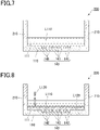
- Fig. 1 is a schematic cross-sectional view illustrating an example of a fluidic device.
- a fluidic device 100 includes a substrate 110, and a cover member 120 disposed to face a first surface 111 of the substrate 110.
- the cover member 120 has a projection 121.
- the distal end of the projection 121 is in contact with the substrate 110.
- a plurality of wells 141, forming a well array 140 are integrally formed on the first surface 111 of the substrate 110.
- the first surface 111 faces the cover member 120.
- the cover member 120 may be welded or bonded to the substrate 110.
- the wells 141 are open to a surface of the substrate 110. Although the shape, size, and arrangement of the wells 141 are not specifically limited, it is preferred that one target molecule is introduced into each well 141.
- the wells 141 are preferably microwells having a small volume. For example, each well 141 may have a volume of approximately 10 fL to 100 pL.
- the plurality of wells 141 having the same shape and the same size constitute the well array 140.
- the expression "the same shape and the same size" refers to the shape and the volume being the same to the extent required for digital quantification, and a variation approximately within a manufacturing error may be accepted.
- the well 141 may have a diameter of, for example, approximately 1 to 30 ⁇ m.
- the well 141 may have a depth of, for example, approximately 1 to 30 ⁇ m.
- the arrangement of the wells 141 is not specifically limited.
- the wells 141 may be arranged in a triangular lattice or a square lattice shape, or randomly arranged.
- the flow path 130 functions as a path for supplying a first liquid, a first sealing solution, a second liquid, and a second sealing solution, which will be described later. That is, the first liquid, the first sealing solution, the second liquid, and the second sealing solution are introduced into the fluidic device 100 through the flow path 130.
- the height of the flow path 130 (that is, a distance between the first surface 111 of the substrate 110 and a surface of the cover member 120 facing the substrate 110) may be, for example, 100 ⁇ m or less.
- the projection 121 may be molded integrally with the cover member 120.
- the cover member 120 can be formed as a plate shape having the projection 121 by molding a thermoplastic resin fluid using a mold.
- an inlet port 122 and a discharge port 123 for a reagent may also be formed on the cover member 120.
- the cover member 120 When the cover member 120 includes the projection 121, the cover member 120 and the substrate 110 are stacked with the projection 121 being in contact with the surface 111 of the substrate 110 to which the wells 141 are open. A space thus formed between the cover member 120 and the substrate 110 is provided as the flow path 130.
- the cover member 120 and the substrate 110 may be welded to each other by laser welding or the like.
- FIG. 7 is a schematic cross-sectional view illustrating an example of a fluidic device.
- a fluidic device 200 includes the substrate 110 and a wall member 210.
- the well array 140 is molded integrally with the substrate 110 on the first surface 111 of the substrate 110.
- the well array 140 includes a plurality of wells 141.
- the fluidic device 200 differs from the above fluidic device 100 mainly in that it does not include the cover member 120. Accordingly, the fluidic device 200 does not include a flow path.
- the cover member 120 and the projection 121 are integrally molded.
- the cover member 120 and the projection 121 may also be molded as separate members.
- the well array 140 is molded integrally with the substrate 110 on the first surface 111 of the substrate 110.
- the well array may not necessarily be molded integrally with the substrate 110.
- a well array 140 molded separately from the fluidic device may be disposed on the substrate 110 of the fluidic device.
- a resin layer may be laminated on a surface of the substrate 110 to form a well array on the resin layer by etching or the like.
- the substrate 110 is formed using a resin, for example.
- a resin for example.
- the type of the resin is not specifically limited, it is preferred that the resin is resistant to the first liquid, the second liquid, and the sealing solutions. Further, when a signal to be detected is fluorescence, it is preferred that the resin has low autofluorescence.
- the resin may include, but are not limited to, a cycloolefin polymer, a cycloolefin copolymer, silicone, polypropylene, polycarbonate, polystyrene, polyethylene, polyvinyl acetate, a fluororesin, an amorphous fluororesin, and the like.
- a plurality of wells 141 may be formed on the first surface 111 located on one side of the substrate 110 in the thickness direction.
- the wells may be formed using a resin by injection molding, thermal imprinting, optical imprinting, or the like.
- a fluororesin may be laminated on the substrate 110 to form a well array on the fluororesin by etching or the like.
- CYTOP registered trademark
- As the fluororesin for example, CYTOP (registered trademark) (Asahi Glass Co., Ltd.) or the like may be used.
- the material of the cover member 120 is preferably a resin having low autofluorescence, and may be, for example, a thermoplastic resin such as a cycloolefin polymer or a cycloolefin copolymer.
- the cover member 120 may also be formed of a material that does not transmit light of a wavelength near the wavelength detected in fluorescence observation of a signal, or a material that only partially transmits light.
- the cover member 120 may be formed of a thermoplastic resin to which carbon or metal particles are added.
- a method of the present embodiment is a method of introducing a second liquid into wells in a fluidic device which includes a substrate and a plurality of the wells, the wells being open to a first surface of the substrate and accommodating a first liquid containing a surfactant, and openings of the wells being sealed with a first sealing solution supplied onto the first surface, the method including: introducing the second liquid onto the first surface, whereby the first sealing solution is replaced with the second liquid.
- a first liquid L110 is introduced through the inlet port 122 of the fluidic device 100 into the flow path 130.
- the first liquid L110 includes, for example, biological samples or environmental samples.
- biological samples may include, but are not limited to, serum, plasma, urine, cell culture solution, and the like.
- environmental samples may include river water, factory wastewater, and the like.
- the biological samples and environmental samples may contain target molecules to be detected. Alternatively, the biological samples and environmental samples may not contain target molecules to be detected. Examples of the target molecules include DNA, RNA, proteins, viruses, cells, specific compounds, and the like.
- the RNA may be miRNA, mRNA, or the like.
- the cells may be bacteria, yeast, animal cells, plant cells, insect cells, or the like.
- the first liquid L110 may contain a reaction reagent for detecting a target molecule.
- the reaction reagent include buffer substances, enzymes, substrates, antibodies, antibody fragments, and the like.
- the enzyme is selected according to the content of biochemical reaction.
- the target molecule is a nucleic acid
- the enzyme is selected to perform a biochemical reaction such as an enzyme reaction with a template nucleic acid associated with the target molecule.
- the biochemical reaction to the template nucleic acid is, for example, a reaction in which signal amplification occurs in the presence of a template nucleic acid.
- the reaction reagent is selected according to the detection reaction to be employed.
- the detection reaction include an invasive cleavage assay (ICA) method, loop-mediated isothermal amplification (LAMP) method (registered trademark), 5' ⁇ 3' nuclease method (TaqMan (registered trademark)), fluorescent probe method, and the like.
- ICA invasive cleavage assay
- LAMP loop-mediated isothermal amplification
- TaqMan 5' ⁇ 3' nuclease method
- fluorescent probe method and the like.
- the first liquid L110 contains a surfactant.
- the concentration of the surfactant is preferably 0.001 v/v% or more and 1.0 v/v% or less relative to the total volume of the first liquid L110, more preferably 0.005 v/v% or more and 0.5 v/v% or less, and still more preferably 0.01 v/v% or more and 0.1 v/v% or less.
- concentration of the surfactant is 0.001 v/v% or more relative to the total volume of the first liquid L110, replacement with the second liquid L410 can be easily performed.
- the concentration of the surfactant is 1.0 v/v% or less relative to the total volume of the first liquid L110, the influence on the reaction in the subsequent detection of target molecule can be minimized.
- the first liquid L110 supplied into the flow path 130 is accommodated in the wells 141. Accordingly, the reaction reagent, the surfactant, and target molecules, if present, are introduced into the wells 141.
- the number of target molecules introduced into each well 141 is not specifically limited, it is preferred that 1 or less, that is, 0 or 1 target molecule is introduced into each well 141. Accordingly, the target molecule can be detected in units of one piece, that is, digital quantification can be performed.
- the target molecule is not necessarily introduced into every well 141 of the well array 140.
- a means for introducing target molecules into the wells 141 is not specifically limited, and an appropriate means for the selected target molecule can be used.
- target molecules may precipitate by their own weight in the fluidic device (specifically, in the flow path), and be distributed into the wells 141.
- a carrier that is, capture substance
- the target molecules that are unlikely to precipitate by their own weight can be bound to the capture substances when they are supplied.
- the capture substances can be immobilized to the wells 141 in advance so as to capture target molecules that are supplied. Accordingly, the target molecules can be introduced into the wells at improved efficiency.
- the step of binding the capture substances to the target molecules can be performed at any time.
- the step may be performed by bringing the target molecules and the capture substances into contact with each other in a sample tube before the target molecules are introduced into the wells 141.
- the target molecules may be introduced into the wells after the capture substances are introduced into the wells 141 so that the capture substances and the target molecules are in contact with other in the wells.
- the capture substance is a substance capable of capturing target molecules.
- the capture substance may be, for example, a conjugate of a solid phase and a specific binding substance for the target molecule.
- the solid phase may be particles, films, substrates, or the like.
- the specific binding substance for the target molecule may be one or more. For example, three, four, or five or more specific binding substances may be used.
- the particles are not specifically limited, and may be polymer particles, magnetic particles, glass particles, or the like.
- the particles are subjected to a surface treatment in order to avoid nonspecific adsorption.
- particles having a functional group such as a carboxyl group on the surface are preferred. More specifically, a product "Magnosphere LC300" manufactured by JSR Corporation or the like can be used as the particles.
- a cell to which the virus can be attached (that is, a cell having a virus receptor) can be used as the capture substance.
- Examples of the specific binding substance in the capture substance include antibodies, antibody fragments, aptamers, and the like.
- the antibody fragment include Fab, F(ab') 2 , Fab', single chain antibodies (scFv), disulfide stabilized antibodies (dsFv), dimeric V region fragments (Diabody), peptides including CDR, and the like.
- the antibody may be a monoclonal antibody or a polyclonal antibody. Alternatively, the antibody may be a commercially available antibody.
- the specific binding substance may be a lectin.
- the specific binding substance may be a substance that binds to the lipid membrane.
- the substance that binds to lipid membrane include hydrocarbons such as hexanediol and membrane proteins such as transmembrane proteins.
- the membrane proteins may be, for example, ⁇ -hemolysin.
- the method of immobilizing the specific binding substance to the solid phase is not limited, and it is possible to use a method using physical adsorption, a method using chemical bonding, a method using avidin-biotin binding, a method of using a bond between protein G or protein A to an antibody, or the like.
- a method using physical adsorption there is a method of immobilizing a specific binding substance to the particle surface by hydrophobic interaction or electrostatic interaction.
- As the method by chemical bonding there is a method using a crosslinking agent.
- the carboxyl group of the specific binding substance is allowed to react with a crosslinking agent to obtain an active ester, and then the hydroxyl group and the ester group are allowed to react, whereby the specific binding substance can be immobilized to the particle surface. It is also preferable to provide a spacer between the specific binding substance and the particle surface so as not to inhibit the recognition ability of the specific binding substance to recognize the target molecule.
- each well 141 is preferably configured to accommodate 0 or 1 capture substance. Thus, digital quantification can be performed.
- a first sealing solution L120 is introduced through the inlet port 122 into the flow path 130.
- the first sealing solution is preferably an oily solution, and more preferably an oil.
- the oil include fluorine-based oil, silicone-based oil, hydrocarbon-based oil, and a mixture thereof. More specifically, oil manufactured by Sigma under the product name "FC-40" or the like can be used.
- FC-40 ( CAS Number: 86508-42-1 ) is a fluorinated aliphatic compound having a specific weight of 1.85 g/mL at 25°C.
- the first sealing solution L120 supplied to the flow path 130 flushes out and replaces the first liquid L110 which has been introduced into the flow path 130 and is not accommodated in the wells 141.
- the plurality of wells 141 are individually sealed by the first sealing solution L120, whereby the wells 141 are provided as independent reaction spaces (micro compartments 142).
- FIG. 3 illustrates that all the wells 141 of the well array 140 are sealed with the first sealing solution L120 and form sealed wells (micro compartments) 142.
- the first liquid L110 may contain lipids dissolved therein.
- a liquid containing lipids may be again supplied into the flow path 130 to form a lipid bilayer at the openings of the wells 141.
- the plurality of wells 141 are individually sealed with the lipid bilayer, whereby sealed wells 142 are formed.
- the lipid forming the lipid bilayer include, but are not limited to, 1,2-dioleoyl-sn-glycero-3-phosphoethanolamine (DOPE), 1,2-dioleoyl-sn-glycero-3-phosphoglycerol (DOPG), and a mixture thereof.
- DOPE 1,2-dioleoyl-sn-glycero-3-phosphoethanolamine
- DOPG 1,2-dioleoyl-sn-glycero-3-phosphoglycerol
- Target molecules can be detected by using a reaction of a reaction reagent contained in the first liquid L110.
- a signal amplification reaction may be performed in the sealed wells 142.
- a reaction step is performed in which a signal is amplified to a level at which the signal is observable so that a signal derived from a reaction reagent can be detected in the wells 142.
- the signal include fluorescence, color development, potential change, pH change, and the like.
- the signal amplification reaction is, for example, an enzymatic reaction.
- the signal amplification reaction is an isothermal reaction in which, in a state in which the first liquid L110 containing an enzyme for signal amplification is accommodated in the wells 142, the fluidic device 100 is maintained at a constant temperature condition for a predetermined period of time so that a desired enzyme activity is obtained.
- an ICA reaction can be used as the signal amplification reaction.
- the wells 142 accommodate the ICA reaction reagent and a nucleic acid as a target molecule.
- reference symbol 142R indicates a well in which a target molecule is accommodated and a signal is emitted.
- a second liquid L140 is introduced through the inlet port 122 into the flow path 130.
- the second liquid L410 flushes out the first sealing solution L120, and is introduced into the wells 141.
- the first sealing solution L120 may be partially left as long as the second liquid L410 is introduced into the wells 141.
- the second liquid L410 may contain a surfactant, or may not contain a surfactant.
- the type and concentration of the surfactant may be the same as the surfactant of the first liquid L110.
- the second liquid L410 may also contain a reaction reagent for detecting target molecules.
- the reaction reagent may be the same as those that can be contained in the first liquid L110 described above, but the reagent is preferably different from that of the first liquid L110. Accordingly, a reaction different from that by the reaction reagent contained in the first liquid L110 can be performed.
- the second liquid L410 supplied to the flow path 130 flushes out and replaces the first sealing solution L120 which has been introduced into the flow path 130. This releases the sealing of the individually sealed wells 142, and provides unsealed wells 141. Further, the second liquid L410 is introduced into the wells 141 in which the first liquid L110 is accommodated.
- the affinity between the first surface 111 and the sealing solution L120 is substantially the same as that between the first surface 111 and the second liquid L410, or lower than that between the first surface 111 and the second liquid L410. Accordingly, as the second liquid L410 is introduced, the second liquid L410 can easily flush out the first sealing solution L120 to thereby release the sealing of the wells 142.
- Examples of the case where the affinity between the first surface 111 and the first sealing solution L120 is substantially the same or lower than the affinity between the first surface 111 and the second liquid L410 include a combination in which the first surface 111 is made of a cycloolefin polymer, the first liquid L110 and the second liquid L410 contain water as a main component, and the first sealing solution L120 is a fluorine-based oil.
- the liquid containing water as a main component means that the water content in the liquid is 50 mass% or more, for example, 60 mass% or more, 70 mass% or more, 80 mass% or more, 90 mass% or more, 95 mass% or more, or 98 mass% or more.
- the fluorine-based oil may be, for example, oil manufactured by Sigma under the product name "FC-40" or the like.
- the second liquid L410 is introduced into the unsealed wells 141. As a result, liquid in the wells 141 can be replaced with the second liquid L410. That is, after the first liquid L110 containing a surfactant is introduced into the wells 141 and the first liquid L110 is then sealed with the first sealing solution L120, the second liquid L410 is introduced so that liquid in the wells 141 can be replaced with the second liquid L410.
- the second liquid L410 is introduced into the wells 141, at least part of the components contained in the first liquid L110 may remain in the wells 141.
- the capture substance may remain in the wells 141. That is, at least part of the components contained in the first liquid L110 held by the capture substance (carrier) may remain in the wells 141.
- the second liquid L410 is present in the wells 141 together with the capture substance and the target molecule.
- the capture substance may remain in the wells 141.
- the second liquid L410 is present in the wells 141 together with the capture substance, the target molecule, and the antibody bound to the target molecule.
- the first liquid L110 and the second liquid L410 are preferably miscible with each other.
- liquid in the wells 141 is efficiently replaced.
- miscible refers to that, when the first liquid L110 and the second liquid L410 are mixed with each other, a homogeneous solution or dispersion is formed without being separated into layers.
- a step of introducing a second sealing solution L120 into the fluidic device 100 may be further performed.
- the second sealing solution may be the same as the above first sealing solution, or different from the first sealing solution. Specifically, as shown in Fig. 5 , the second sealing solution L120 may be again introduced through the inlet port 122 into the flow path 130.
- the openings of the plurality of wells 141 are sealed with the second sealing solution L120 which is supplied onto the first surface 111 with the second liquid L410 or a mixture of the first liquid L110 and the second liquid L410 being accommodated in the wells 141, whereby the respective wells 141 are provided as independent reaction spaces (micro compartments 142).
- FIG. 6 illustrates that all the wells 141 of the well array 140 are sealed with the second sealing solution L120 and form sealed wells (micro compartments) 142.
- the second liquid L410 may contain lipids dissolved therein.
- a liquid containing lipids may be again supplied into the flow path 130 to form a lipid bilayer at the openings of the wells 141.
- the plurality of wells 141 are individually sealed with the lipid bilayer, whereby sealed wells 142 are formed.
- the lipids forming the lipid bilayer include those described above.
- Target molecules can be detected by using a reaction of a reaction reagent contained in the second liquid L410 in the same manner as described above.
- a signal amplification reaction may be performed in the sealed wells 142.
- reference symbol 142R indicates a well in which a target molecule is accommodated and a signal is emitted as a result of reaction of the reaction reagent.
- a method of a second embodiment will be described by using an example in which a fluidic device 200 is used.
- the method of the second embodiment differs from that of the first embodiment in that the fluidic device does not include a cover member.
- a first sealing solution and a second sealing solution in the method of the second embodiment differ from the first sealing solution and the second sealing solution in the method of the first embodiment in that they are required to satisfy the specific weight conditions described later.
- the first liquid L110 is introduced into the fluidic device 200.
- the first liquid L110 is the same as that described above.
- the first liquid L110 is accommodated in the wells 141. Accordingly, the reaction reagent and target molecules, if present, are introduced into the wells 141.
- the number of target molecules introduced into each well 141 is not specifically limited, it is preferred that 1 or fewer, that is, 0 or 1 target molecule is introduced into each well 141.
- the first sealing solution L120 is introduced into the fluidic device 200.
- the specific weight of the first sealing solution L120 is larger than the specific weight of the first liquid L110. Accordingly, the first sealing solution L120 precipitates under the first liquid L110, and is in contact with the first surface 111.
- a plurality of wells 241, in which the first liquid L110 is accommodated, are individually sealed by the sealing solution L120, forming independent reaction spaces (micro compartments 142).
- a predetermined reaction may be performed in the wells 142 to observe a generated signal.
- the wells 142R are wells in which a target molecule is accommodated and a signal is detected
- the wells 142 are wells in which no target molecule is accommodated and no signal is detected.
- the second liquid L410 is introduced into the fluidic device 200.
- the specific weight of the second liquid L410 is larger than the specific weight of the first sealing solution L120. Accordingly, the second liquid L410 precipitates under the first sealing solution L120. This releases the sealing of the individually sealed wells 142, and provides unsealed wells 141. Further, the second liquid L410 is introduced into the wells 141. In the wells 141, it is preferred that the first sealing solution L120 is completely replaced with the second liquid L410 and removed. However, the first sealing solution L120 may be partially left as long as the second liquid L410 is introduced into the wells 141.
- the second liquid L410 may contain a reaction reagent for detecting a target molecule.
- the reaction reagent may be the same as those that can be contained in the first liquid L110 described above, but the reagent is preferably different from that of the first liquid L110. Accordingly, a reaction different from that by the reaction reagent contained in the first liquid L110 can be performed.
- At least part of the components contained in the first liquid L110 may remain in the wells 141 after the second liquid L410 is introduced into the wells 141.
- a step of introducing a second sealing solution L620 into the fluidic device 200 may be further performed. Specifically, as shown in Fig. 11 , the second sealing solution L620 is introduced into the fluidic device 200.
- the specific weight of the second sealing solution L620 is larger than the specific weight of the second liquid L410. Accordingly, the second sealing solution L620 precipitates under the second liquid L410, and is in contact with the first surface 111.
- a plurality of wells 241 in which the second liquid L410 or a mixture of the first liquid L110 and the second liquid L410 is accommodated, are individually sealed by the second sealing solution L620, forming independent reaction spaces (micro compartments 142).
- Fig. 11 illustrates that all the wells 141 of the well array 140 are sealed with the second sealing solution L620 and form sealed wells (micro compartments) 142.
- Target molecules can be detected by using a reaction of a reaction reagent contained in the second liquid L410 in the same manner as described above.
- a signal amplification reaction may be performed in the sealed wells 142.
- reference symbol 142R indicates a well in which a target molecule is accommodated and a signal is emitted as a result of reaction of the reaction reagent.
- the specific weight of the first sealing solution L120 is larger than the specific weight of the first liquid L110
- the specific weight of the second liquid L410 is larger than the specific weight of the first sealing solution L120
- the specific weight of the second sealing solution L620 is larger than the specific weight of the second liquid L410.
- the main component of the first liquid L110 and the second liquid L410 is preferably water.
- the specific weight can be adjusted by adding sucrose or the like to the second liquid L410.
- materials satisfying the requirements such as specific weight can be appropriately selected from those described above.
- the liquid in the micro compartments individually sealed is replaced once.
- the liquid in the individually sealed micro compartments can be replaced twice or more. That is, the liquid can be replaced a desired number of times by repeating an aspect of the present invention.
- the steps of introducing the first liquid L110, sealing by the first sealing solution L120, and introducing the second liquid L410 are sequentially performed.
- these steps are not necessarily sequentially performed.
- a third liquid may be introduced into the fluidic device 100 between the steps of sealing by the first sealing solution L120 and introducing the second liquid L410, and a third liquid may be sealed in the wells 142 by a third sealing solution.
- the third liquid may contain a surfactant, or may not contain a surfactant. Even when the third liquid does not contain a surfactant, the liquid containing no surfactant in the wells 141 can be replaced with the second liquid L410 by introducing the second liquid L410 into the fluidic device 100.
- a fourth liquid may be introduced between the steps of sealing by the third sealing solution and introducing the second liquid L410, and a fourth liquid may be sealed in the wells 141 by a fourth sealing solution.
- the fourth liquid may contain a surfactant, or may not contain a surfactant.
- the target molecules when a plurality of target molecules are included in a sample, for example, when the sample is a cell or the like, the target molecules can be detected in a simplified manner.
- the sample is a cell or the like.
- a first liquid L 110 containing cells and a first reaction reagent is introduced into the wells 141.
- the cells are preferably introduced into the wells 141 using capture substances.
- the capture substances configured such that cells bound to the capture substances remain in the wells 142 after the second liquid L410 is introduced, are used.
- capture substances having a sufficiently large mass or capture substances immobilized in the wells 141 may be used.
- a first sealing solution is introduced to obtain wells 142, and detection of first target molecules is performed using the first reaction reagent.
- a second liquid L410 containing a second reaction reagent is introduced into the wells 141 to replace liquid in the wells 141 with the second liquid.
- a second sealing solution is introduced into the flow path 130 to obtain sealed wells 142.
- the wells 142 then contain cells bound to the capture substances, and the second liquid L410.
- detection of second target molecules is performed using the second reaction reagent.
- the plurality of target substances can be detected in a simplified manner without using a plurality of devices.
- a fluidic device having a structure as shown in Fig. 1 was produced.
- the fluidic device was produced by adhering a substrate 110 and a cover member 120 to each other with a double-sided tape.
- the substrate 110 made of a cycloolefin polymer, was formed by injection molding and provided with a well array 140, and the cover member 120, made of a cycloolefin polymer, was colored by adding a carbon black.
- the double-sided tape functioned as a projection 121, and a height of the flow path 130 (a distance between the first surface 111 of the substrate 110 and a surface of the cover member 120 facing the substrate 110) was 100 ⁇ m.
- each well 141 constituting the well array 140 had a diameter of 5 ⁇ m and a depth of 3 ⁇ m.
- a volume Vd of each well 141 was 93 fL.
- Liquid containing water (AccuGENE Molecular Biology Grade Water (manufactured by LONZA)) as a solvent, 5 ⁇ g/ml Redmond Red as a fluorescent reagent, 10 mM Tris-HCl (manufactured by Nippon Gene, pH:8.5) as a buffer, 6.25 mM MgCl 2 (manufactured by SIGMA-ALDRICH) as a salt, and 0.1 v/v% Tween 20 (manufactured by SIGMA-ALDRICH) as a surfactant was prepared as the first liquid and the third liquid.
- Liquid containing water (AccuGENE Molecular Biology Grade Water (manufactured by LONZA)) as a solvent, 1 ⁇ g/ml fluorescein isothiocyanate (hereinafter, FITC) as a fluorescent reagent, 10 mM Tris-HCl (manufactured by Nippon Gene, pH:8.5) as a buffer, 6.25 mM MgCl 2 (manufactured by SIGMA-ALDRICH) as a salt, and 0.1 mass% Tween 20 (manufactured by SIGMA-ALDRICH) as a surfactant was prepared as the second liquid.
- FITC fluorescein isothiocyanate
- Oil (Fluorinert FC-40, manufactured by SIGMA-ALDRICH) was used as the sealing solution.
- the devices used were as follows.
- an image focusing on the wells 141 was taken via a surface on a side of the substrate 110 of the fluidic device 100 opposite to that on which the well array 140 was formed.
- the surface on a side of the substrate 110 opposite to that on which the well array 140 was formed was irradiated with excitation light.
- a fluorescence image was captured using the filter 1 at an exposure time of 1/4 second. Further, a bright field image of the same field was also captured.
- Fig. 12(a) is an observation image of signal detection 1.
- the upper part of the image is a bright field image, and the lower part is a fluorescence image. As a result, fluorescence was observed across the entire field.
- an image focusing on the wells 141 was taken via a surface on a side of the substrate 110 of the fluidic device 100 opposite to that on which the well array 140 was formed.
- the surface on a side of the substrate 110 opposite to that on which the well array 140 was formed was irradiated with excitation light.
- a fluorescence image was captured using the filter 1 at an exposure time of 5 seconds. Further, a bright field image of the same field was also captured.
- Fig. 12(b) is an observation image of signal detection 2.
- the upper part of the image is a bright field image, and the lower part is a fluorescence image.
- fluorescence signals corresponding to the positions of the wells 142 were observed. That is, it was found that the first liquid was accommodated in each of the plurality of wells 142.
- an image focusing on the wells 141 was taken via a surface on a side of the substrate 110 of the fluidic device 100 opposite to that on which the well array 140 was formed.
- the surface on a side of the substrate 110 opposite to that on which the well array 140 was formed was irradiated with excitation light.
- a fluorescence image was captured using the filter 1 at an exposure time of 5 seconds, and another fluorescence image was captured using the filter 2 at an exposure time of 1/40 second. Further, a bright field image of the same field was also captured.
- Fig. 13(a) is an observation image of signal detection 3.
- the upper part of the image is a bright field image
- the middle part is a Redmond Red fluorescence image
- the lower part is an FITC fluorescence image.
- fluorescence of Redmond Red was not observed, and fluorescence of FITC was observed across the entire field.
- an image focusing on the wells 141 was taken via a surface on a side of the substrate 110 of the fluidic device 100 opposite to that on which the well array 140 was formed.
- the surface on a side of the substrate 110 opposite to that on which the well array 140 was formed was irradiated with excitation light.
- a fluorescence image was captured using the filter 1 at an exposure time of 5 seconds, and another fluorescence image was captured using the filter 2 at an exposure time of 1.5 seconds. Further, a bright field image of the same field was also captured.
- Fig. 13(b) is an observation image of signal detection 4.
- the upper part of the image is a bright field image
- the middle part is a Redmond Red fluorescence image
- the lower part is an FITC fluorescence image.
- Fig. 14(a) is an observation image of signal detection 1.
- the upper part of the image is a bright field image, and the lower part is a fluorescence image. As a result, fluorescence was observed across the entire field.
- Fig. 14(b) is an observation image of signal detection 2.
- the upper part of the image is a bright field image, and the lower part is a fluorescence image.
- fluorescence signals corresponding to the positions of the wells 142 were observed. That is, it was found that the first liquid was accommodated in each of the plurality of wells 142.
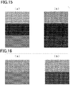
- Fig. 15(a) is an observation image of signal detection 3.
- the upper part of the image is a bright field image
- the middle part is a Redmond Red fluorescence image
- the lower part is an FITC fluorescence image.
- fluorescence of Redmond Red was not observed, and fluorescence of FITC was observed across the entire field.
- Fig. 15(b) is an observation image of signal detection 4.
- the upper part of the image is a bright field image
- the middle part is a Redmond Red fluorescence image
- the lower part is an FITC fluorescence image.
- Fig. 16(a) is an observation image of signal detection 1 according to Comparative Example 1.
- Fig. 17(a) is an observation image of signal detection 1 according to Comparative Example 2.
- the upper part of the image is a bright field image, and the lower part is a fluorescence image. As a result, fluorescence was observed across the entire field.
- Fig. 16(b) is an observation image of signal detection 2 according to Comparative Example 1.
- Fig. 17(b) is an observation image of signal detection 2 according to Comparative Example 2.
- the upper part of the image is a bright field image, and the lower part is a fluorescence image.
- fluorescence signals corresponding to the positions of the wells 142 were observed. That is, it was found that the first liquid was accommodated in each of the plurality of wells 142.
- Fig. 18(a) is an observation image of signal detection 3 according to Comparative Example 1.
- Fig. 19(a) is an observation image of signal detection 3 according to Comparative Example 2.
- the upper part of the image is a bright field image
- the middle part is a Redmond Red fluorescence image
- the lower part is an FITC fluorescence image.
- Redmond Red fluorescence signals corresponding to the positions of the wells 142 were observed. That is, it was found that the first liquid was accommodated in each of the plurality of wells 142. Further, FITC fluorescence signals were observed across the entire field.
- Fig. 18(b) is an observation image of signal detection 4 according to Comparative Example 1.
- Fig. 19(b) is an observation image of signal detection 4 according to Comparative Example 2.
- the upper part of the image is a bright field image, the middle part is a Redmond Red fluorescence image, and the lower part is an FITC fluorescence image.
- Redmond Red fluorescence signals corresponding to the positions of the wells 142 were observed. That is, it was found that the first liquid was accommodated in each of the plurality of wells 142. No fluorescence signal of FITC was observed.
- liquid in the wells 141 can be replaced with the second liquid when the first liquid contains a surfactant, even when the first liquid accommodated in the respective wells is sealed with the sealing solution. It was found that liquid in the wells 141 can be replaced with the second liquid regardless of whether the second liquid contains a surfactant or not. Further, it was found that, liquid in the wells 141 cannot be replaced with the second liquid when the first liquid does not contain a surfactant, even when the second liquid contains a surfactant.
- an image focusing on the wells 141 was taken via a surface on a side of the substrate 110 of the fluidic device 100 opposite to that on which the well array 140 was formed.
- the surface on a side of the substrate 110 opposite to that on which the well array 140 was formed was irradiated with excitation light.
- a fluorescence image was captured using the filter 1 at an exposure time of 1/4 second, and another fluorescence image was captured using the filter 2 at an exposure time of 1.5 seconds. Further, a bright field image of the same field was also captured.
- an image focusing on the wells 141 was taken via a surface on a side of the substrate 110 of the fluidic device 100 opposite to that on which the well array 140 was formed.
- the surface on a side of the substrate 110 opposite to that on which the well array 140 was formed was irradiated with excitation light.
- a fluorescence image was captured using the filter 1 at an exposure time of 5 seconds, and another fluorescence image was captured using the filter 2 at an exposure time of 1.5 seconds. Further, a bright field image of the same field was also captured.
- Fig. 20(a) is an observation image of signal detection 1.
- Fig. 20(b) is an observation image of signal detection 2.
- the upper part of the image is a bright field image, and the lower part is a fluorescence image.
- Fig. 21(a) is an observation image of signal detection 3.
- Fig. 21(b) is an observation image of signal detection 4.
- the upper part of the image is a bright field image, the middle part is a Redmond Red fluorescence image, and the lower part is an FITC fluorescence image.
- Fig. 22(a) is an observation image of signal detection 5.
- Fig. 22(b) is an observation image of signal detection 4.
- the upper part of the image is a bright field image, the middle part is a Redmond Red fluorescence image, and the lower part is an FITC fluorescence image.
- Fig. 23(a) is an observation image of signal detection 1.
- Fig. 23(b) is an observation image of signal detection 2.
- the upper part of the image is a bright field image, and the lower part is a fluorescence image.
- Fig. 24(a) is an observation image of signal detection 3.
- Fig. 24(b) is an observation image of signal detection 4.
- the upper part of the image is a bright field image, the middle part is a Redmond Red fluorescence image, and the lower part is an FITC fluorescence image.
- Fig. 25(a) is an observation image of signal detection 5.
- Fig. 25(b) is an observation image of signal detection 4.
- the upper part of the image is a bright field image, the middle part is a Redmond Red fluorescence image, and the lower part is an FITC fluorescence image.
- a final replacement liquid can be accommodated in the wells 141 when liquid containing a surfactant (in the present example, first liquid) is introduced into the wells 141 before the final replacement liquid is accommodated, even when liquid (in the present example, second liquid), which is introduced into the wells immediately before the final replacement liquid (in the present example, third liquid) is accommodated, does not contain a surfactant.
- Fig. 26(a) is an observation image of signal detection 1.
- Fig. 26(b) is an observation image of signal detection 2.
- the upper part of the image is a bright field image, and the lower part is a fluorescence image.
- Fig. 27(a) is an observation image of signal detection 3.
- Fig. 27(b) is an observation image of signal detection 4.
- the upper part of the image is a bright field image, the middle part is a Redmond Red fluorescence image, and the lower part is an FITC fluorescence image.
- the same results as in Comparative Example 1 were obtained.
- the image of Fig. 27(b) there are black voids, which correspond to some positions of the wells 142 in the Redmond Red fluorescence image. Since these positions of the black voids coincide with positions in the FITC fluorescence image where fluorescence signals are observed, it is found that replacement with the second liquid has occurred only in some of the wells 142. As described above, it is found that liquid in the wells 142 cannot be reliably replaced with the second liquid when the first liquid does not contain a surfactant.
- Fig. 28(a) is an observation image of signal detection 5.
- Fig. 28(b) is an observation image of signal detection 4.
- the upper part of the image is a bright field image, the middle part is a Redmond Red fluorescence image, and the lower part is an FITC fluorescence image.
- Example 2 An experiment was performed under the same conditions as in Example 1 except that the material of the cover member 120 of the fluidic device was modified to polypropylene (manufactured by AS ONE Corporation, product number: PPN-051001).
- Example 7 An experiment was performed under the same conditions as in Example 7 except that the first liquid and the second liquid did not contain a surfactant.
- Fig. 29(a) is an observation image of signal detection 1 according to Example 5.
- Fig. 29(b) is an observation image of signal detection 2 according to Example 5.
- Fig. 31(a) is an observation image of signal detection 1 according to Example 6.
- Fig. 31(b) is an observation image of signal detection 2 according to Example 6.
- Fig. 33(a) is an observation image of signal detection 1 according to Example 7.
- Fig. 33(b) is an observation image of signal detection 2 according to Example 7.
- the upper part of the image is a bright field image, and the lower part is a fluorescence image.
- Fig. 30(a) is an observation image of signal detection 3 according to Example 5.
- Fig. 30(b) is an observation image of signal detection 4 according to Example 5.
- Fig. 32(a) is an observation image of signal detection 3 according to Example 6.
- Fig. 32(b) is an observation image of signal detection 4 according to Example 6.
- Fig. 34(a) is an observation image of signal detection 3 according to Example 7.
- Fig. 34(b) is an observation image of signal detection 4 according to Example 7.
- the upper part of the image is a bright field image, the middle part is a Redmond Red fluorescence image, and the lower part is an FITC fluorescence image.
- Example 1 As seen from the results of Figs. 29 to 34 , the same results as in Example 1 were obtained in Examples 5 to 7. That is, it is found that the first liquid in the wells 142 that are individually sealed with the sealing solution can be replaced with the second liquid when the first liquid contains a surfactant, even when the cover member 120 of the fluidic device is made of glass, polypropylene, or silicone.
- Fig. 35(a) is an observation image of signal detection 1 according to Comparative Example 4.
- Fig. 35(b) is an observation image of signal detection 2 according to Comparative Example 4.
- Fig. 37(a) is an observation image of signal detection 1 according to Comparative Example 5.
- Fig. 37(b) is an observation image of signal detection 2 according to Comparative Example 5.
- Fig. 39(a) is an observation image of signal detection 1 according to Comparative Example 6.
- Fig. 39(b) is an observation image of signal detection 2 according to Comparative Example 6.
- the upper part of the image is a bright field image, and the lower part is a fluorescence image.
- Fig. 36(a) is an observation image of signal detection 3 according to Comparative Example 4.
- Fig. 36(b) is an observation image of signal detection 4 according to Comparative Example 4.
- Fig. 38(a) is an observation image of signal detection 3 according to Comparative Example 5.
- Fig. 38(b) is an observation image of signal detection 4 according to Comparative Example 5.
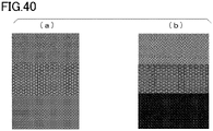
- Fig. 40(a) is an observation image of signal detection 3 according to Comparative Example 6.
- Fig. 40(b) is an observation image of signal detection 4 according to Comparative Example 6.
- the upper part of the image is a bright field image, the middle part is a Redmond Red fluorescence image, and the lower part is an FITC fluorescence image.
Landscapes
- Chemical & Material Sciences (AREA)
- Health & Medical Sciences (AREA)
- Analytical Chemistry (AREA)
- General Health & Medical Sciences (AREA)
- Dispersion Chemistry (AREA)
- Hematology (AREA)
- Clinical Laboratory Science (AREA)
- Chemical Kinetics & Catalysis (AREA)
- Physics & Mathematics (AREA)
- Life Sciences & Earth Sciences (AREA)
- Biochemistry (AREA)
- General Physics & Mathematics (AREA)
- Immunology (AREA)
- Pathology (AREA)
- Automatic Analysis And Handling Materials Therefor (AREA)
- Apparatus Associated With Microorganisms And Enzymes (AREA)
Abstract
Description
- The present invention relates to a method of introducing liquid into wells.
- The present application is based on and claims the benefit of priority from
Japanese Patent Application No. 2019-101305 filed May 30, 2019 - Early detection of disease and prediction of the effects of medication may be performed by quantitatively detecting a target molecule in a biological sample. Conventionally, protein quantification has been performed by enzyme-linked immunosorbent assay (ELISA) or the like, and nucleic acid quantification has been performed by the real-time PCR method or the like.
- In recent years, there is an increasing need for detecting a target molecule more accurately for the purpose of, for example, detecting disease earlier. For example, PTL 1, PTL 2, and NPL 1 disclose techniques for performing an enzyme reaction in a large number of micro compartments as techniques for accurately detecting a target molecule. These techniques are called digital quantification.
- In digital quantification, a sample solution is divided into a large number of micro compartments. Then, a signal from each micro compartment is binarized, and the number of target molecules is measured by determining only whether the target molecule is present or not. The digital quantification can significantly improve the detection sensitivity and the quantitativeness compared with conventional methods such as ELISA, real-time PCR method and the like.
- The digital quantification technology is widely used not only for the above diagnostic application, but also for an application in which a large number of target molecules are separated from each other and analyzed. For example, in NPL 2 and the like, the digital quantification technology is used for functional analysis of transmembrane proteins.
-
- PTL 1:
JP 5551798 B - PTL 2:
JP 2014-503831 T -
- NPL 1: Kim S. H., et al., Large-scale femtoliter droplet array for digital counting of single biomolecules, Lab on a Chip, 12 (23), 4986-4991, 2012.
- NPL 2: Rikiya Watanabe, et al., High-throughput formation of lipid bilayer membrane arrays with an asymmetric lipid composition, Scientific Reports volume 4, Article number: 7076, 2014.
- In digital quantification technology, a reaction reagent in which target molecules are mixed are divided into a large number of micro compartments using a sealing solution or a lipid bilayer. Then, a reaction is individually performed in the respective micro compartments to detect a target molecule. For this reason, the analysis results that can be obtained are usually limited to those according to the reaction reagent contained in the micro compartments. An object of the present invention is to provide a technique for replacing a liquid in the individually sealed micro compartments.
- The present invention includes the following aspects.
- [1] A method of introducing a second liquid into wells in a fluidic device which includes a substrate and a plurality of the wells, the wells being open to a first surface of the substrate and accommodating a first liquid containing a surfactant, and openings of the wells being sealed with a first sealing solution supplied onto the first surface, the method including: introducing the second liquid onto the first surface, whereby the first sealing solution is replaced with the second liquid.
- [2] The method according to the above [1], further including: introducing a second sealing solution into the fluidic device after the step of introducing the second liquid, whereby the openings of the plurality of wells are sealed with the second sealing solution supplied onto the first surface with the second liquid or a mixture of the first liquid and the second liquid being accommodated in the wells.
- [3] The method according to the above [1] or [2], further including before the step of introducing the second liquid: introducing the first liquid into the fluidic device; and introducing the first sealing solution into the fluidic device to seal the openings of the plurality of wells with the first sealing solution supplied onto the first surface with the first liquid being accommodated in the wells.
- [4] The method according to any one of the above [1] to [3], wherein the first liquid and the second liquid are miscible with each other.
- [5] The method according to any one of the above [1] to [4], wherein the fluidic device further includes a cover member disposed to face the first surface, and a space between the cover member and the first surface forms a flow path.
- [6] The method according to the above [5], wherein the second liquid is introduced into the fluidic device through the flow path.
- [7] The method according to any one of the above [1] to [6], wherein the first liquid and the second liquid contain a reaction reagent.
- [8] The method according to any one of the above [1] to [7], wherein at least part of components contained in the first liquid remains in the wells after the second liquid is introduced into the wells.
- [9] The method according to the above [8], wherein at least part of components contained in the first liquid is held by a carrier and remains in the wells.
- [10] The method according to any one of the above [1] to [9], wherein an affinity between the first surface and the first sealing solution is substantially the same or lower than affinity between the first surface and the second liquid.
- [11] The method according to the above [10], wherein the first surface is made of a cycloolefin polymer, the first liquid and the second liquid contain water as a main component, and the first sealing solution is a fluorine-based oil.
- According to the present invention, a technique for replacing liquid in the individually sealed micro compartments can be provided.
-
-
Fig. 1 is a schematic cross-sectional view illustrating an example of a fluidic device. -
Fig. 2 is a schematic cross-sectional view illustrating an example of a fluidic device. -
Fig. 3 is a schematic cross-sectional view illustrating an example of a fluidic device. -
Fig. 4 is a schematic cross-sectional view illustrating an example of a fluidic device. -
Fig. 5 is a schematic cross-sectional view illustrating an example of a fluidic device. -
Fig. 6 is a schematic cross-sectional view illustrating an example of a fluidic device. -
Fig. 7 is a schematic cross-sectional view illustrating an example of a fluidic device. -
Fig. 8 is a schematic cross-sectional view illustrating an example of a fluidic device. -
Fig. 9 is a schematic cross-sectional view illustrating an example of a fluidic device. -
Fig. 10 is a schematic cross-sectional view illustrating an example of a fluidic device. -
Fig. 11 is a schematic cross-sectional view illustrating an example of a fluidic device. -
Fig. 12 is a microscopic image showing results obtained using Example 1. -
Fig. 13 is a microscopic image showing results obtained using Example 1. -
Fig. 14 is a microscopic image showing results obtained using Example 2. -
Fig. 15 is a microscopic image showing results obtained using Example 2. -
Fig. 16 is a microscopic image showing results obtained using Comparative Example 1. -
Fig. 17 is a microscopic image showing results obtained using Comparative Example 2. -
Fig. 18 is a microscopic image showing results obtained using Comparative Example 1. -
Fig. 19 is a microscopic image showing results obtained using Comparative Example 2. -
Fig. 20 is a microscopic image showing results obtained using Example 3. -
Fig. 21 is a microscopic image showing results obtained using Example 3. -
Fig. 22 is a microscopic image showing results obtained using Example 3. -
Fig. 23 is a microscopic image showing results obtained using Example 4. -
Fig. 24 is a microscopic image showing results obtained using Example 4. -
Fig. 25 is a microscopic image showing results obtained using Example 4. -
Fig. 26 is a microscopic image showing results obtained using Comparative Example 3. -
Fig. 27 is a microscopic image showing results obtained using Comparative Example 3. -
Fig. 28 is a microscopic image showing results obtained using Comparative Example 3. -
Fig. 29 is a microscopic image showing results obtained using Example 5. -
Fig. 30 is a microscopic image showing results obtained using Example 5. -
Fig. 31 is a microscopic image showing results obtained using Example 6. -
Fig. 32 is a microscopic image showing results obtained using Example 6. -
Fig. 33 is a microscopic image showing results obtained using Example 7. -
Fig. 34 is a microscopic image showing results obtained using Example 7. -
Fig. 35 is a microscopic image showing results obtained using Comparative Example 4. -
Fig. 36 is a microscopic image showing results obtained using Comparative Example 4. -
Fig. 37 is a microscopic image showing results obtained using Comparative Example 5. -
Fig. 38 is a microscopic image showing results obtained using Comparative Example 5. -
Fig. 39 is a microscopic image showing results obtained using Comparative Example 6. -
Fig. 40 is a microscopic image showing results obtained using Comparative Example 6. - With reference to the drawings as appropriate, embodiments of the present invention will be described in detail. Throughout the drawings, the same or corresponding parts are denoted by the same or corresponding reference numerals, and duplicated description is omitted. Further, some of the dimensions in the drawings are exaggerated for convenience of illustration, and are not necessarily to scale.
- An embodiment of the present invention provides a method of introducing a second liquid into wells in a fluidic device which includes a substrate and a plurality of the wells, the wells being open to a first surface of the substrate and accommodating a first liquid containing a surfactant, and openings of the wells being sealed with a first sealing solution supplied onto the first surface, the method including: introducing the second liquid onto the first surface, whereby the first sealing solution is replaced with the second liquid.
- According to the method of the present embodiment, liquid in the individually sealed micro compartments can be replaced. Accordingly, in digital quantification technology, for example, after an analysis result is obtained using a reaction reagent contained in a first liquid introduced into the micro compartments, the liquid in the micro compartments is replaced with a second liquid so that another analysis can be performed using a reaction reagent contained in the second liquid.
- First, a fluidic device that can be used in the method of the present embodiment will be described.
Fig. 1 is a schematic cross-sectional view illustrating an example of a fluidic device. As shown inFig. 1 , afluidic device 100 includes asubstrate 110, and acover member 120 disposed to face afirst surface 111 of thesubstrate 110. Thecover member 120 has aprojection 121. The distal end of theprojection 121 is in contact with thesubstrate 110. In thefluidic device 100, a plurality ofwells 141, forming awell array 140, are integrally formed on thefirst surface 111 of thesubstrate 110. Thefirst surface 111 faces thecover member 120. Thecover member 120 may be welded or bonded to thesubstrate 110. - The
wells 141 are open to a surface of thesubstrate 110. Although the shape, size, and arrangement of thewells 141 are not specifically limited, it is preferred that one target molecule is introduced into each well 141. Thewells 141 are preferably microwells having a small volume. For example, each well 141 may have a volume of approximately 10 fL to 100 pL. In thefluidic device 100, the plurality ofwells 141 having the same shape and the same size constitute thewell array 140. The expression "the same shape and the same size" refers to the shape and the volume being the same to the extent required for digital quantification, and a variation approximately within a manufacturing error may be accepted. - The well 141 may have a diameter of, for example, approximately 1 to 30 µm. The well 141 may have a depth of, for example, approximately 1 to 30 µm. Further, the arrangement of the
wells 141 is not specifically limited. For example, thewells 141 may be arranged in a triangular lattice or a square lattice shape, or randomly arranged. - In the
fluidic device 100, since theprojection 121 is provided, a space is formed between thefirst surface 111 and thecover member 120. The space constitutes aflow path 130. Theflow path 130 functions as a path for supplying a first liquid, a first sealing solution, a second liquid, and a second sealing solution, which will be described later. That is, the first liquid, the first sealing solution, the second liquid, and the second sealing solution are introduced into thefluidic device 100 through theflow path 130. - Although the shape, structure, volume, and the like of the
flow path 130 are not specifically limited, the height of the flow path 130 (that is, a distance between thefirst surface 111 of thesubstrate 110 and a surface of thecover member 120 facing the substrate 110) may be, for example, 100 µm or less. - The
projection 121 may be molded integrally with thecover member 120. For example, thecover member 120 can be formed as a plate shape having theprojection 121 by molding a thermoplastic resin fluid using a mold. In addition, aninlet port 122 and adischarge port 123 for a reagent may also be formed on thecover member 120. - When the
cover member 120 includes theprojection 121, thecover member 120 and thesubstrate 110 are stacked with theprojection 121 being in contact with thesurface 111 of thesubstrate 110 to which thewells 141 are open. A space thus formed between thecover member 120 and thesubstrate 110 is provided as theflow path 130. Thecover member 120 and thesubstrate 110 may be welded to each other by laser welding or the like. - A fluidic device used for the method of the present embodiment is not limited to the
above fluidic device 100.Fig. 7 is a schematic cross-sectional view illustrating an example of a fluidic device. As shown inFig. 7 , afluidic device 200 includes thesubstrate 110 and awall member 210. In thefluidic device 200, thewell array 140 is molded integrally with thesubstrate 110 on thefirst surface 111 of thesubstrate 110. Thewell array 140 includes a plurality ofwells 141. - The
fluidic device 200 differs from theabove fluidic device 100 mainly in that it does not include thecover member 120. Accordingly, thefluidic device 200 does not include a flow path. - In the
above fluidic device 100, thecover member 120 and theprojection 121 are integrally molded. However, thecover member 120 and theprojection 121 may also be molded as separate members. - Further, in the
above fluidic device 100 and thefluidic device 200, thewell array 140 is molded integrally with thesubstrate 110 on thefirst surface 111 of thesubstrate 110. However, the well array may not necessarily be molded integrally with thesubstrate 110. For example, awell array 140 molded separately from the fluidic device may be disposed on thesubstrate 110 of the fluidic device. Alternatively, a resin layer may be laminated on a surface of thesubstrate 110 to form a well array on the resin layer by etching or the like. - The
substrate 110 is formed using a resin, for example. Although the type of the resin is not specifically limited, it is preferred that the resin is resistant to the first liquid, the second liquid, and the sealing solutions. Further, when a signal to be detected is fluorescence, it is preferred that the resin has low autofluorescence. Examples of the resin may include, but are not limited to, a cycloolefin polymer, a cycloolefin copolymer, silicone, polypropylene, polycarbonate, polystyrene, polyethylene, polyvinyl acetate, a fluororesin, an amorphous fluororesin, and the like. - A plurality of
wells 141 may be formed on thefirst surface 111 located on one side of thesubstrate 110 in the thickness direction. The wells may be formed using a resin by injection molding, thermal imprinting, optical imprinting, or the like. - Alternatively, for example, a fluororesin may be laminated on the
substrate 110 to form a well array on the fluororesin by etching or the like. As the fluororesin, for example, CYTOP (registered trademark) (Asahi Glass Co., Ltd.) or the like may be used. - When the fluidic device includes the
cover member 120, the material of thecover member 120 is preferably a resin having low autofluorescence, and may be, for example, a thermoplastic resin such as a cycloolefin polymer or a cycloolefin copolymer. - Further, the
cover member 120 may also be formed of a material that does not transmit light of a wavelength near the wavelength detected in fluorescence observation of a signal, or a material that only partially transmits light. For example, thecover member 120 may be formed of a thermoplastic resin to which carbon or metal particles are added. - As described above, a method of the present embodiment is a method of introducing a second liquid into wells in a fluidic device which includes a substrate and a plurality of the wells, the wells being open to a first surface of the substrate and accommodating a first liquid containing a surfactant, and openings of the wells being sealed with a first sealing solution supplied onto the first surface, the method including: introducing the second liquid onto the first surface, whereby the first sealing solution is replaced with the second liquid.
- With reference to
Figs. 1 to 6 as appropriate, a method of a first embodiment will be described by using an example in which thefluidic device 100 is used. - First, as shown in
Fig. 1 , a first liquid L110 is introduced through theinlet port 122 of thefluidic device 100 into theflow path 130. The first liquid L110 includes, for example, biological samples or environmental samples. Examples of the biological samples may include, but are not limited to, serum, plasma, urine, cell culture solution, and the like. In addition, examples of the environmental samples may include river water, factory wastewater, and the like. - The biological samples and environmental samples may contain target molecules to be detected. Alternatively, the biological samples and environmental samples may not contain target molecules to be detected. Examples of the target molecules include DNA, RNA, proteins, viruses, cells, specific compounds, and the like. The RNA may be miRNA, mRNA, or the like. Further, the cells may be bacteria, yeast, animal cells, plant cells, insect cells, or the like.
- The first liquid L110 may contain a reaction reagent for detecting a target molecule. Examples of the reaction reagent include buffer substances, enzymes, substrates, antibodies, antibody fragments, and the like. The enzyme is selected according to the content of biochemical reaction. For example, when the target molecule is a nucleic acid, the enzyme is selected to perform a biochemical reaction such as an enzyme reaction with a template nucleic acid associated with the target molecule. The biochemical reaction to the template nucleic acid is, for example, a reaction in which signal amplification occurs in the presence of a template nucleic acid. The reaction reagent is selected according to the detection reaction to be employed. Specific examples of the detection reaction include an invasive cleavage assay (ICA) method, loop-mediated isothermal amplification (LAMP) method (registered trademark), 5'→3' nuclease method (TaqMan (registered trademark)), fluorescent probe method, and the like.
- The first liquid L110 contains a surfactant. Examples of the surfactant include Triton-X100 (also known as polyethylene glycol mono-4-octylphenyl ether (n=approx. 10)), sodium dodecyl sulfate, Nonidet P-40 (also known as octylphenoxy poly(ethyleneoxy)ethanol), Tween20 (also known as polyoxyethylene sorbitan monolaurate), and the like.
- The concentration of the surfactant is preferably 0.001 v/v% or more and 1.0 v/v% or less relative to the total volume of the first liquid L110, more preferably 0.005 v/v% or more and 0.5 v/v% or less, and still more preferably 0.01 v/v% or more and 0.1 v/v% or less. When the concentration of the surfactant is 0.001 v/v% or more relative to the total volume of the first liquid L110, replacement with the second liquid L410 can be easily performed. When the concentration of the surfactant is 1.0 v/v% or less relative to the total volume of the first liquid L110, the influence on the reaction in the subsequent detection of target molecule can be minimized.
- The first liquid L110 supplied into the
flow path 130 is accommodated in thewells 141. Accordingly, the reaction reagent, the surfactant, and target molecules, if present, are introduced into thewells 141. - Although the number of target molecules introduced into each well 141 is not specifically limited, it is preferred that 1 or less, that is, 0 or 1 target molecule is introduced into each well 141. Accordingly, the target molecule can be detected in units of one piece, that is, digital quantification can be performed. The target molecule is not necessarily introduced into every well 141 of the
well array 140. - A means for introducing target molecules into the
wells 141 is not specifically limited, and an appropriate means for the selected target molecule can be used. For example, target molecules may precipitate by their own weight in the fluidic device (specifically, in the flow path), and be distributed into thewells 141. Alternatively, a carrier (that is, capture substance) for capturing target molecules may be used. The target molecules that are unlikely to precipitate by their own weight can be bound to the capture substances when they are supplied. Further, the capture substances can be immobilized to thewells 141 in advance so as to capture target molecules that are supplied. Accordingly, the target molecules can be introduced into the wells at improved efficiency. - The step of binding the capture substances to the target molecules can be performed at any time. For example, the step may be performed by bringing the target molecules and the capture substances into contact with each other in a sample tube before the target molecules are introduced into the
wells 141. Alternatively, the target molecules may be introduced into the wells after the capture substances are introduced into thewells 141 so that the capture substances and the target molecules are in contact with other in the wells. - The capture substance is a substance capable of capturing target molecules. The capture substance may be, for example, a conjugate of a solid phase and a specific binding substance for the target molecule.
- The solid phase may be particles, films, substrates, or the like. Further, the specific binding substance for the target molecule may be one or more. For example, three, four, or five or more specific binding substances may be used.
- The particles are not specifically limited, and may be polymer particles, magnetic particles, glass particles, or the like. Preferably, the particles are subjected to a surface treatment in order to avoid nonspecific adsorption. Further, in order to immobilize the specific binding substance, particles having a functional group such as a carboxyl group on the surface are preferred. More specifically, a product "Magnosphere LC300" manufactured by JSR Corporation or the like can be used as the particles.
- Alternatively, for example, when a virus is used as the target molecule, a cell to which the virus can be attached (that is, a cell having a virus receptor) can be used as the capture substance.
- Examples of the specific binding substance in the capture substance include antibodies, antibody fragments, aptamers, and the like. Examples of the antibody fragment include Fab, F(ab')2, Fab', single chain antibodies (scFv), disulfide stabilized antibodies (dsFv), dimeric V region fragments (Diabody), peptides including CDR, and the like. The antibody may be a monoclonal antibody or a polyclonal antibody. Alternatively, the antibody may be a commercially available antibody.
- When the target molecule contains a sugar chain, the specific binding substance may be a lectin. Further, when the target molecule contains a lipid membrane, the specific binding substance may be a substance that binds to the lipid membrane. Examples of the substance that binds to lipid membrane include hydrocarbons such as hexanediol and membrane proteins such as transmembrane proteins. The membrane proteins may be, for example, α-hemolysin.
- The method of immobilizing the specific binding substance to the solid phase is not limited, and it is possible to use a method using physical adsorption, a method using chemical bonding, a method using avidin-biotin binding, a method of using a bond between protein G or protein A to an antibody, or the like. As the method by physical adsorption, there is a method of immobilizing a specific binding substance to the particle surface by hydrophobic interaction or electrostatic interaction. As the method by chemical bonding, there is a method using a crosslinking agent. For example, in the case where the surface of the particle has a hydroxyl group, the carboxyl group of the specific binding substance is allowed to react with a crosslinking agent to obtain an active ester, and then the hydroxyl group and the ester group are allowed to react, whereby the specific binding substance can be immobilized to the particle surface. It is also preferable to provide a spacer between the specific binding substance and the particle surface so as not to inhibit the recognition ability of the specific binding substance to recognize the target molecule.
- When a capture substance is used to introduce target molecules into the
wells 141, it is preferred that conjugates of the capture substances and the target molecules are formed under the condition that each capture substance captures 0 or 1 target molecule. Furthermore, each well 141 is preferably configured to accommodate 0 or 1 capture substance. Thus, digital quantification can be performed. - Then, as shown in
Figs. 2 and3 , a first sealing solution L120 is introduced through theinlet port 122 into theflow path 130. - Due to the first sealing solution, the liquid which has been introduced into the plurality of
wells 141 can be individually sealed, forming liquid droplets (microdroplets). Accordingly, the liquid in each well can be prevented from being mixed with one another. The first sealing solution is preferably an oily solution, and more preferably an oil. Examples of the oil include fluorine-based oil, silicone-based oil, hydrocarbon-based oil, and a mixture thereof. More specifically, oil manufactured by Sigma under the product name "FC-40" or the like can be used. FC-40 (CAS Number: 86508-42-1) is a fluorinated aliphatic compound having a specific weight of 1.85 g/mL at 25°C. - The first sealing solution L120 supplied to the
flow path 130 flushes out and replaces the first liquid L110 which has been introduced into theflow path 130 and is not accommodated in thewells 141. As a result, the plurality ofwells 141 are individually sealed by the first sealing solution L120, whereby thewells 141 are provided as independent reaction spaces (micro compartments 142). - As the
flow path 130 is filled with the first sealing solution L120, excess first sealing solution L120 is discharged through thedischarge port 123.Fig. 3 illustrates that all thewells 141 of thewell array 140 are sealed with the first sealing solution L120 and form sealed wells (micro compartments) 142. - Alternatively, the first liquid L110 may contain lipids dissolved therein. After the first sealing solution L120 is supplied into the
flow path 130, a liquid containing lipids may be again supplied into theflow path 130 to form a lipid bilayer at the openings of thewells 141. Thus, the plurality ofwells 141 are individually sealed with the lipid bilayer, whereby sealedwells 142 are formed. Examples of the lipid forming the lipid bilayer include, but are not limited to, 1,2-dioleoyl-sn-glycero-3-phosphoethanolamine (DOPE), 1,2-dioleoyl-sn-glycero-3-phosphoglycerol (DOPG), and a mixture thereof. - Target molecules can be detected by using a reaction of a reaction reagent contained in the first liquid L110. For example, a signal amplification reaction may be performed in the sealed
wells 142. In other words, a reaction step is performed in which a signal is amplified to a level at which the signal is observable so that a signal derived from a reaction reagent can be detected in thewells 142. Examples of the signal include fluorescence, color development, potential change, pH change, and the like. - The signal amplification reaction is, for example, an enzymatic reaction. As an example, the signal amplification reaction is an isothermal reaction in which, in a state in which the first liquid L110 containing an enzyme for signal amplification is accommodated in the
wells 142, thefluidic device 100 is maintained at a constant temperature condition for a predetermined period of time so that a desired enzyme activity is obtained. As a specific example, an ICA reaction can be used as the signal amplification reaction. In this case, thewells 142 accommodate the ICA reaction reagent and a nucleic acid as a target molecule. When the target molecule is accommodated in thewells 142 as a result of the enzymatic reaction, a fluorescent substance is released from a quencher, whereby a specified fluorescence signal is emitted corresponding to the excitation light. InFig. 3 ,reference symbol 142R indicates a well in which a target molecule is accommodated and a signal is emitted. - Then, as shown in
Fig. 4 , a second liquid L140 is introduced through theinlet port 122 into theflow path 130. As a result, the second liquid L410 flushes out the first sealing solution L120, and is introduced into thewells 141. Although it is preferred that the first sealing solution L120 is completely replaced with the second liquid L410 and removed, the first sealing solution L120 may be partially left as long as the second liquid L410 is introduced into thewells 141. - Conventionally, it has been thought that liquid in the
wells 142 sealed with a sealing solution cannot be replaced. However, the inventors have found that, according to the method of the present embodiment described later in the examples, the second liquid L410 can be introduced into thewells 142 which are sealed with the first sealing solution L120. - The second liquid L410 may contain a surfactant, or may not contain a surfactant. When the second liquid L410 contains a surfactant, the type and concentration of the surfactant may be the same as the surfactant of the first liquid L110.
- Similarly to the first liquid L110, the second liquid L410 may also contain a reaction reagent for detecting target molecules. Examples of the reaction reagent may be the same as those that can be contained in the first liquid L110 described above, but the reagent is preferably different from that of the first liquid L110. Accordingly, a reaction different from that by the reaction reagent contained in the first liquid L110 can be performed.
- The second liquid L410 supplied to the
flow path 130 flushes out and replaces the first sealing solution L120 which has been introduced into theflow path 130. This releases the sealing of the individually sealedwells 142, and provides unsealedwells 141. Further, the second liquid L410 is introduced into thewells 141 in which the first liquid L110 is accommodated. - In the method of the first embodiment, it is preferred that the affinity between the
first surface 111 and the sealing solution L120 is substantially the same as that between thefirst surface 111 and the second liquid L410, or lower than that between thefirst surface 111 and the second liquid L410. Accordingly, as the second liquid L410 is introduced, the second liquid L410 can easily flush out the first sealing solution L120 to thereby release the sealing of thewells 142. - Examples of the case where the affinity between the
first surface 111 and the first sealing solution L120 is substantially the same or lower than the affinity between thefirst surface 111 and the second liquid L410 include a combination in which thefirst surface 111 is made of a cycloolefin polymer, the first liquid L110 and the second liquid L410 contain water as a main component, and the first sealing solution L120 is a fluorine-based oil. - In the present specification, the liquid containing water as a main component means that the water content in the liquid is 50 mass% or more, for example, 60 mass% or more, 70 mass% or more, 80 mass% or more, 90 mass% or more, 95 mass% or more, or 98 mass% or more. Further, the fluorine-based oil may be, for example, oil manufactured by Sigma under the product name "FC-40" or the like.
- Since the first liquid L110 contains a surfactant, the second liquid L410 is introduced into the unsealed
wells 141. As a result, liquid in thewells 141 can be replaced with the second liquid L410. That is, after the first liquid L110 containing a surfactant is introduced into thewells 141 and the first liquid L110 is then sealed with the first sealing solution L120, the second liquid L410 is introduced so that liquid in thewells 141 can be replaced with the second liquid L410. - After the second liquid L410 is introduced into the
wells 141, at least part of the components contained in the first liquid L110 may remain in thewells 141. For example, while a target molecule contained in the first liquid L110 is bound to the capture substance, the capture substance may remain in thewells 141. That is, at least part of the components contained in the first liquid L110 held by the capture substance (carrier) may remain in thewells 141. In this case, the second liquid L410 is present in thewells 141 together with the capture substance and the target molecule. - Alternatively, for example, while a target molecule contained in the first liquid L110 is bound to the capture substance, and an antibody against the target molecule contained in the first liquid L110 is further bound to the target molecule, the capture substance may remain in the
wells 141. In this case, the second liquid L410 is present in thewells 141 together with the capture substance, the target molecule, and the antibody bound to the target molecule. - The first liquid L110 and the second liquid L410 are preferably miscible with each other. When the first liquid L110 and the second liquid L410 are miscible with each other, liquid in the
wells 141 is efficiently replaced. The term miscible herein refers to that, when the first liquid L110 and the second liquid L410 are mixed with each other, a homogeneous solution or dispersion is formed without being separated into layers. - When the
flow path 130 is filled with the second liquid L410, an excess second liquid L410 is discharged through thedischarge port 123. - After a step of introducing the second liquid L410, a step of introducing a second sealing solution L120 into the
fluidic device 100 may be further performed. The second sealing solution may be the same as the above first sealing solution, or different from the first sealing solution. Specifically, as shown inFig. 5 , the second sealing solution L120 may be again introduced through theinlet port 122 into theflow path 130. - As a result, the openings of the plurality of
wells 141 are sealed with the second sealing solution L120 which is supplied onto thefirst surface 111 with the second liquid L410 or a mixture of the first liquid L110 and the second liquid L410 being accommodated in thewells 141, whereby therespective wells 141 are provided as independent reaction spaces (micro compartments 142). - As the
flow path 130 is filled with the second sealing solution L120, excess second sealing solution L120 is discharged through thedischarge port 123.Fig. 6 illustrates that all thewells 141 of thewell array 140 are sealed with the second sealing solution L120 and form sealed wells (micro compartments) 142. - Alternatively, the second liquid L410 may contain lipids dissolved therein. After the second sealing solution L120 is supplied into the
flow path 130, a liquid containing lipids may be again supplied into theflow path 130 to form a lipid bilayer at the openings of thewells 141. Thus, the plurality ofwells 141 are individually sealed with the lipid bilayer, whereby sealedwells 142 are formed. Examples of the lipids forming the lipid bilayer include those described above. - Target molecules can be detected by using a reaction of a reaction reagent contained in the second liquid L410 in the same manner as described above. For example, a signal amplification reaction may be performed in the sealed
wells 142. InFig. 6 ,reference symbol 142R indicates a well in which a target molecule is accommodated and a signal is emitted as a result of reaction of the reaction reagent. - Next, with reference to
Figs. 7 to 11 , a method of a second embodiment will be described by using an example in which afluidic device 200 is used. The method of the second embodiment differs from that of the first embodiment in that the fluidic device does not include a cover member. Further, a first sealing solution and a second sealing solution in the method of the second embodiment differ from the first sealing solution and the second sealing solution in the method of the first embodiment in that they are required to satisfy the specific weight conditions described later. - First, as shown in
Fig. 7 , the first liquid L110 is introduced into thefluidic device 200. The first liquid L110 is the same as that described above. As shown inFig. 7 , the first liquid L110 is accommodated in thewells 141. Accordingly, the reaction reagent and target molecules, if present, are introduced into thewells 141. Although the number of target molecules introduced into each well 141 is not specifically limited, it is preferred that 1 or fewer, that is, 0 or 1 target molecule is introduced into each well 141. - Then, as shown in
Fig. 8 , the first sealing solution L120 is introduced into thefluidic device 200. The specific weight of the first sealing solution L120 is larger than the specific weight of the first liquid L110. Accordingly, the first sealing solution L120 precipitates under the first liquid L110, and is in contact with thefirst surface 111. Thus, a plurality of wells 241, in which the first liquid L110 is accommodated, are individually sealed by the sealing solution L120, forming independent reaction spaces (micro compartments 142). - Then, as shown in
Fig. 9 , a predetermined reaction may be performed in thewells 142 to observe a generated signal. InFig. 9 , thewells 142R are wells in which a target molecule is accommodated and a signal is detected, and thewells 142 are wells in which no target molecule is accommodated and no signal is detected. - Then, as shown in
Fig. 10 , the second liquid L410 is introduced into thefluidic device 200. The specific weight of the second liquid L410 is larger than the specific weight of the first sealing solution L120. Accordingly, the second liquid L410 precipitates under the first sealing solution L120. This releases the sealing of the individually sealedwells 142, and provides unsealedwells 141. Further, the second liquid L410 is introduced into thewells 141. In thewells 141, it is preferred that the first sealing solution L120 is completely replaced with the second liquid L410 and removed. However, the first sealing solution L120 may be partially left as long as the second liquid L410 is introduced into thewells 141. - The second liquid L410 may contain a reaction reagent for detecting a target molecule. Examples of the reaction reagent may be the same as those that can be contained in the first liquid L110 described above, but the reagent is preferably different from that of the first liquid L110. Accordingly, a reaction different from that by the reaction reagent contained in the first liquid L110 can be performed.
- In the second embodiment, as in the first embodiment, at least part of the components contained in the first liquid L110 may remain in the
wells 141 after the second liquid L410 is introduced into thewells 141. - After a step of introducing the second liquid L410, a step of introducing a second sealing solution L620 into the
fluidic device 200 may be further performed. Specifically, as shown inFig. 11 , the second sealing solution L620 is introduced into thefluidic device 200. The specific weight of the second sealing solution L620 is larger than the specific weight of the second liquid L410. Accordingly, the second sealing solution L620 precipitates under the second liquid L410, and is in contact with thefirst surface 111. Thus, a plurality of wells 241, in which the second liquid L410 or a mixture of the first liquid L110 and the second liquid L410 is accommodated, are individually sealed by the second sealing solution L620, forming independent reaction spaces (micro compartments 142). -
Fig. 11 illustrates that all thewells 141 of thewell array 140 are sealed with the second sealing solution L620 and form sealed wells (micro compartments) 142. - Target molecules can be detected by using a reaction of a reaction reagent contained in the second liquid L410 in the same manner as described above. For example, a signal amplification reaction may be performed in the sealed
wells 142. InFig. 11 ,reference symbol 142R indicates a well in which a target molecule is accommodated and a signal is emitted as a result of reaction of the reaction reagent. - In the method of the second embodiment, it is preferred that the specific weight of the first sealing solution L120 is larger than the specific weight of the first liquid L110, the specific weight of the second liquid L410 is larger than the specific weight of the first sealing solution L120, and the specific weight of the second sealing solution L620 is larger than the specific weight of the second liquid L410. Further, the main component of the first liquid L110 and the second liquid L410 is preferably water. In this case, for example, the specific weight can be adjusted by adding sucrose or the like to the second liquid L410. Further, as the first sealing solution L120 and the second sealing solution L620, materials satisfying the requirements such as specific weight can be appropriately selected from those described above.
- In the embodiment described above, the liquid in the micro compartments individually sealed is replaced once. However, according to an aspect of the present invention, the liquid in the individually sealed micro compartments can be replaced twice or more. That is, the liquid can be replaced a desired number of times by repeating an aspect of the present invention.
- Specifically, in the above example, the steps of introducing the first liquid L110, sealing by the first sealing solution L120, and introducing the second liquid L410 are sequentially performed. However, these steps are not necessarily sequentially performed. For example, a third liquid may be introduced into the
fluidic device 100 between the steps of sealing by the first sealing solution L120 and introducing the second liquid L410, and a third liquid may be sealed in thewells 142 by a third sealing solution. The third liquid may contain a surfactant, or may not contain a surfactant. Even when the third liquid does not contain a surfactant, the liquid containing no surfactant in thewells 141 can be replaced with the second liquid L410 by introducing the second liquid L410 into thefluidic device 100. - The reason for this seems to be that, since a surfactant is introduced into the
wells 141 due to introduction of the first liquid L110, the surfactant may remain in thewells 141 or may be attached to an inner wall of thewells 141 even when liquid in thewells 141 is replaced with liquid containing no surfactant. Accordingly, when the second liquid L410 is introduced, liquid in thewells 141 can be replaced with the second liquid L410 due to an effect of the surfactant remaining in thewells 141. - Further, a fourth liquid may be introduced between the steps of sealing by the third sealing solution and introducing the second liquid L410, and a fourth liquid may be sealed in the
wells 141 by a fourth sealing solution. The fourth liquid may contain a surfactant, or may not contain a surfactant. - According to an aspect of the present invention, when a plurality of target molecules are included in a sample, for example, when the sample is a cell or the like, the target molecules can be detected in a simplified manner. One example is described below.
- A first
liquid L 110 containing cells and a first reaction reagent is introduced into thewells 141. In this case, the cells are preferably introduced into thewells 141 using capture substances. The capture substances, configured such that cells bound to the capture substances remain in thewells 142 after the second liquid L410 is introduced, are used. For example, capture substances having a sufficiently large mass or capture substances immobilized in thewells 141 may be used. - Then, a first sealing solution is introduced to obtain
wells 142, and detection of first target molecules is performed using the first reaction reagent. Further, a second liquid L410 containing a second reaction reagent is introduced into thewells 141 to replace liquid in thewells 141 with the second liquid. Then, a second sealing solution is introduced into theflow path 130 to obtain sealedwells 142. Thewells 142 then contain cells bound to the capture substances, and the second liquid L410. Then, detection of second target molecules is performed using the second reaction reagent. - As described above, when a plurality of target substances are included in the sample, the plurality of target substances can be detected in a simplified manner without using a plurality of devices.
- The present invention will be described in more detail using the examples, but the present invention is not limited to the following examples.
- First, a fluidic device having a structure as shown in
Fig. 1 was produced. The fluidic device was produced by adhering asubstrate 110 and acover member 120 to each other with a double-sided tape. Thesubstrate 110, made of a cycloolefin polymer, was formed by injection molding and provided with awell array 140, and thecover member 120, made of a cycloolefin polymer, was colored by adding a carbon black. The double-sided tape functioned as aprojection 121, and a height of the flow path 130 (a distance between thefirst surface 111 of thesubstrate 110 and a surface of thecover member 120 facing the substrate 110) was 100 µm. Further, thecover member 120 was provided with aninlet port 122 and adischarge port 123. In addition, each well 141 constituting thewell array 140 had a diameter of 5 µm and a depth of 3 µm. A volume Vd of each well 141 was 93 fL. - Liquid containing water (AccuGENE Molecular Biology Grade Water (manufactured by LONZA)) as a solvent, 5 µg/ml Redmond Red as a fluorescent reagent, 10 mM Tris-HCl (manufactured by Nippon Gene, pH:8.5) as a buffer, 6.25 mM MgCl2 (manufactured by SIGMA-ALDRICH) as a salt, and 0.1 v/v% Tween 20 (manufactured by SIGMA-ALDRICH) as a surfactant was prepared as the first liquid and the third liquid.
- Liquid containing water (AccuGENE Molecular Biology Grade Water (manufactured by LONZA)) as a solvent, 1 µg/ml fluorescein isothiocyanate (hereinafter, FITC) as a fluorescent reagent, 10 mM Tris-HCl (manufactured by Nippon Gene, pH:8.5) as a buffer, 6.25 mM MgCl2 (manufactured by SIGMA-ALDRICH) as a salt, and 0.1 mass% Tween 20 (manufactured by SIGMA-ALDRICH) as a surfactant was prepared as the second liquid.
- Oil (Fluorinert FC-40, manufactured by SIGMA-ALDRICH) was used as the sealing solution.
- The devices used were as follows.
- Microscope: BZ-800 (manufactured by Keyence)
- Objective lens: CFI Plan Apochromat Lambda 10X (manufactured by Nikon)
- Filter 1: BZ-X filter TexasRed (manufactured by Keyence)
- Filter 2: BZ-X filter GFP (manufactured by Keyence)
- 20 µL of the first liquid was introduced through the
inlet port 122 of the fluidic device. - Then, using a fluorescence microscope, an image focusing on the
wells 141 was taken via a surface on a side of thesubstrate 110 of thefluidic device 100 opposite to that on which thewell array 140 was formed. In this process, the surface on a side of thesubstrate 110 opposite to that on which thewell array 140 was formed was irradiated with excitation light. A fluorescence image was captured using the filter 1 at an exposure time of 1/4 second. Further, a bright field image of the same field was also captured. -
Fig. 12(a) is an observation image of signal detection 1. The upper part of the image is a bright field image, and the lower part is a fluorescence image. As a result, fluorescence was observed across the entire field. - 100 µL of the sealing solution was introduced through the
inlet port 122 of the fluidic device. As a result, thewells 141 were individually sealed, and sealedwells 142 were formed. - Then, using a fluorescence microscope, an image focusing on the
wells 141 was taken via a surface on a side of thesubstrate 110 of thefluidic device 100 opposite to that on which thewell array 140 was formed. In this process, the surface on a side of thesubstrate 110 opposite to that on which thewell array 140 was formed was irradiated with excitation light. A fluorescence image was captured using the filter 1 at an exposure time of 5 seconds. Further, a bright field image of the same field was also captured. -
Fig. 12(b) is an observation image of signal detection 2. The upper part of the image is a bright field image, and the lower part is a fluorescence image. As a result, fluorescence signals corresponding to the positions of thewells 142 were observed. That is, it was found that the first liquid was accommodated in each of the plurality ofwells 142. - 20 µL of the second liquid was introduced through the
inlet port 122 of the fluidic device. - Then, using a fluorescence microscope, an image focusing on the
wells 141 was taken via a surface on a side of thesubstrate 110 of thefluidic device 100 opposite to that on which thewell array 140 was formed. In this process, the surface on a side of thesubstrate 110 opposite to that on which thewell array 140 was formed was irradiated with excitation light. A fluorescence image was captured using the filter 1 at an exposure time of 5 seconds, and another fluorescence image was captured using the filter 2 at an exposure time of 1/40 second. Further, a bright field image of the same field was also captured. -
Fig. 13(a) is an observation image of signal detection 3. The upper part of the image is a bright field image, the middle part is a Redmond Red fluorescence image, and the lower part is an FITC fluorescence image. As a result, fluorescence of Redmond Red was not observed, and fluorescence of FITC was observed across the entire field. - 100 µL of the sealing solution was introduced through the
inlet port 122 of the fluidic device. As a result, thewells 141 were individually re-sealed, and sealedwells 142 were formed. - Then, using a fluorescence microscope, an image focusing on the
wells 141 was taken via a surface on a side of thesubstrate 110 of thefluidic device 100 opposite to that on which thewell array 140 was formed. In this process, the surface on a side of thesubstrate 110 opposite to that on which thewell array 140 was formed was irradiated with excitation light. A fluorescence image was captured using the filter 1 at an exposure time of 5 seconds, and another fluorescence image was captured using the filter 2 at an exposure time of 1.5 seconds. Further, a bright field image of the same field was also captured. -
Fig. 13(b) is an observation image of signal detection 4. The upper part of the image is a bright field image, the middle part is a Redmond Red fluorescence image, and the lower part is an FITC fluorescence image. As a result, no fluorescence signal was observed in the Redmond Red fluorescence image, and fluorescence signals corresponding to the positions of thewells 142 were observed in the FITC fluorescence image. - An experiment was performed under the same conditions as in Example 1 except that the second liquid did not contain Tween 20.
-
Fig. 14(a) is an observation image of signal detection 1. The upper part of the image is a bright field image, and the lower part is a fluorescence image. As a result, fluorescence was observed across the entire field. -
Fig. 14(b) is an observation image of signal detection 2. The upper part of the image is a bright field image, and the lower part is a fluorescence image. As a result, fluorescence signals corresponding to the positions of thewells 142 were observed. That is, it was found that the first liquid was accommodated in each of the plurality ofwells 142. -
Fig. 15(a) is an observation image of signal detection 3. The upper part of the image is a bright field image, the middle part is a Redmond Red fluorescence image, and the lower part is an FITC fluorescence image. As a result, fluorescence of Redmond Red was not observed, and fluorescence of FITC was observed across the entire field. -
Fig. 15(b) is an observation image of signal detection 4. The upper part of the image is a bright field image, the middle part is a Redmond Red fluorescence image, and the lower part is an FITC fluorescence image. As a result, no fluorescence signal was observed in the Redmond Red fluorescence image, and fluorescence signals corresponding to the positions of thewells 142 were observed in the FITC fluorescence image. - An experiment was performed under the same conditions as in Example 1 except that the first liquid did not contain Tween 20.
- An experiment was performed under the same conditions as in Example 1 except that the first liquid and the second liquid did not contain Tween 20.
-
Fig. 16(a) is an observation image of signal detection 1 according to Comparative Example 1.Fig. 17(a) is an observation image of signal detection 1 according to Comparative Example 2. The upper part of the image is a bright field image, and the lower part is a fluorescence image. As a result, fluorescence was observed across the entire field. -
Fig. 16(b) is an observation image of signal detection 2 according to Comparative Example 1.Fig. 17(b) is an observation image of signal detection 2 according to Comparative Example 2. The upper part of the image is a bright field image, and the lower part is a fluorescence image. As a result, fluorescence signals corresponding to the positions of thewells 142 were observed. That is, it was found that the first liquid was accommodated in each of the plurality ofwells 142. -
Fig. 18(a) is an observation image of signal detection 3 according to Comparative Example 1.Fig. 19(a) is an observation image of signal detection 3 according to Comparative Example 2. The upper part of the image is a bright field image, the middle part is a Redmond Red fluorescence image, and the lower part is an FITC fluorescence image. As a result, Redmond Red fluorescence signals corresponding to the positions of thewells 142 were observed. That is, it was found that the first liquid was accommodated in each of the plurality ofwells 142. Further, FITC fluorescence signals were observed across the entire field. -
Fig. 18(b) is an observation image of signal detection 4 according to Comparative Example 1.Fig. 19(b) is an observation image of signal detection 4 according to Comparative Example 2. The upper part of the image is a bright field image, the middle part is a Redmond Red fluorescence image, and the lower part is an FITC fluorescence image. As a result, Redmond Red fluorescence signals corresponding to the positions of thewells 142 were observed. That is, it was found that the first liquid was accommodated in each of the plurality ofwells 142. No fluorescence signal of FITC was observed. - As seen from the results of Examples 1 and 2 and Comparative Examples 1 and 2, liquid in the
wells 141 can be replaced with the second liquid when the first liquid contains a surfactant, even when the first liquid accommodated in the respective wells is sealed with the sealing solution. It was found that liquid in thewells 141 can be replaced with the second liquid regardless of whether the second liquid contains a surfactant or not. Further, it was found that, liquid in thewells 141 cannot be replaced with the second liquid when the first liquid does not contain a surfactant, even when the second liquid contains a surfactant. - The steps from (Introduction of First Liquid) to (Signal Detection 4) were performed in the same procedure as in Example 1. Subsequently, the following operations were performed.
- 20 µL of the third liquid was introduced through the
inlet port 122 of the fluidic device. - Then, using a fluorescence microscope, an image focusing on the
wells 141 was taken via a surface on a side of thesubstrate 110 of thefluidic device 100 opposite to that on which thewell array 140 was formed. In this process, the surface on a side of thesubstrate 110 opposite to that on which thewell array 140 was formed was irradiated with excitation light. A fluorescence image was captured using the filter 1 at an exposure time of 1/4 second, and another fluorescence image was captured using the filter 2 at an exposure time of 1.5 seconds. Further, a bright field image of the same field was also captured. - 100 µL of the sealing solution was introduced through the
inlet port 122 of the fluidic device. As a result, thewells 141 were individually re-sealed, and sealedwells 142 were formed. - Then, using a fluorescence microscope, an image focusing on the
wells 141 was taken via a surface on a side of thesubstrate 110 of thefluidic device 100 opposite to that on which thewell array 140 was formed. In this process, the surface on a side of thesubstrate 110 opposite to that on which thewell array 140 was formed was irradiated with excitation light. A fluorescence image was captured using the filter 1 at an exposure time of 5 seconds, and another fluorescence image was captured using the filter 2 at an exposure time of 1.5 seconds. Further, a bright field image of the same field was also captured. -
Fig. 20(a) is an observation image of signal detection 1.Fig. 20(b) is an observation image of signal detection 2. The upper part of the image is a bright field image, and the lower part is a fluorescence image. -
Fig. 21(a) is an observation image of signal detection 3.Fig. 21(b) is an observation image of signal detection 4. The upper part of the image is a bright field image, the middle part is a Redmond Red fluorescence image, and the lower part is an FITC fluorescence image. - As seen from the results of
Figs. 20 and21 , the same results as in Example 1 were obtained. -
Fig. 22(a) is an observation image of signal detection 5.Fig. 22(b) is an observation image of signal detection 4. The upper part of the image is a bright field image, the middle part is a Redmond Red fluorescence image, and the lower part is an FITC fluorescence image. - As seen from the image of
Fig. 22(a) , Redmond Red fluorescence signals were observed across the entire field. On the other hand, no fluorescence signal of FITC was observed. As seen from the image ofFig. 22(b) , Redmond Red fluorescence signals corresponding to the positions of thewells 142 were observed. That is, it was found that the third liquid was accommodated in each of the plurality ofwells 142. On the other hand, no fluorescence signal of FITC was observed. - An experiment was performed under the same conditions as in Example 3 except that the second liquid did not contain Tween 20.
-
Fig. 23(a) is an observation image of signal detection 1.Fig. 23(b) is an observation image of signal detection 2. The upper part of the image is a bright field image, and the lower part is a fluorescence image. -
Fig. 24(a) is an observation image of signal detection 3.Fig. 24(b) is an observation image of signal detection 4. The upper part of the image is a bright field image, the middle part is a Redmond Red fluorescence image, and the lower part is an FITC fluorescence image. - As seen from the results of
Figs. 23 and 24 , the same results as in Example 2 were obtained. -
Fig. 25(a) is an observation image of signal detection 5.Fig. 25(b) is an observation image of signal detection 4. The upper part of the image is a bright field image, the middle part is a Redmond Red fluorescence image, and the lower part is an FITC fluorescence image. - As seen from the image of
Fig. 25(a) , Redmond Red fluorescence signals were observed across the entire field. On the other hand, no fluorescence signal of FITC was observed. As seen from the image ofFig. 25(b) , Redmond Red fluorescence signals corresponding to the positions of thewells 142 were observed. That is, it was found that the third liquid was accommodated in each of the plurality ofwells 142. On the other hand, no fluorescence signal of FITC was observed. - As seen from the above results, the steps of introducing a liquid containing a surfactant (in the present example, first liquid), sealing with the sealing solution, and introducing a final replacement liquid (in the present example, third liquid) are not required to be sequentially performed to accommodate the final replacement liquid in the wells. In other words, it was found that a final replacement liquid can be accommodated in the
wells 141 when liquid containing a surfactant (in the present example, first liquid) is introduced into thewells 141 before the final replacement liquid is accommodated, even when liquid (in the present example, second liquid), which is introduced into the wells immediately before the final replacement liquid (in the present example, third liquid) is accommodated, does not contain a surfactant. - The reason for this seems to be that, since a surfactant is introduced into the
wells 141 due to introduction of the first liquid, the surfactant may remain in thewells 141 or may be attached to an inner wall of thewells 141 even when liquid in thewells 141 is replaced with the second liquid containing no surfactant. Accordingly, when the third liquid is introduced, liquid in thewells 141 can be replaced with the third liquid due to an effect of the surfactant remaining in thewells 141. - An experiment was performed under the same conditions as in Example 3 except that the first liquid did not contain Tween 20.
-
Fig. 26(a) is an observation image of signal detection 1.Fig. 26(b) is an observation image of signal detection 2. The upper part of the image is a bright field image, and the lower part is a fluorescence image. As seen from the results ofFig. 26 , the same results as in Comparative Example 1 were obtained. -
Fig. 27(a) is an observation image of signal detection 3.Fig. 27(b) is an observation image of signal detection 4. The upper part of the image is a bright field image, the middle part is a Redmond Red fluorescence image, and the lower part is an FITC fluorescence image. As seen from the image ofFig. 27(a) , the same results as in Comparative Example 1 were obtained. In the image ofFig. 27(b) , there are black voids, which correspond to some positions of thewells 142 in the Redmond Red fluorescence image. Since these positions of the black voids coincide with positions in the FITC fluorescence image where fluorescence signals are observed, it is found that replacement with the second liquid has occurred only in some of thewells 142. As described above, it is found that liquid in thewells 142 cannot be reliably replaced with the second liquid when the first liquid does not contain a surfactant. -
Fig. 28(a) is an observation image of signal detection 5.Fig. 28(b) is an observation image of signal detection 4. The upper part of the image is a bright field image, the middle part is a Redmond Red fluorescence image, and the lower part is an FITC fluorescence image. - As seen from the image of
Fig. 28(a) , Redmond Red fluorescence signals were observed across the entire field. On the other hand, no fluorescence signal of FITC was observed. As seen from the image ofFig. 28(b) , Redmond Red fluorescence signals corresponding to the positions of thewells 142 were observed. That is, it was found that the third liquid was accommodated in each of the plurality ofwells 142. On the other hand, no fluorescence signal of FITC was observed. That is, it was found that the second liquid accommodated in thewells 142 is replaced with the third liquid when the second liquid contains a surfactant. - An experiment was performed under the same conditions as in Example 1 except that the material of the
cover member 120 of the fluidic device was modified to glass. - An experiment was performed under the same conditions as in Example 1 except that the material of the
cover member 120 of the fluidic device was modified to polypropylene (manufactured by AS ONE Corporation, product number: PPN-051001). - An experiment was performed under the same conditions as in Example 1 except that the material of the
cover member 120 of the fluidic device was modified to silicone (Togawa Rubber Co., Ltd., product number: K-125(50)). - An experiment was performed under the same conditions as in Example 5 except that the first liquid and the second liquid did not contain a surfactant.
- An experiment was performed under the same conditions as in Example 6 except that the first liquid and the second liquid did not contain a surfactant.
- An experiment was performed under the same conditions as in Example 7 except that the first liquid and the second liquid did not contain a surfactant.
-
Fig. 29(a) is an observation image of signal detection 1 according to Example 5.Fig. 29(b) is an observation image of signal detection 2 according to Example 5.Fig. 31(a) is an observation image of signal detection 1 according to Example 6.Fig. 31(b) is an observation image of signal detection 2 according to Example 6.Fig. 33(a) is an observation image of signal detection 1 according to Example 7.Fig. 33(b) is an observation image of signal detection 2 according to Example 7. The upper part of the image is a bright field image, and the lower part is a fluorescence image. -
Fig. 30(a) is an observation image of signal detection 3 according to Example 5.Fig. 30(b) is an observation image of signal detection 4 according to Example 5.Fig. 32(a) is an observation image of signal detection 3 according to Example 6.Fig. 32(b) is an observation image of signal detection 4 according to Example 6.Fig. 34(a) is an observation image of signal detection 3 according to Example 7.Fig. 34(b) is an observation image of signal detection 4 according to Example 7. The upper part of the image is a bright field image, the middle part is a Redmond Red fluorescence image, and the lower part is an FITC fluorescence image. - As seen from the results of
Figs. 29 to 34 , the same results as in Example 1 were obtained in Examples 5 to 7. That is, it is found that the first liquid in thewells 142 that are individually sealed with the sealing solution can be replaced with the second liquid when the first liquid contains a surfactant, even when thecover member 120 of the fluidic device is made of glass, polypropylene, or silicone. -
Fig. 35(a) is an observation image of signal detection 1 according to Comparative Example 4.Fig. 35(b) is an observation image of signal detection 2 according to Comparative Example 4.Fig. 37(a) is an observation image of signal detection 1 according to Comparative Example 5.Fig. 37(b) is an observation image of signal detection 2 according to Comparative Example 5.Fig. 39(a) is an observation image of signal detection 1 according to Comparative Example 6.Fig. 39(b) is an observation image of signal detection 2 according to Comparative Example 6. The upper part of the image is a bright field image, and the lower part is a fluorescence image. -
Fig. 36(a) is an observation image of signal detection 3 according to Comparative Example 4.Fig. 36(b) is an observation image of signal detection 4 according to Comparative Example 4.Fig. 38(a) is an observation image of signal detection 3 according to Comparative Example 5.Fig. 38(b) is an observation image of signal detection 4 according to Comparative Example 5.Fig. 40(a) is an observation image of signal detection 3 according to Comparative Example 6.Fig. 40(b) is an observation image of signal detection 4 according to Comparative Example 6. The upper part of the image is a bright field image, the middle part is a Redmond Red fluorescence image, and the lower part is an FITC fluorescence image. - As seen from the results of
Figs. 35 to 40 , the same results as in Comparative Example 2 were obtained in Comparative Examples 4 to 6. That is, it is found that the first liquid in thewells 142 that are individually sealed with the sealing solution cannot be replaced with the second liquid when the first liquid contains no surfactant, even when thecover member 120 of the fluidic device is made of glass, polypropylene, or silicone. - According to the present invention, a technique for replacing liquid in the individually sealed micro compartments can be provided.
-
- 100, 200 ...
- Fluidic device
- 110 ...
- Substrate
- 111 ...
- First surface
- 120 ...
- Cover member
- 121 ...
- Projection
- 122 ...
- Inlet port
- 123 ...
- Discharge port
- 130 ...
- Flow path
- 140 ...
- Well array
- 141 ...
- Well
- 142 ...
- Sealed well (micro compartments)
- 210 ...
- Wall member
- L110 ...
- First liquid
- L120, L620 ...
- Sealing solution
- L410 ...
- Second liquid
Claims (11)
- A method of introducing a second liquid into wells in a fluidic device which includes a substrate and a plurality of the wells, the wells being open to a first surface of the substrate and accommodating a first liquid containing a surfactant, openings of the wells being sealed with a first sealing solution supplied onto the first surface, the method comprising:
introducing the second liquid onto the first surface, whereby the first sealing solution is replaced with the second liquid. - The method according to claim 1, further comprising:
introducing a second sealing solution into the fluidic device after the step of introducing the second liquid, whereby the openings of the plurality of wells are sealed with the second sealing solution supplied onto the first surface with the second liquid or a mixture of the first liquid and the second liquid being accommodated in the wells. - The method according to claim 1 or 2, further comprising before the step of introducing the second liquid:introducing the first liquid into the fluidic device; andintroducing the first sealing solution into the fluidic device to seal the openings of the plurality of wells with the first sealing solution supplied onto the first surface with the first liquid being accommodated in the wells.
- The method according to any one of claims 1 to 3, wherein the first liquid and the second liquid are miscible with each other.
- The method according to any one of claims 1 to 4, whereinthe fluidic device further includes a cover member disposed to face the first surface, anda space between the cover member and the first surface forms a flow path.
- The method according to claim 5, wherein the second liquid is introduced into the fluidic device through the flow path.
- The method according to any one of claims 1 to 6, wherein the first liquid and the second liquid contain a reaction reagent.
- The method according to any one of claims 1 to 7, wherein at least part of components contained in the first liquid remains in the wells after the second liquid is introduced into the wells.
- The method according to claim 8, wherein at least part of components contained in the first liquid is held by a carrier and remains in the wells.
- The method according to any one of claims 1 to 9, wherein an affinity between the first surface and the first sealing solution is substantially the same or lower than affinity between the first surface and the second liquid.
- The method according to claim 10, wherein the first surface is made of a cycloolefin polymer, the first liquid and the second liquid contain water as a main component, and the first sealing solution is a fluorine-based oil.
Applications Claiming Priority (2)
| Application Number | Priority Date | Filing Date | Title |
|---|---|---|---|
| JP2019101305 | 2019-05-30 | ||
| PCT/JP2020/020925 WO2020241689A1 (en) | 2019-05-30 | 2020-05-27 | Method for introducing liquid into wells |
Publications (2)
| Publication Number | Publication Date |
|---|---|
| EP3978931A1 true EP3978931A1 (en) | 2022-04-06 |
| EP3978931A4 EP3978931A4 (en) | 2022-08-03 |
Family
ID=73553783
Family Applications (1)
| Application Number | Title | Priority Date | Filing Date |
|---|---|---|---|
| EP20813025.2A Pending EP3978931A4 (en) | 2019-05-30 | 2020-05-27 | METHOD OF INTRODUCING LIQUID INTO WELLS |
Country Status (5)
| Country | Link |
|---|---|
| US (1) | US12303890B2 (en) |
| EP (1) | EP3978931A4 (en) |
| JP (2) | JP7517336B2 (en) |
| CN (1) | CN113892035B (en) |
| WO (1) | WO2020241689A1 (en) |
Families Citing this family (1)
| Publication number | Priority date | Publication date | Assignee | Title |
|---|---|---|---|---|
| WO2024091930A1 (en) * | 2022-10-24 | 2024-05-02 | 1859, Inc. | Miniaturized methods and systems for sample screening |
Family Cites Families (19)
| Publication number | Priority date | Publication date | Assignee | Title |
|---|---|---|---|---|
| US9180453B2 (en) * | 2008-08-15 | 2015-11-10 | University Of Washington | Method and apparatus for the discretization and manipulation of sample volumes |
| US8236574B2 (en) | 2010-03-01 | 2012-08-07 | Quanterix Corporation | Ultra-sensitive detection of molecules or particles using beads or other capture objects |
| US9952237B2 (en) | 2011-01-28 | 2018-04-24 | Quanterix Corporation | Systems, devices, and methods for ultra-sensitive detection of molecules or particles |
| EP2685266A1 (en) * | 2011-03-08 | 2014-01-15 | Japan Science And Technology Agency | Bead sealing method, method for detecting target molecule, array, kit, and target molecule detection device |
| US9914968B2 (en) * | 2012-09-26 | 2018-03-13 | Cepheid | Honeycomb tube |
| WO2015116627A1 (en) * | 2014-01-29 | 2015-08-06 | Arizona Board Of Regents On Behalf Of Arizona State University | Microreactor array platform |
| CN110564604B (en) * | 2014-01-31 | 2023-09-29 | 凸版印刷株式会社 | Droplet formation method, biomolecule analysis method and biomolecule analysis kit |
| KR102437408B1 (en) * | 2014-07-08 | 2022-08-29 | 고쿠리츠켄큐카이하츠호진 카가쿠기쥬츠신코키코 | Substance sealing method and target molecule detecting method |
| JP6583602B2 (en) * | 2014-09-19 | 2019-10-02 | コニカミノルタ株式会社 | Method for analyzing intracellular nucleic acid, and system and kit therefor |
| EP4421494A3 (en) * | 2014-11-04 | 2025-01-01 | Toppan Printing Co., Ltd. | Nucleic acid introduction method, nucleic acid detection method, biomolecule analysis method, array device for biomolecule quantification, and biomolecule analysis kit |
| WO2016121574A1 (en) * | 2015-01-29 | 2016-08-04 | コニカミノルタ株式会社 | Method for simultaneous detection of blood cells having interacting molecules |
| WO2016159068A1 (en) | 2015-03-30 | 2016-10-06 | 凸版印刷株式会社 | Microwell array, manufacturing method thereof, microfluidic device, method for sealing aqueous liquid in well of microwell array, and method for analyzing aqueous liquid |
| JP7009993B2 (en) | 2015-09-08 | 2022-01-26 | 凸版印刷株式会社 | Biomaterial detection method and biomaterial introduction method |
| JP6763127B2 (en) * | 2015-10-07 | 2020-09-30 | 凸版印刷株式会社 | A method of encapsulating an aqueous liquid in a well of a microwell array, a microfluidic device, a microwell array, and a method of manufacturing a microwell array. |
| JP6808940B2 (en) * | 2016-01-29 | 2021-01-06 | 凸版印刷株式会社 | Array device, biomolecule analysis kit and solvent sealing method |
| WO2017188441A1 (en) * | 2016-04-28 | 2017-11-02 | 凸版印刷株式会社 | Analysis device, analysis kit, and analysis system |
| WO2019098301A1 (en) | 2017-11-17 | 2019-05-23 | 凸版印刷株式会社 | Target molecule detection method |
| JP2019101305A (en) | 2017-12-05 | 2019-06-24 | ブラザー工業株式会社 | Image formation apparatus |
| EP3610947B1 (en) * | 2018-08-17 | 2021-04-21 | F. Hoffmann-La Roche AG | Microfluidic system for digital polymerase chain reaction of a biological sample, and respective method |
-
2020
- 2020-05-27 WO PCT/JP2020/020925 patent/WO2020241689A1/en not_active Ceased
- 2020-05-27 JP JP2021522813A patent/JP7517336B2/en active Active
- 2020-05-27 CN CN202080039145.6A patent/CN113892035B/en active Active
- 2020-05-27 EP EP20813025.2A patent/EP3978931A4/en active Pending
-
2021
- 2021-11-30 US US17/537,650 patent/US12303890B2/en active Active
-
2024
- 2024-07-04 JP JP2024108139A patent/JP7831518B2/en active Active
Also Published As
| Publication number | Publication date |
|---|---|
| JP7831518B2 (en) | 2026-03-17 |
| JPWO2020241689A1 (en) | 2020-12-03 |
| EP3978931A4 (en) | 2022-08-03 |
| CN113892035A (en) | 2022-01-04 |
| WO2020241689A1 (en) | 2020-12-03 |
| US20220088598A1 (en) | 2022-03-24 |
| JP7517336B2 (en) | 2024-07-17 |
| JP2024129127A (en) | 2024-09-26 |
| CN113892035B (en) | 2025-05-09 |
| US12303890B2 (en) | 2025-05-20 |
Similar Documents
| Publication | Publication Date | Title |
|---|---|---|
| US12480156B2 (en) | Biomolecule analysis method | |
| EP3712275B1 (en) | Target molecule detection method | |
| EP3460474B1 (en) | Method and kit for target molecule detection | |
| US20150293102A1 (en) | Detecting low-abundant analyte in microfluidic droplets | |
| EP3974844A1 (en) | Method for detecting target molecule | |
| US20240279717A1 (en) | Method of detecting target substance | |
| JP7831518B2 (en) | How to introduce liquid into a well | |
| EP4428245A1 (en) | Method for detecting amyloid-beta bound to brain-neuronal-cell-derived exosome in blood, kit for detection of amyloid-beta bound to brain-neuronal-cell-derived exosome in blood, and method for evaluating accumulation level of amyloid-beta in brain | |
| US20250164470A1 (en) | Evaluation method, complex, and kit | |
| WO2019131592A1 (en) | Method for suppressing occurrence of false-negative determination in detection of target molecule, and detection device | |
| WO2024085226A1 (en) | Detection kit and target molecule detection method | |
| EP4607203A1 (en) | Detection device and method for detecting target molecules | |
| EP4607192A1 (en) | Fluid device, and method for detecting target molecule | |
| WO2025254035A1 (en) | Method for detecting multiple kinds of target molecules | |
| EP4726054A1 (en) | Method for detecting target substance in sample, and kit therefor |
Legal Events
| Date | Code | Title | Description |
|---|---|---|---|
| STAA | Information on the status of an ep patent application or granted ep patent |
Free format text: STATUS: THE INTERNATIONAL PUBLICATION HAS BEEN MADE |
|
| PUAI | Public reference made under article 153(3) epc to a published international application that has entered the european phase |
Free format text: ORIGINAL CODE: 0009012 |
|
| STAA | Information on the status of an ep patent application or granted ep patent |
Free format text: STATUS: REQUEST FOR EXAMINATION WAS MADE |
|
| 17P | Request for examination filed |
Effective date: 20211006 |
|
| AK | Designated contracting states |
Kind code of ref document: A1 Designated state(s): AL AT BE BG CH CY CZ DE DK EE ES FI FR GB GR HR HU IE IS IT LI LT LU LV MC MK MT NL NO PL PT RO RS SE SI SK SM TR |
|
| A4 | Supplementary search report drawn up and despatched |
Effective date: 20220701 |
|
| RIC1 | Information provided on ipc code assigned before grant |
Ipc: C12Q 1/02 20060101ALI20220627BHEP Ipc: G01N 35/02 20060101ALI20220627BHEP Ipc: C12M 1/34 20060101ALI20220627BHEP Ipc: C12M 1/00 20060101ALI20220627BHEP Ipc: G01N 37/00 20060101AFI20220627BHEP |
|
| DAV | Request for validation of the european patent (deleted) | ||
| DAX | Request for extension of the european patent (deleted) | ||
| STAA | Information on the status of an ep patent application or granted ep patent |
Free format text: STATUS: EXAMINATION IS IN PROGRESS |
|
| 17Q | First examination report despatched |
Effective date: 20240214 |