WO2017188441A1 - Analysis device, analysis kit, and analysis system - Google Patents
Analysis device, analysis kit, and analysis system Download PDFInfo
- Publication number
- WO2017188441A1 WO2017188441A1 PCT/JP2017/016997 JP2017016997W WO2017188441A1 WO 2017188441 A1 WO2017188441 A1 WO 2017188441A1 JP 2017016997 W JP2017016997 W JP 2017016997W WO 2017188441 A1 WO2017188441 A1 WO 2017188441A1
- Authority
- WO
- WIPO (PCT)
- Prior art keywords
- reagent
- analysis device
- waste liquid
- analysis
- storage unit
- Prior art date
Links
Images


Classifications
-
- B—PERFORMING OPERATIONS; TRANSPORTING
- B01—PHYSICAL OR CHEMICAL PROCESSES OR APPARATUS IN GENERAL
- B01L—CHEMICAL OR PHYSICAL LABORATORY APPARATUS FOR GENERAL USE
- B01L3/00—Containers or dishes for laboratory use, e.g. laboratory glassware; Droppers
- B01L3/50—Containers for the purpose of retaining a material to be analysed, e.g. test tubes
- B01L3/502—Containers for the purpose of retaining a material to be analysed, e.g. test tubes with fluid transport, e.g. in multi-compartment structures
- B01L3/5027—Containers for the purpose of retaining a material to be analysed, e.g. test tubes with fluid transport, e.g. in multi-compartment structures by integrated microfluidic structures, i.e. dimensions of channels and chambers are such that surface tension forces are important, e.g. lab-on-a-chip
- B01L3/502715—Containers for the purpose of retaining a material to be analysed, e.g. test tubes with fluid transport, e.g. in multi-compartment structures by integrated microfluidic structures, i.e. dimensions of channels and chambers are such that surface tension forces are important, e.g. lab-on-a-chip characterised by interfacing components, e.g. fluidic, electrical, optical or mechanical interfaces
-
- G—PHYSICS
- G01—MEASURING; TESTING
- G01N—INVESTIGATING OR ANALYSING MATERIALS BY DETERMINING THEIR CHEMICAL OR PHYSICAL PROPERTIES
- G01N21/00—Investigating or analysing materials by the use of optical means, i.e. using sub-millimetre waves, infrared, visible or ultraviolet light
- G01N21/62—Systems in which the material investigated is excited whereby it emits light or causes a change in wavelength of the incident light
- G01N21/63—Systems in which the material investigated is excited whereby it emits light or causes a change in wavelength of the incident light optically excited
- G01N21/64—Fluorescence; Phosphorescence
- G01N21/645—Specially adapted constructive features of fluorimeters
- G01N21/6456—Spatial resolved fluorescence measurements; Imaging
- G01N21/6458—Fluorescence microscopy
-
- B—PERFORMING OPERATIONS; TRANSPORTING
- B01—PHYSICAL OR CHEMICAL PROCESSES OR APPARATUS IN GENERAL
- B01L—CHEMICAL OR PHYSICAL LABORATORY APPARATUS FOR GENERAL USE
- B01L2200/00—Solutions for specific problems relating to chemical or physical laboratory apparatus
- B01L2200/06—Fluid handling related problems
- B01L2200/0642—Filling fluids into wells by specific techniques
-
- B—PERFORMING OPERATIONS; TRANSPORTING
- B01—PHYSICAL OR CHEMICAL PROCESSES OR APPARATUS IN GENERAL
- B01L—CHEMICAL OR PHYSICAL LABORATORY APPARATUS FOR GENERAL USE
- B01L2200/00—Solutions for specific problems relating to chemical or physical laboratory apparatus
- B01L2200/14—Process control and prevention of errors
- B01L2200/142—Preventing evaporation
-
- B—PERFORMING OPERATIONS; TRANSPORTING
- B01—PHYSICAL OR CHEMICAL PROCESSES OR APPARATUS IN GENERAL
- B01L—CHEMICAL OR PHYSICAL LABORATORY APPARATUS FOR GENERAL USE
- B01L2300/00—Additional constructional details
- B01L2300/06—Auxiliary integrated devices, integrated components
- B01L2300/0627—Sensor or part of a sensor is integrated
- B01L2300/0636—Integrated biosensor, microarrays
-
- B—PERFORMING OPERATIONS; TRANSPORTING
- B01—PHYSICAL OR CHEMICAL PROCESSES OR APPARATUS IN GENERAL
- B01L—CHEMICAL OR PHYSICAL LABORATORY APPARATUS FOR GENERAL USE
- B01L2300/00—Additional constructional details
- B01L2300/06—Auxiliary integrated devices, integrated components
- B01L2300/0627—Sensor or part of a sensor is integrated
- B01L2300/0654—Lenses; Optical fibres
-
- B—PERFORMING OPERATIONS; TRANSPORTING
- B01—PHYSICAL OR CHEMICAL PROCESSES OR APPARATUS IN GENERAL
- B01L—CHEMICAL OR PHYSICAL LABORATORY APPARATUS FOR GENERAL USE
- B01L2300/00—Additional constructional details
- B01L2300/08—Geometry, shape and general structure
- B01L2300/0809—Geometry, shape and general structure rectangular shaped
- B01L2300/0816—Cards, e.g. flat sample carriers usually with flow in two horizontal directions
-
- B—PERFORMING OPERATIONS; TRANSPORTING
- B01—PHYSICAL OR CHEMICAL PROCESSES OR APPARATUS IN GENERAL
- B01L—CHEMICAL OR PHYSICAL LABORATORY APPARATUS FOR GENERAL USE
- B01L2300/00—Additional constructional details
- B01L2300/12—Specific details about materials
-
- B—PERFORMING OPERATIONS; TRANSPORTING
- B01—PHYSICAL OR CHEMICAL PROCESSES OR APPARATUS IN GENERAL
- B01L—CHEMICAL OR PHYSICAL LABORATORY APPARATUS FOR GENERAL USE
- B01L7/00—Heating or cooling apparatus; Heat insulating devices
- B01L7/52—Heating or cooling apparatus; Heat insulating devices with provision for submitting samples to a predetermined sequence of different temperatures, e.g. for treating nucleic acid samples
-
- G—PHYSICS
- G01—MEASURING; TESTING
- G01N—INVESTIGATING OR ANALYSING MATERIALS BY DETERMINING THEIR CHEMICAL OR PHYSICAL PROPERTIES
- G01N2201/00—Features of devices classified in G01N21/00
- G01N2201/06—Illumination; Optics
- G01N2201/062—LED's
Definitions
- the present invention relates to an analysis device, an analysis kit, and an analysis system.
- This application claims priority based on Japanese Patent Application No. 2016-091949 filed in Japan on April 28, 2016, the contents of which are incorporated herein by reference.
- the fluorescence in situ hybridization method uses a fluorescence microscope to emit fluorescence emitted from a fluorescently labeled oligonucleotide probe that specifically binds to a target gene after hybridization of the fluorescently labeled oligonucleotide probe with the target gene. It is a technique to detect.
- Patent Document 1 discloses that an enzyme reaction is performed in a minute space having a volume of 1 picoliter (pl) or less.
- Patent Document 2 discloses a method for detecting a difference in one base of a gene by performing an invader reaction in a minute space.
- Patent Document 1 when digital measurement is detected by an instrument, it is necessary to recover the waste liquid of the reagent sent to the device, so that a waste liquid recovery apparatus is required, and the apparatus is large as a whole. I could not avoid it. In addition, if the waste liquid is stored on the device without being collected, the waste liquid interferes with the fluorescence measurement at the time of digital measurement, and it is difficult to perform highly reproducible analysis.
- the present invention has been made in view of the above-described circumstances, and an object thereof is to provide an analysis device, an analysis kit, and an analysis system that can perform highly reproducible analysis.
- the analysis apparatus includes a plurality of storage units that store samples and reagents used in biochemical reactions, a flow path that has an inlet and an outlet, and connects the plurality of storage units, A liquid injection part connected to the inlet so as to supply a sealing liquid for individually sealing the sample, the reagent, and the plurality of accommodating parts to the flow path, and the accommodating part accommodated in the plurality of accommodating parts.
- An analysis device comprising: a waste liquid storage unit connected to the outlet for storing a part of the sealing liquid supplied to the sample and the reagent and a part of the sealing liquid supplied as the waste liquid; and the analysis device Irradiating excitation light to the plurality of housing parts of the analysis device placed on the stage and observing fluorescence generated in the plurality of housing parts based on the excitation light Objective configured to A predetermined amount of the sealing liquid from the liquid injection unit so that an interface between the excess of the sample and the reagent and the sealing liquid is formed in the waste liquid storage unit.
- a control unit for injecting wherein the distance between the interface between the surplus of the sample and the reagent and the sealing liquid in the waste liquid storage unit and the bottom surfaces of the plurality of storage units is more than the fluorescence obtainable distance ing.
- the control unit can acquire the positions of the plurality of storage units in the analysis device placed on the stage and the focal depth of the objective lens, and the sample and the reagent in the waste liquid storage unit
- the control unit is configured so that the interface between the surplus part and the sealing liquid is located outside the range of the focal depth when the focal point of the objective lens is set in the plurality of storage units.
- the supply amount of the sealing liquid may be determined.
- the fluorescence obtainable distance may be 2 mm.
- the shortest distance between the interface between the excess of the sample and the reagent and the sealing liquid in the waste liquid storage unit and the plurality of storage units may be 2 mm or more.
- the shortest distance between the waste liquid storage unit and the plurality of storage units may be 2 mm or more along the flow path.
- the specific gravity of the sealing liquid may be higher than the specific gravity of the reagent.
- the waste liquid storage part is stored in the waste liquid storage part so that the interface and the waste liquid storage part are stored so that the excess of the sample and the reagent is layered on the sealing liquid. It may be arranged in the vertical direction.
- the waste liquid storage unit may be arranged in a horizontal direction of the flow path.
- the volume of the waste liquid storage unit may be larger than the volume of the flow path.
- the analysis device includes a plurality of storage portions in which a sample and a reagent used for biochemical reaction are stored, a flow path connecting the plurality of storage portions with an inlet and an outlet, A liquid injection part connected to the inlet; and a waste liquid storage part connected to the outlet; the shortest distance between the waste liquid storage part and the plurality of storage parts being 2 mm or more away along the flow path Yes.
- An analysis kit comprising: the analysis device according to the above aspect; the reagent; and a sealing liquid that is supplied to the flow path and has a higher specific gravity than the reagent so as to individually seal the plurality of storage units.
- the analysis apparatus (analysis system), analysis device, and analysis kit according to the above aspect of the present invention perform analysis with high reproducibility because the reagent stored in the waste liquid storage unit is unlikely to interfere with fluorescence observation in the storage unit. be able to.
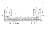
- FIG. 1 is a schematic cross-sectional view of an analysis device in the analysis kit according to the present embodiment.
- FIG. 2 is a schematic diagram illustrating a state in which a mixed solution of a sample and a reagent is injected into the analysis device.
- FIG. 3 is a schematic diagram illustrating a state in which the sealing liquid is injected into the analysis device.
- the analysis kit 1 includes an analysis device 2, beads 14, a reagent 15, and a sealing liquid 17.
- the analysis kit 1 which concerns on this embodiment, it is not essential that the bead 14 is included.
- the analysis kit 1 according to the present embodiment may detect the substance to be measured through the beads 14.
- the analysis kit 1 does not include the beads 14, the analysis kit 1 is introduced into the analysis kit 1 without using the beads 14.
- the substance to be measured may be directly analyzed.
- the object to be analyzed by the analysis kit 1 according to the present embodiment is a sample such as a nucleic acid.
- the analysis kit 1 according to the present embodiment can be used for quantifying nucleic acids.
- the analysis device 2 includes a base portion 3 and a cover portion 7.
- the base portion 3 includes a substrate 4 and a micropore array layer 5 formed on the substrate 4.
- the substrate 4 has, for example, a plate shape with a substantially uniform thickness.
- the substrate 4 is made of a substantially transparent material.
- resin or glass can be applied.
- the substrate 4 may be made of polystyrene or polypropylene.
- substrate 4 should just have the rigidity of the grade which is not damaged at the time of handling by the apparatus which conveys the analysis device 2, or an operator's manual work.
- the micropore array layer 5 is a layer formed by arranging a plurality of through holes.
- the layer thickness of the microhole array layer 5 is, for example, 3 ⁇ m.
- An interval of, for example, 100 ⁇ m is provided between the microhole array layer 5 and the cover portion 7 facing the microhole array layer 5.
- the material of the microhole array layer 5 may be resin, glass, or the like. As a material for the micropore array layer 5, a hydrophobic resin that is compatible with the sealing liquid (having high affinity with the sealing liquid) may be used.
- the material of the microhole array layer 5 may be the same as the material of the substrate 4 or may be different from the material of the substrate 4.
- the microhole array layer 5 may be integrated with the same material as the substrate 4. Further, the microhole array layer 5 may be integrally formed of the same material as the substrate 4.
- Examples of the material of the micropore array layer 5 formed from a resin include cycloolefin polymer, cycloolefin copolymer, silicon, polypropylene, polycarbonate, polystyrene, polyethylene, polyvinyl acetate, fluororesin, and amorphous fluororesin. . These materials shown as examples of the microhole array layer 5 are merely examples, and the material of the microhole array layer 5 is not limited thereto.
- the hydrophobicity in the present embodiment means that the contact angle between the hydrophobic material in the contact angle test and the fluorinated oil (product name FC-40, the standard solution for hydrophobicity evaluation according to the present embodiment) is 25 ° or less. Defined as being in range.
- the contact angle with the fluorinated oil is 10 ° or less.
- the contact angle with the fluorinated oil of cycloolefin polymer (COP), which is a hydrophobic resin is 10 It is about °.
- COP cycloolefin polymer
- the microhole array layer 5 may be directly formed on the substrate 4, or a member on which the microhole array layer 5 is formed is bonded or welded. It may be fixed to the substrate 4 by means.
- the microhole array layer 5 is formed by laminating a member as a material of the microhole array layer 5 on the substrate 4 and patterning a part of this member until the substrate 4 is exposed.
- the micropore array layer 5 is formed by patterning the solid pattern of the hydrophobic film laminated on the substrate 4 by processing such as etching, embossing, or cutting. Is done.
- the portion where the microhole array layer 5 is removed and the substrate 4 is exposed becomes the bottom surface 6a, and the plurality of accommodating portions 6 whose side surfaces are the microhole array layer 5 surrounding the portion where the substrate 4 is exposed are microhole arrays. Formed in layer 5.
- the accommodating portion 6 has a major axis of 7 ⁇ m and a minor axis of 3.5 ⁇ m, for example.
- the depth of the accommodating part 6 is 3 ⁇ m, for example.
- the accommodating part 6 is formed in the hollow column shape whose cross section is an ellipse.
- the opening shape of the accommodating part 6 is not specifically limited.
- the distance (pitch) between the center lines of the plurality of accommodating portions 6 only needs to be larger than the major axis of each accommodating portion 6.
- the center line of the housing portion 6 here refers to a line that passes through the center of the opening of the housing portion 6 and is parallel to the depth direction of the housing portion 6.
- the size of the interval (gap) between the storage units 6 is set according to the resolution with which each storage unit 6 can detect signals independently.
- Each accommodating portion 6 is arranged so as to have a triangular lattice shape with respect to the microhole array layer 5.
- sequence method of each accommodating part 6 is not specifically limited.
- the through-hole formed in the microhole array layer 5 and the surface of the substrate 4 form a bottomed cylindrical minute accommodating portion 6 having the substrate 4 as the bottom surface 6a.
- the volume of the accommodating part 6 may be set as appropriate. When the volume of the container 6 is small, the reaction time until signal detection becomes possible is short.
- the volume of the accommodating part 6 can be 100 picoliters or 100 picoliters or less as an example. More specifically, the volume of the container 6 is such that when the purpose is to reduce the time required to saturate the signal and generate a sufficient signal, the molecule to be analyzed is one in one container 6. It is set based on the amount of liquid that is less than one.
- micropore array layer 5 may be colored.
- the micropore array layer 5 when the micropore array layer 5 is colored, when measuring light such as fluorescence, light emission, absorbance, etc. in the housing 6, light from the other housing 6 adjacent to the housing 6 to be measured. The influence of is reduced.
- the accommodating part 6 formed by the micropore array layer 5 may have a hydrophobic part at the upper part of the accommodating part 6, and may have a colored part at a position closer to the bottom surface 6a of the accommodating part 6 than the hydrophobic part. .
- autofluorescence and noise when measuring fluorescence from the substrate 4 side are reduced, and acquisition of a fluorescence signal is facilitated.
- the transmission of the storage section 6 compared to the case where the position close to the bottom surface 6a of the storage section 6 is transparent. Since the light spot and the light transmission property change, it is easy to focus on the accommodating portion 6 of the micropore array layer 5.
- the colored portion of the storage unit 6 may be formed of, for example, metal vapor deposition or photoresist.
- the micropore array layer 5 When the micropore array layer 5 is integrally formed with the substrate 4, the micropore array layer 5 corresponds to the accommodating portion 6 by performing processing such as etching, embossing, or cutting on the substrate 4. To be formed.
- the micropore array layer 5 may have a hydrophobic part and a hydrophilic part.
- the part which becomes the inner peripheral surface of the accommodating part 6 in the micropore array layer 5 may be formed to be hydrophilic, and the other part in the microhole array layer 5 may be formed to be hydrophobic. .
- the sample 16 and the reagent 15 are unlikely to adhere to the flow path 9.
- the micropore array layer 5 may be subjected to a hydrophilic treatment so that the liquid easily enters the flow path 9 when various liquids are allowed to flow between the micropore array layer 5 and the cover portion 7.
- a hydrophilic treatment method can be appropriately selected from methods such as oxygen plasma treatment and ozone water treatment.
- the micropore array layer 5 is water-repellent when the sealing liquid 17 is fed. It may be made to become.
- the micropore array layer 5 can be made of a material having a water repellent material or a material to which a water repellent is added in advance and then a hydrophilic film is applied.
- the formation of the hydrophilic film can be selected from methods such as lithography and printing.
- a hydrophilic film is applied to the water-repellent micropore array layer 5, when the mixed solution of the sample 16 and the reagent 15 is first fed to the flow path 9, the surface of the micropore array layer 5 is hydrophilic. Therefore, it is easy to hold the liquid in the flow path 9, and when the hydrophilic film or the hydrophilic substance contained in the hydrophilic film is dissolved in the mixed solution of the sample 16 and the reagent 15, the water-repellent microarray layer is exposed. Thus, a state suitable for feeding the oil-based sealing liquid 17 is obtained.
- the surface of the substrate 4 may be hydrophilic and the micropore array layer 5 may be hydrophobic. In this case, the liquid mixture of the sample 16 and the reagent 15 is easily held on the surface of the substrate 4 that forms the bottom surface 6 a of the storage unit 6.
- an aqueous liquid can be easily held in the accommodating portion 6.
- a hydrophobic part and a hydrophilic part can be formed on the surface.
- the cover part 7 is bonded to the base part with a gap between the cover part 7 and the micropore array layer 5.
- the cover part 7 is arrange
- An additive such as a pigment may be added to the cover portion 7 in order to reduce autofluorescence. Since the analysis device 2 according to this embodiment is used to detect fluorescence or phosphorescence, it is preferable that the cover unit 7 does not substantially have autofluorescence.
- the cover part 7 is formed by injection molding or the like, not only the pigment dispersed in the resin in order to reduce autofluorescence, but also various dyes dissolved in the resin can be used as the colored component.
- the dye can be exemplified by various dye methods. Specific examples include direct dyes, basic dyes, cationic dyes, acid dyes, mordant dyes, acid mordant dyes, sulfur dyes, vat dyes, naphthol dyes, disperse dyes, and reactive dyes. In particular, when dyeing a resin, a disperse dye may be selected.
- the cover part 7 and the base part 3 are connected via a spacer 13. Thereby, a space created between the cover part 7, the base part 3, and the spacer 13 becomes the flow path 9.
- the material of the spacer 13 is not particularly limited.
- the spacer 13 has a certain thickness by, for example, laminating a double-sided pressure-sensitive adhesive tape in which an acrylic pressure-sensitive adhesive is laminated on both surfaces of a core material film formed of silicone rubber or an acrylic foam, or an adhesive. Can be appropriately selected and used as the spacer 13.
- the material of the spacer 13 may be resin, metal, paper, inorganic material such as glass, or the like.
- a member that does not easily react with the liquid to be fed can be selected as appropriate.
- a hydrophilic material may be used for a part of the spacer 13 or a hydrophilic process may be performed in order to facilitate introduction of the liquid to be fed into the flow path 9.
- the cover 7 and the microhole array layer 5 are hydrophobic, and only the double-sided adhesive tape of the spacer 13 can be made hydrophilic.
- the cover part 7 has a through-hole part that constitutes an inlet 8 to the flow path 9 and an outlet 10 from the flow path 9.
- the cover unit 7 includes a liquid injection unit 11 that communicates with the inlet 8 and a waste liquid storage unit 12 that communicates with the outlet 10.
- the liquid injection unit 11 communicates with the inlet 8 of the flow path 9 in order to send the mixed liquid of the sample 16 and the reagent 15, the sealing liquid 17, and the like from the inlet 8 of the flow path 9 into the flow path 9. It has a container shape.
- the inner surface of the liquid injection part 11 has a tapered shape so that the diameter gradually increases as the distance from the inlet 8 of the flow path 9 increases.
- the inner surface shape of the liquid injection part 11 is based on the tip shape of a pipette tip, a nozzle, or the like that dispenses a liquid such as a mixed solution of the sample 16 and the reagent 15 or a sealing liquid 17, and the like.
- pouring part 11 may be able to be connected now to the syringe for sending the liquid mixture of the sample 16 and the reagent 15, the sealing liquid 17 grade
- the waste liquid storage unit 12 is connected to the outlet 10 of the flow path 9.
- the volume of the waste liquid storage unit 12 is larger than the volume of the flow path 9. For this reason, even if the sealing liquid 17 is injected into the analysis device 2 so as to push out all of the sample 16 and the reagent 15 from the flow path 9, the sample 16 and the reagent 15 do not overflow from the waste liquid storage unit 12.
- the shortest distance L1 between the waste liquid storage unit 12 and the storage unit 6 is 2 mm or more along the flow path 9. In the present embodiment, the shortest distance between the accommodating portion 6 located closest to the outlet 10 of the channel 9 (the boundary between the channel 9 and the waste liquid storage unit 12) and the outlet 10 of the channel 9 in the plurality of accommodating portions 6.
- the distance (straight line distance) is configured to be 2 mm or more. When the flow path 9 is bent, the shortest distance between the waste liquid storage unit 12 and the storage unit 6 may be a distance measured by bending according to the bent state of the flow path 9.
- the volume of the waste liquid storage unit 12 is configured to be a volume capable of storing a surplus portion of the mixed solution of the sample 16 and the reagent 15 that has not entered the storage unit 6 and a part of the sealing liquid 17.
- the volume of the waste liquid storage unit 12 is, for example, 100 to 1000 ⁇ L, preferably 150 to 500 ⁇ L, and more preferably 200 to 300 ⁇ L.
- the waste liquid storage unit 12 may have two types, for example, a structure for waste liquid with a small amount of waste liquid such as the detection reagent 15 and a structure for waste liquid with a large amount of waste liquid such as the sealing liquid 17.
- the two types of waste liquid structures may have a double structure.
- the structure for waste liquid with a small amount of waste liquid may have a shape capable of storing a small amount of waste liquid by, for example, making the structure of the outlet 10 of the flow path 9 V-shaped.
- the waste liquid storage unit 12 may be provided with a lid so that the waste liquid does not leak out.
- the structure serving as the lid may be made of, for example, plastic or metal.
- cover may be seals, such as a film.
- cover is comprised from thermosetting resins, such as sponges, such as a polyurethane and polyvinyl alcohol, an amino resin, and a melamine resin, and can cover the waste liquid storage part 12 by heating later. It may be like this.
- An absorbent may be disposed in the waste liquid storage unit 12 so that the waste liquid can be absorbed.
- the waste liquid storage section 12 is positioned in the vertical direction of the flow path (positioned above the flow path 9), but the waste liquid storage section 12 is positioned in the horizontal direction of the flow path. May be located. That is, the waste liquid storage unit 12 may be provided on the side surface of the analysis device 2 in FIGS.
- the waste liquid storage unit 12 When the waste liquid storage unit 12 is arranged in the horizontal direction of the flow path, the sample that is not stored in the microhole array can be moved in the observation plane direction (horizontal direction).
- the analysis device 2 can be flattened (thickness can be reduced), so it is easy to carry and also interferes with the apparatus. Can be reduced.
- the arrangement of the waste liquid storage unit is not limited to the vertical direction of the flow channel and the horizontal direction of the flow channel, and is disposed obliquely above the flow channel, diagonally below the flow channel, etc., as long as it does not interfere with sample analysis and detection. However, it is not limited to the illustration of this embodiment.
- the base portion 3 and the cover portion 7 are joined in this manner, so that a plurality of storage portions 6, a flow path 9, a liquid injection portion 11, and a waste liquid storage portion. 12 and.
- the beads 14 can bind to the analysis target and have a specific gravity greater than that of the solvent in the mixed solution of the sample 16 and the reagent 15.
- a bead 14 that can be efficiently dropped into the accommodating portion 6 by gravity may be selected.
- the beads 14 containing a metal may be used as beads 14 for capturing an analysis target.
- the beads 14 include, for example, beads 14 containing at least one metal from metals such as ferrite, iron, copper, gold, silver, platinum, nickel, cobalt, tin, zinc, magnesium, calcium, and aluminum. May be.
- the beads 14 containing ferrite or magnets may be used to guide the beads 14 to the housing portion 6 with a magnet. By using magnetic beads, the beads 14 can be drawn into the housing portion 6 by magnetic force.
- the beads 14 made of resin may be selected as the beads for capturing the analysis target and trapped in the accommodating portion 6 using centrifugal force.
- any material may be selected from resins such as polystyrene, polyethylene, polyester, and polyterephthalate.
- the surface of the bead 14 may be labeled with a DNA probe.
- an antibody label may be applied to the beads 14.
- the shape of the beads 14 may be any size as long as the beads 14 can be accommodated in the accommodating portion 6, and from the opening side of the accommodating portion 6 when one bead 14 is accommodated in one accommodating portion 6. As seen, it is preferable that the shape of the opening of the accommodating portion 6 and the shape of the beads 14 are dissimilar. Since the substance itself that is the analysis target is dispersed in the solvent, it is difficult for the analysis target to enter the accommodating portion 6 if the analysis target remains dispersed in the solvent. In the present embodiment, the analysis target can be captured by the beads 14 having a specific gravity higher than that of the solvent, and the analysis target can be stored in the storage unit 6 together with the beads 14.
- the beads 14 can be of any size as long as the size of the beads 14 can be fixed to the accommodating portion 6, but is preferably 0.1 ⁇ m to 20 ⁇ m. The reason is that it is expected that it is difficult to optically detect the beads 14 when the size of the beads 14 is smaller than 0.1 ⁇ m. Further, if the bead 14 is larger than 20 ⁇ m, the surface area of the bead 14 becomes small, and there is a concern that the hybridization efficiency may be lowered due to a decrease in the number of contact between the probe for capturing the nucleic acid on the bead 14 and the nucleic acid. That is, when the size of the beads 14 is in the range of 0.1 ⁇ m to 20 ⁇ m, optical observation is easy and sufficiently high hybridization efficiency can be obtained.
- the size of the beads 14 may be a size other than the above preferred range (0.1 to 20 ⁇ m) corresponding to the shape of the accommodating portion 6.
- the reagent 15 (see FIG. 2) is sent from the liquid injection unit 11 of the analysis device 2 to the storage unit 6 through the flow path 9.
- the reagent 15 contains an enzyme and a buffer solution.
- the enzyme contained in the reagent 15 corresponds to the content of the biochemical reaction in order to perform a biochemical reaction such as an enzymatic reaction with respect to a template nucleic acid related to the analysis target.
- a biochemical reaction such as an enzymatic reaction with respect to a template nucleic acid related to the analysis target.
- the biochemical reaction with respect to the template nucleic acid is, for example, a reaction in which signal amplification occurs under conditions where the template nucleic acid is present.
- the reagent 15 is selected according to a method capable of detecting a nucleic acid, for example.
- the reagent 15 used in the Invader (registered trademark) method, the LAMP method (registered trademark), the TaqMan (registered trademark) method, the fluorescent probe method, and other methods is the reagent 15 according to this embodiment. included.
- the reagent 15 when a specific gene is to be analyzed (detected), the template nucleic acid itself or a part of the template nucleic acid is to be analyzed.
- the buffer solution is a liquid in which various additives are dissolved in a solvent so as to promote the enzyme reaction in a state where the sample 16 and the reagent 15 are mixed.
- the composition of the buffer may be appropriately selected from known compositions depending on the type of biochemical reaction.
- the reagent 15 may contain an additive such as a surfactant.
- a surfactant By adding a surfactant to the aqueous reagent 15, the beads 14 are dispersed again, so that it becomes easy to accommodate one bead 14 in the one accommodating portion 6. At this time, the beads 14 may be prevented from aggregating by stirring the mixed solution using a pipette.
- the reagent 15 may contain an additive for preventing deterioration of fluorescence to be detected.
- an additive for preventing deterioration of fluorescence to be detected.
- fluorescence may deteriorate due to the influence of active oxygen or the like
- a scavenger reagent, glucose oxidase, or the like may be added to the reagent 15 in order to prevent this.
- the reagent 15 necessary for the reaction may be filled in a bottle, but if the reagent 15 is used a plurality of times from the same bottle, erroneous analysis due to contamination may occur. In order to solve this problem, it is also possible to fill a bottle with an amount of reagent 15 that can be used once and use a bottle that can be used once.
- the shape of the bottle may be a shape in which the cap 15 is opened and the reagent 15 is used, a shape in which the seal 15 is removed and the reagent 15 is taken out, or a shape in which the reagent 15 is sucked by inserting a chip or the like into the lid.
- the reagent 15 may be filled in the container 6 from the beginning instead of filling the reagent 15 in a bottle or the like.
- the reagent 15 may be dried and solidified, or a lid may be provided so that the reagent 15 is filled in a liquid state and does not evaporate.
- the filling amount of the reagent 15 is not particularly limited, but the concentration can be adjusted according to the amount of the sample 16 to be mixed. For example, when an equal amount of the sample 16 is mixed with the reagent 15, the concentration of the reagent 15 can be made twice the final concentration.
- the sealing liquid 17 (see FIG. 3) is a liquid that is supplied to the flow path 9 in order to individually seal the plurality of storage units 6.
- the sealing liquid 17 is a liquid having a composition that does not mix with the sample 16 and the reagent 15.
- the sealing liquid 17 is preferably oily.
- the sealing liquid 17 is a solution that can be sent to the flow path 9 from the liquid injection section 11.
- the oil-based sealing liquid 17 for example, mineral oil, silicone oil, chloroform, squalene, hexadecane, fluorinated liquid FC-40, or the like can be used.
- the specific gravity of the sealing liquid 17 is higher than the specific gravity of the reagent 15 excluding the beads 14.
- Sealing liquid 17 may not be an oily liquid.
- the sealing liquid 17 that is not an oily liquid include a thermosetting resin and a photocurable resin.
- the viscosity of the sealing liquid 17 is, for example, 0.5 to 500 CS, preferably 0.7 to 200 CS, and more preferably 0.8 to 100 CS.
- Sealing liquid 17 may contain an additive in order to reduce autofluorescence. Since the method to be described later uses fluorescence or phosphorescence, the sealing liquid 17 preferably has substantially no autofluorescence.
- “substantially does not have autofluorescence” means that the sealing liquid 17 has no or no autofluorescence of the wavelength used for detection of the experimental result, but influences detection of the experimental result. It means that it is weak enough not to give. For example, if the autofluorescence is about 1/2 or less and 1/10 or less compared to the fluorescence of the detection target, it can be said that it is so weak that it does not affect the detection of the experimental result.
- Examples of the additive added to the sealing liquid 17 include organic or inorganic pigments.
- black pigments are carbon black, acetylene black, iron black, yellow pigments are chrome yellow, zinc yellow, ocher, hansa yellow, permanent yellow, benzine yellow, orange pigments are orange lake, molybdenum Orange, benzine orange, red pigments are red, cadmium red, antimony vermilion, permanent red, risor red, lake red, brilliant scarlet, thioindigo red, blue pigments are cluster, cobalt blue, phthalocyanine blue, ferrocyan blue
- Examples of indigo and green pigments include chrome green, viridian naphthol green, and phthalocyanine green.
- the pigment dispersed in the sealing liquid 17 can be used as the colored component.
- the dye can be exemplified by various dye methods. Specific examples include direct dyes, basic dyes, cationic dyes, acid dyes, mordant dyes, acid mordant dyes, sulfur dyes, vat dyes, naphthol dyes, disperse dyes, and reactive dyes. In particular, when dyeing a resin, a disperse dye is often selected.
- a surfactant may be added to the sealing liquid 17.
- a surfactant By adding a surfactant to the sealing liquid 17, the sealing efficiency can be increased.
- the type and concentration of the surfactant are not particularly limited, but can be set in view of compatibility with the reagent 15 and the material of the micropore array layer 5 and is preferably in the range of 0.001% to 10%.
- the sealing liquid 17 the oil-based sealing liquid 17 and the sealing liquid 17 composed of the thermosetting resin or the photocurable resin can be used in combination.
- a sealing liquid composed of a thermosetting resin after feeding an oil-based sealing liquid, noise when observing fluorescence can be reduced.
- the analysis method according to the present embodiment will be described by taking as an example the case where the analysis device 2 is used. Note that it is not essential to use the analysis device 2 described above for the analysis method.
- the analysis target is a nucleic acid and the concentration of the nucleic acid is measured will be described.
- the beads 14 and the sample 16 including the analysis target are mixed.
- the nucleic acid that is the analysis target is captured on the beads 14 by hybridization.
- the nucleic acid contained in the sample 16 includes nucleic acids other than the nucleic acid to be analyzed. Since the beads 14 are modified with a probe complementary to the nucleic acid to be analyzed, the nucleic acid to be analyzed can be specifically captured.
- the nucleic acid capturing probe bound on the beads 14 for example, an arbitrary one can be selected from nucleic acids such as DNA, RNA, BNA and PNA that form a complementary strand with the target nucleic acid.
- the target nucleic acid is double-stranded.
- the method can be selected from a method using alkali denaturation, a method using heat denaturation, or a method using enzymes.
- a thermal cycler may be used as a method by thermal denaturation. The reason for using the thermal cycler is to efficiently capture the nucleic acid of the target sequence on the beads 14.
- a tube having a structure in which thermal convection is likely to occur may be used in order to further increase the hybridization efficiency.
- a structure in which thermal convection is likely to occur for example, the lower part of the tube is formed thin, the upper part is formed thicker, and the thermal distribution of the solution in the tube may be changed to facilitate thermal convection.
- the heat distribution of the solution may be changed to cause thermal convection.
- the lower portion of the tube may be made of a material that easily transmits heat
- the upper portion may be made of a material that hardly transfers heat.
- buttons may be attached to one device, and each button may be adjusted to a temperature necessary for the reaction.
- a thermal cycler or a hot plate with a plurality of buttons a plurality of hot plates may be prepared and set to necessary temperatures, respectively, and hybridization may be performed. Hybridization may be performed while changing the temperature with a single hot plate.
- the hybridization efficiency may be increased by stirring instead of the heating operation.
- the stirring speed can be selected from 600 rpm to 3000 rpm, but preferably 600 rpm to 2000 rpm in order to prevent nucleic acid damage.
- the stirring time may be any time, but may be stirred overnight if the hybridization efficiency is poor.
- the hybridization solution is put in a container with a magnet and reacted while rotating using a hot plate stirrer or a normal stirrer.
- the hybridization reaction can be carried out while mixing the hybridization solution.
- a condition for increasing the Reynolds number that is, a condition for generating turbulent flow is selected so that the beads 14 are easily redispersed and the agitation is facilitated.
- the Reynolds number is preferably about several hundred to 1,000.
- the bead 14 After the bead 14 captures the object to be analyzed, the bead 14 is recovered and mixed with the reagent 15. For example, when magnetic beads are used, after hybridization, the beads 14 are collected at the bottom of the tube using a magnetic stand, and the supernatant is removed by a pipette. As another method, after the solution containing the hybridized beads is sucked into the pipette tip, the magnet is applied to the pipette tip, and only the liquid is discharged in a state where the beads 14 are captured. Thereafter, the detection reagent 15 may be aspirated, the magnet may be removed, the beads 14 and the reagent 15 may be stirred, and then the reagent 15 containing the beads 14 may be introduced into the detection device.
- the detection reagent 15 may be aspirated, the magnet may be removed, the beads 14 and the reagent 15 may be stirred, and then the reagent 15 containing the beads 14 may be introduced into the detection device.
- the magnet used may be applied from the side of the pipette tip. It is also possible to use a donut-shaped magnet that can be attached to a pipette tip.
- the beads 14 are collected by centrifugation and mixed with the detection reagent 15. In this case, the beads 14 may be separated using a filter having a pore diameter smaller than the diameter of the beads 14.
- the beads 14 may be washed using a washing solution.
- this mixed solution is manually applied to the liquid injection unit 11 of the analysis device 2 as shown in FIG. inject.
- the solution containing the analysis object is introduced from the liquid injection part 11 of the empty analysis device 2, a small amount of solution that fills only a part of the flow path 9 is introduced, and then the sealing liquid 17 is introduced.
- the method of accommodating the mixed solution of the sample 16 and the reagent 15 in the accommodating unit 6 is not limited to the above method.
- the inside of the analysis device 2 is filled with a pre-buffer in advance, and a mixed solution of the sample 16 (bead 14 capturing the analysis target) and the reagent 15 is introduced from the liquid injection unit 11 to replace the pre-buffer.
- the mixed solution may be introduced into the storage unit 6.
- the solution may be introduced from the liquid injection unit 11 of the empty analysis device 2 and the mixed solution may be introduced into the storage unit 6 by applying a centrifugal force to the analysis device 2.
- the liquid mixture may be introduced into the storage unit 6 by continuously introducing a solution or a pre-buffer in which the air in the analysis device 2 can be dissolved from the liquid injection unit 11.
- the inlet 8 and the outlet 10 of the flow path 9 are sealed.
- a method for sealing a type in which a plug is plugged with a lid or a type in which the upper surface of the cover part 7 is sealed with a film seal may be used.
- the beads 14 may be first introduced into the storage unit 6 of the analysis device 2, and then the reagent 15 may be fed to the analysis device 2. In this case, the bead 14 and the reagent 15 come into contact with each other in the storage unit 6 and a biochemical reaction can be started.
- the operation of injecting the mixed liquid from the liquid injection unit 11 to the flow path 9 may be performed by a pipette or a dispensing device.
- the pipette tip from which the solution has been measured is inserted into the inlet 8, and the solution is naturally injected by removing the pipette tip from the pipetter, so that the liquid feeding speed is kept constant with no manual difference.
- it is desirable that the liquid level of the solution in the pipette tip is above the flow path 9 of the analysis device 2.
- the quantity of a solution is more than the quantity which can satisfy
- the sealing liquid 17 is introduced into the flow channel 9.
- the accommodating part 6 is sealed separately.
- the beads 14 accommodated in the accommodating part 6 remain in the accommodating part 6 by gravity, and the reagent 15 accommodated in the accommodating part 6 remains in the accommodating part 6 because the inside of the accommodating part 6 is hydrophilic.
- the sealing liquid 17 By introducing the sealing liquid 17 into the flow path 9 until the sealing liquid 17 enters the waste liquid storage section 12, excess reagent 15 and the sample 16 in the flow path 9 are pushed into the waste liquid storage section 12.
- the specific gravity of the sealing liquid 17 is higher than that of the reagent 15 except for the beads 14, so that the mixed liquid of the reagent 15 and the sample 16 is overlaid on the sealing liquid 17. .
- a treatment for causing a biochemical reaction such as a signal amplification reaction is performed.
- a biochemical reaction such as a signal amplification reaction
- the fluorescence signal can be detected.
- phosphorescence may be detected instead of fluorescence.
- the invader reaction is an isothermal reaction in which a reaction is performed for a predetermined time under a predetermined temperature condition. For this reason, when performing an invader reaction, the analysis device 2 is left still in the chamber where temperature was kept constant. Further, the analysis device 2 may be placed on a hot plate whose temperature is kept constant. As a heating device such as a hot plate for heating to the reaction temperature, a device with a timer may be used.
- the reaction time of the detection reagent 15 may be lengthened, or the fluorescent substance concentration in the detection reagent 15 may be increased. Or you may raise the sensitivity of a detection apparatus.
- the beads 14 used may be fluorescent beads that emit fluorescence having a wavelength different from the wavelength of the fluorescence generated by the reaction between the analysis target and the detection reagent 15. In this case, the beads 14 can be counted by fluorescence detection.
- Detection of fluorescence or phosphorescence can be performed using an apparatus such as a fluorescence microscope.
- the fluorescence microscope used in the present embodiment is connected to a camera for capturing a microscope image and a computer system in which software for analyzing the microscope image captured by the camera is installed.
- a microscope image including a plurality of storage units 6 in the field of view is taken, and the number of storage units 6 in which a signal amplification reaction has occurred is measured based on the presence or absence of fluorescence in the image.
- the number of the accommodating parts 6 in which the beads 14 that have captured the analysis object are included in the entire accommodating part 6 can be measured.
- the fluorescence observation method using the analysis device 2 may be a method in which the analysis device 2 is directly placed on a microscope, but in the case of a small analysis device 2, the analysis device 2 is prevented from falling from the stage of the fluorescence microscope.
- a jig with a refilling rod may be used.
- the jig may be a tape.
- the fluorescent microscope may have a recognition function. For example, in order to focus on the beads 14 in the storage unit 6, the focus can be once adjusted on the storage unit 6, and a certain amount can be finely moved up and down from the location to use the function to search for the beads 14. Further, an image processing / image recognition algorithm may be inserted so that the beads 14 are in focus.
- the registered image particularly how the beads 14 with out-of-focus, illumination unevenness, dirt, etc. are observed is made into an image database because the matching accuracy is improved.
- the position of the bead 14 and the accommodating portion 6 on the Z-axis in the focus direction is memorized in a state in which the edge is made to stand out with transmitted illumination, with a phase difference, and switched to fluorescent illumination to display the bead in a fluorescent image. It is desirable to increase the accuracy if a mechanism for confirming 14 and the accommodating portion 6 is used. It is also possible to lengthen the accommodating portion 6 to widen the focusable range and search for the beads 14.
- the analysis device 2 to be measured is set on the fluorescent microscope. It is also possible to reduce the restriction in the fluorescence microscope by lengthening the accommodating portion 6 vertically and widening the range that can be focused. If there is a difference in the thickness of the fluorescent filter of the fluorescent cube, consider combining the filters so that the optical path length does not change for each fluorescent filter, or even if the objective lens is finely moved to focus on each fluorescent cube Good. Or you may adjust with the optical element in which the optical path length which changes with a filter changes.
- the accommodating portion 6 may be lengthened vertically to increase the focus range (depth of field).
- a mercury lamp, a light emitting diode, or the like may be employed as a light source used in the fluorescence microscope.
- LED light sources have been sold for fluorescent microscopes. Still, there are not so many types of wavelengths, and not all LEDs are stronger excitation light sources than mercury lamps, but if the wavelengths match, strong excitation light that matches the excitation wavelength is possible, and the fluorescence intensity is also strong, It is possible to use a light source with little fluorescence deterioration, and it is possible to shorten the exposure time. If an appropriate filter that can cut the UV side and has a wide excitation light width is selected, the exposure time can be reduced because the excitation light becomes stronger.
- Image processing such as integration photography is performed so that even an objective lens having a magnification of 5 times can be counted. For example, when shooting with a camera having about 4 million pixels, the resolution is increased by changing to the 10 million pixel class. It is also possible to determine the photographing conditions from the photographing result of the low magnification objective lens. For example, if the image is taken with a low-magnification objective lens and the brightness of the entire image is high, the target density is high, so it is possible to reduce the number of shots without observing a large number of storage units 6, and low magnification If the overall brightness is low when shooting with the objective lens, the number of shots can be increased because the target density is low. It is also possible to switch the shooting to a high magnification after shooting at a low magnification.
- the beads 14 and fluorescence may be photographed separately. You may image
- the bead 14 may measure only one field (or several fields) to determine the overall encapsulation rate. In this case, the measurement time can be shortened.
- the bead 14 may have a constant encapsulation rate regardless of the number of experiments, and may be calculated with a default encapsulation rate without performing measurement. In this case, the measurement time can be further shortened.
- the camera that captures the microscope image can be appropriately selected from known cameras including a CCD or a CMOS image sensor. If the magnification of the microscope is 10 times, the field of view becomes narrow, but if the camera has a large CMOS sensor chip, the field of view range becomes large. Since the magnification is reduced, the field of view is widened.
- the amount of data can be reduced by lowering the number of gradations during imaging. Further, the data amount may be reduced by increasing the number of gradations only in necessary portions or excluding unnecessary portions from the imaging range.
- the performance of the camera itself is about 12 bits of gradation, it is possible to prevent digits from being lost by calculating with 14 bits. Note that the number of gradations can be set to 8 bits if only the final result is obtained. In addition, it is desirable to have a redundant server of RAID 1 to 5 and store data in this server.
- whether or not the container 6 emits fluorescence may be a predetermined value as a threshold value.
- the transmittance of the excitation light and the lens on the camera side is weak in the periphery, it may be corrected in advance.
- a solid object such as barium carbonate, which is a solid object, is often used as a reflective object, so it is possible to shoot the standard reflector and correct the amount of light loss using software. is there.
- a method of connecting and correcting the center of the image, that is, the image at the center of the lens, and calculating the ratio of light reduction in the peripheral portion can be used as one of the correction methods.
- Measures such as not using an image with foreign matter or omissions are also necessary, and points that shine in the same size as the housing 6 can be removed by image processing.
- the size of the accommodating part 6 is 5 ⁇ m
- the shining point of the size less than 5 ⁇ m or larger than 5 ⁇ m is not regarded as the accommodating part 6 and can be excluded from the measurement target.
- the positions of the plurality of storage units 6 in the microscope image are stored in advance as patterns in a computer system attached to the microscope apparatus.
- the colored sealing liquid 17 By using the colored sealing liquid 17, autofluorescence of the analysis device 2 and irregular reflection in the analysis device 2 can be suppressed.
- the analysis device 2 can also be measured after measuring the solid film for calibration (entirely formed film) and measuring the focal length.
- autofluorescence can be suppressed to a low level by performing excitation exposure by masking so that excitation light is not exposed except where necessary.
- the computer system automatically outputs the analysis result of the analysis object, for example, the mutation rate and the concentration when the analysis object is a nucleic acid.
- the result is used as a reference, and what is lacking as a condition is clearly displayed to prevent an erroneous result from being automatically generated.
- the fluorescence in the storage unit 6 in which the biochemical reaction has occurred is n times higher than the fluorescence in the storage unit 6 in which the biochemical reaction has not occurred. Since comparisons such as values cannot be made, it is also possible to adopt a method of using this as an error.
- the ratio of the accommodating part 6 in which the fluorescence intensity is higher than a specified value is 10% or more of the whole, for example, an error can be caused.
- a program may be provided that requests data each time it is difficult to determine whether it is an error by storing error data and constructing a database of error references.
- a mechanism for recognizing the possibility of an error may be provided.
- those that show a value higher than a predetermined multiple of the criterion are not included in the accommodating part 6 in which the biochemical reaction has occurred or in the accommodating part 6 in which the biochemical reaction has occurred (that is, ignored). It is also possible to adopt the method.
- the excitation light can be turned off and the previous image can be displayed, or the excitation light can be gradually increased from a weak point. . Even if the excitation light ends with a strong setting, if the sample is changed, it can start from a weak point. Or, in the case of strong light, the image is taken with the camera in conjunction with the excitation light ON. The sensitivity of the camera starts with exposure of maximum or about 1 second (initial setting can be set to 0.1 second, 5 seconds, or 10 seconds). During that time, the excitation light cannot be strengthened.
- an image without the bead 14 in advance and then take an image with the bead 14 and extract an image of the bead 14 based on the difference between the images. For example, when the focus is slightly shifted, the image is slightly tilted, the center is in alignment, the right is blurred by +, the left is blurred by-, and the lighting is uneven. As an image, an image of the housing 6 without the beads 14 may be registered.
- the bead 14 can be extracted and counted by an image processing algorithm that registers a reference image of the bead 14 and determines a similar one. If many examples are collected as an image database, the relevance rate can be increased. Depending on the wavelength of the fluorescence used when counting the accommodating portions 6 that emit fluorescence, another fluorescence wavelength may be easier to count. Alternatively, beads 14 that can be detected at other wavelengths may be selected and used.
- the analysis device 2 As described above, by using the analysis device 2 according to the present embodiment, it is possible to count the storage units 6 that emit fluorescence during fluorescence observation due to a biochemical reaction occurring in the storage unit 6.
- the mixed liquid and the sealing liquid 17 are agitated in the vicinity of the interface 18 between the mixed liquid of the sample 16 and the reagent 15 and the sealing liquid 17, or the solute in the mixed liquid is transferred to the sealing liquid 17. It may be possible to migrate. Since the mixture of the sample 16 and the reagent 15 undergoes a biochemical reaction that emits fluorescence, the mixture is in a state capable of emitting fluorescence in response to irradiation with excitation light. For this reason, if the surplus of the mixture of the sample 16 and the reagent 15 is located in the vicinity of the storage unit 6, it becomes difficult to distinguish the fluorescence due to the surplus and the fluorescence in the storage unit 6.
- the interface 18 between the mixed liquid and the sealing liquid 17 is the storage unit. It is in a position sufficiently away from 6. For this reason, in this embodiment, the solute due to the above stirring and transfer is less likely to affect the biochemical reaction in the container 6. Moreover, although the solute by the above stirring and transfer can emit fluorescence in response to the irradiation with excitation light, it is sufficiently separated from the housing portion 6 and thus hardly affects the fluorescence measurement.
- the reagent 15 stored in the waste liquid storage unit 12 is unlikely to interfere with the fluorescence observation in the storage unit 6, so that highly reproducible analysis is performed. be able to.
- the analysis kit 1 and the analysis device 2 according to the present embodiment do not require a separate device for collecting the waste liquid, and thus can be downsized as a whole.
- the specific gravity of the sealing liquid 17 is higher than the specific gravity of the reagent 15 excluding the beads 14, so that the surplus in the mixed liquid of the sample 16 and the reagent 15 is stored in the waste liquid storage unit 12. It is difficult to flow backward from the waste liquid storage unit 12 to the flow path 9 after the transition.
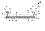
- FIG. 4 is a schematic cross-sectional view of an analysis device in the analysis kit according to the present embodiment.
- the analysis device 2 ⁇ / b> A according to this embodiment the shortest distance between the waste liquid storage unit 12 and the storage unit 6 does not have to be 2 mm or more along the flow path 9.
- the sample 16 and the reagent 15 are sealed with the sample 16 and the reagent 15 when the sample 16 and the reagent 15 are stored in the waste liquid storage unit 12 in a state of being layered on the sealing liquid 17.
- the shortest distance between the interface 18 with the liquid 17 and the container 6 is 2 mm or more along the flow path 9.
- the position of the interface 18 corresponds to the amount of the sealing liquid 17 injected from the liquid injection part 11. That is, in the present embodiment, an amount of the sealing liquid 17 necessary to make the shortest distance L2 between the interface 18 and the accommodating portion 6 be 2 mm or more along the flow path 9 is injected from the liquid injection portion 11. It is like that.
- the shortest distance L2 between the interface 18 and the container 6 in the present embodiment is, for example, the flow path 9 and the waste liquid from the container 6 to the interface 18 that is closest to the waste liquid storage unit 12 in the plurality of containers 6. It may be a distance measured along a straight line bent so as to be connected through the storage unit 12 in the shortest distance.
- the shortest distance between the interface 18 and the accommodating portion 6 may be a distance measured so as to pass through the center of the flow path 9.
- the injection of the sealing liquid 17 may be performed manually.
- the sealing liquid 17 may be injected by a system that automatically injects a predetermined amount of the sealing liquid 17.
- FIG. 4 shows an example in which the waste liquid storage unit 12 is positioned in the vertical direction of the flow path (located above the flow path 9), but the waste liquid storage unit 12 is positioned in the horizontal direction of the flow path. May be. That is, the waste liquid storage unit 12 may be provided on the side surface of the analysis device 2A in FIG.
- the sample that is not stored in the microhole array can be moved in the observation plane direction (horizontal direction). Even when the waste storage part 12 is arranged in the horizontal direction of the flow path, the interface 18 between the sample 16 and the reagent 15 and the sealing liquid 17 when stored in the waste liquid storage part 12 is formed.
- the shortest distance between the interface 18 and the accommodating portion 6 is preferably configured to be separated by 2 mm or more along the flow path 9.
- the analysis device 2A can be flattened (thickness can be reduced), so it is easy to carry and interferes with the apparatus. Can be reduced.
- the arrangement of the waste liquid storage unit 12 is not limited to the vertical direction of the flow path and the horizontal direction of the flow path. It may be arrange
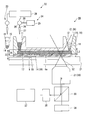
- FIG. 5 is a schematic diagram of an analysis apparatus (analysis system) according to the present embodiment.
- the analysis apparatus (analysis system) 20 according to the present embodiment shown in FIG. 5 is automatically performed using the analysis device 2 disclosed in the first embodiment and the analysis device 2A disclosed in the second embodiment.
- This is a device including a system for performing analysis. Below, the system which analyzes using the analysis device 2 disclosed by 1st Embodiment is demonstrated.
- the analysis device 2A disclosed in the second embodiment can be similarly used in the analysis system 20 of the present embodiment.
- the analysis system 20 includes a stage 21 for placing the analysis device 2, a liquid injection device 22 for injecting various liquids into the analysis device 2 on the stage 21, an optical system 30 including an objective lens 31, and an optical system.
- An imaging unit 35 connected to the system 30, a light source unit 36 that irradiates the accommodating unit 6 in the analysis device 2 through the optical system 30 with excitation light, and an analysis device 37 that analyzes an image captured by the imaging unit 35. Yes.
- the liquid injection device 22 has a first liquid injection part 23 for injecting the sample 16 and the reagent 15 into the analysis device 2 and a second liquid injection part 24 for injecting the sealing liquid 17 into the analysis device 2. is doing.
- the first liquid injection unit 23 a configuration of a known automatic dispensing device can be appropriately selected and employed.
- the first liquid injection unit 23 dispenses this mixed liquid from the container (not shown) accommodated in a state where the sample 16 and the reagent 15 are mixed to the liquid injection unit 11 of the analysis device 2.
- the first injection unit 23 cooperates with the apparatus (not shown) for performing the hybridization process disclosed in the first embodiment.
- the first injection part 23 The captured beads 14 may be mixed with the reagent 15 and injected into the analysis device 2.
- the second liquid injection unit 24 includes, for example, a tank 25, a pipe 26, a nozzle 27, a pump 28, and a control unit 29.
- the tank 25 and the nozzle 27 are connected by a tube, and a pump 28 is connected to the pipe 26.
- the control unit 29 determines the injection amount of the sealing liquid 17 corresponding to the configurations of the analysis device 2 and the optical system 30, drives the pump 28, and seals from the tank 25 to the analysis device 2 via the nozzle 27. Liquid 17 is fed.
- the optical system 30 can set the focal point of the objective lens 31 in the vicinity of the bottom surface 6a of each storage unit 6 of the analysis device 2 on the stage 21 and is used for observing fluorescence in each storage unit 6.
- the focal position 32 can be set on the bottom surface 6 a of each storage unit 6.
- a certain range (focal depth 33) is set around the focal position 32 in the optical axis direction of the objective lens 31. Imaging can be suitably performed.
- the imaging unit 35 has an image sensor for detecting fluorescence transmitted to the imaging unit 35 through the optical system 30.
- the imaging unit 35 captures the fluorescence image and outputs it to the analysis device 37.
- the light source unit 36 irradiates the analysis device 2 through the optical system 30 with excitation light having a wavelength corresponding to the type of fluorescent labeling substance used in the biochemical reaction using the analysis device 2.
- the analysis device 37 determines the presence or absence of fluorescence in the storage unit 6 of the analysis device 2 based on the image captured by the imaging unit 35. Furthermore, the analysis apparatus 37 measures the number of the accommodating units 6 emitting fluorescence among the accommodating units 6 in the analysis device 2, and calculates the concentration of the analysis target in the sample 16 injected into the analysis device 2.
- the control unit 29 stores data relating to the shape of the analysis device 2 and data relating to the focal depth 33 of the objective lens 31.
- the data relating to the shape of the analysis device 2 includes at least the position of the bottom surface 6a of the container 6 in the optical axis direction of the objective lens 31, the amount of liquid injected into the analysis device 2, and the surface position of the liquid in the waste liquid storage unit 12. It is the data which shows the relationship.
- the position of the bottom surface 6a can be based on, for example, the upper surface of the stage 21 (the surface on which the analysis device 2 is placed). Data indicating the relationship between the amount of liquid injected into the analysis device 2 and the surface position of the liquid in the waste liquid storage unit 12 is stored in the control unit 29 as a table, a calculation formula, or the like.
- the control unit 29 uses the information on the position of the bottom surface 6 a of the housing unit 6 and the depth of focus 33 of the objective lens 31 when the focal position 32 of the objective lens 31 is located on the bottom surface 6 a of the housing unit 6.
- the width of the in-focus range in the optical axis direction of the objective lens 31 is acquired. This range is determined in advance based on the lens data of the objective lens 31 so that, for example, the frequency of erroneous determination occurring when the presence or absence of fluorescence is determined using the analysis device 37 is equal to or less than a predetermined threshold. ing.
- the control unit 29 acquires a distance (fluorescence obtainable distance 34) from the bottom surface 6 a of the housing unit 6 to a boundary far from the objective lens 31 in a focused range.
- the control unit 29 determines that the distance L3 from the bottom surface 6a of the storage unit 6 to the surface position is as described above.
- the injection amount of the sealing liquid 17 is determined so that the distance L3 is preferably longer than the above-described fluorescence acquirable distance 34 so that the fluorescence acquirable distance 34 is greater than or equal to 34.
- the position of the interface 18 between the mixed liquid of the sample 16 and the reagent 15 and the sealing liquid 17 in the waste liquid storage unit 12 is accommodated in the optical axis direction of the objective lens 31.
- the distance from the bottom surface 6 a of the portion 6 is greater than the fluorescence obtainable distance 34.
- the analysis system 20 of this embodiment When the analysis system 20 of the present embodiment is used, when the injection of the sealing liquid 17 is completed, the surplus of the sample 16 and the reagent 15 and a part of the sealing liquid 17 supplied to the flow path 9 are stored in the waste liquid. Stored in the section 12 as waste liquid. The mixed solution of the sample 16 and the reagent 15 is overlaid on the sealing liquid 17 in the waste liquid storage unit 12. The position of the interface 18 between the mixed solution of the sample 16 and the reagent 15 and the sealing liquid 17 in the waste liquid storage unit 12 is farther from the bottom surface 6a of the storage unit 6 than the fluorescence obtainable distance 34 in the optical axis direction of the objective lens 31. In the position.
- the sample 16 and the reagent 15 stored in the waste liquid storage unit 12 are located outside the in-focus range in the optical system 30. Since the liquid mixture of the sample 16 and the reagent 15 in the waste liquid storage unit 12 includes the analysis object and the reagent 15, the liquid can be emitted in response to the irradiation of the excitation light. In this embodiment, when excitation light is irradiated to the liquid mixture in the waste liquid storage part 12 through the optical system 30, the liquid intensity in the waste liquid storage part 12 is at a position away from the focal position 32, so that the fluorescence intensity is low. . Furthermore, since the liquid mixture in the waste liquid storage unit 12 is not in focus, even if it emits fluorescence, it does not become a light spot on the image.
- the S / N ratio between the fluorescence in the storage unit 6 near the waste liquid storage unit 12 and the fluorescence in the waste liquid storage unit 12 is calculated in the storage unit 6 in the analysis device 37. It can be sufficiently increased to the extent that the presence or absence of fluorescence can be determined.
- the control unit 29 controls the injection amount of the sealing liquid 17 to increase the S / N ratio between the fluorescence in the storage unit 6 near the waste liquid storage unit 12 and the fluorescence in the waste liquid storage unit 12. be able to.
- the reagent 15 stored in the waste liquid storage unit 12 can perform a highly reproducible analysis that is unlikely to interfere with fluorescence observation in the storage unit 6, and the storage unit 6.
- the analysis device 2 can be downsized by shortening the distance from the waste liquid storage unit 12 to the waste liquid storage unit 12.
- FIG. 5 as in the first and second embodiments, the example in which the waste liquid storage unit 12 is positioned in the vertical direction of the flow channel (located above the flow channel) is shown.
- the waste liquid storage unit 12 may be located in the horizontal direction of the flow path. That is, the waste liquid storage unit 12 may be provided on the side surfaces of the analysis devices 2 and 2A in FIG.
- the sample that is not stored in the microhole array can be moved in the observation plane direction (horizontal direction).
- the interface 18 between the sample 16 and the reagent 15 and the sealing liquid 17 when stored in the waste liquid storage part 12 is formed.
- the shortest distance between the interface 18 and the accommodating portion 6 is preferably 2 mm or more along the flow path 9.
- the analysis devices 2 and 2A can be flattened (thickness can be reduced). Interference with the apparatus used for the operation can be reduced.
- the arrangement of the waste liquid storage unit 12 is not limited to the vertical direction of the flow path and the horizontal direction of the flow path. It may be arrange
- the analysis device 2 of this modification is used for an analysis that does not use the beads 14.
- the analysis object is introduced into the container 6 and the analysis is performed.
- pre-amplification may be performed before introducing the solution containing the analysis object into the analysis device 2.
- Preamplification may use the polymerase chain reaction (PCR). PCR may be performed from several cycles to several tens of cycles as necessary, preferably 10 cycles or more.
- PCR polymerase chain reaction
- reverse transcription PCR may be performed before introducing the solution containing the analysis target into the analysis device 2.
- amplification reactions may be carried out using commercially available tubes, but a site for performing pre-amplification may be provided in the analysis device 2. After the pre-amplification, the solution containing the amplification reagent 15 and the analysis target is sent to the analysis device 2, and after performing an amplification reaction in the analysis device 2, the detection reaction reagent 15 is added, and then the sealing liquid 17 And the detection reaction (signal amplification reaction) may be performed on the housing portion 6.
- the analysis may be performed by increasing the number of the analysis target existing in the storage unit 6 by using a plurality of devices.
- the analysis may be performed using a plurality of devices. Further, in this case, the solution containing the analysis target may be evaporated and then introduced into the device.
- the diameter of the accommodating portion 6 can be selected in the range of 100 nm to 100 ⁇ m, and is preferably 1 ⁇ m to 100 ⁇ m. This is because it is considered that it is difficult to hold the nucleic acid in the housing portion 6 when the diameter of the housing portion 6 is smaller than 1 ⁇ m. Moreover, if the diameter of the accommodating part 6 is larger than 100 ⁇ m, a plurality of nucleic acids will be contained in one accommodating part 6.
- the depth of the accommodating part 6 can be selected in the range of 100 nm or more and 100 ⁇ m or less, it is preferably 1 to 10 ⁇ m. If the depth of the accommodating part 6 is smaller than 1 ⁇ m, it becomes difficult to hold the nucleic acid in the accommodating part 6. Moreover, if the depth of the accommodating part 6 is larger than 100 ⁇ m, a plurality of nucleic acids may be contained in one accommodating part 6. When increasing the volume of the accommodating part 6, there is a concern about a decrease in the reaction rate. Therefore, by using the vertically long accommodating portion 6, even if the reaction rate decreases, the fluorescence signals in the observation direction can be integrated, and observation can be facilitated.
- the ratio of the depth and the diameter of the accommodating portion 6 is preferably 1: 1 or more. However, if the diameter becomes too small, observation with a camera becomes difficult, so it is necessary to determine the length in consideration of the length of the diameter.
- the ratio of the depth and the diameter of the accommodating portion 6 is more preferably 1: 2 or more.
- Example 1 ⁇ Production of analysis device> A base portion 3 having a thickness of 0.6 mm, made of cycloolefin polymer, and having 1 million holes with a diameter of 5 ⁇ m was produced by injection molding.
- a cover glass was placed on the base 3 as the cover 7 so that the gap with the base 3 was 100 ⁇ m.
- a spacer 13 made of an adhesive tape was disposed between the base 3 and the cover 7.
- nucleic acid is contained between the base body part 3 and the cover part 7 via the liquid injection part 11 using the first liquid injection part 23 of the liquid injection apparatus 22 in the analysis apparatus as shown in FIG.
- a non-aqueous liquid was fed as a replacement liquid, and the entire area of the hole having a diameter of 5 ⁇ m and the gap between the base portion 3 and the cover portion 7 was filled with the aqueous liquid.
- the composition of the aqueous liquid is 20 mM MOPS pH 7.5, 15 mM NaCl, 6.25 mM MgCl 2 .
- the artificial synthetic DNA was mixed so that the concentration of the artificial synthetic DNA was 3 pM so that one molecule could enter one of the holes of 5 ⁇ m in diameter formed in the base portion 3.
- a cylindrical micropore having a diameter of 5 ⁇ m and a height of 3 ⁇ m has a volume of 59 fL, and assuming that it follows a Poisson distribution, it is estimated that the artificially synthesized DNA concentration of 3 pM enters 10% of 1 million micropores.
- FC-40 SIGMA
- the distance L3 from the bottom surface 6a of the storage unit 6 to the interface 18 between the sample and reagent mixture and the sealing liquid in the waste liquid storage unit 12 is 0 mm (test A), 1 mm.
- Test A the distance L3 from the bottom surface 6a of the storage unit 6 to the interface 18 between the sample and reagent mixture and the sealing liquid in the waste liquid storage unit 12 is 0 mm (test A), 1 mm.
- Test B The following fluorescence observation measurement was performed under the conditions in which the injection amount of the sealing liquid 17 was changed so as to be 2 mm (Test C), 4 mm (Test D), and 8 mm (Test E).
- the analysis device of this example having 1 million independent nucleic acid detection reaction vessels was incubated for 15 minutes under the condition of 63 °, and the fluorescence microscope (the optical system 30, the objective lens 31, the light source unit 36 in FIG. 5) was incubated. , Corresponding to the imaging unit 35 and the analysis device 37), and the fluorescence intensity of each hole was observed.
- the post-reaction analysis device took a fluorescent image using a fluorescent microscope.
- control part of the fluorescence microscope was comprised so that the position of the some accommodating part in the analysis device mounted on the stage and the focal depth of the objective lens in a fluorescence microscope could be acquired.
- the depth of focus of the objective lens used in the fluorescence microscope according to Example 1 was 3 ⁇ m.
- test A in which the distance L3 is 0 mm, the number of nucleic acid detection reaction containers that emit fluorescence cannot be measured due to the influence of fluorescence emission of the sample present in the flow path.
- test B where the distance L3 is 1 mm, as in the test A, the influence of the background fluorescence emission, which is considered to be derived from the nucleic acid present in the waste liquid storage unit, is large, and the number of nucleic acid detection reaction containers emitting fluorescence is measured. could not.
- the influence of background fluorescence that is considered to be derived from the nucleic acid present in the waste liquid storage unit The number of the nucleic acid detection reaction containers that emit fluorescence could be measured without receiving the light.
- the number of nucleic acid detection reaction vessels that emit fluorescence is reproduced without being affected by background fluorescence that is thought to be derived from nucleic acids present in the waste liquid storage unit. It was possible to measure with good performance and with less influence of noise generation.
- 2 mm corresponds to the fluorescence obtainable distance 34 according to the analysis apparatus using the analysis device according to the present embodiment (strictly, the fluorescence obtainable distance 34 between 1 mm and 2 mm). It is considered that 2 mm corresponds to the threshold value with the fluorescence obtainable distance 34). That is, when the relationship of the fluorescence obtainable distance 34 (2 mm)> L3 is satisfied, it is difficult to measure the number of nucleic acid detection reaction containers that emit fluorescence. On the other hand, when the relationship of the fluorescence obtainable distance 34 (2 mm) ⁇ L3 was satisfied, it was confirmed that the number of nucleic acid detection reaction containers emitting fluorescence can be measured in this example.
- the distance L3 from the bottom surface of the container to the interface between the sample and reagent mixture and the sealing liquid in the waste liquid storage is 2 mm or more (more than the fluorescence acquisition distance). According to this, it was confirmed that the number of nucleic acid detection reaction vessels that emit fluorescence can be measured without being affected by background fluorescence emission that is thought to be derived from nucleic acids present in the waste liquid storage unit.
- the analysis device is used as an array device for nucleic acid quantification
- the analysis target using the analysis device is not limited to the nucleic acid.
- the analysis device according to the embodiment of the present invention can be applied to an array device for analyzing proteins, lipids, and sugar chains.
- the container is opened vertically (for the mixed solution).
- the analysis target in the sample is accommodated together with the beads in the container by containing beads having a specific gravity smaller than that of the solvent in the reagent. be able to.
- various liquids used for biochemical reactions may be sent to the flow path in advance, and the flow path may be filled with the solution.
- the detection reaction reagent can be filled in the analysis device in advance, the sealing liquid can be sent to the flow path after long-term storage, and then the measurement can be performed.
- the inlet and outlet between the micropore array layer and the cover part may be sealed with a lid material.
- the lid material may be a molded product such as plastic or metal, a polymer-like gel material, a film-like sealing material, or adhesion to the cover portion by lamination.
- the analysis device disclosed in each of the above embodiments may be provided in a state where a plurality of analysis devices are connected to each other.
- the analysis device may be used separately for each analysis.
- the analysis device may have a space for performing a hybridization reaction.
- a hybridization reaction can be performed in the waste liquid storage unit.
- the waste liquid storage unit positions the mixed liquid of the sample and the reagent in the waste liquid storage unit outside the range of the focal depth of the objective lens. As long as it is arranged so that it can be, it may be at an arbitrary position in the analysis device. For example, when observing fluorescence with respect to each storage unit, the outlet of the flow path and the waste liquid storage unit may be positioned on the optical axis of the objective lens. Further, the analysis device may have only one through hole so that the inlet and the outlet of the flow path are used in common. In this case, the size of the through hole is not particularly limited.
- a through hole having a diameter that includes a plurality of accommodating portions when viewed from the thickness direction of the substrate may be formed in the cover portion.
- the upper surface of the flow path is opened by the through hole in the region where the container is disposed, and in this region, the mixed liquid of the sample and the reagent in the container is sealed with the sealing liquid.
- the surplus of the liquid mixture of the sample and the reagent is overlaid on the sealing liquid.
- the control unit determines the injection amount of the sealing liquid so that the surplus of the liquid mixture of the sample and the reagent is moved by the sealing liquid outside the range of the focal depth of the objective lens.
- the S / N ratio between the fluorescence from the surplus of the liquid mixture of the reagent and the reagent and the fluorescence from the inside of the container can be increased.
Abstract
An analysis apparatus of the present invention is provided with: an analysis device including multiple receiving parts that each receive therein a specimen and a reagent for use in a biochemical reaction, including a flow path that has an inlet and an outlet and that connects the multiple receiving parts to one another, including a liquid injection part that is connected to the inlet so as to allow supply, to the flow path, of the specimen and the reagent and of a sealing liquid that seals the multiple receiving parts individually, and including a waste liquid storage part that is connected to the outlet so as to store, as waste liquids, therein excess portions of the specimen and the reagent that are received in each of the multiple receiving parts, and a part of the sealing liquid supplied to the flow path; a stage on which the analysis device is placed; an objective lens and an optical system which are configured to apply excitation light to the multiple receiving parts of the analysis device placed on the stage, and to allow observation of fluorescence generated in the multiple receiving parts due to the excitation light; and a control unit which causes a predetermined amount of the sealing liquid to be injected from the liquid injection part such that an interface between the sealing liquid and the excess portions of the specimen and the reagent is formed in the waste liquid storage part, wherein the distance between the bottom surface of each of the multiple receiving parts and the interface, in the waste liquid storage part, between the sealing liquid and the excess portions of the specimen and the reagent, is not less than a fluorescence-obtainable distance.
Description
本発明は、解析デバイス、解析キット、及び解析システムに関する。
本願は、2016年4月28日に日本に出願された特願2016-091949号に基づき優先権を主張し、その内容をここに援用する。 The present invention relates to an analysis device, an analysis kit, and an analysis system.
This application claims priority based on Japanese Patent Application No. 2016-091949 filed in Japan on April 28, 2016, the contents of which are incorporated herein by reference.
近年、研究や診断を目的として、生体物質や細胞に対する蛍光物質を用いた測定が行われている。たとえば蛍光インサイチューハイブリダイゼーション法(FISH法)は、蛍光標識したオリゴヌクレオチドプローブを目的の遺伝子とハイブリダイゼーションさせた後、目的遺伝子に特異的に結合した蛍光標識オリゴヌクレオチドプローブが発する蛍光を蛍光顕微鏡を用いて検出する手法である。
Recently, for the purpose of research and diagnosis, measurement using biological substances and fluorescent substances for cells has been performed. For example, the fluorescence in situ hybridization method (FISH method) uses a fluorescence microscope to emit fluorescence emitted from a fluorescently labeled oligonucleotide probe that specifically binds to a target gene after hybridization of the fluorescently labeled oligonucleotide probe with the target gene. It is a technique to detect.
たとえば特許文献1は、1ピコリットル(pl)以下の容積を有する微小空間内で酵素反応を行うことを開示している。
また、特許文献2では、微小空間内でインベーダー反応を行うことで遺伝子の1塩基の違いを検出する方法が示されている。 For example,Patent Document 1 discloses that an enzyme reaction is performed in a minute space having a volume of 1 picoliter (pl) or less.
Patent Document 2 discloses a method for detecting a difference in one base of a gene by performing an invader reaction in a minute space.
また、特許文献2では、微小空間内でインベーダー反応を行うことで遺伝子の1塩基の違いを検出する方法が示されている。 For example,
特許文献1に開示された技術では、デジタル計測を機器で検出する場合、デバイスに送液した試薬の廃液を回収する必要があるので、廃液回収装置が必要となってしまい、装置が全体として大型化することを避けられなかった。また、廃液を回収せずにデバイス上に貯蔵しようとすると、廃液がデジタル計測時の蛍光測定の邪魔になってしまい、再現性の高い解析が難しい。
In the technique disclosed in Patent Document 1, when digital measurement is detected by an instrument, it is necessary to recover the waste liquid of the reagent sent to the device, so that a waste liquid recovery apparatus is required, and the apparatus is large as a whole. I could not avoid it. In addition, if the waste liquid is stored on the device without being collected, the waste liquid interferes with the fluorescence measurement at the time of digital measurement, and it is difficult to perform highly reproducible analysis.
本発明は、上述した事情に鑑みてなされたものであって、再現性の高い解析をすることができる解析デバイス、解析キット、及び解析システムを提供することを目的とする。
The present invention has been made in view of the above-described circumstances, and an object thereof is to provide an analysis device, an analysis kit, and an analysis system that can perform highly reproducible analysis.
本発明の第一態様に係る解析装置は、生化学的反応に用いられる試料及び試薬が収容される複数の収容部と、入口と出口とを有し前記複数の収容部を繋ぐ流路と、前記試料及び前記試薬並びに前記複数の収容部を個別に封止する封止液を前記流路へ供給するように前記入口に接続された液体注入部と、前記複数の収容部に収容される前記試料及び前記試薬の余剰分並びに前記流路に供給された前記封止液の一部を廃液として貯蔵するために前記出口に接続された廃液貯蔵部と、を備えた解析デバイスと、前記解析デバイスが載置されるステージと、前記ステージに載置された状態の前記解析デバイスの前記複数の収容部に対して励起光を照射するとともに前記励起光に基づき前記複数の収容部で生じる蛍光を観察するように構成された対物レンズ及び光学系と、前記廃液貯蔵部内で前記試料及び前記試薬の前記余剰分と前記封止液との界面が形成された状態となるように所定量の前記封止液を前記液体注入部から注入する制御部と、を備え、前記廃液貯蔵部における前記試料及び前記試薬の前記余剰分と前記封止液との前記界面と前記複数の収容部の底面との距離が蛍光取得可能距離以上離れている。
The analysis apparatus according to the first aspect of the present invention includes a plurality of storage units that store samples and reagents used in biochemical reactions, a flow path that has an inlet and an outlet, and connects the plurality of storage units, A liquid injection part connected to the inlet so as to supply a sealing liquid for individually sealing the sample, the reagent, and the plurality of accommodating parts to the flow path, and the accommodating part accommodated in the plurality of accommodating parts. An analysis device comprising: a waste liquid storage unit connected to the outlet for storing a part of the sealing liquid supplied to the sample and the reagent and a part of the sealing liquid supplied as the waste liquid; and the analysis device Irradiating excitation light to the plurality of housing parts of the analysis device placed on the stage and observing fluorescence generated in the plurality of housing parts based on the excitation light Objective configured to A predetermined amount of the sealing liquid from the liquid injection unit so that an interface between the excess of the sample and the reagent and the sealing liquid is formed in the waste liquid storage unit. A control unit for injecting, wherein the distance between the interface between the surplus of the sample and the reagent and the sealing liquid in the waste liquid storage unit and the bottom surfaces of the plurality of storage units is more than the fluorescence obtainable distance ing.
前記制御部は、前記ステージ上に載置された前記解析デバイスにおける前記複数の収容部の位置と、前記対物レンズの焦点深度と、を取得可能であり、前記廃液貯蔵部における前記試料及び前記試薬の前記余剰分と前記封止液との前記界面が、前記対物レンズの焦点が前記複数の収容部に設定されている場合の焦点深度の範囲外に位置するように、前記制御部が、前記封止液の供給量を決定してもよい。
The control unit can acquire the positions of the plurality of storage units in the analysis device placed on the stage and the focal depth of the objective lens, and the sample and the reagent in the waste liquid storage unit The control unit is configured so that the interface between the surplus part and the sealing liquid is located outside the range of the focal depth when the focal point of the objective lens is set in the plurality of storage units. The supply amount of the sealing liquid may be determined.
前記蛍光取得可能距離が2mmであってもよい。
The fluorescence obtainable distance may be 2 mm.
前記廃液貯蔵部における前記試料及び前記試薬の前記余剰分と前記封止液との前記界面と、前記複数の収容部と、の最短距離が2mm以上離れていてもよい。
The shortest distance between the interface between the excess of the sample and the reagent and the sealing liquid in the waste liquid storage unit and the plurality of storage units may be 2 mm or more.
前記廃液貯蔵部と前記複数の収容部との最短距離が前記流路に沿って2mm以上離れていてもよい。
The shortest distance between the waste liquid storage unit and the plurality of storage units may be 2 mm or more along the flow path.
前記封止液の比重が前記試薬の比重よりも高くてもよい。
前記試料及び前記試薬の前記余剰分が前記封止液上に重層された状態となるように前記界面を形成して前記廃液貯蔵部に貯蔵されるように、前記廃液貯蔵部が前記流路の垂直方向に配置されていてもよい。
前記廃液貯蔵部が前記流路の水平方向に配置されていてもよい。 The specific gravity of the sealing liquid may be higher than the specific gravity of the reagent.
The waste liquid storage part is stored in the waste liquid storage part so that the interface and the waste liquid storage part are stored so that the excess of the sample and the reagent is layered on the sealing liquid. It may be arranged in the vertical direction.
The waste liquid storage unit may be arranged in a horizontal direction of the flow path.
前記廃液貯蔵部の容積は、前記流路の容積よりも大きくてもよい。
The volume of the waste liquid storage unit may be larger than the volume of the flow path.
本発明の第二態様に係る解析デバイスは、生化学的反応に用いられる試料及び試薬が収容される複数の収容部と、入口と出口とを有し前記複数の収容部を繋ぐ流路と、前記入口に接続された液体注入部と、前記出口に接続された廃液貯蔵部と、を備え、前記廃液貯蔵部と前記複数の収容部との最短距離が前記流路に沿って2mm以上離れている。
The analysis device according to the second aspect of the present invention includes a plurality of storage portions in which a sample and a reagent used for biochemical reaction are stored, a flow path connecting the plurality of storage portions with an inlet and an outlet, A liquid injection part connected to the inlet; and a waste liquid storage part connected to the outlet; the shortest distance between the waste liquid storage part and the plurality of storage parts being 2 mm or more away along the flow path Yes.
上記態様に係る解析デバイスと、前記試薬と、前記複数の収容部を個別に封止するように前記流路に供給され前記試薬よりも比重が高い封止液と、を備える、解析キット。
An analysis kit comprising: the analysis device according to the above aspect; the reagent; and a sealing liquid that is supplied to the flow path and has a higher specific gravity than the reagent so as to individually seal the plurality of storage units.
本発明の上記態様に係る解析装置(解析システム)、解析デバイス、及び解析キットは、廃液貯蔵部に貯蔵された試薬が収容部における蛍光観察の邪魔になりにくいので、再現性の高い解析をすることができる。
The analysis apparatus (analysis system), analysis device, and analysis kit according to the above aspect of the present invention perform analysis with high reproducibility because the reagent stored in the waste liquid storage unit is unlikely to interfere with fluorescence observation in the storage unit. be able to.
(第1実施形態)
本発明の第1実施形態について説明する。図1は、本実施形態に係る解析キットにおける解析デバイスの模式的な断面図である。図2は、解析デバイスに試料と試薬の混合液が注入された状態を示す模式図である。図3は、解析デバイスに封止液が注入された状態を示す模式図である。 (First embodiment)
A first embodiment of the present invention will be described. FIG. 1 is a schematic cross-sectional view of an analysis device in the analysis kit according to the present embodiment. FIG. 2 is a schematic diagram illustrating a state in which a mixed solution of a sample and a reagent is injected into the analysis device. FIG. 3 is a schematic diagram illustrating a state in which the sealing liquid is injected into the analysis device.
図1から図3までに示すように、本実施形態に係る解析キット1は、解析デバイス2と、ビーズ14と、試薬15と、封止液17とを備えている。なお、本実施形態に係る解析キット1において、ビーズ14を含むことは必須ではない。例えば、本実施形態に係る解析キット1は、ビーズ14を介して測定対象物質を検出してもよく、ビーズ14を含まない場合には、ビーズ14を介さずに解析キット1中に導入された測定対象物質を直接分析してもよい。
本実施形態に係る解析キット1によって解析される対象物は、例えば核酸などの試料である。一例として、本実施形態に係る解析キット1は、核酸を定量するために利用可能である。
解析デバイス2は、基体部3とカバー部7とを備えている。
基体部3は、基板4と、基板4上に形成された微小孔アレイ層5とを備えている。 As shown in FIGS. 1 to 3, theanalysis kit 1 according to the present embodiment includes an analysis device 2, beads 14, a reagent 15, and a sealing liquid 17. In addition, in the analysis kit 1 which concerns on this embodiment, it is not essential that the bead 14 is included. For example, the analysis kit 1 according to the present embodiment may detect the substance to be measured through the beads 14. When the analysis kit 1 does not include the beads 14, the analysis kit 1 is introduced into the analysis kit 1 without using the beads 14. The substance to be measured may be directly analyzed.
The object to be analyzed by theanalysis kit 1 according to the present embodiment is a sample such as a nucleic acid. As an example, the analysis kit 1 according to the present embodiment can be used for quantifying nucleic acids.
Theanalysis device 2 includes a base portion 3 and a cover portion 7.
Thebase portion 3 includes a substrate 4 and a micropore array layer 5 formed on the substrate 4.
本実施形態に係る解析キット1によって解析される対象物は、例えば核酸などの試料である。一例として、本実施形態に係る解析キット1は、核酸を定量するために利用可能である。
解析デバイス2は、基体部3とカバー部7とを備えている。
基体部3は、基板4と、基板4上に形成された微小孔アレイ層5とを備えている。 As shown in FIGS. 1 to 3, the
The object to be analyzed by the
The
The
基板4は、例えば略一様な厚さの板状の形状を有している。基板4は、実質的に透明な材料から構成される。基板4の材質としては、例えば樹脂やガラス等を適用することができる。具体的には、基板4は、ポリスチレンやポリプロピレンから形成されていてもよい。また、基板4は、解析デバイス2を搬送する装置や作業者の手作業による取扱い時に破損しない程度の剛性を持っていればよい。
The substrate 4 has, for example, a plate shape with a substantially uniform thickness. The substrate 4 is made of a substantially transparent material. As a material of the substrate 4, for example, resin or glass can be applied. Specifically, the substrate 4 may be made of polystyrene or polypropylene. Moreover, the board | substrate 4 should just have the rigidity of the grade which is not damaged at the time of handling by the apparatus which conveys the analysis device 2, or an operator's manual work.
微小孔アレイ層5は、複数の貫通孔が配列されて形成されている層である。微小孔アレイ層5の層厚は例えば3μmである。微小孔アレイ層5と微小孔アレイ層5と向かい合うカバー部7との間には、例えば100μmの間隔が空けられている。
The micropore array layer 5 is a layer formed by arranging a plurality of through holes. The layer thickness of the microhole array layer 5 is, for example, 3 μm. An interval of, for example, 100 μm is provided between the microhole array layer 5 and the cover portion 7 facing the microhole array layer 5.
微小孔アレイ層5の材質は、樹脂やガラス等であってよい。微小孔アレイ層5の材料として、封止液となじみの良い(封止液と親和性の高い)疎水性の樹脂が採用されてもよい。なお、微小孔アレイ層5の材質は、基板4の材質と同じでもよいし、基板4の材質と異なっていてもよい。また、微小孔アレイ層5は基板4と同じ材料で一体化されていてもよい。また、微小孔アレイ層5は基板4と同じ材料で一体成型されていてもよい。
樹脂から形成された微小孔アレイ層5の材質の例としては、シクロオレフィンポリマーや、シクロオレフィンコポリマー、シリコン、ポリプロピレン、ポリカーボネート、ポリスチレン、ポリエチレン、ポリ酢酸ビニル、フッ素樹脂、アモルファスフッ素樹脂などが挙げられる。なお、微小孔アレイ層5の例として示されたこれらの材質はあくまでも例であり、微小孔アレイ層5の材質はこれらには限られない。
なお、本実施形態における疎水性とは、接触角試験における疎水性材料とフッ素系オイル(製品名FC-40、本実施形態に係る疎水性評価の標準溶液)との接触角が25°以下の範囲にあることと定義される。好ましくは、フッ素系オイルとの接触角が10°以下である。
なお、本実施形態において微小孔アレイ層5に使用される材質とフッ素系オイルとの接触角の一例としては、疎水性樹脂であるシクロオレフィンポリマー(COP)のフッ素系オイルとの接触角は10°程度である。
なお、接触角試験には、液滴法を用いた。 The material of themicrohole array layer 5 may be resin, glass, or the like. As a material for the micropore array layer 5, a hydrophobic resin that is compatible with the sealing liquid (having high affinity with the sealing liquid) may be used. The material of the microhole array layer 5 may be the same as the material of the substrate 4 or may be different from the material of the substrate 4. The microhole array layer 5 may be integrated with the same material as the substrate 4. Further, the microhole array layer 5 may be integrally formed of the same material as the substrate 4.
Examples of the material of themicropore array layer 5 formed from a resin include cycloolefin polymer, cycloolefin copolymer, silicon, polypropylene, polycarbonate, polystyrene, polyethylene, polyvinyl acetate, fluororesin, and amorphous fluororesin. . These materials shown as examples of the microhole array layer 5 are merely examples, and the material of the microhole array layer 5 is not limited thereto.
The hydrophobicity in the present embodiment means that the contact angle between the hydrophobic material in the contact angle test and the fluorinated oil (product name FC-40, the standard solution for hydrophobicity evaluation according to the present embodiment) is 25 ° or less. Defined as being in range. Preferably, the contact angle with the fluorinated oil is 10 ° or less.
As an example of the contact angle between the material used for themicropore array layer 5 and the fluorinated oil in the present embodiment, the contact angle with the fluorinated oil of cycloolefin polymer (COP), which is a hydrophobic resin, is 10 It is about °.
In the contact angle test, a droplet method was used.
樹脂から形成された微小孔アレイ層5の材質の例としては、シクロオレフィンポリマーや、シクロオレフィンコポリマー、シリコン、ポリプロピレン、ポリカーボネート、ポリスチレン、ポリエチレン、ポリ酢酸ビニル、フッ素樹脂、アモルファスフッ素樹脂などが挙げられる。なお、微小孔アレイ層5の例として示されたこれらの材質はあくまでも例であり、微小孔アレイ層5の材質はこれらには限られない。
なお、本実施形態における疎水性とは、接触角試験における疎水性材料とフッ素系オイル(製品名FC-40、本実施形態に係る疎水性評価の標準溶液)との接触角が25°以下の範囲にあることと定義される。好ましくは、フッ素系オイルとの接触角が10°以下である。
なお、本実施形態において微小孔アレイ層5に使用される材質とフッ素系オイルとの接触角の一例としては、疎水性樹脂であるシクロオレフィンポリマー(COP)のフッ素系オイルとの接触角は10°程度である。
なお、接触角試験には、液滴法を用いた。 The material of the
Examples of the material of the
The hydrophobicity in the present embodiment means that the contact angle between the hydrophobic material in the contact angle test and the fluorinated oil (product name FC-40, the standard solution for hydrophobicity evaluation according to the present embodiment) is 25 ° or less. Defined as being in range. Preferably, the contact angle with the fluorinated oil is 10 ° or less.
As an example of the contact angle between the material used for the
In the contact angle test, a droplet method was used.
基板4上に微小孔アレイ層5を形成する方法としては、基板4に微小孔アレイ層5を直接形成してもよいし、微小孔アレイ層5を形成した部材を、接着又は溶着する等の手段で基板4に固定してもよい。たとえば、微小孔アレイ層5は、微小孔アレイ層5の材料となる部材を基板4上に積層し、この部材の一部を基板4が露出するまでパターニングすること等によって形成されている。より具体的な例として、微小孔アレイ層5は、基板4上に積層された疎水性膜のベタパターンに対してエッチング、エンボス形成、又は切削等の加工によりパターニングが施されることによって、形成される。
このパターニングによって、微小孔アレイ層5が除去されて基板4が露出した部分が底面6aとなり、基板4が露出した部分を囲む微小孔アレイ層5が側面となる複数の収容部6が微小孔アレイ層5に形成される。 As a method of forming themicrohole array layer 5 on the substrate 4, the microhole array layer 5 may be directly formed on the substrate 4, or a member on which the microhole array layer 5 is formed is bonded or welded. It may be fixed to the substrate 4 by means. For example, the microhole array layer 5 is formed by laminating a member as a material of the microhole array layer 5 on the substrate 4 and patterning a part of this member until the substrate 4 is exposed. As a more specific example, the micropore array layer 5 is formed by patterning the solid pattern of the hydrophobic film laminated on the substrate 4 by processing such as etching, embossing, or cutting. Is done.
By this patterning, the portion where themicrohole array layer 5 is removed and the substrate 4 is exposed becomes the bottom surface 6a, and the plurality of accommodating portions 6 whose side surfaces are the microhole array layer 5 surrounding the portion where the substrate 4 is exposed are microhole arrays. Formed in layer 5.
このパターニングによって、微小孔アレイ層5が除去されて基板4が露出した部分が底面6aとなり、基板4が露出した部分を囲む微小孔アレイ層5が側面となる複数の収容部6が微小孔アレイ層5に形成される。 As a method of forming the
By this patterning, the portion where the
収容部6は、例えば開口部の形状が楕円形であれば、例えば長径が7μm、短径が3.5μmである。収容部6の深さは、例えば3μmである。これにより、収容部6は、断面が楕円の中空の柱状に形成されている。なお、収容部6の開口形状は特に限定されない。
For example, if the shape of the opening is an ellipse, the accommodating portion 6 has a major axis of 7 μm and a minor axis of 3.5 μm, for example. The depth of the accommodating part 6 is 3 μm, for example. Thereby, the accommodating part 6 is formed in the hollow column shape whose cross section is an ellipse. In addition, the opening shape of the accommodating part 6 is not specifically limited.
複数の収容部6同士の中心線間の距離(ピッチ)は、各収容部6の長径よりも大きければよい。なお、ここでいう収容部6の中心線とは、収容部6の開口部の中心を通る、収容部6の深さ方向と平行な線のことをいう。
各収容部6の間隔(隙間)の大きさは、各収容部6において独立してシグナル検出ができる分解能に応じて設定される。
各収容部6は微小孔アレイ層5に対して三角格子状を有するように配列されている。
なお、各収容部6の配列方法は特に限定されない。微小孔アレイ層5に形成された貫通孔と、基板4の表面とによって、基板4を底面6aとする有底筒状の微小な収容部6が形成されている。 The distance (pitch) between the center lines of the plurality ofaccommodating portions 6 only needs to be larger than the major axis of each accommodating portion 6. The center line of the housing portion 6 here refers to a line that passes through the center of the opening of the housing portion 6 and is parallel to the depth direction of the housing portion 6.
The size of the interval (gap) between thestorage units 6 is set according to the resolution with which each storage unit 6 can detect signals independently.
Eachaccommodating portion 6 is arranged so as to have a triangular lattice shape with respect to the microhole array layer 5.
In addition, the arrangement | sequence method of eachaccommodating part 6 is not specifically limited. The through-hole formed in the microhole array layer 5 and the surface of the substrate 4 form a bottomed cylindrical minute accommodating portion 6 having the substrate 4 as the bottom surface 6a.
各収容部6の間隔(隙間)の大きさは、各収容部6において独立してシグナル検出ができる分解能に応じて設定される。
各収容部6は微小孔アレイ層5に対して三角格子状を有するように配列されている。
なお、各収容部6の配列方法は特に限定されない。微小孔アレイ層5に形成された貫通孔と、基板4の表面とによって、基板4を底面6aとする有底筒状の微小な収容部6が形成されている。 The distance (pitch) between the center lines of the plurality of
The size of the interval (gap) between the
Each
In addition, the arrangement | sequence method of each
収容部6の容積は、適宜設定されてよい。収容部6の容積が小さい場合には、シグナル検出可能となるまでの反応時間が短い。収容部6の容積は、一例として100ピコリットル又は100ピコリットル以下とすることができる。収容部6の容積は、具体的には、シグナルを飽和させて十分なシグナルを発生させるのに必要な時間を短縮する目的がある場合には、解析対象の分子が1つの収容部6に1つ以下となる液量に基づいて設定される。
The volume of the accommodating part 6 may be set as appropriate. When the volume of the container 6 is small, the reaction time until signal detection becomes possible is short. The volume of the accommodating part 6 can be 100 picoliters or 100 picoliters or less as an example. More specifically, the volume of the container 6 is such that when the purpose is to reduce the time required to saturate the signal and generate a sufficient signal, the molecule to be analyzed is one in one container 6. It is set based on the amount of liquid that is less than one.
なお、微小孔アレイ層5は着色されていてもよい。微小孔アレイ層5が着色されていると、収容部6内で蛍光、発光、吸光度等の光の測定をする場合に、測定対象となる収容部6に近接する他の収容部6からの光の影響が軽減される。
Note that the micropore array layer 5 may be colored. When the micropore array layer 5 is colored, when measuring light such as fluorescence, light emission, absorbance, etc. in the housing 6, light from the other housing 6 adjacent to the housing 6 to be measured. The influence of is reduced.
微小孔アレイ層5によって形成された収容部6は、収容部6の上部に疎水性部分を有し、疎水性部分よりも収容部6の底面6aに近い位置に着色部分を有してもよい。このような構成とすることにより、基板4側から蛍光を測定する際の自家蛍光やノイズを低減し、蛍光シグナルの取得が容易になる。また、収容部6の底面6aに近い位置に着色部分を有することで、顕微鏡で観察する際に、収容部6の底面6aに近い位置が透明である場合と比較して、収容部6の透過性箇所と光の透過性が変わるため、微小孔アレイ層5の収容部6にピントを合わせることが容易となる。収容部6の着色部分は、例えば金属蒸着や、フォトレジストで形成されていてもよい。
The accommodating part 6 formed by the micropore array layer 5 may have a hydrophobic part at the upper part of the accommodating part 6, and may have a colored part at a position closer to the bottom surface 6a of the accommodating part 6 than the hydrophobic part. . By adopting such a configuration, autofluorescence and noise when measuring fluorescence from the substrate 4 side are reduced, and acquisition of a fluorescence signal is facilitated. Further, by having a colored portion at a position close to the bottom surface 6a of the storage section 6, when observing with a microscope, the transmission of the storage section 6 compared to the case where the position close to the bottom surface 6a of the storage section 6 is transparent. Since the light spot and the light transmission property change, it is easy to focus on the accommodating portion 6 of the micropore array layer 5. The colored portion of the storage unit 6 may be formed of, for example, metal vapor deposition or photoresist.
また、微小孔アレイ層5が基板4と一体成型される場合は、基板4にエッチング、エンボス形成、又は切削等の加工が施されることによって、微小孔アレイ層5に、収容部6に相当する部分が形成される。
When the micropore array layer 5 is integrally formed with the substrate 4, the micropore array layer 5 corresponds to the accommodating portion 6 by performing processing such as etching, embossing, or cutting on the substrate 4. To be formed.
また、微小孔アレイ層5は、疎水部と親水部とを有していてもよい。たとえば、微小孔アレイ層5における収容部6の内周面となる部分が親水性となるように形成され、微小孔アレイ層5における他の部分が疎水性となるように形成されていてもよい。この場合、水性の試料16及び試薬15を用いるとともに油性の封止液17を用いる場合に、流路9に試料16及び試薬15が付着しにくい。
The micropore array layer 5 may have a hydrophobic part and a hydrophilic part. For example, the part which becomes the inner peripheral surface of the accommodating part 6 in the micropore array layer 5 may be formed to be hydrophilic, and the other part in the microhole array layer 5 may be formed to be hydrophobic. . In this case, when the aqueous sample 16 and the reagent 15 are used and the oil-based sealing liquid 17 is used, the sample 16 and the reagent 15 are unlikely to adhere to the flow path 9.
また、微小孔アレイ層5とカバー部7との間に各種の液体を流す際に液体が流路9内に入り易いように、微小孔アレイ層5が親水処理されていてもよい。例えば酸素プラズマ処理やオゾン水処理などの方法から親水処理の方法を適宜選択することができる。さらに、油性の封止液17を送液した後に試薬15及び試料16による液滴を収容部6内に形成し易くするために、微小孔アレイ層5が封止液17の送液時に撥水性になるようにしてもよい。例えば、微小孔アレイ層5をあらかじめ撥水性の材料や撥水剤を添加した材料で作製した後、親水性膜を塗布するような構成にしておくことができる。たとえば、親水性膜の形成は、リソグラフィーや印刷などの方法から選ぶことができる。撥水性の微小孔アレイ層5に親水性膜が塗布されている場合には、はじめに試料16及び試薬15の混合液を流路9へ送液する際は、微小孔アレイ層5の表面が親水性なので流路9内に液体を保持し易くなり、試料16と試薬15との混合液に親水性膜または親水性膜に含有される親水性物質が溶解すると撥水性の微小アレイ層が暴露することとなり、油性の封止液17の送液に適した状態となる。
Further, the micropore array layer 5 may be subjected to a hydrophilic treatment so that the liquid easily enters the flow path 9 when various liquids are allowed to flow between the micropore array layer 5 and the cover portion 7. For example, a hydrophilic treatment method can be appropriately selected from methods such as oxygen plasma treatment and ozone water treatment. Furthermore, in order to make it easy to form droplets of the reagent 15 and the sample 16 in the container 6 after the oil-based sealing liquid 17 is fed, the micropore array layer 5 is water-repellent when the sealing liquid 17 is fed. It may be made to become. For example, the micropore array layer 5 can be made of a material having a water repellent material or a material to which a water repellent is added in advance and then a hydrophilic film is applied. For example, the formation of the hydrophilic film can be selected from methods such as lithography and printing. When a hydrophilic film is applied to the water-repellent micropore array layer 5, when the mixed solution of the sample 16 and the reagent 15 is first fed to the flow path 9, the surface of the micropore array layer 5 is hydrophilic. Therefore, it is easy to hold the liquid in the flow path 9, and when the hydrophilic film or the hydrophilic substance contained in the hydrophilic film is dissolved in the mixed solution of the sample 16 and the reagent 15, the water-repellent microarray layer is exposed. Thus, a state suitable for feeding the oil-based sealing liquid 17 is obtained.
また、基板4の表面が親水性であり、微小孔アレイ層5が疎水性であってもよい。この場合、収容部6の底面6aをなす基板4の表面に試料16と試薬15の混合液が保持されやすくなる。
Further, the surface of the substrate 4 may be hydrophilic and the micropore array layer 5 may be hydrophobic. In this case, the liquid mixture of the sample 16 and the reagent 15 is easily held on the surface of the substrate 4 that forms the bottom surface 6 a of the storage unit 6.
また、親水性の基板4の外面に疎水性の表面処理を行った後に基板4をパターニングして複数の収容部6を形成することによっても、収容部6に水性の液体が保持されやすくなるように疎水部及び親水部を形成することができる。
Further, by forming a plurality of accommodating portions 6 by patterning the substrate 4 after performing a hydrophobic surface treatment on the outer surface of the hydrophilic substrate 4, an aqueous liquid can be easily held in the accommodating portion 6. A hydrophobic part and a hydrophilic part can be formed on the surface.
カバー部7は、微小孔アレイ層5との間に隙間を有して基体部に接合されている。カバー部7は、複数の収容部6の開口部を覆うように、収容部6の開口部から離れた位置に配置されている。
The cover part 7 is bonded to the base part with a gap between the cover part 7 and the micropore array layer 5. The cover part 7 is arrange | positioned in the position away from the opening part of the accommodating part 6 so that the opening part of the several accommodating part 6 may be covered.
カバー部7には、自家蛍光を低減するために、顔料等の添加剤が加えられていてもよい。本実施形態に係る解析デバイス2は、蛍光や燐光を検出するために利用されるので、カバー部7は、自家蛍光を実質的に有しないことが好ましい。カバー部7を射出成型等で形成する場合、自家蛍光を低減するために樹脂中に分散する顔料だけでなく、樹脂中に溶解する各種染料も有色成分として用いることが可能である。染料は各種染料法より例示できる。
具体的には、直接染料、塩基性染料、カチオン染料、酸性染料、媒染染料、酸性媒染染料、硫化染料、建染染料、ナフトール染料、分散染料、反応染料などが挙げられる。特に、樹脂を染色する場合には、分散染料が選択されてよい。 An additive such as a pigment may be added to thecover portion 7 in order to reduce autofluorescence. Since the analysis device 2 according to this embodiment is used to detect fluorescence or phosphorescence, it is preferable that the cover unit 7 does not substantially have autofluorescence. When the cover part 7 is formed by injection molding or the like, not only the pigment dispersed in the resin in order to reduce autofluorescence, but also various dyes dissolved in the resin can be used as the colored component. The dye can be exemplified by various dye methods.
Specific examples include direct dyes, basic dyes, cationic dyes, acid dyes, mordant dyes, acid mordant dyes, sulfur dyes, vat dyes, naphthol dyes, disperse dyes, and reactive dyes. In particular, when dyeing a resin, a disperse dye may be selected.
具体的には、直接染料、塩基性染料、カチオン染料、酸性染料、媒染染料、酸性媒染染料、硫化染料、建染染料、ナフトール染料、分散染料、反応染料などが挙げられる。特に、樹脂を染色する場合には、分散染料が選択されてよい。 An additive such as a pigment may be added to the
Specific examples include direct dyes, basic dyes, cationic dyes, acid dyes, mordant dyes, acid mordant dyes, sulfur dyes, vat dyes, naphthol dyes, disperse dyes, and reactive dyes. In particular, when dyeing a resin, a disperse dye may be selected.
カバー部7と基体部3とは、スペーサ13を介して接続されている。これにより、カバー部7と基体部3とスペーサ13との間に生じる空間が流路9となる。スペーサ13の材質は特に制限されないが、例えばシリコーンゴム、アクリル発泡体から形成される芯材フィルムの両面にアクリル系粘着剤が積層された両面粘着テープ、接着剤を積層するなどして一定の厚みを有するものを適宜選択してスペーサ13として利用できる。また、スペーサ13の材質は、樹脂、金属、紙、ガラス等の無機物、等であってもよい。
The cover part 7 and the base part 3 are connected via a spacer 13. Thereby, a space created between the cover part 7, the base part 3, and the spacer 13 becomes the flow path 9. The material of the spacer 13 is not particularly limited. For example, the spacer 13 has a certain thickness by, for example, laminating a double-sided pressure-sensitive adhesive tape in which an acrylic pressure-sensitive adhesive is laminated on both surfaces of a core material film formed of silicone rubber or an acrylic foam, or an adhesive. Can be appropriately selected and used as the spacer 13. The material of the spacer 13 may be resin, metal, paper, inorganic material such as glass, or the like.
スペーサ13は、送液される液体と反応しにくい部材を適宜選択できる。さらに、送液される液体が流路9内に導入され易くするため、スペーサ13の一部に親水性の材料が使用されていたり、親水性の処理が施されていたりしてもよい。例えば、カバー部7と微小孔アレイ層5は疎水性で、スペーサ13の両面粘着テープだけを親水性にすることができる。
As the spacer 13, a member that does not easily react with the liquid to be fed can be selected as appropriate. Furthermore, a hydrophilic material may be used for a part of the spacer 13 or a hydrophilic process may be performed in order to facilitate introduction of the liquid to be fed into the flow path 9. For example, the cover 7 and the microhole array layer 5 are hydrophobic, and only the double-sided adhesive tape of the spacer 13 can be made hydrophilic.
カバー部7は、流路9への入口8及び流路9からの出口10を構成する貫通孔部を有している。また、カバー部7は、入口8と連通する液体注入部11と、出口10と連通する廃液貯蔵部12とを有している。
The cover part 7 has a through-hole part that constitutes an inlet 8 to the flow path 9 and an outlet 10 from the flow path 9. The cover unit 7 includes a liquid injection unit 11 that communicates with the inlet 8 and a waste liquid storage unit 12 that communicates with the outlet 10.
液体注入部11は、試料16と試薬15との混合液や、封止液17等を流路9の入口8から流路9内へ送液するために、流路9の入口8に連通する容器形状を有している。また、液体注入部11の内面は、流路9の入口8から離れるに従って漸次口径が大きくなるようにテーパ形状を有する。なお、液体注入部11の内面形状は、試料16と試薬15との混合液や封止液17等の液体を分注するピペットチップやノズル等の先端形状に基づいて、ピペットチップやノズル等が液体注入部11の内面に密着しやすいように形成されていてもよい。また、液体注入部11は、試料16と試薬15との混合液や、封止液17等を送液するためのシリンジに接続できるようになっていてもよい。
The liquid injection unit 11 communicates with the inlet 8 of the flow path 9 in order to send the mixed liquid of the sample 16 and the reagent 15, the sealing liquid 17, and the like from the inlet 8 of the flow path 9 into the flow path 9. It has a container shape. In addition, the inner surface of the liquid injection part 11 has a tapered shape so that the diameter gradually increases as the distance from the inlet 8 of the flow path 9 increases. In addition, the inner surface shape of the liquid injection part 11 is based on the tip shape of a pipette tip, a nozzle, or the like that dispenses a liquid such as a mixed solution of the sample 16 and the reagent 15 or a sealing liquid 17, and the like. It may be formed so as to be in close contact with the inner surface of the liquid injection part 11. Moreover, the liquid injection | pouring part 11 may be able to be connected now to the syringe for sending the liquid mixture of the sample 16 and the reagent 15, the sealing liquid 17 grade | etc.,.
廃液貯蔵部12は、流路9の出口10に接続されている。廃液貯蔵部12の容積は、流路9の容積よりも大きい。このため、流路9から試料16及び試薬15を全て押し出すように解析デバイス2内に封止液17を注入しても、廃液貯蔵部12から試料16及び試薬15があふれない。廃液貯蔵部12と収容部6との最短距離L1は、流路9に沿って2mm以上離れている。本実施形態では、複数の収容部6において流路9の出口10(流路9と廃液貯蔵部12との境界)に最も近い位置にある収容部6と、流路9の出口10との最短距離(直線距離)が2mm以上に構成されている。なお、流路9が屈曲している場合には、廃液貯蔵部12と収容部6との最短距離は、流路9の屈曲状態に対応して屈曲して測った距離であってもよい。
The waste liquid storage unit 12 is connected to the outlet 10 of the flow path 9. The volume of the waste liquid storage unit 12 is larger than the volume of the flow path 9. For this reason, even if the sealing liquid 17 is injected into the analysis device 2 so as to push out all of the sample 16 and the reagent 15 from the flow path 9, the sample 16 and the reagent 15 do not overflow from the waste liquid storage unit 12. The shortest distance L1 between the waste liquid storage unit 12 and the storage unit 6 is 2 mm or more along the flow path 9. In the present embodiment, the shortest distance between the accommodating portion 6 located closest to the outlet 10 of the channel 9 (the boundary between the channel 9 and the waste liquid storage unit 12) and the outlet 10 of the channel 9 in the plurality of accommodating portions 6. The distance (straight line distance) is configured to be 2 mm or more. When the flow path 9 is bent, the shortest distance between the waste liquid storage unit 12 and the storage unit 6 may be a distance measured by bending according to the bent state of the flow path 9.
廃液貯蔵部12の容積は、試料16及び試薬15の混合液のうち収容部6に入らなかった余剰分と、封止液17の一部とを収容可能な容積となるように構成されている。たとえば、廃液貯蔵部12の容積は、例えば100~1000μLであり、好ましくは150~500μLであり、更に好ましくは200~300μLである。
The volume of the waste liquid storage unit 12 is configured to be a volume capable of storing a surplus portion of the mixed solution of the sample 16 and the reagent 15 that has not entered the storage unit 6 and a part of the sealing liquid 17. . For example, the volume of the waste liquid storage unit 12 is, for example, 100 to 1000 μL, preferably 150 to 500 μL, and more preferably 200 to 300 μL.
廃液貯蔵部12は、例えば、検出試薬15などの廃液量が少ない廃液用構造と、封止液17など廃液量が多い廃液用構造との2種類を有していてもよい。または、前記2種類の廃液用構造は2重構造であってもよい。廃液量が少ない廃液用構造は、流路9の出口10の構造をV字型にするなどによって、少量の廃液を貯蔵可能な形状とされていてもよい。
The waste liquid storage unit 12 may have two types, for example, a structure for waste liquid with a small amount of waste liquid such as the detection reagent 15 and a structure for waste liquid with a large amount of waste liquid such as the sealing liquid 17. Alternatively, the two types of waste liquid structures may have a double structure. The structure for waste liquid with a small amount of waste liquid may have a shape capable of storing a small amount of waste liquid by, for example, making the structure of the outlet 10 of the flow path 9 V-shaped.
廃液貯蔵部12には、廃液が漏れ出さないように蓋が設けられていてもよい。蓋となる構造物は例えばプラスチックや金属からなっていてもよい。また、蓋となる構造物は、フィルムなどのシールであってもよい。また、蓋となる構造物は、ポリウレタンやポリビニルアルコールなどのスポンジや、アミノ樹脂やメラミン樹脂などの熱硬化性樹脂から構成され、後から加熱することで廃液貯蔵部12に蓋をすることができるようになっていてもよい。廃液貯蔵部12に吸収剤が配され、廃液を吸収させることができるようになっていてもよい。
なお、図1~図3においては、廃液貯蔵部12が流路の垂直方向に位置する(流路9の上方に位置する)例を示したが、廃液貯蔵部12が流路の水平方向に位置していてもよい。すなわち、図1~図3における解析デバイス2の側面に廃液貯蔵部12が設けられていてもよい。廃液貯蔵部12が流路の水平方向に配置された場合、微小孔アレイに格納されなかった試料は、観察面方向(水平方向)へ移動させることもできる。
廃液貯蔵部12を流路の水平方向に配置するように構成した場合には、解析デバイス2を平たくすることができる(厚みを薄くすることができる)ため、持ち運びに優れ、装置との干渉も少なくすることができる。
なお、廃液貯蔵部の配置は、流路の垂直方向、流路の水平方向に限られず、試料の解析、検出を妨げない範囲においては、流路の斜め上、流路の斜め下等に配置されていてもよく、本実施形態の例示に限定されない。 The wasteliquid storage unit 12 may be provided with a lid so that the waste liquid does not leak out. The structure serving as the lid may be made of, for example, plastic or metal. Moreover, the structure used as a lid | cover may be seals, such as a film. Moreover, the structure used as a lid | cover is comprised from thermosetting resins, such as sponges, such as a polyurethane and polyvinyl alcohol, an amino resin, and a melamine resin, and can cover the waste liquid storage part 12 by heating later. It may be like this. An absorbent may be disposed in the waste liquid storage unit 12 so that the waste liquid can be absorbed.
1 to 3 show an example in which the wasteliquid storage section 12 is positioned in the vertical direction of the flow path (positioned above the flow path 9), but the waste liquid storage section 12 is positioned in the horizontal direction of the flow path. May be located. That is, the waste liquid storage unit 12 may be provided on the side surface of the analysis device 2 in FIGS. When the waste liquid storage unit 12 is arranged in the horizontal direction of the flow path, the sample that is not stored in the microhole array can be moved in the observation plane direction (horizontal direction).
When the wasteliquid storage unit 12 is arranged in the horizontal direction of the flow path, the analysis device 2 can be flattened (thickness can be reduced), so it is easy to carry and also interferes with the apparatus. Can be reduced.
In addition, the arrangement of the waste liquid storage unit is not limited to the vertical direction of the flow channel and the horizontal direction of the flow channel, and is disposed obliquely above the flow channel, diagonally below the flow channel, etc., as long as it does not interfere with sample analysis and detection. However, it is not limited to the illustration of this embodiment.
なお、図1~図3においては、廃液貯蔵部12が流路の垂直方向に位置する(流路9の上方に位置する)例を示したが、廃液貯蔵部12が流路の水平方向に位置していてもよい。すなわち、図1~図3における解析デバイス2の側面に廃液貯蔵部12が設けられていてもよい。廃液貯蔵部12が流路の水平方向に配置された場合、微小孔アレイに格納されなかった試料は、観察面方向(水平方向)へ移動させることもできる。
廃液貯蔵部12を流路の水平方向に配置するように構成した場合には、解析デバイス2を平たくすることができる(厚みを薄くすることができる)ため、持ち運びに優れ、装置との干渉も少なくすることができる。
なお、廃液貯蔵部の配置は、流路の垂直方向、流路の水平方向に限られず、試料の解析、検出を妨げない範囲においては、流路の斜め上、流路の斜め下等に配置されていてもよく、本実施形態の例示に限定されない。 The waste
1 to 3 show an example in which the waste
When the waste
In addition, the arrangement of the waste liquid storage unit is not limited to the vertical direction of the flow channel and the horizontal direction of the flow channel, and is disposed obliquely above the flow channel, diagonally below the flow channel, etc., as long as it does not interfere with sample analysis and detection. However, it is not limited to the illustration of this embodiment.
本実施形態に係る解析デバイス2は、このように基体部3とカバー部7とが接合されていることによって、複数の収容部6と、流路9と、液体注入部11と、廃液貯蔵部12と、を有する。
In the analysis device 2 according to the present embodiment, the base portion 3 and the cover portion 7 are joined in this manner, so that a plurality of storage portions 6, a flow path 9, a liquid injection portion 11, and a waste liquid storage portion. 12 and.
ビーズ14は、解析対象物と結合可能であるとともに、試料16及び試薬15の混合液における溶媒よりも比重が大きい。重力で収容部6に効率よく落とせるビーズ14が選択されてもよい。例えば、金属を含有するビーズ14を解析対象物の捕捉用のビーズ14にしてもよい。ビーズ14は例えば、フェライトや、鉄、銅、金、銀、白金、ニッケル、コバルト、スズ、亜鉛、マグネシウム、カルシウム、アルミニウムなどの金属から少なくとも1つ以上の金属を含有しているビーズ14を用いてもよい。
また、フェライトや磁石を含有するビーズ14を用いて、磁石によりビーズ14を収容部6に誘導してもよい。磁性ビーズを使うことで磁力によりビーズ14を収容部6の中に引き込むことも可能である。
また、樹脂でできているビーズ14を解析対象物の捕捉用ビーズとして選択し、遠心力を利用して収容部6にトラップしてもよい。ビーズ14の材料としての樹脂は、ポリスチレン、ポリエチレン、ポリエステル、ポリテレフタラートなどの樹脂の中から任意の材料を選択してもよい。 Thebeads 14 can bind to the analysis target and have a specific gravity greater than that of the solvent in the mixed solution of the sample 16 and the reagent 15. A bead 14 that can be efficiently dropped into the accommodating portion 6 by gravity may be selected. For example, the beads 14 containing a metal may be used as beads 14 for capturing an analysis target. The beads 14 include, for example, beads 14 containing at least one metal from metals such as ferrite, iron, copper, gold, silver, platinum, nickel, cobalt, tin, zinc, magnesium, calcium, and aluminum. May be.
Alternatively, thebeads 14 containing ferrite or magnets may be used to guide the beads 14 to the housing portion 6 with a magnet. By using magnetic beads, the beads 14 can be drawn into the housing portion 6 by magnetic force.
Further, thebeads 14 made of resin may be selected as the beads for capturing the analysis target and trapped in the accommodating portion 6 using centrifugal force. As the resin as the material of the beads 14, any material may be selected from resins such as polystyrene, polyethylene, polyester, and polyterephthalate.
また、フェライトや磁石を含有するビーズ14を用いて、磁石によりビーズ14を収容部6に誘導してもよい。磁性ビーズを使うことで磁力によりビーズ14を収容部6の中に引き込むことも可能である。
また、樹脂でできているビーズ14を解析対象物の捕捉用ビーズとして選択し、遠心力を利用して収容部6にトラップしてもよい。ビーズ14の材料としての樹脂は、ポリスチレン、ポリエチレン、ポリエステル、ポリテレフタラートなどの樹脂の中から任意の材料を選択してもよい。 The
Alternatively, the
Further, the
解析対象物がDNAの場合にはビーズ14の表面にDNAプローブによる標識が施されていてもよい。解析対象物がタンパク質の場合にはビーズ14に対して抗体標識が施されていてもよい。
When the object to be analyzed is DNA, the surface of the bead 14 may be labeled with a DNA probe. When the analysis object is a protein, an antibody label may be applied to the beads 14.
ビーズ14の形状は、収容部6内にビーズ14を収容可能な大きさであればよく、且つ、1つのビーズ14が1つの収容部6に収容されたときに、収容部6の開口側から見て、収容部6の開口部の形状と、ビーズ14の形状とが非相似形状であることが好ましい。
解析対象物となる物質自体は、溶媒中に分散しているので、解析対象物が溶媒中に分散したままでは収容部6内に入りにくい。本実施形態では、溶媒よりも比重が高いビーズ14に解析対象物を捕捉させて、収容部6内へ解析対象物をビーズ14とともに収容することができる。 The shape of thebeads 14 may be any size as long as the beads 14 can be accommodated in the accommodating portion 6, and from the opening side of the accommodating portion 6 when one bead 14 is accommodated in one accommodating portion 6. As seen, it is preferable that the shape of the opening of the accommodating portion 6 and the shape of the beads 14 are dissimilar.
Since the substance itself that is the analysis target is dispersed in the solvent, it is difficult for the analysis target to enter theaccommodating portion 6 if the analysis target remains dispersed in the solvent. In the present embodiment, the analysis target can be captured by the beads 14 having a specific gravity higher than that of the solvent, and the analysis target can be stored in the storage unit 6 together with the beads 14.
解析対象物となる物質自体は、溶媒中に分散しているので、解析対象物が溶媒中に分散したままでは収容部6内に入りにくい。本実施形態では、溶媒よりも比重が高いビーズ14に解析対象物を捕捉させて、収容部6内へ解析対象物をビーズ14とともに収容することができる。 The shape of the
Since the substance itself that is the analysis target is dispersed in the solvent, it is difficult for the analysis target to enter the
ビーズ14のサイズは収容部6にその位置を固定される大きさであれば任意の大きさのものを使用できるが、0.1μmから20μmが好ましい。その理由は、ビーズ14の大きさが0.1μmより小さくなると光学的にビーズ14を検出することが難しくなることが予想されるためである。またビーズ14が20μmより大きいとビーズ14の表面積が小さくなり、ビーズ14上の核酸を捕捉するプローブと核酸の接触回数が減ることによるハイブリダイゼーション効率の低下が懸念される。
すなわち、ビーズ14のサイズが0.1μmから20μmの範囲にあることによって、光学的な観察が容易であるとともに十分に高いハイブリダイゼーション効率を得ることができる。なお、ビーズ14のサイズは、収容部6の形状に対応して、上記の好ましい範囲(0.1~20μm)以外のサイズとすることもできる。 Thebeads 14 can be of any size as long as the size of the beads 14 can be fixed to the accommodating portion 6, but is preferably 0.1 μm to 20 μm. The reason is that it is expected that it is difficult to optically detect the beads 14 when the size of the beads 14 is smaller than 0.1 μm. Further, if the bead 14 is larger than 20 μm, the surface area of the bead 14 becomes small, and there is a concern that the hybridization efficiency may be lowered due to a decrease in the number of contact between the probe for capturing the nucleic acid on the bead 14 and the nucleic acid.
That is, when the size of thebeads 14 is in the range of 0.1 μm to 20 μm, optical observation is easy and sufficiently high hybridization efficiency can be obtained. The size of the beads 14 may be a size other than the above preferred range (0.1 to 20 μm) corresponding to the shape of the accommodating portion 6.
すなわち、ビーズ14のサイズが0.1μmから20μmの範囲にあることによって、光学的な観察が容易であるとともに十分に高いハイブリダイゼーション効率を得ることができる。なお、ビーズ14のサイズは、収容部6の形状に対応して、上記の好ましい範囲(0.1~20μm)以外のサイズとすることもできる。 The
That is, when the size of the
試薬15(図2参照)は、解析デバイス2の液体注入部11から流路9を通じて収容部6に送液される。試薬15は、酵素と、緩衝液とを含んでいる。
The reagent 15 (see FIG. 2) is sent from the liquid injection unit 11 of the analysis device 2 to the storage unit 6 through the flow path 9. The reagent 15 contains an enzyme and a buffer solution.
試薬15に含まれる酵素は、例えば解析対象物が核酸である場合には、解析対象物に関連する鋳型核酸に対する酵素反応などの生化学的反応を行うために、生化学的反応の内容に対応して選択される。鋳型核酸に対する生化学的反応は、例えば、鋳型核酸が存在する条件下でシグナル増幅が起こるような反応である。試薬15は、例えば核酸を検出可能な方法に応じて選択される。具体的には、インベーダー(登録商標)法や、LAMP法(商標登録)、TaqMan(登録商標)法、又は蛍光プローブ法やその他の方法に使用される試薬15が本実施形態に係る試薬15に含まれる。
例えば、特定の遺伝子が解析(検出)対象の場合、鋳型核酸そのもの、又は鋳型核酸の一部分が解析対象となる。 For example, when the analysis target is a nucleic acid, the enzyme contained in thereagent 15 corresponds to the content of the biochemical reaction in order to perform a biochemical reaction such as an enzymatic reaction with respect to a template nucleic acid related to the analysis target. To be selected. The biochemical reaction with respect to the template nucleic acid is, for example, a reaction in which signal amplification occurs under conditions where the template nucleic acid is present. The reagent 15 is selected according to a method capable of detecting a nucleic acid, for example. Specifically, the reagent 15 used in the Invader (registered trademark) method, the LAMP method (registered trademark), the TaqMan (registered trademark) method, the fluorescent probe method, and other methods is the reagent 15 according to this embodiment. included.
For example, when a specific gene is to be analyzed (detected), the template nucleic acid itself or a part of the template nucleic acid is to be analyzed.
例えば、特定の遺伝子が解析(検出)対象の場合、鋳型核酸そのもの、又は鋳型核酸の一部分が解析対象となる。 For example, when the analysis target is a nucleic acid, the enzyme contained in the
For example, when a specific gene is to be analyzed (detected), the template nucleic acid itself or a part of the template nucleic acid is to be analyzed.
緩衝液は、試料16と試薬15とが混合された状態において酵素反応を促進するように、各種の添加物を溶媒に溶解させた液体である。緩衝液の組成は、生化学的反応の種類に応じて公知の組成から適宜選択されてよい。
The buffer solution is a liquid in which various additives are dissolved in a solvent so as to promote the enzyme reaction in a state where the sample 16 and the reagent 15 are mixed. The composition of the buffer may be appropriately selected from known compositions depending on the type of biochemical reaction.
なお、試薬15は、界面活性剤等の添加物を含有していてもよい。水性の試薬15に界面活性剤を添加することにより、ビーズ14を再度分散させることで、1収容部6に1つのビーズ14を収容することが容易となる。その際に、ピペットを用いて混合液を攪拌させることで、さらにビーズ14が凝集しないようにしてもよい。
The reagent 15 may contain an additive such as a surfactant. By adding a surfactant to the aqueous reagent 15, the beads 14 are dispersed again, so that it becomes easy to accommodate one bead 14 in the one accommodating portion 6. At this time, the beads 14 may be prevented from aggregating by stirring the mixed solution using a pipette.
また、検出する蛍光の劣化を防止するための添加剤が試薬15に含まれていてもよい。
例えば、蛍光は活性酸素などの影響により劣化してしまう場合があるので、これを防止するために、スカベンジャー試薬やグルコースオキシダーゼなどが試薬15に添加されていてもよい。 Further, thereagent 15 may contain an additive for preventing deterioration of fluorescence to be detected.
For example, since fluorescence may deteriorate due to the influence of active oxygen or the like, a scavenger reagent, glucose oxidase, or the like may be added to thereagent 15 in order to prevent this.
例えば、蛍光は活性酸素などの影響により劣化してしまう場合があるので、これを防止するために、スカベンジャー試薬やグルコースオキシダーゼなどが試薬15に添加されていてもよい。 Further, the
For example, since fluorescence may deteriorate due to the influence of active oxygen or the like, a scavenger reagent, glucose oxidase, or the like may be added to the
反応に必要な試薬15はボトルに充填しておいてもよいが、同じボトルから複数回試薬15を用いるとコンタミネーションによる誤解析が生じる可能性がある。この問題を解決するために、一回きりで使える量の試薬15をボトルに充填しておき、一回で使いきるボトルを用いてもよい。ボトルの形状はキャップを開けて試薬15を使用する形状でもよいし、シールをはがして試薬15を取り出す形状でもよいし、チップなどを蓋に刺して試薬15を吸引する形状でもよい。
The reagent 15 necessary for the reaction may be filled in a bottle, but if the reagent 15 is used a plurality of times from the same bottle, erroneous analysis due to contamination may occur. In order to solve this problem, it is also possible to fill a bottle with an amount of reagent 15 that can be used once and use a bottle that can be used once. The shape of the bottle may be a shape in which the cap 15 is opened and the reagent 15 is used, a shape in which the seal 15 is removed and the reagent 15 is taken out, or a shape in which the reagent 15 is sucked by inserting a chip or the like into the lid.
また試薬15のコンタミネーションを防ぐために、試薬15をボトルなどに充填するのではなく、はじめから収容部6内に試薬15を充填しておいてもよい。収容部6に試薬15を充填する場合は、試薬15を乾燥固化させてもよいし、液体の状態で試薬15を充填し蒸発しないように蓋を設けてもよい。試薬15の充填量は特に限定はしないが、混合する試料16の量に合わせて濃度を調整することができる。例えば、試薬15に等量の試料16を混合する場合には、試薬15濃度を最終濃度の2倍にしておくことができる。
Further, in order to prevent contamination of the reagent 15, the reagent 15 may be filled in the container 6 from the beginning instead of filling the reagent 15 in a bottle or the like. When the container 15 is filled with the reagent 15, the reagent 15 may be dried and solidified, or a lid may be provided so that the reagent 15 is filled in a liquid state and does not evaporate. The filling amount of the reagent 15 is not particularly limited, but the concentration can be adjusted according to the amount of the sample 16 to be mixed. For example, when an equal amount of the sample 16 is mixed with the reagent 15, the concentration of the reagent 15 can be made twice the final concentration.
封止液17(図3参照)は、複数の収容部6を個別に封止するために流路9に供給される液体である。封止液17は、試料16及び試薬15と混合しない組成の液体である。試料16及び試薬15が水性である場合には、封止液17は油性であることが好ましい。封止液17は、流路9に液体注入部11から送液可能な溶液である。油性の封止液17としては、例えば、ミネラルオイルやシリコーンオイル、クロロホルム、スクアレン、ヘキサデカン、フッ素系液体のFC-40等を用いることができる。
本実施形態では、封止液17の比重は、ビーズ14を除く試薬15の比重よりも高い。 The sealing liquid 17 (see FIG. 3) is a liquid that is supplied to theflow path 9 in order to individually seal the plurality of storage units 6. The sealing liquid 17 is a liquid having a composition that does not mix with the sample 16 and the reagent 15. When the sample 16 and the reagent 15 are aqueous, the sealing liquid 17 is preferably oily. The sealing liquid 17 is a solution that can be sent to the flow path 9 from the liquid injection section 11. As the oil-based sealing liquid 17, for example, mineral oil, silicone oil, chloroform, squalene, hexadecane, fluorinated liquid FC-40, or the like can be used.
In this embodiment, the specific gravity of the sealingliquid 17 is higher than the specific gravity of the reagent 15 excluding the beads 14.
本実施形態では、封止液17の比重は、ビーズ14を除く試薬15の比重よりも高い。 The sealing liquid 17 (see FIG. 3) is a liquid that is supplied to the
In this embodiment, the specific gravity of the sealing
封止液17は油性液でなくてもよい。油性液でない封止液17の例として、例えば熱硬化性樹脂や光硬化性樹脂が挙げられる。これらの封止液17の粘性は例えば0.5~500CSであり、好ましくは0.7~200CSであり、更に好ましくは0.8~100CSである。
Sealing liquid 17 may not be an oily liquid. Examples of the sealing liquid 17 that is not an oily liquid include a thermosetting resin and a photocurable resin. The viscosity of the sealing liquid 17 is, for example, 0.5 to 500 CS, preferably 0.7 to 200 CS, and more preferably 0.8 to 100 CS.
封止液17は、自家蛍光を低減するために、添加剤を含有していてもよい。後述する方法では蛍光や燐光を利用するため、封止液17は、自家蛍光を実質的に有しないことが好ましい。ここで、「自家蛍光を実質的に有しない」とは、封止液17が、実験結果の検出に使用する波長の自家蛍光を全く有しないか、有していても実験結果の検出に影響を与えないほど微弱であることを意味する。例えば、検出対象の蛍光に比べて1/2以下、1/10以下程度の自家蛍光であれば、実験結果の検出に影響を与えないほど微弱であるといえる。
Sealing liquid 17 may contain an additive in order to reduce autofluorescence. Since the method to be described later uses fluorescence or phosphorescence, the sealing liquid 17 preferably has substantially no autofluorescence. Here, “substantially does not have autofluorescence” means that the sealing liquid 17 has no or no autofluorescence of the wavelength used for detection of the experimental result, but influences detection of the experimental result. It means that it is weak enough not to give. For example, if the autofluorescence is about 1/2 or less and 1/10 or less compared to the fluorescence of the detection target, it can be said that it is so weak that it does not affect the detection of the experimental result.
封止液17に添加される添加剤としては、有機質又は無機質の顔料が例示できる。具体的には、黒色顔料としては、カーボンブラック、アセチレンブラック、鉄黒、黄色顔料としては、クロム黄、亜鉛黄、黄土、ハンザイエロー、パーマネントイエロー、ベンジンイエロー、橙色顔料としては、オレンジレーキ、モリブデンオレンジ、ベンジンオレンジ、赤色顔料としては、べんがら、カドミウムレッド、アンチモン朱、パーマネントレッド、リソールレッド、レーキレッド、ブリリアントスカーレット、チオインジゴレッド、青色顔料としては、群生、コバルトブルー、フタロシアニンブルー、フェロシアンブルー、インジゴ、緑色顔料としては、クロムグリーン、ビリジアンナフトールグリーン、フタロシアニングリーン等があげられる。
Examples of the additive added to the sealing liquid 17 include organic or inorganic pigments. Specifically, black pigments are carbon black, acetylene black, iron black, yellow pigments are chrome yellow, zinc yellow, ocher, hansa yellow, permanent yellow, benzine yellow, orange pigments are orange lake, molybdenum Orange, benzine orange, red pigments are red, cadmium red, antimony vermilion, permanent red, risor red, lake red, brilliant scarlet, thioindigo red, blue pigments are cluster, cobalt blue, phthalocyanine blue, ferrocyan blue Examples of indigo and green pigments include chrome green, viridian naphthol green, and phthalocyanine green.
また、封止液17に分散する顔料だけでなく、封止液17に溶解する各種染料も有色成分として用いることが可能である。染料は各種染料法より例示できる。具体的には、直接染料、塩基性染料、カチオン染料、酸性染料、媒染染料、酸性媒染染料、硫化染料、建染染料、ナフトール染料、分散染料、反応染料などが挙げられる。特に、樹脂を染色する場合には、分散染料が選択されることが多い。
Further, not only the pigment dispersed in the sealing liquid 17 but also various dyes dissolved in the sealing liquid 17 can be used as the colored component. The dye can be exemplified by various dye methods. Specific examples include direct dyes, basic dyes, cationic dyes, acid dyes, mordant dyes, acid mordant dyes, sulfur dyes, vat dyes, naphthol dyes, disperse dyes, and reactive dyes. In particular, when dyeing a resin, a disperse dye is often selected.
封止液17に界面活性剤が添加されていてもよい。封止液17に界面活性剤を添加することで、封止効率を上げることができる。界面活性剤の種類や濃度は特に限定されないが、試薬15や微小孔アレイ層5の材料との相性を鑑みて設定することができ、0.001%~10%の範囲であることが好ましい。
A surfactant may be added to the sealing liquid 17. By adding a surfactant to the sealing liquid 17, the sealing efficiency can be increased. The type and concentration of the surfactant are not particularly limited, but can be set in view of compatibility with the reagent 15 and the material of the micropore array layer 5 and is preferably in the range of 0.001% to 10%.
また、封止液17として、上記の油性の封止液17と上記の熱硬化性樹脂や光硬化性樹脂から構成された封止液17とを併用することもできる。たとえば、油性の封止液の送液後に熱硬化性樹脂から構成された封止液を送液することにより、蛍光を観察する際のノイズを低減することができる。
Further, as the sealing liquid 17, the oil-based sealing liquid 17 and the sealing liquid 17 composed of the thermosetting resin or the photocurable resin can be used in combination. For example, by feeding a sealing liquid composed of a thermosetting resin after feeding an oil-based sealing liquid, noise when observing fluorescence can be reduced.
本実施形態における解析方法について、上記の解析デバイス2を用いた場合を例として説明する。なお、解析方法について、上記の解析デバイス2を用いることは必須でない。
以下では、解析対象物が核酸であり、核酸の濃度を測定する例を示す。 The analysis method according to the present embodiment will be described by taking as an example the case where theanalysis device 2 is used. Note that it is not essential to use the analysis device 2 described above for the analysis method.
Hereinafter, an example in which the analysis target is a nucleic acid and the concentration of the nucleic acid is measured will be described.
以下では、解析対象物が核酸であり、核酸の濃度を測定する例を示す。 The analysis method according to the present embodiment will be described by taking as an example the case where the
Hereinafter, an example in which the analysis target is a nucleic acid and the concentration of the nucleic acid is measured will be described.
まず、ビーズ14と、解析対象物を含む試料16とを混合する。
本実施形態では、解析対象物である核酸を、ハイブリダイゼーションによってビーズ14に捕捉させる。試料16に含まれる核酸には、解析対象となる核酸以外の核酸も含まれている。ビーズ14は、解析対象となる核酸に対して相補的なプローブによって修飾されているので、解析対象となる核酸を特異的に捕捉することができる。ビーズ14上に結合している核酸捕捉用プローブとしては、例えば目的核酸と相補鎖を形成するDNA、RNA、BNA、PNAなどの核酸から任意のものを選択できる。 First, thebeads 14 and the sample 16 including the analysis target are mixed.
In this embodiment, the nucleic acid that is the analysis target is captured on thebeads 14 by hybridization. The nucleic acid contained in the sample 16 includes nucleic acids other than the nucleic acid to be analyzed. Since the beads 14 are modified with a probe complementary to the nucleic acid to be analyzed, the nucleic acid to be analyzed can be specifically captured. As the nucleic acid capturing probe bound on the beads 14, for example, an arbitrary one can be selected from nucleic acids such as DNA, RNA, BNA and PNA that form a complementary strand with the target nucleic acid.
本実施形態では、解析対象物である核酸を、ハイブリダイゼーションによってビーズ14に捕捉させる。試料16に含まれる核酸には、解析対象となる核酸以外の核酸も含まれている。ビーズ14は、解析対象となる核酸に対して相補的なプローブによって修飾されているので、解析対象となる核酸を特異的に捕捉することができる。ビーズ14上に結合している核酸捕捉用プローブとしては、例えば目的核酸と相補鎖を形成するDNA、RNA、BNA、PNAなどの核酸から任意のものを選択できる。 First, the
In this embodiment, the nucleic acid that is the analysis target is captured on the
目的配列の核酸を捕捉するためのプローブが結合したビーズ14のプローブ部分に目的の核酸をハイブリダイゼーションさせる工程において、目的の核酸を効率よくビーズ14に捕捉させるために、目的の核酸を二本鎖から一本鎖に解離させることや、目的の核酸における自己ハイブリダイゼーションを解くことも可能である。前記方法は、アルカリ変性による方法や、熱変性による方法または酵素による方法から選ぶことができる。熱変性による方法としては、例えばサーマルサイクラーを用いてもよい。サーマルサイクラーを用いるのは、目的配列の核酸を効率よくビーズ14に捕捉させるためである。
In the step of hybridizing the target nucleic acid to the probe portion of the bead 14 to which the probe for capturing the nucleic acid of the target sequence is bound, in order to efficiently capture the target nucleic acid on the bead 14, the target nucleic acid is double-stranded. Can be dissociated into single strands and self-hybridization in the target nucleic acid can be solved. The method can be selected from a method using alkali denaturation, a method using heat denaturation, or a method using enzymes. As a method by thermal denaturation, for example, a thermal cycler may be used. The reason for using the thermal cycler is to efficiently capture the nucleic acid of the target sequence on the beads 14.
サーマルサイクラーを用いて、目的核酸とビーズ14上のプローブとをハイブリダイゼーションさせる場合、ハイブリダイゼーション効率をさらに高めるために熱対流が起こりやすい構造のチューブ(容器)を用いてもよい。熱対流が起こりやすい構造としては、例えば、チューブの下部を薄めに形成し、上部は厚めに形成し、チューブ内の溶液の熱分布を変えることによって、熱対流が起こりやすくされていてもよい。また1つのチューブを形成している材質を複数選択することで溶液の熱分布を変え、熱対流を起こしてもよい。
例えば、チューブ下部は熱が伝わりやすい材料でできており、上部は熱が伝わりにくい材料でできていてもよい。 When the target nucleic acid and the probe on thebeads 14 are hybridized using a thermal cycler, a tube (container) having a structure in which thermal convection is likely to occur may be used in order to further increase the hybridization efficiency. As a structure in which thermal convection is likely to occur, for example, the lower part of the tube is formed thin, the upper part is formed thicker, and the thermal distribution of the solution in the tube may be changed to facilitate thermal convection. In addition, by selecting a plurality of materials forming one tube, the heat distribution of the solution may be changed to cause thermal convection.
For example, the lower portion of the tube may be made of a material that easily transmits heat, and the upper portion may be made of a material that hardly transfers heat.
例えば、チューブ下部は熱が伝わりやすい材料でできており、上部は熱が伝わりにくい材料でできていてもよい。 When the target nucleic acid and the probe on the
For example, the lower portion of the tube may be made of a material that easily transmits heat, and the upper portion may be made of a material that hardly transfers heat.
また、例えば、1つの装置にボタンを複数個付けておき、それぞれのボタンによって反応に必要な温度になるように調整できるようにしてもよい。また、サーマルサイクラーや、複数のボタンつきホットプレートではなく、複数のホットプレートを用意して、それぞれ必要な温度に設定しておき、ハイブリダイゼーションを行ってもよい。また一台のホットプレートで温度を変えながらハイブリダイゼーションを行ってもよい。
Also, for example, a plurality of buttons may be attached to one device, and each button may be adjusted to a temperature necessary for the reaction. Further, instead of a thermal cycler or a hot plate with a plurality of buttons, a plurality of hot plates may be prepared and set to necessary temperatures, respectively, and hybridization may be performed. Hybridization may be performed while changing the temperature with a single hot plate.
また、ビーズ14上のプローブ核酸にターゲット核酸をハイブリダイゼーションさせる過程において、加温作業の代わりに、攪拌することでハイブリダイゼーション効率を上げてもよい。攪拌するスピードは600rpmから3000rpmの任意のスピードを選べるが、核酸の損傷を防ぐために好ましくは600rpmから2000rpmがよい。また攪拌時間は任意の時間でよいが、ハイブリダイゼーション効率が悪い場合は一晩攪拌してもよい。
Further, in the process of hybridizing the target nucleic acid to the probe nucleic acid on the beads 14, the hybridization efficiency may be increased by stirring instead of the heating operation. The stirring speed can be selected from 600 rpm to 3000 rpm, but preferably 600 rpm to 2000 rpm in order to prevent nucleic acid damage. The stirring time may be any time, but may be stirred overnight if the hybridization efficiency is poor.
撹拌しながらのハイブリダイゼーションは、ハイブリダイゼーション溶液を磁石付き容器に入れ、ホットプレートスターラーまたは通常のスターラーを用いて回転させながら反応させる。これにより、ハイブリダイゼーション溶液を混合しながらハイブリダイゼーション反応をさせることが出来る。攪拌を行う場合は、ビーズ14が再分散しやすいように、攪拌しやすいように、レイノルズ数が高くなる条件すなわち乱流が発生する条件が選択される。本実施形態におけるハイブリダイゼーションを撹拌しながら行う場合には、レイノルズ数は、数百~1000程度が好ましい。
For hybridization while stirring, the hybridization solution is put in a container with a magnet and reacted while rotating using a hot plate stirrer or a normal stirrer. As a result, the hybridization reaction can be carried out while mixing the hybridization solution. When agitation is performed, a condition for increasing the Reynolds number, that is, a condition for generating turbulent flow is selected so that the beads 14 are easily redispersed and the agitation is facilitated. When the hybridization in the present embodiment is performed with stirring, the Reynolds number is preferably about several hundred to 1,000.
ビーズ14に解析対象物を捕捉させた後、ビーズ14を回収して試薬15と混合する。
例えば磁気ビーズを使用した場合には、ハイブリダイゼーションが終わったら、磁気スタンドを用いてビーズ14をチューブの底に集め、上清をピペットにより取り除く。他の方法としては、ハイブリダイズ後のビーズを含む溶液をピペットチップに吸い取った後、磁石をピペットチップに当てて、ビーズ14を捕捉した状態で、液のみ排出する。その後、検出用試薬15を吸引し、磁石を外してビーズ14と試薬15を攪拌した後に、ビーズ14の入った試薬15を検出デバイスに導入してもよい。使用する磁石は、ピペットチップの側面から当ててもよい。また、ピペットチップに装着可能なドーナツ状の磁石を使用することもできる。
また、シリカビーズ等磁気ビーズ以外のビーズ14を使用した場合には、遠心分離によりビーズ14を回収して検出用試薬15と混合する。この場合、ビーズ14の直径よりも孔径の小さなフィルターを使用してビーズ14を分離してもよい。 After thebead 14 captures the object to be analyzed, the bead 14 is recovered and mixed with the reagent 15.
For example, when magnetic beads are used, after hybridization, thebeads 14 are collected at the bottom of the tube using a magnetic stand, and the supernatant is removed by a pipette. As another method, after the solution containing the hybridized beads is sucked into the pipette tip, the magnet is applied to the pipette tip, and only the liquid is discharged in a state where the beads 14 are captured. Thereafter, the detection reagent 15 may be aspirated, the magnet may be removed, the beads 14 and the reagent 15 may be stirred, and then the reagent 15 containing the beads 14 may be introduced into the detection device. The magnet used may be applied from the side of the pipette tip. It is also possible to use a donut-shaped magnet that can be attached to a pipette tip.
Whenbeads 14 other than magnetic beads such as silica beads are used, the beads 14 are collected by centrifugation and mixed with the detection reagent 15. In this case, the beads 14 may be separated using a filter having a pore diameter smaller than the diameter of the beads 14.
例えば磁気ビーズを使用した場合には、ハイブリダイゼーションが終わったら、磁気スタンドを用いてビーズ14をチューブの底に集め、上清をピペットにより取り除く。他の方法としては、ハイブリダイズ後のビーズを含む溶液をピペットチップに吸い取った後、磁石をピペットチップに当てて、ビーズ14を捕捉した状態で、液のみ排出する。その後、検出用試薬15を吸引し、磁石を外してビーズ14と試薬15を攪拌した後に、ビーズ14の入った試薬15を検出デバイスに導入してもよい。使用する磁石は、ピペットチップの側面から当ててもよい。また、ピペットチップに装着可能なドーナツ状の磁石を使用することもできる。
また、シリカビーズ等磁気ビーズ以外のビーズ14を使用した場合には、遠心分離によりビーズ14を回収して検出用試薬15と混合する。この場合、ビーズ14の直径よりも孔径の小さなフィルターを使用してビーズ14を分離してもよい。 After the
For example, when magnetic beads are used, after hybridization, the
When
ビーズ14に対して非特異的に結合した物質を除去するために、洗浄液を用いてビーズ14を洗浄してもよい。
In order to remove non-specifically bound substances to the beads 14, the beads 14 may be washed using a washing solution.
解析対象を捕捉したビーズ14と解析対象を検出するための検出用試薬15が混合された後、この混合液を、図2に示すように、例えば手作業で解析デバイス2の液体注入部11に注入する。
解析対象物を含む溶液を空の解析デバイス2の液体注入部11から導入する場合、流路9内の一部のみを満たす微量の溶液を導入し、続けて封止液17を導入することで、溶液に満たされた部分に形成された収容部6に溶液を導入しつつ、収容部6には入らなかった溶液が封止液17で押し出されてその先の流路9内の一部を満たし、この部分に形成された収容部6に溶液を導入しつつ、さらに封止液17で押し出されて収容部6には入らなかった溶液が、さらにその先の流路9内の一部を満たすことを繰り返すことで、微量の溶液を効率よく収容部6へ導入してもよい。 After thebeads 14 that have captured the analysis target and the detection reagent 15 for detecting the analysis target are mixed, this mixed solution is manually applied to the liquid injection unit 11 of the analysis device 2 as shown in FIG. inject.
When the solution containing the analysis object is introduced from theliquid injection part 11 of the empty analysis device 2, a small amount of solution that fills only a part of the flow path 9 is introduced, and then the sealing liquid 17 is introduced. While the solution is introduced into the accommodating portion 6 formed in the portion filled with the solution, the solution that has not entered the accommodating portion 6 is pushed out by the sealing liquid 17 so that a part of the flow path 9 beyond While the solution is introduced into the accommodating portion 6 formed in this portion, the solution which is further pushed out by the sealing liquid 17 and does not enter the accommodating portion 6 is further part of the flow path 9 beyond that. By repeating the filling, a small amount of solution may be efficiently introduced into the storage unit 6.
解析対象物を含む溶液を空の解析デバイス2の液体注入部11から導入する場合、流路9内の一部のみを満たす微量の溶液を導入し、続けて封止液17を導入することで、溶液に満たされた部分に形成された収容部6に溶液を導入しつつ、収容部6には入らなかった溶液が封止液17で押し出されてその先の流路9内の一部を満たし、この部分に形成された収容部6に溶液を導入しつつ、さらに封止液17で押し出されて収容部6には入らなかった溶液が、さらにその先の流路9内の一部を満たすことを繰り返すことで、微量の溶液を効率よく収容部6へ導入してもよい。 After the
When the solution containing the analysis object is introduced from the
試料16と試薬15との混合液を収容部6へ収容する方法は上記の方法には限られない。
たとえば、解析デバイス2の内部を事前に事前バッファーで満たしておき、試料16(解析対象物を捕捉したビーズ14)と試薬15との混合液を液体注入部11から導入して事前バッファーと置換することで収容部6へ混合液を導入してもよい。
空の解析デバイス2の液体注入部11から溶液を導入して解析デバイス2に遠心力を加えることで収容部6へ混合液を導入してもよい。
解析デバイス2内の空気が溶け込むことが出来る容量の溶液や事前バッファーを液体注入部11から導入し続けることで収容部6へ混合液を導入してもよい。 The method of accommodating the mixed solution of thesample 16 and the reagent 15 in the accommodating unit 6 is not limited to the above method.
For example, the inside of theanalysis device 2 is filled with a pre-buffer in advance, and a mixed solution of the sample 16 (bead 14 capturing the analysis target) and the reagent 15 is introduced from the liquid injection unit 11 to replace the pre-buffer. Thus, the mixed solution may be introduced into the storage unit 6.
The solution may be introduced from theliquid injection unit 11 of the empty analysis device 2 and the mixed solution may be introduced into the storage unit 6 by applying a centrifugal force to the analysis device 2.
The liquid mixture may be introduced into thestorage unit 6 by continuously introducing a solution or a pre-buffer in which the air in the analysis device 2 can be dissolved from the liquid injection unit 11.
たとえば、解析デバイス2の内部を事前に事前バッファーで満たしておき、試料16(解析対象物を捕捉したビーズ14)と試薬15との混合液を液体注入部11から導入して事前バッファーと置換することで収容部6へ混合液を導入してもよい。
空の解析デバイス2の液体注入部11から溶液を導入して解析デバイス2に遠心力を加えることで収容部6へ混合液を導入してもよい。
解析デバイス2内の空気が溶け込むことが出来る容量の溶液や事前バッファーを液体注入部11から導入し続けることで収容部6へ混合液を導入してもよい。 The method of accommodating the mixed solution of the
For example, the inside of the
The solution may be introduced from the
The liquid mixture may be introduced into the
解析デバイス2に事前に何かしらの液を導入しておく場合は、流路9の入口8と出口10に封をする。封をする方法としては、蓋により栓をするタイプでもフィルムシールでカバー部7上面を封止するタイプでもよい。
When some liquid is introduced into the analysis device 2 in advance, the inlet 8 and the outlet 10 of the flow path 9 are sealed. As a method for sealing, a type in which a plug is plugged with a lid or a type in which the upper surface of the cover part 7 is sealed with a film seal may be used.
また、ビーズ14と試薬15とを混合せずに、先にビーズ14を解析デバイス2の収容部6に導入し、その後、試薬15を解析デバイス2に送液してもよい。この場合、収容部6内でビーズ14と試薬15とが接触して生化学的反応が開始可能となる。
Alternatively, without mixing the beads 14 and the reagent 15, the beads 14 may be first introduced into the storage unit 6 of the analysis device 2, and then the reagent 15 may be fed to the analysis device 2. In this case, the bead 14 and the reagent 15 come into contact with each other in the storage unit 6 and a biochemical reaction can be started.
混合液を液体注入部11から流路9へ注入する操作は、ピペットや分注装置により行われてもよい。また、溶液を測り取ったピペットチップを入口8に刺し、ピペットチップをピペッターから外して自然に液を注入することで送液速度を人手による差が無く一定にして行ってもよい。この場合、ピペットチップ内の溶液の液面の高さは、解析デバイス2の流路9より上にあることが望ましい。また、溶液の量は解析デバイス2内を満たすことが出来る量以上であることが好ましいが、これに限らない。
The operation of injecting the mixed liquid from the liquid injection unit 11 to the flow path 9 may be performed by a pipette or a dispensing device. Alternatively, the pipette tip from which the solution has been measured is inserted into the inlet 8, and the solution is naturally injected by removing the pipette tip from the pipetter, so that the liquid feeding speed is kept constant with no manual difference. In this case, it is desirable that the liquid level of the solution in the pipette tip is above the flow path 9 of the analysis device 2. Moreover, although it is preferable that the quantity of a solution is more than the quantity which can satisfy | fill the inside of the analysis device 2, it is not restricted to this.
解析デバイス2の流路9内に、ビーズ14、試薬15、及び解析対象物を含む試料16の混合液を導入した後、図3に示すように、流路9に封止液17を導入することによって収容部6を個別に封止する。収容部6に収容されたビーズ14は重力により収容部6内に留まり、収容部6内に収容された試薬15は収容部6内が親水性であることにより収容部6内に留まる。
After introducing the mixed solution of the beads 14, the reagent 15, and the sample 16 including the analysis object into the flow channel 9 of the analysis device 2, as shown in FIG. 3, the sealing liquid 17 is introduced into the flow channel 9. By this, the accommodating part 6 is sealed separately. The beads 14 accommodated in the accommodating part 6 remain in the accommodating part 6 by gravity, and the reagent 15 accommodated in the accommodating part 6 remains in the accommodating part 6 because the inside of the accommodating part 6 is hydrophilic.
廃液貯蔵部12に封止液17が入り込むまで封止液17を流路9に導入することによって、流路9内における余剰の試薬15及び試料16が廃液貯蔵部12へと押し流される。
廃液貯蔵部12内において、ビーズ14を除く試薬15よりも封止液17の方が比重が高いので、試薬15と試料16との混合液は封止液17に重層された状態となっている。 By introducing the sealingliquid 17 into the flow path 9 until the sealing liquid 17 enters the waste liquid storage section 12, excess reagent 15 and the sample 16 in the flow path 9 are pushed into the waste liquid storage section 12.
In the wasteliquid storage unit 12, the specific gravity of the sealing liquid 17 is higher than that of the reagent 15 except for the beads 14, so that the mixed liquid of the reagent 15 and the sample 16 is overlaid on the sealing liquid 17. .
廃液貯蔵部12内において、ビーズ14を除く試薬15よりも封止液17の方が比重が高いので、試薬15と試料16との混合液は封止液17に重層された状態となっている。 By introducing the sealing
In the waste
封止液17により収容部6が個別に封止された後、シグナル増幅反応等の生化学的反応を生じさせるための処理を行う。これにより、収容部6内に解析対象物と試薬15とが適切に収容されている場合には、蛍光シグナルを検出可能となる。なお、生化学的反応の種類によっては、蛍光ではなく燐光を検出する場合もある。
After the container 6 is individually sealed with the sealing liquid 17, a treatment for causing a biochemical reaction such as a signal amplification reaction is performed. Thereby, when the analysis object and the reagent 15 are appropriately accommodated in the accommodating portion 6, the fluorescence signal can be detected. Depending on the type of biochemical reaction, phosphorescence may be detected instead of fluorescence.
シグナル増幅反応の一例として、収容部6内でインベーダー反応を行う例を示す。
インベーダー反応は、所定の温度条件で一定時間反応を行う等温反応である。このため、インベーダー反応を行う場合には、温度が一定に保たれたチャンバー内に、解析デバイス2を静置する。また、温度が一定に保たれたホットプレート上に解析デバイス2を静置してもよい。反応温度に加温するホットプレートなどの加熱装置は、タイマー付きの装置を使用してもよい。 As an example of the signal amplification reaction, an example in which an invader reaction is performed in thestorage unit 6 will be described.
The invader reaction is an isothermal reaction in which a reaction is performed for a predetermined time under a predetermined temperature condition. For this reason, when performing an invader reaction, theanalysis device 2 is left still in the chamber where temperature was kept constant. Further, the analysis device 2 may be placed on a hot plate whose temperature is kept constant. As a heating device such as a hot plate for heating to the reaction temperature, a device with a timer may be used.
インベーダー反応は、所定の温度条件で一定時間反応を行う等温反応である。このため、インベーダー反応を行う場合には、温度が一定に保たれたチャンバー内に、解析デバイス2を静置する。また、温度が一定に保たれたホットプレート上に解析デバイス2を静置してもよい。反応温度に加温するホットプレートなどの加熱装置は、タイマー付きの装置を使用してもよい。 As an example of the signal amplification reaction, an example in which an invader reaction is performed in the
The invader reaction is an isothermal reaction in which a reaction is performed for a predetermined time under a predetermined temperature condition. For this reason, when performing an invader reaction, the
蛍光検出のしやすさを向上させるために、検出用試薬15の反応時間を長くしたり、検出用試薬15中の蛍光物質濃度を高くしたりしてもよい。または、検出装置の感度を上げてもよい。
In order to improve the ease of fluorescence detection, the reaction time of the detection reagent 15 may be lengthened, or the fluorescent substance concentration in the detection reagent 15 may be increased. Or you may raise the sensitivity of a detection apparatus.
インベーダー反応にビーズ14を使用する際、使用するビーズ14は、解析対象物と検出用試薬15との反応で生じた蛍光の波長とは異なる波長の蛍光を発する蛍光ビーズを用いてもよい。この場合、蛍光検出により、ビーズ14をカウントすることができる。
When using the beads 14 for the invader reaction, the beads 14 used may be fluorescent beads that emit fluorescence having a wavelength different from the wavelength of the fluorescence generated by the reaction between the analysis target and the detection reagent 15. In this case, the beads 14 can be counted by fluorescence detection.
蛍光や燐光を検出する際、解析デバイス2の温度を最適な温度に適宜変更することで、検出に最適な光の強度に調整することが可能となる。蛍光物質は温度の上昇とともに蛍光強度が減少するため、蛍光測定時に温度の管理をすることでシグナル値を向上させることが可能となる。
When detecting fluorescence or phosphorescence, it is possible to adjust the light intensity optimal for detection by appropriately changing the temperature of the analysis device 2 to the optimal temperature. Since the fluorescence intensity of the fluorescent substance decreases as the temperature rises, the signal value can be improved by managing the temperature during fluorescence measurement.
蛍光や燐光の検出は、蛍光顕微鏡などの装置を用いて行うことができる。
本実施形態において使用される蛍光顕微鏡は、顕微鏡画像を撮像するためのカメラと、カメラが撮像した顕微鏡画像を解析するソフトウェアがインストールされたコンピュータシステムとに接続されている。 Detection of fluorescence or phosphorescence can be performed using an apparatus such as a fluorescence microscope.
The fluorescence microscope used in the present embodiment is connected to a camera for capturing a microscope image and a computer system in which software for analyzing the microscope image captured by the camera is installed.
本実施形態では、複数の収容部6を視野に含む顕微鏡画像を撮像して、この画像における蛍光の有無に基づいて、シグナル増幅反応が起こった収容部6の数を計測する。これにより、収容部6全体のうち、解析対象物を捕捉したビーズ14が含まれる収容部6の数を計測することができる。
In the present embodiment, a microscope image including a plurality of storage units 6 in the field of view is taken, and the number of storage units 6 in which a signal amplification reaction has occurred is measured based on the presence or absence of fluorescence in the image. Thereby, the number of the accommodating parts 6 in which the beads 14 that have captured the analysis object are included in the entire accommodating part 6 can be measured.
解析デバイス2を使用した蛍光の観察方法は、解析デバイス2を直接顕微鏡に設置する方法でもよいが、小さな解析デバイス2の場合には、蛍光顕微鏡のステージから解析デバイス2が落下することを防止するためのつっかえ棒等をもつ治具を利用する。または、治具はテープ状のものでもよい。
The fluorescence observation method using the analysis device 2 may be a method in which the analysis device 2 is directly placed on a microscope, but in the case of a small analysis device 2, the analysis device 2 is prevented from falling from the stage of the fluorescence microscope. Use a jig with a refilling rod. Alternatively, the jig may be a tape.
観察したい対象物が幾層にもピントのZ方向(対物レンズの光軸方向)にある場合には、それぞれを選択してピント合わせを自動で行うために、通常のオートフォーカスに加え、画像選択、認識機能を蛍光顕微鏡に持たせてもよい。例えば、収容部6中のビーズ14にピントを合わせるために、一旦ピントを収容部6に合わせ、その場所から、上・下に一定量微動して、ビーズ14を捜す機能として用いることができる。
また、ビーズ14に焦点が合うように画像処理・画像認識アルゴリズムを入れてもよい。 When there are multiple layers of objects to be observed in the Z direction of the focus (in the direction of the optical axis of the objective lens), in order to automatically select and focus each of them, in addition to normal autofocus, image selection The fluorescent microscope may have a recognition function. For example, in order to focus on thebeads 14 in the storage unit 6, the focus can be once adjusted on the storage unit 6, and a certain amount can be finely moved up and down from the location to use the function to search for the beads 14.
Further, an image processing / image recognition algorithm may be inserted so that thebeads 14 are in focus.
また、ビーズ14に焦点が合うように画像処理・画像認識アルゴリズムを入れてもよい。 When there are multiple layers of objects to be observed in the Z direction of the focus (in the direction of the optical axis of the objective lens), in order to automatically select and focus each of them, in addition to normal autofocus, image selection The fluorescent microscope may have a recognition function. For example, in order to focus on the
Further, an image processing / image recognition algorithm may be inserted so that the
画像処理に関しては、コントラストを上げる方法や、エッジを際立たせる方法がある。
一方、画像認識に関しては登録してある画像、特にピンボケ、照明ムラ、汚れ等が発生したビーズ14がどのように観察されるか画像データベース化しておくと、適合精度が上がり、なお好ましい。好ましくはさらに、透過照明で、位相差で、エッジを際立たせた状態で、ビーズ14と収容部6のピント方向のZ軸上の位置を記憶させて、蛍光照明に切り替えて蛍光画像で、ビーズ14と収容部6を確認するような仕組みにすれば、より精度が上がり望ましい。
収容部6を縦長くし、フォーカスしてよい範囲を広げ、ビーズ14を捜すようにすることも可能である。 As for image processing, there are a method of increasing the contrast and a method of making the edge stand out.
On the other hand, with regard to image recognition, it is more preferable that the registered image, particularly how thebeads 14 with out-of-focus, illumination unevenness, dirt, etc. are observed is made into an image database because the matching accuracy is improved. Preferably, the position of the bead 14 and the accommodating portion 6 on the Z-axis in the focus direction is memorized in a state in which the edge is made to stand out with transmitted illumination, with a phase difference, and switched to fluorescent illumination to display the bead in a fluorescent image. It is desirable to increase the accuracy if a mechanism for confirming 14 and the accommodating portion 6 is used.
It is also possible to lengthen theaccommodating portion 6 to widen the focusable range and search for the beads 14.
一方、画像認識に関しては登録してある画像、特にピンボケ、照明ムラ、汚れ等が発生したビーズ14がどのように観察されるか画像データベース化しておくと、適合精度が上がり、なお好ましい。好ましくはさらに、透過照明で、位相差で、エッジを際立たせた状態で、ビーズ14と収容部6のピント方向のZ軸上の位置を記憶させて、蛍光照明に切り替えて蛍光画像で、ビーズ14と収容部6を確認するような仕組みにすれば、より精度が上がり望ましい。
収容部6を縦長くし、フォーカスしてよい範囲を広げ、ビーズ14を捜すようにすることも可能である。 As for image processing, there are a method of increasing the contrast and a method of making the edge stand out.
On the other hand, with regard to image recognition, it is more preferable that the registered image, particularly how the
It is also possible to lengthen the
フォーカス調整用の基準部材を使用して蛍光顕微鏡のレンズの位置を設定後、測定したい解析デバイス2を蛍光顕微鏡にセットする。収容部6を縦に長くし、フォーカスしてよい範囲を広げることで、蛍光顕微鏡における制約を減らすことも可能である。蛍光キューブの蛍光フィルターに厚みの差がある場合には、蛍光フィルターごとに光路長が変わらないように、フィルターの組み合わせを考えるか、それぞれの蛍光キューブに合わせて対物レンズを微動させフォーカスさせてもよい。
もしくは、フィルターによってオフセットするような光路長が変化する光学素子で、調整してもよい。 After setting the position of the fluorescent microscope lens using the reference member for focus adjustment, theanalysis device 2 to be measured is set on the fluorescent microscope. It is also possible to reduce the restriction in the fluorescence microscope by lengthening the accommodating portion 6 vertically and widening the range that can be focused. If there is a difference in the thickness of the fluorescent filter of the fluorescent cube, consider combining the filters so that the optical path length does not change for each fluorescent filter, or even if the objective lens is finely moved to focus on each fluorescent cube Good.
Or you may adjust with the optical element in which the optical path length which changes with a filter changes.
もしくは、フィルターによってオフセットするような光路長が変化する光学素子で、調整してもよい。 After setting the position of the fluorescent microscope lens using the reference member for focus adjustment, the
Or you may adjust with the optical element in which the optical path length which changes with a filter changes.
低倍率のレンズで広範囲の写真をとり、ビーズ14や光った収容部6のカウントを行う。被写体の平行出しを精度よく行うことで、各ショットごとのオートフォーカスの必要性は減らせるが、収容部6を縦に長くしフォーカスの合う範囲(被写界深度)を広げてもよい。
解析デバイス2に照射する励起光を強くすることで、蛍光が暗くても、長時間の露光は必要なくなり、短時間で測定できる。また、解析デバイス2の照射する励起光を弱くした場合、露光に必要な時間は増加するが、蛍光の退色を低く抑えることができる。 A wide range of photographs are taken with a low-power lens, and thebeads 14 and the shining container 6 are counted. Although the need for autofocusing for each shot can be reduced by accurately parallelizing the subject, the accommodating portion 6 may be lengthened vertically to increase the focus range (depth of field).
By increasing the excitation light applied to theanalysis device 2, even if the fluorescence is dark, long exposure is not necessary and measurement can be performed in a short time. Moreover, when the excitation light irradiated by the analysis device 2 is weakened, the time required for exposure increases, but the fading of fluorescence can be suppressed low.
解析デバイス2に照射する励起光を強くすることで、蛍光が暗くても、長時間の露光は必要なくなり、短時間で測定できる。また、解析デバイス2の照射する励起光を弱くした場合、露光に必要な時間は増加するが、蛍光の退色を低く抑えることができる。 A wide range of photographs are taken with a low-power lens, and the
By increasing the excitation light applied to the
蛍光顕微鏡に使用される光源として、水銀ランプや発光ダイオード等が採用されてよい。
最近、LED光源が蛍光顕微鏡用に販売されている。まだ、それほど多くの波長の種類がなく、すべてで水銀ランプよりLEDが強い励起光源になる訳ではないが、波長が合えば励起波長に合った強い励起光が可能で、蛍光強度も強いが、蛍光劣化は少ない光源とすることが可能で、露光時間を短くすることが可能となる。
UV側をカットでき、励起光幅の広い適切なフィルターを選べば、励起光を強くしたことと同じになり、露光時間を減らすことが可能である。 As a light source used in the fluorescence microscope, a mercury lamp, a light emitting diode, or the like may be employed.
Recently, LED light sources have been sold for fluorescent microscopes. Still, there are not so many types of wavelengths, and not all LEDs are stronger excitation light sources than mercury lamps, but if the wavelengths match, strong excitation light that matches the excitation wavelength is possible, and the fluorescence intensity is also strong, It is possible to use a light source with little fluorescence deterioration, and it is possible to shorten the exposure time.
If an appropriate filter that can cut the UV side and has a wide excitation light width is selected, the exposure time can be reduced because the excitation light becomes stronger.
倍率5倍の対物レンズでもカウント出来るように積算撮影等の画像処理を行う。
例えば、400万画素程度のカメラで撮影する場合、1000万画素クラスに変更して、解像度を高くする。
低倍率の対物レンズの撮影結果から、撮影条件を決定することも可能である。例えば、低倍率の対物レンズで撮影を行い、画像全体の輝度が高かった場合にはターゲット濃度が高いため、多くの収容部6を観察せず撮影枚数を減らすことが可能であり、低倍率の対物レンズで撮影をしたときに全体の輝度が低かった場合には、ターゲット濃度が低いため撮影枚数を増やすようにすることも可能である。低倍率で撮影した後に、撮影を高倍率に切り替えることも可能である。 Image processing such as integration photography is performed so that even an objective lens having a magnification of 5 times can be counted.
For example, when shooting with a camera having about 4 million pixels, the resolution is increased by changing to the 10 million pixel class.
It is also possible to determine the photographing conditions from the photographing result of the low magnification objective lens. For example, if the image is taken with a low-magnification objective lens and the brightness of the entire image is high, the target density is high, so it is possible to reduce the number of shots without observing a large number ofstorage units 6, and low magnification If the overall brightness is low when shooting with the objective lens, the number of shots can be increased because the target density is low. It is also possible to switch the shooting to a high magnification after shooting at a low magnification.
例えば、400万画素程度のカメラで撮影する場合、1000万画素クラスに変更して、解像度を高くする。
低倍率の対物レンズの撮影結果から、撮影条件を決定することも可能である。例えば、低倍率の対物レンズで撮影を行い、画像全体の輝度が高かった場合にはターゲット濃度が高いため、多くの収容部6を観察せず撮影枚数を減らすことが可能であり、低倍率の対物レンズで撮影をしたときに全体の輝度が低かった場合には、ターゲット濃度が低いため撮影枚数を増やすようにすることも可能である。低倍率で撮影した後に、撮影を高倍率に切り替えることも可能である。 Image processing such as integration photography is performed so that even an objective lens having a magnification of 5 times can be counted.
For example, when shooting with a camera having about 4 million pixels, the resolution is increased by changing to the 10 million pixel class.
It is also possible to determine the photographing conditions from the photographing result of the low magnification objective lens. For example, if the image is taken with a low-magnification objective lens and the brightness of the entire image is high, the target density is high, so it is possible to reduce the number of shots without observing a large number of
蛍光顕微鏡を用いた撮影時において、ビーズ14と蛍光とを別々に撮影してもよい。数種類の異なる波長の励起光又は蛍光を用いて撮影してもよい。ビーズ14は1視野(又は数視野)だけを測定し、全体の封入率を決定してもよい。この場合、測定時間を短縮することができる。または、ビーズ14は実験回数によらず封入率が一定とし、測定を行わずにデフォルトの封入率で計算することも可能である。この場合、測定時間をさらに短縮することができる。
When photographing using a fluorescence microscope, the beads 14 and fluorescence may be photographed separately. You may image | photograph using several types of excitation light or fluorescence of a different wavelength. The bead 14 may measure only one field (or several fields) to determine the overall encapsulation rate. In this case, the measurement time can be shortened. Alternatively, the bead 14 may have a constant encapsulation rate regardless of the number of experiments, and may be calculated with a default encapsulation rate without performing measurement. In this case, the measurement time can be further shortened.
顕微鏡画像を撮像するカメラは、CCDやCMOSイメージセンサを備えた公知のカメラから適宜選択することができる。顕微鏡の倍率が10倍では、視野が狭くなるが、CMOSセンサのチップの大きいカメラにすれば、視野範囲は大きくなる。倍率が下がるので、視野範囲は広がる。
The camera that captures the microscope image can be appropriately selected from known cameras including a CCD or a CMOS image sensor. If the magnification of the microscope is 10 times, the field of view becomes narrow, but if the camera has a large CMOS sensor chip, the field of view range becomes large. Since the magnification is reduced, the field of view is widened.
撮像時における階調数を下げることでデータ量を削減することができる。また、必要な部分だけ階調数を高くしたり、不要な部分を撮像範囲から除外したりしてデータ量を削減してもよい。
The amount of data can be reduced by lowering the number of gradations during imaging. Further, the data amount may be reduced by increasing the number of gradations only in necessary portions or excluding unnecessary portions from the imaging range.
カメラ自体の性能として12bit程度の階調である場合には、演算するときには、14bitで演算することによって、桁落を防ぐことができる。なお、最終結果だけであれば、階調数を8bitにすることも可能である。また、RAID1~5の冗長性のあるサーバを専用に持ってこのサーバにデータを保存する事がのぞましい。
If the performance of the camera itself is about 12 bits of gradation, it is possible to prevent digits from being lost by calculating with 14 bits. Note that the number of gradations can be set to 8 bits if only the final result is obtained. In addition, it is desirable to have a redundant server of RAID 1 to 5 and store data in this server.
顕微鏡画像を用いた解析において、収容部6が蛍光を発しているか否かは、あらかじめ決められた値を閾値としてもよい。収容部6の蛍光強度を未発光部分との蛍光強度の比で表すことで、見かけ上、収容部6の蛍光強度のムラがなくなる。
In the analysis using the microscope image, whether or not the container 6 emits fluorescence may be a predetermined value as a threshold value. By expressing the fluorescence intensity of the housing part 6 by the ratio of the fluorescence intensity with respect to the non-light emitting part, the unevenness of the fluorescence intensity of the housing part 6 apparently disappears.
もともと、励起光、カメラ側のレンズの透過率が周辺で弱くなっているので、予め補正してもよい。その場合は、標準の被写体として、炭酸バリウム等の粉末を固めたものが反射率の被写体として使われることが多いのでその標準反射体を撮影して、ソフトウェアで減光量を補正することが可能である。または、画像の中心、すなわちレンズの中心の画像をつなぎ合わせて、周辺部の減光の割合を算定し、補正する方法も、補正方法の一つとして利用できる。
Originally, since the transmittance of the excitation light and the lens on the camera side is weak in the periphery, it may be corrected in advance. In such a case, a solid object such as barium carbonate, which is a solid object, is often used as a reflective object, so it is possible to shoot the standard reflector and correct the amount of light loss using software. is there. Alternatively, a method of connecting and correcting the center of the image, that is, the image at the center of the lens, and calculating the ratio of light reduction in the peripheral portion, can be used as one of the correction methods.
異物や抜けがあった画像は使用しない等の対策も必要であり、収容部6と同等のサイズに光っている点を画像処理で取り除くこともできる。例えば、収容部6のサイズが5μmである場合、5μm未満または5μmより大きいサイズの光っている点は収容部6とは見なさず、測定対象から除外することが出来る。
Measures such as not using an image with foreign matter or omissions are also necessary, and points that shine in the same size as the housing 6 can be removed by image processing. For example, when the size of the accommodating part 6 is 5 μm, the shining point of the size less than 5 μm or larger than 5 μm is not regarded as the accommodating part 6 and can be excluded from the measurement target.
顕微鏡画像における複数の収容部6の位置は、顕微鏡装置に付属するコンピュータシステムにおいて、予め、パターンとして記憶されている。着色された封止液17を使用することで、解析デバイス2の自家蛍光や解析デバイス2内の乱反射を抑えることができる。
The positions of the plurality of storage units 6 in the microscope image are stored in advance as patterns in a computer system attached to the microscope apparatus. By using the colored sealing liquid 17, autofluorescence of the analysis device 2 and irregular reflection in the analysis device 2 can be suppressed.
自家蛍光のリファレンス(校正用)を測定するときに、校正用のベタ膜(全面形成膜)を先に測定し焦点距離を測った後に、解析デバイス2を測定することもできる。また、必要なところ以外に励起光があたらないようにマスクして励起露光することで自家蛍光を低く抑えることもできる。
When measuring the autofluorescence reference (for calibration), the analysis device 2 can also be measured after measuring the solid film for calibration (entirely formed film) and measuring the focal length. In addition, autofluorescence can be suppressed to a low level by performing excitation exposure by masking so that excitation light is not exposed except where necessary.
測定に必要な条件を満たした場合には、コンピュータシステムは、自動で解析対象物の解析結果、例えば、解析対象物が核酸である場合には、変異率、濃度を出せるようにする。1つでも条件を満たさない場合には、結果としては、参考とし、何が条件として不足しているかを明確に表示させることで、間違った結果が自動で出てくることを防止する。たとえば、収容部6が全部明るい、あるいは収容部6が全部暗い場合は、生化学的反応が生じた収容部6における蛍光が生化学的反応が起こらなかった収容部6における蛍光よりもn倍高い値というような比較ができないので、これをもってエラーとする方法も採用できる。
また、蛍光強度が規定の値以上高い値を示す収容部6の割合が、たとえば全体の10%以上の場合は、エラーとすることもできる。特に、解析データとして成り立つ条件を明らかにし、その上で判定する基準を設けることができる。
また、エラーに関するデータを蓄えておき、エラーの参照のデータベースを構築することで、エラーであるか否かの判定が難しいデータについて都度確認を要求するプログラムとしてもよい。また、エラーの可能性があることを認識するような仕組みを設けてもよい。また、判定基準よりも規定の倍数以上高い値を示すものに関しては、生化学的反応が起こらなかった収容部6にも生化学的反応が生じた収容部6にも含めない(すなわち無視する)とする方法も採用できる。 When the conditions necessary for the measurement are satisfied, the computer system automatically outputs the analysis result of the analysis object, for example, the mutation rate and the concentration when the analysis object is a nucleic acid. When even one of the conditions is not satisfied, the result is used as a reference, and what is lacking as a condition is clearly displayed to prevent an erroneous result from being automatically generated. For example, when thestorage unit 6 is all bright or the storage unit 6 is all dark, the fluorescence in the storage unit 6 in which the biochemical reaction has occurred is n times higher than the fluorescence in the storage unit 6 in which the biochemical reaction has not occurred. Since comparisons such as values cannot be made, it is also possible to adopt a method of using this as an error.
Moreover, when the ratio of theaccommodating part 6 in which the fluorescence intensity is higher than a specified value is 10% or more of the whole, for example, an error can be caused. In particular, it is possible to clarify the conditions that hold for the analysis data and set a criterion for determination based thereon.
In addition, a program may be provided that requests data each time it is difficult to determine whether it is an error by storing error data and constructing a database of error references. Also, a mechanism for recognizing the possibility of an error may be provided. In addition, those that show a value higher than a predetermined multiple of the criterion are not included in theaccommodating part 6 in which the biochemical reaction has occurred or in the accommodating part 6 in which the biochemical reaction has occurred (that is, ignored). It is also possible to adopt the method.
また、蛍光強度が規定の値以上高い値を示す収容部6の割合が、たとえば全体の10%以上の場合は、エラーとすることもできる。特に、解析データとして成り立つ条件を明らかにし、その上で判定する基準を設けることができる。
また、エラーに関するデータを蓄えておき、エラーの参照のデータベースを構築することで、エラーであるか否かの判定が難しいデータについて都度確認を要求するプログラムとしてもよい。また、エラーの可能性があることを認識するような仕組みを設けてもよい。また、判定基準よりも規定の倍数以上高い値を示すものに関しては、生化学的反応が起こらなかった収容部6にも生化学的反応が生じた収容部6にも含めない(すなわち無視する)とする方法も採用できる。 When the conditions necessary for the measurement are satisfied, the computer system automatically outputs the analysis result of the analysis object, for example, the mutation rate and the concentration when the analysis object is a nucleic acid. When even one of the conditions is not satisfied, the result is used as a reference, and what is lacking as a condition is clearly displayed to prevent an erroneous result from being automatically generated. For example, when the
Moreover, when the ratio of the
In addition, a program may be provided that requests data each time it is difficult to determine whether it is an error by storing error data and constructing a database of error references. Also, a mechanism for recognizing the possibility of an error may be provided. In addition, those that show a value higher than a predetermined multiple of the criterion are not included in the
必要最低限の励起光を照射する仕組みとして、操作していない場合には、励起光を切り、それまでの画像を表示する方法や、励起光を弱いところから徐々に上げるようにすることができる。励起光が強い設定で終了しても、サンプルを変えると弱いところから、立ち上がるようにすることができる。もしくは、強い光の場合は、励起光ONと同時に連動してカメラで撮影する。
カメラの感度は、最大もしくは、1秒程度(初期設定で、0.1秒にも、5秒にも、10秒にも設定できる)の露光からはじめる。その間は、励起光は強めることが出来ない。 As a mechanism for irradiating the minimum necessary excitation light, if not operated, the excitation light can be turned off and the previous image can be displayed, or the excitation light can be gradually increased from a weak point. . Even if the excitation light ends with a strong setting, if the sample is changed, it can start from a weak point. Or, in the case of strong light, the image is taken with the camera in conjunction with the excitation light ON.
The sensitivity of the camera starts with exposure of maximum or about 1 second (initial setting can be set to 0.1 second, 5 seconds, or 10 seconds). During that time, the excitation light cannot be strengthened.
あらかじめビーズ14なしで撮影し、次にビーズ14ありの撮影をしてその画像の差分でビーズ14の画像を抽出することもできる。のぞましくは、ピントを多少ずらした場合や、多少傾いて、センターは合っていて、右が+、左が-でぼけているような画像、照明にムラのある場合等を組み合わせて参考画像として、ビーズ14のない収容部6の画像を登録しておくとよい。
It is also possible to take an image without the bead 14 in advance and then take an image with the bead 14 and extract an image of the bead 14 based on the difference between the images. For example, when the focus is slightly shifted, the image is slightly tilted, the center is in alignment, the right is blurred by +, the left is blurred by-, and the lighting is uneven. As an image, an image of the housing 6 without the beads 14 may be registered.
ビーズ14の参考画像を登録し、似たものを判定する画像処理アルゴリズムで、ビーズ14を抽出しカウントすることも出来る。画像データベースとして多くの例が集まれば、適合率を高めることができる。蛍光を発する収容部6をカウントする場合に使用する蛍光の波長によっては、別の蛍光波長のほうがカウントしやすい場合もある。または、別の波長で検出可能なビーズ14を選定し使用してもよい。
The bead 14 can be extracted and counted by an image processing algorithm that registers a reference image of the bead 14 and determines a similar one. If many examples are collected as an image database, the relevance rate can be increased. Depending on the wavelength of the fluorescence used when counting the accommodating portions 6 that emit fluorescence, another fluorescence wavelength may be easier to count. Alternatively, beads 14 that can be detected at other wavelengths may be selected and used.
このように、本実施形態に係る解析デバイス2を使用して、収容部6内で生化学的反応が生じることで蛍光観察時に蛍光を発する収容部6をカウントすることができる。
As described above, by using the analysis device 2 according to the present embodiment, it is possible to count the storage units 6 that emit fluorescence during fluorescence observation due to a biochemical reaction occurring in the storage unit 6.
本実施形態に係る解析デバイス2の作用について説明する。
本実施形態では、試料16と試薬15との混合液と封止液17との界面18近傍において、混合液と封止液17とが撹拌されたり、混合液中の溶質が封止液17へ移行したりすることが考えられる。試料16と試薬15の混合液は、蛍光を発する生化学的反応が起こっているので、励起光の照射に対応して蛍光を発し得る状態にある。このため、試料16と試薬15との混合物の余剰分が収容部6の近傍に位置していると、余剰分による蛍光と収容部6における蛍光との区別がつきにくくなってしまう。また、試料16と試薬15との混合物の余剰分が封止液17と混合されて収容部6近傍まで移動してくる場合にも、余剰分による蛍光と収容部6における蛍光との区別がつきにくくなってしまう。 The operation of theanalysis device 2 according to this embodiment will be described.
In the present embodiment, the mixed liquid and the sealingliquid 17 are agitated in the vicinity of the interface 18 between the mixed liquid of the sample 16 and the reagent 15 and the sealing liquid 17, or the solute in the mixed liquid is transferred to the sealing liquid 17. It may be possible to migrate. Since the mixture of the sample 16 and the reagent 15 undergoes a biochemical reaction that emits fluorescence, the mixture is in a state capable of emitting fluorescence in response to irradiation with excitation light. For this reason, if the surplus of the mixture of the sample 16 and the reagent 15 is located in the vicinity of the storage unit 6, it becomes difficult to distinguish the fluorescence due to the surplus and the fluorescence in the storage unit 6. In addition, when the surplus of the mixture of the sample 16 and the reagent 15 is mixed with the sealing liquid 17 and moves to the vicinity of the storage unit 6, it is possible to distinguish between the fluorescence due to the surplus and the fluorescence in the storage unit 6. It becomes difficult.
本実施形態では、試料16と試薬15との混合液と封止液17との界面18近傍において、混合液と封止液17とが撹拌されたり、混合液中の溶質が封止液17へ移行したりすることが考えられる。試料16と試薬15の混合液は、蛍光を発する生化学的反応が起こっているので、励起光の照射に対応して蛍光を発し得る状態にある。このため、試料16と試薬15との混合物の余剰分が収容部6の近傍に位置していると、余剰分による蛍光と収容部6における蛍光との区別がつきにくくなってしまう。また、試料16と試薬15との混合物の余剰分が封止液17と混合されて収容部6近傍まで移動してくる場合にも、余剰分による蛍光と収容部6における蛍光との区別がつきにくくなってしまう。 The operation of the
In the present embodiment, the mixed liquid and the sealing
これに対して、本実施形態では、廃液貯蔵部12と収容部6との最短距離が流路9に沿って2mm以上離れているので、混合液と封止液17との界面18は収容部6から十分に離れた位置にある。このため、本実施形態では、上記の撹拌や移行による溶質は、収容部6における生化学的反応に影響を及ぼしにくい。また、上記の撹拌や移行による溶質は、励起光の照射に対応して蛍光を発し得るが、収容部6から十分に離れているので、蛍光の測定に影響を及ぼしにくい。その結果、本実施形態に係る解析キット1及び解析デバイス2によれば、廃液貯蔵部12に貯蔵された試薬15が収容部6における蛍光観察の邪魔になりにくいので、再現性の高い解析をすることができる。
On the other hand, in this embodiment, since the shortest distance between the waste liquid storage unit 12 and the storage unit 6 is 2 mm or more along the flow path 9, the interface 18 between the mixed liquid and the sealing liquid 17 is the storage unit. It is in a position sufficiently away from 6. For this reason, in this embodiment, the solute due to the above stirring and transfer is less likely to affect the biochemical reaction in the container 6. Moreover, although the solute by the above stirring and transfer can emit fluorescence in response to the irradiation with excitation light, it is sufficiently separated from the housing portion 6 and thus hardly affects the fluorescence measurement. As a result, according to the analysis kit 1 and the analysis device 2 according to the present embodiment, the reagent 15 stored in the waste liquid storage unit 12 is unlikely to interfere with the fluorescence observation in the storage unit 6, so that highly reproducible analysis is performed. be able to.
本実施形態に係る解析キット1及び解析デバイス2は、廃液を回収するための装置を別途用意する必要がないので、全体として小型化可能である。
The analysis kit 1 and the analysis device 2 according to the present embodiment do not require a separate device for collecting the waste liquid, and thus can be downsized as a whole.
また、本実施形態に係る解析キット1では、封止液17の比重がビーズ14を除く試薬15の比重よりも高いので、試料16と試薬15との混合液における余剰分が廃液貯蔵部12に移行した後に廃液貯蔵部12から流路9へと逆流しにくい。
Further, in the analysis kit 1 according to the present embodiment, the specific gravity of the sealing liquid 17 is higher than the specific gravity of the reagent 15 excluding the beads 14, so that the surplus in the mixed liquid of the sample 16 and the reagent 15 is stored in the waste liquid storage unit 12. It is difficult to flow backward from the waste liquid storage unit 12 to the flow path 9 after the transition.
(第2実施形態)
本発明の第2実施形態について説明する。図4は、本実施形態に係る解析キットにおける解析デバイスの模式的な断面図である。
本実施形態に係る解析デバイス2Aにおいて、廃液貯蔵部12と収容部6との最短距離は、流路9に沿って2mm以上離れている必要はない。そのかわり、本実施形態に係る解析デバイス2Aにおいては、試料16及び試薬15が封止液17上に重層された状態で廃液貯蔵部12に貯蔵されている時の試料16及び試薬15と封止液17との界面18と収容部6との最短距離は、流路9に沿って2mm以上離れている。界面18の位置は、液体注入部11から注入される封止液17の量に対応している。すなわち、本実施形態では、界面18と収容部6との最短距離L2が流路9に沿って2mm以上離れるようにするために必要な量の封止液17が液体注入部11から注入されるようになっている。たとえば、本実施形態における界面18と収容部6との最短距離L2は、例えば、複数の収容部6において最も廃液貯蔵部12に近い位置にある収容部6から界面18までを流路9及び廃液貯蔵部12内を通じて最短でつなぐように屈曲した直線に沿って測った距離でよい。
なお、界面18と収容部6との最短距離は、流路9の中央を通るように測った距離としてもよい。
封止液17の注入は、手作業で行われてもよい。また、封止液17の注入は、所定量の封止液17を自動的に注入するシステムにより行われてもよい。
なお、図4においては、廃液貯蔵部12が流路の垂直方向に位置する(流路9の上方に位置する)例を示したが、廃液貯蔵部12が流路の水平方向に位置していてもよい。すなわち、図4における解析デバイス2Aの側面に廃液貯蔵部12が設けられていてもよい。廃液貯蔵部12が流路の水平方向に配置された場合、微小孔アレイに格納されなかった試料は、観察面方向(水平方向)へ移動させることもできる。廃貯蔵部12が流路の水平方向に配置された場合においても、廃液貯蔵部12に貯蔵されている時の試料16及び試薬15と封止液17との界面18が形成されるように構成してもよく、界面18と収容部6との最短距離は、流路9に沿って2mm以上離れているように構成することが好ましい。
廃液貯蔵部12を流路の水平方向に配置するように構成した場合には、解析デバイス2Aを平たくすることができる(厚みを薄くすることができる)ため、持ち運びに優れ、装置との干渉も少なくすることができる。
なお、廃液貯蔵部12の配置は、流路の垂直方向、流路の水平方向に限られず、試料の解析、検出を妨げない範囲においては、流路の斜め上、流路の斜め下等に配置されていてもよく、本実施形態の例示に限定されない。 (Second Embodiment)
A second embodiment of the present invention will be described. FIG. 4 is a schematic cross-sectional view of an analysis device in the analysis kit according to the present embodiment.
In theanalysis device 2 </ b> A according to this embodiment, the shortest distance between the waste liquid storage unit 12 and the storage unit 6 does not have to be 2 mm or more along the flow path 9. Instead, in the analysis device 2A according to this embodiment, the sample 16 and the reagent 15 are sealed with the sample 16 and the reagent 15 when the sample 16 and the reagent 15 are stored in the waste liquid storage unit 12 in a state of being layered on the sealing liquid 17. The shortest distance between the interface 18 with the liquid 17 and the container 6 is 2 mm or more along the flow path 9. The position of the interface 18 corresponds to the amount of the sealing liquid 17 injected from the liquid injection part 11. That is, in the present embodiment, an amount of the sealing liquid 17 necessary to make the shortest distance L2 between the interface 18 and the accommodating portion 6 be 2 mm or more along the flow path 9 is injected from the liquid injection portion 11. It is like that. For example, the shortest distance L2 between the interface 18 and the container 6 in the present embodiment is, for example, the flow path 9 and the waste liquid from the container 6 to the interface 18 that is closest to the waste liquid storage unit 12 in the plurality of containers 6. It may be a distance measured along a straight line bent so as to be connected through the storage unit 12 in the shortest distance.
Note that the shortest distance between theinterface 18 and the accommodating portion 6 may be a distance measured so as to pass through the center of the flow path 9.
The injection of the sealingliquid 17 may be performed manually. The sealing liquid 17 may be injected by a system that automatically injects a predetermined amount of the sealing liquid 17.
FIG. 4 shows an example in which the wasteliquid storage unit 12 is positioned in the vertical direction of the flow path (located above the flow path 9), but the waste liquid storage unit 12 is positioned in the horizontal direction of the flow path. May be. That is, the waste liquid storage unit 12 may be provided on the side surface of the analysis device 2A in FIG. When the waste liquid storage unit 12 is arranged in the horizontal direction of the flow path, the sample that is not stored in the microhole array can be moved in the observation plane direction (horizontal direction). Even when the waste storage part 12 is arranged in the horizontal direction of the flow path, the interface 18 between the sample 16 and the reagent 15 and the sealing liquid 17 when stored in the waste liquid storage part 12 is formed. Alternatively, the shortest distance between the interface 18 and the accommodating portion 6 is preferably configured to be separated by 2 mm or more along the flow path 9.
When the wasteliquid storage unit 12 is configured to be arranged in the horizontal direction of the flow path, the analysis device 2A can be flattened (thickness can be reduced), so it is easy to carry and interferes with the apparatus. Can be reduced.
The arrangement of the wasteliquid storage unit 12 is not limited to the vertical direction of the flow path and the horizontal direction of the flow path. It may be arrange | positioned and is not limited to the illustration of this embodiment.
本発明の第2実施形態について説明する。図4は、本実施形態に係る解析キットにおける解析デバイスの模式的な断面図である。
本実施形態に係る解析デバイス2Aにおいて、廃液貯蔵部12と収容部6との最短距離は、流路9に沿って2mm以上離れている必要はない。そのかわり、本実施形態に係る解析デバイス2Aにおいては、試料16及び試薬15が封止液17上に重層された状態で廃液貯蔵部12に貯蔵されている時の試料16及び試薬15と封止液17との界面18と収容部6との最短距離は、流路9に沿って2mm以上離れている。界面18の位置は、液体注入部11から注入される封止液17の量に対応している。すなわち、本実施形態では、界面18と収容部6との最短距離L2が流路9に沿って2mm以上離れるようにするために必要な量の封止液17が液体注入部11から注入されるようになっている。たとえば、本実施形態における界面18と収容部6との最短距離L2は、例えば、複数の収容部6において最も廃液貯蔵部12に近い位置にある収容部6から界面18までを流路9及び廃液貯蔵部12内を通じて最短でつなぐように屈曲した直線に沿って測った距離でよい。
なお、界面18と収容部6との最短距離は、流路9の中央を通るように測った距離としてもよい。
封止液17の注入は、手作業で行われてもよい。また、封止液17の注入は、所定量の封止液17を自動的に注入するシステムにより行われてもよい。
なお、図4においては、廃液貯蔵部12が流路の垂直方向に位置する(流路9の上方に位置する)例を示したが、廃液貯蔵部12が流路の水平方向に位置していてもよい。すなわち、図4における解析デバイス2Aの側面に廃液貯蔵部12が設けられていてもよい。廃液貯蔵部12が流路の水平方向に配置された場合、微小孔アレイに格納されなかった試料は、観察面方向(水平方向)へ移動させることもできる。廃貯蔵部12が流路の水平方向に配置された場合においても、廃液貯蔵部12に貯蔵されている時の試料16及び試薬15と封止液17との界面18が形成されるように構成してもよく、界面18と収容部6との最短距離は、流路9に沿って2mm以上離れているように構成することが好ましい。
廃液貯蔵部12を流路の水平方向に配置するように構成した場合には、解析デバイス2Aを平たくすることができる(厚みを薄くすることができる)ため、持ち運びに優れ、装置との干渉も少なくすることができる。
なお、廃液貯蔵部12の配置は、流路の垂直方向、流路の水平方向に限られず、試料の解析、検出を妨げない範囲においては、流路の斜め上、流路の斜め下等に配置されていてもよく、本実施形態の例示に限定されない。 (Second Embodiment)
A second embodiment of the present invention will be described. FIG. 4 is a schematic cross-sectional view of an analysis device in the analysis kit according to the present embodiment.
In the
Note that the shortest distance between the
The injection of the sealing
FIG. 4 shows an example in which the waste
When the waste
The arrangement of the waste
(第3実施形態)
本発明の第3実施形態について説明する。図5は、本実施形態に係る解析装置(解析システム)の模式図である。
図5に示す本実施形態に係る解析装置(解析システム)20は、上記の第1実施形態に開示された解析デバイス2および上記の第2実施形態に開示された解析デバイス2Aを用いて自動的に解析を行うシステムを含む装置である。以下では、第1実施形態に開示された解析デバイス2を用いて解析を行うシステムについて説明する。第2実施形態に開示された解析デバイス2Aも、本実施形態の解析システム20において同様に利用可能である。 (Third embodiment)
A third embodiment of the present invention will be described. FIG. 5 is a schematic diagram of an analysis apparatus (analysis system) according to the present embodiment.
The analysis apparatus (analysis system) 20 according to the present embodiment shown in FIG. 5 is automatically performed using theanalysis device 2 disclosed in the first embodiment and the analysis device 2A disclosed in the second embodiment. This is a device including a system for performing analysis. Below, the system which analyzes using the analysis device 2 disclosed by 1st Embodiment is demonstrated. The analysis device 2A disclosed in the second embodiment can be similarly used in the analysis system 20 of the present embodiment.
本発明の第3実施形態について説明する。図5は、本実施形態に係る解析装置(解析システム)の模式図である。
図5に示す本実施形態に係る解析装置(解析システム)20は、上記の第1実施形態に開示された解析デバイス2および上記の第2実施形態に開示された解析デバイス2Aを用いて自動的に解析を行うシステムを含む装置である。以下では、第1実施形態に開示された解析デバイス2を用いて解析を行うシステムについて説明する。第2実施形態に開示された解析デバイス2Aも、本実施形態の解析システム20において同様に利用可能である。 (Third embodiment)
A third embodiment of the present invention will be described. FIG. 5 is a schematic diagram of an analysis apparatus (analysis system) according to the present embodiment.
The analysis apparatus (analysis system) 20 according to the present embodiment shown in FIG. 5 is automatically performed using the
解析システム20は、解析デバイス2を載置するためのステージ21と、ステージ21上の解析デバイス2に対して各種液体を注入する注液装置22と、対物レンズ31を含む光学系30と、光学系30に接続された撮像部35と、光学系30を通じて解析デバイス2における収容部6に励起光を照射する光源部36と、撮像部35が撮像した画像を解析する解析装置37とを備えている。
The analysis system 20 includes a stage 21 for placing the analysis device 2, a liquid injection device 22 for injecting various liquids into the analysis device 2 on the stage 21, an optical system 30 including an objective lens 31, and an optical system. An imaging unit 35 connected to the system 30, a light source unit 36 that irradiates the accommodating unit 6 in the analysis device 2 through the optical system 30 with excitation light, and an analysis device 37 that analyzes an image captured by the imaging unit 35. Yes.
注液装置22は、試料16及び試薬15を解析デバイス2へ注入するための第一注液部23と、封止液17を解析デバイス2へ注入するための第二注液部24とを有している。
The liquid injection device 22 has a first liquid injection part 23 for injecting the sample 16 and the reagent 15 into the analysis device 2 and a second liquid injection part 24 for injecting the sealing liquid 17 into the analysis device 2. is doing.
第一注液部23として、公知の自動分注装置の構成を適宜選択して採用することができる。たとえば、第一注液部23は、試料16及び試薬15が混合された状態で収容された容器(不図示)から、この混合液を解析デバイス2の液体注入部11へと分注する。また、第一注液部23は、第1実施形態に開示されたハイブリダイゼーションの処理をするための不図示の装置と連携し、ビーズ14に解析対象物を捕捉させた後に、解析対象物を補足したビーズ14を試薬15と混合して解析デバイス2に注入することができるようになっていてもよい。
As the first liquid injection unit 23, a configuration of a known automatic dispensing device can be appropriately selected and employed. For example, the first liquid injection unit 23 dispenses this mixed liquid from the container (not shown) accommodated in a state where the sample 16 and the reagent 15 are mixed to the liquid injection unit 11 of the analysis device 2. The first injection unit 23 cooperates with the apparatus (not shown) for performing the hybridization process disclosed in the first embodiment. After the beads 14 capture the analysis object, the first injection part 23 The captured beads 14 may be mixed with the reagent 15 and injected into the analysis device 2.
第二注液部24は、たとえば、タンク25と、配管26と、ノズル27と、ポンプ28と、制御部29とを有している。本実施形態では、タンク25とノズル27とはチューブによって接続されており、配管26にポンプ28が接続されている。制御部29は、解析デバイス2および光学系30の構成に対応して封止液17の注入量を決定し、ポンプ28を駆動させてタンク25からノズル27を介して解析デバイス2へと封止液17を送液する。
The second liquid injection unit 24 includes, for example, a tank 25, a pipe 26, a nozzle 27, a pump 28, and a control unit 29. In the present embodiment, the tank 25 and the nozzle 27 are connected by a tube, and a pump 28 is connected to the pipe 26. The control unit 29 determines the injection amount of the sealing liquid 17 corresponding to the configurations of the analysis device 2 and the optical system 30, drives the pump 28, and seals from the tank 25 to the analysis device 2 via the nozzle 27. Liquid 17 is fed.
光学系30は、ステージ21上の解析デバイス2の各収容部6の底面6a近傍に対物レンズ31の焦点を設定可能であり、各収容部6内における蛍光を観察するために使用される。本実施形態では、対物レンズ31またはステージ21を対物レンズ31の光軸方向へ移動させることによって、焦点位置32を各収容部6の底面6aに設定することができる。光学系30の対物レンズ31の焦点位置32が収容部6の底面6aに設定されている場合、対物レンズ31の光軸方向において焦点位置32を中心として一定の範囲(焦点深度33)の範囲を好適に撮像可能である。
The optical system 30 can set the focal point of the objective lens 31 in the vicinity of the bottom surface 6a of each storage unit 6 of the analysis device 2 on the stage 21 and is used for observing fluorescence in each storage unit 6. In the present embodiment, by moving the objective lens 31 or the stage 21 in the optical axis direction of the objective lens 31, the focal position 32 can be set on the bottom surface 6 a of each storage unit 6. When the focal position 32 of the objective lens 31 of the optical system 30 is set on the bottom surface 6a of the housing portion 6, a certain range (focal depth 33) is set around the focal position 32 in the optical axis direction of the objective lens 31. Imaging can be suitably performed.
撮像部35は、光学系30を通じて撮像部35へ伝わる蛍光を検出するためのイメージセンサを有している。撮像部35は、蛍光画像を撮像して解析装置37へと出力する。
The imaging unit 35 has an image sensor for detecting fluorescence transmitted to the imaging unit 35 through the optical system 30. The imaging unit 35 captures the fluorescence image and outputs it to the analysis device 37.
光源部36は、解析デバイス2を用いた生化学的反応において使用される蛍光標識物質の種類に対応した波長の励起光を光学系30を通じて解析デバイス2へと照射する。
The light source unit 36 irradiates the analysis device 2 through the optical system 30 with excitation light having a wavelength corresponding to the type of fluorescent labeling substance used in the biochemical reaction using the analysis device 2.
解析装置37は、解析デバイス2の収容部6における蛍光の有無を、撮像部35が撮像した画像に基づいて判定する。さらに、解析装置37は、解析デバイス2における収容部6のうち蛍光を発している収容部6の数を計測し、解析デバイス2に注入された試料16における解析対象物の濃度を算出する。
The analysis device 37 determines the presence or absence of fluorescence in the storage unit 6 of the analysis device 2 based on the image captured by the imaging unit 35. Furthermore, the analysis apparatus 37 measures the number of the accommodating units 6 emitting fluorescence among the accommodating units 6 in the analysis device 2, and calculates the concentration of the analysis target in the sample 16 injected into the analysis device 2.
本実施形態に係る解析システム20における制御部29の制御動作のうち、封止液17の注入量を決定するための制御動作について説明する。
制御部29は解析デバイス2の形状に関するデータと、対物レンズ31の焦点深度33に関するデータとを記憶している。
解析デバイス2の形状に関するデータとは、少なくとも、対物レンズ31の光軸方向における収容部6の底面6aの位置と、解析デバイス2に液体を注入する量と廃液貯蔵部12における当該液体の表面位置との関係を示すデータである。 Of the control operations of thecontrol unit 29 in the analysis system 20 according to the present embodiment, a control operation for determining the injection amount of the sealing liquid 17 will be described.
Thecontrol unit 29 stores data relating to the shape of the analysis device 2 and data relating to the focal depth 33 of the objective lens 31.
The data relating to the shape of theanalysis device 2 includes at least the position of the bottom surface 6a of the container 6 in the optical axis direction of the objective lens 31, the amount of liquid injected into the analysis device 2, and the surface position of the liquid in the waste liquid storage unit 12. It is the data which shows the relationship.
制御部29は解析デバイス2の形状に関するデータと、対物レンズ31の焦点深度33に関するデータとを記憶している。
解析デバイス2の形状に関するデータとは、少なくとも、対物レンズ31の光軸方向における収容部6の底面6aの位置と、解析デバイス2に液体を注入する量と廃液貯蔵部12における当該液体の表面位置との関係を示すデータである。 Of the control operations of the
The
The data relating to the shape of the
底面6aの位置は、例えば、ステージ21上面(解析デバイス2が載置される面)を基準とすることができる。
解析デバイス2に液体を注入する量と廃液貯蔵部12における当該液体の表面位置との関係を示すデータは、テーブルや計算式等として制御部29に記憶されている。 The position of thebottom surface 6a can be based on, for example, the upper surface of the stage 21 (the surface on which the analysis device 2 is placed).
Data indicating the relationship between the amount of liquid injected into theanalysis device 2 and the surface position of the liquid in the waste liquid storage unit 12 is stored in the control unit 29 as a table, a calculation formula, or the like.
解析デバイス2に液体を注入する量と廃液貯蔵部12における当該液体の表面位置との関係を示すデータは、テーブルや計算式等として制御部29に記憶されている。 The position of the
Data indicating the relationship between the amount of liquid injected into the
制御部29は、収容部6の底面6aの位置と、対物レンズ31の焦点深度33との情報を用いて、対物レンズ31の焦点位置32が収容部6の底面6aに位置している場合において、対物レンズ31の光軸方向においてピントが合う範囲の広さを取得する。この範囲は、例えば、解析装置37を用いて蛍光の有無を判定する際に誤判定が発生する頻度が所定の閾値以下の頻度となるように、対物レンズ31のレンズデータに基づいて予め決められている。制御部29は、対物レンズ31の光軸方向において、収容部6の底面6aから、ピントが合う範囲における対物レンズ31から遠い側の境界までの距離(蛍光取得可能距離34)を取得する。
The control unit 29 uses the information on the position of the bottom surface 6 a of the housing unit 6 and the depth of focus 33 of the objective lens 31 when the focal position 32 of the objective lens 31 is located on the bottom surface 6 a of the housing unit 6. The width of the in-focus range in the optical axis direction of the objective lens 31 is acquired. This range is determined in advance based on the lens data of the objective lens 31 so that, for example, the frequency of erroneous determination occurring when the presence or absence of fluorescence is determined using the analysis device 37 is equal to or less than a predetermined threshold. ing. In the optical axis direction of the objective lens 31, the control unit 29 acquires a distance (fluorescence obtainable distance 34) from the bottom surface 6 a of the housing unit 6 to a boundary far from the objective lens 31 in a focused range.
制御部29は、解析デバイス2に液体を注入する量と廃液貯蔵部12における当該液体の表面位置との関係を示すデータに基づいて、収容部6の底面6aから表面位置までの距離L3が上記の蛍光取得可能距離34以上となるように、好ましくは距離L3が上記の蛍光取得可能距離34よりも長くなるように、封止液17の注入量を決定する。決定された注入量だけ封止液17が解析デバイス2に注入されると、封止液17は試料16及び試薬15を流路9から廃液貯蔵部12へと押し出す。さらに、封止液17の注入が終了した時点において、廃液貯蔵部12における試料16及び試薬15の混合液と封止液17との界面18の位置は、対物レンズ31の光軸方向において、収容部6の底面6aから蛍光取得可能距離34よりも離れた位置にある。
Based on the data indicating the relationship between the amount of liquid injected into the analysis device 2 and the surface position of the liquid in the waste liquid storage unit 12, the control unit 29 determines that the distance L3 from the bottom surface 6a of the storage unit 6 to the surface position is as described above. The injection amount of the sealing liquid 17 is determined so that the distance L3 is preferably longer than the above-described fluorescence acquirable distance 34 so that the fluorescence acquirable distance 34 is greater than or equal to 34. When the sealing liquid 17 is injected into the analysis device 2 by the determined injection amount, the sealing liquid 17 pushes the sample 16 and the reagent 15 from the flow path 9 to the waste liquid storage unit 12. Furthermore, when the injection of the sealing liquid 17 is completed, the position of the interface 18 between the mixed liquid of the sample 16 and the reagent 15 and the sealing liquid 17 in the waste liquid storage unit 12 is accommodated in the optical axis direction of the objective lens 31. The distance from the bottom surface 6 a of the portion 6 is greater than the fluorescence obtainable distance 34.
本実施形態の解析システム20の作用について説明する。
本実施形態の解析システム20の使用時には、封止液17の注入が終了した時点において、試料16及び試薬15の余剰分並びに流路9に供給された封止液17の一部が、廃液貯蔵部12に廃液として貯蔵される。試料16及び試薬15の混合液は、廃液貯蔵部12内において、封止液17上に重層された状態となる。廃液貯蔵部12における試料16及び試薬15の混合液と封止液17との界面18の位置は、対物レンズ31の光軸方向において、収容部6の底面6aから蛍光取得可能距離34よりも離れた位置にある。このため、廃液貯蔵部12に貯蔵された試料16及び試薬15は、光学系30においてピントが合う範囲外に位置している。廃液貯蔵部12内の試料16及び試薬15の混合液は、解析対象物及び試薬15を含んでいるので、励起光の照射に対応して蛍光を発し得る状態となっている。本実施形態では、光学系30を通じて廃液貯蔵部12内の混合液に励起光が照射された場合、廃液貯蔵部12内の混合液が焦点位置32から離れた位置にあるので、蛍光強度が低い。さらに、廃液貯蔵部12内の混合液はピントが合う位置にないので、蛍光を発していても画像上で光点とならない。このため、本実施形態に係る解析システム20では、廃液貯蔵部12の近くにある収容部6における蛍光と、廃液貯蔵部12内における蛍光とのS/N比を、解析装置37において収容部6の蛍光の有無を判定できる程度に十分に高めることができる。 The operation of theanalysis system 20 of this embodiment will be described.
When theanalysis system 20 of the present embodiment is used, when the injection of the sealing liquid 17 is completed, the surplus of the sample 16 and the reagent 15 and a part of the sealing liquid 17 supplied to the flow path 9 are stored in the waste liquid. Stored in the section 12 as waste liquid. The mixed solution of the sample 16 and the reagent 15 is overlaid on the sealing liquid 17 in the waste liquid storage unit 12. The position of the interface 18 between the mixed solution of the sample 16 and the reagent 15 and the sealing liquid 17 in the waste liquid storage unit 12 is farther from the bottom surface 6a of the storage unit 6 than the fluorescence obtainable distance 34 in the optical axis direction of the objective lens 31. In the position. For this reason, the sample 16 and the reagent 15 stored in the waste liquid storage unit 12 are located outside the in-focus range in the optical system 30. Since the liquid mixture of the sample 16 and the reagent 15 in the waste liquid storage unit 12 includes the analysis object and the reagent 15, the liquid can be emitted in response to the irradiation of the excitation light. In this embodiment, when excitation light is irradiated to the liquid mixture in the waste liquid storage part 12 through the optical system 30, the liquid intensity in the waste liquid storage part 12 is at a position away from the focal position 32, so that the fluorescence intensity is low. . Furthermore, since the liquid mixture in the waste liquid storage unit 12 is not in focus, even if it emits fluorescence, it does not become a light spot on the image. For this reason, in the analysis system 20 according to the present embodiment, the S / N ratio between the fluorescence in the storage unit 6 near the waste liquid storage unit 12 and the fluorescence in the waste liquid storage unit 12 is calculated in the storage unit 6 in the analysis device 37. It can be sufficiently increased to the extent that the presence or absence of fluorescence can be determined.
本実施形態の解析システム20の使用時には、封止液17の注入が終了した時点において、試料16及び試薬15の余剰分並びに流路9に供給された封止液17の一部が、廃液貯蔵部12に廃液として貯蔵される。試料16及び試薬15の混合液は、廃液貯蔵部12内において、封止液17上に重層された状態となる。廃液貯蔵部12における試料16及び試薬15の混合液と封止液17との界面18の位置は、対物レンズ31の光軸方向において、収容部6の底面6aから蛍光取得可能距離34よりも離れた位置にある。このため、廃液貯蔵部12に貯蔵された試料16及び試薬15は、光学系30においてピントが合う範囲外に位置している。廃液貯蔵部12内の試料16及び試薬15の混合液は、解析対象物及び試薬15を含んでいるので、励起光の照射に対応して蛍光を発し得る状態となっている。本実施形態では、光学系30を通じて廃液貯蔵部12内の混合液に励起光が照射された場合、廃液貯蔵部12内の混合液が焦点位置32から離れた位置にあるので、蛍光強度が低い。さらに、廃液貯蔵部12内の混合液はピントが合う位置にないので、蛍光を発していても画像上で光点とならない。このため、本実施形態に係る解析システム20では、廃液貯蔵部12の近くにある収容部6における蛍光と、廃液貯蔵部12内における蛍光とのS/N比を、解析装置37において収容部6の蛍光の有無を判定できる程度に十分に高めることができる。 The operation of the
When the
本実施形態に係る解析システム20によれば、廃液貯蔵部12と収容部6との距離が近くても、廃液貯蔵部12に貯蔵される封止液17によって、余剰の試料16及び試薬15を収容部6から遠ざけることができる。このように封止液17の注入量を制御部29が制御することによって、廃液貯蔵部12の近くにある収容部6における蛍光と、廃液貯蔵部12内における蛍光とのS/N比を高めることができる。その結果、本実施形態に係る解析システム20では、廃液貯蔵部12に貯蔵された試薬15が収容部6における蛍光観察の邪魔になりにくく再現性の高い解析をすることができるとともに、収容部6から廃液貯蔵部12までの距離を短くして解析デバイス2を小型化することができる。
なお、図5においては、上記第1実施形態および第2実施実施形態と同様に、廃液貯蔵部12が流路の垂直方向に位置する(流路の上方に位置する)例を示したが、廃液貯蔵部12が流路の水平方向に位置していてもよい。すなわち、図5における解析デバイス2、2Aの側面に廃液貯蔵部12が設けられていてもよい。廃液貯蔵部12が流路の水平方向に配置された場合、微小孔アレイに格納されなかった試料は、観察面方向(水平方向)へ移動させることもできる。廃貯蔵部12が流路の水平方向に配置された場合においても、廃液貯蔵部12に貯蔵されている時の試料16及び試薬15と封止液17との界面18が形成されるように構成してもよく、界面18と収容部6との最短距離は、流路9に沿って2mm以上離れていることが好ましい。
廃液貯蔵部12を流路の水平方向に配置するように構成した場合には、解析デバイス2、2Aを平たくすることができる(厚みを薄くすることができる)ため、持ち運びに優れ、解析システム20に用いる装置との干渉も少なくすることができる。
なお、廃液貯蔵部12の配置は、流路の垂直方向、流路の水平方向に限られず、試料の解析、検出を妨げない範囲においては、流路の斜め上、流路の斜め下等に配置されていてもよく、本実施形態の例示に限定されない。 According to theanalysis system 20 according to the present embodiment, even if the distance between the waste liquid storage unit 12 and the storage unit 6 is short, the surplus sample 16 and the reagent 15 are removed by the sealing liquid 17 stored in the waste liquid storage unit 12. It can be kept away from the accommodating part 6. Thus, the control unit 29 controls the injection amount of the sealing liquid 17 to increase the S / N ratio between the fluorescence in the storage unit 6 near the waste liquid storage unit 12 and the fluorescence in the waste liquid storage unit 12. be able to. As a result, in the analysis system 20 according to the present embodiment, the reagent 15 stored in the waste liquid storage unit 12 can perform a highly reproducible analysis that is unlikely to interfere with fluorescence observation in the storage unit 6, and the storage unit 6. The analysis device 2 can be downsized by shortening the distance from the waste liquid storage unit 12 to the waste liquid storage unit 12.
In FIG. 5, as in the first and second embodiments, the example in which the wasteliquid storage unit 12 is positioned in the vertical direction of the flow channel (located above the flow channel) is shown. The waste liquid storage unit 12 may be located in the horizontal direction of the flow path. That is, the waste liquid storage unit 12 may be provided on the side surfaces of the analysis devices 2 and 2A in FIG. When the waste liquid storage unit 12 is arranged in the horizontal direction of the flow path, the sample that is not stored in the microhole array can be moved in the observation plane direction (horizontal direction). Even when the waste storage part 12 is arranged in the horizontal direction of the flow path, the interface 18 between the sample 16 and the reagent 15 and the sealing liquid 17 when stored in the waste liquid storage part 12 is formed. The shortest distance between the interface 18 and the accommodating portion 6 is preferably 2 mm or more along the flow path 9.
When the wasteliquid storage unit 12 is arranged in the horizontal direction of the flow path, the analysis devices 2 and 2A can be flattened (thickness can be reduced). Interference with the apparatus used for the operation can be reduced.
The arrangement of the wasteliquid storage unit 12 is not limited to the vertical direction of the flow path and the horizontal direction of the flow path. It may be arrange | positioned and is not limited to the illustration of this embodiment.
なお、図5においては、上記第1実施形態および第2実施実施形態と同様に、廃液貯蔵部12が流路の垂直方向に位置する(流路の上方に位置する)例を示したが、廃液貯蔵部12が流路の水平方向に位置していてもよい。すなわち、図5における解析デバイス2、2Aの側面に廃液貯蔵部12が設けられていてもよい。廃液貯蔵部12が流路の水平方向に配置された場合、微小孔アレイに格納されなかった試料は、観察面方向(水平方向)へ移動させることもできる。廃貯蔵部12が流路の水平方向に配置された場合においても、廃液貯蔵部12に貯蔵されている時の試料16及び試薬15と封止液17との界面18が形成されるように構成してもよく、界面18と収容部6との最短距離は、流路9に沿って2mm以上離れていることが好ましい。
廃液貯蔵部12を流路の水平方向に配置するように構成した場合には、解析デバイス2、2Aを平たくすることができる(厚みを薄くすることができる)ため、持ち運びに優れ、解析システム20に用いる装置との干渉も少なくすることができる。
なお、廃液貯蔵部12の配置は、流路の垂直方向、流路の水平方向に限られず、試料の解析、検出を妨げない範囲においては、流路の斜め上、流路の斜め下等に配置されていてもよく、本実施形態の例示に限定されない。 According to the
In FIG. 5, as in the first and second embodiments, the example in which the waste
When the waste
The arrangement of the waste
(変形例)
上記各実施形態に開示された解析デバイス2の変形例について説明する。
本変形例の解析デバイス2は、ビーズ14を使用しない解析に使用される。
解析対象物を含む溶液を解析デバイス2に直接導入することで、収容部6に解析対象物を導入し、解析を行う。解析対象物の濃度が低い場合は、解析対象物を含む溶液を解析デバイス2に導入する前にプレ増幅を行ってもよい。プレ増幅は、ポリメラーゼチェーン反応(PCR)を用いてもよい。PCRは必要に応じて数サイクルから数十サイクル行ってもよく、好ましくは、10サイクル以上がよい。また、解析対象物がRNAの場合は、解析対象物を含む溶液を解析デバイス2に導入する前に逆転写PCRを行ってもよい。 (Modification)
A modification of theanalysis device 2 disclosed in each of the above embodiments will be described.
Theanalysis device 2 of this modification is used for an analysis that does not use the beads 14.
By introducing the solution containing the analysis object directly into theanalysis device 2, the analysis object is introduced into the container 6 and the analysis is performed. When the concentration of the analysis object is low, pre-amplification may be performed before introducing the solution containing the analysis object into the analysis device 2. Preamplification may use the polymerase chain reaction (PCR). PCR may be performed from several cycles to several tens of cycles as necessary, preferably 10 cycles or more. When the analysis target is RNA, reverse transcription PCR may be performed before introducing the solution containing the analysis target into the analysis device 2.
上記各実施形態に開示された解析デバイス2の変形例について説明する。
本変形例の解析デバイス2は、ビーズ14を使用しない解析に使用される。
解析対象物を含む溶液を解析デバイス2に直接導入することで、収容部6に解析対象物を導入し、解析を行う。解析対象物の濃度が低い場合は、解析対象物を含む溶液を解析デバイス2に導入する前にプレ増幅を行ってもよい。プレ増幅は、ポリメラーゼチェーン反応(PCR)を用いてもよい。PCRは必要に応じて数サイクルから数十サイクル行ってもよく、好ましくは、10サイクル以上がよい。また、解析対象物がRNAの場合は、解析対象物を含む溶液を解析デバイス2に導入する前に逆転写PCRを行ってもよい。 (Modification)
A modification of the
The
By introducing the solution containing the analysis object directly into the
これらの増幅反応は、市販のチューブで実施してもよいが、プレ増幅を行うための部位が解析デバイス2に設けられてもよい。プレ増幅後の増幅試薬15と解析対象物を含む溶液を解析デバイス2に送液し、解析デバイス2内で増幅反応を行った後、検出反応用試薬15を添加し、その後、封止液17で封をして検出反応(シグナル増幅反応)を収容部6に対して行ってもよい。
These amplification reactions may be carried out using commercially available tubes, but a site for performing pre-amplification may be provided in the analysis device 2. After the pre-amplification, the solution containing the amplification reagent 15 and the analysis target is sent to the analysis device 2, and after performing an amplification reaction in the analysis device 2, the detection reaction reagent 15 is added, and then the sealing liquid 17 And the detection reaction (signal amplification reaction) may be performed on the housing portion 6.
その他、解析対象物の濃度が低い場合は、複数のデバイスを用いることで、解析対象物が収容部6に存在する数を増やして解析を行ってもよい。また、解析対象物を含む溶液をロスなく、解析に使用したい場合も同様に、複数のデバイスを用いて解析を行ってもよい。さらに、この場合、解析対象物を含む溶液を蒸発濃縮させてから、デバイスに導入してもよい。
In addition, when the concentration of the analysis target is low, the analysis may be performed by increasing the number of the analysis target existing in the storage unit 6 by using a plurality of devices. Similarly, when a solution containing an analysis object is desired to be used without loss, the analysis may be performed using a plurality of devices. Further, in this case, the solution containing the analysis target may be evaporated and then introduced into the device.
また、ビーズ14を使用する場合と比較して、ビーズ14を使用しない場合には核酸が収容部6に入りにくいことに対応して、例えば収容部6の容積を増やすことで、より多くの核酸を無駄なく収容部6にトラップしてもよい。この場合、収容部6の直径は、100nm以上100μm以下の範囲で選べるが、好ましくは1μmから100μmである。その理由として、収容部6の直径が1μmより小さいと収容部6内に核酸を保持しておくのが難しくなると考えられるためである。また、収容部6の直径が100μmより大きいと、一つの収容部6に複数の核酸が入ってしまう。収容部6の深さは100nm以上100μm以下の範囲で選べるが、好ましくは1μmから10μmである。収容部6の深さが1μmより小さいと収容部6内に核酸を保持するのが難しくなる。また収容部6の深さが100μmより大きいと一つの収容部6に複数の核酸が入ってしまう可能性がある。
収容部6の容積を増やす場合、反応速度の低下が懸念される。よって、縦長い収容部6にすることで、反応速度が低下しても観察方向の蛍光シグナルを積算し、観察を容易にすることができる。収容部6の深さと直径の比を1:1以上にすることが好ましいが、直径が小さくなりすぎるとカメラによる観察が困難になるため直径の長さを考慮して決定する必要がある。収容部6の深さと直径の比は、さらに好ましくは1:2以上である。 Further, compared to the case wherebeads 14 are used, in the case where beads 14 are not used, in response to the fact that nucleic acids are less likely to enter the accommodating portion 6, for example, by increasing the volume of the accommodating portion 6, more nucleic acids can be obtained. May be trapped in the accommodating portion 6 without waste. In this case, the diameter of the accommodating portion 6 can be selected in the range of 100 nm to 100 μm, and is preferably 1 μm to 100 μm. This is because it is considered that it is difficult to hold the nucleic acid in the housing portion 6 when the diameter of the housing portion 6 is smaller than 1 μm. Moreover, if the diameter of the accommodating part 6 is larger than 100 μm, a plurality of nucleic acids will be contained in one accommodating part 6. Although the depth of the accommodating part 6 can be selected in the range of 100 nm or more and 100 μm or less, it is preferably 1 to 10 μm. If the depth of the accommodating part 6 is smaller than 1 μm, it becomes difficult to hold the nucleic acid in the accommodating part 6. Moreover, if the depth of the accommodating part 6 is larger than 100 μm, a plurality of nucleic acids may be contained in one accommodating part 6.
When increasing the volume of theaccommodating part 6, there is a concern about a decrease in the reaction rate. Therefore, by using the vertically long accommodating portion 6, even if the reaction rate decreases, the fluorescence signals in the observation direction can be integrated, and observation can be facilitated. The ratio of the depth and the diameter of the accommodating portion 6 is preferably 1: 1 or more. However, if the diameter becomes too small, observation with a camera becomes difficult, so it is necessary to determine the length in consideration of the length of the diameter. The ratio of the depth and the diameter of the accommodating portion 6 is more preferably 1: 2 or more.
収容部6の容積を増やす場合、反応速度の低下が懸念される。よって、縦長い収容部6にすることで、反応速度が低下しても観察方向の蛍光シグナルを積算し、観察を容易にすることができる。収容部6の深さと直径の比を1:1以上にすることが好ましいが、直径が小さくなりすぎるとカメラによる観察が困難になるため直径の長さを考慮して決定する必要がある。収容部6の深さと直径の比は、さらに好ましくは1:2以上である。 Further, compared to the case where
When increasing the volume of the
以上、本発明の実施形態について図面を参照して詳述したが、具体的な構成はこの実施形態に限られるものではなく、本発明の要旨を逸脱しない範囲の設計変更等も含まれる。
The embodiment of the present invention has been described in detail above with reference to the drawings. However, the specific configuration is not limited to this embodiment, and design changes and the like within a scope not departing from the gist of the present invention are included.
[実施例1]
<解析デバイスの作製>
0.6mm厚であり、シクロオレフィンポリマー製であり、直径5μmの孔を100万個持つ基体部3を射出成形にて作製した。 [Example 1]
<Production of analysis device>
Abase portion 3 having a thickness of 0.6 mm, made of cycloolefin polymer, and having 1 million holes with a diameter of 5 μm was produced by injection molding.
<解析デバイスの作製>
0.6mm厚であり、シクロオレフィンポリマー製であり、直径5μmの孔を100万個持つ基体部3を射出成形にて作製した。 [Example 1]
<Production of analysis device>
A
続いて、基体部3との隙間が100μmとなるように、カバー部7としてカバーガラスを基体部3上に設置した。基体部3とカバー部7との間には、粘着テープから構成されたスペーサ13が配された。
Subsequently, a cover glass was placed on the base 3 as the cover 7 so that the gap with the base 3 was 100 μm. A spacer 13 made of an adhesive tape was disposed between the base 3 and the cover 7.
さらに、図5に示したような解析装置における注液装置22の第一注液部23を用いて、液体注入部11を介して、基体部3とカバー部7との間に、核酸を含まない水性液体を置換液として送液し、直径5μmの孔と、基体部3とカバー部7との間の隙間との全体に、水性液体を満たした。
本実施例では水性液体の組成は20mM MOPS pH7.5、15mM NaCl、6.25mM MgCl2である。 Furthermore, nucleic acid is contained between thebase body part 3 and the cover part 7 via the liquid injection part 11 using the first liquid injection part 23 of the liquid injection apparatus 22 in the analysis apparatus as shown in FIG. A non-aqueous liquid was fed as a replacement liquid, and the entire area of the hole having a diameter of 5 μm and the gap between the base portion 3 and the cover portion 7 was filled with the aqueous liquid.
In this example, the composition of the aqueous liquid is 20 mM MOPS pH 7.5, 15 mM NaCl, 6.25 mM MgCl 2 .
本実施例では水性液体の組成は20mM MOPS pH7.5、15mM NaCl、6.25mM MgCl2である。 Furthermore, nucleic acid is contained between the
In this example, the composition of the aqueous liquid is 20 mM MOPS pH 7.5, 15 mM NaCl, 6.25 mM MgCl 2 .
<試料と検出反応試薬との混合液の送液>
インベーダー反応試薬(1μM アレルプローブ、1μM インベーダーオリゴ、1μM FAM標識アーム、20mM MOPS pH7.5、15mM NaCl、6.25mM MgCl2、50U/μL クリベース(登録商標))と、人工合成DNAとを混合して得た混合液Xを、注液装置22の第一注液部23を用いて、液体注入部11を介して基体部3とカバー部7との間の隙間に送液した。
ここで、人工合成DNAの濃度については、基体部3に形成された直径5μmの孔の1つに1分子が入るように、人工合成DNAの濃度が3pMとなるように人工合成DNAを混合液Xに添加した。
直径5μm高さ3μmの円柱の微小孔は59fLの体積となり、ポアソン分布に従うと仮定すると3pMの人工合成DNA濃度では100万個の微小孔のうち10%の微小孔に入ると推定される。
インベーダー反応試薬と人工合成DNAとの混合物を送液した後、注液装置22の第二注液部24を用いて、液体注入部11を介して基体部3とカバー部7との間の隙間に油性封止液17としてFC-40(SIGMA)を送液し、直径5μmの孔を封止することで、100万個の独立した核酸検出反応容器を構成した。
この際、図5に示したように、収容部6の底面6aから廃液貯蔵部12における試料及び試薬の混合液と封止液との界面18までの距離L3が、0mm(試験A)、1mm(試験B)、2mm(試験C)、4mm(試験D)、8mm(試験E)となるように、封止液17の注液量を変えた条件で以下の蛍光観察の測定を行った。 <Transfer of liquid mixture of sample and detection reaction reagent>
An invader reaction reagent (1 μM allele probe, 1 μM invader oligo, 1 μM FAM labeled arm, 20 mM MOPS pH 7.5, 15 mM NaCl, 6.25 mM MgCl 2 , 50 U / μL Chrybase (registered trademark)) is mixed with artificially synthesized DNA. The liquid mixture X thus obtained was fed into the gap between thebase portion 3 and the cover portion 7 via the liquid injection portion 11 using the first liquid injection portion 23 of the liquid injection device 22.
Here, regarding the concentration of the artificial synthetic DNA, the artificial synthetic DNA was mixed so that the concentration of the artificial synthetic DNA was 3 pM so that one molecule could enter one of the holes of 5 μm in diameter formed in thebase portion 3. Added to X.
A cylindrical micropore having a diameter of 5 μm and a height of 3 μm has a volume of 59 fL, and assuming that it follows a Poisson distribution, it is estimated that the artificially synthesized DNA concentration of 3 pM enters 10% of 1 million micropores.
After feeding the mixture of the invader reaction reagent and the artificially synthesized DNA, the gap between thebase portion 3 and the cover portion 7 via the liquid injection portion 11 using the second liquid injection portion 24 of the liquid injection device 22. Then, FC-40 (SIGMA) was fed as the oil-based sealing liquid 17 and the pores with a diameter of 5 μm were sealed to constitute 1 million independent nucleic acid detection reaction vessels.
At this time, as shown in FIG. 5, the distance L3 from thebottom surface 6a of the storage unit 6 to the interface 18 between the sample and reagent mixture and the sealing liquid in the waste liquid storage unit 12 is 0 mm (test A), 1 mm. (Test B) The following fluorescence observation measurement was performed under the conditions in which the injection amount of the sealing liquid 17 was changed so as to be 2 mm (Test C), 4 mm (Test D), and 8 mm (Test E).
インベーダー反応試薬(1μM アレルプローブ、1μM インベーダーオリゴ、1μM FAM標識アーム、20mM MOPS pH7.5、15mM NaCl、6.25mM MgCl2、50U/μL クリベース(登録商標))と、人工合成DNAとを混合して得た混合液Xを、注液装置22の第一注液部23を用いて、液体注入部11を介して基体部3とカバー部7との間の隙間に送液した。
ここで、人工合成DNAの濃度については、基体部3に形成された直径5μmの孔の1つに1分子が入るように、人工合成DNAの濃度が3pMとなるように人工合成DNAを混合液Xに添加した。
直径5μm高さ3μmの円柱の微小孔は59fLの体積となり、ポアソン分布に従うと仮定すると3pMの人工合成DNA濃度では100万個の微小孔のうち10%の微小孔に入ると推定される。
インベーダー反応試薬と人工合成DNAとの混合物を送液した後、注液装置22の第二注液部24を用いて、液体注入部11を介して基体部3とカバー部7との間の隙間に油性封止液17としてFC-40(SIGMA)を送液し、直径5μmの孔を封止することで、100万個の独立した核酸検出反応容器を構成した。
この際、図5に示したように、収容部6の底面6aから廃液貯蔵部12における試料及び試薬の混合液と封止液との界面18までの距離L3が、0mm(試験A)、1mm(試験B)、2mm(試験C)、4mm(試験D)、8mm(試験E)となるように、封止液17の注液量を変えた条件で以下の蛍光観察の測定を行った。 <Transfer of liquid mixture of sample and detection reaction reagent>
An invader reaction reagent (1 μM allele probe, 1 μM invader oligo, 1 μM FAM labeled arm, 20 mM MOPS pH 7.5, 15 mM NaCl, 6.25 mM MgCl 2 , 50 U / μL Chrybase (registered trademark)) is mixed with artificially synthesized DNA. The liquid mixture X thus obtained was fed into the gap between the
Here, regarding the concentration of the artificial synthetic DNA, the artificial synthetic DNA was mixed so that the concentration of the artificial synthetic DNA was 3 pM so that one molecule could enter one of the holes of 5 μm in diameter formed in the
A cylindrical micropore having a diameter of 5 μm and a height of 3 μm has a volume of 59 fL, and assuming that it follows a Poisson distribution, it is estimated that the artificially synthesized DNA concentration of 3 pM enters 10% of 1 million micropores.
After feeding the mixture of the invader reaction reagent and the artificially synthesized DNA, the gap between the
At this time, as shown in FIG. 5, the distance L3 from the
<蛍光強度の測定、収容部の底面から廃液貯蔵部における試料及び試薬の混合液と封止液との界面までの距離L3の検討>
次に、100万個の独立した核酸検出反応容器を有する本実施例の解析デバイスを、63°の条件で15分間インキュベートし、蛍光顕微鏡(図5における光学系30、対物レンズ31、光源部36、撮像部35、解析装置37に対応する)で撮影し各孔の蛍光強度を観察した。
ここでは、反応後の解析デバイスは、蛍光顕微鏡を用いて蛍光画像を撮影した。
なお、蛍光顕微鏡の制御部は、ステージ上に載置された解析デバイスにおける複数の収容部の位置と、蛍光顕微鏡における対物レンズの焦点深度と、を取得可能なように構成した。
実施例1に係る蛍光顕微鏡で用いた対物レンズの焦点深度は、3μmであった。 <Measurement of fluorescence intensity, examination of distance L3 from the bottom surface of the container to the interface between the sample liquid and reagent mixture in the waste liquid storage part and the sealing liquid>
Next, the analysis device of this example having 1 million independent nucleic acid detection reaction vessels was incubated for 15 minutes under the condition of 63 °, and the fluorescence microscope (theoptical system 30, the objective lens 31, the light source unit 36 in FIG. 5) was incubated. , Corresponding to the imaging unit 35 and the analysis device 37), and the fluorescence intensity of each hole was observed.
Here, the post-reaction analysis device took a fluorescent image using a fluorescent microscope.
In addition, the control part of the fluorescence microscope was comprised so that the position of the some accommodating part in the analysis device mounted on the stage and the focal depth of the objective lens in a fluorescence microscope could be acquired.
The depth of focus of the objective lens used in the fluorescence microscope according to Example 1 was 3 μm.
次に、100万個の独立した核酸検出反応容器を有する本実施例の解析デバイスを、63°の条件で15分間インキュベートし、蛍光顕微鏡(図5における光学系30、対物レンズ31、光源部36、撮像部35、解析装置37に対応する)で撮影し各孔の蛍光強度を観察した。
ここでは、反応後の解析デバイスは、蛍光顕微鏡を用いて蛍光画像を撮影した。
なお、蛍光顕微鏡の制御部は、ステージ上に載置された解析デバイスにおける複数の収容部の位置と、蛍光顕微鏡における対物レンズの焦点深度と、を取得可能なように構成した。
実施例1に係る蛍光顕微鏡で用いた対物レンズの焦点深度は、3μmであった。 <Measurement of fluorescence intensity, examination of distance L3 from the bottom surface of the container to the interface between the sample liquid and reagent mixture in the waste liquid storage part and the sealing liquid>
Next, the analysis device of this example having 1 million independent nucleic acid detection reaction vessels was incubated for 15 minutes under the condition of 63 °, and the fluorescence microscope (the
Here, the post-reaction analysis device took a fluorescent image using a fluorescent microscope.
In addition, the control part of the fluorescence microscope was comprised so that the position of the some accommodating part in the analysis device mounted on the stage and the focal depth of the objective lens in a fluorescence microscope could be acquired.
The depth of focus of the objective lens used in the fluorescence microscope according to Example 1 was 3 μm.
距離L3が0mmである試験Aにおいては、流路中に存在する試料の蛍光発光の影響により、蛍光を発する核酸検出反応容器の数は計測できなかった。
距離L3が1mmである試験Bにおいては、試験Aと同様に、廃液貯蔵部に存在する核酸に由来すると考えられるバックグラウンドの蛍光発光の影響が大きく、蛍光を発する核酸検出反応容器の数が計測できなかった。
距離L3が2mmである試験C、距離L3が4mmである試験D、距離L3が8mmである試験Eの条件においては、廃液貯蔵部に存在する核酸に由来すると考えられるバックグラウンドの蛍光発光の影響を受けずに、蛍光を発する核酸検出反応容器の数を計測することができた。
特に距離L3が2mmより大きいデバイスD、デバイスEにおいては、廃液貯蔵部に存在する核酸に由来すると考えられるバックグラウンドの蛍光発光の影響を受けずに、蛍光を発する核酸検出反応容器の数を再現性よく、かつ、ノイズ発生の影響をより低減して、計測することができた。 In test A in which the distance L3 is 0 mm, the number of nucleic acid detection reaction containers that emit fluorescence cannot be measured due to the influence of fluorescence emission of the sample present in the flow path.
In the test B where the distance L3 is 1 mm, as in the test A, the influence of the background fluorescence emission, which is considered to be derived from the nucleic acid present in the waste liquid storage unit, is large, and the number of nucleic acid detection reaction containers emitting fluorescence is measured. could not.
Under the conditions of the test C in which the distance L3 is 2 mm, the test D in which the distance L3 is 4 mm, and the test E in which the distance L3 is 8 mm, the influence of background fluorescence that is considered to be derived from the nucleic acid present in the waste liquid storage unit The number of the nucleic acid detection reaction containers that emit fluorescence could be measured without receiving the light.
In particular, in devices D and E where the distance L3 is greater than 2 mm, the number of nucleic acid detection reaction vessels that emit fluorescence is reproduced without being affected by background fluorescence that is thought to be derived from nucleic acids present in the waste liquid storage unit. It was possible to measure with good performance and with less influence of noise generation.
これらの結果から、本実施例に係る解析デバイスを用いた解析装置によれば、2mmが蛍光取得可能距離34に相当すると考えられる(厳密には、1mmと2mmとの間に蛍光取得可能距離34が存在し、2mmが蛍光取得可能距離34との閾値に相当すると考えられる)。
すなわち、蛍光取得可能距離34(2mm)>L3の関係である場合、蛍光を発する核酸検出反応容器の数を計測することが困難であった。一方、蛍光取得可能距離34(2mm)≦L3の関係を満たす場合、本実施例において、蛍光を発する核酸検出反応容器の数を計測可能であることを確認した。
このように、収容部の底面から廃液貯蔵部における試料及び試薬の混合液と封止液との界面までの距離L3が2mm以上である(蛍光取得可能距離以上である)デバイスC~デバイスEによれば、廃液貯蔵部に存在する核酸に由来すると考えられるバックグラウンドの蛍光発光の影響を受けずに、蛍光を発する核酸検出反応容器の数を計測することができることを確認した。 From these results, it is considered that 2 mm corresponds to the fluorescenceobtainable distance 34 according to the analysis apparatus using the analysis device according to the present embodiment (strictly, the fluorescence obtainable distance 34 between 1 mm and 2 mm). It is considered that 2 mm corresponds to the threshold value with the fluorescence obtainable distance 34).
That is, when the relationship of the fluorescence obtainable distance 34 (2 mm)> L3 is satisfied, it is difficult to measure the number of nucleic acid detection reaction containers that emit fluorescence. On the other hand, when the relationship of the fluorescence obtainable distance 34 (2 mm) ≦ L3 was satisfied, it was confirmed that the number of nucleic acid detection reaction containers emitting fluorescence can be measured in this example.
As described above, in the devices C to E, the distance L3 from the bottom surface of the container to the interface between the sample and reagent mixture and the sealing liquid in the waste liquid storage is 2 mm or more (more than the fluorescence acquisition distance). According to this, it was confirmed that the number of nucleic acid detection reaction vessels that emit fluorescence can be measured without being affected by background fluorescence emission that is thought to be derived from nucleic acids present in the waste liquid storage unit.
すなわち、蛍光取得可能距離34(2mm)>L3の関係である場合、蛍光を発する核酸検出反応容器の数を計測することが困難であった。一方、蛍光取得可能距離34(2mm)≦L3の関係を満たす場合、本実施例において、蛍光を発する核酸検出反応容器の数を計測可能であることを確認した。
このように、収容部の底面から廃液貯蔵部における試料及び試薬の混合液と封止液との界面までの距離L3が2mm以上である(蛍光取得可能距離以上である)デバイスC~デバイスEによれば、廃液貯蔵部に存在する核酸に由来すると考えられるバックグラウンドの蛍光発光の影響を受けずに、蛍光を発する核酸検出反応容器の数を計測することができることを確認した。 From these results, it is considered that 2 mm corresponds to the fluorescence
That is, when the relationship of the fluorescence obtainable distance 34 (2 mm)> L3 is satisfied, it is difficult to measure the number of nucleic acid detection reaction containers that emit fluorescence. On the other hand, when the relationship of the fluorescence obtainable distance 34 (2 mm) ≦ L3 was satisfied, it was confirmed that the number of nucleic acid detection reaction containers emitting fluorescence can be measured in this example.
As described above, in the devices C to E, the distance L3 from the bottom surface of the container to the interface between the sample and reagent mixture and the sealing liquid in the waste liquid storage is 2 mm or more (more than the fluorescence acquisition distance). According to this, it was confirmed that the number of nucleic acid detection reaction vessels that emit fluorescence can be measured without being affected by background fluorescence emission that is thought to be derived from nucleic acids present in the waste liquid storage unit.
なお、蛍光取得可能距離34(2mm)≦L3の関係を満たす場合、試料及び試薬が封止液上に重層された状態で廃液貯蔵部に貯蔵されている時の試料及び試薬と封止液との界面が、対物レンズの焦点が複数の収容部に設定されている場合の焦点深度の範囲外に位置することも確認した。
In addition, when satisfy | filling the relationship of the fluorescence acquirable distance 34 (2 mm) <= L3, the sample, reagent, and sealing liquid at the time of being stored in the waste liquid storage part in the state where the sample and reagent were overlaid on the sealing liquid It was also confirmed that the interface is located outside the range of the depth of focus when the focal point of the objective lens is set in a plurality of accommodating portions.
[その他の実施例]
たとえば、上記の第1実施形態では、解析デバイスが核酸定量用のアレイデバイスとして使用される場合が示されているが、解析デバイスを用いた解析対象物は核酸には限られない。たとえば、本発明の実施形態に係る解析デバイスは、タンパク質や脂質や糖鎖を解析するためのアレイデバイスに適用することもできる。 [Other examples]
For example, although the case where the analysis device is used as an array device for nucleic acid quantification is shown in the first embodiment, the analysis target using the analysis device is not limited to the nucleic acid. For example, the analysis device according to the embodiment of the present invention can be applied to an array device for analyzing proteins, lipids, and sugar chains.
また、上記の第1実施形態では、試薬及び試料の混合液における溶媒よりも比重の大きなビーズを使用する例が示されているが、たとえば収容部が鉛直下方に開口するように(混合液の送液時に収容部が下向きに開口するように)形成されている場合には、溶媒よりも比重が小さなビーズを試薬に含有させることによって、試料中の解析対象物を収容部にビーズとともに収容することができる。
In the first embodiment described above, an example is shown in which beads having a specific gravity greater than that of the solvent in the mixed solution of the reagent and the sample are used. For example, the container is opened vertically (for the mixed solution). In the case where the container is formed so that the container is opened downward at the time of liquid feeding, the analysis target in the sample is accommodated together with the beads in the container by containing beads having a specific gravity smaller than that of the solvent in the reagent. be able to.
また、生化学的反応に使用する各種の液体を事前に流路に送液し、流路内を溶液で満たしておいてもよい。例えば、検出反応試薬を事前に解析デバイスに充填しておき、長期間の保存を経て、封止液を流路に送液し、その後測定することができる。このとき、微小孔アレイ層とカバー部との間の入口及び出口を蓋材で封止しておく場合がある。蓋材はプラスチックや金属などの成型品、高分子ポリマーのゲル状材料や、フィルム状のシール材、ラミネートによるカバー部との接着を利用してもよい。
Also, various liquids used for biochemical reactions may be sent to the flow path in advance, and the flow path may be filled with the solution. For example, the detection reaction reagent can be filled in the analysis device in advance, the sealing liquid can be sent to the flow path after long-term storage, and then the measurement can be performed. At this time, the inlet and outlet between the micropore array layer and the cover part may be sealed with a lid material. The lid material may be a molded product such as plastic or metal, a polymer-like gel material, a film-like sealing material, or adhesion to the cover portion by lamination.
上記各実施形態に開示された解析デバイスは、複数の解析デバイスが互いに連結された状態で提供されるようになっていてもよい。この場合、1解析ごとに解析デバイスを切り離して利用できるようになっていてもよい。
The analysis device disclosed in each of the above embodiments may be provided in a state where a plurality of analysis devices are connected to each other. In this case, the analysis device may be used separately for each analysis.
また、解析デバイスは、ハイブリダイゼーション反応を行うためのスペースを有していてもよい。または、廃液貯蔵部においてハイブリダイゼーション反応を行うこともできる。
Further, the analysis device may have a space for performing a hybridization reaction. Alternatively, a hybridization reaction can be performed in the waste liquid storage unit.
また、上記の第3実施形態に開示された解析システムに適用可能な解析デバイスにおいて、廃液貯蔵部は、廃液貯蔵部内における試料及び試薬の混合液を対物レンズの焦点深度の範囲外に位置させることができるように配置されていれば、解析デバイスにおける任意の位置にあってよい。たとえば、各収容部に対する蛍光の観察をする際に流路の出口及び廃液貯蔵部が対物レンズの光軸上に位置するようになっていてもよい。
また、解析デバイスにおいて、流路の入口と出口とが兼用されるように、貫通孔を1つのみ有していてもよい。この場合、貫通孔の大きさは特に制限されない。たとえば、基板の厚さ方向から見たときに複数の収容部が含まれるような口径の貫通孔がカバー部に形成されていてもよい。この場合、収容部が配された領域において流路の上面が貫通孔によって開放された状態となっており、この領域では、収容部内における試料と試薬との混合液は封止液によって封止され、封止液上に試料と試薬との混合液の余剰分が重層された状態となる。この場合においても、試料と試薬との混合液の余剰分が対物レンズの焦点深度の範囲外に封止液によって移動されるように制御部が封止液の注入量を決定することで、試料と試薬との混合液の余剰分からの蛍光と収容部内からの蛍光とのS/N比を上記第3実施形態と同様に高めることができる。 In the analysis device applicable to the analysis system disclosed in the third embodiment, the waste liquid storage unit positions the mixed liquid of the sample and the reagent in the waste liquid storage unit outside the range of the focal depth of the objective lens. As long as it is arranged so that it can be, it may be at an arbitrary position in the analysis device. For example, when observing fluorescence with respect to each storage unit, the outlet of the flow path and the waste liquid storage unit may be positioned on the optical axis of the objective lens.
Further, the analysis device may have only one through hole so that the inlet and the outlet of the flow path are used in common. In this case, the size of the through hole is not particularly limited. For example, a through hole having a diameter that includes a plurality of accommodating portions when viewed from the thickness direction of the substrate may be formed in the cover portion. In this case, the upper surface of the flow path is opened by the through hole in the region where the container is disposed, and in this region, the mixed liquid of the sample and the reagent in the container is sealed with the sealing liquid. The surplus of the liquid mixture of the sample and the reagent is overlaid on the sealing liquid. Even in this case, the control unit determines the injection amount of the sealing liquid so that the surplus of the liquid mixture of the sample and the reagent is moved by the sealing liquid outside the range of the focal depth of the objective lens. As in the third embodiment, the S / N ratio between the fluorescence from the surplus of the liquid mixture of the reagent and the reagent and the fluorescence from the inside of the container can be increased.
また、上述の各実施形態及びその変形例において示した構成要素は適宜に組み合わせて構成することが可能である。
なお、上記具体的な構成に対する設計変更等は上記事項には限定されない。 In addition, the constituent elements shown in each of the above-described embodiments and modifications thereof can be appropriately combined.
In addition, the design change etc. with respect to the said specific structure are not limited to the said matter.
なお、上記具体的な構成に対する設計変更等は上記事項には限定されない。 In addition, the constituent elements shown in each of the above-described embodiments and modifications thereof can be appropriately combined.
In addition, the design change etc. with respect to the said specific structure are not limited to the said matter.
1 解析キット
2、2A 解析デバイス
3 基体部
4 基板
5 微小孔アレイ層
6 収容部
7 カバー部
8 入口
9 流路
10 出口
11 液体注入部
12 廃液貯蔵部
13 スペーサ
14 ビーズ
15 試薬
16 試料(解析対象物を含んだ試料)
17 封止液
18 界面
20 解析装置(解析システム)
21 ステージ
22 注液装置
23 第一注液部
24 第二注液部
25 タンク
26 配管
27 ノズル
28 ポンプ
29 制御部
30 光学系
31 対物レンズ
32 焦点位置
33 焦点深度
34 蛍光取得可能距離 DESCRIPTION OFSYMBOLS 1 Analysis kit 2, 2A Analysis device 3 Base | substrate part 4 Board | substrate 5 Micropore array layer 6 Storage part 7 Cover part 8 Inlet 9 Channel 10 Outlet 11 Liquid injection part 12 Waste liquid storage part 13 Spacer 14 Bead 15 Reagent 16 Sample (analysis object) Samples containing objects)
17Sealing liquid 18 Interface 20 Analysis device (analysis system)
DESCRIPTION OFSYMBOLS 21 Stage 22 Injection apparatus 23 1st injection part 24 2nd injection part 25 Tank 26 Piping 27 Nozzle 28 Pump 29 Control part 30 Optical system 31 Objective lens 32 Focus position 33 Focus depth 34 Fluorescence acquisition distance
2、2A 解析デバイス
3 基体部
4 基板
5 微小孔アレイ層
6 収容部
7 カバー部
8 入口
9 流路
10 出口
11 液体注入部
12 廃液貯蔵部
13 スペーサ
14 ビーズ
15 試薬
16 試料(解析対象物を含んだ試料)
17 封止液
18 界面
20 解析装置(解析システム)
21 ステージ
22 注液装置
23 第一注液部
24 第二注液部
25 タンク
26 配管
27 ノズル
28 ポンプ
29 制御部
30 光学系
31 対物レンズ
32 焦点位置
33 焦点深度
34 蛍光取得可能距離 DESCRIPTION OF
17
DESCRIPTION OF
Claims (11)
- 解析装置であって、
生化学的反応に用いられる試料及び試薬が収容される複数の収容部と、入口と出口とを有し前記複数の収容部を繋ぐ流路と、前記試料及び前記試薬並びに前記複数の収容部を個別に封止する封止液を前記流路へ供給するように前記入口に接続された液体注入部と、前記複数の収容部に収容される前記試料及び前記試薬の余剰分並びに前記流路に供給された前記封止液の一部を廃液として貯蔵するために前記出口に接続された廃液貯蔵部と、を備えた解析デバイスと、
前記解析デバイスが載置されるステージと、
前記ステージに載置された状態の前記解析デバイスの前記複数の収容部に対して励起光を照射するとともに前記励起光に基づき前記複数の収容部で生じる蛍光を観察するように構成された対物レンズ及び光学系と、
前記廃液貯蔵部内で前記試料及び前記試薬の前記余剰分と前記封止液との界面が形成された状態となるように所定量の前記封止液を前記液体注入部から注入する制御部と、
を備え、
前記廃液貯蔵部における前記試料及び前記試薬の前記余剰分と前記封止液との前記界面と前記複数の収容部の底面との距離が蛍光取得可能距離以上離れている、
解析装置。 An analysis device,
A plurality of storage units for storing samples and reagents used in biochemical reactions; a flow path having an inlet and an outlet; and connecting the plurality of storage units; the sample, the reagent, and the plurality of storage units; A liquid injection section connected to the inlet so as to supply a sealing liquid to be individually sealed to the flow path, an excess of the sample and the reagent stored in the plurality of storage sections, and the flow path; A waste liquid storage unit connected to the outlet for storing a part of the supplied sealing liquid as a waste liquid, and an analysis device comprising:
A stage on which the analysis device is placed;
An objective lens configured to irradiate the plurality of accommodating portions of the analysis device placed on the stage with excitation light and observe fluorescence generated in the plurality of accommodating portions based on the excitation light. And optical system,
A control unit that injects a predetermined amount of the sealing liquid from the liquid injection unit so that an interface between the excess of the sample and the reagent and the sealing liquid is formed in the waste liquid storage unit;
With
The distance between the interface between the surplus of the sample and the reagent in the waste liquid storage unit and the sealing liquid and the bottom surfaces of the plurality of storage units are more than the fluorescence acquisition distance,
Analysis device. - 前記制御部は、前記ステージ上に載置された前記解析デバイスにおける前記複数の収容部の位置と、前記対物レンズの焦点深度と、を取得可能であり、
前記廃液貯蔵部における前記試料及び前記試薬の前記余剰分と前記封止液との前記界面が、前記対物レンズの焦点が前記複数の収容部に設定されている場合の焦点深度の範囲外に位置するように、前記制御部が、前記封止液の供給量を決定する、
請求項1に記載の解析装置。 The control unit is capable of acquiring the positions of the plurality of storage units in the analysis device placed on the stage, and the focal depth of the objective lens,
The interface between the excess of the sample and the reagent in the waste liquid storage unit and the sealing liquid is located outside the range of the depth of focus when the focal point of the objective lens is set in the plurality of storage units. The control unit determines the supply amount of the sealing liquid,
The analysis device according to claim 1. - 前記蛍光取得可能距離が2mmである、請求項1又は2に記載の解析装置。 The analyzer according to claim 1 or 2, wherein the fluorescence obtainable distance is 2 mm.
- 前記廃液貯蔵部における前記試料及び前記試薬の前記余剰分と前記封止液との前記界面と、前記複数の収容部と、の最短距離が2mm以上離れている、請求項1から請求項3のいずれか一項に記載の解析装置。 The shortest distance between the interface between the excess liquid of the sample and the reagent and the sealing liquid in the waste liquid storage unit and the plurality of storage units is 2 mm or more, 4 to 3. The analysis device according to any one of the above.
- 前記廃液貯蔵部と前記複数の収容部との最短距離が前記流路に沿って2mm以上離れている、請求項1から請求項4のいずれか一項に記載の解析装置。 The analysis device according to any one of claims 1 to 4, wherein a shortest distance between the waste liquid storage unit and the plurality of storage units is 2 mm or more along the flow path.
- 前記封止液の比重が前記試薬の比重よりも高い、請求項1から請求項5のいずれか一項に記載の解析装置。 The analyzer according to any one of claims 1 to 5, wherein a specific gravity of the sealing liquid is higher than a specific gravity of the reagent.
- 前記試料及び前記試薬の前記余剰分が前記封止液上に重層された状態となるように前記界面を形成して前記廃液貯蔵部に貯蔵されるように、前記廃液貯蔵部が前記流路の垂直方向に配置された、請求項1から請求項6のいずれか一項に記載の解析装置。 The waste liquid storage part is stored in the waste liquid storage part so that the interface and the waste liquid storage part are stored so that the excess of the sample and the reagent is layered on the sealing liquid. The analysis device according to claim 1, which is arranged in a vertical direction.
- 前記廃液貯蔵部が前記流路の水平方向に配置された、請求項1から請求項6のいずれか一項に記載の解析装置。 The analysis apparatus according to any one of claims 1 to 6, wherein the waste liquid storage unit is arranged in a horizontal direction of the flow path.
- 前記廃液貯蔵部の容積は前記流路の容積よりも大きい、請求項1から請求項8のいずれか一項に記載の解析装置。 The analysis apparatus according to any one of claims 1 to 8, wherein a volume of the waste liquid storage unit is larger than a volume of the flow path.
- 生化学的反応に用いられる試料及び試薬が収容される複数の収容部と、
入口と出口とを有し前記複数の収容部を繋ぐ流路と、
前記入口に接続された液体注入部と、
前記出口に接続された廃液貯蔵部と、
を備え、
前記廃液貯蔵部と前記複数の収容部との最短距離が前記流路に沿って2mm以上離れている、
解析デバイス。 A plurality of storage units for storing samples and reagents used in biochemical reactions;
A flow path having an inlet and an outlet and connecting the plurality of accommodating portions;
A liquid injection part connected to the inlet;
A waste liquid storage section connected to the outlet;
With
The shortest distance between the waste liquid storage unit and the plurality of storage units is 2 mm or more along the flow path,
Analysis device. - 請求項10に記載の解析デバイスと、
前記試薬と、
前記複数の収容部を個別に封止するように前記流路に供給され前記試薬よりも比重が高い封止液と、
を備える、
解析キット。 An analysis device according to claim 10;
The reagent;
A sealing liquid that is supplied to the flow path so as to individually seal the plurality of accommodating portions and has a higher specific gravity than the reagent;
Comprising
Analysis kit.
Priority Applications (3)
| Application Number | Priority Date | Filing Date | Title |
|---|---|---|---|
| JP2018514738A JP6835075B2 (en) | 2016-04-28 | 2017-04-28 | Analyst |
| US16/173,102 US11559804B2 (en) | 2016-04-28 | 2018-10-29 | Analysis devices, analysis kits, and analysis systems |
| US18/067,264 US20230117082A1 (en) | 2016-04-28 | 2022-12-16 | Analysis devices, analysis kits, and analysis systems |
Applications Claiming Priority (2)
| Application Number | Priority Date | Filing Date | Title |
|---|---|---|---|
| JP2016091949 | 2016-04-28 | ||
| JP2016-091949 | 2016-04-28 |
Related Child Applications (1)
| Application Number | Title | Priority Date | Filing Date |
|---|---|---|---|
| US16/173,102 Continuation US11559804B2 (en) | 2016-04-28 | 2018-10-29 | Analysis devices, analysis kits, and analysis systems |
Publications (1)
| Publication Number | Publication Date |
|---|---|
| WO2017188441A1 true WO2017188441A1 (en) | 2017-11-02 |
Family
ID=60160833
Family Applications (1)
| Application Number | Title | Priority Date | Filing Date |
|---|---|---|---|
| PCT/JP2017/016997 WO2017188441A1 (en) | 2016-04-28 | 2017-04-28 | Analysis device, analysis kit, and analysis system |
Country Status (3)
| Country | Link |
|---|---|
| US (2) | US11559804B2 (en) |
| JP (3) | JP6835075B2 (en) |
| WO (1) | WO2017188441A1 (en) |
Cited By (5)
| Publication number | Priority date | Publication date | Assignee | Title |
|---|---|---|---|---|
| WO2020183938A1 (en) * | 2019-03-08 | 2020-09-17 | 株式会社フコク | Microchannel chip |
| EP3712275A4 (en) * | 2017-11-17 | 2020-12-02 | Toppan Printing Co., Ltd. | Target molecule detection method |
| WO2020241689A1 (en) * | 2019-05-30 | 2020-12-03 | 凸版印刷株式会社 | Method for introducing liquid into wells |
| EP3974844A4 (en) * | 2019-05-21 | 2022-08-03 | Toppan Inc. | Method for detecting target molecule |
| JP2023507599A (en) * | 2019-12-18 | 2023-02-24 | ローベルト ボツシユ ゲゼルシヤフト ミツト ベシユレンクテル ハフツング | Containment unit for containing a fluid, method and apparatus for manufacturing the containment unit, method and apparatus for operating the containment unit, and containment apparatus |
Families Citing this family (6)
| Publication number | Priority date | Publication date | Assignee | Title |
|---|---|---|---|---|
| TWI698638B (en) | 2017-12-28 | 2020-07-11 | 美商伊路米納有限公司 | Detector with reduced fluorescence range noise and method for reducing fluorescence range noise |
| CN111944679A (en) * | 2019-05-17 | 2020-11-17 | 湖南乐准智芯生物科技有限公司 | PCR micro-reaction chamber array structure and method for packaging mixed liquid |
| GB2586246B (en) * | 2019-08-13 | 2021-12-15 | Ft Tech Uk Ltd | Self-draining sensor cavity |
| EP4209786A4 (en) * | 2020-09-02 | 2024-02-28 | Toppan Inc | Fluid device and use thereof |
| JP2022049382A (en) * | 2020-09-16 | 2022-03-29 | 株式会社エンプラス | Fluid handling device and manufacturing method of fluid handling device |
| CN113358621B (en) * | 2021-06-10 | 2022-11-18 | 深圳市核子基因科技有限公司 | Coaxial optical fiber fluorescence gene detection device and detection method thereof |
Citations (6)
| Publication number | Priority date | Publication date | Assignee | Title |
|---|---|---|---|---|
| JP2005506541A (en) * | 2001-10-26 | 2005-03-03 | エヌティーユー ベンチャーズ ピーティーイー リミテッド | Sample preparation integrated chip |
| JP2010008223A (en) * | 2008-06-26 | 2010-01-14 | Aisin Seiki Co Ltd | Microchip |
| JP2010066195A (en) * | 2008-09-12 | 2010-03-25 | Seiko Epson Corp | Biological sample reaction chip, centrifugal apparatus for filling biological sample reaction chip with reaction liquid, and method for filling biological sample reaction chip with reaction liquid |
| JP2014070991A (en) * | 2012-09-28 | 2014-04-21 | Toppan Printing Co Ltd | Biochemical reaction chip for analyzing plural samples, and analysis device thereof |
| JP2015079001A (en) * | 2009-07-24 | 2015-04-23 | アコーニ バイオシステムズAkonni Biosystems | Flow cell device |
| WO2015115635A1 (en) * | 2014-01-31 | 2015-08-06 | 凸版印刷株式会社 | Biomolecule analysis kit and biomolecule analysis method |
Family Cites Families (5)
| Publication number | Priority date | Publication date | Assignee | Title |
|---|---|---|---|---|
| JP2004003888A (en) * | 2002-05-31 | 2004-01-08 | Olympus Corp | Apparatus for testing bio-related substance, and its reaction stage |
| EP2109627A4 (en) * | 2007-01-22 | 2014-07-23 | Wafergen Inc | Apparatus for high throughput chemical reactions |
| US9180453B2 (en) * | 2008-08-15 | 2015-11-10 | University Of Washington | Method and apparatus for the discretization and manipulation of sample volumes |
| US9952237B2 (en) | 2011-01-28 | 2018-04-24 | Quanterix Corporation | Systems, devices, and methods for ultra-sensitive detection of molecules or particles |
| JP6583602B2 (en) * | 2014-09-19 | 2019-10-02 | コニカミノルタ株式会社 | Method for analyzing intracellular nucleic acid, and system and kit therefor |
-
2017
- 2017-04-28 JP JP2018514738A patent/JP6835075B2/en active Active
- 2017-04-28 WO PCT/JP2017/016997 patent/WO2017188441A1/en active Application Filing
-
2018
- 2018-10-29 US US16/173,102 patent/US11559804B2/en active Active
-
2021
- 2021-02-02 JP JP2021015224A patent/JP7036243B2/en active Active
-
2022
- 2022-03-03 JP JP2022032483A patent/JP7392749B2/en active Active
- 2022-12-16 US US18/067,264 patent/US20230117082A1/en active Pending
Patent Citations (6)
| Publication number | Priority date | Publication date | Assignee | Title |
|---|---|---|---|---|
| JP2005506541A (en) * | 2001-10-26 | 2005-03-03 | エヌティーユー ベンチャーズ ピーティーイー リミテッド | Sample preparation integrated chip |
| JP2010008223A (en) * | 2008-06-26 | 2010-01-14 | Aisin Seiki Co Ltd | Microchip |
| JP2010066195A (en) * | 2008-09-12 | 2010-03-25 | Seiko Epson Corp | Biological sample reaction chip, centrifugal apparatus for filling biological sample reaction chip with reaction liquid, and method for filling biological sample reaction chip with reaction liquid |
| JP2015079001A (en) * | 2009-07-24 | 2015-04-23 | アコーニ バイオシステムズAkonni Biosystems | Flow cell device |
| JP2014070991A (en) * | 2012-09-28 | 2014-04-21 | Toppan Printing Co Ltd | Biochemical reaction chip for analyzing plural samples, and analysis device thereof |
| WO2015115635A1 (en) * | 2014-01-31 | 2015-08-06 | 凸版印刷株式会社 | Biomolecule analysis kit and biomolecule analysis method |
Cited By (6)
| Publication number | Priority date | Publication date | Assignee | Title |
|---|---|---|---|---|
| EP3712275A4 (en) * | 2017-11-17 | 2020-12-02 | Toppan Printing Co., Ltd. | Target molecule detection method |
| US11898194B2 (en) | 2017-11-17 | 2024-02-13 | Toppan Printing Co., Ltd. | Method for detecting target molecule |
| WO2020183938A1 (en) * | 2019-03-08 | 2020-09-17 | 株式会社フコク | Microchannel chip |
| EP3974844A4 (en) * | 2019-05-21 | 2022-08-03 | Toppan Inc. | Method for detecting target molecule |
| WO2020241689A1 (en) * | 2019-05-30 | 2020-12-03 | 凸版印刷株式会社 | Method for introducing liquid into wells |
| JP2023507599A (en) * | 2019-12-18 | 2023-02-24 | ローベルト ボツシユ ゲゼルシヤフト ミツト ベシユレンクテル ハフツング | Containment unit for containing a fluid, method and apparatus for manufacturing the containment unit, method and apparatus for operating the containment unit, and containment apparatus |
Also Published As
| Publication number | Publication date |
|---|---|
| JP7036243B2 (en) | 2022-03-15 |
| JP7392749B2 (en) | 2023-12-06 |
| JP2021099344A (en) | 2021-07-01 |
| JPWO2017188441A1 (en) | 2019-02-28 |
| US20190060897A1 (en) | 2019-02-28 |
| JP2022088401A (en) | 2022-06-14 |
| US11559804B2 (en) | 2023-01-24 |
| US20230117082A1 (en) | 2023-04-20 |
| JP6835075B2 (en) | 2021-02-24 |
Similar Documents
| Publication | Publication Date | Title |
|---|---|---|
| JP7392749B2 (en) | analysis method | |
| TWI639703B (en) | Systems and methods for sample use maximization | |
| TW201730563A (en) | Detection apparatus having a microfluorometer, a fluidic system, and a flow cell latch clamp module | |
| JP6812797B2 (en) | Nucleic acid introduction method, nucleic acid detection method, biological component analysis method, array device for quantifying biological components, and biological component analysis kit | |
| US20180134895A1 (en) | Composition for preventing evaporation of reaction solution during nucleic acid amplification reaction. | |
| US9770713B2 (en) | Nucleic acid analysis device | |
| US11415515B2 (en) | Systems and methods for multicolor imaging | |
| AU2006292354A1 (en) | Thermal cycler for microfluidic array assays | |
| JP7009993B2 (en) | Biomaterial detection method and biomaterial introduction method | |
| CN107076975A (en) | Optical scanning system for genetic analysis in situ | |
| JP3762862B2 (en) | Cell culture vessel | |
| JP2010175291A (en) | Liquid level detection device and method | |
| FR2858688A1 (en) | Measuring biochemical parameters in a sample, for in vitro diagnosis, comprises that magnetic micro-balls colored by their parameters are carried through the sample and reagent(s) by magnets to a scanning station with a camera | |
| WO2019131592A1 (en) | Method for suppressing occurrence of false-negative determination in detection of target molecule, and detection device | |
| JP7251591B2 (en) | Biochemical analysis method | |
| JP2002350446A (en) | Biochemical examination method | |
| JP5171668B2 (en) | Method for correcting substrate misalignment | |
| WO2023086794A1 (en) | Systems and methods for digital affinity-based detection assays | |
| CN117169498A (en) | Microfluidic bacterial biosensor and rapid bacterial detection method | |
| JP2018174811A (en) | Analysis method and analysis system | |
| JP2006346613A (en) | Reaction chip and dispensation method | |
| JP2019095197A (en) | Lid of tube for life science, tube set for life science, and selection method of cell |
Legal Events
| Date | Code | Title | Description |
|---|---|---|---|
| WWE | Wipo information: entry into national phase |
Ref document number: 2018514738 Country of ref document: JP |
|
| NENP | Non-entry into the national phase |
Ref country code: DE |
|
| 121 | Ep: the epo has been informed by wipo that ep was designated in this application |
Ref document number: 17789722 Country of ref document: EP Kind code of ref document: A1 |
|
| 122 | Ep: pct application non-entry in european phase |
Ref document number: 17789722 Country of ref document: EP Kind code of ref document: A1 |