EP3978842A1 - Shielding device and refrigerator having same - Google Patents
Shielding device and refrigerator having same Download PDFInfo
- Publication number
- EP3978842A1 EP3978842A1 EP20813253.0A EP20813253A EP3978842A1 EP 3978842 A1 EP3978842 A1 EP 3978842A1 EP 20813253 A EP20813253 A EP 20813253A EP 3978842 A1 EP3978842 A1 EP 3978842A1
- Authority
- EP
- European Patent Office
- Prior art keywords
- shielding
- rotatable
- cold air
- moving shaft
- view
- Prior art date
- Legal status (The legal status is an assumption and is not a legal conclusion. Google has not performed a legal analysis and makes no representation as to the accuracy of the status listed.)
- Granted
Links
Images









Classifications
-
- F—MECHANICAL ENGINEERING; LIGHTING; HEATING; WEAPONS; BLASTING
- F25—REFRIGERATION OR COOLING; COMBINED HEATING AND REFRIGERATION SYSTEMS; HEAT PUMP SYSTEMS; MANUFACTURE OR STORAGE OF ICE; LIQUEFACTION SOLIDIFICATION OF GASES
- F25D—REFRIGERATORS; COLD ROOMS; ICE-BOXES; COOLING OR FREEZING APPARATUS NOT OTHERWISE PROVIDED FOR
- F25D17/00—Arrangements for circulating cooling fluids; Arrangements for circulating gas, e.g. air, within refrigerated spaces
- F25D17/04—Arrangements for circulating cooling fluids; Arrangements for circulating gas, e.g. air, within refrigerated spaces for circulating air, e.g. by convection
- F25D17/042—Air treating means within refrigerated spaces
- F25D17/045—Air flow control arrangements
-
- F—MECHANICAL ENGINEERING; LIGHTING; HEATING; WEAPONS; BLASTING
- F04—POSITIVE - DISPLACEMENT MACHINES FOR LIQUIDS; PUMPS FOR LIQUIDS OR ELASTIC FLUIDS
- F04D—NON-POSITIVE-DISPLACEMENT PUMPS
- F04D29/00—Details, component parts, or accessories
- F04D29/40—Casings; Connections of working fluid
- F04D29/42—Casings; Connections of working fluid for radial or helico-centrifugal pumps
- F04D29/4206—Casings; Connections of working fluid for radial or helico-centrifugal pumps especially adapted for elastic fluid pumps
- F04D29/4226—Fan casings
- F04D29/4246—Fan casings comprising more than one outlet
-
- F—MECHANICAL ENGINEERING; LIGHTING; HEATING; WEAPONS; BLASTING
- F04—POSITIVE - DISPLACEMENT MACHINES FOR LIQUIDS; PUMPS FOR LIQUIDS OR ELASTIC FLUIDS
- F04D—NON-POSITIVE-DISPLACEMENT PUMPS
- F04D29/00—Details, component parts, or accessories
- F04D29/40—Casings; Connections of working fluid
- F04D29/42—Casings; Connections of working fluid for radial or helico-centrifugal pumps
- F04D29/44—Fluid-guiding means, e.g. diffusers
- F04D29/46—Fluid-guiding means, e.g. diffusers adjustable
- F04D29/462—Fluid-guiding means, e.g. diffusers adjustable especially adapted for elastic fluid pumps
- F04D29/464—Fluid-guiding means, e.g. diffusers adjustable especially adapted for elastic fluid pumps adjusting flow cross-section, otherwise than by using adjustable stator blades
-
- F—MECHANICAL ENGINEERING; LIGHTING; HEATING; WEAPONS; BLASTING
- F05—INDEXING SCHEMES RELATING TO ENGINES OR PUMPS IN VARIOUS SUBCLASSES OF CLASSES F01-F04
- F05D—INDEXING SCHEME FOR ASPECTS RELATING TO NON-POSITIVE-DISPLACEMENT MACHINES OR ENGINES, GAS-TURBINES OR JET-PROPULSION PLANTS
- F05D2250/00—Geometry
- F05D2250/50—Inlet or outlet
- F05D2250/52—Outlet
-
- F—MECHANICAL ENGINEERING; LIGHTING; HEATING; WEAPONS; BLASTING
- F25—REFRIGERATION OR COOLING; COMBINED HEATING AND REFRIGERATION SYSTEMS; HEAT PUMP SYSTEMS; MANUFACTURE OR STORAGE OF ICE; LIQUEFACTION SOLIDIFICATION OF GASES
- F25D—REFRIGERATORS; COLD ROOMS; ICE-BOXES; COOLING OR FREEZING APPARATUS NOT OTHERWISE PROVIDED FOR
- F25D2317/00—Details or arrangements for circulating cooling fluids; Details or arrangements for circulating gas, e.g. air, within refrigerated spaces, not provided for in other groups of this subclass
- F25D2317/06—Details or arrangements for circulating cooling fluids; Details or arrangements for circulating gas, e.g. air, within refrigerated spaces, not provided for in other groups of this subclass with forced air circulation
- F25D2317/067—Details or arrangements for circulating cooling fluids; Details or arrangements for circulating gas, e.g. air, within refrigerated spaces, not provided for in other groups of this subclass with forced air circulation characterised by air ducts
- F25D2317/0672—Outlet ducts
-
- F—MECHANICAL ENGINEERING; LIGHTING; HEATING; WEAPONS; BLASTING
- F25—REFRIGERATION OR COOLING; COMBINED HEATING AND REFRIGERATION SYSTEMS; HEAT PUMP SYSTEMS; MANUFACTURE OR STORAGE OF ICE; LIQUEFACTION SOLIDIFICATION OF GASES
- F25D—REFRIGERATORS; COLD ROOMS; ICE-BOXES; COOLING OR FREEZING APPARATUS NOT OTHERWISE PROVIDED FOR
- F25D2317/00—Details or arrangements for circulating cooling fluids; Details or arrangements for circulating gas, e.g. air, within refrigerated spaces, not provided for in other groups of this subclass
- F25D2317/06—Details or arrangements for circulating cooling fluids; Details or arrangements for circulating gas, e.g. air, within refrigerated spaces, not provided for in other groups of this subclass with forced air circulation
- F25D2317/068—Details or arrangements for circulating cooling fluids; Details or arrangements for circulating gas, e.g. air, within refrigerated spaces, not provided for in other groups of this subclass with forced air circulation characterised by the fans
Definitions
- the present invention relates to a shielding device and a refrigerator having the same, and particularly to a shielding device for properly closing an air passage connecting a cooling chamber with a storage compartment, and a refrigerator having the shielding device.
- FIG 28 illustrates a refrigerator 100 disclosed in D1.
- a refrigerating compartment 101 a freezing compartment 102 and a vegetable compartment 103 are formed from top to bottom.
- a cooling chamber 104 accommodating a cooler 108 is formed on an inner side of the freezing compartment 102
- an opening portion 106 is formed in a partition wall 105 which partitions the cooling chamber 104 from the freezing compartment 102, and the opening portion 106 is used to supply cold air to each storage compartment.
- a blower fan 107 for blowing cold air is disposed at the opening portion 106
- a blower cover 110 for covering the blower fan 107 is disposed on the side of the freezing compartment 102.
- a damper 114 is disposed in an air passage 109 through which the cold air supplied to the refrigerating compartment 101 flows.
- the blower cover 110 is described in detail with reference to FIG 29 .
- the blower cover 110 is formed with a recess 111 having a substantially rectangular shape, and an opening portion 113 is formed by notching an upper portion of the recess 111.
- the opening portion 113 of the blower cover 110 communicates with the air passage 109 on the side of the main body of the refrigerator.
- the blower cover 110 is separated from the blower fan 107, the damper 114 is opened, and the blower fan 107 rotates in this state.
- part of the cold air cooled by the cooler 108 in the cooling chamber 104 is blown into the freezing compartment 102 by a blowing force of the blower fan 107.
- a remaining part of the cold air is blown into the refrigerating compartment 101 via the air passage 109, the damper 114 and the air passage 109.
- both the freezing compartment 102 and the refrigerating compartment 101 are cooled.
- the blower fan 107 is covered by the blower cover 110, the damper 114 is opened, and the blower fan 107 blows the cold air cooled by the cooler 108 in this state.
- the opening portion 113 formed in the upper portion of the blower cover 110 communicates with the air passage 109. Therefore, the cold air blown by the blower fan 107 is supplied to the refrigerating compartment 101 via the opening portion 113, the damper 114 and the air passage 109.
- a plurality of storage compartments can be cooled with one cooler 108 by using the blower cover 110 formed with the opening portion 113.
- the blower cover 110 having the abovementioned configuration closes the opening portion 106 of the cooling chamber 104 by moving backward, and opens the opening portion 106 of the cooling chamber 104 by moving forward.
- a driving mechanism for driving the blower cover 110 to move in a front-rear direction needs to be disposed.
- the blower cover 110 needs a space for opening and closing operations in the front-rear direction. Therefore, in the interior of the refrigerator 100, a large space is required for opening and closing the blower cover 110. As a result, there occurs the following problem: an internal volume of the freezing compartment 102 formed in front of the blower cover 110 is reduced, and the amount of articles that can be accommodated in the freezing compartment 102 is limited. In addition, a driving sound is generated when the blower cover 110 is moved in the front-rear direction by a motor, and the driving sound might be uncomfortable to the user when it is loud.
- an object of the present invention is to provide a shielding that does not occupy the internal volume of the refrigerator and exhibits a small driving sound, and a refrigerator having the shielding device.
- an embodiment of the present invention provides a shielding device, wherein the shielding device is configured to close air passages through which cold air is blown in a refrigerator, the shielding device comprising: a plurality of rotatable shielding walls disposed surrounding a blower from radially outside, and a shielding wall driving mechanism configured to drive the rotatable shielding wall to rotate, a plurality of the shielding wall driving mechanisms are disposed.
- each of the rotatable shielding walls is provided with one of the shielding wall driving mechanisms.
- the shielding wall driving mechanism comprises: a cam rotatably connected with the rotatable shielding wall; a rotary disk formed with a slot for moving the cam; and a drive motor for driving the rotary disk to rotate.
- the shielding wall driving mechanism comprises: a cam rotatably connected with the rotatable shielding wall; and a solenoid for moving the cam.
- a refrigerator comprising: a freezing circuit having a cooler for cooling air to be supplied through air passages to storage compartments, a cooling chamber formed with an air blowing port communicated with the storage compartments, the cooler being disposed in the cooling chamber, a blower configured to blow air supplied through the air blowing port to the storage compartments, and the shielding device as mentioned above at least partially closing the air passages.
- a plurality of shielding wall driving mechanisms can enable the respective rotatable shielding walls to act respectively, and the degree of freedom of the rotatable shielding walls as a whole in performing the opening or closing action can be improved.
- the shielding wall driving mechanisms are disposed corresponding to respective rotatable shielding walls, so that each of the rotatable shielding walls can achieve its own rotation, and the degree of freedom of the rotatable shielding walls in performing the opening or closing action can be further improved.
- the rotatable shielding walls are opened and closed through a simple configuration including the drive motors.
- the rotatable shielding walls are opened and closed through a simple configuration including the solenoids.
- the rotatable shielding walls of the shielding device of the refrigerator of the present invention are driven by a plurality of shielding wall diving mechanisms, the amount of cold air supplied to the storage compartments can be set more accurately, and the temperatures in the storage compartments in the refrigerator can be controlled more accurately.
- a shielding device 70 and a refrigerator 10 will be described in detail based on the figures.
- the same component is denoted by the same symbol in principle, and repeated depictions will be omitted.
- directions such as up, down, front, back, left and right are appropriately used, wherein left and right indicate left and right when the refrigerator 10 is viewed from the rear.
- rotation directions will be expressed by clockwise direction and counter-clockwise direction. These rotation directions indicate directions as viewed from a back side of the refrigerator 10.
- the clockwise direction is sometimes referred to as a forward direction
- the counter-clockwise direction is sometimes referred to as a reverse direction.
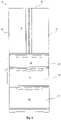
- FIG 1 is a front view showing the appearance of a refrigerator 10 according to the present embodiment.
- the refrigerator 10 comprises a heat-insulating cabinet 11 as a main body, and storage compartments for storing foods and the like are formed in the heat-insulating cabinet 11.
- the uppermost layer is the refrigerating compartment 15
- an upper freezing compartment 18 is below the refrigerating compartment 15
- a lower freezing compartment 19 is below the upper freezing compartment 18, and the lowermost layer is a vegetable compartment 20.
- the upper freezing compartment 18 and the lower freezing compartment 19 are both storage compartments within a freezing temperature range, and they may be collectively referred to as a freezing compartment 17 in the following depictions.
- the upper freezing compartment 18 may be partitioned in a left-right direction, and one side may be used as an ice making compartment.
- the front of the heat-insulating cabinet 11 comprises an opening, the openings corresponding to the abovementioned storage compartments are each provided with a heat-insulating door 21, and these heat-insulating doors may be opened and closed freely.
- the refrigerating compartment 15 is divided in the left-right direction and the left and right parts are closed by respective heat-insulating doors 21.
- Upper and lower ends of the heat-insulating doors 21 on outer sides in a widthwise direction are rotatably mounted on the heat-insulating cabinet 11.
- the heat-insulating doors 23, 24 and 25 are integrally assembled with respective storage containers, may be drawn freely along the front of the refrigerator 10, and be supported by the heat-insulating cabinet 11. Specifically, the heat-insulating door 23 closes the upper freezing compartment 18, the heat-insulating door 24 closes the lower freezing compartment 19, and the heat-insulating door 25 closes the vegetable compartment 20.
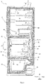
- FIG 2 is a side cross-sectional view showing the schematic structure of the refrigerator 10.
- the heat-insulating cabinet 11 as the main body of the refrigerator 10 comprises a housing 12 made of a steel plate with an opening in the front, and a liner 13 made of a synthetic resin, disposed within the housing 12 with a gap between the liner 13 and the housing 12 and having an opening in the front.
- the gap between the housing 12 and the liner 13 is filled with a heat-insulating material 14 made of foamed polyurethane.
- each of the above-mentioned heat-insulating doors 21 employs the same heat-insulating structure as the heat-insulating cabinet 11.
- the refrigerating compartment 15 and the freezing compartment 17 located at the layer therebelow are partitioned by a heat-insulating partition wall 42.
- the upper freezing compartment 18 and the lower freezing compartment 19 disposed at the layer therebelow communicate with each other, and the cooled air, namely, the cold air may circulate freely.
- the freezing compartment 17 and the vegetable compartment 20 are partitioned by a heat-insulating partition wall 43.
- the rear of the refrigerating compartment 15 is partitioned by a partition 65 made of a synthetic resin to form a refrigerating compartment cold air supply passage 29 for supplying cold air to the refrigerating compartment 15.
- a partition 65 made of a synthetic resin to form a refrigerating compartment cold air supply passage 29 for supplying cold air to the refrigerating compartment 15.
- air outlets 33 through which cold air flows into the refrigerating compartment 15 are formed.
- a freezing compartment cold air supply passage 31 is formed on an inner side of the refrigerating compartment 17, and cold air cooled by a cooler 45 flows through the freezing compartment cold air supply passage 31 into the freezing compartment 17.
- a cooling chamber 26 is formed on an inner side behind the freezing compartment cold air supply path 31.
- a cooler 45 is disposed in the cooling chamber and is an evaporator for cooling air circulating in the refrigerator.
- the freezing compartment cold air supply passage 31 is a space surrounded by a front cover 67 in the front and a partition 66 in the rear.
- the cooler 45 is connected to a compressor 44, a heat radiator (not shown), and a capillary tube (not shown) as an expansion means via a refrigerant pipe, and is a member constituting a vapor compression type refrigeration cycle circuit.
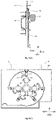
- FIG 3 is a side cross-sectional view showing a structure nearby the cooling chamber 26 of the refrigerator 10.
- the cooling chamber 26 is disposed in an interior of the heat-insulating cabinet 11 and inside the freezing compartment cold air supply passage 31.
- the cooling chamber 26 and the freezing compartment 17 are partitioned by the partition 66 made of a synthetic resin.
- the freezing compartment cold air supply passage 31 formed in the front of the cooling chamber 26 is a space formed between the cooling chamber 26 and the front cover 67 made of the synthetic resin and assembled in the front of the freezing compartment cold air supply passage 31, and is a passage through which the cold air cooled by the cooler 45 flows into the freezing compartment 17.
- the front cover 67 is formed with air outlets 34 which are openings through which cold air is blown into the refrigerating compartment 17.
- An air return vent 38 for returning air from the freezing compartment 17 to the cooling chamber 26 is formed on a back side of a lower portion of the lower freezing compartment 19. Furthermore, an air return vent 28 is formed below the cooling chamber 26 and communicated with the air return vent 38, and sucks return cold air from respective storage compartments into the cooling chamber 26. The cold air returning through an air return vent 39 ( FIG. 2 ) of the vegetable compartment 20 and a vegetable compartment cold air return passage 37 also flows into the air return vent 28.
- a defrosting heater 46 is disposed below the cooler 45 to melt the frost attached to the cooler 45.
- the defrosting heater 46 is a resistive heater.
- An air blowing vent 27 is formed in an upper portion of the cooling chamber 26 and is an opening connected to the respective storage compartments.
- the air blowing vent 27 is an opening into which the cold air cooled by the cooler 45 flows, and enables the cooling chamber 26, the refrigerating compartment cold air supply passage 29 and the freezing compartment cold air supply passage 31 to be communicated with one another.
- the air blowing vent 27 is provided with a blower 47 that blows cold air to the freezing compartment 17 and the like from the front.
- a function of a damper is assumed by a rotatable shielding wall 71 of a shielding device 70 described later, so the damper may be omitted.
- a shielding device 70 is disposed outside the air blowing vent 27 of the cooling chamber 26, to properly close the air passage connected to the air blowing vent 27.
- the shielding device 70 is covered by the front cover 67 from the front.
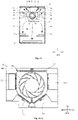
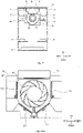
- FIG 4 illustrates a configuration in which the shielding device 70 for limiting the air passage is assembled.
- FIG 4(A) is a perspective view of the partition 66 with the shielding device 70 being assembled
- FIG 4(B) is a cross-sectional view taken along line A-A of FIG 4(A)
- FIG 4(C) is a view of the construction of the air passage when the front cover 67 is viewed from the rear.
- the air blowing vent 27 penetrating in a thickness direction is formed in an upper portion of the partition 66, and the blower 47 and the shielding device 70 are disposed in front of the air blowing vent 27.
- the shielding device 70 is hidden by the partition 66.
- an opening section 59 formed on an upper end side of the partition 66 is communicated with the refrigerating compartment cold air supply passage 29 shown in FIG 3 .
- the freezing compartment cold air supply passage 31 is formed in a space surrounded by the partition 66 and the front cover 67. As described later, the freezing compartment cold air supply passage 31 is divided into a plurality of air passages.
- the shielding device 70 and a shielding wall driving mechanism 60 are disposed between the partition 66 and the front cover 67. The shielding device 70 shields the blower 47, and the shielding wall driving mechanism 60 drives the shielding device 70. The configuration of the shielding device 70 and the shielding wall driving mechanism 60 will be described below with reference to FIG 5 .
- a plurality of air passages are formed by partitioning an internal space of the front cover 67. Specifically, rib-shaped air passage partition walls 50 and 56 extending rearward from a rear main surface of the front cover 67 are formed. The rear ends of the air passage partition walls 50 and 56 abut against the partition 66 shown in FIG. 4(B) .
- the air passage through which the cold air is blown and supplied is divided into a refrigerating compartment cold air supply passage 51, an upper refrigerating compartment cold air supply passage 52, and a lower refrigerating compartment cold air supply passage 53 in turn from top.
- the cold air blown to the refrigerating compartment 15 circulates in the refrigerating compartment cold air supply passage 51
- the cold air blown to the upper freezing compartment 18 circulates in the upper freezing compartment cold air supply passage 51
- the cold air blown to the lower freezing compartment 19 circulates in the lower freezing compartment cold air supply passage 53.
- the cold air flowing through the refrigerating compartment cold air supply passage 51 is blown through the opening section 59 to the refrigerating compartment 15 shown in FIG. 2 .
- the cold air flowing through the upper freezing compartment cold air supply passage 52 is blown through the air outlet 34 to the upper freezing compartment 18 shown in FIG. 2 .
- the cold air flowing through the lower freezing compartment cold air supply passage 53 is blown through the air outlet 34 to the lower freezing compartment 19 shown in FIG. 2 .
- the refrigerating compartment cold air supply passage 51, the upper freezing compartment cold air supply passage 52 and the lower freezing compartment cold air supply passage 53 spread around with the shielding device 70 as a center.
- the refrigerating compartment cold air supply passage 51 and the upper freezing compartment cold air supply passage 52 are partitioned by an air passage partitioning wall 50. Then, the upper freezing compartment cold air supply passage 52 and the lower freezing compartment cold air supply passage 53 are partitioned by an air passage partitioning wall 56.
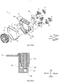
- FIG. 5(A) is an exploded perspective view showing the shielding device 70
- FIG. 5(B) is a side cross-sectional view showing the shielding device 70.
- the shielding device 70 comprises a support base 63, a rotatable shielding wall 71 and a shielding wall driving mechanism 60.
- the shielding device 70 is a device that shields the air passages of the cold air blown by the blower 47.
- the air passages connecting the cooling chamber 26 with respective storage compartments are made communicated by making the shielding device 70 in an open state, and, the air passages are cut off by making the shielding device 70 in a closed state.
- the blower 47 is disposed at a center of the support base 63 by fastening with screws.
- the blower 47 has for example a centrifugal fan such as a turbo fan, and a blowing motor that rotates the centrifugal fan, and blows cold air outward in a radial direction.
- the support base 63 is an integrally-formed member made of a synthetic resin.
- the rotatable shielding walls 71 are rotatably disposed on a rear side of the support base 63.
- Side wall portions 58 are formed in a peripheral portion of the support base 63.
- the side wall portions 58 are portions extending rearward from the support base 63.
- a plurality of side wall portions 58 are disposed at substantially equal intervals in a circumferential direction of the support base 63.
- the side wall portions 58 are disposed between the rotatable shielding walls 71.
- the rear ends of the side walls 58 are fastened to a partition 66 shown in FIG. 4(B) in a fastening manner such as screws.
- the rotatable shielding walls 71 each are a rectangular plate-shaped member formed of a synthetic resin, and have long sides along a line tangential to the outer side of the blower 47.
- the rotatable shielding walls 71 are mounted adjacent to the edges of the support base 63 and rotatable about an axis parallel to a plane of the support base 63.
- a plurality of rotatable shielding walls 71 (five in the present embodiment) are disposed.
- the rotatable shielding walls 71 are disposed on paths through which the cold air blown by the blower 47 circulates, and shield respective air passages.
- the shielding wall driving mechanism 60 comprises a cam 61, a rotary disk 73, and a drive motor 74 that rotates the rotary disk 73.
- each rotatable shielding wall 71 comprises a shielding wall driving mechanism 60. That is, five shielding wall driving mechanisms 60 are provided for the five rotatable shielding walls 71.
- the respective shielding wall driving mechanisms 60 rotate the rotatable shielding walls 71 according to an instruction from a control device not shown, so that diversity of the rotation types of the rotatable shielding walls 71 can be achieved without restriction.
- the specific shapes and functions of the shielding wall driving mechanisms 60 will be described later.
- FIG. 6 illustrates the shielding wall driving mechanism 60 for driving the rotatable shielding walls 71.
- FIG. 6(A) is an exploded perspective view showing the shielding wall driving mechanism 60
- FIG. 6(B) is a perspective view of a cam 61.
- the shielding wall driving mechanism 60 comprises a cam 61, a rotary disk 73 that engages with a moving shaft 76 of the cam 61, and a drive motor 74 for rotating the rotary disk 73.
- the cam 61 is a flat rectangular parallelepiped member formed of a synthetic resin. As shown in FIG. 6(B) , a right end of the cam 61 is formed with a rotatable connection portion 48 in which is formed a hole portion through which a pin 55 can run. The cam 61 is received in a cam-receiving portion in a slidable state, the cam-receiving portion being formed by recessing a front surface of the support base 63 shown in FIG 5(A) .
- the rotary disk 73 is a substantially tongue-shaped plate-shaped member, with a left end portion being connected to a rotation shaft of the drive motor 74 in a way that the left end portion is non-rotatable relative to the rotation shaft. Therefore, the rotary disk 73 rotates driven by the drive motor 74.
- a moving shaft sliding slot 80 for rotating the moving shaft 76 of the cam 61.
- the moving shaft sliding slot 80 is in an arcuate curved shape, and the moving shaft sliding slot 80 is slidably fitted with the moving shaft 76 of the cam 61.
- the rotatable shielding wall 71 is formed with a rotatable connection portion 68 which protrudes obliquely from a base end of the rotatable shielding wall 71.
- the rotatable connection portion 68 is formed with a hole portion through which a pin 55 can run.
- Rotational connection portions 64 are formed adjacent to both ends of a lateral side of the rotatable shielding wall 71.
- the rotatable connection portions 64 each are formed with a hole through which a pin 69 can run.
- the moving shaft 76 is a cylindrical protrusion protruding from the front of the cam 61.
- a diameter of the moving shaft 76 is slightly shorter than a width of the moving shaft sliding slot 80 formed in the rotary disk 73.
- the moving shaft 76 slidably engages with the moving shaft sliding slot 80.
- the pin 55 runs through the hole portion of the rotatable connection portion 48 of the cam 61 and the hole portion of the rotatable connection portion 68 of the rotatable shielding wall 71, and the cam 61 is connected with the rotatable shielding wall 71 and rotatable about the pin 55.
- the rotatable shielding wall 71 is rotatably connected with the support base 63 shown in FIG. 5(A) via the pin 69 which runs through the rotatable connection portions 64 of the rotatable shielding wall 71.
- the moving shaft sliding slot 80 can be rotated by the drive motor 74, thereby performing the opening and closing operations of the rotatable shielding wall 71.
- the drive motor 74 rotates the rotary disk 73
- the moving shaft 76 moves in a left-right direction along the moving shaft sliding slot 80, i.e., the cam 61 moves in the left-right direction.
- the rotatable shielding wall 71 rotatably connected with the cam 61 rotates with the rotatable connection portion 64 as a rotation center, thereby performing the opening and closing operations of the rotatable shielding wall 71.
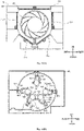
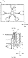
- FIG. 7 is a view showing the shielding device 70 according to the embodiment of the present invention, wherein FIG. 7(A) is a view of rotatable shielding walls of the shielding device 70 as viewed from the rear, and FIG. 7(B) is a view showing the configuration of rotary disks as viewed from front.
- the shielding device 70 comprises rotatable shielding walls 711, 712, 713, 714, and 715 as the above-mentioned rotatable shielding walls 71.
- the rotatable shielding walls 711-715 have a rectangular shape having long sides substantially parallel to a line tangential to the outside of the blower 47 shown in FIG. 5(A) .
- the rotatable shielding walls 711-715 are rotatably mounted on the peripheral portion of the support base 63 shown in FIG. 5(A) .
- a radially inner end of the rotatable shielding wall 711 is rotatably connected to a cam 611 on which a moving shaft 761 is formed.
- a radially inner end of the rotatable shielding wall 712 is rotatably connected to a cam 612 on which a moving shaft 762 is formed.
- a radially inner end of the rotatable shielding wall 711 is rotatably connected to a cam 613 on which a moving shaft 763 is formed.
- a radially inner end of the rotatable shielding wall 714 is rotatably connected to a cam 614 on which a moving shaft 764 is formed.
- a radially inner end of the rotatable shielding wall 715 is rotatably connected to a cam 615 on which a moving shaft 765 is formed
- the cams 611-615 are respectively rotatably connected to inside edges of the rotatable shielding walls 711-715. In this way, when the cams 611 to 615 are arranged outside, the rotatable shielding walls 711-715 are in an upstanding state. On the other hand, when the cams 612 to 615 are arranged inside, and the rotatable shielding walls 712-715 are in a horizontally-lying state.
- the moving shaft sliding slot 801 of the rotary disk 731 slidably engages with the moving shaft 761 of the cam 611.
- the moving shaft sliding slot 802 of the rotary disk 732 slidably engages with the moving shaft 762 of the cam 612.
- the moving shaft sliding slot 803 of the rotary disk 733 slidably engages with the moving shaft 763 of the cam 613.
- the moving shaft sliding slot 804 of the rotary disk 734 slidably engages with the moving shaft 764 of the cam 614.
- the moving shaft sliding slot 805 of the rotary disk 735 slidably engages with the moving shaft 765 of the cam 615.
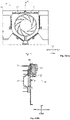
- FIG. 8 shows the configuration of the shielding device 70 in a fully-closed state.
- FIG. 8(A) is a view of the shielding device 70 in the fully-closed state as viewed from the rear
- FIG. 8(B) is a cross-sectional view taken along a section line B-B of FIG. 8(A)
- FIG. 8(C) is a view of rotary disks 73 in the fully-closed state as viewed from the front
- FIG. 8(D) is an enlarged view of main points of FIG. 8(B) .
- the fully-closed state refers to a state in which the surrounding of the blower 47 is shielded by the rotatable shielding walls 71 to thereby close the air blowing vent 27 shown in FIG. 4 .
- the blower 47 does not rotate.
- the shielding device 70 prevents air from flowing out from the blower 47 to the outside in the fully-closed state. That is, in the fully-closed state, all the rotatable shielding walls 71 are in the upstanding state, and the communication with the air passages for supplying cold air is cut off so that cold air is not supplied to the refrigerating compartment 15 and the freezing compartment 17. In addition, during the defrosting process of defrosting the cooler 45 shown in FIG. 2 , the shielding device 70 is also in the fully-closed state so that ward air does not flow from the cooling chamber 26 into the refrigerating compartment 15 and the freezing compartment 17.
- the rotatable shielding wall 71 in the fully-closed state, is in a closed state in which the rotatable shielding wall 71 stands substantially perpendicular to the main surface of the support base 63.
- all the rotatable shielding walls 71 of the shielding device 70 are in a closed state.
- the rear end of the rotatable shielding wall 71 abuts against the partition 66 shown in FIG. 4 or is arranged close to the partition 66.
- the drive motor 74 is turned on to rotate the rotary disk 73.
- the rotary disk 73 rotates counterclockwise to cause the moving shaft 76 to slide in the moving shaft sliding slot 80, so that the moving shaft 76 is disposed at the outside end of the moving shaft sliding slot 80.
- the cam 61 moves radially outward.
- the rotatable shielding wall 71 rotatably connected with the cam 61 rotates with the vicinity of the rotatable connection portion 68 as a rotation center, and is in a closed state in which the rotatable shielding wall 71 stands up substantially at a right angle to the main surface of the support base 63.
- FIG. 9 shows the configuration of the shielding device 70 in a fully-open state.
- FIG. 9(A) is a view showing the shielding device 70 in the fully-open state as viewed from the rear
- FIG. 9(B) is a cross-sectional view of the shielding device taken along a section line C-C of FIG. 9(A)
- FIG. 9(C) is a view showing rotary disks 73 in the fully-open state as viewed from the front
- FIG. 9(D) is an enlarged view of main points of FIG. 9(B) .
- the fully-open state refers to a state in which the communication between the blower 47 and the air passages for supplying cold air is not shielded by the rotatable shielding walls 71, so that the cold air blown by the blower 47 diffuses around.
- the shielding device 70 in the fully-open state, does not hinder air from flowing from the blower 47 to the outside. That is, in the fully-open state, the cold air blown from the blower 47 to the shielding device 70 is blown to the refrigerating compartment 15 and the freezing compartment 17 without being interfered by the rotatable shielding wall 71. As shown in FIG. 9(A) , in the fully-open state, all the rotatable shielding walls 71 tilt outward in the radial direction and get into a horizontally-lying state.
- all the rotatable shielding walls 71 are in the horizontally-lying state in which they are substantially parallel to the main surface of the support base 63. Since all the rotatable shielding walls 71 of the shielding device 70 are in the open state, there are no rotatable shielding walls 71 in the air passages through which the blower 47 blows cold air, so that the flow resistance of the air passages can be reduced and the amount of the cold air supplied by the blower 47 can be increased.
- the rotatable shielding wall 71 rotatably connected with the end of the cam 61 rotates and tilts with the vicinity of the rotatable connection portion 68 as a rotation center, and gets into a state in which the main surface of the rotatable shielding wall 71 is substantially parallel to the main surface of the support base 63.
- FIG. 10 through FIG. 23 illustrate a method of switching air passages using the shielding device 70 with the above configuration.
- FIG. 10 shows a state in which the cold air is supplied to the lower freezing compartment 19 only
- FIG. 10(A) is a view of the shielding device 70 as viewed from the rear
- FIG. 10(B) is a view of rotary disks such as the rotary disk 731 as viewed from the front
- FIG. 11 is a view showing conditions of the air passage when cold air is supplied to the lower freezing compartment 19 only, as viewed from the rear
- FIG. 12 shows a situation when cold air is supplied to the freezing compartment 17 only
- FIG. 12(A) is a view of the shielding device 70 as viewed from the rear
- FIG. 12(B) is a view of rotary disks such as the rotary disk 731 as viewed from the front.
- FIG. 12 shows a situation when cold air is supplied to the freezing compartment 17 only
- FIG. 12(A) is a view of the shielding device 70 as viewed from the rear
- FIG. 12(B) is a view of rotary disks such as the rotary disk 7
- FIG. 13 is a view of a state of the air passage when cold air is supplied to the freezing compartment 17 only, as viewed from the rear.
- FIG. 14 shows a state in which the cold air is supplied to the upper freezing compartment 18 only
- FIG. 14(A) is a view of the shielding device 70 as viewed from the rear
- FIG. 14(B) is a view of rotary disks such as the rotary disk 731 as viewed from the front.
- FIG. 15 is a view of conditions of the air passage when cold air is supplied to the upper freezing compartment 18 only as viewed from the rear.
- FIG. 16 shows a state when cold air is not supplied
- FIG. 16(A) is a view of the shielding device 70 as viewed from the rear
- FIG. 16(B) is a view of rotary disks such as the rotary disk 731 as viewed from the front.
- FIG. 17 is a view of a state of air passages when cold air is not supplied, as viewed from the rear.
- FIG. 18 shows a state when cold air is supplied to the refrigerating compartment 15 only.
- FIG. 18(A) is a view of the shielding device 70 as viewed from the rear
- FIG. 18(B) is a view of rotary disks such as the rotary disk 731 as viewed from the front.
- FIG. 19 is a view of a state of the air passage when cold air is supplied to the refrigerating compartment 15 only, as viewed from the rear.
- FIG. 20 shows a state when cold air is supplied to the upper freezing compartment 18 and the refrigerating compartment 15
- FIG. 20(A) is a view of the shielding device 70 as viewed from the rear
- FIG. 20(B) is a view of rotary disks such as the rotary disk 731 as viewed from the front.
- FIG. 21 is a view of conditions of air passages when cold air is supplied to the upper freezing compartment 18 and the refrigerating compartment 15 as viewed from the rear.
- FIG. 22 shows a state when cold air is supplied to the entire freezing compartment 17 and the refrigerating compartment 15.
- FIG. 22(A) is a view of the shielding device 70 as viewed from the rear
- FIG. 22(B) is a view of rotary disks such as the rotary disk 731 as viewed from the front.
- FIG. 23 is a view of conditions of air passages when cold air is supplied to the entire freezing compartment 17 and the refrigerating compartment 15 as viewed from the rear.
- the clockwise direction when the shielding device 70 is viewed from the rear is sometimes referred to as a "forward direction”
- the counterclockwise direction when the shielding device 70 is viewed from the rear is sometimes referred to as a "reverse direction”.
- a radial direction and a circumferential direction of the blower 47 are briefly referred to as a radial direction and a circumferential direction.
- FIG. 10 and FIG. 11 show a state in which cold air is supplied to the lower freezing compartment 19.
- FIG. 10(A) is a view of the shielding device 70 in this state as viewed from the rear
- FIG. 10(B) is a view of rotary disks such as the rotary disk 731 in this state as viewed from the front
- FIG. 11 is a view of conditions of air passages in this state as viewed from rear.
- the rotatable shielding wall 711, the rotatable shielding wall 712 and the rotatable shielding wall 715 are in the closed state, and the rotatable shielding wall 713 and the rotatable shielding wall 714 are in the open state.
- the closed state and the open state being set, cold air can be blown by the blower 47 to the lower freezing compartment 19 only.
- a drive motor 741 rotates a rotary disk 731 in the reverse direction, and a moving shaft 761 is arranged at a radially outer end of a moving shaft sliding slot 801 of the rotary disk 731.
- a rotary disk 732 is rotated in the reverse direction by a drive motor 742.
- a moving shaft 762 is arranged at a radially outer end of a moving shaft sliding slot 802 of the rotary disk 732.
- a drive motor 743 rotates a rotary disk 733 in the forward direction, and a moving shaft 763 is arranged at a radially inner end of a moving shaft sliding slot 803 of the rotary disk 733.
- a drive motor 744 rotates a rotary disk 734 in the forward direction, and a moving shaft 764 is arranged at a radially inner end of a moving shaft sliding slot 804 of the rotary disk 734.
- a drive motor 745 rotates a rotary disk 735 in the reverse direction, and a moving shaft 765 is arranged at a radially outer end of a moving shaft sliding slot 805 of the rotary disk 735.
- the rotatable shielding wall 711 With the cam 611 together with the moving shaft 761 being arranged radially outside, the rotatable shielding wall 711 is in a closed state. With the cam 612 together with the moving shaft 762 being arranged radially outside, the rotatable shielding wall 712 is in a closed state. With the cam 613 together with the moving shaft 763 being arranged radially inside, the rotatable shielding wall 713 is in an open state. With the cam 614 together with the moving shaft 764 being arranged radially inside, the rotatable shielding wall 714 is in an open state. With the cam 615 together with the moving shaft 765 being arranged radially outside, the rotatable shielding wall 715 is in a closed state.
- the rotatable shielding walls 713, 714 are in the open state, so cold air is blown from the lower freezing compartment cold air supply passage 53.
- the cold air that has flowed into the lower freezing compartment cold air supply passage 53 is blown out through an air outlet 34 to the lower freezing compartment 19 shown in FIG. 2 .
- the rotatable shielding walls 711, 712 and 715 are in the closed state, cold air is not blown to the refrigerating compartment 15 and the upper freezing compartment 18 shown in FIG. 2 .
- FIG. 12 and FIG. 13 each show a state in which cold air is supplied to the freezing compartment 17 only.
- FIG. 12(A) is a view of the shielding device 70 in this state as viewed from the rear
- FIG. 12(B) is a view of rotary disks such as the rotary disk 731 in this state as seen from the front
- FIG. 13 is a view of conditions of the air passage in this state as viewed from rear.
- the rotatable shielding wall 711 is in the closed state, and the rotatable shielding walls 712, 713, 714 and 715 are in the open state.
- the open state and closed state being set, cold air can be blown by the blower 47 to the freezing compartment 17 shown in FIG. 2 .
- the drive motor 741 rotates the rotary disk 731 in the reverse direction, and the moving shaft 761 is arranged at a radially outer end of the moving shaft sliding slot 801 of the rotary disk 731.
- the drive motor 742 rotates the rotary disk 732 in the forward direction, and the moving shaft 762 is arranged at a radially inner end of the moving shaft sliding slot 802 of the rotary disk 732.
- the drive motor 743 rotates the rotary disk 733 in the forward direction, and the moving shaft 763 is arranged at a radially inner end of the moving shaft sliding slot 803 of the rotary disk 733.
- the drive motor 744 rotates the rotary disk 734 in the forward direction, and the moving shaft 764 is arranged at a radially inner end of the moving shaft sliding slot 804 of the rotary disk 734.
- the drive motor 745 rotates the rotary disk 735 in the forward direction, and the moving shaft 765 is arranged at a radially inner end of the moving shaft sliding slot 805 of the rotary disk 735.
- the rotatable shielding wall 711 With the cam 611 together with the moving shaft 761 being arranged radially outside, the rotatable shielding wall 711 is in the closed state. With the cam 612 together with the moving shaft 762 being arranged radially outside, the rotatable shielding wall 712 is in the open state. With the cam 613 together with the moving shaft 763 being arranged radially inside, the rotatable shielding wall 713 is in the open state. With the cam 614 together with the moving shaft 764 being arranged radially inside, the rotatable shielding wall 714 is in the open state. With the cam 615 together with the moving shaft 765 being arranged radially inside, the rotatable shielding wall 715 is in the open state.
- the rotatable shielding walls 712, 715 are in the open state, so cold air is blown to the upper freezing compartment cold air supply passage 52, and blown to the upper freezing compartment 18 shown in FIG. 2 through the air outlet 34.
- the rotatable shielding walls 713, 714 are in the open state, cold air is blown to the lower freezing compartment cold air supply passage 53, and blown to the lower freezing compartment 19 shown in FIG. 2 via the air outlet 34.
- the rotatable shielding wall 711 being in the closed state, cold air is not blown to the refrigerating compartment 15.
- FIG 14 and FIG. 15 show a state in which the cold air is supplied to the upper freezing compartment 18 only.
- FIG. 14(A) is a view of the shielding device 70 in this state as viewed from the rear
- FIG. 14(B) is a view of rotary disks such as the rotary disk 731 in this state as viewed from the front
- FIG. 15 is a view of conditions of air passages in this state as viewed from the rear.
- the rotatable shielding walls 711, 713, and 714 are in the closed state, and the rotatable shielding walls 712, 715 are in the open state.
- the open state and the closed state being set, cold air is blown to the upper freezing compartment 18 only by the blower 47.
- the drive motor 741 rotates the rotary disk 731 in the reverse direction, and the moving shaft 761 is arranged at a radially outer end of the moving shaft sliding slot 801 of the rotary disk 731.
- the drive motor 742 rotates the rotary disk 732 in the forward direction.
- the moving shaft 762 is arranged at a radially inner end of the moving shaft sliding slot 802 of the rotary disk 732.
- the drive motor 743 rotates the rotary disk 733 in the reverse direction, and the moving shaft 763 is arranged at a radially outer end of the moving shaft sliding slot 803 of the rotary disk 733.
- the drive motor 744 rotates the rotary disk 734 in the reverse direction, and the moving shaft 764 is arranged at a radially outer end of the moving shaft sliding slot 804 of the rotary disk 734.
- the drive motor 745 rotates the rotary disk 735 in the forward direction, and the moving shaft 765 is arranged at a radially inner end of the moving shaft sliding slot 805 of the rotary disk 735.
- the rotatable shielding wall 711 With the cam 611 together with the moving shaft 761 being arranged radially outside, the rotatable shielding wall 711 is in the closed state. With the cam 612 together with the moving shaft 762 being arranged radially inside, the rotatable shielding wall 712 is in the open state. With the cam 613 together with the moving shaft 763 being arranged radially outside, the rotatable shielding wall 713 is in the closed state. With the cam 614 together with the moving shaft 764 being arranged radially outside, the rotatable shielding wall 714 is in the closed state. With the cam 615 together with the moving shaft 765 being arranged radially inside, the rotatable shielding wall 715 is in the open state.
- the rotatable shielding wall 711 is in the closed state, so cold air is not blown to the refrigerating compartment 15.
- the rotatable shielding walls 713 and 714 are also in the closed state, so cold air is not blown to the lower freezing compartment 19.
- FIG. 16 and FIG. 17 show the fully-closed state in which the shielding device 70 closes all the air passages.
- FIG. 16(A) is a view of the shielding device 70 in this state as viewed from the rear
- FIG. 16(B) is a view of rotary disks such as the rotary disk 731 in this state as viewed from the front
- FIG. 17 is a view of conditions of air passages in this state as viewed from the rear.
- the rotatable shielding walls 711-715 are in the closed state. In this state, air can be prevented from flowing into respective air passages.
- the drive motor 741 rotates the rotary disk 731 in the reverse direction, and the moving shaft 761 is arranged at a radially outer end of the moving shaft sliding slot 801 of the rotary disk 731.
- the drive motor 742 rotates the rotary disk 732 in the reverse direction, and the moving shaft 762 is arranged at a radially outer end of the moving shaft sliding slot 802 of the rotary disk 732.
- the drive motor 743 rotates the rotary disk 733 in the reverse direction, and the moving shaft 763 is arranged at a radially outer end of the moving shaft sliding slot 803 of the rotary disk 733.
- the drive motor 744 rotates the rotary disk 734 in the reverse direction, and the moving shaft 764 is arranged at a radially outer end of the moving shaft sliding slot 804 of the rotary disk 734.
- the drive motor 745 rotates the rotary disk 735 in the reverse direction, and the moving shaft 765 is arranged at a reverse direction end of the moving shaft sliding slot 805 of the rotary disk 735.
- the rotatable shielding wall 711 With the cam 611 together with the moving shaft 761 being arranged radially outside, the rotatable shielding wall 711 is in the closed state. With the cam 612 together with the moving shaft 762 being arranged radially outside, the rotatable shielding wall 712 is in the closed state. With the cam 613 together with the moving shaft 763 being arranged radially outside, the rotatable shielding wall 713 is in the closed state. With the cam 614 together with the moving shaft 764 being arranged radially outside, the rotatable shielding wall 714 is in the closed state. With the cam 615 together with the moving shaft 765 being arranged radially outside, the rotatable shielding wall 715 is in the closed state.
- the rotatable shielding walls 711-715 are in the closed state, and cold air is not supplied to all the storage compartments.
- the cooling chamber 26 and the air passages can be shielded by the rotatable shielding wall 71. Therefore, when the interior of the cooling chamber 26 is heated during the defrosting process, the warm air in the interior of the cooling chamber 26 can be prevented from leaking to the respective storage compartments via the respective air passages.
- FIG. 18 and FIG. 19 show a state in which cold air is supplied to the refrigerating compartment 15 only.
- FIG. 18(A) is a view of the shielding device 70 in this state as viewed from the rear
- FIG. 18(B) is a view of rotary disks such as the rotary disk 731 in this state as viewed from the front
- FIG. 19 is a view of conditions of air passages in this state as viewed from the rear.
- the rotatable shielding wall 711 is in the open state, and the rotatable shielding walls 712-715 are in the closed state.
- the open state and the closed state being set, cold air can be blown by the blower 47 to the refrigerating compartment 15 only, as described later.
- the drive motor 741 rotates the rotary disk 731 in the forward direction, and the moving shaft 761 is arranged at a radially inner end of the moving shaft sliding slot 801 of the rotary disk 731.
- the drive motor 742 rotates the rotary disk 732 in the reverse direction, and the moving shaft 762 is arranged at a radially outer end of the moving shaft sliding slot 802 of the rotary disk 732.
- the drive motor 743 rotates the rotary disk 733 in the reverse direction, and the moving shaft 763 is arranged at a radially outer end of the moving shaft sliding slot 803 of the rotary disk 733.
- the drive motor 744 rotates the rotary disk 734 in the reverse direction, and the moving shaft 764 is arranged at a radially outer end of the moving shaft sliding slot 804 of the rotary disk 734.
- the drive motor 745 rotates the rotary disk 735 in the reverse direction, and the moving shaft 765 is arranged at a radially outer end of the moving shaft sliding slot 805 of the rotary disk 735.
- the rotatable shielding wall 711 With the cam 611 together with the moving shaft 761 being arranged radially inside, the rotatable shielding wall 711 is in the open state. With the cam 612 together with the moving shaft 762 being arranged radially outside, the rotatable shielding wall 712 is in the closed state. With the cam 613 together with the moving shaft 763 being arranged radially outside, the rotatable shielding wall 713 is in the closed state. With the cam 614 together with the moving shaft 764 being arranged radially outside, the rotatable shielding wall 714 is in the closed state. With the cam 615 together with the moving shaft 765 being arranged radially outside, the rotatable shielding wall 715 is in the closed state.
- FIG. 20 and FIG. 21 show a state in which the shielding device 70 supplies cold air to the refrigerating compartment 15 and the upper freezing compartment 18.
- FIG. 20(A) is a view of the shielding device 70 in this state as viewed from the rear
- FIG. 20(B) is a view of rotary disks such as the rotary disk 731 in this state as viewed from the front
- FIG. 21 is a view of conditions of air passages in this state as viewed from the rear.
- the rotatable shielding walls 711, 712 and 715 are in the open state, and the rotatable shielding walls 713, 714 are in the closed state.
- the open state and the closed state being set, cold air can be blown by the blower 47 to the refrigerating compartment 15 and the upper freezing compartment 18.
- the drive motor 741 rotates the rotary disk 731 in the forward direction, and the moving shaft 761 is arranged at a radially inner end of the moving shaft sliding slot 801 of the rotary disk 731.
- the drive motor 742 rotates the rotary disk 732 in the forward direction, and the moving shaft 762 is arranged at a radially inner end of the moving shaft sliding slot 802 of the rotary disk 732.
- the drive motor 743 rotates the rotary disk 733 in the reverse direction, and the moving shaft 763 is arranged at a radially outer end of the moving shaft sliding slot 803 of the rotary disk 733.
- the drive motor 744 rotates the rotary disk 734 in the reverse direction, and the moving shaft 764 is arranged at a radially outer end of the moving shaft sliding slot 804 of the rotary disk 734.
- the drive motor 745 rotates the rotary disk 735 in the forward direction, and the moving shaft 765 is arranged at a radially inner end of the moving shaft sliding slot 805 of the rotary disk 735.
- the rotatable shielding wall 711 With the cam 611 together with the moving shaft 761 being arranged radially inside, the rotatable shielding wall 711 is in the open state. With the cam 612 together with the moving shaft 762 being arranged radially inside, the rotatable shielding wall 712 is in the open state. With the cam 613 together with the moving shaft 763 being arranged radially outside, the rotatable shielding wall 713 is in the closed state. With the cam 614 together with the moving shaft 764 being arranged radially outside, the rotatable shielding wall 714 is in the closed state. With the cam 615 together with the moving shaft 765 being arranged radially inside, the rotatable shielding wall 715 is in the open state.
- the rotatable shielding wall 711 is in the open state, and cold air is blown to the refrigerating compartment 15 via the refrigerating compartment cold air supply passage 29.
- the rotatable shielding walls 712, 715 being in the open state, the cold air is blown to the upper freezing compartment cold air supply passage 52 and blown out via the air outlet 34 to the upper freezing compartment 18.
- the rotatable shielding walls 713-714 are in the closed state, so cold air is not blown to the lower freezing compartment 19.
- FIG 22 and FIG. 23 show a fully-open state in which cold air is supplied to both the refrigerating compartment 15 and the freezing compartment 17.
- FIG 22(A) is a view of the shielding device 70 in this state as viewed from the rear
- FIG 22(B) is a view of rotary disks such as the rotary disk 731 in this state as viewed from the front
- FIG. 23 is a view of conditions of air passages in this state as viewed from the rear.
- the rotatable shielding walls 711, 712, 713, 714 and 715 are in the open state. With the fully-open state being set, cold air can be blown by the blower 47 to the refrigerating compartment 15 and the freezing compartment 17 as described later.
- the drive motor 741 rotates the rotary disk 731 in the forward direction, and the moving shaft 761 is arranged at a radially inner end of the moving shaft sliding slot 801 of the rotary disk 731.
- the drive motor 742 rotates the rotary disk 732 in the forward direction, and the moving shaft 762 is arranged at a radially inner end of the moving shaft sliding slot 802 of the rotary disk 732.
- the drive motor 743 rotates the rotary disk 733 in the forward direction, and the moving shaft 763 is arranged at a radially inner end of the moving shaft sliding slot 803 of the rotary disk 733.
- the drive motor 744 rotates the rotary disk 734 in the forward direction, and the moving shaft 764 is arranged at a radially inner end of the moving shaft sliding slot 804 of the rotary disk 734.
- the drive motor 745 rotates the rotary disk 735 in the forward direction, and the moving shaft 765 is arranged at a radially inner end of the moving shaft sliding slot 805 of the rotary disk 735.
- the rotatable shielding wall 711 With the cam 611 together with the moving shaft 761 being arranged radially inside, the rotatable shielding wall 711 is in the open state. With the cam 612 together with the moving shaft 762 being arranged radially inside, the rotatable shielding wall 712 is in the open state. With the cam 613 together with the moving shaft 763 being arranged radially inside, the rotatable shielding wall 713 is in the open state. With the cam 614 together with the moving shaft 764 being arranged radially inside, the rotatable shielding wall 714 is in the open state. With the cam 615 together with the moving shaft 765 being arranged radially inside, the rotatable shielding wall 715 is in the open state.
- the rotatable shielding wall 711 is in the open state, and cold air is blown to the refrigerating compartment cold air supply passage 51, and blown out to the refrigerating compartment 15 via the refrigerating compartment cold air supply passage 29.
- the cold air is blown to the upper freezing compartment cold air supply passage 52 and blown out via the air outlet 34 to the upper freezing compartment 18.
- the rotatable shielding walls 713-714 being in the open state, cold air can be supplied to the lower freezing compartment 19 via the lower freezing compartment cold air supply passage 53 and the air outlet 34.
- the rotary disks 731-735 are rotated by the drive motors 741-745 shown in FIG. 10(B) , respectively, so that the rotatable shielding walls 711-715 shown in FIG. 10(A) are respectively rotated to open and close. Therefore, the rotation actions of the rotatable shielding walls 711-715 can be controlled freely, so the amount of the supplied cold air can be precisely controlled according to temperatures in the refrigerating compartment 15, the freezing compartment 17 and vegetable compartment 20 in the refrigerator shown in FIG. 3 .
- the internal volume of the freezing compartment 17 formed in front of the shielding device 70 can be increased so that more articles to be frozen can be stored in the refrigerating compartment 17.
- a shielding device 70 according to another embodiment will be described.
- the configuration of the shielding device 70 described with reference to these figures is substantially the same as that of the shielding device 70 described with reference to FIG. 1 through FIG 23 , and differs in that a solenoid 81 servers as a drive source of the shielding wall driving mechanism 60. Depictions will be centered on the aspect.
- FIG. 24(A) is an exploded perspective view of the shielding device 70
- FIG. 24(B) is a cross-sectional view showing the shielding wall driving mechanism 60.
- the shielding device 70 comprises a blower 47, a rotatable shielding wall 71, a support base 63 and a shielding wall driving mechanism 60 in turn from the rear side.
- the shielding wall driving mechanism 60 is arranged corresponding to each rotatable shielding wall 71. Except for the configuration of the shielding wall driving mechanism 60, the shielding device 70 shown in FIG. 24(A) is the same as the covering device 70 shown in FIG. 5 .
- the shielding wall driving mechanism 60 comprises a cam 61 formed with an abutting portion 82, and the solenoid 8.
- the cam 61 is formed of an integrally-molded synthetic resin or the like, and an upper end of the cam 61 is rotatably connected with the rotatable shielding wall 71. In addition, a lower portion of the cam 61 is formed with an abutting portion 82 protruding forward.
- FIG. 6(A) shows the configuration in which the cam 61 is rotatably connected with the rotatable shielding wall 71.
- a lower end of the solenoid 81 is downwardly formed with a movable portion 87.
- the lower end of the movable portion 87 of the solenoid 81 is connected with the abutting portion 82 of the cam 61.
- the shielding wall driving mechanism 60 by controlling the solenoid 81 to be energized or not energized, the cam 61 can be moved, the rotatable shielding wall 71 can be rotated, and the rotatable shielding wall 71 can be opened and closed.
- FIG. 25 shows the configuration of the shielding device 70 in a fully-closed state.
- FIG. 25(A) is a view of the shielding device 70 in the fully-closed state as viewed from the rear
- FIG. 25(B) is a cross-sectional view taken along the line D-D of FIG. 25(A)
- FIG. 25(C) is a view of the solenoid 81 in the fully-closed state as viewed from the front
- FIG. 25(D) is an enlarged view showing main points of FIG. 25(B) .
- the shielding device 70 prevents air from flowing from the blower 47 to the outside in the fully-closed state.
- the rotatable shielding walls 71 are in the closed state of standing up substantially perpendicular to the main surface of the support base 63.
- all the rotatable shielding walls 71 of the shielding device 70 are in the closed state.
- FIG. 26 shows the configuration of the shielding device 70 in a fully-open state.
- FIG. 26(A) is a view of the shielding device 70 in the fully-open state as viewed from the rear
- FIG. 26(B) is a cross-sectional view taken along a section line E-E of FIG. 26(A)
- FIG. 26(C) is a view showing parts such as the solenoid 81 in the fully-open state as viewed from the front
- FIG. 26(D) is an enlarged view showing main points of FIG. 26(B) .
- the shielding device 70 does not hinder air from flowing from the blower 47 to the outside in the fully-open state.
- all the rotatable shielding walls 71 are in a horizontally-lying state in which they are substantially parallel to the main surface of the support base 63.
- the solenoid 81 is driven to make the movable portion 87 protrude.
- the movable portion 87 presses the abutting portion 82 and the cam 61 moves radially inside.
- the rotatable shielding walls 71 rotatably connected with ends of the cams 61 rotate and tilt about a rotatable connection portion 68 as a rotation center, and get into a state in which the main surface of the rotatable shielding wall 71 is substantially parallel to the main surface of the support base 63.
- the configuration of the shielding device 70 will be described with reference to FIG. 27 .
- the rotatable shielding walls 71 each are provided with the shielding wall driving mechanism 60.
- the shielding wall driving mechanisms 601-602 drive the rotatable shielding walls 711-714 to perform the opening or closing action. That is, four rotatable shielding walls 711-714 are driven by two shielding wall driving mechanisms, namely, the shielding wall driving mechanism 601-602, to perform the opening or closing action.
- inside edges of the rotatable shielding walls 711-714 may be mounted in a manner rotatable relative to the support base 63 shown in FIG. 26(A) .
- the shielding wall driving mechanism 601 comprises a winding portion 851, a drive motor 741, a cable 861 and a cable 862.
- the drive motor 741 drives the substantially rod-shaped winding portion 851 to rotate in a forward rotation direction or a reverse rotation direction.
- One end of the cable 861 is connected to the rotatable shielding wall 711 and the other end of the cable 861 is connected to the winding portion 851.
- One end of the cable 862 is connected to the rotatable shielding wall 712 and the other end of the cable 862 is connected to the winding portion 851.
- the shielding wall driving mechanism 601 drives the rotatable shielding wall 711 and the rotatable shielding wall 712 to perform the opening or closing action.
- the drive motor 741 rotates in the forward rotation direction, the winding portion 851 rotates, the cable 861 and the cable 862 are wound, and the rotatable shielding wall 711 and the rotatable shielding wall 712 transition from the horizontally-lying state to the upstanding state and get into a closed state of closing the above air passages.
- the drive motor 741 rotates in the reverse direction direction, the winding portion 851 rotates, the cable 861 and the cable 862 are released, and the rotatable shielding wall 711 and the rotatable shielding wall 712 transition from the upstanding state to the horizontally-lying state, and get into an open state of opening the above air passages.
- the shielding wall driving mechanism 602 comprises a winding portion 855, a drive motor 742, a cable 863 and a cable 864.
- the drive motor 742 drives the substantially rod-shaped winding portion 852 to rotate in a forward rotation direction or a reverse rotation direction.
- One end of the cable 863 is connected to the rotatable shielding wall 713 and the other end of the cable 863 is connected to the winding portion 852.
- One end of the cable 864 is connected to the rotatable shielding wall 714 and the other end of the cable 864 is connected to the winding portion 852.
- the shielding wall driving mechanism 602 drives the rotatable shielding wall 713 and the rotatable shielding wall 714 to perform the opening or closing action.
- the drive motor 742 rotates in the forward rotation direction, the winding portion 852 rotates, the cable 863 and the cable 864 are wound, and the rotatable shielding wall 713 and the rotatable shielding wall 714 transition from the horizontally-lying state to the upstanding state and get into a closed state of closing the above air passages.
- the drive motor 742 rotates in the reverse direction, the winding portion 852 rotates, the cable 863 and the cable 864 are released, and the rotatable shielding wall 713 and the rotatable shielding wall 714 transition from the upstanding state to the horizontally-lying state, and get into an open state of opening the above air passages.
- the shielding wall driving mechanism 601 and the shielding wall driving mechanism 602 respectively drive the rotatable shielding walls 711-714 to perform the opening or closing action, so that the degree of freedom of the opening or closing action of the rotatable shielding walls 711-714 can be ensured, and the structure of the shielding device 70 can be simplified.
- the rotatable shielding wall 71 can be made in a half-open state by disposing the moving shaft 76 at a middle part of the moving shaft sliding slot 80. With such a setting, the amount of cold air blown to the storage compartments can be finely controlled.
Landscapes
- Engineering & Computer Science (AREA)
- Mechanical Engineering (AREA)
- General Engineering & Computer Science (AREA)
- Chemical & Material Sciences (AREA)
- Combustion & Propulsion (AREA)
- Physics & Mathematics (AREA)
- Thermal Sciences (AREA)
- Cold Air Circulating Systems And Constructional Details In Refrigerators (AREA)
Abstract
Description
- The present invention relates to a shielding device and a refrigerator having the same, and particularly to a shielding device for properly closing an air passage connecting a cooling chamber with a storage compartment, and a refrigerator having the shielding device.
- Conventionally, a refrigerator disclosed in patent document D1 (
JP Patent Laid-open 2013-2664 -
FIG 28 illustrates arefrigerator 100 disclosed in D1. In therefrigerator 100 shown in the figure, arefrigerating compartment 101, afreezing compartment 102 and avegetable compartment 103 are formed from top to bottom. Acooling chamber 104 accommodating acooler 108 is formed on an inner side of thefreezing compartment 102, anopening portion 106 is formed in apartition wall 105 which partitions thecooling chamber 104 from thefreezing compartment 102, and theopening portion 106 is used to supply cold air to each storage compartment. In addition, ablower fan 107 for blowing cold air is disposed at theopening portion 106, and ablower cover 110 for covering theblower fan 107 is disposed on the side of thefreezing compartment 102. Adamper 114 is disposed in anair passage 109 through which the cold air supplied to the refrigeratingcompartment 101 flows. - The
blower cover 110 is described in detail with reference toFIG 29 . Theblower cover 110 is formed with arecess 111 having a substantially rectangular shape, and anopening portion 113 is formed by notching an upper portion of therecess 111. Here, when theblower cover 110 covers theblower fan 107, theopening portion 113 of theblower cover 110 communicates with theair passage 109 on the side of the main body of the refrigerator. - During operation of the
refrigerator 100 with the above configuration, when the refrigeratingcompartment 101 and thefreezing compartment 102 are cooled simultaneously, theblower cover 110 is separated from theblower fan 107, thedamper 114 is opened, and theblower fan 107 rotates in this state. As such, part of the cold air cooled by the cooler 108 in thecooling chamber 104 is blown into thefreezing compartment 102 by a blowing force of theblower fan 107. In addition, a remaining part of the cold air is blown into the refrigeratingcompartment 101 via theair passage 109, thedamper 114 and theair passage 109. Thereby, both thefreezing compartment 102 and the refrigeratingcompartment 101 are cooled. - On the other hand, when only the refrigerating
compartment 101 needs to be cooled, theblower fan 107 is covered by theblower cover 110, thedamper 114 is opened, and theblower fan 107 blows the cold air cooled by the cooler 108 in this state. When theblower cover 110 is in a closed state, theopening portion 113 formed in the upper portion of theblower cover 110 communicates with theair passage 109. Therefore, the cold air blown by theblower fan 107 is supplied to the refrigeratingcompartment 101 via theopening portion 113, thedamper 114 and theair passage 109. - As described above, a plurality of storage compartments can be cooled with one
cooler 108 by using theblower cover 110 formed with theopening portion 113. - However, the
blower cover 110 having the abovementioned configuration closes theopening portion 106 of thecooling chamber 104 by moving backward, and opens theopening portion 106 of thecooling chamber 104 by moving forward. In addition, a driving mechanism for driving theblower cover 110 to move in a front-rear direction needs to be disposed. - The
blower cover 110 needs a space for opening and closing operations in the front-rear direction. Therefore, in the interior of therefrigerator 100, a large space is required for opening and closing theblower cover 110. As a result, there occurs the following problem: an internal volume of thefreezing compartment 102 formed in front of theblower cover 110 is reduced, and the amount of articles that can be accommodated in thefreezing compartment 102 is limited. In addition, a driving sound is generated when theblower cover 110 is moved in the front-rear direction by a motor, and the driving sound might be uncomfortable to the user when it is loud. - In view of the above situations, an object of the present invention is to provide a shielding that does not occupy the internal volume of the refrigerator and exhibits a small driving sound, and a refrigerator having the shielding device.
- In order to achieve the above-mentioned object, an embodiment of the present invention provides a shielding device, wherein the shielding device is configured to close air passages through which cold air is blown in a refrigerator, the shielding device comprising: a plurality of rotatable shielding walls disposed surrounding a blower from radially outside, and a shielding wall driving mechanism configured to drive the rotatable shielding wall to rotate, a plurality of the shielding wall driving mechanisms are disposed.
- As a further improvement of one embodiment of the present invention, each of the rotatable shielding walls is provided with one of the shielding wall driving mechanisms.
- As a further improvement of one embodiment of the present invention, the shielding wall driving mechanism comprises: a cam rotatably connected with the rotatable shielding wall; a rotary disk formed with a slot for moving the cam; and a drive motor for driving the rotary disk to rotate.
- As a further improvement of one embodiment of the present invention, the shielding wall driving mechanism comprises:a cam rotatably connected with the rotatable shielding wall; and a solenoid for moving the cam.
- Another embodiment of the present invention provides a refrigerator, comprising: a freezing circuit having a cooler for cooling air to be supplied through air passages to storage compartments, a cooling chamber formed with an air blowing port communicated with the storage compartments, the cooler being disposed in the cooling chamber, a blower configured to blow air supplied through the air blowing port to the storage compartments, and the shielding device as mentioned above at least partially closing the air passages.
- Effects of the present invention are as follows: in the shielding device according to the present invention, a plurality of shielding wall driving mechanisms can enable the respective rotatable shielding walls to act respectively, and the degree of freedom of the rotatable shielding walls as a whole in performing the opening or closing action can be improved.
- In addition, the shielding wall driving mechanisms are disposed corresponding to respective rotatable shielding walls, so that each of the rotatable shielding walls can achieve its own rotation, and the degree of freedom of the rotatable shielding walls in performing the opening or closing action can be further improved.
- In addition, in the present invention, the rotatable shielding walls are opened and closed through a simple configuration including the drive motors.
- In addition, in the present invention, the rotatable shielding walls are opened and closed through a simple configuration including the solenoids.
- In addition, since the rotatable shielding walls of the shielding device of the refrigerator of the present invention are driven by a plurality of shielding wall diving mechanisms, the amount of cold air supplied to the storage compartments can be set more accurately, and the temperatures in the storage compartments in the refrigerator can be controlled more accurately.
-
-
FIG. 1 is a front view showing the appearance of a refrigerator according to an embodiment of the present invention. -
FIG. 2 is a side cross-sectional view showing an internal structure of the refrigerator according to the embodiment of the present invention. -
FIG. 3 is an enlarged side cross-sectional view showing a structure nearby a cooling chamber of the refrigerator according to the embodiment of the present invention. -
FIG. 4 is a view showing a state after a shielding device of the refrigerator according to the embodiment of the present invention is assembled, whereinFIG. 4(A) is a perspective view,FIG. 4(B) is a cross-sectional view taken along a section line A-A, andFIG. 4(C) is a schematic view of an air passage as viewed from the rear. -
FIG. 5 is a view of the shielding device according to the embodiment of the present invention, whereinFIG. 5(A) is a perspective view, andFIG. 5(B) is an exploded cross-sectional view. -
FIG. 6 is a view showing the shielding device according to the embodiment of the present invention, whereinFIG. 6(A) is an exploded perspective view partially showing the shielding device, andFIG. 6(B) is a perspective view of a cam. -
FIG. 7 is a view showing the shielding device according to the embodiment of the present invention, whereinFIG. 7(A) is a view of rotatable shielding walls of the shielding device as viewed from the rear, andFIG. 7(B) is a view showing the configuration of rotary disks as viewed from front. -
FIG. 8 is a view showing a fully-closed state of the shielding device according to the embodiment of the present invention, whereinFIG. 8(A) is a view showing the shielding device as viewed from the rear,FIG. 8(B) is a cross-sectional view of the shielding device taken along a section line B-B ofFIG. 8(A) ,FIG. 8(C) is a view showing rotary disks as viewed from the front, andFIG. 8(D) is a partially-enlarged view ofFIG. 8(B) . -
FIG. 9 is a view showing a fully-open state of the shielding device according to the embodiment of the present invention, whereinFIG. 9(A) is a view showing the shielding device as viewed from the rear,FIG. 9(B) is a cross-sectional view of the shielding device taken along a section line C-C,FIG. 9(C) is a view showing rotary disks as viewed from the front, andFIG. 9(D) is a partially-enlarged view ofFIG. 9(B) . -
FIG. 10 is a view showing a state when the shielding device according to the embodiment of the present invention supplies cold air to the lower freezing compartment only, whereinFIG. 10(A) is a view showing the shielding device, andFIG. 10(B) is a view showing rotary disks and so on. -
FIG. 11 is a view showing conditions of air passages when the shielding device according to the embodiment of the present invention supplies cold air to the lower freezing compartment only, as viewed from the rear. -
FIG. 12 is a view showing a state when the shielding device according to the embodiment of the present invention supplies cold air to the freezing compartment only, whereinFIG. 12(A) is a view showing the shielding device, andFIG. 12(B) is a view showing rotary disks and so on. -
FIG. 13 is a view showing conditions of air passages when the shielding device according to the embodiment of the present invention supplies cold air to the freezing compartment only, as viewed from the rear. -
FIG. 14 is a view showing a state when the shielding device according to the embodiment of the present invention supplies cold air to the upper freezing compartment only, whereinFIG. 14(A) is a view showing the shielding device, andFIG. 14(B) is a view showing rotary disks and so on. -
FIG. 15 is a view showing conditions of air passages when the shielding device according to the embodiment of the present invention supplies cold air to the upper freezing compartment as a whole only, as viewed from the rear. -
FIG. 16 is a view showing a state when the shielding device according to the embodiment of the present invention does not supply cold air, whereinFIG. 16(A) is a view showing the shielding device, andFIG. 16(B) is a view showing rotary disks and so on. -
FIG. 17 is a view showing conditions of air passages when the shielding device according to the embodiment of the present invention does not supply cold air, as viewed from the rear. -
FIG. 18 is a view showing a state when the shielding device according to the embodiment of the present invention supplies cold air to the refrigerating compartment only, whereinFIG. 18(A) is a view showing the shielding device, andFIG. 18(B) is a view showing rotary disks and so on. -
FIG. 19 is a view showing conditions of air passages when the shielding device according to the embodiment of the present invention supplies cold air to the refrigerating compartment only, as viewed from the rear. -
FIG. 20 is a view showing a state when the shielding device according to the embodiment of the present invention supplies cold air to the upper freezing compartment and the refrigerating compartment, whereinFIG. 20(A) is a view showing the shielding device, andFIG. 20(B) is a view showing rotary disks and so on. -
FIG. 21 is a view showing conditions of air passages when the shielding device according to the embodiment of the present invention supplies cold air to the upper freezing compartment and refrigerating compartment, as viewed from the rear. -
FIG. 22 is a view showing a state when the shielding device according to the embodiment of the present invention supplies cold air to the freezing compartment as a whole and the refrigerating compartment, whereinFIG. 22(A) is a view showing the shielding device, andFIG. 22(B) is a view showing rotary disks and so on. -
FIG. 23 is a view showing conditions of air passages when the shielding device according to the embodiment of the present invention supplies cold air to the freezing compartment as a whole and refrigerating compartment, as viewed from the rear. -
FIG. 24 is a view of a shielding device according to another embodiment of the present invention, whereinFIG. 24(A) is an exploded perspective view, andFIG. 24(B) is an enlarged cross-sectional view of a shielding wall driving mechanism. -
FIG. 25 is a view showing a fully-closed state of the shielding device according to the another embodiment of the present invention, whereinFIG. 25(A) is a view of the shielding device as viewed from the rear,FIG. 25(B) is a cross-sectional view of the shielding device taken along a section line D-D ofFIG. 25(A) ,FIG. 25(C) is a view showing a solenoid and so on as viewed from the front, andFIG. 25(D) is a partially-enlarged view ofFIG. 25(B) . -
FIG. 26 is a view showing a fully-open state of the shielding device according to the another embodiment of the present invention, whereinFIG. 26(A) is a view of the shielding device as viewed from the rear,FIG. 26(B) is a cross-sectional view of the shielding device taken along a section line E-E ofFIG. 26(A) ,FIG. 26(C) is a view showing a solenoid and so on as viewed from the front, andFIG. 26(D) is a partially-enlarged view ofFIG. 26(B) . -
FIG. 27 is a view of a shielding device according to a further embodiment of the present invention. -
FIG. 28 is an enlarged cross-sectional view of a refrigerator according to the background art. -
FIG. 29 is a perspective view of a blower cover used in the refrigerator according to the background art. - The figures are only for illustrative purposes and cannot be understood as limiting the present invention; to better illustrate the embodiments, some parts of the figures may be omitted, enlarged or reduced, and do not represent the dimensions of the actual product; those skilled in the art appreciate that some well-known structures in the figures and depictions thereof may be omitted.
- Hereinafter, a
shielding device 70 and arefrigerator 10 according to embodiments of the present invention will be described in detail based on the figures. In the following depictions, the same component is denoted by the same symbol in principle, and repeated depictions will be omitted. In addition, in the following depictions, directions such as up, down, front, back, left and right are appropriately used, wherein left and right indicate left and right when therefrigerator 10 is viewed from the rear. Furthermore, in the following depictions, rotation directions will be expressed by clockwise direction and counter-clockwise direction. These rotation directions indicate directions as viewed from a back side of therefrigerator 10. In addition, in the following depictions, the clockwise direction is sometimes referred to as a forward direction, and the counter-clockwise direction is sometimes referred to as a reverse direction. -
FIG 1 is a front view showing the appearance of arefrigerator 10 according to the present embodiment. As shown inFIG 1 , therefrigerator 10 comprises a heat-insulatingcabinet 11 as a main body, and storage compartments for storing foods and the like are formed in the heat-insulatingcabinet 11. As for the storage compartments, the uppermost layer is the refrigeratingcompartment 15, an upper freezingcompartment 18 is below the refrigeratingcompartment 15, alower freezing compartment 19 is below the upper freezingcompartment 18, and the lowermost layer is avegetable compartment 20. In addition, the upper freezingcompartment 18 and the lower freezingcompartment 19 are both storage compartments within a freezing temperature range, and they may be collectively referred to as a freezingcompartment 17 in the following depictions. Here, the upper freezingcompartment 18 may be partitioned in a left-right direction, and one side may be used as an ice making compartment. - The front of the heat-insulating
cabinet 11 comprises an opening, the openings corresponding to the abovementioned storage compartments are each provided with a heat-insulatingdoor 21, and these heat-insulating doors may be opened and closed freely. The refrigeratingcompartment 15 is divided in the left-right direction and the left and right parts are closed by respective heat-insulatingdoors 21. Upper and lower ends of the heat-insulatingdoors 21 on outer sides in a widthwise direction are rotatably mounted on the heat-insulatingcabinet 11. In addition, the heat-insulatingdoors refrigerator 10, and be supported by the heat-insulatingcabinet 11. Specifically, the heat-insulatingdoor 23 closes the upper freezingcompartment 18, the heat-insulatingdoor 24 closes the lower freezingcompartment 19, and the heat-insulatingdoor 25 closes thevegetable compartment 20. -
FIG 2 is a side cross-sectional view showing the schematic structure of therefrigerator 10. The heat-insulatingcabinet 11 as the main body of therefrigerator 10 comprises ahousing 12 made of a steel plate with an opening in the front, and aliner 13 made of a synthetic resin, disposed within thehousing 12 with a gap between theliner 13 and thehousing 12 and having an opening in the front. The gap between thehousing 12 and theliner 13 is filled with a heat-insulatingmaterial 14 made of foamed polyurethane. In addition, each of the above-mentioned heat-insulatingdoors 21 employs the same heat-insulating structure as the heat-insulatingcabinet 11. - The refrigerating
compartment 15 and the freezingcompartment 17 located at the layer therebelow are partitioned by a heat-insulatingpartition wall 42. In addition, the upper freezingcompartment 18 and the lower freezingcompartment 19 disposed at the layer therebelow communicate with each other, and the cooled air, namely, the cold air may circulate freely. Furthermore, the freezingcompartment 17 and thevegetable compartment 20 are partitioned by a heat-insulatingpartition wall 43. - The rear of the
refrigerating compartment 15 is partitioned by apartition 65 made of a synthetic resin to form a refrigerating compartment coldair supply passage 29 for supplying cold air to therefrigerating compartment 15. In the refrigerating compartment coldair supply passage 29,air outlets 33 through which cold air flows into therefrigerating compartment 15 are formed. - A freezing compartment cold
air supply passage 31 is formed on an inner side of therefrigerating compartment 17, and cold air cooled by a cooler 45 flows through the freezing compartment coldair supply passage 31 into the freezingcompartment 17. A coolingchamber 26 is formed on an inner side behind the freezing compartment coldair supply path 31. A cooler 45 is disposed in the cooling chamber and is an evaporator for cooling air circulating in the refrigerator. The freezing compartment coldair supply passage 31 is a space surrounded by afront cover 67 in the front and apartition 66 in the rear. - The cooler 45 is connected to a
compressor 44, a heat radiator (not shown), and a capillary tube (not shown) as an expansion means via a refrigerant pipe, and is a member constituting a vapor compression type refrigeration cycle circuit. -
FIG 3 is a side cross-sectional view showing a structure nearby the coolingchamber 26 of therefrigerator 10. The coolingchamber 26 is disposed in an interior of the heat-insulatingcabinet 11 and inside the freezing compartment coldair supply passage 31. The coolingchamber 26 and the freezingcompartment 17 are partitioned by thepartition 66 made of a synthetic resin. - The freezing compartment cold
air supply passage 31 formed in the front of the coolingchamber 26 is a space formed between the coolingchamber 26 and thefront cover 67 made of the synthetic resin and assembled in the front of the freezing compartment coldair supply passage 31, and is a passage through which the cold air cooled by the cooler 45 flows into the freezingcompartment 17. Thefront cover 67 is formed withair outlets 34 which are openings through which cold air is blown into therefrigerating compartment 17. - An
air return vent 38 for returning air from the freezingcompartment 17 to the coolingchamber 26 is formed on a back side of a lower portion of the lower freezingcompartment 19. Furthermore, anair return vent 28 is formed below the coolingchamber 26 and communicated with theair return vent 38, and sucks return cold air from respective storage compartments into the coolingchamber 26. The cold air returning through an air return vent 39 (FIG. 2 ) of thevegetable compartment 20 and a vegetable compartment coldair return passage 37 also flows into theair return vent 28. - In addition, a defrosting
heater 46 is disposed below the cooler 45 to melt the frost attached to the cooler 45. The defrostingheater 46 is a resistive heater. - An
air blowing vent 27 is formed in an upper portion of the coolingchamber 26 and is an opening connected to the respective storage compartments. Theair blowing vent 27 is an opening into which the cold air cooled by the cooler 45 flows, and enables the coolingchamber 26, the refrigerating compartment coldair supply passage 29 and the freezing compartment coldair supply passage 31 to be communicated with one another. Theair blowing vent 27 is provided with ablower 47 that blows cold air to the freezingcompartment 17 and the like from the front. In addition, a function of a damper is assumed by arotatable shielding wall 71 of ashielding device 70 described later, so the damper may be omitted. - A shielding
device 70 is disposed outside theair blowing vent 27 of the coolingchamber 26, to properly close the air passage connected to theair blowing vent 27. The shieldingdevice 70 is covered by thefront cover 67 from the front. - Reference is made to
FIG 4 to illustrate a configuration in which theshielding device 70 for limiting the air passage is assembled.FIG 4(A) is a perspective view of thepartition 66 with the shieldingdevice 70 being assembled,FIG 4(B) is a cross-sectional view taken along line A-A ofFIG 4(A) , andFIG 4(C) is a view of the construction of the air passage when thefront cover 67 is viewed from the rear. - Referring to
FIG 4(A) , in thepartition 66, theair blowing vent 27 penetrating in a thickness direction is formed in an upper portion of thepartition 66, and theblower 47 and theshielding device 70 are disposed in front of theair blowing vent 27. Here, the shieldingdevice 70 is hidden by thepartition 66. In addition, anopening section 59 formed on an upper end side of thepartition 66 is communicated with the refrigerating compartment coldair supply passage 29 shown inFIG 3 . - Referring to
FIG 4(B) , as described above, the freezing compartment coldair supply passage 31 is formed in a space surrounded by thepartition 66 and thefront cover 67. As described later, the freezing compartment coldair supply passage 31 is divided into a plurality of air passages. In addition, the shieldingdevice 70 and a shieldingwall driving mechanism 60 are disposed between thepartition 66 and thefront cover 67. The shieldingdevice 70 shields theblower 47, and the shieldingwall driving mechanism 60 drives theshielding device 70. The configuration of theshielding device 70 and the shieldingwall driving mechanism 60 will be described below with reference toFIG 5 . - Referring to
FIG 4(C) , a plurality of air passages are formed by partitioning an internal space of thefront cover 67. Specifically, rib-shaped airpassage partition walls front cover 67 are formed. The rear ends of the airpassage partition walls partition 66 shown inFIG. 4(B) . - Here, the air passage through which the cold air is blown and supplied is divided into a refrigerating compartment cold
air supply passage 51, an upper refrigerating compartment coldair supply passage 52, and a lower refrigerating compartment coldair supply passage 53 in turn from top. The cold air blown to therefrigerating compartment 15 circulates in the refrigerating compartment coldair supply passage 51, the cold air blown to the upper freezingcompartment 18 circulates in the upper freezing compartment coldair supply passage 51, and the cold air blown to the lower freezingcompartment 19 circulates in the lower freezing compartment coldair supply passage 53. The cold air flowing through the refrigerating compartment coldair supply passage 51 is blown through theopening section 59 to therefrigerating compartment 15 shown inFIG. 2 . The cold air flowing through the upper freezing compartment coldair supply passage 52 is blown through theair outlet 34 to the upper freezingcompartment 18 shown inFIG. 2 . The cold air flowing through the lower freezing compartment coldair supply passage 53 is blown through theair outlet 34 to the lower freezingcompartment 19 shown inFIG. 2 . Here, the refrigerating compartment coldair supply passage 51, the upper freezing compartment coldair supply passage 52 and the lower freezing compartment coldair supply passage 53 spread around with the shieldingdevice 70 as a center. - The refrigerating compartment cold
air supply passage 51 and the upper freezing compartment coldair supply passage 52 are partitioned by an airpassage partitioning wall 50. Then, the upper freezing compartment coldair supply passage 52 and the lower freezing compartment coldair supply passage 53 are partitioned by an airpassage partitioning wall 56. - Reference is made to
FIG. 5 to illustrate the configuration of theshielding device 70.FIG. 5(A) is an exploded perspective view showing theshielding device 70, andFIG. 5(B) is a side cross-sectional view showing theshielding device 70. - Referring to
FIG. 5(A) andFIG. 5(B) , the shieldingdevice 70 comprises asupport base 63, arotatable shielding wall 71 and a shieldingwall driving mechanism 60. The shieldingdevice 70 is a device that shields the air passages of the cold air blown by theblower 47. The air passages connecting the coolingchamber 26 with respective storage compartments are made communicated by making theshielding device 70 in an open state, and, the air passages are cut off by making theshielding device 70 in a closed state. - The
blower 47 is disposed at a center of thesupport base 63 by fastening with screws. Although not shown here, theblower 47 has for example a centrifugal fan such as a turbo fan, and a blowing motor that rotates the centrifugal fan, and blows cold air outward in a radial direction. - The
support base 63 is an integrally-formed member made of a synthetic resin. Therotatable shielding walls 71 are rotatably disposed on a rear side of thesupport base 63. -
Side wall portions 58 are formed in a peripheral portion of thesupport base 63. Theside wall portions 58 are portions extending rearward from thesupport base 63. A plurality ofside wall portions 58 are disposed at substantially equal intervals in a circumferential direction of thesupport base 63. Theside wall portions 58 are disposed between therotatable shielding walls 71. The rear ends of theside walls 58 are fastened to apartition 66 shown inFIG. 4(B) in a fastening manner such as screws. - The
rotatable shielding walls 71 each are a rectangular plate-shaped member formed of a synthetic resin, and have long sides along a line tangential to the outer side of theblower 47. Therotatable shielding walls 71 are mounted adjacent to the edges of thesupport base 63 and rotatable about an axis parallel to a plane of thesupport base 63. A plurality of rotatable shielding walls 71 (five in the present embodiment) are disposed. Therotatable shielding walls 71 are disposed on paths through which the cold air blown by theblower 47 circulates, and shield respective air passages. - The shielding
wall driving mechanism 60 comprises acam 61, arotary disk 73, and adrive motor 74 that rotates therotary disk 73. Here, each rotatable shieldingwall 71 comprises a shieldingwall driving mechanism 60. That is, five shieldingwall driving mechanisms 60 are provided for the fiverotatable shielding walls 71. By employing this configuration, the respective shieldingwall driving mechanisms 60 rotate therotatable shielding walls 71 according to an instruction from a control device not shown, so that diversity of the rotation types of therotatable shielding walls 71 can be achieved without restriction. The specific shapes and functions of the shieldingwall driving mechanisms 60 will be described later. - Reference is made to
FIG. 6 to illustrate the shieldingwall driving mechanism 60 for driving therotatable shielding walls 71.FIG. 6(A) is an exploded perspective view showing the shieldingwall driving mechanism 60, andFIG. 6(B) is a perspective view of acam 61. - Referring to
FIG. 6(A) , the shieldingwall driving mechanism 60 comprises acam 61, arotary disk 73 that engages with a movingshaft 76 of thecam 61, and adrive motor 74 for rotating therotary disk 73. - The
cam 61 is a flat rectangular parallelepiped member formed of a synthetic resin. As shown inFIG. 6(B) , a right end of thecam 61 is formed with arotatable connection portion 48 in which is formed a hole portion through which apin 55 can run. Thecam 61 is received in a cam-receiving portion in a slidable state, the cam-receiving portion being formed by recessing a front surface of thesupport base 63 shown inFIG 5(A) . - The
rotary disk 73 is a substantially tongue-shaped plate-shaped member, with a left end portion being connected to a rotation shaft of thedrive motor 74 in a way that the left end portion is non-rotatable relative to the rotation shaft. Therefore, therotary disk 73 rotates driven by thedrive motor 74. In addition, on a right side of therotary disk 73 is formed a movingshaft sliding slot 80 for rotating the movingshaft 76 of thecam 61. The movingshaft sliding slot 80 is in an arcuate curved shape, and the movingshaft sliding slot 80 is slidably fitted with the movingshaft 76 of thecam 61. - The
rotatable shielding wall 71 is formed with arotatable connection portion 68 which protrudes obliquely from a base end of therotatable shielding wall 71. Therotatable connection portion 68 is formed with a hole portion through which apin 55 can run.Rotational connection portions 64 are formed adjacent to both ends of a lateral side of therotatable shielding wall 71. Therotatable connection portions 64 each are formed with a hole through which apin 69 can run. - As shown in
FIG. 6(B) , the movingshaft 76 is a cylindrical protrusion protruding from the front of thecam 61. A diameter of the movingshaft 76 is slightly shorter than a width of the movingshaft sliding slot 80 formed in therotary disk 73. The movingshaft 76 slidably engages with the movingshaft sliding slot 80. - Referring to
FIG 6(A) again, thepin 55 runs through the hole portion of therotatable connection portion 48 of thecam 61 and the hole portion of therotatable connection portion 68 of therotatable shielding wall 71, and thecam 61 is connected with therotatable shielding wall 71 and rotatable about thepin 55. In addition, therotatable shielding wall 71 is rotatably connected with thesupport base 63 shown inFIG. 5(A) via thepin 69 which runs through therotatable connection portions 64 of therotatable shielding wall 71. - With this configuration, referring to
FIG. 6(A) , the movingshaft sliding slot 80 can be rotated by thedrive motor 74, thereby performing the opening and closing operations of therotatable shielding wall 71. Specifically, when thedrive motor 74 rotates therotary disk 73, the movingshaft 76 moves in a left-right direction along the movingshaft sliding slot 80, i.e., thecam 61 moves in the left-right direction. As thecam 61 moves, therotatable shielding wall 71 rotatably connected with thecam 61 rotates with therotatable connection portion 64 as a rotation center, thereby performing the opening and closing operations of therotatable shielding wall 71. - Here, as shown in
FIG. 4(B) , members constituting the shieldingwall driving mechanism 60 are not exposed to the freezing compartment coldair supply passage 31 through which cold air flows. Therefore, cold air does not blow on the shieldingwall driving device 60, thereby preventing the shieldingwall driving device 60 from freezing. -
FIG. 7 is a view showing theshielding device 70 according to the embodiment of the present invention, whereinFIG. 7(A) is a view of rotatable shielding walls of theshielding device 70 as viewed from the rear, andFIG. 7(B) is a view showing the configuration of rotary disks as viewed from front. - Referring to
FIG. 7(A) , the shieldingdevice 70 comprisesrotatable shielding walls rotatable shielding walls 71. The rotatable shielding walls 711-715 have a rectangular shape having long sides substantially parallel to a line tangential to the outside of theblower 47 shown inFIG. 5(A) . In addition, the rotatable shielding walls 711-715 are rotatably mounted on the peripheral portion of thesupport base 63 shown inFIG. 5(A) . - A radially inner end of the
rotatable shielding wall 711 is rotatably connected to acam 611 on which a movingshaft 761 is formed. Similarly, a radially inner end of therotatable shielding wall 712 is rotatably connected to acam 612 on which a movingshaft 762 is formed. A radially inner end of therotatable shielding wall 711 is rotatably connected to acam 613 on which a movingshaft 763 is formed. In addition, a radially inner end of therotatable shielding wall 714 is rotatably connected to acam 614 on which a movingshaft 764 is formed. A radially inner end of therotatable shielding wall 715 is rotatably connected to acam 615 on which a movingshaft 765 is formed - The cams 611-615 are respectively rotatably connected to inside edges of the rotatable shielding walls 711-715. In this way, when the
cams 611 to 615 are arranged outside, the rotatable shielding walls 711-715 are in an upstanding state. On the other hand, when thecams 612 to 615 are arranged inside, and the rotatable shielding walls 712-715 are in a horizontally-lying state. - Referring to
FIG. 7(B) , the movingshaft sliding slot 801 of therotary disk 731 slidably engages with the movingshaft 761 of thecam 611. The movingshaft sliding slot 802 of therotary disk 732 slidably engages with the movingshaft 762 of thecam 612. The movingshaft sliding slot 803 of therotary disk 733 slidably engages with the movingshaft 763 of thecam 613. The movingshaft sliding slot 804 of therotary disk 734 slidably engages with the movingshaft 764 of thecam 614. The movingshaft sliding slot 805 of therotary disk 735 slidably engages with the movingshaft 765 of thecam 615. With this configuration, therotary disks 731 to 735 rotate to cause the cams 611-615 to slide in specified directions, thereby opening and closing the rotatable shielding walls 711-715. -
FIG. 8 shows the configuration of theshielding device 70 in a fully-closed state.FIG. 8(A) is a view of theshielding device 70 in the fully-closed state as viewed from the rear,FIG. 8(B) is a cross-sectional view taken along a section line B-B ofFIG. 8(A) ,FIG. 8(C) is a view ofrotary disks 73 in the fully-closed state as viewed from the front, andFIG. 8(D) is an enlarged view of main points ofFIG. 8(B) . Here, the fully-closed state refers to a state in which the surrounding of theblower 47 is shielded by therotatable shielding walls 71 to thereby close theair blowing vent 27 shown inFIG. 4 . In addition, in the fully-closed state, theblower 47 does not rotate. - Referring to
FIG. 8(A) , the shieldingdevice 70 prevents air from flowing out from theblower 47 to the outside in the fully-closed state. That is, in the fully-closed state, all therotatable shielding walls 71 are in the upstanding state, and the communication with the air passages for supplying cold air is cut off so that cold air is not supplied to therefrigerating compartment 15 and the freezingcompartment 17. In addition, during the defrosting process of defrosting the cooler 45 shown inFIG. 2 , the shieldingdevice 70 is also in the fully-closed state so that ward air does not flow from the coolingchamber 26 into therefrigerating compartment 15 and the freezingcompartment 17. - Referring to
FIG. 8(B) , in the fully-closed state, therotatable shielding wall 71 is in a closed state in which therotatable shielding wall 71 stands substantially perpendicular to the main surface of thesupport base 63. Here, all therotatable shielding walls 71 of theshielding device 70 are in a closed state. In this state, the rear end of therotatable shielding wall 71 abuts against thepartition 66 shown inFIG. 4 or is arranged close to thepartition 66. With such a configuration, the airtightness when therotatable shielding wall 71 closes the air passage can be improved. - Referring to
FIG. 8(C) , when theshielding device 70 is in the fully-closed state, first, thedrive motor 74 is turned on to rotate therotary disk 73. Here, therotary disk 73 rotates counterclockwise to cause the movingshaft 76 to slide in the movingshaft sliding slot 80, so that the movingshaft 76 is disposed at the outside end of the movingshaft sliding slot 80. As a result, as shown inFIG. 8(D) , thecam 61 moves radially outward. Then, therotatable shielding wall 71 rotatably connected with thecam 61 rotates with the vicinity of therotatable connection portion 68 as a rotation center, and is in a closed state in which therotatable shielding wall 71 stands up substantially at a right angle to the main surface of thesupport base 63. -
FIG. 9 shows the configuration of theshielding device 70 in a fully-open state.FIG. 9(A) is a view showing theshielding device 70 in the fully-open state as viewed from the rear,FIG. 9(B) is a cross-sectional view of the shielding device taken along a section line C-C ofFIG. 9(A) ,FIG. 9(C) is a view showingrotary disks 73 in the fully-open state as viewed from the front, andFIG. 9(D) is an enlarged view of main points ofFIG. 9(B) . Here, the fully-open state refers to a state in which the communication between theblower 47 and the air passages for supplying cold air is not shielded by therotatable shielding walls 71, so that the cold air blown by theblower 47 diffuses around. - Referring to
FIG. 9(A) , the shieldingdevice 70, in the fully-open state, does not hinder air from flowing from theblower 47 to the outside. That is, in the fully-open state, the cold air blown from theblower 47 to theshielding device 70 is blown to therefrigerating compartment 15 and the freezingcompartment 17 without being interfered by therotatable shielding wall 71. As shown inFIG. 9(A) , in the fully-open state, all therotatable shielding walls 71 tilt outward in the radial direction and get into a horizontally-lying state. - Referring to
FIG. 9(B) , in the fully-open state, all therotatable shielding walls 71 are in the horizontally-lying state in which they are substantially parallel to the main surface of thesupport base 63. Since all therotatable shielding walls 71 of theshielding device 70 are in the open state, there are norotatable shielding walls 71 in the air passages through which theblower 47 blows cold air, so that the flow resistance of the air passages can be reduced and the amount of the cold air supplied by theblower 47 can be increased. - Referring to
FIG. 9(C) , when theshielding device 70 is in the fully-open state, thedrive motor 74 is driven to rotate therotary disk 73 clockwise so that the movingshaft 76 slides in the movingshaft sliding slot 80. In this way, the movingshaft 76 moves to the inner end of the movingshaft sliding slot 80. Upon doing so, as shown inFIG. 9(D) , thecam 61 moves inward in the radial direction. As a result, therotatable shielding wall 71 rotatably connected with the end of thecam 61 rotates and tilts with the vicinity of therotatable connection portion 68 as a rotation center, and gets into a state in which the main surface of therotatable shielding wall 71 is substantially parallel to the main surface of thesupport base 63. - Reference is made to
FIG. 10 through FIG. 23 to illustrate a method of switching air passages using theshielding device 70 with the above configuration. -
FIG. 10 shows a state in which the cold air is supplied to the lower freezingcompartment 19 only,FIG. 10(A) is a view of theshielding device 70 as viewed from the rear, andFIG. 10(B) is a view of rotary disks such as therotary disk 731 as viewed from the front.FIG. 11 is a view showing conditions of the air passage when cold air is supplied to the lower freezingcompartment 19 only, as viewed from the rear.FIG. 12 shows a situation when cold air is supplied to the freezingcompartment 17 only,FIG. 12(A) is a view of theshielding device 70 as viewed from the rear, andFIG. 12(B) is a view of rotary disks such as therotary disk 731 as viewed from the front.FIG. 13 is a view of a state of the air passage when cold air is supplied to the freezingcompartment 17 only, as viewed from the rear.FIG. 14 shows a state in which the cold air is supplied to the upper freezingcompartment 18 only,FIG. 14(A) is a view of theshielding device 70 as viewed from the rear, andFIG. 14(B) is a view of rotary disks such as therotary disk 731 as viewed from the front.FIG. 15 is a view of conditions of the air passage when cold air is supplied to the upper freezingcompartment 18 only as viewed from the rear.FIG. 16 shows a state when cold air is not supplied,FIG. 16(A) is a view of theshielding device 70 as viewed from the rear, andFIG. 16(B) is a view of rotary disks such as therotary disk 731 as viewed from the front.FIG. 17 is a view of a state of air passages when cold air is not supplied, as viewed from the rear. -
FIG. 18 shows a state when cold air is supplied to therefrigerating compartment 15 only.FIG. 18(A) is a view of theshielding device 70 as viewed from the rear, andFIG. 18(B) is a view of rotary disks such as therotary disk 731 as viewed from the front.FIG. 19 is a view of a state of the air passage when cold air is supplied to therefrigerating compartment 15 only, as viewed from the rear.FIG. 20 shows a state when cold air is supplied to the upper freezingcompartment 18 and therefrigerating compartment 15,FIG. 20(A) is a view of theshielding device 70 as viewed from the rear, andFIG. 20(B) is a view of rotary disks such as therotary disk 731 as viewed from the front.FIG. 21 is a view of conditions of air passages when cold air is supplied to the upper freezingcompartment 18 and therefrigerating compartment 15 as viewed from the rear.FIG. 22 shows a state when cold air is supplied to the entire freezingcompartment 17 and therefrigerating compartment 15.FIG. 22(A) is a view of theshielding device 70 as viewed from the rear, andFIG. 22(B) is a view of rotary disks such as therotary disk 731 as viewed from the front.FIG. 23 is a view of conditions of air passages when cold air is supplied to the entire freezingcompartment 17 and therefrigerating compartment 15 as viewed from the rear. - In the following figures, the clockwise direction when the
shielding device 70 is viewed from the rear is sometimes referred to as a "forward direction", and the counterclockwise direction when theshielding device 70 is viewed from the rear is sometimes referred to as a "reverse direction". Furthermore, in the following depictions, a radial direction and a circumferential direction of theblower 47 are briefly referred to as a radial direction and a circumferential direction. -
FIG. 10 andFIG. 11 show a state in which cold air is supplied to the lower freezingcompartment 19.FIG. 10(A) is a view of theshielding device 70 in this state as viewed from the rear,FIG. 10(B) is a view of rotary disks such as therotary disk 731 in this state as viewed from the front, andFIG. 11 is a view of conditions of air passages in this state as viewed from rear. - Referring to
FIG. 10 (A) , in a case where cold air is supplied to the lower freezingcompartment 19 only, therotatable shielding wall 711, therotatable shielding wall 712 and therotatable shielding wall 715 are in the closed state, and therotatable shielding wall 713 and therotatable shielding wall 714 are in the open state. With the closed state and the open state being set, cold air can be blown by theblower 47 to the lower freezingcompartment 19 only. - Referring to
FIG. 10(B) , adrive motor 741 rotates arotary disk 731 in the reverse direction, and a movingshaft 761 is arranged at a radially outer end of a movingshaft sliding slot 801 of therotary disk 731. Arotary disk 732 is rotated in the reverse direction by adrive motor 742. - A moving
shaft 762 is arranged at a radially outer end of a movingshaft sliding slot 802 of therotary disk 732. Adrive motor 743 rotates arotary disk 733 in the forward direction, and a movingshaft 763 is arranged at a radially inner end of a movingshaft sliding slot 803 of therotary disk 733. Adrive motor 744 rotates arotary disk 734 in the forward direction, and a movingshaft 764 is arranged at a radially inner end of a movingshaft sliding slot 804 of therotary disk 734. Adrive motor 745 rotates arotary disk 735 in the reverse direction, and a movingshaft 765 is arranged at a radially outer end of a movingshaft sliding slot 805 of therotary disk 735. - With the
cam 611 together with the movingshaft 761 being arranged radially outside, therotatable shielding wall 711 is in a closed state. With thecam 612 together with the movingshaft 762 being arranged radially outside, therotatable shielding wall 712 is in a closed state. With thecam 613 together with the movingshaft 763 being arranged radially inside, therotatable shielding wall 713 is in an open state. With thecam 614 together with the movingshaft 764 being arranged radially inside, therotatable shielding wall 714 is in an open state. With thecam 615 together with the movingshaft 765 being arranged radially outside, therotatable shielding wall 715 is in a closed state. - Referring to
FIG. 11 , when theshielding device 70 is in the state shown inFIG. 10 , therotatable shielding walls air supply passage 53. The cold air that has flowed into the lower freezing compartment coldair supply passage 53 is blown out through anair outlet 34 to the lower freezingcompartment 19 shown inFIG. 2 . On the other hand, when therotatable shielding walls refrigerating compartment 15 and the upper freezingcompartment 18 shown inFIG. 2 . -
FIG. 12 andFIG. 13 each show a state in which cold air is supplied to the freezingcompartment 17 only.FIG. 12(A) is a view of theshielding device 70 in this state as viewed from the rear,FIG. 12(B) is a view of rotary disks such as therotary disk 731 in this state as seen from the front, andFIG. 13 is a view of conditions of the air passage in this state as viewed from rear. - Referring to
FIG. 12(A) , in a case where cold air is supplied to the freezingcompartment 17 only, therotatable shielding wall 711 is in the closed state, and therotatable shielding walls blower 47 to the freezingcompartment 17 shown inFIG. 2 . - Referring to
FIG. 12(B) , thedrive motor 741 rotates therotary disk 731 in the reverse direction, and the movingshaft 761 is arranged at a radially outer end of the movingshaft sliding slot 801 of therotary disk 731. Thedrive motor 742 rotates therotary disk 732 in the forward direction, and the movingshaft 762 is arranged at a radially inner end of the movingshaft sliding slot 802 of therotary disk 732. Thedrive motor 743 rotates therotary disk 733 in the forward direction, and the movingshaft 763 is arranged at a radially inner end of the movingshaft sliding slot 803 of therotary disk 733. Thedrive motor 744 rotates therotary disk 734 in the forward direction, and the movingshaft 764 is arranged at a radially inner end of the movingshaft sliding slot 804 of therotary disk 734. Thedrive motor 745 rotates therotary disk 735 in the forward direction, and the movingshaft 765 is arranged at a radially inner end of the movingshaft sliding slot 805 of therotary disk 735. - With the
cam 611 together with the movingshaft 761 being arranged radially outside, therotatable shielding wall 711 is in the closed state. With thecam 612 together with the movingshaft 762 being arranged radially outside, therotatable shielding wall 712 is in the open state. With thecam 613 together with the movingshaft 763 being arranged radially inside, therotatable shielding wall 713 is in the open state. With thecam 614 together with the movingshaft 764 being arranged radially inside, therotatable shielding wall 714 is in the open state. With thecam 615 together with the movingshaft 765 being arranged radially inside, therotatable shielding wall 715 is in the open state. - Referring to
FIG. 13 , when theshielding device 70 is in the state shown inFIG. 12 , therotatable shielding walls air supply passage 52, and blown to the upper freezingcompartment 18 shown inFIG. 2 through theair outlet 34. In addition, when therotatable shielding walls air supply passage 53, and blown to the lower freezingcompartment 19 shown inFIG. 2 via theair outlet 34. On the other hand, with therotatable shielding wall 711 being in the closed state, cold air is not blown to therefrigerating compartment 15. -
FIG 14 andFIG. 15 show a state in which the cold air is supplied to the upper freezingcompartment 18 only.FIG. 14(A) is a view of theshielding device 70 in this state as viewed from the rear,FIG. 14(B) is a view of rotary disks such as therotary disk 731 in this state as viewed from the front, andFIG. 15 is a view of conditions of air passages in this state as viewed from the rear. - Referring to
FIG. 14(A) , in the case where cold air is supplied to the upper freezingcompartment 18 only as shown inFIG. 2 , therotatable shielding walls rotatable shielding walls compartment 18 only by theblower 47. - Referring to
FIG. 14(B) , thedrive motor 741 rotates therotary disk 731 in the reverse direction, and the movingshaft 761 is arranged at a radially outer end of the movingshaft sliding slot 801 of therotary disk 731. Thedrive motor 742 rotates therotary disk 732 in the forward direction. - The moving
shaft 762 is arranged at a radially inner end of the movingshaft sliding slot 802 of therotary disk 732. Thedrive motor 743 rotates therotary disk 733 in the reverse direction, and the movingshaft 763 is arranged at a radially outer end of the movingshaft sliding slot 803 of therotary disk 733. Thedrive motor 744 rotates therotary disk 734 in the reverse direction, and the movingshaft 764 is arranged at a radially outer end of the movingshaft sliding slot 804 of therotary disk 734. Thedrive motor 745 rotates therotary disk 735 in the forward direction, and the movingshaft 765 is arranged at a radially inner end of the movingshaft sliding slot 805 of therotary disk 735. - With the
cam 611 together with the movingshaft 761 being arranged radially outside, therotatable shielding wall 711 is in the closed state. With thecam 612 together with the movingshaft 762 being arranged radially inside, therotatable shielding wall 712 is in the open state. With thecam 613 together with the movingshaft 763 being arranged radially outside, therotatable shielding wall 713 is in the closed state. With thecam 614 together with the movingshaft 764 being arranged radially outside, therotatable shielding wall 714 is in the closed state. With thecam 615 together with the movingshaft 765 being arranged radially inside, therotatable shielding wall 715 is in the open state. - Referring to
FIG. 15 , when theshielding device 70 is in the state shown inFIG. 14 , therotatable shielding walls air supply passage 52 and blown out through theair outlet 34 to the upper freezingcompartment 18. - On the other hand, the
rotatable shielding wall 711 is in the closed state, so cold air is not blown to therefrigerating compartment 15. In addition, therotatable shielding walls compartment 19. -
FIG. 16 andFIG. 17 show the fully-closed state in which theshielding device 70 closes all the air passages.FIG. 16(A) is a view of theshielding device 70 in this state as viewed from the rear,FIG. 16(B) is a view of rotary disks such as therotary disk 731 in this state as viewed from the front, andFIG. 17 is a view of conditions of air passages in this state as viewed from the rear. - Referring to
FIG. 16 (A) , in the fully-closed state, the rotatable shielding walls 711-715 are in the closed state. In this state, air can be prevented from flowing into respective air passages. - Referring to
FIG. 16(B) , thedrive motor 741 rotates therotary disk 731 in the reverse direction, and the movingshaft 761 is arranged at a radially outer end of the movingshaft sliding slot 801 of therotary disk 731. Thedrive motor 742 rotates therotary disk 732 in the reverse direction, and the movingshaft 762 is arranged at a radially outer end of the movingshaft sliding slot 802 of therotary disk 732. Thedrive motor 743 rotates therotary disk 733 in the reverse direction, and the movingshaft 763 is arranged at a radially outer end of the movingshaft sliding slot 803 of therotary disk 733. Thedrive motor 744 rotates therotary disk 734 in the reverse direction, and the movingshaft 764 is arranged at a radially outer end of the movingshaft sliding slot 804 of therotary disk 734. Thedrive motor 745 rotates therotary disk 735 in the reverse direction, and the movingshaft 765 is arranged at a reverse direction end of the movingshaft sliding slot 805 of therotary disk 735. - With the
cam 611 together with the movingshaft 761 being arranged radially outside, therotatable shielding wall 711 is in the closed state. With thecam 612 together with the movingshaft 762 being arranged radially outside, therotatable shielding wall 712 is in the closed state. With thecam 613 together with the movingshaft 763 being arranged radially outside, therotatable shielding wall 713 is in the closed state. With thecam 614 together with the movingshaft 764 being arranged radially outside, therotatable shielding wall 714 is in the closed state. With thecam 615 together with the movingshaft 765 being arranged radially outside, therotatable shielding wall 715 is in the closed state. - Referring to
FIG. 17 , when theshielding device 70 is in the state shown inFIG. 16 , the rotatable shielding walls 711-715 are in the closed state, and cold air is not supplied to all the storage compartments. In other words, the coolingchamber 26 and the air passages can be shielded by therotatable shielding wall 71. Therefore, when the interior of the coolingchamber 26 is heated during the defrosting process, the warm air in the interior of the coolingchamber 26 can be prevented from leaking to the respective storage compartments via the respective air passages. -
FIG. 18 andFIG. 19 show a state in which cold air is supplied to therefrigerating compartment 15 only.FIG. 18(A) is a view of theshielding device 70 in this state as viewed from the rear,FIG. 18(B) is a view of rotary disks such as therotary disk 731 in this state as viewed from the front, andFIG. 19 is a view of conditions of air passages in this state as viewed from the rear. - Referring to
FIG. 18 (A) , in a case where cold air is supplied to therefrigerating compartment 15 only, therotatable shielding wall 711 is in the open state, and the rotatable shielding walls 712-715 are in the closed state. With the open state and the closed state being set, cold air can be blown by theblower 47 to therefrigerating compartment 15 only, as described later. - Referring to
FIG. 18(B) , thedrive motor 741 rotates therotary disk 731 in the forward direction, and the movingshaft 761 is arranged at a radially inner end of the movingshaft sliding slot 801 of therotary disk 731. Thedrive motor 742 rotates therotary disk 732 in the reverse direction, and the movingshaft 762 is arranged at a radially outer end of the movingshaft sliding slot 802 of therotary disk 732. Thedrive motor 743 rotates therotary disk 733 in the reverse direction, and the movingshaft 763 is arranged at a radially outer end of the movingshaft sliding slot 803 of therotary disk 733. Thedrive motor 744 rotates therotary disk 734 in the reverse direction, and the movingshaft 764 is arranged at a radially outer end of the movingshaft sliding slot 804 of therotary disk 734. Thedrive motor 745 rotates therotary disk 735 in the reverse direction, and the movingshaft 765 is arranged at a radially outer end of the movingshaft sliding slot 805 of therotary disk 735. - With the
cam 611 together with the movingshaft 761 being arranged radially inside, therotatable shielding wall 711 is in the open state. With thecam 612 together with the movingshaft 762 being arranged radially outside, therotatable shielding wall 712 is in the closed state. With thecam 613 together with the movingshaft 763 being arranged radially outside, therotatable shielding wall 713 is in the closed state. With thecam 614 together with the movingshaft 764 being arranged radially outside, therotatable shielding wall 714 is in the closed state. With thecam 615 together with the movingshaft 765 being arranged radially outside, therotatable shielding wall 715 is in the closed state. - Referring to
FIG. 19 , when theshielding device 70 is in the state shown inFIG. 18 , therotatable shielding wall 711 is in the open state, cold air is blown to the refrigerating compartment coldair supply passage 51, and blown via the refrigerating compartment coldair supply passage 29 to therefrigerating compartment 15. In addition, part of the cold air blown to therefrigerating compartment 15 can also be blown to thevegetable compartment 20. On the other hand, when the rotatable shielding walls 712-715 are in the closed state, cold air is not blown to the freezingcompartment 17. -
FIG. 20 andFIG. 21 show a state in which theshielding device 70 supplies cold air to therefrigerating compartment 15 and the upper freezingcompartment 18.FIG. 20(A) is a view of theshielding device 70 in this state as viewed from the rear,FIG. 20(B) is a view of rotary disks such as therotary disk 731 in this state as viewed from the front, andFIG. 21 is a view of conditions of air passages in this state as viewed from the rear. - Referring to
FIG. 20(A) , in a case where cold air is supplied to therefrigerating compartment 15 and the upper freezingcompartment 18 shown inFIG. 2 , therotatable shielding walls rotatable shielding walls blower 47 to therefrigerating compartment 15 and the upper freezingcompartment 18. - Referring to
FIG. 20(B) , thedrive motor 741 rotates therotary disk 731 in the forward direction, and the movingshaft 761 is arranged at a radially inner end of the movingshaft sliding slot 801 of therotary disk 731. Thedrive motor 742 rotates therotary disk 732 in the forward direction, and the movingshaft 762 is arranged at a radially inner end of the movingshaft sliding slot 802 of therotary disk 732. Thedrive motor 743 rotates therotary disk 733 in the reverse direction, and the movingshaft 763 is arranged at a radially outer end of the movingshaft sliding slot 803 of therotary disk 733. Thedrive motor 744 rotates therotary disk 734 in the reverse direction, and the movingshaft 764 is arranged at a radially outer end of the movingshaft sliding slot 804 of therotary disk 734. Thedrive motor 745 rotates therotary disk 735 in the forward direction, and the movingshaft 765 is arranged at a radially inner end of the movingshaft sliding slot 805 of therotary disk 735. - With the
cam 611 together with the movingshaft 761 being arranged radially inside, therotatable shielding wall 711 is in the open state. With thecam 612 together with the movingshaft 762 being arranged radially inside, therotatable shielding wall 712 is in the open state. With thecam 613 together with the movingshaft 763 being arranged radially outside, therotatable shielding wall 713 is in the closed state. With thecam 614 together with the movingshaft 764 being arranged radially outside, therotatable shielding wall 714 is in the closed state. With thecam 615 together with the movingshaft 765 being arranged radially inside, therotatable shielding wall 715 is in the open state. - Referring to
FIG. 21 , when theshielding device 70 is in the state shown inFIG. 20 , therotatable shielding wall 711 is in the open state, and cold air is blown to therefrigerating compartment 15 via the refrigerating compartment coldair supply passage 29. In addition, with therotatable shielding walls air supply passage 52 and blown out via theair outlet 34 to the upper freezingcompartment 18. On the other hand, the rotatable shielding walls 713-714 are in the closed state, so cold air is not blown to the lower freezingcompartment 19. -
FIG 22 andFIG. 23 show a fully-open state in which cold air is supplied to both therefrigerating compartment 15 and the freezingcompartment 17.FIG 22(A) is a view of theshielding device 70 in this state as viewed from the rear,FIG 22(B) is a view of rotary disks such as therotary disk 731 in this state as viewed from the front, andFIG. 23 is a view of conditions of air passages in this state as viewed from the rear. - Referring to
FIG. 22(A) , in a case where cold air is supplied to therefrigerating compartment 15 and the freezingcompartment 17 shown inFIG. 2 , therotatable shielding walls blower 47 to therefrigerating compartment 15 and the freezingcompartment 17 as described later. - Referring to 22(B), the
drive motor 741 rotates therotary disk 731 in the forward direction, and the movingshaft 761 is arranged at a radially inner end of the movingshaft sliding slot 801 of therotary disk 731. Thedrive motor 742 rotates therotary disk 732 in the forward direction, and the movingshaft 762 is arranged at a radially inner end of the movingshaft sliding slot 802 of therotary disk 732. Thedrive motor 743 rotates therotary disk 733 in the forward direction, and the movingshaft 763 is arranged at a radially inner end of the movingshaft sliding slot 803 of therotary disk 733. Thedrive motor 744 rotates therotary disk 734 in the forward direction, and the movingshaft 764 is arranged at a radially inner end of the movingshaft sliding slot 804 of therotary disk 734. Thedrive motor 745 rotates therotary disk 735 in the forward direction, and the movingshaft 765 is arranged at a radially inner end of the movingshaft sliding slot 805 of therotary disk 735. - With the
cam 611 together with the movingshaft 761 being arranged radially inside, therotatable shielding wall 711 is in the open state. With thecam 612 together with the movingshaft 762 being arranged radially inside, therotatable shielding wall 712 is in the open state. With thecam 613 together with the movingshaft 763 being arranged radially inside, therotatable shielding wall 713 is in the open state. With thecam 614 together with the movingshaft 764 being arranged radially inside, therotatable shielding wall 714 is in the open state. With thecam 615 together with the movingshaft 765 being arranged radially inside, therotatable shielding wall 715 is in the open state. - Referring to
FIG. 23 , when theshielding device 70 is in the state shown inFIG. 22 , therotatable shielding wall 711 is in the open state, and cold air is blown to the refrigerating compartment coldair supply passage 51, and blown out to therefrigerating compartment 15 via the refrigerating compartment coldair supply passage 29. In addition, with therotatable shielding walls air supply passage 52 and blown out via theair outlet 34 to the upper freezingcompartment 18. Then, with the rotatable shielding walls 713-714 being in the open state, cold air can be supplied to the lower freezingcompartment 19 via the lower freezing compartment coldair supply passage 53 and theair outlet 34. - As described above, in the
shielding device 70 according to the present embodiment, the rotary disks 731-735 are rotated by the drive motors 741-745 shown inFIG. 10(B) , respectively, so that the rotatable shielding walls 711-715 shown inFIG. 10(A) are respectively rotated to open and close. Therefore, the rotation actions of the rotatable shielding walls 711-715 can be controlled freely, so the amount of the supplied cold air can be precisely controlled according to temperatures in therefrigerating compartment 15, the freezingcompartment 17 andvegetable compartment 20 in the refrigerator shown inFIG. 3 . - Then, referring to
FIG. 3 , since the volume occupied by the shieldingdevice 70 can be reduced, the internal volume of the freezingcompartment 17 formed in front of theshielding device 70 can be increased so that more articles to be frozen can be stored in therefrigerating compartment 17. - Referring to
FIG. 24 through FIG. 6 , ashielding device 70 according to another embodiment will be described. The configuration of theshielding device 70 described with reference to these figures is substantially the same as that of theshielding device 70 described with reference toFIG. 1 through FIG 23 , and differs in that asolenoid 81 servers as a drive source of the shieldingwall driving mechanism 60. Depictions will be centered on the aspect. - The configuration of the
shielding device 70 according to the another embodiment will be illustrated with reference toFIG. 24. FIG. 24(A) is an exploded perspective view of theshielding device 70, andFIG. 24(B) is a cross-sectional view showing the shieldingwall driving mechanism 60. - Referring to
FIG. 24 (A) , the shieldingdevice 70 comprises ablower 47, arotatable shielding wall 71, asupport base 63 and a shieldingwall driving mechanism 60 in turn from the rear side. Here, the shieldingwall driving mechanism 60 is arranged corresponding to each rotatable shieldingwall 71. Except for the configuration of the shieldingwall driving mechanism 60, the shieldingdevice 70 shown inFIG. 24(A) is the same as the coveringdevice 70 shown inFIG. 5 . - Referring to
FIG. 24(B) , the shieldingwall driving mechanism 60 comprises acam 61 formed with an abuttingportion 82, and the solenoid 8. - The
cam 61 is formed of an integrally-molded synthetic resin or the like, and an upper end of thecam 61 is rotatably connected with therotatable shielding wall 71. In addition, a lower portion of thecam 61 is formed with an abuttingportion 82 protruding forward.FIG. 6(A) shows the configuration in which thecam 61 is rotatably connected with therotatable shielding wall 71. - A lower end of the
solenoid 81 is downwardly formed with amovable portion 87. The lower end of themovable portion 87 of thesolenoid 81 is connected with the abuttingportion 82 of thecam 61. When thesolenoid 81 is energized, themovable part 87 is arranged up, and when thesolenoid 81 is not energized, themovable part 87 is arranged down. - According to the shielding
wall driving mechanism 60 with such a configuration, by controlling thesolenoid 81 to be energized or not energized, thecam 61 can be moved, therotatable shielding wall 71 can be rotated, and therotatable shielding wall 71 can be opened and closed. -
FIG. 25 shows the configuration of theshielding device 70 in a fully-closed state.FIG. 25(A) is a view of theshielding device 70 in the fully-closed state as viewed from the rear,FIG. 25(B) is a cross-sectional view taken along the line D-D ofFIG. 25(A) ,FIG. 25(C) is a view of thesolenoid 81 in the fully-closed state as viewed from the front, andFIG. 25(D) is an enlarged view showing main points ofFIG. 25(B) . - Referring to
FIG. 25(A) and FIG. 25(B) , the shieldingdevice 70 prevents air from flowing from theblower 47 to the outside in the fully-closed state. In the fully-closed state, therotatable shielding walls 71 are in the closed state of standing up substantially perpendicular to the main surface of thesupport base 63. Here, all therotatable shielding walls 71 of theshielding device 70 are in the closed state. - Referring to
FIG 25(C) , when theshielding device 70 is in the fully-closed state, first, thesolenoid 81 is driven to move themovable portion 87 radially outside. As a result, as shown inFIG. 25(D) , thecam 61 connected to themovable portion 87 of thesolenoid 81 via the abuttingportion 82 moves radially outward. As viewed from the sheet surface, thecam 61 moves upward. Then, therotatable shielding walls 71 rotatably connected with thecam 61 rotate about the vicinity of therotatable connection portion 68 as a rotation center, and are in the closed state of standing up substantially perpendicular to the main surface of thesupport base 63. -
FIG. 26 shows the configuration of theshielding device 70 in a fully-open state.FIG. 26(A) is a view of theshielding device 70 in the fully-open state as viewed from the rear,FIG. 26(B) is a cross-sectional view taken along a section line E-E ofFIG. 26(A) ,FIG. 26(C) is a view showing parts such as thesolenoid 81 in the fully-open state as viewed from the front, andFIG. 26(D) is an enlarged view showing main points ofFIG. 26(B) . - Referring to
FIG. 26(A) and FIG. 26(B) , the shieldingdevice 70 does not hinder air from flowing from theblower 47 to the outside in the fully-open state. In the fully-open state, all therotatable shielding walls 71 are in a horizontally-lying state in which they are substantially parallel to the main surface of thesupport base 63. - Referring to
FIG 26(C) , when theshielding device 70 is in the fully-open state, first, thesolenoid 81 is driven to make themovable portion 87 protrude. As a result, as shown inFIG. 26(D) , themovable portion 87 presses the abuttingportion 82 and thecam 61 moves radially inside. As a result, therotatable shielding walls 71 rotatably connected with ends of thecams 61 rotate and tilt about arotatable connection portion 68 as a rotation center, and get into a state in which the main surface of therotatable shielding wall 71 is substantially parallel to the main surface of thesupport base 63. - As described above, even though in a case where the
solenoid 81 is used as the driving source of the shieldingwall driving mechanism 60, an effect equivalent to the case where thedrive motor 74 is used as the driving source of the shieldingwall driving mechanism 60 can be achieved. That is, it is possible to control the respectivelyrotatable shielding walls 71 by opening and closing, improve a degree of freedom of controlling the air passages by opening and closing, and accurately regulate the temperatures of the storage compartments in the refrigerator. - The configuration of the
shielding device 70 according to a further embodiment will be described with reference toFIG. 27 . In theshielding device 70, as shown in for exampleFIG. 5(A) , therotatable shielding walls 71 each are provided with the shieldingwall driving mechanism 60. On the other hand, in theshielding device 70 shown inFIG. 27 , the shielding wall driving mechanisms 601-602 drive the rotatable shielding walls 711-714 to perform the opening or closing action. That is, four rotatable shielding walls 711-714 are driven by two shielding wall driving mechanisms, namely, the shielding wall driving mechanism 601-602, to perform the opening or closing action. Here, inside edges of the rotatable shielding walls 711-714 may be mounted in a manner rotatable relative to thesupport base 63 shown inFIG. 26(A) . - The shielding
wall driving mechanism 601 comprises a windingportion 851, adrive motor 741, acable 861 and acable 862. Thedrive motor 741 drives the substantially rod-shaped windingportion 851 to rotate in a forward rotation direction or a reverse rotation direction. One end of thecable 861 is connected to therotatable shielding wall 711 and the other end of thecable 861 is connected to the windingportion 851. One end of thecable 862 is connected to therotatable shielding wall 712 and the other end of thecable 862 is connected to the windingportion 851. The shieldingwall driving mechanism 601 drives therotatable shielding wall 711 and therotatable shielding wall 712 to perform the opening or closing action. - According to this configuration, the
drive motor 741 rotates in the forward rotation direction, the windingportion 851 rotates, thecable 861 and thecable 862 are wound, and therotatable shielding wall 711 and therotatable shielding wall 712 transition from the horizontally-lying state to the upstanding state and get into a closed state of closing the above air passages. On the other hand, thedrive motor 741 rotates in the reverse direction direction, the windingportion 851 rotates, thecable 861 and thecable 862 are released, and therotatable shielding wall 711 and therotatable shielding wall 712 transition from the upstanding state to the horizontally-lying state, and get into an open state of opening the above air passages. - The shielding
wall driving mechanism 602 comprises a winding portion 855, adrive motor 742, a cable 863 and acable 864. Thedrive motor 742 drives the substantially rod-shaped windingportion 852 to rotate in a forward rotation direction or a reverse rotation direction. One end of the cable 863 is connected to therotatable shielding wall 713 and the other end of the cable 863 is connected to the windingportion 852. One end of thecable 864 is connected to therotatable shielding wall 714 and the other end of thecable 864 is connected to the windingportion 852. The shieldingwall driving mechanism 602 drives therotatable shielding wall 713 and therotatable shielding wall 714 to perform the opening or closing action. - According to this configuration, the
drive motor 742 rotates in the forward rotation direction, the windingportion 852 rotates, the cable 863 and thecable 864 are wound, and therotatable shielding wall 713 and therotatable shielding wall 714 transition from the horizontally-lying state to the upstanding state and get into a closed state of closing the above air passages. On the other hand, thedrive motor 742 rotates in the reverse direction, the windingportion 852 rotates, the cable 863 and thecable 864 are released, and therotatable shielding wall 713 and therotatable shielding wall 714 transition from the upstanding state to the horizontally-lying state, and get into an open state of opening the above air passages. - As described above, the shielding
wall driving mechanism 601 and the shieldingwall driving mechanism 602 respectively drive the rotatable shielding walls 711-714 to perform the opening or closing action, so that the degree of freedom of the opening or closing action of the rotatable shielding walls 711-714 can be ensured, and the structure of theshielding device 70 can be simplified. - The present invention is not limited to the above embodiments, and various variations can be implemented without departing from the scope of the spirit of the present invention.
- For example, referring to
FIG. 6(A) , therotatable shielding wall 71 can be made in a half-open state by disposing the movingshaft 76 at a middle part of the movingshaft sliding slot 80. With such a setting, the amount of cold air blown to the storage compartments can be finely controlled. -
- 10 refrigerator
- 11 Heat-insulating cabinet
- 12 housing
- 13 Liner
- 14 heat-insulating material
- 15 Refrigerating compartment
- 17 Freezing compartment
- 18 Upper freezing compartment
- 19 Lower freezing compartment
- 20 Vegetable compartment
- 21 Heat-insulating door
- 23 Heat-insulating door
- 24 Heat-insulating door
- 25 Heat-insulating door
- 26 Cooling chamber
- 27 Air blowing vent
- 28 Air return vent
- 29 Refrigerating compartment cold air supply passage
- 31 Freezing compartment cold air supply passage
- 33 Air outlet
- 34 Air outlet
- 37. Vegetable compartment air return passage
- 38 Air return vent
- 39 Air return vent
- 42 Heat-insulating partition wall
- 43 Heat-insulating partition wall
- 44 Compressor
- 45 Cooler
- 46 Defrosting heater
- 47 Blower
- 48 Rotatable connection portion
- 50 Air passage partition wall
- 51 Refrigerating compartment cold air supply passage
- 52 Upper freezing compartment cold air supply passage
- 53 Lower freezing compartment cold air supply passage
- 55 Pin
- 56 Air passage partition wall
- 58 Side wall portion
- 59 Opening section
- 60, 601, 602 Shielding wall driving mechanism
- 61, 611, 612, 613, 614, 615 Cam
- 63 Support base
- 64 Rotatable connection portion
- 65 Partition
- 66 Partition
- 67 Front cover
- 68 Rotatable connection portion
- 69 Pin
- 70 Shielding device
- 71, 711, 712, 713, 714, 715 Rotatable shielding wall
- 73, 731, 732, 733, 734, 735 Rotary disk
- 74, 741, 742, 743, 744, 745 Drive motor
- 76, 761, 762, 763, 764, 765 Moving shaft
- 80, 801, 802, 803, 804, 805 Moving shaft sliding slot
- 81 Solenoid
- 82 Abutting portion
- 851, 852 Winding portion
- 861, 862, 863, 864 Cable
- 87 Movable portion
- 100 Refrigerator
- 101 Refrigerating compartment
- 102 Freezing compartment
- 103 Vegetable compartment
- 104 Cooling chamber
- 105 Partition wall
- 106 Opening portion
- 107 Blower fan
- 108 Cooler
- 109 Air passage
- 110 Blower cover
- 111 Recess
- 113 Opening portion
- 114 Damper
Claims (5)
- A shielding device, wherein the shielding device is configured to close air passages through which cold air is blown in a refrigerator, the shielding device comprising:a plurality of rotatable shielding walls disposed surrounding a blower from radially outside, anda shielding wall driving mechanism configured to drive the rotatable shielding wall to rotate,a plurality of the shielding wall driving mechanisms are disposed.
- The shielding device according to claim 1, wherein each of the rotatable shielding walls is provided with one of the shielding wall driving mechanisms.
- The shielding device according to claim 1 or claim 2, wherein the shielding wall driving mechanism comprises:a cam rotatably connected with the rotatable shielding wall;a rotary disk formed with a slot for moving the cam; anda drive motor for driving the rotary disk to rotate.
- The shielding device according to claim 1 or claim 2, wherein the shielding wall driving mechanism comprises:a cam rotatably connected with the rotatable shielding wall; anda solenoid for moving the cam.
- A refrigerator, wherein the refrigerator comprises:a freezing circuit having a cooler for cooling air to be supplied through air passages to storage compartments,a cooling chamber formed with an air blowing port communicated with the storage compartments, the cooler being disposed in the cooling chamber,a blower configured to blow air supplied through the air blowing port to the storage compartments, andthe shielding device according to any of claims 1-4 at least partially closing the air passages.
Applications Claiming Priority (2)
| Application Number | Priority Date | Filing Date | Title |
|---|---|---|---|
| JP2019098053A JP7296621B2 (en) | 2019-05-24 | 2019-05-24 | Shielding device and refrigerator with same |
| PCT/CN2020/089802 WO2020238616A1 (en) | 2019-05-24 | 2020-05-12 | Shielding device and refrigerator having same |
Publications (4)
| Publication Number | Publication Date |
|---|---|
| EP3978842A1 true EP3978842A1 (en) | 2022-04-06 |
| EP3978842A4 EP3978842A4 (en) | 2022-08-10 |
| EP3978842B1 EP3978842B1 (en) | 2025-04-30 |
| EP3978842C0 EP3978842C0 (en) | 2025-04-30 |
Family
ID=73545834
Family Applications (1)
| Application Number | Title | Priority Date | Filing Date |
|---|---|---|---|
| EP20813253.0A Active EP3978842B1 (en) | 2019-05-24 | 2020-05-12 | REFRIGERATOR WITH SHIELDING DEVICE FOR OPENING OR CLOSING AIR DUCTS |
Country Status (4)
| Country | Link |
|---|---|
| EP (1) | EP3978842B1 (en) |
| JP (2) | JP7296621B2 (en) |
| CN (1) | CN113906265B (en) |
| WO (1) | WO2020238616A1 (en) |
Families Citing this family (1)
| Publication number | Priority date | Publication date | Assignee | Title |
|---|---|---|---|---|
| US11994333B2 (en) | 2021-11-17 | 2024-05-28 | Whirlpool Corporation | Appliance fan assembly |
Family Cites Families (20)
| Publication number | Priority date | Publication date | Assignee | Title |
|---|---|---|---|---|
| JPS5038852A (en) * | 1973-08-13 | 1975-04-10 | ||
| JPH04281174A (en) * | 1991-01-19 | 1992-10-06 | Sharp Corp | Damper device |
| JPH07332505A (en) * | 1994-06-07 | 1995-12-22 | Clover Denshi Kogyo Kk | Damper device, electromagnet drive control device, and electromagnet drive method |
| JPH08152247A (en) * | 1994-11-29 | 1996-06-11 | Miyamae:Kk | Refrigerator damper |
| JP2007120802A (en) * | 2005-10-26 | 2007-05-17 | Matsushita Electric Ind Co Ltd | refrigerator |
| JP2007155146A (en) * | 2005-11-30 | 2007-06-21 | Nidec Sankyo Corp | Damper device and refrigerator |
| JP2013002664A (en) | 2011-06-14 | 2013-01-07 | Hitachi Appliances Inc | Refrigerator |
| JP5912746B2 (en) | 2012-03-28 | 2016-04-27 | アクア株式会社 | refrigerator |
| JP6254404B2 (en) * | 2013-09-24 | 2017-12-27 | アクア株式会社 | Shielding device and refrigerator having the same |
| US20170227276A1 (en) * | 2016-02-04 | 2017-08-10 | Robertshaw Controls Company | Rotary damper |
| CN105650980B (en) * | 2016-03-09 | 2018-04-20 | 青岛海尔股份有限公司 | Refrigerator and the branch air-supply arrangement for refrigerator |
| CN106766569B (en) * | 2017-01-24 | 2022-07-05 | 江苏雷利电机股份有限公司 | Air supply device for air-cooled refrigerator and air supply method using same |
| JP2019059411A (en) * | 2017-09-27 | 2019-04-18 | 豊田合成株式会社 | Vehicular vent device |
| CN108266950B (en) * | 2017-12-29 | 2019-12-10 | 青岛海尔股份有限公司 | Branching air supply device and refrigerator |
| CN108302874B (en) * | 2017-12-29 | 2020-04-21 | 青岛海尔股份有限公司 | Split air supply device and refrigerator |
| CN108253692B (en) * | 2017-12-29 | 2020-01-03 | 青岛海尔股份有限公司 | Gear sensing device, branching air supply device and refrigerator |
| CN108050751A (en) * | 2017-12-29 | 2018-05-18 | 青岛海尔股份有限公司 | Split air supply device and refrigerator |
| CN108302875A (en) * | 2017-12-29 | 2018-07-20 | 青岛海尔股份有限公司 | Branch air-supply arrangement and refrigerator |
| CN108302873A (en) * | 2017-12-29 | 2018-07-20 | 青岛海尔股份有限公司 | Branch air-supply arrangement and refrigerator |
| CN108548355B (en) * | 2018-03-09 | 2020-06-23 | 青岛海尔股份有限公司 | Air duct integrated module and refrigerator with the same |
-
2019
- 2019-05-24 JP JP2019098053A patent/JP7296621B2/en active Active
-
2020
- 2020-05-12 EP EP20813253.0A patent/EP3978842B1/en active Active
- 2020-05-12 CN CN202080038453.7A patent/CN113906265B/en active Active
- 2020-05-12 WO PCT/CN2020/089802 patent/WO2020238616A1/en not_active Ceased
-
2023
- 2023-06-06 JP JP2023093030A patent/JP7513319B2/en active Active
Also Published As
| Publication number | Publication date |
|---|---|
| EP3978842B1 (en) | 2025-04-30 |
| JP2020193731A (en) | 2020-12-03 |
| JP7513319B2 (en) | 2024-07-09 |
| WO2020238616A1 (en) | 2020-12-03 |
| EP3978842C0 (en) | 2025-04-30 |
| JP7296621B2 (en) | 2023-06-23 |
| EP3978842A4 (en) | 2022-08-10 |
| CN113906265A (en) | 2022-01-07 |
| CN113906265B (en) | 2023-07-14 |
| JP2023111954A (en) | 2023-08-10 |
Similar Documents
| Publication | Publication Date | Title |
|---|---|---|
| JP3212612B2 (en) | Refrigerator with cold air distribution device | |
| EP0715137B1 (en) | Cool air discharge controller for refrigerator and controlling method thereof | |
| JP7011299B2 (en) | Cloaking device and refrigerator with it | |
| JP6710349B2 (en) | refrigerator | |
| EP3978842B1 (en) | REFRIGERATOR WITH SHIELDING DEVICE FOR OPENING OR CLOSING AIR DUCTS | |
| CN112313462B (en) | Shielding device and refrigerator with same | |
| JP6973788B2 (en) | refrigerator | |
| KR101496679B1 (en) | Refrigerator | |
| EP3978844B1 (en) | Refrigerator comprising a shielding device for opening or closing air passages | |
| EP3978843B1 (en) | Shielding device and refrigerator having the same | |
| JP7220897B2 (en) | Shielding device and refrigerator with same | |
| JP7058861B2 (en) | Cloaking device and refrigerator with it | |
| JP7460205B2 (en) | Shielding device and refrigerator equipped with same | |
| JP2019082286A (en) | refrigerator | |
| US12516865B2 (en) | Refrigerator | |
| EP4707711A1 (en) | Refrigerator | |
| KR20250081416A (en) | Refrigerator | |
| WO2024029225A1 (en) | Refrigerator | |
| KR20240000340A (en) | Refrigerator | |
| KR20250068159A (en) | grille-fan assembly and refrigerator having the grille-fan assembly | |
| CN117881937A (en) | Airflow systems for refrigeration appliances |
Legal Events
| Date | Code | Title | Description |
|---|---|---|---|
| STAA | Information on the status of an ep patent application or granted ep patent |
Free format text: STATUS: THE INTERNATIONAL PUBLICATION HAS BEEN MADE |
|
| PUAI | Public reference made under article 153(3) epc to a published international application that has entered the european phase |
Free format text: ORIGINAL CODE: 0009012 |
|
| STAA | Information on the status of an ep patent application or granted ep patent |
Free format text: STATUS: REQUEST FOR EXAMINATION WAS MADE |
|
| 17P | Request for examination filed |
Effective date: 20211124 |
|
| AK | Designated contracting states |
Kind code of ref document: A1 Designated state(s): AL AT BE BG CH CY CZ DE DK EE ES FI FR GB GR HR HU IE IS IT LI LT LU LV MC MK MT NL NO PL PT RO RS SE SI SK SM TR |
|
| A4 | Supplementary search report drawn up and despatched |
Effective date: 20220712 |
|
| RIC1 | Information provided on ipc code assigned before grant |
Ipc: F04D 29/42 20060101ALI20220706BHEP Ipc: F25D 17/06 20060101AFI20220706BHEP |
|
| DAV | Request for validation of the european patent (deleted) | ||
| DAX | Request for extension of the european patent (deleted) | ||
| GRAP | Despatch of communication of intention to grant a patent |
Free format text: ORIGINAL CODE: EPIDOSNIGR1 |
|
| STAA | Information on the status of an ep patent application or granted ep patent |
Free format text: STATUS: GRANT OF PATENT IS INTENDED |
|
| INTG | Intention to grant announced |
Effective date: 20241205 |
|
| GRAS | Grant fee paid |
Free format text: ORIGINAL CODE: EPIDOSNIGR3 |
|
| GRAA | (expected) grant |
Free format text: ORIGINAL CODE: 0009210 |
|
| STAA | Information on the status of an ep patent application or granted ep patent |
Free format text: STATUS: THE PATENT HAS BEEN GRANTED |
|
| AK | Designated contracting states |
Kind code of ref document: B1 Designated state(s): AL AT BE BG CH CY CZ DE DK EE ES FI FR GB GR HR HU IE IS IT LI LT LU LV MC MK MT NL NO PL PT RO RS SE SI SK SM TR |
|
| RAP3 | Party data changed (applicant data changed or rights of an application transferred) |
Owner name: AQUA CO., LTD. Owner name: QINGDAO HAIER REFRIGERATOR CO., LTD. Owner name: HAIER SMART HOME CO., LTD. |
|
| REG | Reference to a national code |
Ref country code: CH Ref legal event code: EP Ref country code: GB Ref legal event code: FG4D |
|
| REG | Reference to a national code |
Ref country code: DE Ref legal event code: R096 Ref document number: 602020050522 Country of ref document: DE |
|
| REG | Reference to a national code |
Ref country code: IE Ref legal event code: FG4D |
|
| RAP4 | Party data changed (patent owner data changed or rights of a patent transferred) |
Owner name: AQUA CO., LTD Owner name: QINGDAO HAIER REFRIGERATOR CO., LTD. Owner name: HAIER SMART HOME CO., LTD. |
|
| U01 | Request for unitary effect filed |
Effective date: 20250530 |
|
| U07 | Unitary effect registered |
Designated state(s): AT BE BG DE DK EE FI FR IT LT LU LV MT NL PT RO SE SI Effective date: 20250612 |
|
| U20 | Renewal fee for the european patent with unitary effect paid |
Year of fee payment: 6 Effective date: 20250630 |
|
| PG25 | Lapsed in a contracting state [announced via postgrant information from national office to epo] |
Ref country code: ES Free format text: LAPSE BECAUSE OF FAILURE TO SUBMIT A TRANSLATION OF THE DESCRIPTION OR TO PAY THE FEE WITHIN THE PRESCRIBED TIME-LIMIT Effective date: 20250430 |
|
| PG25 | Lapsed in a contracting state [announced via postgrant information from national office to epo] |
Ref country code: NO Free format text: LAPSE BECAUSE OF FAILURE TO SUBMIT A TRANSLATION OF THE DESCRIPTION OR TO PAY THE FEE WITHIN THE PRESCRIBED TIME-LIMIT Effective date: 20250730 Ref country code: GR Free format text: LAPSE BECAUSE OF FAILURE TO SUBMIT A TRANSLATION OF THE DESCRIPTION OR TO PAY THE FEE WITHIN THE PRESCRIBED TIME-LIMIT Effective date: 20250731 |
|
| PG25 | Lapsed in a contracting state [announced via postgrant information from national office to epo] |
Ref country code: PL Free format text: LAPSE BECAUSE OF FAILURE TO SUBMIT A TRANSLATION OF THE DESCRIPTION OR TO PAY THE FEE WITHIN THE PRESCRIBED TIME-LIMIT Effective date: 20250430 |
|
| PG25 | Lapsed in a contracting state [announced via postgrant information from national office to epo] |
Ref country code: HR Free format text: LAPSE BECAUSE OF FAILURE TO SUBMIT A TRANSLATION OF THE DESCRIPTION OR TO PAY THE FEE WITHIN THE PRESCRIBED TIME-LIMIT Effective date: 20250430 |
|
| PG25 | Lapsed in a contracting state [announced via postgrant information from national office to epo] |
Ref country code: RS Free format text: LAPSE BECAUSE OF FAILURE TO SUBMIT A TRANSLATION OF THE DESCRIPTION OR TO PAY THE FEE WITHIN THE PRESCRIBED TIME-LIMIT Effective date: 20250731 |
|
| PG25 | Lapsed in a contracting state [announced via postgrant information from national office to epo] |
Ref country code: IS Free format text: LAPSE BECAUSE OF FAILURE TO SUBMIT A TRANSLATION OF THE DESCRIPTION OR TO PAY THE FEE WITHIN THE PRESCRIBED TIME-LIMIT Effective date: 20250830 |
|
| REG | Reference to a national code |
Ref country code: CH Ref legal event code: H13 Free format text: ST27 STATUS EVENT CODE: U-0-0-H10-H13 (AS PROVIDED BY THE NATIONAL OFFICE) Effective date: 20251223 |
|
| PG25 | Lapsed in a contracting state [announced via postgrant information from national office to epo] |
Ref country code: SM Free format text: LAPSE BECAUSE OF FAILURE TO SUBMIT A TRANSLATION OF THE DESCRIPTION OR TO PAY THE FEE WITHIN THE PRESCRIBED TIME-LIMIT Effective date: 20250430 |
|
| PG25 | Lapsed in a contracting state [announced via postgrant information from national office to epo] |
Ref country code: CH Free format text: LAPSE BECAUSE OF NON-PAYMENT OF DUE FEES Effective date: 20250531 |
|
| PG25 | Lapsed in a contracting state [announced via postgrant information from national office to epo] |
Ref country code: CZ Free format text: LAPSE BECAUSE OF FAILURE TO SUBMIT A TRANSLATION OF THE DESCRIPTION OR TO PAY THE FEE WITHIN THE PRESCRIBED TIME-LIMIT Effective date: 20250430 |
|
| PG25 | Lapsed in a contracting state [announced via postgrant information from national office to epo] |
Ref country code: SK Free format text: LAPSE BECAUSE OF FAILURE TO SUBMIT A TRANSLATION OF THE DESCRIPTION OR TO PAY THE FEE WITHIN THE PRESCRIBED TIME-LIMIT Effective date: 20250430 |
|
| PG25 | Lapsed in a contracting state [announced via postgrant information from national office to epo] |
Ref country code: MC Free format text: LAPSE BECAUSE OF FAILURE TO SUBMIT A TRANSLATION OF THE DESCRIPTION OR TO PAY THE FEE WITHIN THE PRESCRIBED TIME-LIMIT Effective date: 20250430 |
|
| PLBE | No opposition filed within time limit |
Free format text: ORIGINAL CODE: 0009261 |
|
| STAA | Information on the status of an ep patent application or granted ep patent |
Free format text: STATUS: NO OPPOSITION FILED WITHIN TIME LIMIT |
|
| REG | Reference to a national code |
Ref country code: CH Ref legal event code: L10 Free format text: ST27 STATUS EVENT CODE: U-0-0-L10-L00 (AS PROVIDED BY THE NATIONAL OFFICE) Effective date: 20260311 |
|
| GBPC | Gb: european patent ceased through non-payment of renewal fee |
Effective date: 20250730 |
|
| 26N | No opposition filed |
Effective date: 20260202 |
|
| PG25 | Lapsed in a contracting state [announced via postgrant information from national office to epo] |
Ref country code: GB Free format text: LAPSE BECAUSE OF NON-PAYMENT OF DUE FEES Effective date: 20250730 |
|
| PG25 | Lapsed in a contracting state [announced via postgrant information from national office to epo] |
Ref country code: IE Free format text: LAPSE BECAUSE OF NON-PAYMENT OF DUE FEES Effective date: 20250512 |