EP3978837A1 - A receiver drier housing - Google Patents
A receiver drier housing Download PDFInfo
- Publication number
- EP3978837A1 EP3978837A1 EP20461563.7A EP20461563A EP3978837A1 EP 3978837 A1 EP3978837 A1 EP 3978837A1 EP 20461563 A EP20461563 A EP 20461563A EP 3978837 A1 EP3978837 A1 EP 3978837A1
- Authority
- EP
- European Patent Office
- Prior art keywords
- housing
- receiver drier
- variant
- movable component
- received
- Prior art date
- Legal status (The legal status is an assumption and is not a legal conclusion. Google has not performed a legal analysis and makes no representation as to the accuracy of the status listed.)
- Granted
Links
Images


Classifications
-
- F—MECHANICAL ENGINEERING; LIGHTING; HEATING; WEAPONS; BLASTING
- F25—REFRIGERATION OR COOLING; COMBINED HEATING AND REFRIGERATION SYSTEMS; HEAT PUMP SYSTEMS; MANUFACTURE OR STORAGE OF ICE; LIQUEFACTION SOLIDIFICATION OF GASES
- F25B—REFRIGERATION MACHINES, PLANTS OR SYSTEMS; COMBINED HEATING AND REFRIGERATION SYSTEMS; HEAT PUMP SYSTEMS
- F25B43/00—Arrangements for separating or purifying gases or liquids; Arrangements for vaporising the residuum of liquid refrigerant, e.g. by heat
- F25B43/003—Filters
-
- F—MECHANICAL ENGINEERING; LIGHTING; HEATING; WEAPONS; BLASTING
- F25—REFRIGERATION OR COOLING; COMBINED HEATING AND REFRIGERATION SYSTEMS; HEAT PUMP SYSTEMS; MANUFACTURE OR STORAGE OF ICE; LIQUEFACTION SOLIDIFICATION OF GASES
- F25B—REFRIGERATION MACHINES, PLANTS OR SYSTEMS; COMBINED HEATING AND REFRIGERATION SYSTEMS; HEAT PUMP SYSTEMS
- F25B43/00—Arrangements for separating or purifying gases or liquids; Arrangements for vaporising the residuum of liquid refrigerant, e.g. by heat
- F25B43/006—Accumulators
-
- F—MECHANICAL ENGINEERING; LIGHTING; HEATING; WEAPONS; BLASTING
- F25—REFRIGERATION OR COOLING; COMBINED HEATING AND REFRIGERATION SYSTEMS; HEAT PUMP SYSTEMS; MANUFACTURE OR STORAGE OF ICE; LIQUEFACTION SOLIDIFICATION OF GASES
- F25B—REFRIGERATION MACHINES, PLANTS OR SYSTEMS; COMBINED HEATING AND REFRIGERATION SYSTEMS; HEAT PUMP SYSTEMS
- F25B2400/00—Component parts or details not otherwise provided for in this subclass
- F25B2400/16—Receivers
Definitions
- the present invention relates to a heat exchanger assembly, particularly a receiver drier housing to receive a receiver drier and connected to a heat exchanger.
- Conventional air conditioning system for example, air conditioning system for a vehicle, includes a condenser, an evaporator, an expansion device, a compressor and a heater.
- the conventional air conditioning system configured with an expansion valve is also configured with a receiver drier that is disposed in a highpressure section of the air conditioning system/ air conditioning loop.
- the receiver drier is usually located between a condenser and the expansion valve in the air conditioning loop.
- the receiver drier traps moisture and debris carried with condensed refrigerant received from the condenser. Accordingly, moisture and debris that is detrimental to critical components such as compressor disposed in the air-conditioning loop is prevented from reaching the compressor.
- the receiver drier is disposed near the condenser.
- the receiver drier is received in a receiver drier housing that is mounted on the condenser.
- the use of a non-standard receiver drier not only increases the manufacturing costs but also increases the assembly time. This problem is aggravated when there are many variants of the receiver drier.
- the standard receiver drier housing addresses the above problems. However, it is to be ensured that a particular configuration / version/ variant of receiver drier, for example, a particular size of receiver drier corresponding to a particular condenser size/type is received in the standard housing mounted on the condenser during assembly of the air conditioning system.
- the receiver drier housing is either modular or is removably mounted on a bracket to define an accessible enclosure.
- the receiver drier housing and the bracket include complementary engagement elements. More specifically, complementary engagement elements formed on the receiver drier housing and the bracket engage and disengage with respect to each other to define assembled and disassembled configuration of the receiver drier housing with respect to the bracket.
- the receiver drier housing in conjunction with the bracket defines an enclosure complementary to the receiver drier to receive the receiver drier therein.
- Such modular configuration enables dis-assembly of the receiver drier housing from the bracket to access the receiver drier received in the enclosure for service/ maintenance and replacement thereof.
- the conventional receiver drier housing is required to be dis-assembled to access, inspect and determine the variant of the receiver drier received in the enclosure and re-assembled.
- process is inconvenient and time consuming.
- a receiver drier housing that obviates the problems faced by the conventional receiver drier housing.
- a receiver drier housing that enables determining a variant of a receiver drier received in the receiver drier housing without dis-assembling the receiver drier housing.
- a receiver drier housing configured with redundant features to determine the variant of receiver drier received in the receiver drier housing.
- a failsafe arrangement that involves more than one feature to determine the variant of the receiver drier received inside the receiver drier housing, wherein one feature still determines the variant of the receiver drier received in the housing even when other feature fails.
- some elements or parameters may be indexed, such as a first element and a second element.
- this indexation is only meant to differentiate and name elements which are similar but not identical. No idea of priority should be inferred from such indexation, as these terms may be switched without betraying the invention. Additionally, this indexation does not imply any order in mounting or use of the elements of the invention.
- a housing is disclosed in accordance with an embodiment of the present invention.
- the housing house interchangeably at least two receiver drier variants.
- the housing includes indication means that moves between a first position indicative of presence of a first receiver drier variant and a second position indicative of presence of a second receiver drier variant.
- One of the positions may also be indicative of the absence of any receiver drier.
- the indication means includes at least one movable component that moves between a first position and a second position due to mechanical interaction thereof with the first receiver drier variant.
- the housing includes a slot for an external sensor triggerable in case of the first receiver drier variant presence in the housing.
- the at least one slot is disposed proximal to the at least one end wall of the housing.
- the slot receives the movable component.
- the movable component extends inwardly into the slot along the wall and at least a portion thereof extends radially inward into an interior of the housing.
- the movable component is integrally formed with the housing and is connected to the housing along at least one side thereof.
- the movable component is flexible and flexes radially outward, to cause at least a portion thereof to be out of the housing when the first receiver drier variant is received in the housing.
- the movable component further includes a rib extending into an interior of the housing that pushes at least a portion of the movable component out of the housing when the first receiver drier variant is received in the housing.
- the indication means moves to the first position based on length of the receiver drier variant received in the housing.
- the indication means moves to the first position based on radial dimension of the receiver drier variant received in the housing.
- the housing includes a first indication means and a second indication means.
- the first indication means moves to the first position based on length of the receiver drier variant received in the housing and the second indication means moves to the first position based on radial dimension of the receiver drier variant received in the housing.
- a heat exchanger that includes a housing connected thereto to receive and hold different receiver drier variants therein, wherein the housing is as disclosed above.
- the present invention relates to a housing defining an enclosure for interchangeably receiving at least two receiver drier variants.
- the housing includes an indication means that moves between a first position indicative of presence of the first receiver drier variant and a second position indicative of presence of the second receiver drier variant.
- the housing includes at least one end wall, a peripheral wall, at least one slot and a movable component.
- the movable component moves between a first position and a second position due to mechanical interaction thereof with the first receiver drier variant.
- the at least one end wall and a peripheral wall define the enclosure to interchangeably receive one of the at least two receiver drier variants therein.
- the slot is formed on any of the walls defining the enclosure.
- the movable element interacts with the receiver drier received inside the housing through the slot to determine the receiver drier variant received in the housing.
- an external sensor that is part of a manufacturing / assembly on which different receiver drier variants are assembled in the housing interacts with the receiver drier received inside the housing through the slot to determine the receiver drier variant.
- the external sensor is triggerable in case of the first receiver drier variant presence in the housing.
- At least one of the movable component and the external sensor interacts with the receiver drier through the slot to identify the receiver drier variant received in the enclosure.
- the present invention is not limited to a housing that defines enclosure for interchangeably receiving at least two receiver drier variants and is configured with features to determine the receiver drier variant received therein.
- FIG.1 illustrates an isometric view of a receiver drier housing 100, hereinafter referred to as housing 100 in accordance with an embodiment of the present invention.
- the housing 100 is mounted on a bracket 210 complementary to the housing 100.
- the bracket 210 in turn is mounted on a heat exchanger 200 for a vehicle.
- the bracket 210 includes mounting holes 212 configured thereon.
- the mounting holes 212 on the bracket 210 are aligned to corresponding complementary mounting holes on the heat exchanger 200 and bolts pass through the aligned mounting holes 212 on the bracket 210 and the mounting holes on the heat exchanger 200 to mount the bracket 210 to the heat exchanger 200.
- FIG. 2 illustrates an isometric view of the housing 100.
- FIG. 3 illustrates an isometric view of the bracket 210.
- the housing 100 at least partially houses interchangeably at least two receiver drier variants 110a, 110b.
- the housing 100 includes indication means 125 that moves between a first position indicative of presence of a first receiver drier variant 110a and a second position indicative of presence of a second receiver drier variant 110b.
- the indication means 125 moves to the first position based on length of the receiver drier variant received in the housing 100. More specifically, the indication means 125 moves to the first position when the first receiver drier version 110a that is comparatively longer than the second receiver drier version 110b is received in the housing 100. Alternatively, the indication means 125 moves to the first position based on radial dimension of the receiver drier variant received in the housing 100. More specifically, the indication means 125 moves to the first position when the first receiver drier version 110a that is comparatively larger radial dimension than the second receiver drier version 110b is received in the housing 100.
- the housing includes a first indication means and a second indication means. The first indication means 125a moves to the first position based on length of the receiver drier variant received in the housing 100 and the second indication means 125b moves to the first position based on radial dimension of the receiver drier variant received in the housing 100.
- the indication means 125 include at least one movable component 124 that moves between a first position and a second position due to mechanical interaction thereof with the first receiver drier variant 110a received in the housing 100.
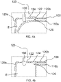
- FIG. 4a illustrates a schematic representation of the housing 100 receiving the first receiver drier variant, hereinafter referred to as the first receiver drier 110a. More specifically, the FIG. 4a depicts interaction between the movable component 124 such as for example, a flap 124 and the first receiver drier 110a, wherein the first receiver drier 110a pushes the movable component 124 radially outward and advances into the housing 100 after crossing the movable component 124.
- FIG 4b illustrates a schematic representation of the housing 100 receiving the second receiver drier variant, hereinafter referred to as the second receiver drier 110b. More specifically, the FIG. 4b depicts interaction between a rib 126 of the movable component 124, wherein the second receiver drier 110b rests on the rib 126 and is prevented from further advancing into the housing 100. Particularly, the first receiver drier 110a is comparatively longer than the second receiver drier 110b.
- the housing 100 includes at least one end wall 120a, a peripheral wall 120b, at least one slot 122, at least one movable component 124 (illustrated in FIG. 4a and FIG. 4b ).
- the at least one end wall 120a and the peripheral wall 120b define the enclosure "E" to interchangeably receive one of the at least two receiver driers 110a and 110b variants therein.
- the housing 100 is either modular in construction or is removably mounted on the bracket 210 to define an accessible enclosure.
- FIG. 1 illustrates the housing 100 in an assembled configuration with respect to the bracket 210 to define the accessible enclosure "E" there-between.
- the housing 100 is mounted on the bracket 210 that is connected to the heat exchanger 200, particularly, the condenser of an air conditioning system of a vehicle.
- the housing 100 and the bracket 210 include complementary engagement elements 128 and 214 respectively.
- the complementary engagement elements 128 and 214 formed on the housing 100 and the bracket 210 are in form of snap fit engagement elements.
- the first engagement elements 128 formed on the housing 100 are in form of latching elements received in the second engagement elements 214 that are in the form of socket formed on the bracket 210.
- the present invention is not limited to any particular configuration of the first and second engagement elements.
- the first engagement elements 128 formed on the housing 100 and the second engagement elements 214 formed on the bracket 210 engage and disengage with respect to each other to define assembled and disassembled configuration of the housing 100 with respect to the bracket 210.
- the housing 100 in conjunction with the bracket 210 defines an enclosure complementary to the receiver drier 110a, 110b to receive the receiver drier therein.
- the housing includes a first portion 100a and a second portion 100b complementary to each other, wherein the first portion 100a includes first engagement elements 128 that engage and disengage with the complementary second engagement elements 214 formed on the second portion 100b to respectively define assembled and dis-assembled configuration of the housing 100.
- the movable component 124 is formed on either one of the first portion 100a and the second portion 100b of the housing 100.
- the slot 122 along with the movable component 124 is formed on either one of the first portion 100a and the second portion 100b of the housing 100 that are complementary to each other and that in conjunction with each other define the enclosure "E" to interchangeably receive at least two receiver drier variant 110a, 110b.
- Either one of the first portion 100a and the second portion 100b is directly mounted on the heat exchanger 200.
- the housing 100 further includes additional apertures to allow passage of connecting pipes configuring fluid communication between the receiver drier received in the housing and the heat exchanger 200, particularly, the condenser.
- the present invention is not limited to any particular configuration of the housing 100 or whether the housing defines the enclose "E" independently of in conjunction with the bracket as long as the housing is capable of receiving different configuration of receiver driers, particularly, receiver driers of different lengths.
- the slot 122 can be formed on any of the walls defining the enclosure "E".
- the slot 122 is formed on the peripheral wall 120b defining the enclosure "E".
- the slot 122 is disposed proximal to the at least one end wall 120a.
- the slot 122 is formed by stamping operation.
- the slot 122 accommodates at least one of the movable component 124 and an external sensor 130, simply referred to as sensor 130 to enable at least one of the movable component 124 and the sensor 130 to interact with the receiver drier received in the enclosure "E".
- the sensor 130 is part of a manufacturing / assembly on which different receiver drier variants 110a, 110b are assembled in the housing 100 and interacts with the receiver drier 110a, 110b received inside the housing 100 through the slot 122 to determine the receiver drier variant received in the housing 100.
- the sensor 130 is triggerable in case of the first receiver drier variant 110a presence in the housing 100.
- the slot 122 is of comparatively larger dimension than the movable component 124, so that the movable component 124 can move freely across the slot 122 and space is available between the movable component 124 and the slot 122. Further, the sensor 130 interacts with the receiver drier 110a, 110b received inside the housing 100 through space between the movable component 124 and the slot 122.
- the present invention is not limited to any particular configuration, placement, number and method of forming the slot 122 as long as the slot is capable of accommodating at least one of the movable component 124 and the sensor 130 that interact with the receiver drier received in the enclosure "E" to determine the receiver drier variant.
- At least one of the movable component 124 and the sensor 130 interacts with the receiver drier received in the enclosure "E" defined by the housing 100 through the slot 122 formed on the housing 100 to identify the receiver drier variant 110a, 110b received in the enclosure "E".
- the movable component 124 is integrally formed with the housing 100.
- the movable component 124 is connected to the housing 100 along at least one side thereof and extends inwardly into the slot 122 substantially along the surface of the peripheral wall 120b.
- Such configuration of the movable component 124 provides flexibility to the movable component 124 to radially flex across the peripheral wall 120b of the housing 100 near the slot 122. Due to such flexible configuration, the movable component 124 flexes radially outward to be either aligned to the wall of the housing 100 or cause at least a portion thereof to be out of the housing 100 to define the first position of the movable component 124, when the first receiver drier 110a is received inside the housing 100.
- the movable component 124 when the movable component 124 is not interacting with second receiver drier, the movable component 124 extends inwardly in radial direction of the housing 100 into the enclosure 'E". Particularly, the movable component 124 prevents further advance of the second receiver drier 110b there across when the second receiver drier 110b is received in the housing 110.
- the receiver drier variant received inside the housing 100 can be determined.
- the receiver drier received in the housing 100 is the first receiver drier 110a else the receiver drier received in the housing 100 is the second receiver drier 110b.
- the movable component 124 further includes a cut-out to reduce weight of the movable component 124 and enable quick movement thereof when the movable component 124 interacts with the receiver drier received in the housing 100, thereby enhancing the sensitivity of the movable component 124.
- the present invention is not limited to any particular configuration, shape of the movable component 124 as long as the movable component 124 is capable of flexing radially outward in case of the first receiver drier variant 110a presence in the housing 100.
- the movable component 124 includes the rib 126 that extends into an interior of the housing 120 to push the movable component 124 radially outward, when the receiver drier received in the housing 100 is the first receiver drier 110a.
- the rib 126 interacts with the receiver drier received in the housing 100 to push the movable component 124 radially outward to indicate that the receiver drier received in the housing 100 is the first receiver drier 110a.
- the rib 126 pushes the movable component 124 to be either aligned to the peripheral wall 120b or causes at least a portion of the movable component 124 to be outside the housing 100 to indicate that the receiver drier in the housing 100 is the first receiver drier 110a .
- the rib 126 also prevents further advance of the second receiver drier 110b there across, when the second receiver drier 110b is received in the housing 100.
- the movable component 124 is capable of moving between radially inward configuration and a radially outward configuration.
- the movable component 124 In the radially inward configuration, at least a portion of the movable component 124 is inside the housing 100 to prevent the second receiver drier 110b from further advancing into the housing 100 to indicate that the receiver drier received in the housing is the second receiver drier 110b. In the radially outward configuration, the movable component 124 is either aligned with the wall of the housing 100 or at least a portion of the movable component 124 is outside the housing 100 to indicate that the receiver drier received in the housing 100 is the first receiver drier 110a . Generally, the rib 126 is disposed along a free edge of the movable component 124.
- the present invention is not limited to any particular configuration, placement and number of the ribs 126 on the movable component 124 as far as the rib 126 is capable of interacting with the receiver drier received in the housing 100 to push the movable component 124 in the radially outward direction.
- the movable component 124 can be a stepped movable component 124 that flexes radially outwardly with respect to the housing 100 when the first receiver drier 110a is received in the housing 100 but prevents further advance of the receiver driers of smaller lengths there across, when such receiver driers are received in the housing 100.
- the movable component 124 and the housing 100 are of same material.
- the movable component 124 and the housing 100 are of different material.
- the movable component 124 is formed during the forming of the slot 122 by the stamping operation.
- the slot 122 and the movable component 124 are formed together with the housing 100 by moulding process.
- the present invention is not limited to any particular configuration of the movable component 124, as long as the movable component 124 is flexible and capable of flexing to be either aligned with the peripheral wall 120b of the housing around the slot 122 or cause at least a portion thereof to be outside the housing 100, and is also capable of preventing further advance of the second receiver drier 110b there across.
- the receiver drier variant received inside the housing 100 can be determined by mere visual inspection of the movable component 124 with respect to the exterior of the housing 100 without requiring disassembly of the housing 100.
- the senor 130 can be used to determine the receiver drier version received inside the housing 100.
- the sensor 130 is part of the manufacturing / assembly on which different receiver drier variants 110a, 110b are assembled in the housing 100. More specifically, the spacing between movable component 124 and the slot 122 enables interaction between the sensor 130 and the receiver drier received inside the housing 100 to detect the receiver drier variant received inside the housing 100.
- the sensor 130 is selected from a group comprising of ultrasonic, capacitive and photoelectric sensors. Alternatively, the sensor 130 can be configured in the housing 100.
- the senor 130 is received in a pocket formed within the slot 122 on the wall 120a, 120b of the housing 120.
- the sensor 130 detects material based on whether any portion of the receiver drier received in the housing 100 comes in proximity to the sensor 130 or not.
- the sensor 130 detects that the receiver drier received inside the housing 100 is the first receiver drier 110a based on whether the receiver drier reaches in front of the sensor 130 or not.
- Such configuration enables the sensor 130 to determine the receiver drier variant without contacting the receiver drier.
- an audio or visual indication may be provided.
- the present invention applies different features to determine the receiver drier variant received inside the housing 100.
- the sensor 130 determines the receiver drier variant received in the housing 100 based on the principle of material detection.
- the movable component 124 determines the receiver drier variant received in the housing 100 based on mechanical interaction of the movable component 124 with respect to the receiver drier receiver drier and deformation of the movable component 124 due to such mechanical interaction.
- Such configuration provides redundancy by determining the receiver drier variant received in the housing 100 even in case one feature fails to determine the receiver drier variant inside the housing 100.
- the receiver drier variant received in the housing can still be determined, even if the movable component 124 fails due to wear and tear due to usage of the movable component 124 over a period of time or if the sensor fails due to any other reason.
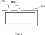
- FIG. 5 present another embodiment of the invention.
- the housing includes a first indication 125a means and a second indication 125b means.
- the first indication means 125a moves to the first position based on length of the receiver drier variant received in the housing 100 and the second indication means 125b moves to the first position based on radial dimension of the receiver drier variant received in the housing 100.
- the present invention is explained with example of a housing configured with a slot, wherein at least one movable component 124 and a sensor interacts through the slot with the receiver drier held inside the housing to determine whether the receiver drier is any one of the two variants.
- duplication and changing arrangement of the slots on the housing, wherein the respective movable components and sensors interact with the receiver drier received in the housing to determine different receiver drier variants will still be within the scope of the present invention.
- housing configured with a slot
- at least one movable component and a sensor interacts through the slot with the receiver drier held inside the housing to determine whether a receiver drier of particular length is received in the housing.
- housing of such configuration with slot, wherein at least one of movable component and sensor interacts through the slot with the receiver drier can be used to determine different sizes, particularly, different volumes and diameters of the receiver driers received in the housing.
- the heat exchanger 200 includes a housing 100 connected thereto.
- the housing 100 receives and holds different receiver drier variants therein, wherein the housing 100 is as disclosed above. More specifically, the housing 100 includes features to determine the receiver drier variants received in the housing 100.
Landscapes
- Engineering & Computer Science (AREA)
- Chemical & Material Sciences (AREA)
- Analytical Chemistry (AREA)
- Power Engineering (AREA)
- Physics & Mathematics (AREA)
- Mechanical Engineering (AREA)
- Thermal Sciences (AREA)
- General Engineering & Computer Science (AREA)
- Air-Conditioning For Vehicles (AREA)
- Detail Structures Of Washing Machines And Dryers (AREA)
Abstract
Description
- The present invention relates to a heat exchanger assembly, particularly a receiver drier housing to receive a receiver drier and connected to a heat exchanger.
- Conventional air conditioning system, for example, air conditioning system for a vehicle, includes a condenser, an evaporator, an expansion device, a compressor and a heater. Generally, the conventional air conditioning system configured with an expansion valve is also configured with a receiver drier that is disposed in a highpressure section of the air conditioning system/ air conditioning loop. The receiver drier is usually located between a condenser and the expansion valve in the air conditioning loop. The receiver drier traps moisture and debris carried with condensed refrigerant received from the condenser. Accordingly, moisture and debris that is detrimental to critical components such as compressor disposed in the air-conditioning loop is prevented from reaching the compressor. The receiver drier is disposed near the condenser. Preferably, the receiver drier is received in a receiver drier housing that is mounted on the condenser.
- However, different variants of condensers are used corresponding to different configurations of the air conditioning systems. Accordingly, different configurations / versions/ variants of receiver driers are used corresponding to different configurations of the condenser. For example, different sizes of receiver drier are used corresponding to different sizes of the condensers. In some cases, a receiver drier housing is used to receive and house different configurations of the receiver drier, for example different sizes of the receiver driers. A common (i.e. standard) receiver drier housing is preferred over non-standard receiver drier housing, wherein a different receiver drier housing is used to receive different configuration, particularly, different size of the receiver drier. The use of a non-standard receiver drier not only increases the manufacturing costs but also increases the assembly time. This problem is aggravated when there are many variants of the receiver drier. The standard receiver drier housing addresses the above problems. However, it is to be ensured that a particular configuration / version/ variant of receiver drier, for example, a particular size of receiver drier corresponding to a particular condenser size/type is received in the standard housing mounted on the condenser during assembly of the air conditioning system.
- In case a wrong variant of receiver drier corresponding to a particular configuration of the condenser is received in the receiver drier housing, the performance parameters associated with the air conditioning system deviates from intended values, thereby detrimentally affecting the efficiency and the performance of the air conditioning system. Accordingly, it is to be ensured that right variant of the receiver drier corresponding to a particular configuration of the condenser is received in the standard receiver drier housing.
- As the conventional receiver drier housing completely encloses the receiver drier, it is difficult to determine the variant of the receiver drier received in the receiver drier housing by visual inspection from outside the receiver drier housing. The receiver drier housing is either modular or is removably mounted on a bracket to define an accessible enclosure. In case the receiver drier housing is mounted on the bracket connected to the condenser, the receiver drier housing and the bracket include complementary engagement elements. More specifically, complementary engagement elements formed on the receiver drier housing and the bracket engage and disengage with respect to each other to define assembled and disassembled configuration of the receiver drier housing with respect to the bracket. In the assembled configuration, the receiver drier housing in conjunction with the bracket defines an enclosure complementary to the receiver drier to receive the receiver drier therein. Such modular configuration enables dis-assembly of the receiver drier housing from the bracket to access the receiver drier received in the enclosure for service/ maintenance and replacement thereof. The conventional receiver drier housing is required to be dis-assembled to access, inspect and determine the variant of the receiver drier received in the enclosure and re-assembled. However, such process is inconvenient and time consuming. Further, in case of the conventional receiver drier housing, there is no indication to determine the variant of the receiver drier received in the receiver drier housing without disassembling the receiver drier housing.
- Accordingly, there is a need for a receiver drier housing that obviates the problems faced by the conventional receiver drier housing. Particularly, there is a need for a receiver drier housing that enables determining a variant of a receiver drier received in the receiver drier housing without dis-assembling the receiver drier housing. Further, there is a need for a receiver drier housing configured with redundant features to determine the variant of receiver drier received in the receiver drier housing. Particularly, there is a need for a failsafe arrangement that involves more than one feature to determine the variant of the receiver drier received inside the receiver drier housing, wherein one feature still determines the variant of the receiver drier received in the housing even when other feature fails.
- An object of the present invention is to provide a receiver drier housing that is simple in construction and that is configured with redundant features to determine the variant of the receiver drier received in the receiver drier housing without the need for disassembling the receiver drier housing.
- In the present description, some elements or parameters may be indexed, such as a first element and a second element. In this case, unless stated otherwise, this indexation is only meant to differentiate and name elements which are similar but not identical. No idea of priority should be inferred from such indexation, as these terms may be switched without betraying the invention. Additionally, this indexation does not imply any order in mounting or use of the elements of the invention.
- A housing is disclosed in accordance with an embodiment of the present invention. The housing house interchangeably at least two receiver drier variants. The housing includes indication means that moves between a first position indicative of presence of a first receiver drier variant and a second position indicative of presence of a second receiver drier variant. One of the positions may also be indicative of the absence of any receiver drier.
- Generally, the indication means includes at least one movable component that moves between a first position and a second position due to mechanical interaction thereof with the first receiver drier variant.
- Further, the housing includes a slot for an external sensor triggerable in case of the first receiver drier variant presence in the housing.
- Generally, the at least one slot is disposed proximal to the at least one end wall of the housing.
- Particularly, the slot receives the movable component.
- More specifically, the movable component extends inwardly into the slot along the wall and at least a portion thereof extends radially inward into an interior of the housing.
- Specifically, the movable component is integrally formed with the housing and is connected to the housing along at least one side thereof.
- Particularly, the movable component is flexible and flexes radially outward, to cause at least a portion thereof to be out of the housing when the first receiver drier variant is received in the housing.
- Alternatively, the movable component further includes a rib extending into an interior of the housing that pushes at least a portion of the movable component out of the housing when the first receiver drier variant is received in the housing.
- Generally, the indication means moves to the first position based on length of the receiver drier variant received in the housing.
- Alternatively, the indication means moves to the first position based on radial dimension of the receiver drier variant received in the housing.
- In accordance with an embodiment of the present invention, the housing includes a first indication means and a second indication means. The first indication means moves to the first position based on length of the receiver drier variant received in the housing and the second indication means moves to the first position based on radial dimension of the receiver drier variant received in the housing.
- Also is disclosed a heat exchanger that includes a housing connected thereto to receive and hold different receiver drier variants therein, wherein the housing is as disclosed above.
- Other characteristics, details and advantages of the invention can be inferred from the description of the invention hereunder. A more complete appreciation of the invention and many of the attendant advantages thereof will be readily obtained as the same becomes better understood by reference to the following detailed description when considered in connection with the accompanying figures, wherein:
-
FIG.1 illustrates an isometric view of a housing in accordance with an embodiment of the present invention in an assembled configuration with respect to a bracket; -
FIG. 2 illustrates an isometric view of the housing ofFIG. 1 ; -
FIG. 3 illustrates an isometric view of the bracket ofFIG. 1 ; -
FIG. 4a illustrates a schematic representation of a housing receiving a first receiver drier; -
FIG. 4b illustrates a schematic representation of the housing ofFIG. 4a receiving a second receiver drier; -
FIG. 5 presents another embodiment of the invention. - Although, the present invention relates to a housing defining an enclosure for interchangeably receiving at least two receiver drier variants. Particularly, the housing includes an indication means that moves between a first position indicative of presence of the first receiver drier variant and a second position indicative of presence of the second receiver drier variant. More specifically, the housing includes at least one end wall, a peripheral wall, at least one slot and a movable component. The movable component moves between a first position and a second position due to mechanical interaction thereof with the first receiver drier variant. The at least one end wall and a peripheral wall define the enclosure to interchangeably receive one of the at least two receiver drier variants therein. The slot is formed on any of the walls defining the enclosure. The movable element interacts with the receiver drier received inside the housing through the slot to determine the receiver drier variant received in the housing. Further, an external sensor that is part of a manufacturing / assembly on which different receiver drier variants are assembled in the housing interacts with the receiver drier received inside the housing through the slot to determine the receiver drier variant. The external sensor is triggerable in case of the first receiver drier variant presence in the housing. At least one of the movable component and the external sensor interacts with the receiver drier through the slot to identify the receiver drier variant received in the enclosure. However, the present invention is not limited to a housing that defines enclosure for interchangeably receiving at least two receiver drier variants and is configured with features to determine the receiver drier variant received therein. The housing can be used to receive different tubular articles used in vehicular and non-vehicular applications, wherein it is required to determine variant of tubular article received in the housing by mere visual inspection of an exterior of the housing without requiring dis-assembly of the housing.
-
FIG.1 illustrates an isometric view of a receiverdrier housing 100, hereinafter referred to ashousing 100 in accordance with an embodiment of the present invention. In one example, thehousing 100 is mounted on abracket 210 complementary to thehousing 100. Thebracket 210 in turn is mounted on a heat exchanger 200 for a vehicle. More specifically, thebracket 210 includes mountingholes 212 configured thereon. The mounting holes 212 on thebracket 210 are aligned to corresponding complementary mounting holes on the heat exchanger 200 and bolts pass through the aligned mountingholes 212 on thebracket 210 and the mounting holes on the heat exchanger 200 to mount thebracket 210 to the heat exchanger 200.FIG. 2 illustrates an isometric view of thehousing 100.FIG. 3 illustrates an isometric view of thebracket 210. - The
housing 100 at least partially houses interchangeably at least two receiverdrier variants housing 100 includes indication means 125 that moves between a first position indicative of presence of a first receiverdrier variant 110a and a second position indicative of presence of a second receiverdrier variant 110b. - Generally, the indication means 125 moves to the first position based on length of the receiver drier variant received in the
housing 100. More specifically, the indication means 125 moves to the first position when the first receiverdrier version 110a that is comparatively longer than the second receiverdrier version 110b is received in thehousing 100. Alternatively, the indication means 125 moves to the first position based on radial dimension of the receiver drier variant received in thehousing 100. More specifically, the indication means 125 moves to the first position when the first receiverdrier version 110a that is comparatively larger radial dimension than the second receiverdrier version 110b is received in thehousing 100. In accordance with an embodiment of the present invention, the housing includes a first indication means and a second indication means. The first indication means 125a moves to the first position based on length of the receiver drier variant received in thehousing 100 and the second indication means 125b moves to the first position based on radial dimension of the receiver drier variant received in thehousing 100. - The indication means 125 include at least one
movable component 124 that moves between a first position and a second position due to mechanical interaction thereof with the first receiverdrier variant 110a received in thehousing 100.FIG. 4a illustrates a schematic representation of thehousing 100 receiving the first receiver drier variant, hereinafter referred to as the first receiver drier 110a. More specifically, theFIG. 4a depicts interaction between themovable component 124 such as for example, aflap 124 and the first receiver drier 110a, wherein the first receiver drier 110a pushes themovable component 124 radially outward and advances into thehousing 100 after crossing themovable component 124.FIG 4b illustrates a schematic representation of thehousing 100 receiving the second receiver drier variant, hereinafter referred to as the second receiver drier 110b. More specifically, theFIG. 4b depicts interaction between arib 126 of themovable component 124, wherein the second receiver drier 110b rests on therib 126 and is prevented from further advancing into thehousing 100. Particularly, the first receiver drier 110a is comparatively longer than the second receiver drier 110b. Thehousing 100 includes at least oneend wall 120a, aperipheral wall 120b, at least oneslot 122, at least one movable component 124 (illustrated inFIG. 4a and FIG. 4b ). - The at least one
end wall 120a and theperipheral wall 120b define the enclosure "E" to interchangeably receive one of the at least tworeceiver driers housing 100 is either modular in construction or is removably mounted on thebracket 210 to define an accessible enclosure.FIG. 1 illustrates thehousing 100 in an assembled configuration with respect to thebracket 210 to define the accessible enclosure "E" there-between. Specifically, thehousing 100 is mounted on thebracket 210 that is connected to the heat exchanger 200, particularly, the condenser of an air conditioning system of a vehicle. Thehousing 100 and thebracket 210 includecomplementary engagement elements complementary engagement elements housing 100 and thebracket 210 are in form of snap fit engagement elements. Thefirst engagement elements 128 formed on thehousing 100 are in form of latching elements received in thesecond engagement elements 214 that are in the form of socket formed on thebracket 210. However, the present invention is not limited to any particular configuration of the first and second engagement elements. Thefirst engagement elements 128 formed on thehousing 100 and thesecond engagement elements 214 formed on thebracket 210 engage and disengage with respect to each other to define assembled and disassembled configuration of thehousing 100 with respect to thebracket 210. In the assembled configuration, thehousing 100 in conjunction with thebracket 210 defines an enclosure complementary to the receiver drier 110a, 110b to receive the receiver drier therein. Such configuration, enables dis-assembly of thehousing 100 with respect to thebracket 210 to access the receiver drier 110a, 110b received in the enclosure "E" for service / maintenance and replacement thereof. Alternatively, the housing includes a first portion 100a and a second portion 100b complementary to each other, wherein the first portion 100a includesfirst engagement elements 128 that engage and disengage with the complementarysecond engagement elements 214 formed on the second portion 100b to respectively define assembled and dis-assembled configuration of thehousing 100. Themovable component 124 is formed on either one of the first portion 100a and the second portion 100b of thehousing 100. More specifically, theslot 122 along with themovable component 124 is formed on either one of the first portion 100a and the second portion 100b of thehousing 100 that are complementary to each other and that in conjunction with each other define the enclosure "E" to interchangeably receive at least two receiverdrier variant housing 100 further includes additional apertures to allow passage of connecting pipes configuring fluid communication between the receiver drier received in the housing and the heat exchanger 200, particularly, the condenser. However, the present invention is not limited to any particular configuration of thehousing 100 or whether the housing defines the enclose "E" independently of in conjunction with the bracket as long as the housing is capable of receiving different configuration of receiver driers, particularly, receiver driers of different lengths. - Generally, the
slot 122 can be formed on any of the walls defining the enclosure "E". Preferably, theslot 122 is formed on theperipheral wall 120b defining the enclosure "E". Theslot 122 is disposed proximal to the at least oneend wall 120a. Theslot 122 is formed by stamping operation. Theslot 122 accommodates at least one of themovable component 124 and anexternal sensor 130, simply referred to assensor 130 to enable at least one of themovable component 124 and thesensor 130 to interact with the receiver drier received in the enclosure "E". Thesensor 130 is part of a manufacturing / assembly on which different receiverdrier variants housing 100 and interacts with the receiver drier 110a, 110b received inside thehousing 100 through theslot 122 to determine the receiver drier variant received in thehousing 100. Thesensor 130 is triggerable in case of the first receiverdrier variant 110a presence in thehousing 100. Theslot 122 is of comparatively larger dimension than themovable component 124, so that themovable component 124 can move freely across theslot 122 and space is available between themovable component 124 and theslot 122. Further, thesensor 130 interacts with the receiver drier 110a, 110b received inside thehousing 100 through space between themovable component 124 and theslot 122. However, the present invention is not limited to any particular configuration, placement, number and method of forming theslot 122 as long as the slot is capable of accommodating at least one of themovable component 124 and thesensor 130 that interact with the receiver drier received in the enclosure "E" to determine the receiver drier variant. - At least one of the
movable component 124 and thesensor 130 interacts with the receiver drier received in the enclosure "E" defined by thehousing 100 through theslot 122 formed on thehousing 100 to identify the receiverdrier variant - The
movable component 124 is integrally formed with thehousing 100. Themovable component 124 is connected to thehousing 100 along at least one side thereof and extends inwardly into theslot 122 substantially along the surface of theperipheral wall 120b. Such configuration of themovable component 124 provides flexibility to themovable component 124 to radially flex across theperipheral wall 120b of thehousing 100 near theslot 122. Due to such flexible configuration, themovable component 124 flexes radially outward to be either aligned to the wall of thehousing 100 or cause at least a portion thereof to be out of thehousing 100 to define the first position of themovable component 124, when the first receiver drier 110a is received inside thehousing 100. In another configuration, when themovable component 124 is not interacting with second receiver drier, themovable component 124 extends inwardly in radial direction of thehousing 100 into the enclosure 'E". Particularly, themovable component 124 prevents further advance of the second receiver drier 110b there across when the second receiver drier 110b is received in the housing 110. By visually inspecting relative position of themovable component 124 with respect to theperipheral wall 120b, the receiver drier variant received inside thehousing 100 can be determined. For example, in case themovable component 124 is either aligned to theperipheral wall 120b or at least a portion of themovable component 124 extends out of thehousing 100, the receiver drier received in thehousing 100 is the first receiver drier 110a else the receiver drier received in thehousing 100 is the second receiver drier 110b. Themovable component 124 further includes a cut-out to reduce weight of themovable component 124 and enable quick movement thereof when themovable component 124 interacts with the receiver drier received in thehousing 100, thereby enhancing the sensitivity of themovable component 124. However, the present invention is not limited to any particular configuration, shape of themovable component 124 as long as themovable component 124 is capable of flexing radially outward in case of the first receiverdrier variant 110a presence in thehousing 100. - In accordance with an embodiment depicted in
FIG. 4a and FIG. 4b , themovable component 124 includes therib 126 that extends into an interior of the housing 120 to push themovable component 124 radially outward, when the receiver drier received in thehousing 100 is the first receiver drier 110a. Specifically, therib 126 interacts with the receiver drier received in thehousing 100 to push themovable component 124 radially outward to indicate that the receiver drier received in thehousing 100 is the first receiver drier 110a. More specifically, therib 126 pushes themovable component 124 to be either aligned to theperipheral wall 120b or causes at least a portion of themovable component 124 to be outside thehousing 100 to indicate that the receiver drier in thehousing 100 is the first receiver drier 110a. Therib 126 also prevents further advance of the second receiver drier 110b there across, when the second receiver drier 110b is received in thehousing 100. More specifically, themovable component 124 is capable of moving between radially inward configuration and a radially outward configuration. In the radially inward configuration, at least a portion of themovable component 124 is inside thehousing 100 to prevent the second receiver drier 110b from further advancing into thehousing 100 to indicate that the receiver drier received in the housing is the second receiver drier 110b. In the radially outward configuration, themovable component 124 is either aligned with the wall of thehousing 100 or at least a portion of themovable component 124 is outside thehousing 100 to indicate that the receiver drier received in thehousing 100 is the first receiver drier 110a. Generally, therib 126 is disposed along a free edge of themovable component 124. However, the present invention is not limited to any particular configuration, placement and number of theribs 126 on themovable component 124 as far as therib 126 is capable of interacting with the receiver drier received in thehousing 100 to push themovable component 124 in the radially outward direction. - Instead of the
rib 126, themovable component 124 can be a steppedmovable component 124 that flexes radially outwardly with respect to thehousing 100 when the first receiver drier 110a is received in thehousing 100 but prevents further advance of the receiver driers of smaller lengths there across, when such receiver driers are received in thehousing 100. Generally, themovable component 124 and thehousing 100 are of same material. Alternatively, themovable component 124 and thehousing 100 are of different material. Themovable component 124 is formed during the forming of theslot 122 by the stamping operation. Alternatively, theslot 122 and themovable component 124 are formed together with thehousing 100 by moulding process. However, the present invention is not limited to any particular configuration of themovable component 124, as long as themovable component 124 is flexible and capable of flexing to be either aligned with theperipheral wall 120b of the housing around theslot 122 or cause at least a portion thereof to be outside thehousing 100, and is also capable of preventing further advance of the second receiver drier 110b there across. With such configuration, the receiver drier variant received inside thehousing 100 can be determined by mere visual inspection of themovable component 124 with respect to the exterior of thehousing 100 without requiring disassembly of thehousing 100. - Instead of the
movable component 124 or in addition to themovable component 124 formed on thehousing 100 to determine the receiver drier version received inside thehousing 100, thesensor 130 can be used to determine the receiver drier version received inside thehousing 100. Generally, thesensor 130 is part of the manufacturing / assembly on which different receiverdrier variants housing 100. More specifically, the spacing betweenmovable component 124 and theslot 122 enables interaction between thesensor 130 and the receiver drier received inside thehousing 100 to detect the receiver drier variant received inside thehousing 100. Thesensor 130 is selected from a group comprising of ultrasonic, capacitive and photoelectric sensors. Alternatively, thesensor 130 can be configured in thehousing 100. More specifically, thesensor 130 is received in a pocket formed within theslot 122 on thewall sensor 130 detects material based on whether any portion of the receiver drier received in thehousing 100 comes in proximity to thesensor 130 or not. Specifically, thesensor 130 detects that the receiver drier received inside thehousing 100 is the first receiver drier 110a based on whether the receiver drier reaches in front of thesensor 130 or not. Such configuration enables thesensor 130 to determine the receiver drier variant without contacting the receiver drier. Based on the detection of the first receiver drier 110a by thesensor 130, an audio or visual indication may be provided. The present invention applies different features to determine the receiver drier variant received inside thehousing 100. More specifically, thesensor 130 determines the receiver drier variant received in thehousing 100 based on the principle of material detection. Whereas themovable component 124 determines the receiver drier variant received in thehousing 100 based on mechanical interaction of themovable component 124 with respect to the receiver drier receiver drier and deformation of themovable component 124 due to such mechanical interaction. Such configuration provides redundancy by determining the receiver drier variant received in thehousing 100 even in case one feature fails to determine the receiver drier variant inside thehousing 100. With such configuration, the receiver drier variant received in the housing can still be determined, even if themovable component 124 fails due to wear and tear due to usage of themovable component 124 over a period of time or if the sensor fails due to any other reason. -
FIG. 5 present another embodiment of the invention. In this example, the housing includes afirst indication 125a means and asecond indication 125b means. The first indication means 125a moves to the first position based on length of the receiver drier variant received in thehousing 100 and the second indication means 125b moves to the first position based on radial dimension of the receiver drier variant received in thehousing 100. - Although, the present invention is explained with example of a housing configured with a slot, wherein at least one
movable component 124 and a sensor interacts through the slot with the receiver drier held inside the housing to determine whether the receiver drier is any one of the two variants. However, there could be multiple slots, with respective movable components and sensors interacting through such slots with the receiver drier received in the housing to determine different receiver drier variants. More specifically, duplication and changing arrangement of the slots on the housing, wherein the respective movable components and sensors interact with the receiver drier received in the housing to determine different receiver drier variants will still be within the scope of the present invention. Further, although, the present invention is explained with example of a housing configured with a slot, wherein at least one movable component and a sensor interacts through the slot with the receiver drier held inside the housing to determine whether a receiver drier of particular length is received in the housing. However, housing of such configuration with slot, wherein at least one of movable component and sensor interacts through the slot with the receiver drier can be used to determine different sizes, particularly, different volumes and diameters of the receiver driers received in the housing. - Also is disclosed a heat exchanger 200 in accordance with an embodiment of the present invention. The heat exchanger 200 includes a
housing 100 connected thereto. Thehousing 100 receives and holds different receiver drier variants therein, wherein thehousing 100 is as disclosed above. More specifically, thehousing 100 includes features to determine the receiver drier variants received in thehousing 100.
Claims (13)
- A housing (100) adapted to house interchangeably at least two receiver drier variants (110a, 110b), the housing (100) comprising indication means (125) adapted to move between a first position indicative of presence of a first receiver drier variant (110a) and a second position indicative of presence of a second receiver drier variant (110b).
- The housing (100) in accordance with the previous claim, wherein the indication means (125) comprises at least one movable component (124) adapted to move between a first position and a second position due to mechanical interaction thereof with the first receiver drier variant (110a).
- The housing (100) in accordance with any of the preceding claims, further comprising a slot (122) for an external sensor (130) triggerable in case of the first receiver drier variant (110a) presence in the housing (100).
- The housing (100) as claimed in any of the previous claim, wherein the slot (122) is disposed proximal to the at least one end wall (120a) of the housing (100).
- The housing (100) as claimed in claim 3, wherein the slot (122) is adapted to receive the movable component (124).
- The housing (100) as claimed in claim 3 or 5, wherein the movable component (124) extends inwardly into the slot (122) along the wall (120a, 120b) and at least a portion thereof extends radially into an interior of the housing (100).
- The housing (100) as claimed in any of claims 2-6, wherein the movable component (124) is integrally formed with the housing (100) and is connected to the housing (100) along at least one side thereof.
- The housing (100) as claimed in any of claims 2-7, wherein the movable component (124) is flexible and flexes radially outward to cause at least a portion thereof to be out of the housing (100) when the first receiver drier variant (110a) is received inside the housing (100).
- The housing (100) as claimed in any of claims 2-8, wherein the movable component (124) further comprises a rib (126) extending into an interior of the housing (120) that pushes at least a portion of the movable component (124) outside the housing (100) when the first receiver drier variant (110a) is received in the housing (100).
- The housing (100) as claimed in any of the preceding claims, wherein the indication means (125) is adapted to move to the first position based on length of the receiver drier variant received in the housing (100).
- The housing (100) as claimed in any of the preceding claims, wherein the indication means (125) is adapted to move to the first position based on radial dimension of the receiver drier variant received in the housing (100).
- The housing (100) as claimed in any of the preceding claims comprises a first indication means (125a) and a second indication means (125b), wherein the first indication means (125a) is adapted to move to the first position based on length of the receiver drier variant received in the housing (100) and the second indication means (125b) is adapted to move to the first position based on radial dimension of the receiver drier variant received in the housing (100).
- A heat exchanger (200) comprising a housing (100) as claimed in any of the preceding claims, wherein the heat exchanger (200) comprises a first receiver drier variant (110a) or second receiver drier variant (110b).
Priority Applications (1)
| Application Number | Priority Date | Filing Date | Title |
|---|---|---|---|
| EP20461563.7A EP3978837B1 (en) | 2020-09-30 | 2020-09-30 | A receiver drier housing |
Applications Claiming Priority (1)
| Application Number | Priority Date | Filing Date | Title |
|---|---|---|---|
| EP20461563.7A EP3978837B1 (en) | 2020-09-30 | 2020-09-30 | A receiver drier housing |
Publications (2)
| Publication Number | Publication Date |
|---|---|
| EP3978837A1 true EP3978837A1 (en) | 2022-04-06 |
| EP3978837B1 EP3978837B1 (en) | 2023-06-21 |
Family
ID=72717830
Family Applications (1)
| Application Number | Title | Priority Date | Filing Date |
|---|---|---|---|
| EP20461563.7A Active EP3978837B1 (en) | 2020-09-30 | 2020-09-30 | A receiver drier housing |
Country Status (1)
| Country | Link |
|---|---|
| EP (1) | EP3978837B1 (en) |
Citations (3)
| Publication number | Priority date | Publication date | Assignee | Title |
|---|---|---|---|---|
| US3785164A (en) * | 1972-05-17 | 1974-01-15 | Virginia Chemicals Inc | Precharged receiver drier for automobile air conditioning systems |
| EP3193105A2 (en) * | 2016-01-13 | 2017-07-19 | Bergstrom, Inc. | Refrigeration system with superheating, subcooling and refrigerant charge level control |
| EP3444544A1 (en) * | 2017-08-17 | 2019-02-20 | VALEO AUTOSYSTEMY Sp. Z. o.o. | Heat exchanging module |
-
2020
- 2020-09-30 EP EP20461563.7A patent/EP3978837B1/en active Active
Patent Citations (3)
| Publication number | Priority date | Publication date | Assignee | Title |
|---|---|---|---|---|
| US3785164A (en) * | 1972-05-17 | 1974-01-15 | Virginia Chemicals Inc | Precharged receiver drier for automobile air conditioning systems |
| EP3193105A2 (en) * | 2016-01-13 | 2017-07-19 | Bergstrom, Inc. | Refrigeration system with superheating, subcooling and refrigerant charge level control |
| EP3444544A1 (en) * | 2017-08-17 | 2019-02-20 | VALEO AUTOSYSTEMY Sp. Z. o.o. | Heat exchanging module |
Also Published As
| Publication number | Publication date |
|---|---|
| EP3978837B1 (en) | 2023-06-21 |
Similar Documents
| Publication | Publication Date | Title |
|---|---|---|
| US10485128B2 (en) | Compressor protection module | |
| JP7004836B2 (en) | Refrigeration cycle device | |
| US20160230763A1 (en) | Rotary Compressor With Vapor Injection System | |
| US20210041114A1 (en) | Indoor unit of air-conditioning apparatus, and air-conditioning apparatus including the indoor unit | |
| WO2007081192A2 (en) | Discharge valve assembly for linear compressor | |
| WO2007073052A1 (en) | Housing for modulizing heat pump system in a clothes dryer and clothes dryer having the same | |
| US20090119944A1 (en) | Clothing dryer | |
| EP3978837B1 (en) | A receiver drier housing | |
| CN110541802A (en) | Structure and method for preventing/reducing noise for refrigerator | |
| JP7309077B2 (en) | Compressor and outdoor unit of air conditioner equipped with the compressor | |
| EP2075473A1 (en) | Fan Module | |
| JP2003075057A (en) | Piping holding members for electric refrigerators | |
| KR101644437B1 (en) | Turbo chiller | |
| EP3104096B1 (en) | Drain pan and air conditioner | |
| CN111219518A (en) | Electronic expansion valve | |
| AU2019479344B2 (en) | Temperature-sensor fixing device and compressor | |
| KR101478702B1 (en) | Temperature sensor assembling structure of evaporator for car air conditioning system | |
| US20230408141A1 (en) | Compressor isolation molded insert | |
| CN223360825U (en) | Sensor fixtures and air conditioners | |
| US20250389430A1 (en) | Air conditioner | |
| CN224121483U (en) | A pipe support device and a refrigerator | |
| KR20000000305U (en) | Compressor Assembly | |
| CN222376705U (en) | Compressor structure | |
| EP3995762B1 (en) | A receiver drier bottle assembly | |
| KR100333819B1 (en) | Control box for air-conditioner |
Legal Events
| Date | Code | Title | Description |
|---|---|---|---|
| PUAI | Public reference made under article 153(3) epc to a published international application that has entered the european phase |
Free format text: ORIGINAL CODE: 0009012 |
|
| STAA | Information on the status of an ep patent application or granted ep patent |
Free format text: STATUS: THE APPLICATION HAS BEEN PUBLISHED |
|
| AK | Designated contracting states |
Kind code of ref document: A1 Designated state(s): AL AT BE BG CH CY CZ DE DK EE ES FI FR GB GR HR HU IE IS IT LI LT LU LV MC MK MT NL NO PL PT RO RS SE SI SK SM TR |
|
| STAA | Information on the status of an ep patent application or granted ep patent |
Free format text: STATUS: REQUEST FOR EXAMINATION WAS MADE |
|
| 17P | Request for examination filed |
Effective date: 20221006 |
|
| RBV | Designated contracting states (corrected) |
Designated state(s): AL AT BE BG CH CY CZ DE DK EE ES FI FR GB GR HR HU IE IS IT LI LT LU LV MC MK MT NL NO PL PT RO RS SE SI SK SM TR |
|
| GRAP | Despatch of communication of intention to grant a patent |
Free format text: ORIGINAL CODE: EPIDOSNIGR1 |
|
| STAA | Information on the status of an ep patent application or granted ep patent |
Free format text: STATUS: GRANT OF PATENT IS INTENDED |
|
| INTG | Intention to grant announced |
Effective date: 20230126 |
|
| GRAS | Grant fee paid |
Free format text: ORIGINAL CODE: EPIDOSNIGR3 |
|
| GRAA | (expected) grant |
Free format text: ORIGINAL CODE: 0009210 |
|
| STAA | Information on the status of an ep patent application or granted ep patent |
Free format text: STATUS: THE PATENT HAS BEEN GRANTED |
|
| AK | Designated contracting states |
Kind code of ref document: B1 Designated state(s): AL AT BE BG CH CY CZ DE DK EE ES FI FR GB GR HR HU IE IS IT LI LT LU LV MC MK MT NL NO PL PT RO RS SE SI SK SM TR |
|
| REG | Reference to a national code |
Ref country code: CH Ref legal event code: EP |
|
| REG | Reference to a national code |
Ref country code: DE Ref legal event code: R096 Ref document number: 602020012755 Country of ref document: DE |
|
| P01 | Opt-out of the competence of the unified patent court (upc) registered |
Effective date: 20230528 |
|
| REG | Reference to a national code |
Ref country code: AT Ref legal event code: REF Ref document number: 1581144 Country of ref document: AT Kind code of ref document: T Effective date: 20230715 |
|
| REG | Reference to a national code |
Ref country code: IE Ref legal event code: FG4D |
|
| REG | Reference to a national code |
Ref country code: LT Ref legal event code: MG9D |
|
| REG | Reference to a national code |
Ref country code: NL Ref legal event code: MP Effective date: 20230621 |
|
| PG25 | Lapsed in a contracting state [announced via postgrant information from national office to epo] |
Ref country code: SE Free format text: LAPSE BECAUSE OF FAILURE TO SUBMIT A TRANSLATION OF THE DESCRIPTION OR TO PAY THE FEE WITHIN THE PRESCRIBED TIME-LIMIT Effective date: 20230621 Ref country code: NO Free format text: LAPSE BECAUSE OF FAILURE TO SUBMIT A TRANSLATION OF THE DESCRIPTION OR TO PAY THE FEE WITHIN THE PRESCRIBED TIME-LIMIT Effective date: 20230921 |
|
| REG | Reference to a national code |
Ref country code: AT Ref legal event code: MK05 Ref document number: 1581144 Country of ref document: AT Kind code of ref document: T Effective date: 20230621 |
|
| PG25 | Lapsed in a contracting state [announced via postgrant information from national office to epo] |
Ref country code: RS Free format text: LAPSE BECAUSE OF FAILURE TO SUBMIT A TRANSLATION OF THE DESCRIPTION OR TO PAY THE FEE WITHIN THE PRESCRIBED TIME-LIMIT Effective date: 20230621 Ref country code: NL Free format text: LAPSE BECAUSE OF FAILURE TO SUBMIT A TRANSLATION OF THE DESCRIPTION OR TO PAY THE FEE WITHIN THE PRESCRIBED TIME-LIMIT Effective date: 20230621 Ref country code: LV Free format text: LAPSE BECAUSE OF FAILURE TO SUBMIT A TRANSLATION OF THE DESCRIPTION OR TO PAY THE FEE WITHIN THE PRESCRIBED TIME-LIMIT Effective date: 20230621 Ref country code: LT Free format text: LAPSE BECAUSE OF FAILURE TO SUBMIT A TRANSLATION OF THE DESCRIPTION OR TO PAY THE FEE WITHIN THE PRESCRIBED TIME-LIMIT Effective date: 20230621 Ref country code: HR Free format text: LAPSE BECAUSE OF FAILURE TO SUBMIT A TRANSLATION OF THE DESCRIPTION OR TO PAY THE FEE WITHIN THE PRESCRIBED TIME-LIMIT Effective date: 20230621 Ref country code: GR Free format text: LAPSE BECAUSE OF FAILURE TO SUBMIT A TRANSLATION OF THE DESCRIPTION OR TO PAY THE FEE WITHIN THE PRESCRIBED TIME-LIMIT Effective date: 20230922 |
|
| PG25 | Lapsed in a contracting state [announced via postgrant information from national office to epo] |
Ref country code: FI Free format text: LAPSE BECAUSE OF FAILURE TO SUBMIT A TRANSLATION OF THE DESCRIPTION OR TO PAY THE FEE WITHIN THE PRESCRIBED TIME-LIMIT Effective date: 20230621 |
|
| PG25 | Lapsed in a contracting state [announced via postgrant information from national office to epo] |
Ref country code: SK Free format text: LAPSE BECAUSE OF FAILURE TO SUBMIT A TRANSLATION OF THE DESCRIPTION OR TO PAY THE FEE WITHIN THE PRESCRIBED TIME-LIMIT Effective date: 20230621 |
|
| PG25 | Lapsed in a contracting state [announced via postgrant information from national office to epo] |
Ref country code: ES Free format text: LAPSE BECAUSE OF FAILURE TO SUBMIT A TRANSLATION OF THE DESCRIPTION OR TO PAY THE FEE WITHIN THE PRESCRIBED TIME-LIMIT Effective date: 20230621 |
|
| PG25 | Lapsed in a contracting state [announced via postgrant information from national office to epo] |
Ref country code: IS Free format text: LAPSE BECAUSE OF FAILURE TO SUBMIT A TRANSLATION OF THE DESCRIPTION OR TO PAY THE FEE WITHIN THE PRESCRIBED TIME-LIMIT Effective date: 20231021 |
|
| PG25 | Lapsed in a contracting state [announced via postgrant information from national office to epo] |
Ref country code: SM Free format text: LAPSE BECAUSE OF FAILURE TO SUBMIT A TRANSLATION OF THE DESCRIPTION OR TO PAY THE FEE WITHIN THE PRESCRIBED TIME-LIMIT Effective date: 20230621 Ref country code: SK Free format text: LAPSE BECAUSE OF FAILURE TO SUBMIT A TRANSLATION OF THE DESCRIPTION OR TO PAY THE FEE WITHIN THE PRESCRIBED TIME-LIMIT Effective date: 20230621 Ref country code: RO Free format text: LAPSE BECAUSE OF FAILURE TO SUBMIT A TRANSLATION OF THE DESCRIPTION OR TO PAY THE FEE WITHIN THE PRESCRIBED TIME-LIMIT Effective date: 20230621 Ref country code: PT Free format text: LAPSE BECAUSE OF FAILURE TO SUBMIT A TRANSLATION OF THE DESCRIPTION OR TO PAY THE FEE WITHIN THE PRESCRIBED TIME-LIMIT Effective date: 20231023 Ref country code: IS Free format text: LAPSE BECAUSE OF FAILURE TO SUBMIT A TRANSLATION OF THE DESCRIPTION OR TO PAY THE FEE WITHIN THE PRESCRIBED TIME-LIMIT Effective date: 20231021 Ref country code: ES Free format text: LAPSE BECAUSE OF FAILURE TO SUBMIT A TRANSLATION OF THE DESCRIPTION OR TO PAY THE FEE WITHIN THE PRESCRIBED TIME-LIMIT Effective date: 20230621 Ref country code: EE Free format text: LAPSE BECAUSE OF FAILURE TO SUBMIT A TRANSLATION OF THE DESCRIPTION OR TO PAY THE FEE WITHIN THE PRESCRIBED TIME-LIMIT Effective date: 20230621 Ref country code: CZ Free format text: LAPSE BECAUSE OF FAILURE TO SUBMIT A TRANSLATION OF THE DESCRIPTION OR TO PAY THE FEE WITHIN THE PRESCRIBED TIME-LIMIT Effective date: 20230621 Ref country code: AT Free format text: LAPSE BECAUSE OF FAILURE TO SUBMIT A TRANSLATION OF THE DESCRIPTION OR TO PAY THE FEE WITHIN THE PRESCRIBED TIME-LIMIT Effective date: 20230621 |
|
| PG25 | Lapsed in a contracting state [announced via postgrant information from national office to epo] |
Ref country code: PL Free format text: LAPSE BECAUSE OF FAILURE TO SUBMIT A TRANSLATION OF THE DESCRIPTION OR TO PAY THE FEE WITHIN THE PRESCRIBED TIME-LIMIT Effective date: 20230621 |
|
| REG | Reference to a national code |
Ref country code: DE Ref legal event code: R097 Ref document number: 602020012755 Country of ref document: DE |
|
| REG | Reference to a national code |
Ref country code: DE Ref legal event code: R119 Ref document number: 602020012755 Country of ref document: DE |
|
| PLBE | No opposition filed within time limit |
Free format text: ORIGINAL CODE: 0009261 |
|
| STAA | Information on the status of an ep patent application or granted ep patent |
Free format text: STATUS: NO OPPOSITION FILED WITHIN TIME LIMIT |
|
| PG25 | Lapsed in a contracting state [announced via postgrant information from national office to epo] |
Ref country code: DK Free format text: LAPSE BECAUSE OF FAILURE TO SUBMIT A TRANSLATION OF THE DESCRIPTION OR TO PAY THE FEE WITHIN THE PRESCRIBED TIME-LIMIT Effective date: 20230621 |
|
| REG | Reference to a national code |
Ref country code: CH Ref legal event code: PL |
|
| PG25 | Lapsed in a contracting state [announced via postgrant information from national office to epo] |
Ref country code: SI Free format text: LAPSE BECAUSE OF FAILURE TO SUBMIT A TRANSLATION OF THE DESCRIPTION OR TO PAY THE FEE WITHIN THE PRESCRIBED TIME-LIMIT Effective date: 20230621 |
|
| PG25 | Lapsed in a contracting state [announced via postgrant information from national office to epo] |
Ref country code: LU Free format text: LAPSE BECAUSE OF NON-PAYMENT OF DUE FEES Effective date: 20230930 |
|
| REG | Reference to a national code |
Ref country code: BE Ref legal event code: MM Effective date: 20230930 |
|
| 26N | No opposition filed |
Effective date: 20240322 |
|
| PG25 | Lapsed in a contracting state [announced via postgrant information from national office to epo] |
Ref country code: SI Free format text: LAPSE BECAUSE OF FAILURE TO SUBMIT A TRANSLATION OF THE DESCRIPTION OR TO PAY THE FEE WITHIN THE PRESCRIBED TIME-LIMIT Effective date: 20230621 Ref country code: LU Free format text: LAPSE BECAUSE OF NON-PAYMENT OF DUE FEES Effective date: 20230930 Ref country code: IT Free format text: LAPSE BECAUSE OF FAILURE TO SUBMIT A TRANSLATION OF THE DESCRIPTION OR TO PAY THE FEE WITHIN THE PRESCRIBED TIME-LIMIT Effective date: 20230621 Ref country code: MC Free format text: LAPSE BECAUSE OF FAILURE TO SUBMIT A TRANSLATION OF THE DESCRIPTION OR TO PAY THE FEE WITHIN THE PRESCRIBED TIME-LIMIT Effective date: 20230621 |
|
| REG | Reference to a national code |
Ref country code: IE Ref legal event code: MM4A |
|
| PG25 | Lapsed in a contracting state [announced via postgrant information from national office to epo] |
Ref country code: IE Free format text: LAPSE BECAUSE OF NON-PAYMENT OF DUE FEES Effective date: 20230930 |
|
| PG25 | Lapsed in a contracting state [announced via postgrant information from national office to epo] |
Ref country code: CH Free format text: LAPSE BECAUSE OF NON-PAYMENT OF DUE FEES Effective date: 20230930 |
|
| PG25 | Lapsed in a contracting state [announced via postgrant information from national office to epo] |
Ref country code: IE Free format text: LAPSE BECAUSE OF NON-PAYMENT OF DUE FEES Effective date: 20230930 Ref country code: FR Free format text: LAPSE BECAUSE OF NON-PAYMENT OF DUE FEES Effective date: 20230930 Ref country code: CH Free format text: LAPSE BECAUSE OF NON-PAYMENT OF DUE FEES Effective date: 20230930 Ref country code: DE Free format text: LAPSE BECAUSE OF NON-PAYMENT OF DUE FEES Effective date: 20240403 |
|
| PG25 | Lapsed in a contracting state [announced via postgrant information from national office to epo] |
Ref country code: BE Free format text: LAPSE BECAUSE OF NON-PAYMENT OF DUE FEES Effective date: 20230930 |
|
| PG25 | Lapsed in a contracting state [announced via postgrant information from national office to epo] |
Ref country code: BG Free format text: LAPSE BECAUSE OF FAILURE TO SUBMIT A TRANSLATION OF THE DESCRIPTION OR TO PAY THE FEE WITHIN THE PRESCRIBED TIME-LIMIT Effective date: 20230621 |
|
| PG25 | Lapsed in a contracting state [announced via postgrant information from national office to epo] |
Ref country code: BG Free format text: LAPSE BECAUSE OF FAILURE TO SUBMIT A TRANSLATION OF THE DESCRIPTION OR TO PAY THE FEE WITHIN THE PRESCRIBED TIME-LIMIT Effective date: 20230621 |
|
| GBPC | Gb: european patent ceased through non-payment of renewal fee |
Effective date: 20240930 |
|
| PG25 | Lapsed in a contracting state [announced via postgrant information from national office to epo] |
Ref country code: GB Free format text: LAPSE BECAUSE OF NON-PAYMENT OF DUE FEES Effective date: 20240930 |
|
| PG25 | Lapsed in a contracting state [announced via postgrant information from national office to epo] |
Ref country code: CY Free format text: LAPSE BECAUSE OF FAILURE TO SUBMIT A TRANSLATION OF THE DESCRIPTION OR TO PAY THE FEE WITHIN THE PRESCRIBED TIME-LIMIT; INVALID AB INITIO Effective date: 20200930 |
|
| PG25 | Lapsed in a contracting state [announced via postgrant information from national office to epo] |
Ref country code: HU Free format text: LAPSE BECAUSE OF FAILURE TO SUBMIT A TRANSLATION OF THE DESCRIPTION OR TO PAY THE FEE WITHIN THE PRESCRIBED TIME-LIMIT; INVALID AB INITIO Effective date: 20200930 |
|
| PG25 | Lapsed in a contracting state [announced via postgrant information from national office to epo] |
Ref country code: TR Free format text: LAPSE BECAUSE OF FAILURE TO SUBMIT A TRANSLATION OF THE DESCRIPTION OR TO PAY THE FEE WITHIN THE PRESCRIBED TIME-LIMIT Effective date: 20230621 |