EP3978806A1 - Fluid nozzles with heat shielding - Google Patents
Fluid nozzles with heat shielding Download PDFInfo
- Publication number
- EP3978806A1 EP3978806A1 EP21209647.3A EP21209647A EP3978806A1 EP 3978806 A1 EP3978806 A1 EP 3978806A1 EP 21209647 A EP21209647 A EP 21209647A EP 3978806 A1 EP3978806 A1 EP 3978806A1
- Authority
- EP
- European Patent Office
- Prior art keywords
- fluid
- heat shield
- nozzle
- conduit
- supports
- Prior art date
- Legal status (The legal status is an assumption and is not a legal conclusion. Google has not performed a legal analysis and makes no representation as to the accuracy of the status listed.)
- Granted
Links
Images


Classifications
-
- F—MECHANICAL ENGINEERING; LIGHTING; HEATING; WEAPONS; BLASTING
- F23—COMBUSTION APPARATUS; COMBUSTION PROCESSES
- F23R—GENERATING COMBUSTION PRODUCTS OF HIGH PRESSURE OR HIGH VELOCITY, e.g. GAS-TURBINE COMBUSTION CHAMBERS
- F23R3/00—Continuous combustion chambers using liquid or gaseous fuel
- F23R3/28—Continuous combustion chambers using liquid or gaseous fuel characterised by the fuel supply
-
- B—PERFORMING OPERATIONS; TRANSPORTING
- B05—SPRAYING OR ATOMISING IN GENERAL; APPLYING FLUENT MATERIALS TO SURFACES, IN GENERAL
- B05B—SPRAYING APPARATUS; ATOMISING APPARATUS; NOZZLES
- B05B15/00—Details of spraying plant or spraying apparatus not otherwise provided for; Accessories
- B05B15/14—Arrangements for preventing or controlling structural damage to spraying apparatus or its outlets, e.g. for breaking at desired places; Arrangements for handling or replacing damaged parts
-
- B—PERFORMING OPERATIONS; TRANSPORTING
- B22—CASTING; POWDER METALLURGY
- B22F—WORKING METALLIC POWDER; MANUFACTURE OF ARTICLES FROM METALLIC POWDER; MAKING METALLIC POWDER; APPARATUS OR DEVICES SPECIALLY ADAPTED FOR METALLIC POWDER
- B22F10/00—Additive manufacturing of workpieces or articles from metallic powder
- B22F10/20—Direct sintering or melting
-
- B—PERFORMING OPERATIONS; TRANSPORTING
- B22—CASTING; POWDER METALLURGY
- B22F—WORKING METALLIC POWDER; MANUFACTURE OF ARTICLES FROM METALLIC POWDER; MAKING METALLIC POWDER; APPARATUS OR DEVICES SPECIALLY ADAPTED FOR METALLIC POWDER
- B22F10/00—Additive manufacturing of workpieces or articles from metallic powder
- B22F10/40—Structures for supporting workpieces or articles during manufacture and removed afterwards
-
- B—PERFORMING OPERATIONS; TRANSPORTING
- B22—CASTING; POWDER METALLURGY
- B22F—WORKING METALLIC POWDER; MANUFACTURE OF ARTICLES FROM METALLIC POWDER; MAKING METALLIC POWDER; APPARATUS OR DEVICES SPECIALLY ADAPTED FOR METALLIC POWDER
- B22F10/00—Additive manufacturing of workpieces or articles from metallic powder
- B22F10/60—Treatment of workpieces or articles after build-up
- B22F10/66—Treatment of workpieces or articles after build-up by mechanical means
-
- B—PERFORMING OPERATIONS; TRANSPORTING
- B22—CASTING; POWDER METALLURGY
- B22F—WORKING METALLIC POWDER; MANUFACTURE OF ARTICLES FROM METALLIC POWDER; MAKING METALLIC POWDER; APPARATUS OR DEVICES SPECIALLY ADAPTED FOR METALLIC POWDER
- B22F10/00—Additive manufacturing of workpieces or articles from metallic powder
- B22F10/60—Treatment of workpieces or articles after build-up
- B22F10/68—Cleaning or washing
-
- B—PERFORMING OPERATIONS; TRANSPORTING
- B22—CASTING; POWDER METALLURGY
- B22F—WORKING METALLIC POWDER; MANUFACTURE OF ARTICLES FROM METALLIC POWDER; MAKING METALLIC POWDER; APPARATUS OR DEVICES SPECIALLY ADAPTED FOR METALLIC POWDER
- B22F5/00—Manufacture of workpieces or articles from metallic powder characterised by the special shape of the product
- B22F5/003—Articles made for being fractured or separated into parts
-
- B—PERFORMING OPERATIONS; TRANSPORTING
- B22—CASTING; POWDER METALLURGY
- B22F—WORKING METALLIC POWDER; MANUFACTURE OF ARTICLES FROM METALLIC POWDER; MAKING METALLIC POWDER; APPARATUS OR DEVICES SPECIALLY ADAPTED FOR METALLIC POWDER
- B22F5/00—Manufacture of workpieces or articles from metallic powder characterised by the special shape of the product
- B22F5/009—Manufacture of workpieces or articles from metallic powder characterised by the special shape of the product of turbine components other than turbine blades
-
- B—PERFORMING OPERATIONS; TRANSPORTING
- B33—ADDITIVE MANUFACTURING TECHNOLOGY
- B33Y—ADDITIVE MANUFACTURING, i.e. MANUFACTURING OF THREE-DIMENSIONAL [3D] OBJECTS BY ADDITIVE DEPOSITION, ADDITIVE AGGLOMERATION OR ADDITIVE LAYERING, e.g. BY 3D PRINTING, STEREOLITHOGRAPHY OR SELECTIVE LASER SINTERING
- B33Y10/00—Processes of additive manufacturing
-
- B—PERFORMING OPERATIONS; TRANSPORTING
- B33—ADDITIVE MANUFACTURING TECHNOLOGY
- B33Y—ADDITIVE MANUFACTURING, i.e. MANUFACTURING OF THREE-DIMENSIONAL [3D] OBJECTS BY ADDITIVE DEPOSITION, ADDITIVE AGGLOMERATION OR ADDITIVE LAYERING, e.g. BY 3D PRINTING, STEREOLITHOGRAPHY OR SELECTIVE LASER SINTERING
- B33Y40/00—Auxiliary operations or equipment, e.g. for material handling
- B33Y40/20—Post-treatment, e.g. curing, coating or polishing
-
- B—PERFORMING OPERATIONS; TRANSPORTING
- B33—ADDITIVE MANUFACTURING TECHNOLOGY
- B33Y—ADDITIVE MANUFACTURING, i.e. MANUFACTURING OF THREE-DIMENSIONAL [3D] OBJECTS BY ADDITIVE DEPOSITION, ADDITIVE AGGLOMERATION OR ADDITIVE LAYERING, e.g. BY 3D PRINTING, STEREOLITHOGRAPHY OR SELECTIVE LASER SINTERING
- B33Y80/00—Products made by additive manufacturing
-
- F—MECHANICAL ENGINEERING; LIGHTING; HEATING; WEAPONS; BLASTING
- F23—COMBUSTION APPARATUS; COMBUSTION PROCESSES
- F23R—GENERATING COMBUSTION PRODUCTS OF HIGH PRESSURE OR HIGH VELOCITY, e.g. GAS-TURBINE COMBUSTION CHAMBERS
- F23R3/00—Continuous combustion chambers using liquid or gaseous fuel
- F23R3/28—Continuous combustion chambers using liquid or gaseous fuel characterised by the fuel supply
- F23R3/283—Attaching or cooling of fuel injecting means including supports for fuel injectors, stems, or lances
-
- B—PERFORMING OPERATIONS; TRANSPORTING
- B22—CASTING; POWDER METALLURGY
- B22F—WORKING METALLIC POWDER; MANUFACTURE OF ARTICLES FROM METALLIC POWDER; MAKING METALLIC POWDER; APPARATUS OR DEVICES SPECIALLY ADAPTED FOR METALLIC POWDER
- B22F3/00—Manufacture of workpieces or articles from metallic powder characterised by the manner of compacting or sintering; Apparatus specially adapted therefor ; Presses and furnaces
- B22F3/24—After-treatment of workpieces or articles
- B22F2003/247—Removing material: carving, cleaning, grinding, hobbing, honing, lapping, polishing, milling, shaving, skiving, turning the surface
-
- B—PERFORMING OPERATIONS; TRANSPORTING
- B22—CASTING; POWDER METALLURGY
- B22F—WORKING METALLIC POWDER; MANUFACTURE OF ARTICLES FROM METALLIC POWDER; MAKING METALLIC POWDER; APPARATUS OR DEVICES SPECIALLY ADAPTED FOR METALLIC POWDER
- B22F2207/00—Aspects of the compositions, gradients
- B22F2207/20—Cooperating components
-
- B—PERFORMING OPERATIONS; TRANSPORTING
- B22—CASTING; POWDER METALLURGY
- B22F—WORKING METALLIC POWDER; MANUFACTURE OF ARTICLES FROM METALLIC POWDER; MAKING METALLIC POWDER; APPARATUS OR DEVICES SPECIALLY ADAPTED FOR METALLIC POWDER
- B22F2999/00—Aspects linked to processes or compositions used in powder metallurgy
-
- F—MECHANICAL ENGINEERING; LIGHTING; HEATING; WEAPONS; BLASTING
- F23—COMBUSTION APPARATUS; COMBUSTION PROCESSES
- F23N—REGULATING OR CONTROLLING COMBUSTION
- F23N2235/00—Valves, nozzles or pumps
- F23N2235/26—Fuel nozzles
- F23N2235/28—Spray fuel nozzles
-
- Y—GENERAL TAGGING OF NEW TECHNOLOGICAL DEVELOPMENTS; GENERAL TAGGING OF CROSS-SECTIONAL TECHNOLOGIES SPANNING OVER SEVERAL SECTIONS OF THE IPC; TECHNICAL SUBJECTS COVERED BY FORMER USPC CROSS-REFERENCE ART COLLECTIONS [XRACs] AND DIGESTS
- Y02—TECHNOLOGIES OR APPLICATIONS FOR MITIGATION OR ADAPTATION AGAINST CLIMATE CHANGE
- Y02P—CLIMATE CHANGE MITIGATION TECHNOLOGIES IN THE PRODUCTION OR PROCESSING OF GOODS
- Y02P10/00—Technologies related to metal processing
- Y02P10/25—Process efficiency
Definitions
- the present disclosure relates to fluid nozzles, and more particularly to fluid nozzles such as used in injectors for gas turbine engines.
- Fluid nozzles such as used for fuel need to be insulated from heat, e.g. in gas turbine engines. It is desirable to make fluid passages using additive manufacturing. However, the internal fluid passage must be supported during an additive process, and the supports thermally connect the conduit to the heat shield. This thermal connection undermines the heat shielding.
- a system includes a fluid conduit and a fluid nozzle each within a heat shield.
- the fluid conduit and the fluid nozzle each include a series of supports extending therefrom.
- the heat shield includes a series of apertures therethrough. Each support in the series of supports extends through a respective one of the apertures in the series of apertures.
- the fluid nozzle can form an annular terminus at a downstream end of the fluid conduit, wherein the annular terminus defines an annular fluid gallery in fluid communication with a flow channel through the fluid conduit.
- the heat shield can include an inner heat shield portion radially inside the annular terminus, wherein the inner heat shield portion and the annular terminus define an inner shield gap therebetween.
- the inner heat shield portion can define an inner air swirler radially inward of the fluid nozzle.
- the heat shield can include an outer heat shield portion radially outside the annular terminus, wherein the outer heat shield portion and the annular terminus define an outer shield gap therebetween.
- the outer heat shield portion can define an outer air passage radially outward of the fluid nozzle.
- FIG. 1 a partial view of an embodiment of a system in accordance with the disclosure is shown in Fig. 1 and is designated generally by reference character 100.
- FIGs. 2-10 Other embodiments of systems in accordance with the disclosure, or aspects thereof, are provided in Figs. 2-10 , as will be described.
- the systems and methods described herein can be used to additively manufacture fluid conduits and nozzles with heat shielding, e.g. for fuel injection in gas turbine engines and the like.
- a method includes forming a fluid conduit 102 inside a heat shield 104 in an additive manufacturing process, wherein a fluid nozzle 124 (shown in Fig. 4 ) is defined at a downstream end of the fluid conduit 102.
- the heat shield 104 is formed about the fluid nozzle 124 (shown in Fig. 4 ).
- the method includes removing powder 106, e.g. unfused additive manufacturing stock powder, from an interior passage 110 of the fluid conduit 102 and fluid nozzle 124.
- the method also includes removing the powder 106 from an insulation gap 112 defined between the heat shield 104 and the fluid conduit 102 and fluid nozzle 124.
- the method includes separating the heat shield 104, the fluid conduit 102, and the fluid nozzle 124 from the build platform 108.
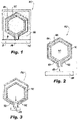
- FIG. 2 shows the system 100 after powder removal and separation from the build platform 108.
- the method includes shifting the fluid conduit 102 and fluid nozzle 124 to a shifted position (shown in Fig. 3 ,) relative to the heat shield 104, and securing the fluid conduit 102 and fluid nozzle 124 to the heat shield 104 in the shifted position e.g. by welding, bolting, or brazing to a member 104 or the like.
- Fig. 3 shows the system 100 after powder removal and separation from the build platform 108.
- the method includes shifting the fluid conduit 102 and fluid nozzle 124 to a shifted position (shown in Fig. 3 ,) relative to the heat shield 104, and securing the fluid conduit 102 and fluid nozzle 124 to the heat shield 104 in the shifted position e.g. by welding, bolting, or brazing to a member 104 or the like.
- each of the fluid conduit 102 and heat shield 104 can be aligned along a direction A that exceeds the maximum build angle of the additive manufacturing process, which can even be, for example perpendicular to the build direction B.
- forming the fluid nozzle 124 can include forming the fluid nozzle 124 as an annular terminus 125 at the downstream end of the fluid conduit 102, wherein the annular terminus 125 defines an annular fluid gallery 126 in fluid communication with a flow channel (interior passage 110) through the fluid conduit 102.
- the heat shield 104 can include an inner heat shield portion 128 radially inside the annular terminus 125.
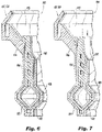
- the inner heat shield portion 128 and the annular terminus 125 define an inner shield sealing gap 130 therebetween. Shifting the fluid conduit 102 and fluid nozzle 124 (as shown in Figs. 2-3 ) includes reducing axial extent of the inner heat shield sealing gap 104, as shown in Fig. 6 , which shows the system 100 before shifting, and in Fig. 7 , which shows the system 100 in the shifted position.
- the inner heat shield portion 128 can define an inner air swirler 132 radially inward of the fluid nozzle 124.
- the heat shield 104 can include an outer heat shield portion 134 radially outside the annular terminus 125.
- the outer heat shield portion 134 and the annular terminus 125 define an outer shield sealing gap 136 therebetween. Shifting the fluid conduit 102 and fluid nozzle 124 includes reducing axial extent of the outer heat shield gap 136 similar to how it is described above with respect to the sealing gap 130.
- the outer heat shield portion 134 can define an outer air passage 138 radially outward of the fluid nozzle 124.
- forming the fluid conduit 102, fluid nozzle 124, and heat shield 104 can include forming a series of supports 118 along a spine 116 of the heat shield 104 and the fluid conduit 102 between the build platform 108 and the fluid conduit 102, as well as between the build platform 108 and the fluid nozzle 124.
- Forming the series of supports 118 can include forming a series of apertures 120 through the heat shield 104, as shown in Fig. 9 .
- Each support 118, whether extending from the nozzle 124 or from the fluid conduit 102, extends through a respective one of the apertures 120.
- the supports 118 can extend through the apertures 120 during the build process to support the fluid conduit 102 and the fluid nozzle 124 on the build platform 108, as shown in Fig. 8 , during the build. Shifting the fluid conduit 102 and the fluid nozzle 124 to the shifted position (e.g. shown in Fig. 3 ) can include shifting the supports 118 through the respective apertures 120 until the supports 118 extend externally from the heat shield 104, as shown in Fig. 3 . Shifting the supports 118 can include shifting the supports 118 until spacer features, including seals 122 in Fig. 2 and seals 140 in Fig. 9 engage, spacing the heat shield 104 from the fluid conduit 102 to maintain the insulative gap 112 (identified in Figs.
- At least some of the apertures 120 through the heat shield 104 can be elongated (as are the apertures 142 in Fig. 10 ) to accommodate relative thermal expansion/contraction between the fluid conduit 102 and the heat shield 104.
- Securing the fluid conduit 102 and the fluid nozzle 124 to the heat shield 104 as indicated in Fig. 3 can include welding, bolting and/or brazing the supports 118 to the heat shield 104.
- the supports 118 can extend outside the heat shield 104 as shown in Fig. 3 , or can be trimmed, e.g. to be flush with the outside of the heat shield 104.
- Securing the fluid conduit 102 can also include welding, bolting, and/or brazing a flange 146 defined at an upstream end of the fluid conduit 102 to a flange 144 defined at an upstream end of the heat shield 104, e.g., wherein the upstream ends are opposite the downstream ends where the nozzle 124 is located.
Landscapes
- Engineering & Computer Science (AREA)
- Chemical & Material Sciences (AREA)
- Manufacturing & Machinery (AREA)
- Materials Engineering (AREA)
- Mechanical Engineering (AREA)
- Combustion & Propulsion (AREA)
- General Engineering & Computer Science (AREA)
- Powder Metallurgy (AREA)
- Turbine Rotor Nozzle Sealing (AREA)
Abstract
Description
- The present disclosure relates to fluid nozzles, and more particularly to fluid nozzles such as used in injectors for gas turbine engines.
- Fluid nozzles such as used for fuel need to be insulated from heat, e.g. in gas turbine engines. It is desirable to make fluid passages using additive manufacturing. However, the internal fluid passage must be supported during an additive process, and the supports thermally connect the conduit to the heat shield. This thermal connection undermines the heat shielding.
- The conventional techniques have been considered satisfactory for their intended purpose. However, there is an ever present need for improved systems and methods for fluid conduits. This disclosure provides a solution for this need.
- A system includes a fluid conduit and a fluid nozzle each within a heat shield. The fluid conduit and the fluid nozzle each include a series of supports extending therefrom. The heat shield includes a series of apertures therethrough. Each support in the series of supports extends through a respective one of the apertures in the series of apertures.
- At least some of the apertures through the heat shield can be elongated to accommodate relative thermal expansion/contraction between the fluid conduit and the heat shield. The fluid nozzle can form an annular terminus at a downstream end of the fluid conduit, wherein the annular terminus defines an annular fluid gallery in fluid communication with a flow channel through the fluid conduit. The heat shield can include an inner heat shield portion radially inside the annular terminus, wherein the inner heat shield portion and the annular terminus define an inner shield gap therebetween. The inner heat shield portion can define an inner air swirler radially inward of the fluid nozzle. The heat shield can include an outer heat shield portion radially outside the annular terminus, wherein the outer heat shield portion and the annular terminus define an outer shield gap therebetween. The outer heat shield portion can define an outer air passage radially outward of the fluid nozzle.
- These and other features of the systems and methods of the subject disclosure will become more readily apparent to those skilled in the art from the following detailed description of the preferred embodiments taken in conjunction with the drawings.
- So that those skilled in the art to which the subject disclosure appertains will readily understand how to make and use the devices and methods of the subject disclosure without undue experimentation, preferred embodiments thereof will be described in detail herein below with reference to certain figures, wherein:
-
Fig. 1 is a schematic axial elevation view of an embodiment of a system constructed in accordance with the present disclosure, showing the heat shield and fluid conduit during additive manufacturing; -
Fig. 2 is a schematic axial elevation view of the system ofFig. 1 , showing the system after removal of unfused powder; -
Fig. 3 is a schematic axial elevation view of the system ofFig. 1 , showing the system after shifting the heat shield and fluid conduit relative to one another; -
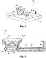
Fig. 4 is a perspective view of the system ofFig. 1 , showing the fluid nozzle; -
Fig. 5 is a cross-sectional side elevation view of the system ofFig. 1 , showing the annular gallery of the fluid nozzle; -
Figs. 6 and 7 are cross-sectional side elevation views of the system ofFig. 1 , showing the system before and after shifting the fluid conduit and fluid nozzle into the shifted position, respectively; -
Fig. 8 is a perspective view of a portion of the system ofFig. 1 , with the heat shield removed to show thesupports 118 supporting the fluid conduit and fluid nozzle on the build platform or plate; -
Fig. 9 is a cross-sectional perspective view of portion of the system ofFig. 1 , showing the supports extending through apertures in the heat shield; and -
Fig. 10 is a perspective view of a portion of the system ofFig. 1 , showing elongated apertures through the heat shield to accommodate relative thermal expansion of the heat shield and fluid conduit. - Reference will now be made to the drawings wherein like reference numerals identify similar structural features or aspects of the subject disclosure. For purposes of explanation and illustration, and not limitation, a partial view of an embodiment of a system in accordance with the disclosure is shown in
Fig. 1 and is designated generally byreference character 100. Other embodiments of systems in accordance with the disclosure, or aspects thereof, are provided inFigs. 2-10 , as will be described. The systems and methods described herein can be used to additively manufacture fluid conduits and nozzles with heat shielding, e.g. for fuel injection in gas turbine engines and the like. - A method includes forming a
fluid conduit 102 inside aheat shield 104 in an additive manufacturing process, wherein a fluid nozzle 124 (shown inFig. 4 ) is defined at a downstream end of thefluid conduit 102. Theheat shield 104 is formed about the fluid nozzle 124 (shown inFig. 4 ). The method includes removing powder 106, e.g. unfused additive manufacturing stock powder, from aninterior passage 110 of thefluid conduit 102 andfluid nozzle 124. The method also includes removing the powder 106 from aninsulation gap 112 defined between theheat shield 104 and thefluid conduit 102 andfluid nozzle 124. The method includes separating theheat shield 104, thefluid conduit 102, and thefluid nozzle 124 from thebuild platform 108.Fig. 2 shows thesystem 100 after powder removal and separation from thebuild platform 108. The method includes shifting thefluid conduit 102 andfluid nozzle 124 to a shifted position (shown inFig. 3 ,) relative to theheat shield 104, and securing thefluid conduit 102 andfluid nozzle 124 to theheat shield 104 in the shifted position e.g. by welding, bolting, or brazing to amember 104 or the like. With reference toFig. 4 , during forming thefluid conduit 102 andfluid nozzle 124 inside theheat shield 104, at least a portion of each of thefluid conduit 102 andheat shield 104 can be aligned along a direction A that exceeds the maximum build angle of the additive manufacturing process, which can even be, for example perpendicular to the build direction B. - With reference now to
Fig. 5 , forming thefluid nozzle 124 can include forming thefluid nozzle 124 as an annular terminus 125 at the downstream end of thefluid conduit 102, wherein the annular terminus 125 defines anannular fluid gallery 126 in fluid communication with a flow channel (interior passage 110) through thefluid conduit 102. Theheat shield 104 can include an innerheat shield portion 128 radially inside the annular terminus 125. - With reference now to
Figs. 6-7 , the innerheat shield portion 128 and the annular terminus 125 define an innershield sealing gap 130 therebetween. Shifting thefluid conduit 102 and fluid nozzle 124 (as shown inFigs. 2-3 ) includes reducing axial extent of the inner heatshield sealing gap 104, as shown inFig. 6 , which shows thesystem 100 before shifting, and inFig. 7 , which shows thesystem 100 in the shifted position. The innerheat shield portion 128 can define aninner air swirler 132 radially inward of thefluid nozzle 124. Theheat shield 104 can include an outerheat shield portion 134 radially outside the annular terminus 125. The outerheat shield portion 134 and the annular terminus 125 define an outershield sealing gap 136 therebetween. Shifting thefluid conduit 102 andfluid nozzle 124 includes reducing axial extent of the outerheat shield gap 136 similar to how it is described above with respect to thesealing gap 130. The outerheat shield portion 134 can define anouter air passage 138 radially outward of thefluid nozzle 124. - With reference now to
Fig. 8 (which shows thesystem 100 with theheat shield 104 removed), forming thefluid conduit 102,fluid nozzle 124, andheat shield 104 can include forming a series ofsupports 118 along aspine 116 of theheat shield 104 and thefluid conduit 102 between thebuild platform 108 and thefluid conduit 102, as well as between thebuild platform 108 and thefluid nozzle 124. Forming the series ofsupports 118 can include forming a series ofapertures 120 through theheat shield 104, as shown inFig. 9 . Eachsupport 118, whether extending from thenozzle 124 or from thefluid conduit 102, extends through a respective one of theapertures 120. Thesupports 118 can extend through theapertures 120 during the build process to support thefluid conduit 102 and thefluid nozzle 124 on thebuild platform 108, as shown inFig. 8 , during the build. Shifting thefluid conduit 102 and thefluid nozzle 124 to the shifted position (e.g. shown inFig. 3 ) can include shifting thesupports 118 through therespective apertures 120 until thesupports 118 extend externally from theheat shield 104, as shown inFig. 3 . Shifting thesupports 118 can include shifting thesupports 118 until spacer features, includingseals 122 inFig. 2 andseals 140 inFig. 9 engage, spacing theheat shield 104 from thefluid conduit 102 to maintain the insulative gap 112 (identified inFigs. 3 ), and to help seal stagnant air inside theinsulative gap 112. At least some of theapertures 120 through theheat shield 104 can be elongated (as are theapertures 142 inFig. 10 ) to accommodate relative thermal expansion/contraction between thefluid conduit 102 and theheat shield 104. - Securing the
fluid conduit 102 and thefluid nozzle 124 to theheat shield 104 as indicated inFig. 3 can include welding, bolting and/or brazing thesupports 118 to theheat shield 104. Thesupports 118 can extend outside theheat shield 104 as shown inFig. 3 , or can be trimmed, e.g. to be flush with the outside of theheat shield 104. Securing thefluid conduit 102 can also include welding, bolting, and/or brazing aflange 146 defined at an upstream end of thefluid conduit 102 to aflange 144 defined at an upstream end of theheat shield 104, e.g., wherein the upstream ends are opposite the downstream ends where thenozzle 124 is located. - The methods and systems of the present disclosure, as described above and shown in the drawings, provide for additive manufacture of fluid conduits and fluid nozzles with heat shielding. While the apparatus and methods of the subject disclosure have been shown and described with reference to preferred embodiments, those skilled in the art will readily appreciate that changes and/or modifications may be made thereto without departing from the scope of the subject disclosure.
Claims (5)
- A system comprising:a fluid conduit (102) having a plurality of conduit supports;a fluid nozzle (124) having a plurality of nozzle supports, the fluid nozzle being connected to the fluid conduit; anda heat shield (104) having a plurality of apertures, the heat shield surrounding both the fluid conduit and the fluid nozzle such that the conduit supports and the nozzle supports extend through the apertures.
- The system as recited in claim 1, further comprising a build platform attached to the conduit supports and to the nozzle supports.
- The system as recited in claim 1 or 2, wherein at least some of the apertures through the heat shield are elongated to accommodate relative thermal expansion/contraction between the fluid conduit and the heat shield.
- The system of claim 3 wherein the fluid nozzle forms an annular terminus at a downstream end of the fluid conduit, wherein the annular terminus defines an annular fluid gallery in fluid communication with a flow channel through the fluid conduit.
- The system of claim 4 wherein the heat shield includes an inner heat shield portion radially inside the annular terminus, wherein the inner heat shield portion and the annular terminus define an inner shield gap therebetween.
Applications Claiming Priority (2)
| Application Number | Priority Date | Filing Date | Title |
|---|---|---|---|
| US16/593,732 US11117155B2 (en) | 2019-10-04 | 2019-10-04 | Fluid nozzles with heat shielding |
| EP19214578.7A EP3800400B1 (en) | 2019-10-04 | 2019-12-09 | Method for forming a fluid conduit |
Related Parent Applications (2)
| Application Number | Title | Priority Date | Filing Date |
|---|---|---|---|
| EP19214578.7A Division-Into EP3800400B1 (en) | 2019-10-04 | 2019-12-09 | Method for forming a fluid conduit |
| EP19214578.7A Division EP3800400B1 (en) | 2019-10-04 | 2019-12-09 | Method for forming a fluid conduit |
Publications (2)
| Publication Number | Publication Date |
|---|---|
| EP3978806A1 true EP3978806A1 (en) | 2022-04-06 |
| EP3978806B1 EP3978806B1 (en) | 2023-11-29 |
Family
ID=68840989
Family Applications (2)
| Application Number | Title | Priority Date | Filing Date |
|---|---|---|---|
| EP21209647.3A Active EP3978806B1 (en) | 2019-10-04 | 2019-12-09 | Fluid nozzles with heat shielding |
| EP19214578.7A Active EP3800400B1 (en) | 2019-10-04 | 2019-12-09 | Method for forming a fluid conduit |
Family Applications After (1)
| Application Number | Title | Priority Date | Filing Date |
|---|---|---|---|
| EP19214578.7A Active EP3800400B1 (en) | 2019-10-04 | 2019-12-09 | Method for forming a fluid conduit |
Country Status (2)
| Country | Link |
|---|---|
| US (2) | US11117155B2 (en) |
| EP (2) | EP3978806B1 (en) |
Cited By (2)
| Publication number | Priority date | Publication date | Assignee | Title |
|---|---|---|---|---|
| DE102022208337A1 (en) * | 2022-08-10 | 2024-02-15 | Rolls-Royce Deutschland Ltd & Co Kg | Piloting arrangement, nozzle device, method and gas turbine arrangement |
| DE102023203942A1 (en) * | 2023-04-27 | 2024-10-31 | Rolls-Royce Deutschland Ltd & Co Kg | PILOTING ARRANGEMENT FOR A NOZZLE DEVICE AND NOZZLE DEVICE AND GAS TURBINE ARRANGEMENT WITH A PILOTING ARRANGEMENT |
Families Citing this family (2)
| Publication number | Priority date | Publication date | Assignee | Title |
|---|---|---|---|---|
| US11369985B2 (en) * | 2019-10-04 | 2022-06-28 | Delavan Inc | Fluid conduits with heat shielding |
| DE102023201244A1 (en) * | 2023-02-14 | 2024-08-14 | Rolls-Royce Deutschland Ltd & Co Kg | PILOTING ARRANGEMENT, NOZZLE DEVICE, GAS TURBINE ARRANGEMENT AND METHOD |
Citations (4)
| Publication number | Priority date | Publication date | Assignee | Title |
|---|---|---|---|---|
| US20030141388A1 (en) * | 2000-06-28 | 2003-07-31 | Johnson Arthur Wesley | Methods and apparatus for decreasing combustor emissions |
| US20150354517A1 (en) * | 2013-01-02 | 2015-12-10 | Parker-Hannifin Corporation | Direct injection multipoint nozzle |
| US20160236271A1 (en) * | 2013-10-04 | 2016-08-18 | United Technologies Corporation | Additive manufactured fuel nozzle core for a gas turbine engine |
| EP3770401A1 (en) * | 2019-07-22 | 2021-01-27 | Delavan, Inc. | Fuel manifolds |
Family Cites Families (21)
| Publication number | Priority date | Publication date | Assignee | Title |
|---|---|---|---|---|
| FR1186524A (en) | 1956-11-19 | 1959-08-26 | Havilland Engine Co Ltd | Fuel injection devices for gas turbines |
| US20090255120A1 (en) * | 2008-04-11 | 2009-10-15 | General Electric Company | Method of assembling a fuel nozzle |
| US8806871B2 (en) * | 2008-04-11 | 2014-08-19 | General Electric Company | Fuel nozzle |
| US9400104B2 (en) * | 2012-09-28 | 2016-07-26 | United Technologies Corporation | Flow modifier for combustor fuel nozzle tip |
| US20140291418A1 (en) * | 2013-03-26 | 2014-10-02 | Parker-Hannifin Corporation | Multi-circuit airblast fuel nozzle |
| US9556795B2 (en) * | 2013-09-06 | 2017-01-31 | Delavan Inc | Integrated heat shield |
| US20160305712A1 (en) * | 2013-12-12 | 2016-10-20 | United Technologies Corporation | Heat-shielded conduit |
| US10488047B2 (en) * | 2014-01-24 | 2019-11-26 | United Technologies Corporation | Thermally compliant additively manufactured fuel injector |
| US9915480B2 (en) | 2014-07-03 | 2018-03-13 | United Technologies Corporation | Tube assembly |
| US9759356B2 (en) | 2014-07-03 | 2017-09-12 | United Technologies Corporation | Insulated flowpath assembly |
| US20160003157A1 (en) | 2014-07-03 | 2016-01-07 | United Technologies Corporation | Additive manufactured tube assembly |
| US10071704B2 (en) | 2014-07-25 | 2018-09-11 | Hyundai Mobis Co., Ltd. | Apparatus and method for folding driver airbag |
| US9791153B2 (en) * | 2015-02-27 | 2017-10-17 | United Technologies Corporation | Line replaceable fuel nozzle apparatus, system and method |
| US10329950B2 (en) * | 2015-03-23 | 2019-06-25 | Rolls-Royce North American Technologies Inc. | Nozzle guide vane with composite heat shield |
| US10378446B2 (en) * | 2015-11-17 | 2019-08-13 | Delavan Inc | Thermal management for injectors |
| US20170211480A1 (en) * | 2016-01-21 | 2017-07-27 | Delavan Inc | Discrete jet orifices |
| US20180163635A1 (en) * | 2016-12-13 | 2018-06-14 | Delavan Inc | Fluid valves |
| DE102017200643A1 (en) | 2017-01-17 | 2018-07-19 | Siemens Aktiengesellschaft | A burner tip having an air channel structure and a fuel channel structure for a burner and method of making the burner tip |
| US11208956B2 (en) | 2017-10-20 | 2021-12-28 | Delavan Inc. | Fuel injectors and methods of making fuel injectors |
| CN109339951A (en) | 2018-10-22 | 2019-02-15 | 北京工业大学 | An additive manufacturing structure for the heat shield of the oil supply oil circuit of the hot end part of the aero-engine |
| US11933226B2 (en) * | 2022-05-13 | 2024-03-19 | Rtx Corporation | Heat shield and method of installing the same |
-
2019
- 2019-10-04 US US16/593,732 patent/US11117155B2/en active Active
- 2019-12-09 EP EP21209647.3A patent/EP3978806B1/en active Active
- 2019-12-09 EP EP19214578.7A patent/EP3800400B1/en active Active
-
2021
- 2021-08-17 US US17/404,651 patent/US11994297B2/en active Active
Patent Citations (4)
| Publication number | Priority date | Publication date | Assignee | Title |
|---|---|---|---|---|
| US20030141388A1 (en) * | 2000-06-28 | 2003-07-31 | Johnson Arthur Wesley | Methods and apparatus for decreasing combustor emissions |
| US20150354517A1 (en) * | 2013-01-02 | 2015-12-10 | Parker-Hannifin Corporation | Direct injection multipoint nozzle |
| US20160236271A1 (en) * | 2013-10-04 | 2016-08-18 | United Technologies Corporation | Additive manufactured fuel nozzle core for a gas turbine engine |
| EP3770401A1 (en) * | 2019-07-22 | 2021-01-27 | Delavan, Inc. | Fuel manifolds |
Cited By (3)
| Publication number | Priority date | Publication date | Assignee | Title |
|---|---|---|---|---|
| DE102022208337A1 (en) * | 2022-08-10 | 2024-02-15 | Rolls-Royce Deutschland Ltd & Co Kg | Piloting arrangement, nozzle device, method and gas turbine arrangement |
| US12007118B2 (en) | 2022-08-10 | 2024-06-11 | Rolls-Royce Deutschland Ltd & Co Kg | Pilot arrangement, nozzle device, method and gas turbine arrangement |
| DE102023203942A1 (en) * | 2023-04-27 | 2024-10-31 | Rolls-Royce Deutschland Ltd & Co Kg | PILOTING ARRANGEMENT FOR A NOZZLE DEVICE AND NOZZLE DEVICE AND GAS TURBINE ARRANGEMENT WITH A PILOTING ARRANGEMENT |
Also Published As
| Publication number | Publication date |
|---|---|
| US11117155B2 (en) | 2021-09-14 |
| US11994297B2 (en) | 2024-05-28 |
| EP3800400A1 (en) | 2021-04-07 |
| EP3800400B1 (en) | 2023-05-10 |
| US20210370334A1 (en) | 2021-12-02 |
| EP3978806B1 (en) | 2023-11-29 |
| US20210101169A1 (en) | 2021-04-08 |
Similar Documents
| Publication | Publication Date | Title |
|---|---|---|
| US11994297B2 (en) | Fluid nozzles with heat shielding | |
| US11692487B2 (en) | Heat shielding for internal fuel manifolds | |
| US7992390B2 (en) | External rigid fuel manifold | |
| EP2902605B1 (en) | A fuel manifold and fuel injector arrangement for a gas turbine engine | |
| EP3109548A1 (en) | Combustion system with combustor dome integrated fuel manifold | |
| EP2413037A2 (en) | Flexure seal for fuel injection nozzle | |
| EP3643969B1 (en) | Multipoint injection system for a gas turbine combustor | |
| EP3090138B1 (en) | Heat shields for air seals | |
| US11674687B2 (en) | Fuel manifolds | |
| US11713717B2 (en) | Sectional fuel manifolds | |
| CN107869392A (en) | Mounting assembly for gas-turbine unit fluid circuit | |
| US12269053B2 (en) | Fluid conduits with heat shielding | |
| EP4417874B1 (en) | Line replaceable fuel injector panels with single hatch installation | |
| EP3809044B1 (en) | Gasturbine engine with a fuel manifold | |
| EP4417875B1 (en) | System with replaceable fuel injector panels for a gas turbine engine |
Legal Events
| Date | Code | Title | Description |
|---|---|---|---|
| PUAI | Public reference made under article 153(3) epc to a published international application that has entered the european phase |
Free format text: ORIGINAL CODE: 0009012 |
|
| STAA | Information on the status of an ep patent application or granted ep patent |
Free format text: STATUS: THE APPLICATION HAS BEEN PUBLISHED |
|
| AC | Divisional application: reference to earlier application |
Ref document number: 3800400 Country of ref document: EP Kind code of ref document: P |
|
| AK | Designated contracting states |
Kind code of ref document: A1 Designated state(s): AL AT BE BG CH CY CZ DE DK EE ES FI FR GB GR HR HU IE IS IT LI LT LU LV MC MK MT NL NO PL PT RO RS SE SI SK SM TR |
|
| RAP3 | Party data changed (applicant data changed or rights of an application transferred) |
Owner name: COLLINS ENGINE NOZZLES, INC. |
|
| STAA | Information on the status of an ep patent application or granted ep patent |
Free format text: STATUS: REQUEST FOR EXAMINATION WAS MADE |
|
| 17P | Request for examination filed |
Effective date: 20221005 |
|
| RBV | Designated contracting states (corrected) |
Designated state(s): AL AT BE BG CH CY CZ DE DK EE ES FI FR GB GR HR HU IE IS IT LI LT LU LV MC MK MT NL NO PL PT RO RS SE SI SK SM TR |
|
| GRAP | Despatch of communication of intention to grant a patent |
Free format text: ORIGINAL CODE: EPIDOSNIGR1 |
|
| STAA | Information on the status of an ep patent application or granted ep patent |
Free format text: STATUS: GRANT OF PATENT IS INTENDED |
|
| INTG | Intention to grant announced |
Effective date: 20230615 |
|
| GRAS | Grant fee paid |
Free format text: ORIGINAL CODE: EPIDOSNIGR3 |
|
| GRAA | (expected) grant |
Free format text: ORIGINAL CODE: 0009210 |
|
| STAA | Information on the status of an ep patent application or granted ep patent |
Free format text: STATUS: THE PATENT HAS BEEN GRANTED |
|
| P01 | Opt-out of the competence of the unified patent court (upc) registered |
Effective date: 20230922 |
|
| AC | Divisional application: reference to earlier application |
Ref document number: 3800400 Country of ref document: EP Kind code of ref document: P |
|
| AK | Designated contracting states |
Kind code of ref document: B1 Designated state(s): AL AT BE BG CH CY CZ DE DK EE ES FI FR GB GR HR HU IE IS IT LI LT LU LV MC MK MT NL NO PL PT RO RS SE SI SK SM TR |
|
| REG | Reference to a national code |
Ref country code: GB Ref legal event code: FG4D |
|
| REG | Reference to a national code |
Ref country code: CH Ref legal event code: EP |
|
| REG | Reference to a national code |
Ref country code: DE Ref legal event code: R096 Ref document number: 602019042645 Country of ref document: DE |
|
| REG | Reference to a national code |
Ref country code: IE Ref legal event code: FG4D |
|
| REG | Reference to a national code |
Ref country code: LT Ref legal event code: MG9D |
|
| REG | Reference to a national code |
Ref country code: NL Ref legal event code: MP Effective date: 20231129 |
|
| PG25 | Lapsed in a contracting state [announced via postgrant information from national office to epo] |
Ref country code: GR Free format text: LAPSE BECAUSE OF FAILURE TO SUBMIT A TRANSLATION OF THE DESCRIPTION OR TO PAY THE FEE WITHIN THE PRESCRIBED TIME-LIMIT Effective date: 20240301 |
|
| PG25 | Lapsed in a contracting state [announced via postgrant information from national office to epo] |
Ref country code: IS Free format text: LAPSE BECAUSE OF FAILURE TO SUBMIT A TRANSLATION OF THE DESCRIPTION OR TO PAY THE FEE WITHIN THE PRESCRIBED TIME-LIMIT Effective date: 20240329 |
|
| PG25 | Lapsed in a contracting state [announced via postgrant information from national office to epo] |
Ref country code: LT Free format text: LAPSE BECAUSE OF FAILURE TO SUBMIT A TRANSLATION OF THE DESCRIPTION OR TO PAY THE FEE WITHIN THE PRESCRIBED TIME-LIMIT Effective date: 20231129 |
|
| PG25 | Lapsed in a contracting state [announced via postgrant information from national office to epo] |
Ref country code: ES Free format text: LAPSE BECAUSE OF FAILURE TO SUBMIT A TRANSLATION OF THE DESCRIPTION OR TO PAY THE FEE WITHIN THE PRESCRIBED TIME-LIMIT Effective date: 20231129 |
|
| PG25 | Lapsed in a contracting state [announced via postgrant information from national office to epo] |
Ref country code: LT Free format text: LAPSE BECAUSE OF FAILURE TO SUBMIT A TRANSLATION OF THE DESCRIPTION OR TO PAY THE FEE WITHIN THE PRESCRIBED TIME-LIMIT Effective date: 20231129 Ref country code: IS Free format text: LAPSE BECAUSE OF FAILURE TO SUBMIT A TRANSLATION OF THE DESCRIPTION OR TO PAY THE FEE WITHIN THE PRESCRIBED TIME-LIMIT Effective date: 20240329 Ref country code: GR Free format text: LAPSE BECAUSE OF FAILURE TO SUBMIT A TRANSLATION OF THE DESCRIPTION OR TO PAY THE FEE WITHIN THE PRESCRIBED TIME-LIMIT Effective date: 20240301 Ref country code: ES Free format text: LAPSE BECAUSE OF FAILURE TO SUBMIT A TRANSLATION OF THE DESCRIPTION OR TO PAY THE FEE WITHIN THE PRESCRIBED TIME-LIMIT Effective date: 20231129 Ref country code: BG Free format text: LAPSE BECAUSE OF FAILURE TO SUBMIT A TRANSLATION OF THE DESCRIPTION OR TO PAY THE FEE WITHIN THE PRESCRIBED TIME-LIMIT Effective date: 20240229 |
|
| REG | Reference to a national code |
Ref country code: AT Ref legal event code: MK05 Ref document number: 1636487 Country of ref document: AT Kind code of ref document: T Effective date: 20231129 |
|
| PG25 | Lapsed in a contracting state [announced via postgrant information from national office to epo] |
Ref country code: NL Free format text: LAPSE BECAUSE OF FAILURE TO SUBMIT A TRANSLATION OF THE DESCRIPTION OR TO PAY THE FEE WITHIN THE PRESCRIBED TIME-LIMIT Effective date: 20231129 |
|
| PG25 | Lapsed in a contracting state [announced via postgrant information from national office to epo] |
Ref country code: SE Free format text: LAPSE BECAUSE OF FAILURE TO SUBMIT A TRANSLATION OF THE DESCRIPTION OR TO PAY THE FEE WITHIN THE PRESCRIBED TIME-LIMIT Effective date: 20231129 Ref country code: RS Free format text: LAPSE BECAUSE OF FAILURE TO SUBMIT A TRANSLATION OF THE DESCRIPTION OR TO PAY THE FEE WITHIN THE PRESCRIBED TIME-LIMIT Effective date: 20231129 Ref country code: PL Free format text: LAPSE BECAUSE OF FAILURE TO SUBMIT A TRANSLATION OF THE DESCRIPTION OR TO PAY THE FEE WITHIN THE PRESCRIBED TIME-LIMIT Effective date: 20231129 Ref country code: NO Free format text: LAPSE BECAUSE OF FAILURE TO SUBMIT A TRANSLATION OF THE DESCRIPTION OR TO PAY THE FEE WITHIN THE PRESCRIBED TIME-LIMIT Effective date: 20240229 Ref country code: NL Free format text: LAPSE BECAUSE OF FAILURE TO SUBMIT A TRANSLATION OF THE DESCRIPTION OR TO PAY THE FEE WITHIN THE PRESCRIBED TIME-LIMIT Effective date: 20231129 Ref country code: LV Free format text: LAPSE BECAUSE OF FAILURE TO SUBMIT A TRANSLATION OF THE DESCRIPTION OR TO PAY THE FEE WITHIN THE PRESCRIBED TIME-LIMIT Effective date: 20231129 Ref country code: HR Free format text: LAPSE BECAUSE OF FAILURE TO SUBMIT A TRANSLATION OF THE DESCRIPTION OR TO PAY THE FEE WITHIN THE PRESCRIBED TIME-LIMIT Effective date: 20231129 |
|
| PG25 | Lapsed in a contracting state [announced via postgrant information from national office to epo] |
Ref country code: DK Free format text: LAPSE BECAUSE OF FAILURE TO SUBMIT A TRANSLATION OF THE DESCRIPTION OR TO PAY THE FEE WITHIN THE PRESCRIBED TIME-LIMIT Effective date: 20231129 |
|
| PG25 | Lapsed in a contracting state [announced via postgrant information from national office to epo] |
Ref country code: CZ Free format text: LAPSE BECAUSE OF FAILURE TO SUBMIT A TRANSLATION OF THE DESCRIPTION OR TO PAY THE FEE WITHIN THE PRESCRIBED TIME-LIMIT Effective date: 20231129 Ref country code: AT Free format text: LAPSE BECAUSE OF FAILURE TO SUBMIT A TRANSLATION OF THE DESCRIPTION OR TO PAY THE FEE WITHIN THE PRESCRIBED TIME-LIMIT Effective date: 20231129 |
|
| PG25 | Lapsed in a contracting state [announced via postgrant information from national office to epo] |
Ref country code: SK Free format text: LAPSE BECAUSE OF FAILURE TO SUBMIT A TRANSLATION OF THE DESCRIPTION OR TO PAY THE FEE WITHIN THE PRESCRIBED TIME-LIMIT Effective date: 20231129 |
|
| PG25 | Lapsed in a contracting state [announced via postgrant information from national office to epo] |
Ref country code: SM Free format text: LAPSE BECAUSE OF FAILURE TO SUBMIT A TRANSLATION OF THE DESCRIPTION OR TO PAY THE FEE WITHIN THE PRESCRIBED TIME-LIMIT Effective date: 20231129 Ref country code: SK Free format text: LAPSE BECAUSE OF FAILURE TO SUBMIT A TRANSLATION OF THE DESCRIPTION OR TO PAY THE FEE WITHIN THE PRESCRIBED TIME-LIMIT Effective date: 20231129 Ref country code: RO Free format text: LAPSE BECAUSE OF FAILURE TO SUBMIT A TRANSLATION OF THE DESCRIPTION OR TO PAY THE FEE WITHIN THE PRESCRIBED TIME-LIMIT Effective date: 20231129 Ref country code: IT Free format text: LAPSE BECAUSE OF FAILURE TO SUBMIT A TRANSLATION OF THE DESCRIPTION OR TO PAY THE FEE WITHIN THE PRESCRIBED TIME-LIMIT Effective date: 20231129 Ref country code: EE Free format text: LAPSE BECAUSE OF FAILURE TO SUBMIT A TRANSLATION OF THE DESCRIPTION OR TO PAY THE FEE WITHIN THE PRESCRIBED TIME-LIMIT Effective date: 20231129 Ref country code: DK Free format text: LAPSE BECAUSE OF FAILURE TO SUBMIT A TRANSLATION OF THE DESCRIPTION OR TO PAY THE FEE WITHIN THE PRESCRIBED TIME-LIMIT Effective date: 20231129 Ref country code: CZ Free format text: LAPSE BECAUSE OF FAILURE TO SUBMIT A TRANSLATION OF THE DESCRIPTION OR TO PAY THE FEE WITHIN THE PRESCRIBED TIME-LIMIT Effective date: 20231129 Ref country code: AT Free format text: LAPSE BECAUSE OF FAILURE TO SUBMIT A TRANSLATION OF THE DESCRIPTION OR TO PAY THE FEE WITHIN THE PRESCRIBED TIME-LIMIT Effective date: 20231129 |
|
| REG | Reference to a national code |
Ref country code: CH Ref legal event code: PL |
|
| PG25 | Lapsed in a contracting state [announced via postgrant information from national office to epo] |
Ref country code: PT Free format text: LAPSE BECAUSE OF FAILURE TO SUBMIT A TRANSLATION OF THE DESCRIPTION OR TO PAY THE FEE WITHIN THE PRESCRIBED TIME-LIMIT Effective date: 20240401 |
|
| PG25 | Lapsed in a contracting state [announced via postgrant information from national office to epo] |
Ref country code: LU Free format text: LAPSE BECAUSE OF NON-PAYMENT OF DUE FEES Effective date: 20231209 |
|
| PG25 | Lapsed in a contracting state [announced via postgrant information from national office to epo] |
Ref country code: MC Free format text: LAPSE BECAUSE OF FAILURE TO SUBMIT A TRANSLATION OF THE DESCRIPTION OR TO PAY THE FEE WITHIN THE PRESCRIBED TIME-LIMIT Effective date: 20231129 |
|
| REG | Reference to a national code |
Ref country code: BE Ref legal event code: MM Effective date: 20231231 |
|
| PG25 | Lapsed in a contracting state [announced via postgrant information from national office to epo] |
Ref country code: PT Free format text: LAPSE BECAUSE OF FAILURE TO SUBMIT A TRANSLATION OF THE DESCRIPTION OR TO PAY THE FEE WITHIN THE PRESCRIBED TIME-LIMIT Effective date: 20240401 Ref country code: MC Free format text: LAPSE BECAUSE OF FAILURE TO SUBMIT A TRANSLATION OF THE DESCRIPTION OR TO PAY THE FEE WITHIN THE PRESCRIBED TIME-LIMIT Effective date: 20231129 Ref country code: LU Free format text: LAPSE BECAUSE OF NON-PAYMENT OF DUE FEES Effective date: 20231209 |
|
| REG | Reference to a national code |
Ref country code: DE Ref legal event code: R097 Ref document number: 602019042645 Country of ref document: DE |
|
| PLBE | No opposition filed within time limit |
Free format text: ORIGINAL CODE: 0009261 |
|
| STAA | Information on the status of an ep patent application or granted ep patent |
Free format text: STATUS: NO OPPOSITION FILED WITHIN TIME LIMIT |
|
| REG | Reference to a national code |
Ref country code: IE Ref legal event code: MM4A |
|
| PG25 | Lapsed in a contracting state [announced via postgrant information from national office to epo] |
Ref country code: IE Free format text: LAPSE BECAUSE OF NON-PAYMENT OF DUE FEES Effective date: 20231209 |
|
| PG25 | Lapsed in a contracting state [announced via postgrant information from national office to epo] |
Ref country code: BE Free format text: LAPSE BECAUSE OF NON-PAYMENT OF DUE FEES Effective date: 20231231 |
|
| PG25 | Lapsed in a contracting state [announced via postgrant information from national office to epo] |
Ref country code: CH Free format text: LAPSE BECAUSE OF NON-PAYMENT OF DUE FEES Effective date: 20231231 |
|
| PG25 | Lapsed in a contracting state [announced via postgrant information from national office to epo] |
Ref country code: SI Free format text: LAPSE BECAUSE OF FAILURE TO SUBMIT A TRANSLATION OF THE DESCRIPTION OR TO PAY THE FEE WITHIN THE PRESCRIBED TIME-LIMIT Effective date: 20231129 |
|
| PG25 | Lapsed in a contracting state [announced via postgrant information from national office to epo] |
Ref country code: SI Free format text: LAPSE BECAUSE OF FAILURE TO SUBMIT A TRANSLATION OF THE DESCRIPTION OR TO PAY THE FEE WITHIN THE PRESCRIBED TIME-LIMIT Effective date: 20231129 Ref country code: IE Free format text: LAPSE BECAUSE OF NON-PAYMENT OF DUE FEES Effective date: 20231209 Ref country code: CH Free format text: LAPSE BECAUSE OF NON-PAYMENT OF DUE FEES Effective date: 20231231 Ref country code: BE Free format text: LAPSE BECAUSE OF NON-PAYMENT OF DUE FEES Effective date: 20231231 |
|
| 26N | No opposition filed |
Effective date: 20240830 |
|
| PG25 | Lapsed in a contracting state [announced via postgrant information from national office to epo] |
Ref country code: FI Free format text: LAPSE BECAUSE OF FAILURE TO SUBMIT A TRANSLATION OF THE DESCRIPTION OR TO PAY THE FEE WITHIN THE PRESCRIBED TIME-LIMIT Effective date: 20231129 |
|
| PG25 | Lapsed in a contracting state [announced via postgrant information from national office to epo] |
Ref country code: CY Free format text: LAPSE BECAUSE OF FAILURE TO SUBMIT A TRANSLATION OF THE DESCRIPTION OR TO PAY THE FEE WITHIN THE PRESCRIBED TIME-LIMIT; INVALID AB INITIO Effective date: 20191209 |
|
| PG25 | Lapsed in a contracting state [announced via postgrant information from national office to epo] |
Ref country code: HU Free format text: LAPSE BECAUSE OF FAILURE TO SUBMIT A TRANSLATION OF THE DESCRIPTION OR TO PAY THE FEE WITHIN THE PRESCRIBED TIME-LIMIT; INVALID AB INITIO Effective date: 20191209 |
|
| PG25 | Lapsed in a contracting state [announced via postgrant information from national office to epo] |
Ref country code: TR Free format text: LAPSE BECAUSE OF FAILURE TO SUBMIT A TRANSLATION OF THE DESCRIPTION OR TO PAY THE FEE WITHIN THE PRESCRIBED TIME-LIMIT Effective date: 20231129 |
|
| PGFP | Annual fee paid to national office [announced via postgrant information from national office to epo] |
Ref country code: DE Payment date: 20251126 Year of fee payment: 7 |
|
| PGFP | Annual fee paid to national office [announced via postgrant information from national office to epo] |
Ref country code: GB Payment date: 20251119 Year of fee payment: 7 |
|
| PGFP | Annual fee paid to national office [announced via postgrant information from national office to epo] |
Ref country code: FR Payment date: 20251120 Year of fee payment: 7 |