EP3978777A1 - Brake pad of a vehicle brake, vehicle brake and method for assembling a vehicle brake - Google Patents
Brake pad of a vehicle brake, vehicle brake and method for assembling a vehicle brake Download PDFInfo
- Publication number
- EP3978777A1 EP3978777A1 EP20199137.9A EP20199137A EP3978777A1 EP 3978777 A1 EP3978777 A1 EP 3978777A1 EP 20199137 A EP20199137 A EP 20199137A EP 3978777 A1 EP3978777 A1 EP 3978777A1
- Authority
- EP
- European Patent Office
- Prior art keywords
- brake pad
- clamping member
- brake
- indication device
- recess
- Prior art date
- Legal status (The legal status is an assumption and is not a legal conclusion. Google has not performed a legal analysis and makes no representation as to the accuracy of the status listed.)
- Granted
Links
Images



Classifications
-
- F—MECHANICAL ENGINEERING; LIGHTING; HEATING; WEAPONS; BLASTING
- F16—ENGINEERING ELEMENTS AND UNITS; GENERAL MEASURES FOR PRODUCING AND MAINTAINING EFFECTIVE FUNCTIONING OF MACHINES OR INSTALLATIONS; THERMAL INSULATION IN GENERAL
- F16D—COUPLINGS FOR TRANSMITTING ROTATION; CLUTCHES; BRAKES
- F16D66/00—Arrangements for monitoring working conditions, e.g. wear, temperature
- F16D66/02—Apparatus for indicating wear
- F16D66/021—Apparatus for indicating wear using electrical detection or indication means
- F16D66/022—Apparatus for indicating wear using electrical detection or indication means indicating that a lining is worn to minimum allowable thickness
- F16D66/023—Apparatus for indicating wear using electrical detection or indication means indicating that a lining is worn to minimum allowable thickness directly sensing the position of braking members
- F16D66/024—Sensors mounted on braking members adapted to contact the brake disc or drum, e.g. wire loops severed on contact
-
- F—MECHANICAL ENGINEERING; LIGHTING; HEATING; WEAPONS; BLASTING
- F16—ENGINEERING ELEMENTS AND UNITS; GENERAL MEASURES FOR PRODUCING AND MAINTAINING EFFECTIVE FUNCTIONING OF MACHINES OR INSTALLATIONS; THERMAL INSULATION IN GENERAL
- F16D—COUPLINGS FOR TRANSMITTING ROTATION; CLUTCHES; BRAKES
- F16D55/00—Brakes with substantially-radial braking surfaces pressed together in axial direction, e.g. disc brakes
- F16D55/02—Brakes with substantially-radial braking surfaces pressed together in axial direction, e.g. disc brakes with axially-movable discs or pads pressed against axially-located rotating members
-
- F—MECHANICAL ENGINEERING; LIGHTING; HEATING; WEAPONS; BLASTING
- F16—ENGINEERING ELEMENTS AND UNITS; GENERAL MEASURES FOR PRODUCING AND MAINTAINING EFFECTIVE FUNCTIONING OF MACHINES OR INSTALLATIONS; THERMAL INSULATION IN GENERAL
- F16D—COUPLINGS FOR TRANSMITTING ROTATION; CLUTCHES; BRAKES
- F16D65/00—Parts or details
- F16D65/02—Braking members; Mounting thereof
- F16D65/04—Bands, shoes or pads; Pivots or supporting members therefor
- F16D65/092—Bands, shoes or pads; Pivots or supporting members therefor for axially-engaging brakes, e.g. disc brakes
-
- F—MECHANICAL ENGINEERING; LIGHTING; HEATING; WEAPONS; BLASTING
- F16—ENGINEERING ELEMENTS AND UNITS; GENERAL MEASURES FOR PRODUCING AND MAINTAINING EFFECTIVE FUNCTIONING OF MACHINES OR INSTALLATIONS; THERMAL INSULATION IN GENERAL
- F16D—COUPLINGS FOR TRANSMITTING ROTATION; CLUTCHES; BRAKES
- F16D65/00—Parts or details
- F16D65/02—Braking members; Mounting thereof
- F16D65/12—Discs; Drums for disc brakes
-
- F—MECHANICAL ENGINEERING; LIGHTING; HEATING; WEAPONS; BLASTING
- F16—ENGINEERING ELEMENTS AND UNITS; GENERAL MEASURES FOR PRODUCING AND MAINTAINING EFFECTIVE FUNCTIONING OF MACHINES OR INSTALLATIONS; THERMAL INSULATION IN GENERAL
- F16D—COUPLINGS FOR TRANSMITTING ROTATION; CLUTCHES; BRAKES
- F16D66/00—Arrangements for monitoring working conditions, e.g. wear, temperature
- F16D66/02—Apparatus for indicating wear
- F16D66/021—Apparatus for indicating wear using electrical detection or indication means
- F16D66/026—Apparatus for indicating wear using electrical detection or indication means indicating different degrees of lining wear
-
- F—MECHANICAL ENGINEERING; LIGHTING; HEATING; WEAPONS; BLASTING
- F16—ENGINEERING ELEMENTS AND UNITS; GENERAL MEASURES FOR PRODUCING AND MAINTAINING EFFECTIVE FUNCTIONING OF MACHINES OR INSTALLATIONS; THERMAL INSULATION IN GENERAL
- F16D—COUPLINGS FOR TRANSMITTING ROTATION; CLUTCHES; BRAKES
- F16D55/00—Brakes with substantially-radial braking surfaces pressed together in axial direction, e.g. disc brakes
- F16D2055/0004—Parts or details of disc brakes
- F16D2055/0008—Brake supports
-
- F—MECHANICAL ENGINEERING; LIGHTING; HEATING; WEAPONS; BLASTING
- F16—ENGINEERING ELEMENTS AND UNITS; GENERAL MEASURES FOR PRODUCING AND MAINTAINING EFFECTIVE FUNCTIONING OF MACHINES OR INSTALLATIONS; THERMAL INSULATION IN GENERAL
- F16D—COUPLINGS FOR TRANSMITTING ROTATION; CLUTCHES; BRAKES
- F16D55/00—Brakes with substantially-radial braking surfaces pressed together in axial direction, e.g. disc brakes
- F16D2055/0004—Parts or details of disc brakes
- F16D2055/0016—Brake calipers
-
- F—MECHANICAL ENGINEERING; LIGHTING; HEATING; WEAPONS; BLASTING
- F16—ENGINEERING ELEMENTS AND UNITS; GENERAL MEASURES FOR PRODUCING AND MAINTAINING EFFECTIVE FUNCTIONING OF MACHINES OR INSTALLATIONS; THERMAL INSULATION IN GENERAL
- F16D—COUPLINGS FOR TRANSMITTING ROTATION; CLUTCHES; BRAKES
- F16D55/00—Brakes with substantially-radial braking surfaces pressed together in axial direction, e.g. disc brakes
- F16D2055/0075—Constructional features of axially engaged brakes
-
- F—MECHANICAL ENGINEERING; LIGHTING; HEATING; WEAPONS; BLASTING
- F16—ENGINEERING ELEMENTS AND UNITS; GENERAL MEASURES FOR PRODUCING AND MAINTAINING EFFECTIVE FUNCTIONING OF MACHINES OR INSTALLATIONS; THERMAL INSULATION IN GENERAL
- F16D—COUPLINGS FOR TRANSMITTING ROTATION; CLUTCHES; BRAKES
- F16D65/00—Parts or details
- F16D65/02—Braking members; Mounting thereof
- F16D2065/13—Parts or details of discs or drums
- F16D2065/1304—Structure
-
- F—MECHANICAL ENGINEERING; LIGHTING; HEATING; WEAPONS; BLASTING
- F16—ENGINEERING ELEMENTS AND UNITS; GENERAL MEASURES FOR PRODUCING AND MAINTAINING EFFECTIVE FUNCTIONING OF MACHINES OR INSTALLATIONS; THERMAL INSULATION IN GENERAL
- F16D—COUPLINGS FOR TRANSMITTING ROTATION; CLUTCHES; BRAKES
- F16D65/00—Parts or details
- F16D65/02—Braking members; Mounting thereof
- F16D2065/13—Parts or details of discs or drums
- F16D2065/134—Connection
-
- F—MECHANICAL ENGINEERING; LIGHTING; HEATING; WEAPONS; BLASTING
- F16—ENGINEERING ELEMENTS AND UNITS; GENERAL MEASURES FOR PRODUCING AND MAINTAINING EFFECTIVE FUNCTIONING OF MACHINES OR INSTALLATIONS; THERMAL INSULATION IN GENERAL
- F16D—COUPLINGS FOR TRANSMITTING ROTATION; CLUTCHES; BRAKES
- F16D2250/00—Manufacturing; Assembly
- F16D2250/0084—Assembly or disassembly
Definitions
- the invention relates to a brake pad of a vehicle brake, in particular of a disc brake of a commercial vehicle, the brake pad comprising: A brake pad carrier and a friction lining attached to a support surface of the brake pad carrier, a recess extending from the support surface in an axial direction, and a wear indication device arranged at least partially inside the recess.
- Brake pads and their carriers are generally known in the art. It is the aim of such a brake pad carrier to carry the friction lining of the brake pad proximate to a brake disc.
- the friction lining is configured to bear against the brake disc during braking, which in turn causes the friction lining to wear over time.
- To monitor the friction lining thickness in particular to determine whether the thickness of the friction lining is below a predefined wear limit, it is known in the art to arrange a wear indication device proximate to the friction lining. As the wear, i.e. consumption, of the friction lining caused by the rotor of the brake progresses, at some point the wear indication device will commence to be worn off, i.e. consumed, as well.
- a live wire is typically routed through the wear indication device in the portion that is subject to wear. Once the wire is being ruptured by the rotor of the brake mechanism, a voltage change is registered as a function of the rupture, indicating that the wear limit is reached. Only a residual amount of friction lining remains such that the vehicle can safely be taken to a maintenance station for brake pad replacement.
- the wear indication device Since the wear indication device has to be arranged proximate to the friction lining, it is known in the art to couple the wear indication device to the brake pad carrier. Further, a secure and reliable coupling of the wear indication device and the brake pad carrier is required, since any changes in position of the wear indication device relative to the brake pad result in erroneous wear monitoring of the brake pad.
- the known coupling means are configured to couple the wear indication device with the brake pad carrier by means of a positive connection in a non-reversible manner.
- DE 10 2010 048 988 A1 shows a coupling means that is configured to couple the wear indication device to the brake pad carrier by means of a positive and non-reversible snap-fit.
- Said coupling means have a number of spring legs extending radially outwards. The spring legs are configured to engage a stop shoulder within a recess provided in the brake pad carrier.
- Said snap-fit provides an appropriate and reliable coupling of the wear indication device and the brake pad carrier.
- a brake pad of the initially mentioned type is proposed to comprise a clamping member, wherein the clamping member is resting against an inner wall of the recess, wherein the clamping member is configured to apply a clamping force on the wear indication device in a radial direction.
- axial direction refers to an axis along which the recess is extending within the brake pad carrier.
- the axial direction additionally defines the normal direction of the support surface.
- the axial direction extends at an angle that is equal, preferably larger than 100 degrees to 260 degrees relative to the support surface.
- radial direction refers to the radial direction relative to the axial direction defined for the recess.
- the inventors recognized that a non-positive connection surprisingly provides an appropriate securing of the indicator in the axial direction. Due to the clamping force, tolerances between the wear indication device and the recess can be compensated and vibration occurring during operation can be damped.
- the proposed design and, in particular the non-positive connection is counterintuitive, as the positive connection of the wear indication device and the brake pad carrier has been proven successfully and provides an outstanding safety against a displacement of the wear indication device in the axial direction.
- the safety margin was found to be met and, in addition, the use of a clamping member applying a clamping force in radial direction provides a simplified design of the coupling member or coupling means, respectively.
- a clamping member in order to provide a non-positive connection between the wear indication device and the recess, a simpler and more cost-effective construction of the brake pad is provided.
- One further advantage of the clamping coupling between the wear indication device and the recess of the brake pad is that it is now easily possible to uncouple, in other words unmount, only the wear indication device from the brake pad, be it for maintenance, repair or other indications.
- the wear indication device has a shaft portion being received in the recess and a head portion resting against the support surface, wherein the shaft portion is configured to couple the wear indication device to the brake pad carrier.
- the head portion resting against the support surface allows an intuitive and repeatable positioning of the wear indication device relative to the brake pad.
- said non-positive connection in general allows a detachable connection of the wear indication device and the brake pad carrier and at the same times provides an appropriate securement against accidental release during operation since for releasing the shaft portion a linear movement along the axial direction is required that do not occur during operation.
- the shaft portion is at least part-cylindrical and the clamping member extends at least partially circumferentially around the shaft portion.
- the clamping member extends at least partially circumferentially around the shaft portion.
- the shaft portion has a circumferential groove at least partly receiving the clamping member.
- the groove has a first transverse extension in the axial direction and the clamping member has a second transverse extension in the axial direction, and wherein the first transverse extension is larger than the second transverse extension.
- transverse extension refers to a width of the respective groove or clamping member that extends in the axial direction. The transverse extension extends orthogonal to the circumferential direction and the radial direction.
- the groove or the clamping member can be designed by different cross-sectional areas as for example a rectangular, a polygonal or an oval cross-sectional area.
- the polygonal or oval cross-section does not have a discrete transverse extension but a transversal extension that is e.g. a function of the high of the groove in radial direction. Therefore, the term "transverse extension" is also used to describe the average transverse extension in the respective cross-sectional area
- the invention advantageously recognizes that by the groove having a larger transverse extension when compared to the clamping member, the clamping member can perform evasive, compensating movements in the axial direction when introduced into the recess together with the wear indication device during mounting of the brake pad or the vehicle brake, respectively.
- the groove has a first cross-sectional area that is defined by a base side and at least two sides extending at an angle that is equal, preferably larger than 90° from the base side, and wherein the clamping member has a second cross-sectional area that is at least partly received between the first and the second side.
- a cavity is provided between the base side, the first side and the second side and the clamping member in which the clamping member can perform evasive to compensating movements when introduced into the recess together with the wear indication device during mounting of the brake pad. After introduction the clamping member can reversibly extent in radial direction.
- the shaft portion has a stop shoulder and the clamping member is resting against the stop shoulder.
- the stop shoulder assists by positioning of the clamping member in a repeatable manner.
- stop shoulder or the groove is arranged in the distal half of the shaft section.
- the clamping force is applied on the distal half of the shaft section and consequently in the base half of the recess.
- the work or energy required to release the indicator is increased due to the increased distance to overcome.
- the shaft portion has a length that is at least equal to, preferably exceeding the width or depth or diameter of the shaft portion.
- the shaft portion provides an appropriate length with respect to the lateral surface such that a sufficient amount of work has to be done in order to release the wear indication device from its position inside the recess.
- the clamping member comprises an elastomeric material.
- An elastomer is a polymer that has very weak intramolecular forces, generally a low young's modulus and high elongation at break compared with other materials. Elastomers are amorphous polymers maintained above their glass transition temperature, thereby allowing a considerable molecular reconfirmation, without breaking up covalent bounds. At ambient temperatures, elastomers are thus relatively soft and deformable. The weak intramolecular forces permit the elastomers to stretch in response to microscopic stresses. Elastomers are usually thermosets but may also be thermoplastic as for example thermoplastic elastomers.
- the clamping member Due to the elastomeric material, the clamping member is elastically deformable to such an extent that when it is inserted into the recess with a wear indication device, it deflects laterally, i.e. in the axial direction, due to the shear forces acting on the clamping member. The clamping member can then reversibly reform in the radial direction in order to apply forces in the radial direction on the wear indication device.
- the clamping member has an O-ring arranged around the shaft portion of the wear indication device.
- an O-ring provides a simple and cost effective standard component that usually comprises an elastomeric material such that the O-ring can apply forces in the radial direction after being inserted in the recess together with a wear indication device.
- the clamping member comprises a spring-steel.
- a clamping member comprising a spring-steel provides a high strength while at the same time being elastically deformable upon the shear stresses occurring during the insertion of the clamping member together with a wear indication device. It will be understood that an appropriate design must be chosen that allows the above-mentioned elastic deformability in the required range, e.g. through a low wall thickness. Furthermore, a clamping member comprising a spring-steel provides an increased wear resistance when compared to polymer materials.
- the clamping member has a star washer arranged around the shaft portion of the wear indication device, and/or the clamping member has a slotted ring, preferably a retaining ring or a snap ring or a slotted ring form of an undulated spring band material, arranged around the shaft portion of the wear indication device.
- a star washer as well as a slotted ring allow, due to their design, an evasion in radial direction during the insertion of the clamping member together with the wear indication device.
- a star washer is usually a meander-shaped punched ring, preferably slightly conical in the axial direction.
- Such star washers have a star-like shape in a plane extending parallel to the radial direction or a plane defined by the meander-shape. Due to the slightly conical design in the axial direction, during insertion of the clamping member together with the wear indication device, a force in axial direction can be applied to the clamping member, e.g. when coming into contact with a stop shoulder or an inner wall of the groove, such that the conically shaped disc is pressed into a planar surface thereby applying a force in the radial direction on the wear indication device.
- FIG. 1 For embodiments in which the clamping member comprises a slotted ring made of round wire, the distal ends of the round wire are at a distance from each other and configured to move towards each other upon forces acting on the wear indication device, e.g. in radial direction or shear forces.
- the clamping member comprises a slotted ring made of spring band material with wave-like characteristics
- the wave-like characteristics can be understood as many small compression springs distributed around the circumference. These are pre-tensioned when the clamping member is pressed in the recess and thus creating a frictionally engagement but at
- the invention has hereinabove been described in a first aspect will respect to a brake pad.
- the invention also relates to a vehicle brake, in particular to a disc brake of a commercial vehicle, the vehicle brake comprising: a brake disc, a brake pad comprising a friction lining, wherein the friction lining is configured to bear against the brake disc during braking, and the brake pad further comprising a brake pad carrier configured to carry the brake pad proximate the brake disc, the brake pad carrier comprising: a support surface for carrying the brake pad, a recess extending from the support surface in an axial direction, and a wear indication device arranged at least partially inside the recess.
- the invention achieves the initially mentioned object by suggesting that the brake pad further has a clamping member resting against an inner wall of the recess, wherein the clamping member is configured to apply a clamping force on the wear indication device in a radial direction.
- the brake pad has a cut-out surrounding the recess such that the recess is arranged within the region of the cut-out.
- the wear indication device is arranged proximate to the brake lining, wherein the arrangement allows the wear indication device to come into contact with the disc brake just when a predefined thickness of the friction lining is reached that is below the height of e.g. the head portion or any other projection of the wear indication device extending beyond the recess.
- the invention has herein above been described in a first aspect will respect to a brake pad and in a second aspect with respect to a vehicle brake.
- the invention also relates to a method for assembling a vehicle brake, in particular a vehicle brake according to the second aspect, wherein the method comprises the steps: arranging a clamping member around a wear indication device, in particular around a shaft portion of a wear indication device, wherein the clamping member is preferably at least partly received in a circumferential groove of the wear indication device, arranging the wear indication device and the clamping member proximate to a recess of a brake pad carrier, and coupling the wear indication device and the brake pad carrier by a linear movement of the wear indication device and the clamping member toward the recess and along an axial direction of the recess, such that the wear indication device is at least partly received in the recess and the clamping member rests against an inner wall of the recess thereby applying a clamping force on the wear indication device in radial direction.
- Preferred embodiments and benefits of the invention, according to the first and second aspect, are at the same time preferred embodiments and benefits of the present invention according to the third aspect.
- Fig. 1 shows a disc brake 1 comprising a brake carrier 10, which is mountable to a corresponding receiving section of a vehicle.
- the disc brake 1 further comprises a brake caliper 20, which forms an accommodation space for, among others, brake pads 40, each comprising a brake pad carrier 30, each having a friction lining 40a that comes into contact with the disc of the brake (not shown) during braking in order to apply a braking force.
- the brake pad carrier 30 extends completely over the inner surface of the brake caliper 20 and projects beyond the upper periphery of the brake caliper 20. In the projecting region are one or more attachment counterparts provided.
- Each of the brake pad carriers 30 has a support surface 32 configured to carry one of the friction linings 40a.
- the brake pad carrier 30 has a wear indication device 34 mounted to it which is configured to assess the degree of wear of the brake pads 40 and in particular of the friction lining 40a.
- the wear indication device 34 is coupled to the brake pad carrier 30 and least partly received in a recess (see Fig. 2 ) of the brake pad carrier 30.
- Each of the brake pads 40 has a cut-out 42 surrounding the recess (see Fig. 2 ) such that the recess is arranged within the region of the cut-out 42.
- the wear indication device 34 is surrounded by the brake pad 40 wherein the cut-out 42 allows an easy access to the wear indication device 34 without requiring demounting of the brake pads 40.
- the two brake pad carriers 30 each carrying one of the brake pads 40 are held in position by a spring hanger 50.
- the spring hanger 50 is preferably connected to the brake caliper 20 by a spring hanger seat 54 on one side and by a spring hanger fixation means 52 on the other side. After releasing the spring hanger fixation means 52 and guiding the spring hanger 50 out of its seat 54, the spring hanger 50 may be removed. When the spring hanger 50 is removed, the brake pads 40 may be removed likewise and be exchanged.
- the wear indication device 34 is coupled to a signal cable 60 having a connector on its distal end.
- Figs. 2 and 3 show the brake pad carrier 30 and the wear indication device 34 according to a first preferred embodiment in a sectional view.
- the wear indication device 34 is positioned just before the recess 38 of the brake pad carrier 30. By a movement along an axial direction A of the recess 38, the wear indication device 34 comes into the position shown in Fig. 3 , in which the wear indication device 34 is at least partly received in the recess 38.
- the wear indication device 34 further has a head portion 344 which comes into contact with the support surface 32 when the shaft portion 342 is inserted into the recess 38 as shown in Fig. 3 .
- the brake pad carrier 30 further has the clamping member 39, which at least partly surrounds the shaft portion 342.
- the clamping member 39 is configured to rest against an inner surface of the recess 38 (see Fig. 3 ) and to apply a clamping force in radial direction on the wear indication device 34 in order to couple the wear indication device 34 with the recess 38 of the brake pad carrier 30.
- the wear indication device 34 (see also Fig. 6 ) has a circumferential groove 346 at least partly receiving the clamping member 39.
- the clamping member 39 rests at least partly against an inner wall of the groove 346 such that the clamping member 39 is repeatable positioned with respect to the length of the shaft portion 342.
- the clamping member 39 has a circular cross-sectional area and the circumferential groove, according to this preferred embodiment, has a rectangular cross-sectional area such that the clamping member 39 can perform evasive or compensating movements into the corners of the circumferential groove 346 when shear forces are acting on the clamping member 39 during insertion of the wear indication device 34 together with the clamping member 39 into the recess 38.
- There are also other cross-sectional areas defining the circumferential groove 346 within the scope of the invention having for example a polygonal cross-sectional area or a groove having the sharp inner corners as shown in Fig. 2 , but radial tapered outer corners.
- the recess 38 has a radially inwards tapered entrance portion 382 (see Fig. 2 ) such that the insertion of the wear indication device 34 and in particular the clamping member 39 is guided by said tapered entrance portion 382.
- the preferred embodiment, shown in Figs. 4 and 5 differs from the first preferred embodiment, shown in Figs. 2 and 3 , in that the shaft portion 342' has a stop shoulder 348 instead of a groove, wherein the clamping member 39 rests against the stop shoulder 348.
- the clamping member 39 is repeatable positioned with respect to the length of the shaft portion 342'.
- the stop shoulder 348 forms a circumferential corner 347 (see Fig. 4 ) with the distal end of the shaft portion 342', wherein the clamping member 39 can move into said corner 347 when shear forces are acting on the clamping member 39 during insertion of the wear indication device 34' together with the clamping member 39 into the recess 38.
- the clamping member 39 has to be elastically deformable in such a way that the clamping member 39 can deflect upon shear forces acting on the clamping member 39 when being inserted into the recess 38 together with the wear indication device 34, 34'.
- the wear indication device 34 has a part-cylindrical or cylindrical shaft portion 342 extending in axial direction A.
- part-cylindrical or partially cylindrical comprises designs in which the shaft portion has at least a part being cylindrical along the axial direction wherein adjacent parts can have other cross-sectional areas as for example a polygonal form.
- the term also implies other preferred embodiments, as for example a shaft portion extending in the axial direction A and having a circular cross-sectional area, wherein at least one part-circular segment is removed, and wherein the part-circular segment is defined by a secant and the respective segment of the circumference of the cross-sectional area separated by the secant. Due to the removed cross-sections, the part of the outer surface forming a lateral surface 349 of the cylindrical part of the shaft portion 342 function as guiding surfaces when inserting the wear indication device 34 into the recess 38 (see Fig. 2 ).
- clamping member 39 is within the scope of the invention as for example the embodiment shown in Fig. 7 . It will be understood that any kind of clamping member described herein can rest against the stop shoulder 348 as shown in Figs. 4 and 5 or being at least partly received in the groove 346 as shown in Figs. 2 and 3 .
- the clamping member 39 comprises an elastomeric material that allows an elastic deformation upon the forces acting on the clamping member 39 when inserting the wear indication device 34 together with the clamping member 39 into the recess 38 (see Figs. 2 to 4 ).
- the clamping member 39 comprises an O-ring which is at least partly received in the groove 348 (see Figs. 2 to 3 ) or rests against the stop shoulder 348 (see Figs. 4 and 5 ).
- Fig. 7 shows another preferred embodiment of the clamping member 39' in which the clamping member 39' comprises or consists of a star washer.
Landscapes
- Engineering & Computer Science (AREA)
- General Engineering & Computer Science (AREA)
- Mechanical Engineering (AREA)
- Braking Arrangements (AREA)
Abstract
Description
- The invention relates to a brake pad of a vehicle brake, in particular of a disc brake of a commercial vehicle, the brake pad comprising: A brake pad carrier and a friction lining attached to a support surface of the brake pad carrier, a recess extending from the support surface in an axial direction, and a wear indication device arranged at least partially inside the recess.
- Brake pads and their carriers are generally known in the art. It is the aim of such a brake pad carrier to carry the friction lining of the brake pad proximate to a brake disc. The friction lining is configured to bear against the brake disc during braking, which in turn causes the friction lining to wear over time. To monitor the friction lining thickness, in particular to determine whether the thickness of the friction lining is below a predefined wear limit, it is known in the art to arrange a wear indication device proximate to the friction lining. As the wear, i.e. consumption, of the friction lining caused by the rotor of the brake progresses, at some point the wear indication device will commence to be worn off, i.e. consumed, as well. A live wire is typically routed through the wear indication device in the portion that is subject to wear. Once the wire is being ruptured by the rotor of the brake mechanism, a voltage change is registered as a function of the rupture, indicating that the wear limit is reached. Only a residual amount of friction lining remains such that the vehicle can safely be taken to a maintenance station for brake pad replacement.
- Since the wear indication device has to be arranged proximate to the friction lining, it is known in the art to couple the wear indication device to the brake pad carrier. Further, a secure and reliable coupling of the wear indication device and the brake pad carrier is required, since any changes in position of the wear indication device relative to the brake pad result in erroneous wear monitoring of the brake pad.
- As such, the known coupling means are configured to couple the wear indication device with the brake pad carrier by means of a positive connection in a non-reversible manner.
-
DE 10 2010 048 988 A1 shows a coupling means that is configured to couple the wear indication device to the brake pad carrier by means of a positive and non-reversible snap-fit. Said coupling means have a number of spring legs extending radially outwards. The spring legs are configured to engage a stop shoulder within a recess provided in the brake pad carrier. Said snap-fit provides an appropriate and reliable coupling of the wear indication device and the brake pad carrier. - However, there is still room for improvement. In particular it was found out that the proposed solution of the state-of-the-art is restricted to applications, which do not require a replacement of the wear indication device.
- It was therefore an object of the present invention to provide a brake pad that overcomes the above-mentioned issue as much as possible. In particular, it was an object of the invention to provide a brake pad that allows the coupling of the wear indication device in a detachable manner.
- In accordance with the present invention, a brake pad of the initially mentioned type is proposed to comprise a clamping member, wherein the clamping member is resting against an inner wall of the recess, wherein the clamping member is configured to apply a clamping force on the wear indication device in a radial direction.
- The term "axial direction" refers to an axis along which the recess is extending within the brake pad carrier. Preferably, the axial direction additionally defines the normal direction of the support surface. Anyway, the axial direction extends at an angle that is equal, preferably larger than 100 degrees to 260 degrees relative to the support surface.
- The term "radial direction" refers to the radial direction relative to the axial direction defined for the recess.
- It will be understood that by suggesting a clamping member that is configured to apply a clamping force on the wear indication device in a radial direction, a non-positive connection is provided.
- The inventors recognized that a non-positive connection surprisingly provides an appropriate securing of the indicator in the axial direction. Due to the clamping force, tolerances between the wear indication device and the recess can be compensated and vibration occurring during operation can be damped.
- In the light of the prior art, the proposed design and, in particular the non-positive connection is counterintuitive, as the positive connection of the wear indication device and the brake pad carrier has been proven successfully and provides an outstanding safety against a displacement of the wear indication device in the axial direction. However, the safety margin was found to be met and, in addition, the use of a clamping member applying a clamping force in radial direction provides a simplified design of the coupling member or coupling means, respectively. Further, by using a clamping member in order to provide a non-positive connection between the wear indication device and the recess, a simpler and more cost-effective construction of the brake pad is provided. One further advantage of the clamping coupling between the wear indication device and the recess of the brake pad is that it is now easily possible to uncouple, in other words unmount, only the wear indication device from the brake pad, be it for maintenance, repair or other indications.
- In a preferred embodiment, the wear indication device has a shaft portion being received in the recess and a head portion resting against the support surface, wherein the shaft portion is configured to couple the wear indication device to the brake pad carrier. Thus, the head portion resting against the support surface allows an intuitive and repeatable positioning of the wear indication device relative to the brake pad. Further, said non-positive connection in general allows a detachable connection of the wear indication device and the brake pad carrier and at the same times provides an appropriate securement against accidental release during operation since for releasing the shaft portion a linear movement along the axial direction is required that do not occur during operation.
- Preferably, the shaft portion is at least part-cylindrical and the clamping member extends at least partially circumferentially around the shaft portion. By having a part-cylindrical or cylindrical shaft portion, a more equal force introduction by the clamping member along the lateral surface of the cylindrical part of the shaft portion is provided.
- In accordance with a preferred embodiment, the shaft portion has a circumferential groove at least partly receiving the clamping member. Thus, a repeatable positioning of the clamping member relative to the wear indication device and the recess is provided.
- Preferably, the groove has a first transverse extension in the axial direction and the clamping member has a second transverse extension in the axial direction, and wherein the first transverse extension is larger than the second transverse extension. The term "transverse extension" as used herein refers to a width of the respective groove or clamping member that extends in the axial direction. The transverse extension extends orthogonal to the circumferential direction and the radial direction.
- The groove or the clamping member can be designed by different cross-sectional areas as for example a rectangular, a polygonal or an oval cross-sectional area. Thus, for example, the polygonal or oval cross-section does not have a discrete transverse extension but a transversal extension that is e.g. a function of the high of the groove in radial direction. Therefore, the term "transverse extension" is also used to describe the average transverse extension in the respective cross-sectional area
- The invention advantageously recognizes that by the groove having a larger transverse extension when compared to the clamping member, the clamping member can perform evasive, compensating movements in the axial direction when introduced into the recess together with the wear indication device during mounting of the brake pad or the vehicle brake, respectively.
- It is further preferred that the groove has a first cross-sectional area that is defined by a base side and at least two sides extending at an angle that is equal, preferably larger than 90° from the base side, and wherein the clamping member has a second cross-sectional area that is at least partly received between the first and the second side. Thus, a cavity is provided between the base side, the first side and the second side and the clamping member in which the clamping member can perform evasive to compensating movements when introduced into the recess together with the wear indication device during mounting of the brake pad. After introduction the clamping member can reversibly extent in radial direction.
- In accordance with a further preferred embodiment, the shaft portion has a stop shoulder and the clamping member is resting against the stop shoulder. Thus, the stop shoulder assists by positioning of the clamping member in a repeatable manner.
- It is further preferred that the stop shoulder or the groove is arranged in the distal half of the shaft section. Thus, the clamping force is applied on the distal half of the shaft section and consequently in the base half of the recess. Thus, the work or energy required to release the indicator is increased due to the increased distance to overcome.
- In a further preferred embodiment, the shaft portion has a length that is at least equal to, preferably exceeding the width or depth or diameter of the shaft portion. Thus, the shaft portion provides an appropriate length with respect to the lateral surface such that a sufficient amount of work has to be done in order to release the wear indication device from its position inside the recess.
- In a preferred embodiment, the clamping member comprises an elastomeric material. An elastomer is a polymer that has very weak intramolecular forces, generally a low young's modulus and high elongation at break compared with other materials. Elastomers are amorphous polymers maintained above their glass transition temperature, thereby allowing a considerable molecular reconfirmation, without breaking up covalent bounds. At ambient temperatures, elastomers are thus relatively soft and deformable. The weak intramolecular forces permit the elastomers to stretch in response to microscopic stresses. Elastomers are usually thermosets but may also be thermoplastic as for example thermoplastic elastomers.
- Due to the elastomeric material, the clamping member is elastically deformable to such an extent that when it is inserted into the recess with a wear indication device, it deflects laterally, i.e. in the axial direction, due to the shear forces acting on the clamping member. The clamping member can then reversibly reform in the radial direction in order to apply forces in the radial direction on the wear indication device.
- Preferably, the clamping member has an O-ring arranged around the shaft portion of the wear indication device. Such an O-ring provides a simple and cost effective standard component that usually comprises an elastomeric material such that the O-ring can apply forces in the radial direction after being inserted in the recess together with a wear indication device.
- In a further preferred embodiment, the clamping member comprises a spring-steel. A clamping member comprising a spring-steel provides a high strength while at the same time being elastically deformable upon the shear stresses occurring during the insertion of the clamping member together with a wear indication device. It will be understood that an appropriate design must be chosen that allows the above-mentioned elastic deformability in the required range, e.g. through a low wall thickness. Furthermore, a clamping member comprising a spring-steel provides an increased wear resistance when compared to polymer materials.
- Preferably, the clamping member has a star washer arranged around the shaft portion of the wear indication device, and/or the clamping member has a slotted ring, preferably a retaining ring or a snap ring or a slotted ring form of an undulated spring band material, arranged around the shaft portion of the wear indication device. The invention advantageously recognizes that a star washer as well as a slotted ring allow, due to their design, an evasion in radial direction during the insertion of the clamping member together with the wear indication device.
- A star washer is usually a meander-shaped punched ring, preferably slightly conical in the axial direction. Such star washers have a star-like shape in a plane extending parallel to the radial direction or a plane defined by the meander-shape. Due to the slightly conical design in the axial direction, during insertion of the clamping member together with the wear indication device, a force in axial direction can be applied to the clamping member, e.g. when coming into contact with a stop shoulder or an inner wall of the groove, such that the conically shaped disc is pressed into a planar surface thereby applying a force in the radial direction on the wear indication device.
- Further designs can be provided e.g. by slotted rings made of round wire or undulated spring band material. In embodiments in which the clamping member comprises a slotted ring made of round wire, the distal ends of the round wire are at a distance from each other and configured to move towards each other upon forces acting on the wear indication device, e.g. in radial direction or shear forces. In embodiments in which the clamping member comprises a slotted ring made of spring band material with wave-like characteristics, the wave-like characteristics can be understood as many small compression springs distributed around the circumference. These are pre-tensioned when the clamping member is pressed in the recess and thus creating a frictionally engagement but at the same time still a detachable connection of the recess and the wear indication device.
- The invention has hereinabove been described in a first aspect will respect to a brake pad.
- In a second aspect, the invention also relates to a vehicle brake, in particular to a disc brake of a commercial vehicle, the vehicle brake comprising: a brake disc, a brake pad comprising a friction lining, wherein the friction lining is configured to bear against the brake disc during braking, and the brake pad further comprising a brake pad carrier configured to carry the brake pad proximate the brake disc, the brake pad carrier comprising: a support surface for carrying the brake pad, a recess extending from the support surface in an axial direction, and a wear indication device arranged at least partially inside the recess.
- According to the second aspect, the invention achieves the initially mentioned object by suggesting that the brake pad further has a clamping member resting against an inner wall of the recess, wherein the clamping member is configured to apply a clamping force on the wear indication device in a radial direction.
- The embodiments and benefits of the brake pad according to the first aspect are at the same time preferred embodiments and benefits of the vehicle brake according to the second aspect and vice versa. To avoid unnecessary respective reference is thus made to the description hereinabove.
- Preferably, the brake pad has a cut-out surrounding the recess such that the recess is arranged within the region of the cut-out. Thus, the recess is readily accessible while at the same time, the wear indication device is arranged proximate to the brake lining, wherein the arrangement allows the wear indication device to come into contact with the disc brake just when a predefined thickness of the friction lining is reached that is below the height of e.g. the head portion or any other projection of the wear indication device extending beyond the recess.
- The invention has herein above been described in a first aspect will respect to a brake pad and in a second aspect with respect to a vehicle brake.
- In a third aspect, the invention also relates to a method for assembling a vehicle brake, in particular a vehicle brake according to the second aspect, wherein the method comprises the steps: arranging a clamping member around a wear indication device, in particular around a shaft portion of a wear indication device, wherein the clamping member is preferably at least partly received in a circumferential groove of the wear indication device, arranging the wear indication device and the clamping member proximate to a recess of a brake pad carrier, and coupling the wear indication device and the brake pad carrier by a linear movement of the wear indication device and the clamping member toward the recess and along an axial direction of the recess, such that the wear indication device is at least partly received in the recess and the clamping member rests against an inner wall of the recess thereby applying a clamping force on the wear indication device in radial direction.
- Preferred embodiments and benefits of the invention, according to the first and second aspect, are at the same time preferred embodiments and benefits of the present invention according to the third aspect.
- For a more complete understanding of the invention, the invention will now be described in detail with reference to the accompanying drawings. The detailed description will illustrate and describe what is considered as a preferred embodiment of the invention. It should of course be understood that various modifications and changes in form or detail could readily be made without departing from the spirit of the invention. It is therefore intended that the invention may not be limited to the exact form and detail shown and described herein, nor to anything less than the whole of the invention disclosed herein and as claimed hereinafter. Further, the features described in the description, the drawings and the claims disclosing the invention may be essential for the invention considered alone or in combination. In particular any reference signs in the claims shall not be construed as limiting the scope of the invention. The wording "comprising" does not exclude other elements or steps. The wording "a" or "an" does not exclude a plurality. In the drawings,
- These and other aspects, features and/or technical effects will be apparent from and elucidated with reference to the illustrations described hereinafter, which show in:
- Fig. 1:
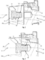
- a disc brake including a first preferred embodiment of the invention in a perspective view;
- Fig. 2:
- a sectional detail view of a brake pad of the disc brake of
Fig.1 ; - Fig. 3:
- the brake pad according to
Fig. 2 in another mounting state; - Fig. 4:
- a sectional detail view of a brake pad of the disc brake of
Fig. 1 according to another preferred embodiment; - Fig. 5:
- the brake pad according to
Fig. 4 in another mounting state; - Fig. 6:
- the wear indication device and the clamping member of the brake pad according to
Figs. 2 and 3 in a perspective view; and - Fig. 7:
- a clamping member according to a preferred embodiment.
-
Fig. 1 shows adisc brake 1 comprising abrake carrier 10, which is mountable to a corresponding receiving section of a vehicle. Thedisc brake 1 further comprises abrake caliper 20, which forms an accommodation space for, among others,brake pads 40, each comprising abrake pad carrier 30, each having a friction lining 40a that comes into contact with the disc of the brake (not shown) during braking in order to apply a braking force. - The
brake pad carrier 30 extends completely over the inner surface of thebrake caliper 20 and projects beyond the upper periphery of thebrake caliper 20. In the projecting region are one or more attachment counterparts provided. - Each of the
brake pad carriers 30 has asupport surface 32 configured to carry one of thefriction linings 40a. - Further, the
brake pad carrier 30 has awear indication device 34 mounted to it which is configured to assess the degree of wear of thebrake pads 40 and in particular of the friction lining 40a. Thewear indication device 34 is coupled to thebrake pad carrier 30 and least partly received in a recess (seeFig. 2 ) of thebrake pad carrier 30. - Each of the
brake pads 40 has a cut-out 42 surrounding the recess (seeFig. 2 ) such that the recess is arranged within the region of the cut-out 42. Thus, thewear indication device 34 is surrounded by thebrake pad 40 wherein the cut-out 42 allows an easy access to thewear indication device 34 without requiring demounting of thebrake pads 40. - The two
brake pad carriers 30 each carrying one of thebrake pads 40 are held in position by aspring hanger 50. - The
spring hanger 50 is preferably connected to thebrake caliper 20 by aspring hanger seat 54 on one side and by a spring hanger fixation means 52 on the other side. After releasing the spring hanger fixation means 52 and guiding thespring hanger 50 out of itsseat 54, thespring hanger 50 may be removed. When thespring hanger 50 is removed, thebrake pads 40 may be removed likewise and be exchanged. - The
wear indication device 34 is coupled to asignal cable 60 having a connector on its distal end. -
Figs. 2 and 3 show thebrake pad carrier 30 and thewear indication device 34 according to a first preferred embodiment in a sectional view. - In
Fig. 2 , thewear indication device 34 is positioned just before therecess 38 of thebrake pad carrier 30. By a movement along an axial direction A of therecess 38, thewear indication device 34 comes into the position shown inFig. 3 , in which thewear indication device 34 is at least partly received in therecess 38. - The
wear indication device 34 further has ahead portion 344 which comes into contact with thesupport surface 32 when theshaft portion 342 is inserted into therecess 38 as shown inFig. 3 . - The
brake pad carrier 30 further has the clampingmember 39, which at least partly surrounds theshaft portion 342. The clampingmember 39 is configured to rest against an inner surface of the recess 38 (seeFig. 3 ) and to apply a clamping force in radial direction on thewear indication device 34 in order to couple thewear indication device 34 with therecess 38 of thebrake pad carrier 30. - The wear indication device 34 (see also
Fig. 6 ) has acircumferential groove 346 at least partly receiving the clampingmember 39. The clampingmember 39 rests at least partly against an inner wall of thegroove 346 such that the clampingmember 39 is repeatable positioned with respect to the length of theshaft portion 342. - The clamping
member 39 has a circular cross-sectional area and the circumferential groove, according to this preferred embodiment, has a rectangular cross-sectional area such that the clampingmember 39 can perform evasive or compensating movements into the corners of thecircumferential groove 346 when shear forces are acting on the clampingmember 39 during insertion of thewear indication device 34 together with the clampingmember 39 into therecess 38. There are also other cross-sectional areas defining thecircumferential groove 346 within the scope of the invention having for example a polygonal cross-sectional area or a groove having the sharp inner corners as shown inFig. 2 , but radial tapered outer corners. - Preferably, the
recess 38 has a radially inwards tapered entrance portion 382 (seeFig. 2 ) such that the insertion of thewear indication device 34 and in particular the clampingmember 39 is guided by said taperedentrance portion 382. - The preferred embodiment, shown in
Figs. 4 and 5 , differs from the first preferred embodiment, shown inFigs. 2 and 3 , in that the shaft portion 342' has astop shoulder 348 instead of a groove, wherein the clampingmember 39 rests against thestop shoulder 348. By having such astop shoulder 348, the clampingmember 39 is repeatable positioned with respect to the length of the shaft portion 342'. Thestop shoulder 348 forms a circumferential corner 347 (seeFig. 4 ) with the distal end of the shaft portion 342', wherein the clampingmember 39 can move into saidcorner 347 when shear forces are acting on the clampingmember 39 during insertion of the wear indication device 34' together with the clampingmember 39 into therecess 38. - In order to perform evasive or compensating movements as described above, the clamping
member 39 has to be elastically deformable in such a way that the clampingmember 39 can deflect upon shear forces acting on the clampingmember 39 when being inserted into therecess 38 together with thewear indication device 34, 34'. - As best shown in
Fig. 6 , thewear indication device 34 has a part-cylindrical orcylindrical shaft portion 342 extending in axial direction A. - It will be understood that the term "part-cylindrical or partially cylindrical" comprises designs in which the shaft portion has at least a part being cylindrical along the axial direction wherein adjacent parts can have other cross-sectional areas as for example a polygonal form. The term also implies other preferred embodiments, as for example a shaft portion extending in the axial direction A and having a circular cross-sectional area, wherein at least one part-circular segment is removed, and wherein the part-circular segment is defined by a secant and the respective segment of the circumference of the cross-sectional area separated by the secant. Due to the removed cross-sections, the part of the outer surface forming a
lateral surface 349 of the cylindrical part of theshaft portion 342 function as guiding surfaces when inserting thewear indication device 34 into the recess 38 (seeFig. 2 ). - Further designs of the clamping
member 39 are within the scope of the invention as for example the embodiment shown inFig. 7 . It will be understood that any kind of clamping member described herein can rest against thestop shoulder 348 as shown inFigs. 4 and 5 or being at least partly received in thegroove 346 as shown inFigs. 2 and 3 . - Anyway, a person skilled in the art will recognize some design measures that can be done in order to improve the positioning of the clamping
member 39. - In the embodiments shown in
Figs. 2 to 6 , the clampingmember 39 comprises an elastomeric material that allows an elastic deformation upon the forces acting on the clampingmember 39 when inserting thewear indication device 34 together with the clampingmember 39 into the recess 38 (seeFigs. 2 to 4 ). Thus, inFigs. 2 to 6 , the clampingmember 39 comprises an O-ring which is at least partly received in the groove 348 (seeFigs. 2 to 3 ) or rests against the stop shoulder 348 (seeFigs. 4 and 5 ). -
Fig. 7 shows another preferred embodiment of the clamping member 39' in which the clamping member 39' comprises or consists of a star washer. - In an alternative embodiment (not shown), there can be a tolerance provided between the
wear indication device 34 and therecess 38 such that a ring-shaped slotted clamping member can be arranged coaxially to the axial direction A such that the clamping member can perform evasive or compensating movements by moving the distal ends of the slotted ring-shaped clamping member towards each other within thegroove 346 or along thestop shoulder 348. -
- 1
- disk brake
- 10
- brake carrier
- 20
- brake caliper
- 30
- brake pad carrier
- 32
- support surface
- 34, 34'
- indication device
- 38
- recess
- 39, 39'
- clamping member
- 40
- brake pad
- 40a
- friction lining
- 42
- cut-out
- 50
- spring hanger
- 52
- hanger coupling means
- 54
- hanger seat
- 60
- signal cable
- 342, 342'
- shaft portion
- 344
- head portion
- 347
- corner
- 346
- groove
- 348
- stop shoulder
- 349
- lateral surface
- 382
- tapered entrance portion
- A
- axial direction
Claims (16)
- Brake pad (40) of a vehicle brake (1), in particular of a disc brake of a commercial vehicle, the brake pad (40) comprising:- a brake pad carrier (30) having a support surface (32),- a friction lining (40a) attached to the support surface (32)- a recess (38) extending from the support surface (32) in an axial direction, and- a wear indication device (34) arranged at least partially inside the recess (38),characterized in that the brake pad carrier (30) further has a clamping member (39, 39') resting against an inner wall of the recess (38), wherein the clamping member (39, 39') is configured to apply a clamping force on the wear indication device (34) in a radial direction.
- Brake pad (40) according to claim 1,
wherein the wear indication device (34) has a shaft portion (342, 342') being received in the recess (38) and a head portion (344) resting against the support surface (32), wherein the shaft portion (342, 342') is configured to couple the wear indication device (34) to the brake pad carrier (30). - Brake pad (40) according to claim 2,
wherein the shaft portion (342, 342') is at least part-cylindrical and the clamping member (39, 39') extends at least partially circumferentially around the shaft portion (342, 342'). - Brake pad (40) according to claim 2 or 3,
wherein the shaft portion (342) has a circumferential groove (346) at least partly receiving the clamping member (39, 39'). - Brake pad (40) according to claim 4,
wherein the groove (346) has a first transverse extension in circumferential direction and the clamping member (39, 39') has a second transverse extension in circumferential direction, and wherein the first transverse extension is larger than the second transverse extension. - Brake pad (40) according to claim 4 or 5,
wherein the groove (346) is defined by a base side and at a first and at least one second side both extending at an angle that is equal, preferably larger than 90° from the base side, and, wherein the clamping member (39, 39') is at least partly received between the first and the second side. - Brake pad (40) according to one of the claims 2 to 6,
wherein the shaft portion (342') has a stop shoulder (348) and the clamping member (39, 39') is resting against the stop shoulder (348). - Brake pad (40) according to any one of claims 4 to7,
wherein the stop shoulder (348) or the groove (346) is arranged in the distal half of the shaft portion (342, 342'). - Brake pad (40) according to one of the claims 2 to 8,
wherein the shaft portion (342, 342') has a length that is at least equal to, preferably exceeding the width or depth or diameter of the shaft portion (342). - Brake pad (40) according to one of the preceding claims,
wherein the clamping member (39) comprises an elastomeric material. - Brake pad (40) according to any one of the preceding claims,
wherein the clamping member (39, 39') has an O-ring arranged around the shaft portion (342, 342') of the wear indication device (34, 34'). - Brake pad (40) according to one of the preceding claims,
wherein the clamping member (39, 39') comprises a spring steel. - Brake pad (40) according to claim 12,
wherein the clamping member (39') has a star washer arranged around the shaft portion (342) of the wear indication device (34, 34'), and/or
the clamping member (39') has a slotted ring, preferably a retaining ring or a snap ring or a slotted ring formed of an undulated spring band material, arranged around the shaft portion (342, 342') of the wear indication device (34, 34'). - Vehicle brake (1), in particular disc brake of a commercial vehicle, the vehicle brake (1) comprising:- a brake disc,- a brake pad (40) having a friction lining (40a), wherein the friction lining (40a) is configured to bear against the brake disc during braking, and a brake pad carrier (30) configured to carry the friction lining (40a) proximate to the brake disc, the brake pad carrier (30) comprising:characterized in that the brake bad carrier (30) is formed according to any one of the preceding claims.- a support surface (32) for carrying the brake pad (40),- a recess (38) extending from the support surface (32) in an axial direction (A), and- a wear indication device (34, 34') arranged at least partially inside the recess (38),
- Vehicle brake (1) according to claim 14,
wherein the brake pad (40) has cut-out (42) surrounding the recess (38), such that the recess (38) is arranged within the region of the cut-out (42). - Method for assembling a vehicle brake (1), in particular a disc brake of a commercial vehicle, the method comprising the steps:- arranging a clamping member (39, 39') around a wear indication device (34, 34'), in particular around a shaft portion (342, 342') of the wear indication device (34, 34'), wherein the clamping member (39, 39') is preferably at least partly received in a circumferential groove (346) of the wear indication device (34, 34'),- arranging the wear indication device (34, 34') and the clamping member (39, 39') proximate to a recess (38) of a brake pad carrier (30), and- coupling the wear indication device (34, 34') and the brake pad carrier (30) by a linear movement of the wear indication device (34, 34') and the clamping member (39, 39') towards the recess (38) and along an axial direction (A) of the recess (38), such that the wear indication device (34, 34') is at least partly received in the recess (38) and the clamping member (39, 39') rests against an inner wall of the recess (38) thereby applying a clamping force on the wear indication device (34, 34') in radial direction.
Priority Applications (3)
| Application Number | Priority Date | Filing Date | Title |
|---|---|---|---|
| EP20199137.9A EP3978777B1 (en) | 2020-09-30 | 2020-09-30 | Brake pad of a vehicle brake, vehicle brake and method for assembling a vehicle brake |
| CN202111075313.XA CN114321230B (en) | 2020-09-30 | 2021-09-14 | Brake pad for a vehicle brake, vehicle brake and method for assembling a vehicle brake |
| US17/488,861 US11898612B2 (en) | 2020-09-30 | 2021-09-29 | Brake pad of a vehicle brake, vehicle brake and method for assembling a vehicle brake |
Applications Claiming Priority (1)
| Application Number | Priority Date | Filing Date | Title |
|---|---|---|---|
| EP20199137.9A EP3978777B1 (en) | 2020-09-30 | 2020-09-30 | Brake pad of a vehicle brake, vehicle brake and method for assembling a vehicle brake |
Publications (2)
| Publication Number | Publication Date |
|---|---|
| EP3978777A1 true EP3978777A1 (en) | 2022-04-06 |
| EP3978777B1 EP3978777B1 (en) | 2023-11-29 |
Family
ID=72709015
Family Applications (1)
| Application Number | Title | Priority Date | Filing Date |
|---|---|---|---|
| EP20199137.9A Active EP3978777B1 (en) | 2020-09-30 | 2020-09-30 | Brake pad of a vehicle brake, vehicle brake and method for assembling a vehicle brake |
Country Status (3)
| Country | Link |
|---|---|
| US (1) | US11898612B2 (en) |
| EP (1) | EP3978777B1 (en) |
| CN (1) | CN114321230B (en) |
Citations (4)
| Publication number | Priority date | Publication date | Assignee | Title |
|---|---|---|---|---|
| DE202008013226U1 (en) * | 2008-10-08 | 2009-02-26 | Bowa-Electronic Gmbh & Co. Kg | Reibbelagsverschleißsensor |
| EP2182236A1 (en) * | 2008-10-28 | 2010-05-05 | Sadeca Systems. S.L.U. | Wear indicator for the friction lining of an automobile, in particular of a brake lining |
| DE102010048988A1 (en) | 2010-10-20 | 2012-04-26 | Wabco Radbremsen Gmbh | Brake pad wear indicator, disc brake with such a display and brake shoes for such a disc brake |
| EP2532916A1 (en) * | 2011-06-09 | 2012-12-12 | KNORR-BREMSE Systeme für Nutzfahrzeuge GmbH | Brake pad of a disc brake |
Family Cites Families (19)
| Publication number | Priority date | Publication date | Assignee | Title |
|---|---|---|---|---|
| US2725964A (en) * | 1950-05-16 | 1955-12-06 | Ringspann Ges M B H | Friction clutches |
| US3652138A (en) * | 1970-04-23 | 1972-03-28 | Charles H Collett | Self-locking snap-on collar for oil well operations |
| FR2127135A5 (en) * | 1971-02-25 | 1972-10-13 | Ferodo Sa | |
| US4133542A (en) * | 1976-08-31 | 1979-01-09 | Robert Janian | Spring seal |
| US4298857A (en) | 1980-02-01 | 1981-11-03 | Ford Motor Company | Brake wear indicator system |
| DE3233634A1 (en) * | 1981-09-30 | 1983-04-14 | Lucas Industries P.L.C., Birmingham, West Midlands | Brake jaw having a sensor for a wear indicating device |
| AT383403B (en) * | 1983-10-31 | 1987-07-10 | Enfo Grundlagen Forschungs Ag | SPRING WASHER, METHOD FOR PRODUCING THE SAME AND DEVICE FOR CARRYING IT OUT |
| DE4340452A1 (en) * | 1993-11-27 | 1995-06-01 | Teves Gmbh Alfred | Floating calliper disk brake for car |
| EP0978665B1 (en) * | 1998-08-05 | 2004-06-09 | Freni Brembo S.p.A. | Device for indicating lining wear in floating caliper disc brakes |
| US7159857B2 (en) * | 2004-05-24 | 2007-01-09 | Robert Janian | Multi spring ring |
| US8113548B2 (en) * | 2005-06-30 | 2012-02-14 | Ti Group Automotive Systems, Llc | Quick connector for high pressure applications |
| CN201385653Y (en) * | 2009-04-22 | 2010-01-20 | 淄博贝尼托金属制品有限公司 | Automatic alarming disc-type brake |
| CN102667267B (en) * | 2009-12-29 | 2015-11-25 | 美国圣戈班性能塑料公司 | Spring and method of forming it |
| DE102011087140A1 (en) * | 2010-12-09 | 2012-06-14 | Continental Teves Ag & Co. Ohg | Partial lining disc brake with friction lining wear warning device |
| ITMI20111552A1 (en) * | 2011-08-26 | 2013-02-27 | Freni Brembo Spa | ASSEMBLY OF THE WEAR OF A BRAKE PAD OF A DISC BRAKE |
| DE102012102584A1 (en) * | 2012-03-26 | 2013-09-26 | Knorr-Bremse Systeme für Nutzfahrzeuge GmbH | Disc brake with reset device and brake pad |
| CN202971687U (en) * | 2012-11-29 | 2013-06-05 | 贵州新安航空机械有限责任公司 | Wind generator brake with brake pad wear indicating device |
| EP3822505B1 (en) * | 2017-11-29 | 2023-01-04 | Meritor Heavy Vehicle Braking Systems (UK) Limited | Brake continuous wear sensor (cws) located in guide sleeve |
| US10436271B2 (en) * | 2018-02-15 | 2019-10-08 | Bendix Spicer Foundation Brake Llc | Mechanical pad wear indicator |
-
2020
- 2020-09-30 EP EP20199137.9A patent/EP3978777B1/en active Active
-
2021
- 2021-09-14 CN CN202111075313.XA patent/CN114321230B/en active Active
- 2021-09-29 US US17/488,861 patent/US11898612B2/en active Active
Patent Citations (4)
| Publication number | Priority date | Publication date | Assignee | Title |
|---|---|---|---|---|
| DE202008013226U1 (en) * | 2008-10-08 | 2009-02-26 | Bowa-Electronic Gmbh & Co. Kg | Reibbelagsverschleißsensor |
| EP2182236A1 (en) * | 2008-10-28 | 2010-05-05 | Sadeca Systems. S.L.U. | Wear indicator for the friction lining of an automobile, in particular of a brake lining |
| DE102010048988A1 (en) | 2010-10-20 | 2012-04-26 | Wabco Radbremsen Gmbh | Brake pad wear indicator, disc brake with such a display and brake shoes for such a disc brake |
| EP2532916A1 (en) * | 2011-06-09 | 2012-12-12 | KNORR-BREMSE Systeme für Nutzfahrzeuge GmbH | Brake pad of a disc brake |
Also Published As
| Publication number | Publication date |
|---|---|
| US11898612B2 (en) | 2024-02-13 |
| US20220099148A1 (en) | 2022-03-31 |
| EP3978777B1 (en) | 2023-11-29 |
| CN114321230A (en) | 2022-04-12 |
| CN114321230B (en) | 2024-12-27 |
Similar Documents
| Publication | Publication Date | Title |
|---|---|---|
| US8322941B2 (en) | Connecting assembly with securing ring | |
| JP4689992B2 (en) | Connecting device between watch rim and case | |
| CN102159840A (en) | Elastic coupling | |
| US20030006104A1 (en) | Brake disk/hub assembly for vehicle disk brakes | |
| GB2265940A (en) | Ball joint with prestressed plastic bearing bush | |
| JPH02240420A (en) | Friction lining alarming device | |
| US20100206681A1 (en) | Clutch cover assembly | |
| CN102086907B (en) | Axial retention assembly | |
| EP3978777B1 (en) | Brake pad of a vehicle brake, vehicle brake and method for assembling a vehicle brake | |
| KR20040068916A (en) | Fixation of a wiper system | |
| CN115013533A (en) | Split oil seal composed of double springs and double rings | |
| US5690553A (en) | Resilent element having an elastic portion and seat portions for use in a vibration damping device | |
| CN104736870A (en) | Friction clutch | |
| US20160186864A1 (en) | Sealing ring | |
| KR20000035244A (en) | Retaining ring for fixing a release bearing in a release system | |
| US4637806A (en) | Arrangement for mounting swivel pin bearing in yoke of universal joint | |
| US10422394B2 (en) | Disc brake | |
| US20160252128A1 (en) | Fastening Element | |
| CN214367742U (en) | Split oil seal composed of double springs and double rings | |
| CN108603543A (en) | Clutches with floating bearing thrust pads | |
| US4366893A (en) | Torsion damping center for the driven disc of a friction clutch for a motor vehicle | |
| EP2213523B1 (en) | Fixing arrangement with self-centring elements for fixing an airbag module in an automotive vehicle | |
| EP3742017B1 (en) | Vehicle disc brake, pivot bearing for a disc brake and clamping cap for a disc brake | |
| EP1707836B1 (en) | Clutch release structure | |
| JP3737796B2 (en) | Journal bearing structure |
Legal Events
| Date | Code | Title | Description |
|---|---|---|---|
| PUAI | Public reference made under article 153(3) epc to a published international application that has entered the european phase |
Free format text: ORIGINAL CODE: 0009012 |
|
| STAA | Information on the status of an ep patent application or granted ep patent |
Free format text: STATUS: THE APPLICATION HAS BEEN PUBLISHED |
|
| AK | Designated contracting states |
Kind code of ref document: A1 Designated state(s): AL AT BE BG CH CY CZ DE DK EE ES FI FR GB GR HR HU IE IS IT LI LT LU LV MC MK MT NL NO PL PT RO RS SE SI SK SM TR |
|
| STAA | Information on the status of an ep patent application or granted ep patent |
Free format text: STATUS: REQUEST FOR EXAMINATION WAS MADE |
|
| 17P | Request for examination filed |
Effective date: 20221006 |
|
| RBV | Designated contracting states (corrected) |
Designated state(s): AL AT BE BG CH CY CZ DE DK EE ES FI FR GB GR HR HU IE IS IT LI LT LU LV MC MK MT NL NO PL PT RO RS SE SI SK SM TR |
|
| GRAP | Despatch of communication of intention to grant a patent |
Free format text: ORIGINAL CODE: EPIDOSNIGR1 |
|
| STAA | Information on the status of an ep patent application or granted ep patent |
Free format text: STATUS: GRANT OF PATENT IS INTENDED |
|
| INTG | Intention to grant announced |
Effective date: 20230914 |
|
| GRAS | Grant fee paid |
Free format text: ORIGINAL CODE: EPIDOSNIGR3 |
|
| GRAA | (expected) grant |
Free format text: ORIGINAL CODE: 0009210 |
|
| STAA | Information on the status of an ep patent application or granted ep patent |
Free format text: STATUS: THE PATENT HAS BEEN GRANTED |
|
| AK | Designated contracting states |
Kind code of ref document: B1 Designated state(s): AL AT BE BG CH CY CZ DE DK EE ES FI FR GB GR HR HU IE IS IT LI LT LU LV MC MK MT NL NO PL PT RO RS SE SI SK SM TR |
|
| REG | Reference to a national code |
Ref country code: GB Ref legal event code: FG4D |
|
| REG | Reference to a national code |
Ref country code: CH Ref legal event code: EP |
|
| REG | Reference to a national code |
Ref country code: DE Ref legal event code: R096 Ref document number: 602020021784 Country of ref document: DE |
|
| REG | Reference to a national code |
Ref country code: IE Ref legal event code: FG4D |
|
| REG | Reference to a national code |
Ref country code: LT Ref legal event code: MG9D |
|
| REG | Reference to a national code |
Ref country code: NL Ref legal event code: MP Effective date: 20231129 |
|
| PG25 | Lapsed in a contracting state [announced via postgrant information from national office to epo] |
Ref country code: GR Free format text: LAPSE BECAUSE OF FAILURE TO SUBMIT A TRANSLATION OF THE DESCRIPTION OR TO PAY THE FEE WITHIN THE PRESCRIBED TIME-LIMIT Effective date: 20240301 |
|
| PG25 | Lapsed in a contracting state [announced via postgrant information from national office to epo] |
Ref country code: IS Free format text: LAPSE BECAUSE OF FAILURE TO SUBMIT A TRANSLATION OF THE DESCRIPTION OR TO PAY THE FEE WITHIN THE PRESCRIBED TIME-LIMIT Effective date: 20240329 |
|
| PG25 | Lapsed in a contracting state [announced via postgrant information from national office to epo] |
Ref country code: LT Free format text: LAPSE BECAUSE OF FAILURE TO SUBMIT A TRANSLATION OF THE DESCRIPTION OR TO PAY THE FEE WITHIN THE PRESCRIBED TIME-LIMIT Effective date: 20231129 |
|
| PG25 | Lapsed in a contracting state [announced via postgrant information from national office to epo] |
Ref country code: ES Free format text: LAPSE BECAUSE OF FAILURE TO SUBMIT A TRANSLATION OF THE DESCRIPTION OR TO PAY THE FEE WITHIN THE PRESCRIBED TIME-LIMIT Effective date: 20231129 |
|
| PG25 | Lapsed in a contracting state [announced via postgrant information from national office to epo] |
Ref country code: LT Free format text: LAPSE BECAUSE OF FAILURE TO SUBMIT A TRANSLATION OF THE DESCRIPTION OR TO PAY THE FEE WITHIN THE PRESCRIBED TIME-LIMIT Effective date: 20231129 Ref country code: IS Free format text: LAPSE BECAUSE OF FAILURE TO SUBMIT A TRANSLATION OF THE DESCRIPTION OR TO PAY THE FEE WITHIN THE PRESCRIBED TIME-LIMIT Effective date: 20240329 Ref country code: GR Free format text: LAPSE BECAUSE OF FAILURE TO SUBMIT A TRANSLATION OF THE DESCRIPTION OR TO PAY THE FEE WITHIN THE PRESCRIBED TIME-LIMIT Effective date: 20240301 Ref country code: ES Free format text: LAPSE BECAUSE OF FAILURE TO SUBMIT A TRANSLATION OF THE DESCRIPTION OR TO PAY THE FEE WITHIN THE PRESCRIBED TIME-LIMIT Effective date: 20231129 Ref country code: BG Free format text: LAPSE BECAUSE OF FAILURE TO SUBMIT A TRANSLATION OF THE DESCRIPTION OR TO PAY THE FEE WITHIN THE PRESCRIBED TIME-LIMIT Effective date: 20240229 |
|
| REG | Reference to a national code |
Ref country code: AT Ref legal event code: MK05 Ref document number: 1636429 Country of ref document: AT Kind code of ref document: T Effective date: 20231129 |
|
| PG25 | Lapsed in a contracting state [announced via postgrant information from national office to epo] |
Ref country code: NL Free format text: LAPSE BECAUSE OF FAILURE TO SUBMIT A TRANSLATION OF THE DESCRIPTION OR TO PAY THE FEE WITHIN THE PRESCRIBED TIME-LIMIT Effective date: 20231129 |
|
| PG25 | Lapsed in a contracting state [announced via postgrant information from national office to epo] |
Ref country code: SE Free format text: LAPSE BECAUSE OF FAILURE TO SUBMIT A TRANSLATION OF THE DESCRIPTION OR TO PAY THE FEE WITHIN THE PRESCRIBED TIME-LIMIT Effective date: 20231129 Ref country code: RS Free format text: LAPSE BECAUSE OF FAILURE TO SUBMIT A TRANSLATION OF THE DESCRIPTION OR TO PAY THE FEE WITHIN THE PRESCRIBED TIME-LIMIT Effective date: 20231129 Ref country code: PL Free format text: LAPSE BECAUSE OF FAILURE TO SUBMIT A TRANSLATION OF THE DESCRIPTION OR TO PAY THE FEE WITHIN THE PRESCRIBED TIME-LIMIT Effective date: 20231129 Ref country code: NO Free format text: LAPSE BECAUSE OF FAILURE TO SUBMIT A TRANSLATION OF THE DESCRIPTION OR TO PAY THE FEE WITHIN THE PRESCRIBED TIME-LIMIT Effective date: 20240229 Ref country code: NL Free format text: LAPSE BECAUSE OF FAILURE TO SUBMIT A TRANSLATION OF THE DESCRIPTION OR TO PAY THE FEE WITHIN THE PRESCRIBED TIME-LIMIT Effective date: 20231129 Ref country code: LV Free format text: LAPSE BECAUSE OF FAILURE TO SUBMIT A TRANSLATION OF THE DESCRIPTION OR TO PAY THE FEE WITHIN THE PRESCRIBED TIME-LIMIT Effective date: 20231129 Ref country code: HR Free format text: LAPSE BECAUSE OF FAILURE TO SUBMIT A TRANSLATION OF THE DESCRIPTION OR TO PAY THE FEE WITHIN THE PRESCRIBED TIME-LIMIT Effective date: 20231129 |
|
| PG25 | Lapsed in a contracting state [announced via postgrant information from national office to epo] |
Ref country code: DK Free format text: LAPSE BECAUSE OF FAILURE TO SUBMIT A TRANSLATION OF THE DESCRIPTION OR TO PAY THE FEE WITHIN THE PRESCRIBED TIME-LIMIT Effective date: 20231129 |
|
| PG25 | Lapsed in a contracting state [announced via postgrant information from national office to epo] |
Ref country code: CZ Free format text: LAPSE BECAUSE OF FAILURE TO SUBMIT A TRANSLATION OF THE DESCRIPTION OR TO PAY THE FEE WITHIN THE PRESCRIBED TIME-LIMIT Effective date: 20231129 Ref country code: AT Free format text: LAPSE BECAUSE OF FAILURE TO SUBMIT A TRANSLATION OF THE DESCRIPTION OR TO PAY THE FEE WITHIN THE PRESCRIBED TIME-LIMIT Effective date: 20231129 |
|
| PG25 | Lapsed in a contracting state [announced via postgrant information from national office to epo] |
Ref country code: SK Free format text: LAPSE BECAUSE OF FAILURE TO SUBMIT A TRANSLATION OF THE DESCRIPTION OR TO PAY THE FEE WITHIN THE PRESCRIBED TIME-LIMIT Effective date: 20231129 |
|
| PG25 | Lapsed in a contracting state [announced via postgrant information from national office to epo] |
Ref country code: SM Free format text: LAPSE BECAUSE OF FAILURE TO SUBMIT A TRANSLATION OF THE DESCRIPTION OR TO PAY THE FEE WITHIN THE PRESCRIBED TIME-LIMIT Effective date: 20231129 Ref country code: SK Free format text: LAPSE BECAUSE OF FAILURE TO SUBMIT A TRANSLATION OF THE DESCRIPTION OR TO PAY THE FEE WITHIN THE PRESCRIBED TIME-LIMIT Effective date: 20231129 Ref country code: RO Free format text: LAPSE BECAUSE OF FAILURE TO SUBMIT A TRANSLATION OF THE DESCRIPTION OR TO PAY THE FEE WITHIN THE PRESCRIBED TIME-LIMIT Effective date: 20231129 Ref country code: IT Free format text: LAPSE BECAUSE OF FAILURE TO SUBMIT A TRANSLATION OF THE DESCRIPTION OR TO PAY THE FEE WITHIN THE PRESCRIBED TIME-LIMIT Effective date: 20231129 Ref country code: EE Free format text: LAPSE BECAUSE OF FAILURE TO SUBMIT A TRANSLATION OF THE DESCRIPTION OR TO PAY THE FEE WITHIN THE PRESCRIBED TIME-LIMIT Effective date: 20231129 Ref country code: DK Free format text: LAPSE BECAUSE OF FAILURE TO SUBMIT A TRANSLATION OF THE DESCRIPTION OR TO PAY THE FEE WITHIN THE PRESCRIBED TIME-LIMIT Effective date: 20231129 Ref country code: CZ Free format text: LAPSE BECAUSE OF FAILURE TO SUBMIT A TRANSLATION OF THE DESCRIPTION OR TO PAY THE FEE WITHIN THE PRESCRIBED TIME-LIMIT Effective date: 20231129 Ref country code: AT Free format text: LAPSE BECAUSE OF FAILURE TO SUBMIT A TRANSLATION OF THE DESCRIPTION OR TO PAY THE FEE WITHIN THE PRESCRIBED TIME-LIMIT Effective date: 20231129 |
|
| PG25 | Lapsed in a contracting state [announced via postgrant information from national office to epo] |
Ref country code: PT Free format text: LAPSE BECAUSE OF FAILURE TO SUBMIT A TRANSLATION OF THE DESCRIPTION OR TO PAY THE FEE WITHIN THE PRESCRIBED TIME-LIMIT Effective date: 20240401 |
|
| REG | Reference to a national code |
Ref country code: DE Ref legal event code: R026 Ref document number: 602020021784 Country of ref document: DE |
|
| PG25 | Lapsed in a contracting state [announced via postgrant information from national office to epo] |
Ref country code: PT Free format text: LAPSE BECAUSE OF FAILURE TO SUBMIT A TRANSLATION OF THE DESCRIPTION OR TO PAY THE FEE WITHIN THE PRESCRIBED TIME-LIMIT Effective date: 20240401 |
|
| PLBI | Opposition filed |
Free format text: ORIGINAL CODE: 0009260 |
|
| PLAB | Opposition data, opponent's data or that of the opponent's representative modified |
Free format text: ORIGINAL CODE: 0009299OPPO |
|
| PLAX | Notice of opposition and request to file observation + time limit sent |
Free format text: ORIGINAL CODE: EPIDOSNOBS2 |
|
| 26 | Opposition filed |
Opponent name: VRI-PATENT MONITORING ASSOCIATION Effective date: 20240829 |
|
| R26 | Opposition filed (corrected) |
Opponent name: VRI-PATENT MONITORING ASSOCIATION Effective date: 20240829 |
|
| PG25 | Lapsed in a contracting state [announced via postgrant information from national office to epo] |
Ref country code: SI Free format text: LAPSE BECAUSE OF FAILURE TO SUBMIT A TRANSLATION OF THE DESCRIPTION OR TO PAY THE FEE WITHIN THE PRESCRIBED TIME-LIMIT Effective date: 20231129 |
|
| PG25 | Lapsed in a contracting state [announced via postgrant information from national office to epo] |
Ref country code: SI Free format text: LAPSE BECAUSE OF FAILURE TO SUBMIT A TRANSLATION OF THE DESCRIPTION OR TO PAY THE FEE WITHIN THE PRESCRIBED TIME-LIMIT Effective date: 20231129 |
|
| PLBB | Reply of patent proprietor to notice(s) of opposition received |
Free format text: ORIGINAL CODE: EPIDOSNOBS3 |
|
| PG25 | Lapsed in a contracting state [announced via postgrant information from national office to epo] |
Ref country code: MC Free format text: LAPSE BECAUSE OF FAILURE TO SUBMIT A TRANSLATION OF THE DESCRIPTION OR TO PAY THE FEE WITHIN THE PRESCRIBED TIME-LIMIT Effective date: 20231129 |
|
| REG | Reference to a national code |
Ref country code: CH Ref legal event code: PL |
|
| PG25 | Lapsed in a contracting state [announced via postgrant information from national office to epo] |
Ref country code: LU Free format text: LAPSE BECAUSE OF NON-PAYMENT OF DUE FEES Effective date: 20240930 |
|
| REG | Reference to a national code |
Ref country code: BE Ref legal event code: MM Effective date: 20240930 |
|
| PG25 | Lapsed in a contracting state [announced via postgrant information from national office to epo] |
Ref country code: BE Free format text: LAPSE BECAUSE OF NON-PAYMENT OF DUE FEES Effective date: 20240930 |
|
| PG25 | Lapsed in a contracting state [announced via postgrant information from national office to epo] |
Ref country code: CH Free format text: LAPSE BECAUSE OF NON-PAYMENT OF DUE FEES Effective date: 20240930 |
|
| PG25 | Lapsed in a contracting state [announced via postgrant information from national office to epo] |
Ref country code: IE Free format text: LAPSE BECAUSE OF NON-PAYMENT OF DUE FEES Effective date: 20240930 |
|
| PG25 | Lapsed in a contracting state [announced via postgrant information from national office to epo] |
Ref country code: FI Free format text: LAPSE BECAUSE OF FAILURE TO SUBMIT A TRANSLATION OF THE DESCRIPTION OR TO PAY THE FEE WITHIN THE PRESCRIBED TIME-LIMIT Effective date: 20231129 |
|
| PGFP | Annual fee paid to national office [announced via postgrant information from national office to epo] |
Ref country code: DE Payment date: 20250805 Year of fee payment: 6 |
|
| PGFP | Annual fee paid to national office [announced via postgrant information from national office to epo] |
Ref country code: GB Payment date: 20250807 Year of fee payment: 6 |
|
| PGFP | Annual fee paid to national office [announced via postgrant information from national office to epo] |
Ref country code: FR Payment date: 20250808 Year of fee payment: 6 |
|
| PG25 | Lapsed in a contracting state [announced via postgrant information from national office to epo] |
Ref country code: CY Free format text: LAPSE BECAUSE OF FAILURE TO SUBMIT A TRANSLATION OF THE DESCRIPTION OR TO PAY THE FEE WITHIN THE PRESCRIBED TIME-LIMIT; INVALID AB INITIO Effective date: 20200930 |
|
| PG25 | Lapsed in a contracting state [announced via postgrant information from national office to epo] |
Ref country code: HU Free format text: LAPSE BECAUSE OF FAILURE TO SUBMIT A TRANSLATION OF THE DESCRIPTION OR TO PAY THE FEE WITHIN THE PRESCRIBED TIME-LIMIT; INVALID AB INITIO Effective date: 20200930 |