EP3978729A1 - Gas turbine engine probe cooling - Google Patents
Gas turbine engine probe cooling Download PDFInfo
- Publication number
- EP3978729A1 EP3978729A1 EP21200783.5A EP21200783A EP3978729A1 EP 3978729 A1 EP3978729 A1 EP 3978729A1 EP 21200783 A EP21200783 A EP 21200783A EP 3978729 A1 EP3978729 A1 EP 3978729A1
- Authority
- EP
- European Patent Office
- Prior art keywords
- engine
- oil
- probe
- gas turbine
- oil cavity
- Prior art date
- Legal status (The legal status is an assumption and is not a legal conclusion. Google has not performed a legal analysis and makes no representation as to the accuracy of the status listed.)
- Pending
Links
Images



Classifications
-
- F—MECHANICAL ENGINEERING; LIGHTING; HEATING; WEAPONS; BLASTING
- F01—MACHINES OR ENGINES IN GENERAL; ENGINE PLANTS IN GENERAL; STEAM ENGINES
- F01D—NON-POSITIVE DISPLACEMENT MACHINES OR ENGINES, e.g. STEAM TURBINES
- F01D25/00—Component parts, details, or accessories, not provided for in, or of interest apart from, other groups
- F01D25/18—Lubricating arrangements
- F01D25/183—Sealing means
-
- F—MECHANICAL ENGINEERING; LIGHTING; HEATING; WEAPONS; BLASTING
- F01—MACHINES OR ENGINES IN GENERAL; ENGINE PLANTS IN GENERAL; STEAM ENGINES
- F01D—NON-POSITIVE DISPLACEMENT MACHINES OR ENGINES, e.g. STEAM TURBINES
- F01D11/00—Preventing or minimising internal leakage of working-fluid, e.g. between stages
- F01D11/003—Preventing or minimising internal leakage of working-fluid, e.g. between stages by packing rings; Mechanical seals
-
- F—MECHANICAL ENGINEERING; LIGHTING; HEATING; WEAPONS; BLASTING
- F01—MACHINES OR ENGINES IN GENERAL; ENGINE PLANTS IN GENERAL; STEAM ENGINES
- F01D—NON-POSITIVE DISPLACEMENT MACHINES OR ENGINES, e.g. STEAM TURBINES
- F01D21/00—Shutting-down of machines or engines, e.g. in emergency; Regulating, controlling, or safety means not otherwise provided for
- F01D21/003—Arrangements for testing or measuring
-
- F—MECHANICAL ENGINEERING; LIGHTING; HEATING; WEAPONS; BLASTING
- F01—MACHINES OR ENGINES IN GENERAL; ENGINE PLANTS IN GENERAL; STEAM ENGINES
- F01D—NON-POSITIVE DISPLACEMENT MACHINES OR ENGINES, e.g. STEAM TURBINES
- F01D25/00—Component parts, details, or accessories, not provided for in, or of interest apart from, other groups
- F01D25/18—Lubricating arrangements
- F01D25/20—Lubricating arrangements using lubrication pumps
-
- F—MECHANICAL ENGINEERING; LIGHTING; HEATING; WEAPONS; BLASTING
- F02—COMBUSTION ENGINES; HOT-GAS OR COMBUSTION-PRODUCT ENGINE PLANTS
- F02C—GAS-TURBINE PLANTS; AIR INTAKES FOR JET-PROPULSION PLANTS; CONTROLLING FUEL SUPPLY IN AIR-BREATHING JET-PROPULSION PLANTS
- F02C7/00—Features, components parts, details or accessories, not provided for in, or of interest apart form groups F02C1/00 - F02C6/00; Air intakes for jet-propulsion plants
- F02C7/06—Arrangements of bearings; Lubricating
-
- F—MECHANICAL ENGINEERING; LIGHTING; HEATING; WEAPONS; BLASTING
- F02—COMBUSTION ENGINES; HOT-GAS OR COMBUSTION-PRODUCT ENGINE PLANTS
- F02C—GAS-TURBINE PLANTS; AIR INTAKES FOR JET-PROPULSION PLANTS; CONTROLLING FUEL SUPPLY IN AIR-BREATHING JET-PROPULSION PLANTS
- F02C7/00—Features, components parts, details or accessories, not provided for in, or of interest apart form groups F02C1/00 - F02C6/00; Air intakes for jet-propulsion plants
- F02C7/36—Power transmission arrangements between the different shafts of the gas turbine plant, or between the gas-turbine plant and the power user
-
- F—MECHANICAL ENGINEERING; LIGHTING; HEATING; WEAPONS; BLASTING
- F01—MACHINES OR ENGINES IN GENERAL; ENGINE PLANTS IN GENERAL; STEAM ENGINES
- F01D—NON-POSITIVE DISPLACEMENT MACHINES OR ENGINES, e.g. STEAM TURBINES
- F01D17/00—Regulating or controlling by varying flow
- F01D17/02—Arrangement of sensing elements
- F01D17/08—Arrangement of sensing elements responsive to condition of working-fluid, e.g. pressure
- F01D17/085—Arrangement of sensing elements responsive to condition of working-fluid, e.g. pressure to temperature
-
- F—MECHANICAL ENGINEERING; LIGHTING; HEATING; WEAPONS; BLASTING
- F05—INDEXING SCHEMES RELATING TO ENGINES OR PUMPS IN VARIOUS SUBCLASSES OF CLASSES F01-F04
- F05D—INDEXING SCHEME FOR ASPECTS RELATING TO NON-POSITIVE-DISPLACEMENT MACHINES OR ENGINES, GAS-TURBINES OR JET-PROPULSION PLANTS
- F05D2220/00—Application
- F05D2220/30—Application in turbines
- F05D2220/32—Application in turbines in gas turbines
- F05D2220/324—Application in turbines in gas turbines to drive unshrouded, low solidity propeller
-
- F—MECHANICAL ENGINEERING; LIGHTING; HEATING; WEAPONS; BLASTING
- F05—INDEXING SCHEMES RELATING TO ENGINES OR PUMPS IN VARIOUS SUBCLASSES OF CLASSES F01-F04
- F05D—INDEXING SCHEME FOR ASPECTS RELATING TO NON-POSITIVE-DISPLACEMENT MACHINES OR ENGINES, GAS-TURBINES OR JET-PROPULSION PLANTS
- F05D2220/00—Application
- F05D2220/30—Application in turbines
- F05D2220/32—Application in turbines in gas turbines
- F05D2220/329—Application in turbines in gas turbines in helicopters
-
- F—MECHANICAL ENGINEERING; LIGHTING; HEATING; WEAPONS; BLASTING
- F05—INDEXING SCHEMES RELATING TO ENGINES OR PUMPS IN VARIOUS SUBCLASSES OF CLASSES F01-F04
- F05D—INDEXING SCHEME FOR ASPECTS RELATING TO NON-POSITIVE-DISPLACEMENT MACHINES OR ENGINES, GAS-TURBINES OR JET-PROPULSION PLANTS
- F05D2240/00—Components
- F05D2240/55—Seals
-
- F—MECHANICAL ENGINEERING; LIGHTING; HEATING; WEAPONS; BLASTING
- F05—INDEXING SCHEMES RELATING TO ENGINES OR PUMPS IN VARIOUS SUBCLASSES OF CLASSES F01-F04
- F05D—INDEXING SCHEME FOR ASPECTS RELATING TO NON-POSITIVE-DISPLACEMENT MACHINES OR ENGINES, GAS-TURBINES OR JET-PROPULSION PLANTS
- F05D2250/00—Geometry
- F05D2250/30—Arrangement of components
- F05D2250/31—Arrangement of components according to the direction of their main axis or their axis of rotation
- F05D2250/312—Arrangement of components according to the direction of their main axis or their axis of rotation the axes being parallel to each other
-
- F—MECHANICAL ENGINEERING; LIGHTING; HEATING; WEAPONS; BLASTING
- F05—INDEXING SCHEMES RELATING TO ENGINES OR PUMPS IN VARIOUS SUBCLASSES OF CLASSES F01-F04
- F05D—INDEXING SCHEME FOR ASPECTS RELATING TO NON-POSITIVE-DISPLACEMENT MACHINES OR ENGINES, GAS-TURBINES OR JET-PROPULSION PLANTS
- F05D2260/00—Function
- F05D2260/20—Heat transfer, e.g. cooling
-
- F—MECHANICAL ENGINEERING; LIGHTING; HEATING; WEAPONS; BLASTING
- F05—INDEXING SCHEMES RELATING TO ENGINES OR PUMPS IN VARIOUS SUBCLASSES OF CLASSES F01-F04
- F05D—INDEXING SCHEME FOR ASPECTS RELATING TO NON-POSITIVE-DISPLACEMENT MACHINES OR ENGINES, GAS-TURBINES OR JET-PROPULSION PLANTS
- F05D2260/00—Function
- F05D2260/40—Transmission of power
- F05D2260/403—Transmission of power through the shape of the drive components
- F05D2260/4031—Transmission of power through the shape of the drive components as in toothed gearing
-
- F—MECHANICAL ENGINEERING; LIGHTING; HEATING; WEAPONS; BLASTING
- F05—INDEXING SCHEMES RELATING TO ENGINES OR PUMPS IN VARIOUS SUBCLASSES OF CLASSES F01-F04
- F05D—INDEXING SCHEME FOR ASPECTS RELATING TO NON-POSITIVE-DISPLACEMENT MACHINES OR ENGINES, GAS-TURBINES OR JET-PROPULSION PLANTS
- F05D2260/00—Function
- F05D2260/98—Lubrication
-
- F—MECHANICAL ENGINEERING; LIGHTING; HEATING; WEAPONS; BLASTING
- F05—INDEXING SCHEMES RELATING TO ENGINES OR PUMPS IN VARIOUS SUBCLASSES OF CLASSES F01-F04
- F05D—INDEXING SCHEME FOR ASPECTS RELATING TO NON-POSITIVE-DISPLACEMENT MACHINES OR ENGINES, GAS-TURBINES OR JET-PROPULSION PLANTS
- F05D2270/00—Control
- F05D2270/80—Devices generating input signals, e.g. transducers, sensors, cameras or strain gauges
-
- Y—GENERAL TAGGING OF NEW TECHNOLOGICAL DEVELOPMENTS; GENERAL TAGGING OF CROSS-SECTIONAL TECHNOLOGIES SPANNING OVER SEVERAL SECTIONS OF THE IPC; TECHNICAL SUBJECTS COVERED BY FORMER USPC CROSS-REFERENCE ART COLLECTIONS [XRACs] AND DIGESTS
- Y02—TECHNOLOGIES OR APPLICATIONS FOR MITIGATION OR ADAPTATION AGAINST CLIMATE CHANGE
- Y02T—CLIMATE CHANGE MITIGATION TECHNOLOGIES RELATED TO TRANSPORTATION
- Y02T50/00—Aeronautics or air transport
- Y02T50/60—Efficient propulsion technologies, e.g. for aircraft
Definitions
- the application relates generally to gas turbine engines and, more particularly, to probe cooling in hot sections of gas turbine engines.
- a gas turbine engine includes sections at low temperatures, namely cold section modules, and sections at high temperatures, namely hot section modules.
- the cold section modules include for example the compressor, while the hot section modules include for example, the combustor and the turbine. While some mechanical components may sustain the high temperatures of the hot section module, probes may not sustain these high temperatures, and their functioning could be altered by the hot ambient gases of the hot section modules.
- a gas turbine engine having an engine centerline comprising: a hot section including: a housing exposed to a high temperature environment, the housing having a circumferentially extending wall extending around the engine centerline and circumscribing an oil cavity, the circumferentially extending wall having a sealing interface at an inner diameter thereof, the sealing interface having a central axis offset from the engine centerline, the housing further having a boss formed in a portion of said circumferentially extending wall on a side of the engine centerline corresponding to an offset between the central axis of the sealing interface and the engine centerline when viewed in an axial cross-section plane containing the engine centerline and the central axis; and a probe mounted to said boss, said probe projecting into the oil cavity so as to be surrounded with oil, the oil thermally insulating the probe from the high temperature environment.
- the gas turbine engine further comprises an oil scavenge port, the oil scavenge port being provided on a side of the engine centerline opposite to the side on which the boss is disposed, the oil scavenge port being closer to the engine centerline than the boss.
- the boss and the oil scavenge port are respectively provided at a top and a bottom end of the housing, the top end being farther from the engine centerline than the bottom end.
- the sealing interface sealingly cooperates with a cover of a reduction gearbox, the cover having an annular sealing flange eccentrically disposed relative to the engine centerline.
- said sealing interface includes an O-ring groove defined in said inner diameter of the circumferentially extending wall, the O-ring groove being off-centered relative to the engine centerline.
- the boss has a tubular body projecting into the oil cavity, the probe extending through said tubular body into the oil cavity to a location next to a power turbine shaft.
- the oil cavity defines an annulus around the tubular body.
- the housing is a power turbine housing disposed next to an engine exhaust, and wherein the sealing interface is sealingly engaged with an annular flange projecting axially from a cover of a reduction gearbox.
- the oil cavity is fluidly connected to the reduction gearbox via a shaft opening defined in the cover, the shaft opening coaxial to the engine centerline.
- the gas turbine engine includes a power turbine having a power turbine shaft extending axially through the oil cavity, the probe having a tip disposed next to the power turbine shaft, wherein the power turbine shaft is offset relative to the central axis of the sealing interface of the housing.
- the housing has first and second axially spaced-apart ends coaxial to the engine centerline, and wherein the sealing interface is axially disposed at an intermediate location between said first and second axially spaced-apart ends.
- a probe mounting arrangement for use in a hot section of a gas turbine engine having an engine centerline
- the probe mounting arrangement comprising: a housing having a circumferentially extending wall circumscribing an oil cavity having a first end coaxial to said engine centerline and a second end having a central axis offset from said engine centerline, the circumferentially extending wall having a boss formed thereon at said second end, the boss having a tubular body projecting into the oil cavity, the tubular body exposed to oil in the oil cavity; and a probe protruding through said tubular body into the oil cavity.
- the circumferentially extending wall has a sealing interface at an inner diameter of said second end, the sealing interface being eccentrically disposed relative to the engine centerline.
- the sealing interface includes an O-ring groove defined in said inner diameter of the circumferentially extending wall, the O-ring groove being off-centered relative to the engine centerline.
- the oil cavity defines an annulus around the tubular body.
- the housing is a power turbine housing, and wherein the sealing interface is sealingly engaged with an annular flange projecting axially from a cover of a reduction gearbox (RGB).
- RGB reduction gearbox
- the boss is provided in a portion of said circumferentially extending wall on a side of the engine centerline corresponding to an offset between the central axis of the second end and the engine centerline when viewed in a plane containing the engine centerline and the central axis.
- the boss is provided on a top portion of the circumferentially extending wall.
- a method of cooling a probe in a hot section of a gas turbine engine having an engine centerline comprising: mounting the probe in a boss formed on a circumferentially extending wall of an oil cavity through which a turbine shaft extends, the probe having a tubular body projecting inwardly into the oil cavity.
- the method further comprises surrounding the probe with oil in the oil cavity.
- the method further comprises configuring the oil cavity to include an off-centered extension in an upward direction away from the engine centerline so that the probe be surrounded on all sides by the oil in the oil cavity.
- the method further comprises forming the boss into an open ended tubular body projecting inwardly into the oil cavity, the open ended tubular body surrounded by the oil contained in the oil cavity.
- Fig. 1 illustrates a gas turbine engine 10 of a type preferably provided for use in subsonic flight, generally comprising in serial flow communication an air inlet 11, a compressor 12 for pressurizing the air from the air inlet 11, a combustor 13 in which the compressed air is mixed with fuel and ignited for generating an annular stream of hot combustion gases, a turbine 14 for extracting energy from the combustion gases, and an exhaust 15 through which the combustion gases exit the engine 10.
- the turbine 14 includes a low pressure or power turbine 14a drivingly connected to an input end of a fully enclosed reduction gearbox RGB 16.
- the RGB 16 has an output end drivingly connected to an output shaft 18 configured to drive a rotatable load (not shown).
- the rotatable load can, for instance, take the form of a propeller or a rotor, such as a helicopter main rotor.
- the gas turbine engine 10 has an engine centerline 17. According to the illustrated embodiment, the compressor and the turbine rotors are mounted in-line for rotation about the engine centerline 17.
- the gas turbine engine 10 has an axially extending central core which defines an annular gaspath 20 through which gases flow, as depicted by flow arrows in Fig. 1 .
- the exemplary embodiment shown in Fig. 1 is a "reverse-flow" engine because gases flow through the gaspath 20 from the air inlet 11 at a rear portion thereof, to the exhaust 15 at a front portion thereof.
- the engine 10 can have an engine architecture corresponding to that of the engine described in applicant's US Patent No. 10,393,027 issued on August 27, 2019 , the entire content of which is herein incorporated by reference.
- the engine 10 has a cold section C that is under a "relatively" cold ambient temperature.
- the cold section C includes the air inlet 11 and the compressor 12.
- the engine 10 also has a hot section H, which in use, is subject to high temperatures.
- the hot section H includes the combustor 13, the turbine 14 and the exhaust 15.
- the temperatures inside the turbine 14 are typically in excess of 1000 degree.
- the continuous flow of gas to which a turbine is exposed can be at a temperature up to 1700 degree. C.
- the engine 10 is equipped with a plurality of probes (sensors) for measuring various operating parameters, such as torque, speed, distance, temperature, pressure etc. Some of these probes are disposed in the hot section H of the engine 10. Accordingly, these probes need to be able to cope with the high temperatures prevailing in the hot section H of the engine 10. It may thus be necessary to thermally shield the probes in order to maintain the temperature of the probes within acceptable limits.
- Fig. 1 illustrates an example of such a thermally shielded probe. More particularly, Fig. 1 illustrates a power turbine probe 22 mounted to the power turbine housing 24 next to the engine exhaust 15 for measuring an operating parameter (e.g. speed and/or torque) of the power turbine 14a.
- the housing 24 is configured to allow the probe 22 to be surrounded by a body of oil so as to thermally shield the probe 22 from the hot exhaust gases flowing through the engine exhaust 15.
- the positioning of the probe is limited by several physical constrains, such as the position of the engine structures interfacing with the housing 24 and the space available for accommodating the probe next to the engine structure to be monitored.
- the housing 24 interfaces with the RGB 16 and is connected to an oil scavenge system 26 having a scavenge port 26a located at a predetermined position at the bottom dead center of the power turbine housing 24.
- the housing must align with the power turbine spool, which is coaxial to the engine centerline 17.
- the power turbine housing 24 has an "off-centered" oil cavity to allow the probe 22 to be surrounded with oil without compromising the positioning and configuration of the oil scavenge system 26.
- the housing 24 has a circumferentially extending wall 24c extending axially from an upstream end 24a to a downstream end 24b relative to the flow of gases flowing through the gas path 20.
- the upstream and downstream ends 24a, 24b are centered relative to the engine centerline 17.
- the circumferentially extending wall 24c has a cylindrical portion 24d extending forwardly from the upstream end 24a.
- the bearings (not shown) supporting the power turbine 14a are disposed in this section of the power turbine housing 24.
- the cylindrical portion 24d merges into a conical portion 24e at a location intermediate the upstream and downstream ends 24a, 24b.
- the conical portion 24e terminates into a radially outer annular flange 24f at the downstream end 24b of the housing 24.
- the annular flange 24f is bolted or otherwise suitably secured to a corresponding flange extending radially outwardly from the enclosure/casing of the RGB 16.
- the RGB enclosure comprises a rear cover 16a having a circular flange 16b projecting axially rearwardly therefrom for sealing engagement with a corresponding sealing interface 24g at an inner diameter of the circumferentially extending wall 24c of the power turbine housing 24.
- the flange 16b of the cover 16a carries an O-ring 28 for sealing engagement in a corresponding O-ring groove 24h ( Fig. 3 ) defined in the sealing interface 24g of the circumferentially extending wall of the housing 24.
- the sealing interface 24g may be provided in the form of an annular inner shoulder projecting axially from an inner surface of the conical portion 24e of the housing for axial engagement over the circular flange 16b of the RGB cover 16a.
- the sealing interface between the cover 16a and the housing 24 seals an end of an oil cavity 30 fluidly connected to a source of oil via an oil supply 32 to provide lubricating to the bearings (not shown) supporting the power turbine 14a.
- the oil cavity 30 is fluidly connected to the RGB 16 via a shaft opening 16c defined in the cover 16a for receiving the power turbine shaft 14b.
- the sealing interface 24g extends about a central axis A that is offset from the engine centerline 17 by a distance D. This provides the required room to position the probe at a top side of the housing 24 into the oil cavity 30 in order to thermally shield the probe 22 without affecting the bearing housing scavenge sump system 26 at the bottom dead center of the housing 24. In other words, it provides for an off-centered oil cavity 30 with an offset in an upward direction sufficient so that the probe 22 be accommodated in the oil cavity 30 circumscribed by the circumferential wall of the housing 24.
- the probe 22 can be mounted in a boss 34 provided at the beginning of the conical section 24e axially adjacent to the sealing interface 24g.
- the boss 34 is formed in a portion of the circumferentially extending wall 24c on a side of the engine centerline 17 corresponding to the offset D between the central axis A of the sealing interface 24g and the engine centerline 17 when viewed in an axial cross-section plane containing the engine centerline 17 and the central axis A as for instance shown in Fig. 4 . It is understood that depending on the application, the side on which the boss 34 is provided is not necessarily the top side of the housing as described above.
- the exemplified boss 34 has an open ended tubular body 34a projecting inwardly into the oil cavity 30. As best shown in Fig. 2 , the tubular body 34a is spaced from the wall 24c of the housing 24 so as to be exposed to the oil on all side (360 degrees exposure). In other words, the tubular body 34a is surrounded by an annulus of oil.
- the probe 22 extends through the tubular body 34 into the oil cavity 30 to a location next to the power turbine shaft 14b. Indeed, as can be appreciated from Fig. 2 , the tip of the probe 22 is disposed beyond the inwardly protruding tubular body 34a of the boss 34 adjacent to the power turbine shaft 14b in the oil cavity 30.
- the boss 34 can be integrated in an annular casting welded or otherwise assembled to the other sections of the housing 24.
- the housing 24 with the boss 34 could be made from stamp sheet metal, machined from solid material or made by 3D printing technologies, such as additive manufacturing.
- cool oil is directed into the oil cavity 30 via the oil supply 32.
- the oil provides lubrication to the bearings (not shown) mounted in the power turbine housing 24 for supporting the power turbine 14a.
- the power turbine shaft 14b rotates, it causes the oil to splash against the inner surface of the circumferentially extending wall 24c and, thus, against the tubular body 34a of the boss 34.
- the rotation of the gears in the RGB 16 also produces oil mist that leaks through the shaft opening 16c of the RGB cover 16a to impinge upon the outer surface of the tubular body 34a and the probe 22.
- the oil around the tubular body 34a of the boss 34 thermally shield the probe 22 from the heat transferred to the turbine housing 24 by the flow of combustion gases prior to being exhausted via exhaust 15.
- the off-centered configuration of the oil cavity 30 allows a probe installation in the power turbine housing 24 without introducing additional complexity in the engine architecture. It provides for a cooler temperature environment for the probe 22 without affecting the position of the oil scavenge system 26.
Landscapes
- Engineering & Computer Science (AREA)
- Mechanical Engineering (AREA)
- General Engineering & Computer Science (AREA)
- Chemical & Material Sciences (AREA)
- Combustion & Propulsion (AREA)
- Supercharger (AREA)
- Gasket Seals (AREA)
- Turbine Rotor Nozzle Sealing (AREA)
Abstract
Description
- The application relates generally to gas turbine engines and, more particularly, to probe cooling in hot sections of gas turbine engines.
- A gas turbine engine includes sections at low temperatures, namely cold section modules, and sections at high temperatures, namely hot section modules. The cold section modules include for example the compressor, while the hot section modules include for example, the combustor and the turbine. While some mechanical components may sustain the high temperatures of the hot section module, probes may not sustain these high temperatures, and their functioning could be altered by the hot ambient gases of the hot section modules.
- In one aspect, there is provided a gas turbine engine having an engine centerline, comprising: a hot section including: a housing exposed to a high temperature environment, the housing having a circumferentially extending wall extending around the engine centerline and circumscribing an oil cavity, the circumferentially extending wall having a sealing interface at an inner diameter thereof, the sealing interface having a central axis offset from the engine centerline, the housing further having a boss formed in a portion of said circumferentially extending wall on a side of the engine centerline corresponding to an offset between the central axis of the sealing interface and the engine centerline when viewed in an axial cross-section plane containing the engine centerline and the central axis; and a probe mounted to said boss, said probe projecting into the oil cavity so as to be surrounded with oil, the oil thermally insulating the probe from the high temperature environment.
- In an embodiment of the foregoing, the gas turbine engine further comprises an oil scavenge port, the oil scavenge port being provided on a side of the engine centerline opposite to the side on which the boss is disposed, the oil scavenge port being closer to the engine centerline than the boss.
- In a further embodiment of any of the foregoing, the boss and the oil scavenge port are respectively provided at a top and a bottom end of the housing, the top end being farther from the engine centerline than the bottom end.
- In a further embodiment of any of the foregoing, the sealing interface sealingly cooperates with a cover of a reduction gearbox, the cover having an annular sealing flange eccentrically disposed relative to the engine centerline.
- In a further embodiment of any of the foregoing, said sealing interface includes an O-ring groove defined in said inner diameter of the circumferentially extending wall, the O-ring groove being off-centered relative to the engine centerline.
- In a further embodiment of any of the foregoing, the boss has a tubular body projecting into the oil cavity, the probe extending through said tubular body into the oil cavity to a location next to a power turbine shaft.
- In a further embodiment of any of the foregoing, the oil cavity defines an annulus around the tubular body.
- In a further embodiment of any of the foregoing, the housing is a power turbine housing disposed next to an engine exhaust, and wherein the sealing interface is sealingly engaged with an annular flange projecting axially from a cover of a reduction gearbox.
- In a further embodiment of any of the foregoing, the oil cavity is fluidly connected to the reduction gearbox via a shaft opening defined in the cover, the shaft opening coaxial to the engine centerline.
- In a further embodiment of any of the foregoing, the gas turbine engine includes a power turbine having a power turbine shaft extending axially through the oil cavity, the probe having a tip disposed next to the power turbine shaft, wherein the power turbine shaft is offset relative to the central axis of the sealing interface of the housing.
- In a further embodiment of any of the foregoing, the housing has first and second axially spaced-apart ends coaxial to the engine centerline, and wherein the sealing interface is axially disposed at an intermediate location between said first and second axially spaced-apart ends.
- In another aspect, there is provided a probe mounting arrangement for use in a hot section of a gas turbine engine having an engine centerline, the probe mounting arrangement comprising: a housing having a circumferentially extending wall circumscribing an oil cavity having a first end coaxial to said engine centerline and a second end having a central axis offset from said engine centerline, the circumferentially extending wall having a boss formed thereon at said second end, the boss having a tubular body projecting into the oil cavity, the tubular body exposed to oil in the oil cavity; and a probe protruding through said tubular body into the oil cavity.
- In an embodiment of the foregoing, the circumferentially extending wall has a sealing interface at an inner diameter of said second end, the sealing interface being eccentrically disposed relative to the engine centerline.
- In a further embodiment of any of the foregoing, the sealing interface includes an O-ring groove defined in said inner diameter of the circumferentially extending wall, the O-ring groove being off-centered relative to the engine centerline.
- In a further embodiment of any of the foregoing, the oil cavity defines an annulus around the tubular body.
- In a further embodiment of any of the foregoing, the housing is a power turbine housing, and wherein the sealing interface is sealingly engaged with an annular flange projecting axially from a cover of a reduction gearbox (RGB).
- In a further embodiment of any of the foregoing, the boss is provided in a portion of said circumferentially extending wall on a side of the engine centerline corresponding to an offset between the central axis of the second end and the engine centerline when viewed in a plane containing the engine centerline and the central axis.
- In a further embodiment of any of the foregoing, the boss is provided on a top portion of the circumferentially extending wall.
- In a further aspect, there is provided a method of cooling a probe in a hot section of a gas turbine engine having an engine centerline, the method comprising: mounting the probe in a boss formed on a circumferentially extending wall of an oil cavity through which a turbine shaft extends, the probe having a tubular body projecting inwardly into the oil cavity.
- In an embodiment of the foregoing, the method further comprises surrounding the probe with oil in the oil cavity.
- In a further embodiment of any of the foregoing, the method further comprises configuring the oil cavity to include an off-centered extension in an upward direction away from the engine centerline so that the probe be surrounded on all sides by the oil in the oil cavity.
- In a further embodiment of any of the foregoing, the method further comprises forming the boss into an open ended tubular body projecting inwardly into the oil cavity, the open ended tubular body surrounded by the oil contained in the oil cavity.
- Reference is now made to the accompanying figures in which:
-
Fig. 1 is a schematic longitudinal/axial cross-section view of a boosted reverse flow gas turbine engine; -
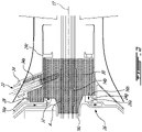
Fig. 2 is an enlarged axial cross-section view of a power turbine housing illustrating an off-centered oil cavity having a front sealing interface extending about a central axis offset from the centerline of the engine, the housing having a boss protruding into the oil cavity for thermally shielding a power turbine probe; -
Fig. 3 is an isometric view of the power turbine housing illustrating the off-centered oil cavity with an eccentric O-ring groove at the front sealing interface; and -
Fig. 4 is an axial cross-section view of the power turbine housing taken in a plane containing the engine centerline and the central axis of the "off-centered" oil cavity. -
Fig. 1 illustrates agas turbine engine 10 of a type preferably provided for use in subsonic flight, generally comprising in serial flow communication anair inlet 11, acompressor 12 for pressurizing the air from theair inlet 11, acombustor 13 in which the compressed air is mixed with fuel and ignited for generating an annular stream of hot combustion gases, aturbine 14 for extracting energy from the combustion gases, and anexhaust 15 through which the combustion gases exit theengine 10. Theturbine 14 includes a low pressure orpower turbine 14a drivingly connected to an input end of a fully enclosedreduction gearbox RGB 16. TheRGB 16 has an output end drivingly connected to anoutput shaft 18 configured to drive a rotatable load (not shown). The rotatable load can, for instance, take the form of a propeller or a rotor, such as a helicopter main rotor. Thegas turbine engine 10 has anengine centerline 17. According to the illustrated embodiment, the compressor and the turbine rotors are mounted in-line for rotation about theengine centerline 17. - The
gas turbine engine 10 has an axially extending central core which defines anannular gaspath 20 through which gases flow, as depicted by flow arrows inFig. 1 . The exemplary embodiment shown inFig. 1 is a "reverse-flow" engine because gases flow through thegaspath 20 from theair inlet 11 at a rear portion thereof, to theexhaust 15 at a front portion thereof. According to one aspect, theengine 10 can have an engine architecture corresponding to that of the engine described in applicant'sUS Patent No. 10,393,027 issued on August 27, 2019 - Still referring to
Fig. 1 , it can be seen that theengine 10 has a cold section C that is under a "relatively" cold ambient temperature. The cold section C includes theair inlet 11 and thecompressor 12. Theengine 10 also has a hot section H, which in use, is subject to high temperatures. The hot section H includes thecombustor 13, theturbine 14 and theexhaust 15. For instance, the temperatures inside theturbine 14 are typically in excess of 1000 degree. C. In use, the continuous flow of gas to which a turbine is exposed can be at a temperature up to 1700 degree. C. - The
engine 10 is equipped with a plurality of probes (sensors) for measuring various operating parameters, such as torque, speed, distance, temperature, pressure etc. Some of these probes are disposed in the hot section H of theengine 10. Accordingly, these probes need to be able to cope with the high temperatures prevailing in the hot section H of theengine 10. It may thus be necessary to thermally shield the probes in order to maintain the temperature of the probes within acceptable limits.Fig. 1 illustrates an example of such a thermally shielded probe. More particularly,Fig. 1 illustrates apower turbine probe 22 mounted to thepower turbine housing 24 next to theengine exhaust 15 for measuring an operating parameter (e.g. speed and/or torque) of thepower turbine 14a. - As shown in
Fig. 2 , thehousing 24 is configured to allow theprobe 22 to be surrounded by a body of oil so as to thermally shield theprobe 22 from the hot exhaust gases flowing through theengine exhaust 15. In practice, the positioning of the probe is limited by several physical constrains, such as the position of the engine structures interfacing with thehousing 24 and the space available for accommodating the probe next to the engine structure to be monitored. For instance, according to the illustrated embodiment, thehousing 24 interfaces with theRGB 16 and is connected to anoil scavenge system 26 having ascavenge port 26a located at a predetermined position at the bottom dead center of thepower turbine housing 24. Also, the housing must align with the power turbine spool, which is coaxial to theengine centerline 17. These structural constrains limit the options available to mount and position theprobe 22 to thepower turbine housing 24. As will be seen herein after, thepower turbine housing 24 has an "off-centered" oil cavity to allow theprobe 22 to be surrounded with oil without compromising the positioning and configuration of theoil scavenge system 26. - Referring concurrently to
Figs. 3 and4 , it can be seen that thehousing 24 has a circumferentially extendingwall 24c extending axially from anupstream end 24a to adownstream end 24b relative to the flow of gases flowing through thegas path 20. The upstream anddownstream ends engine centerline 17. Thecircumferentially extending wall 24c has acylindrical portion 24d extending forwardly from theupstream end 24a. The bearings (not shown) supporting thepower turbine 14a are disposed in this section of thepower turbine housing 24. Thecylindrical portion 24d merges into aconical portion 24e at a location intermediate the upstream anddownstream ends conical portion 24e terminates into a radially outerannular flange 24f at thedownstream end 24b of thehousing 24. As shown inFig. 1 , theannular flange 24f is bolted or otherwise suitably secured to a corresponding flange extending radially outwardly from the enclosure/casing of theRGB 16. - As best shown in
Fig. 2 , the RGB enclosure comprises arear cover 16a having acircular flange 16b projecting axially rearwardly therefrom for sealing engagement with acorresponding sealing interface 24g at an inner diameter of thecircumferentially extending wall 24c of thepower turbine housing 24. According to the illustrated embodiment, theflange 16b of thecover 16a carries an O-ring 28 for sealing engagement in a corresponding O-ring groove 24h (Fig. 3 ) defined in the sealinginterface 24g of the circumferentially extending wall of thehousing 24. As shown inFigs. 2-4 , the sealinginterface 24g may be provided in the form of an annular inner shoulder projecting axially from an inner surface of theconical portion 24e of the housing for axial engagement over thecircular flange 16b of theRGB cover 16a. As depicted by the array of dots inFig. 2 , the sealing interface between thecover 16a and thehousing 24 seals an end of anoil cavity 30 fluidly connected to a source of oil via anoil supply 32 to provide lubricating to the bearings (not shown) supporting thepower turbine 14a. As shown inFig. 2 , theoil cavity 30 is fluidly connected to theRGB 16 via ashaft opening 16c defined in thecover 16a for receiving thepower turbine shaft 14b. It can be appreciated fromFig. 2 that thepower turbine shaft 14b and theshaft opening 16c in thecover 16a are axially aligned with theengine centerline 17. In practice, oil will flow from theRGB 16 to theoil cavity 30 before being evacuated via thescavenge oil port 26a of thescavenge oil system 26. - Now referring concurrently to
Figs. 2 and4 , it can be appreciated that the sealinginterface 24g extends about a central axis A that is offset from theengine centerline 17 by a distance D. This provides the required room to position the probe at a top side of thehousing 24 into theoil cavity 30 in order to thermally shield theprobe 22 without affecting the bearing housingscavenge sump system 26 at the bottom dead center of thehousing 24. In other words, it provides for an off-centeredoil cavity 30 with an offset in an upward direction sufficient so that theprobe 22 be accommodated in theoil cavity 30 circumscribed by the circumferential wall of thehousing 24. - As shown in
Figs. 1-4 , theprobe 22 can be mounted in aboss 34 provided at the beginning of theconical section 24e axially adjacent to the sealinginterface 24g. Theboss 34 is formed in a portion of thecircumferentially extending wall 24c on a side of theengine centerline 17 corresponding to the offset D between the central axis A of the sealinginterface 24g and theengine centerline 17 when viewed in an axial cross-section plane containing theengine centerline 17 and the central axis A as for instance shown inFig. 4 . It is understood that depending on the application, the side on which theboss 34 is provided is not necessarily the top side of the housing as described above. - The exemplified
boss 34 has an open endedtubular body 34a projecting inwardly into theoil cavity 30. As best shown inFig. 2 , thetubular body 34a is spaced from thewall 24c of thehousing 24 so as to be exposed to the oil on all side (360 degrees exposure). In other words, thetubular body 34a is surrounded by an annulus of oil. Theprobe 22 extends through thetubular body 34 into theoil cavity 30 to a location next to thepower turbine shaft 14b. Indeed, as can be appreciated fromFig. 2 , the tip of theprobe 22 is disposed beyond the inwardly protrudingtubular body 34a of theboss 34 adjacent to thepower turbine shaft 14b in theoil cavity 30. - The
boss 34 can be integrated in an annular casting welded or otherwise assembled to the other sections of thehousing 24. Alternatively, thehousing 24 with theboss 34 could be made from stamp sheet metal, machined from solid material or made by 3D printing technologies, such as additive manufacturing. - In operation, cool oil is directed into the
oil cavity 30 via theoil supply 32. The oil provides lubrication to the bearings (not shown) mounted in thepower turbine housing 24 for supporting thepower turbine 14a. As thepower turbine shaft 14b rotates, it causes the oil to splash against the inner surface of thecircumferentially extending wall 24c and, thus, against thetubular body 34a of theboss 34. The rotation of the gears in theRGB 16 also produces oil mist that leaks through theshaft opening 16c of theRGB cover 16a to impinge upon the outer surface of thetubular body 34a and theprobe 22. The oil around thetubular body 34a of theboss 34 thermally shield theprobe 22 from the heat transferred to theturbine housing 24 by the flow of combustion gases prior to being exhausted viaexhaust 15. - It can be appreciated that at least in some aspects, the off-centered configuration of the
oil cavity 30 allows a probe installation in thepower turbine housing 24 without introducing additional complexity in the engine architecture. It provides for a cooler temperature environment for theprobe 22 without affecting the position of theoil scavenge system 26. - The above description is meant to be exemplary only, and one skilled in the art will recognize that changes may be made to the embodiments described without departing from the scope of the invention disclosed. For instance, while the probe installation has been described in the context of a turboprop/turboshaft engine architecture, it is understood that it could be applied to other engines, including turbofan and auxiliary power unit (APU) engines. Also, while the exemplified probe is installed on the power turbine housing, it is understood that it could be installed on other structures of the hot section of the gas turbine engine. Also, it is understood that the present disclosure is not limited to speed or torque probes. Other modifications which fall within the scope of the present invention will be apparent to those skilled in the art, in light of a review of this disclosure, and such modifications are intended to fall within the appended claims.
Claims (14)
- A gas turbine engine (10) having an engine centerline (17), comprising:
a hot section (H) including:a housing (24) exposed to a high temperature environment, the housing (24) having a circumferentially extending wall (24c) extending around the engine centerline (17) and circumscribing an oil cavity (30), the circumferentially extending wall (24c) having a sealing interface (24g) at an inner diameter thereof, the sealing interface (24g) having a central axis (A) offset from the engine centerline (17), the housing (24) further having a boss (34) formed in a portion of said circumferentially extending wall (24c) on a side of the engine centerline (17) corresponding to an offset (D) between the central axis (A) of the sealing interface (24g) and the engine centerline (17) in an axial cross-section plane containing the engine centerline (17) and the central axis (A); anda probe (22) mounted to said boss (34), said probe (22) projecting into the oil cavity (30) so as to be surrounded with oil, the oil thermally insulating the probe (22) from the high temperature environment. - The gas turbine engine (10) according to claim 1, further comprising an oil scavenge port (26a), the oil scavenge port (26a) being provided on a side of the engine centerline (17) opposite to the side on which the boss (34) is disposed, the oil scavenge port (26a) being closer to the engine centerline (17) than the boss (34).
- The gas turbine engine (10) according to claim 2, wherein the boss (34) and the oil scavenge port (26a) are respectively provided at a top and a bottom end of the housing (24), the top end being farther from the engine centerline (17) than the bottom end.
- The gas turbine engine (10) according to any one of claims 1 to 3, wherein the sealing interface (24g) sealingly cooperates with a cover of a reduction gearbox (RGB), the cover (16a) having an annular sealing flange (16b) eccentrically disposed relative to the engine centerline (17).
- The gas turbine engine (10) according to claim 4, wherein said sealing interface (24g) includes an O-ring groove (24h) defined in said inner diameter of the circumferentially extending wall (24c), the O-ring groove (24h) being off-centered relative to the engine centerline (17).
- The gas turbine engine (10) according to any one of claims 1 to 5, wherein the boss (34) has a tubular body (34a) projecting into the oil cavity (30), the probe (22) extending through said tubular body (34a) into the oil cavity (30) to a location next to a power turbine shaft (14b).
- The gas turbine engine (10) according to claim 6, wherein the oil cavity (30) defines an annulus around the tubular body (34a).
- The gas turbine engine (10) according to any one of claims 1 to 7, wherein the housing (24) is a power turbine housing disposed next to an engine exhaust (15), and wherein the sealing interface (24g) is sealingly engaged with an annular flange (16b) projecting axially from a cover (16a) of a reduction gearbox (RGB).
- The gas turbine engine (10) according to claim 8, wherein the oil cavity (30) is fluidly connected to the reduction gearbox (RGB) via a shaft opening (16c) defined in the cover (16a), the shaft opening (16c) coaxial to the engine centerline (17).
- The gas turbine engine (10) according to any one of claims 1 to 9, wherein the gas turbine engine includes a power turbine (14a) having a power turbine shaft (14b) extending axially through the oil cavity (30), the probe (22) having a tip disposed next to the power turbine shaft (14b), wherein the power turbine shaft (14b) is offset relative to the central axis (A) of the sealing interface (24g) of the housing (24).
- The gas turbine engine according to any one of claims 1 to 10, wherein the housing (24) has first and second axially spaced-apart ends coaxial to the engine centerline (17), and wherein the sealing interface (24g) is axially disposed at an intermediate location between said first and second axially spaced-apart ends.
- A method of cooling a probe (22) in a hot section (H) of a gas turbine engine (10) having an engine centerline (17), the method comprising: mounting the probe (22) in a boss (34) formed on a circumferentially extending wall (24c) of an oil cavity (30) through which a turbine shaft (14b) extends, the probe (22) having a tubular body projecting inwardly into the oil cavity; and surrounding the probe (22) with oil in the oil cavity (30).
- The method defined in claim 12, comprising configuring the oil cavity (30) to include an off-centered extension in an upward direction away from the engine centerline (17) so that the probe (22) be surrounded on all sides by the oil in the oil cavity (30).
- The method defined in claim 13, comprising forming the boss (34) into an open ended tubular body (34a) projecting inwardly into the oil cavity (30), the open ended tubular body (34a) surrounded by the oil contained in the oil cavity (30).
Applications Claiming Priority (1)
| Application Number | Priority Date | Filing Date | Title |
|---|---|---|---|
| US17/062,005 US11506080B2 (en) | 2020-10-02 | 2020-10-02 | Gas turbine engine probe cooling |
Publications (1)
| Publication Number | Publication Date |
|---|---|
| EP3978729A1 true EP3978729A1 (en) | 2022-04-06 |
Family
ID=78073862
Family Applications (1)
| Application Number | Title | Priority Date | Filing Date |
|---|---|---|---|
| EP21200783.5A Pending EP3978729A1 (en) | 2020-10-02 | 2021-10-04 | Gas turbine engine probe cooling |
Country Status (3)
| Country | Link |
|---|---|
| US (1) | US11506080B2 (en) |
| EP (1) | EP3978729A1 (en) |
| CA (1) | CA3128049A1 (en) |
Families Citing this family (1)
| Publication number | Priority date | Publication date | Assignee | Title |
|---|---|---|---|---|
| US12467376B1 (en) | 2024-08-02 | 2025-11-11 | Rtx Corporation | Blade tip clearance probe/lead cooling jacket |
Citations (7)
| Publication number | Priority date | Publication date | Assignee | Title |
|---|---|---|---|---|
| EP0539636A1 (en) * | 1991-10-31 | 1993-05-05 | Honda Giken Kogyo Kabushiki Kaisha | Gas turbine engine |
| US20030114267A1 (en) * | 2001-12-14 | 2003-06-19 | Martin Poulin | Zero twist carrier |
| US20040037483A1 (en) * | 2002-08-23 | 2004-02-26 | Gilles Beauvais | Integrated oil transfer sleeve and bearing |
| EP3361122A1 (en) * | 2017-02-10 | 2018-08-15 | Pratt & Whitney Canada Corp. | Planetary gearbox for gas turbine engine |
| EP3361057A2 (en) * | 2017-02-09 | 2018-08-15 | Pratt & Whitney Canada Corp. | Turbine rotor with low over-speed requirements |
| US20180306053A1 (en) * | 2017-04-24 | 2018-10-25 | General Electric Company | Systems and Methods for Electronic Measurement of Propeller Blade Angle |
| US10393027B2 (en) | 2016-07-19 | 2019-08-27 | Pratt & Whitney Canada Corp. | Gas turbine engine shaft architecture and associated method of disassembly |
Family Cites Families (4)
| Publication number | Priority date | Publication date | Assignee | Title |
|---|---|---|---|---|
| US6968697B2 (en) * | 2003-09-17 | 2005-11-29 | Honeywell International Inc. | Integral compressor housing of gas turbine engines |
| US9551281B2 (en) * | 2014-01-15 | 2017-01-24 | Pratt & Whitney Canada Corp. | Electric probe assembly, gas turbine engine having same and method of cooling same |
| US11359512B1 (en) * | 2021-02-02 | 2022-06-14 | Pratt & Whitney Canada Corp. | Torque probe cooling for gas turbine engine using internal fluid flow |
| US11339679B1 (en) * | 2021-03-23 | 2022-05-24 | Pratt & Whitney Canada Corp. | Turbine probe heat shielding |
-
2020
- 2020-10-02 US US17/062,005 patent/US11506080B2/en active Active
-
2021
- 2021-08-12 CA CA3128049A patent/CA3128049A1/en active Pending
- 2021-10-04 EP EP21200783.5A patent/EP3978729A1/en active Pending
Patent Citations (7)
| Publication number | Priority date | Publication date | Assignee | Title |
|---|---|---|---|---|
| EP0539636A1 (en) * | 1991-10-31 | 1993-05-05 | Honda Giken Kogyo Kabushiki Kaisha | Gas turbine engine |
| US20030114267A1 (en) * | 2001-12-14 | 2003-06-19 | Martin Poulin | Zero twist carrier |
| US20040037483A1 (en) * | 2002-08-23 | 2004-02-26 | Gilles Beauvais | Integrated oil transfer sleeve and bearing |
| US10393027B2 (en) | 2016-07-19 | 2019-08-27 | Pratt & Whitney Canada Corp. | Gas turbine engine shaft architecture and associated method of disassembly |
| EP3361057A2 (en) * | 2017-02-09 | 2018-08-15 | Pratt & Whitney Canada Corp. | Turbine rotor with low over-speed requirements |
| EP3361122A1 (en) * | 2017-02-10 | 2018-08-15 | Pratt & Whitney Canada Corp. | Planetary gearbox for gas turbine engine |
| US20180306053A1 (en) * | 2017-04-24 | 2018-10-25 | General Electric Company | Systems and Methods for Electronic Measurement of Propeller Blade Angle |
Also Published As
| Publication number | Publication date |
|---|---|
| US20220106892A1 (en) | 2022-04-07 |
| US11506080B2 (en) | 2022-11-22 |
| CA3128049A1 (en) | 2022-04-02 |
Similar Documents
| Publication | Publication Date | Title |
|---|---|---|
| EP3228836B1 (en) | Conditioned low pressure compressor compartment for gas turbine engine | |
| EP3090209B1 (en) | A cooled grommet for a combustor wall assembly of a gas turbine | |
| US10036279B2 (en) | Thrust bearing | |
| EP3055536B1 (en) | Air cooled fuel injector for a turbine engine | |
| EP4067625B1 (en) | Gas turbine engine including a probe | |
| US20160290157A1 (en) | System for cooling a turbine engine | |
| EP2951404B1 (en) | Gas turbine engine and method | |
| EP3767080A2 (en) | Thermally protected motor/generator for gas turbine engine | |
| US11692871B2 (en) | System and method for disposable imaging system | |
| CN107304713A (en) | Bearing | |
| US20140334916A1 (en) | Borescope inspection port fitting | |
| US20050056019A1 (en) | Integral compressor housing of gas turbine engines | |
| EP4047191B1 (en) | Instrumented turbine exhaust duct | |
| CA3145036A1 (en) | Torque probe cooling for gas turbine engine using external air | |
| EP4299880A1 (en) | Probe heat shielding | |
| US11506080B2 (en) | Gas turbine engine probe cooling | |
| EP3026222B1 (en) | Case assembly for a gas turbine engine and corresponding method of reworking such a case | |
| EP4063620B1 (en) | Thermal protection for a gas turbine engine probe | |
| US11359512B1 (en) | Torque probe cooling for gas turbine engine using internal fluid flow | |
| EP3246522B1 (en) | Internal cooling of stator vanes | |
| US12044169B2 (en) | Sump arrangement for a gas turbine engine | |
| EP3708782B1 (en) | Boas and methods of making a boas having fatigue resistant cooling inlets | |
| EP3650675B1 (en) | Internal heat exchanger system to cool gas turbine engine components | |
| EP4008885B1 (en) | Gas turbine engine combustor |
Legal Events
| Date | Code | Title | Description |
|---|---|---|---|
| PUAI | Public reference made under article 153(3) epc to a published international application that has entered the european phase |
Free format text: ORIGINAL CODE: 0009012 |
|
| STAA | Information on the status of an ep patent application or granted ep patent |
Free format text: STATUS: THE APPLICATION HAS BEEN PUBLISHED |
|
| AK | Designated contracting states |
Kind code of ref document: A1 Designated state(s): AL AT BE BG CH CY CZ DE DK EE ES FI FR GB GR HR HU IE IS IT LI LT LU LV MC MK MT NL NO PL PT RO RS SE SI SK SM TR |
|
| STAA | Information on the status of an ep patent application or granted ep patent |
Free format text: STATUS: REQUEST FOR EXAMINATION WAS MADE |
|
| 17P | Request for examination filed |
Effective date: 20221006 |
|
| RBV | Designated contracting states (corrected) |
Designated state(s): AL AT BE BG CH CY CZ DE DK EE ES FI FR GB GR HR HU IE IS IT LI LT LU LV MC MK MT NL NO PL PT RO RS SE SI SK SM TR |
|
| STAA | Information on the status of an ep patent application or granted ep patent |
Free format text: STATUS: EXAMINATION IS IN PROGRESS |
|
| 17Q | First examination report despatched |
Effective date: 20240613 |