EP3978695A1 - Bendable elevating side spray shower - Google Patents
Bendable elevating side spray shower Download PDFInfo
- Publication number
- EP3978695A1 EP3978695A1 EP21200334.7A EP21200334A EP3978695A1 EP 3978695 A1 EP3978695 A1 EP 3978695A1 EP 21200334 A EP21200334 A EP 21200334A EP 3978695 A1 EP3978695 A1 EP 3978695A1
- Authority
- EP
- European Patent Office
- Prior art keywords
- water
- elevating
- water inlet
- passage
- communication
- Prior art date
- Legal status (The legal status is an assumption and is not a legal conclusion. Google has not performed a legal analysis and makes no representation as to the accuracy of the status listed.)
- Pending
Links
Images




Classifications
-
- B—PERFORMING OPERATIONS; TRANSPORTING
- B05—SPRAYING OR ATOMISING IN GENERAL; APPLYING FLUENT MATERIALS TO SURFACES, IN GENERAL
- B05B—SPRAYING APPARATUS; ATOMISING APPARATUS; NOZZLES
- B05B1/00—Nozzles, spray heads or other outlets, with or without auxiliary devices such as valves, heating means
- B05B1/14—Nozzles, spray heads or other outlets, with or without auxiliary devices such as valves, heating means with multiple outlet openings; with strainers in or outside the outlet opening
- B05B1/18—Roses; Shower heads
-
- B—PERFORMING OPERATIONS; TRANSPORTING
- B05—SPRAYING OR ATOMISING IN GENERAL; APPLYING FLUENT MATERIALS TO SURFACES, IN GENERAL
- B05B—SPRAYING APPARATUS; ATOMISING APPARATUS; NOZZLES
- B05B15/00—Details of spraying plant or spraying apparatus not otherwise provided for; Accessories
- B05B15/60—Arrangements for mounting, supporting or holding spraying apparatus
- B05B15/62—Arrangements for supporting spraying apparatus, e.g. suction cups
-
- B—PERFORMING OPERATIONS; TRANSPORTING
- B05—SPRAYING OR ATOMISING IN GENERAL; APPLYING FLUENT MATERIALS TO SURFACES, IN GENERAL
- B05B—SPRAYING APPARATUS; ATOMISING APPARATUS; NOZZLES
- B05B15/00—Details of spraying plant or spraying apparatus not otherwise provided for; Accessories
- B05B15/60—Arrangements for mounting, supporting or holding spraying apparatus
- B05B15/65—Mounting arrangements for fluid connection of the spraying apparatus or its outlets to flow conduits
- B05B15/652—Mounting arrangements for fluid connection of the spraying apparatus or its outlets to flow conduits whereby the jet can be oriented
-
- E—FIXED CONSTRUCTIONS
- E03—WATER SUPPLY; SEWERAGE
- E03C—DOMESTIC PLUMBING INSTALLATIONS FOR FRESH WATER OR WASTE WATER; SINKS
- E03C1/00—Domestic plumbing installations for fresh water or waste water; Sinks
- E03C1/02—Plumbing installations for fresh water
- E03C1/04—Water-basin installations specially adapted to wash-basins or baths
- E03C1/0408—Water installations especially for showers
-
- E—FIXED CONSTRUCTIONS
- E03—WATER SUPPLY; SEWERAGE
- E03C—DOMESTIC PLUMBING INSTALLATIONS FOR FRESH WATER OR WASTE WATER; SINKS
- E03C1/00—Domestic plumbing installations for fresh water or waste water; Sinks
- E03C1/02—Plumbing installations for fresh water
- E03C1/06—Devices for suspending or supporting the supply pipe or supply hose of a shower-bath
- E03C1/066—Devices for suspending or supporting the supply pipe or supply hose of a shower-bath allowing height adjustment of shower head
Definitions
- the present disclosure relates to a shower, and in particular relates to a bendable elevating side spray shower.
- Existing showers mainly comprise a shower body, a spray head and a hose, etc., which are usually fixed to a wall by an installation part and cannot move, be integrally fixed and cannot be partially bent. At the same time, only water volume and temperature can be adjusted while showering. Different shower methods cannot be selected or a height of the shower cannot be adjusted, which is difficult to meet different showering needs of users.
- the present disclosure provides a bendable elevating side spray shower to solve the deficiencies of the background.
- a bendable elevating side spray shower which comprises a fixed member, a side sprayer connected to the fixed member and configured to be lifted and lowered and a swing arm water outlet mechanism, the swing arm water outlet mechanism is swingably connected to the side sprayer and is configured to swing between a first position in which the swing arm water outlet mechanism is aligned with the side sprayer to define a side spray and a second position in which the swing arm water outlet mechanism is bent or folded relative to the side sprayer.
- the side sprayer comprises an elevating part and a side spray water outlet mechanism connected to the elevating part, a water inlet passage is disposed in the elevating part, the water inlet passage is in communication with the side spray water outlet mechanism and the swing arm water outlet mechanism.
- the side sprayer comprises an elevating part and a side spray water outlet mechanism connected to the elevating part, two water inlet passages are disposed in the elevating part, and the two water inlet passages are respectively in communication with the side spray water outlet mechanism and the swing arm water outlet mechanism.
- a water supply passage and a switching mechanism are disposed in the elevating part, and the switching mechanism is at least connected to the water supply passage and the two water inlet passages to enable the two water inlet passages to be at least switched (e.g., alternatively switched) to be in communication with the water supply passage.
- the elevating part further comprises another water inlet passage, a water supply passage and a switching mechanism are further disposed in the elevating part, and the switching mechanism is connected to the water supply passage and the three water inlet passages to enable the three water inlet passages (i.e., the two water inlet passages and the another water inlet passage) to be at least switched (e.g., alternatively switched) to be in communication with the water supply passage.
- the switching mechanism is connected to the water supply passage and the three water inlet passages to enable the three water inlet passages (i.e., the two water inlet passages and the another water inlet passage) to be at least switched (e.g., alternatively switched) to be in communication with the water supply passage.
- the another water inlet passage is disposed on a bottom of the elevating part for an external communication from an external water outlet mechanism.
- the switching mechanism comprises an operating member configured to control the switching, and the operating member is movably connected to the elevating part.
- an upper end of the elevating part is fixed to two fixed shafts coaxially disposed (i.e., coaxially disposed together), and the two fixed shafts define a clearance (e.g., are separated to define a clearance) and the clearance defines a water inlet cavity configured to be in communication with the water inlet passage.
- an inner end of the swing arm water outlet mechanism is fixed to a rotating member, and the rotating member comprises a pivot hole and a water outlet passage penetrating an inner side and an outer side of the pivot hole and configured to provide water to the swing arm water outlet mechanism.
- two ports of the pivot hole of the rotating member are respectively rotatably and hermetically surround outer sides the two fixed shafts and an inner port of the water outlet passage is aligned with the clearance to be in communication with the water outlet cavity.
- an upper end of the elevating part is further fixed to a fixed base, and the fixed base comprises a water passage configured to be in communication with the water inlet passage.
- shaft ends of the two fixed shafts are concave to define first cavities in communication with the water inlet cavity, the two fixed shafts are fixed to the fixed base, and the water passage is in communication with the first cavities of the two fixed shafts.
- outer peripheral walls of the two fixed shafts further comprise joint sections, end surfaces of the joint sections are concave to define second cavities, the first cavities are in communication with the second cavities, and the water passage is in communication with the second cavities.
- the water passage comprises a water inlet section, a water passage section and two water dividing sections, and the water passage section is disposed between the water inlet section and the two water dividing sections and is in communication with the water inlet section and the two water dividing sections, the water inlet section is in communication with the water inlet passage, and the two water dividing sections are respectively in communication with the second cavities of the two fixed shafts.
- the bendable elevating side spray shower further comprises a matching mechanism
- the matching mechanism comprises a rotating wheel unit rotatably connected to the side sprayer, a first pull rope, a second pull rope and an elastic body
- the first pull rope is connected to the fixed member and the rotating wheel unit to enable a torque in a first direction to be applied to the rotating wheel unit
- the second pull rope is connected to the side sprayer through the elastic body
- the second pull rope is further connected to the rotating wheel unit to enable a torque in a second direction to be applied to the rotating wheel unit
- the first direction is opposite to the second direction.
- the bendable elevating side spray shower further comprises a movable pulley, the elastic body is connected between the movable pulley and the side sprayer, one end of the second pull rope is connected to the side sprayer, and the other end of the second pull rope wraps the movable pulley and is connected to the rotating wheel unit.
- the rotating wheel unit comprises a large diameter wheel and a small diameter wheel coaxially fixed (i.e., coaxially fixed together), the first pull rope is connected to the large diameter wheel, and the second pull rope is connected to the small diameter wheel.
- the swing arm water outlet mechanism is swingably connected to the side sprayer and is configured to swing between a first position in which the swing arm water outlet mechanism is aligned with the side sprayer to define a side spray and a second position in which the swing arm water outlet mechanism is bent or folded relative to the side sprayer.
- Swing arm water discharging can rotate around a rotating shaft (e.g., two fixed shafts 211) to adjust a water discharging angle.
- the user can adjust showering angle and bathing angle according to personal needs. It can ingeniously combine a side spray of the side sprayer and a water discharging of the swing arm water outlet mechanism to meet bathing needs of the user.
- the side sprayer comprises an elevating part and a side spray water outlet mechanism connected to the elevating part, a water inlet passage is disposed in the elevating part, the water inlet passage is in communication with the side spray water outlet mechanism and the swing arm water outlet mechanism.
- the shower as a whole can slide up and down and be lifted and lowered along a guide rail of a wall base. The users can adjust a height of the shower and choose a water discharging position according to personal needs, and variable showering performances are further enhanced.
- a water supply passage and a switching mechanism are disposed in the elevating part, and the switching mechanism is at least connected to the water supply passage and the two water inlet passages to enable the two water inlet passages to be at least switched to be in communication with the water supply passage.
- the switching mechanism can be operated to select a required showering mode according to the showering needs.
- the elevating part further comprises another water inlet passage, a water supply passage and a switching mechanism are further disposed in the elevating part, and the switching mechanism is connected to the water supply passage and the three water inlet passages to enable the three water inlet passages to be at least switched to be in communication with the water supply passage.
- Water discharging methods are various and can meet various showering needs of the users.
- the another water inlet passage is disposed on a bottom of the elevating part for an external communication from an external water outlet mechanism.
- the users can install an external water outlet according to personal preferences to meet their showering needs.
- the switching mechanism comprises an operating member configured to control the switching, and the operating member is movably connected to the elevating part.
- the showering modes are easily switched by the users.
- An upper end of the elevating part is fixed to two fixed shafts coaxially disposed, and the two fixed shafts define a clearance and the clearance defines a water inlet cavity configured to be in communication with the water inlet passage.
- a structure layout is reasonable and compact, ensures running water performance, and prevents the running water performance from an interference of the swinging.
- An inner end of the swing arm water outlet mechanism is fixed to a rotating member, and the rotating member comprises a pivot hole and a water outlet passage penetrating an inner side and an outer side of the pivot hole and configured to provide water to the swing arm water outlet mechanism. It ensures that a water passage of the swing arm water outlet mechanism is penetrating, ensures running water performance, and prevents the running water performance from an interference of the swinging.
- Two ports of the pivot hole of the rotating member are respectively rotatably and hermetically surround outer sides the two fixed shafts and an inner port of the water outlet passage is aligned with the clearance to be in communication with the water outlet cavity.
- the structure layout is reasonable and compact.
- An upper end of the elevating part is further fixed to a fixed base, and the fixed base comprises a water passage configured to be in communication with the water inlet passage. It ensures that the water passage is penetrating, and water discharging is normal.
- Shaft ends of the two fixed shafts are concave to define first cavities in communication with the water inlet cavity, the two fixed shafts are fixed to the fixed base, and the water passage is in communication with the first cavities of the two fixed shafts.
- Outer peripheral walls of the two fixed shafts further comprise joint sections, end surfaces of the joint sections are concave to define second cavities, the first cavities are in communication with the second cavities, and the water passage is in communication with the second cavities.
- the structure layout is reasonable and compact to ensure the water passage to be penetrating.
- the water passage comprises a water inlet section, a water passage section and two water dividing sections, and the water passage section is disposed between the water inlet section and the two water dividing sections and is in communication with the water inlet section and the two water dividing sections, the water inlet section is in communication with the water inlet passage, and the two water dividing sections are respectively in communication with the second cavities of the two fixed shafts. It ensures that the water passage is penetrating, improves the running water performance, and facilitates a swing operation of the user.
- the matching mechanism comprises a rotating wheel unit rotatably connected to the side sprayer, a first pull rope, a second pull rope and an elastic body, the first pull rope is connected to the fixed member and the rotating wheel unit to enable a torque in a first direction to be applied to the rotating wheel unit, the second pull rope is connected to the side sprayer through the elastic body, the second pull rope is further connected to the rotating wheel unit to enable a torque in a second direction to be applied to the rotating wheel unit, and the first direction is opposite to the second direction. It can stop at any position, and height position is adjustable, a lifting force of the user is reduced, and a lifting and lowering is facilitated for the user.
- the elastic body is connected between the movable pulley and the side sprayer, one end of the second pull rope is connected to the side sprayer, and the other end of the second pull rope wraps the movable pulley and is connected to the rotating wheel unit.
- a degree of expansion and contraction of a tension spring fixed on the movable pulley is further reduced by half due to the movable pulley, a large elevating displacement corresponds to a small degree of spring expansion and contraction.
- the degree of the spring expansion and contraction is small, and a variation of force value is small. Pull force and gravity force are balanced, and an influence suffered from a variation of elevating height displacement is small.
- the rotating wheel unit comprises a large diameter wheel and a small diameter wheel coaxially fixed, the first pull rope is connected to the large diameter wheel, and the second pull rope is connected to the small diameter wheel.
- One end of a pull rope is wrapped around the large diameter wheel of the rotating wheel unit and fixed to the guide rail of the wall base, another end of the pull rope is wrapped around the small diameter wheel of the rotating wheel unit, wrapped the small diameter wheel, and then wrapped around the movable pulley to provide force transmission for gravity balance.
- a bendable elevating side spray shower comprises a fixed member 1, a side sprayer 2 connected to the fixed member and configured to lifted and lowered, a swing arm water outlet mechanism 3, a matching mechanism 4 and a movable pulley 5.
- the swing arm water outlet mechanism 3 is swingably connected to the side sprayer 2 and is configured to swing between a first position in which the swing arm water outlet mechanism is aligned with the side sprayer to define a side spray and a second position in which the swing arm water outlet mechanism is folded or bent relative to the side sprayer.
- the side sprayer 2 comprises an elevating part 21 and a side spray water outlet mechanism 22 connected to the elevating part.
- Three water inlet passages 23, a water supply passage and a switching mechanism 24 are disposed in the elevating part 21.
- the switching mechanism 24 is at least connected to the water supply passage and the three water inlet passages 23 to enable the three water inlet passages to be at least switched (e.g., be at least alternatively switched) to be in communication with the water supply passage, wherein two water inlet passages are respectively in communication with the side spray water outlet mechanism and the swing arm water outlet mechanism 3, and another water inlet passage 23 is disposed on (in) a bottom of the elevating part 21 for an external communication from an external water outlet mechanism.
- the switching mechanism 24 comprises an operating member that controls the switching, and the operating member is movably connected to the elevating part, and the switching mechanism adopts, for example, rotation switching, swing switching and the like.
- a rotating member 31 is fixed to an inner end of the swing arm water outlet mechanism 3.
- the rotating member 31 comprises a pivot hole 311 and a water outlet passage 312 penetrating an inner side and an outer side of the pivot hole and configured to provide water to the swing arm water outlet mechanism 3.
- the matching mechanism 4 comprises a rotating wheel unit 41 rotatably connected to the side sprayer 2, a first pull rope 42, a second pull rope 43 and an elastic body 44.
- the first pull rope 42 is connected to the fixed member 1 and the rotating wheel unit 41 to enable a torque in a first direction to be applied to the rotating wheel unit.
- the second pull rope 43 is connected to the side sprayer 2 through the elastic body 44, and the second pull rope is further connected to the rotating wheel unit to enable a torque in a second direction to be applied to the rotating wheel unit.
- the first direction is opposite to the second direction.
- the rotating wheel unit 41 comprises a large diameter wheel 411 and a small diameter wheel 412 coaxially fixed (i.e., coaxially fixed together).
- the first pull rope 42 is connected to the large diameter wheel
- the second pull rope 43 is connected to the small diameter wheel.
- the first pull rope 42 and the second pull rope 43 defines a pull rope, one end of a pull rope is wrapped around the large diameter wheel of the rotating wheel unit and fixed to a guide rail 11 of a wall base 10, another end of the pull rope is wrapped around the small diameter wheel of the rotating wheel unit, wrapped the small diameter wheel, and then wrapped around the movable pulley to provide force transmission for gravity balance.
- the rotating wheel unit is disposed with an integrated structure for the large diameter wheel and the small diameter wheel, the one end of the pull rope is wrapped around the large diameter wheel of the rotating wheel unit, and the another end of the pull rope is wrapped around the small diameter wheel of the rotating wheel unit.
- the large diameter wheel of the rotating wheel unit rotates, and the small diameter wheel also rotates concurrently to enable the pull rope to be wound.
- an up-and-down elevating displacement distance i.e., a vertical elevating displacement distance
- the movable pulley is pulled, and a displacement of the movable pulley is reduced.
- a degree of expansion and contraction of a tension spring fixed on the movable pulley is further reduced by half due to the movable pulley, a large elevating displacement corresponds to a small degree of spring expansion and contraction.
- the degree of the spring expansion and contraction is small, and a variation of force value is small. Pull force and gravity force are balanced, and an influence suffered from a variation of elevating height displacement is small.
- the elastic body 44 is connected between the movable pulley 5 and the side sprayer 2.
- One end of the second pull rope 43 is connected to the side sprayer, and another end of the second pull rope 43 is wrapped around the movable pulley and connected to the rotating wheel unit.
- the movable pulley 5 is fixed to one end of the tension spring to provide tension force transmission.
- An upper end of the elevating part 21 is fixed to two fixed shafts 211 coaxially disposed, the two fixed shafts 211 (i.e., the fixed shafts 211) defines a clearance (e.g., are separated by a clearance) and the clearance defines a water inlet cavity 25 configured to be in communication with the three water inlet passages 23.
- the upper end of the elevating part 21 is further fixed to a fixed base 212, the fixed base comprises a water passage 2121 configured to be in communication with the three water inlet passages 23, the fixed shafts 211 comprise a waterway in communication with the fixed base 212 and the rotating member 31, and the rotating member 31 is configured to rotate around a center axis of the fixed shafts, and the rotating member is in communication with the fixed shafts and a water outlet device, configured to rotate around the fixed shafts and fixed to a swing arm (e.g., the swing arm water outlet mechanism 3).
- a swing arm e.g., the swing arm water outlet mechanism 3
- Shaft ends of the fixed shafts 211 are concave to define first cavities 2111 in communication with the water inlet cavity 25, the two fixed shafts are fixed to the fixed base, and the water passage 2121 is in communication with the first cavities 2111 of the two fixed shafts.
- Outer peripheral walls of the fixed shafts 211 further define joint sections 213, end surfaces of the joint sections are concave to define second cavities 2131, the first cavities 2111 are in communication with the second cavities 2131, and the water passage 2121 is in communication with the second cavities.
- Two ports of the pivot hole 311 of the rotating member 31 are respectively rotatably and hermetically surround outer sides of the two fixed shafts 211 and an inner port of the water outlet passage 312 is aligned with the clearance to be in communication with the water outlet cavity 313.
- the water passage 2121 comprises a water inlet section, a water passage section and two dividing water sections (i.e., dividing water sections).
- the water passage section is disposed between the water inlet section and the water dividing sections and is in communication with the water inlet section and the water dividing sections.
- the water inlet section is in communication with the water inlet passage 23.
- the two water dividing sections are respectively in communication with the second cavities 2131 of the two fixed shafts 211.
- the present disclosure discloses a bendable elevating side spray shower, characterized in that: which comprises a fixed member, a side sprayer connected to the fixed member and configured to be lifted and lowered and a swing arm water outlet mechanism, the swing arm water outlet mechanism is swingably connected to the side sprayer and is configured to swing between a first position in which the swing arm water outlet mechanism is aligned with the side sprayer to define a side spray and a second position in which the swing arm water outlet mechanism is bent or folded relative to the side sprayer.
- the shower comprises a side arm water discharging, a swing arm water discharging and a hand-held discharging, a rotating shaft is disposed between the side arm water discharging and the swing arm water discharging, the swing arm water discharging can rotate around a rotating shaft to adjust a water discharging angle to meet more showering needs of the user.
Landscapes
- Health & Medical Sciences (AREA)
- Life Sciences & Earth Sciences (AREA)
- Engineering & Computer Science (AREA)
- Hydrology & Water Resources (AREA)
- Public Health (AREA)
- Water Supply & Treatment (AREA)
- Special Spraying Apparatus (AREA)
- Nozzles (AREA)
- Bathtubs, Showers, And Their Attachments (AREA)
Abstract
Description
- The present disclosure relates to a shower, and in particular relates to a bendable elevating side spray shower.
- Existing showers mainly comprise a shower body, a spray head and a hose, etc., which are usually fixed to a wall by an installation part and cannot move, be integrally fixed and cannot be partially bent. At the same time, only water volume and temperature can be adjusted while showering. Different shower methods cannot be selected or a height of the shower cannot be adjusted, which is difficult to meet different showering needs of users.
- The present disclosure provides a bendable elevating side spray shower to solve the deficiencies of the background.
- In order to solve the technical problems, a technical solution of the present disclosure is as follows.
- A bendable elevating side spray shower, which comprises a fixed member, a side sprayer connected to the fixed member and configured to be lifted and lowered and a swing arm water outlet mechanism, the swing arm water outlet mechanism is swingably connected to the side sprayer and is configured to swing between a first position in which the swing arm water outlet mechanism is aligned with the side sprayer to define a side spray and a second position in which the swing arm water outlet mechanism is bent or folded relative to the side sprayer.
- In an embodiment, the side sprayer comprises an elevating part and a side spray water outlet mechanism connected to the elevating part, a water inlet passage is disposed in the elevating part, the water inlet passage is in communication with the side spray water outlet mechanism and the swing arm water outlet mechanism.
- In an embodiment, the side sprayer comprises an elevating part and a side spray water outlet mechanism connected to the elevating part, two water inlet passages are disposed in the elevating part, and the two water inlet passages are respectively in communication with the side spray water outlet mechanism and the swing arm water outlet mechanism.
- In an embodiment, a water supply passage and a switching mechanism are disposed in the elevating part, and the switching mechanism is at least connected to the water supply passage and the two water inlet passages to enable the two water inlet passages to be at least switched (e.g., alternatively switched) to be in communication with the water supply passage.
- In an embodiment, the elevating part further comprises another water inlet passage, a water supply passage and a switching mechanism are further disposed in the elevating part, and the switching mechanism is connected to the water supply passage and the three water inlet passages to enable the three water inlet passages (i.e., the two water inlet passages and the another water inlet passage) to be at least switched (e.g., alternatively switched) to be in communication with the water supply passage.
- In an embodiment, the another water inlet passage is disposed on a bottom of the elevating part for an external communication from an external water outlet mechanism.
- In an embodiment, the switching mechanism comprises an operating member configured to control the switching, and the operating member is movably connected to the elevating part.
- In an embodiment, an upper end of the elevating part is fixed to two fixed shafts coaxially disposed (i.e., coaxially disposed together), and the two fixed shafts define a clearance (e.g., are separated to define a clearance) and the clearance defines a water inlet cavity configured to be in communication with the water inlet passage.
- In an embodiment, an inner end of the swing arm water outlet mechanism is fixed to a rotating member, and the rotating member comprises a pivot hole and a water outlet passage penetrating an inner side and an outer side of the pivot hole and configured to provide water to the swing arm water outlet mechanism.
- In an embodiment, two ports of the pivot hole of the rotating member are respectively rotatably and hermetically surround outer sides the two fixed shafts and an inner port of the water outlet passage is aligned with the clearance to be in communication with the water outlet cavity.
- In an embodiment, an upper end of the elevating part is further fixed to a fixed base, and the fixed base comprises a water passage configured to be in communication with the water inlet passage.
- In an embodiment, shaft ends of the two fixed shafts are concave to define first cavities in communication with the water inlet cavity, the two fixed shafts are fixed to the fixed base, and the water passage is in communication with the first cavities of the two fixed shafts.
- In an embodiment, outer peripheral walls of the two fixed shafts further comprise joint sections, end surfaces of the joint sections are concave to define second cavities, the first cavities are in communication with the second cavities, and the water passage is in communication with the second cavities.
- In an embodiment, the water passage comprises a water inlet section, a water passage section and two water dividing sections, and the water passage section is disposed between the water inlet section and the two water dividing sections and is in communication with the water inlet section and the two water dividing sections, the water inlet section is in communication with the water inlet passage, and the two water dividing sections are respectively in communication with the second cavities of the two fixed shafts.
- In an embodiment, the bendable elevating side spray shower further comprises a matching mechanism, the matching mechanism comprises a rotating wheel unit rotatably connected to the side sprayer, a first pull rope, a second pull rope and an elastic body, the first pull rope is connected to the fixed member and the rotating wheel unit to enable a torque in a first direction to be applied to the rotating wheel unit, the second pull rope is connected to the side sprayer through the elastic body, the second pull rope is further connected to the rotating wheel unit to enable a torque in a second direction to be applied to the rotating wheel unit, and the first direction is opposite to the second direction.
- In an embodiment, the bendable elevating side spray shower further comprises a movable pulley, the elastic body is connected between the movable pulley and the side sprayer, one end of the second pull rope is connected to the side sprayer, and the other end of the second pull rope wraps the movable pulley and is connected to the rotating wheel unit.
- In an embodiment, the rotating wheel unit comprises a large diameter wheel and a small diameter wheel coaxially fixed (i.e., coaxially fixed together), the first pull rope is connected to the large diameter wheel, and the second pull rope is connected to the small diameter wheel.
- Compared with the existing techniques, the technical solution has the following advantages.
- The swing arm water outlet mechanism is swingably connected to the side sprayer and is configured to swing between a first position in which the swing arm water outlet mechanism is aligned with the side sprayer to define a side spray and a second position in which the swing arm water outlet mechanism is bent or folded relative to the side sprayer. Swing arm water discharging can rotate around a rotating shaft (e.g., two fixed shafts 211) to adjust a water discharging angle. The user can adjust showering angle and bathing angle according to personal needs. It can ingeniously combine a side spray of the side sprayer and a water discharging of the swing arm water outlet mechanism to meet bathing needs of the user.
- The side sprayer comprises an elevating part and a side spray water outlet mechanism connected to the elevating part, a water inlet passage is disposed in the elevating part, the water inlet passage is in communication with the side spray water outlet mechanism and the swing arm water outlet mechanism. The shower as a whole can slide up and down and be lifted and lowered along a guide rail of a wall base. The users can adjust a height of the shower and choose a water discharging position according to personal needs, and variable showering performances are further enhanced.
- A water supply passage and a switching mechanism are disposed in the elevating part, and the switching mechanism is at least connected to the water supply passage and the two water inlet passages to enable the two water inlet passages to be at least switched to be in communication with the water supply passage. The switching mechanism can be operated to select a required showering mode according to the showering needs.
- The elevating part further comprises another water inlet passage, a water supply passage and a switching mechanism are further disposed in the elevating part, and the switching mechanism is connected to the water supply passage and the three water inlet passages to enable the three water inlet passages to be at least switched to be in communication with the water supply passage. Water discharging methods are various and can meet various showering needs of the users.
- The another water inlet passage is disposed on a bottom of the elevating part for an external communication from an external water outlet mechanism. The users can install an external water outlet according to personal preferences to meet their showering needs.
- The switching mechanism comprises an operating member configured to control the switching, and the operating member is movably connected to the elevating part. The showering modes are easily switched by the users.
- An upper end of the elevating part is fixed to two fixed shafts coaxially disposed, and the two fixed shafts define a clearance and the clearance defines a water inlet cavity configured to be in communication with the water inlet passage. A structure layout is reasonable and compact, ensures running water performance, and prevents the running water performance from an interference of the swinging.
- An inner end of the swing arm water outlet mechanism is fixed to a rotating member, and the rotating member comprises a pivot hole and a water outlet passage penetrating an inner side and an outer side of the pivot hole and configured to provide water to the swing arm water outlet mechanism. It ensures that a water passage of the swing arm water outlet mechanism is penetrating, ensures running water performance, and prevents the running water performance from an interference of the swinging.
- Two ports of the pivot hole of the rotating member are respectively rotatably and hermetically surround outer sides the two fixed shafts and an inner port of the water outlet passage is aligned with the clearance to be in communication with the water outlet cavity. The structure layout is reasonable and compact.
- An upper end of the elevating part is further fixed to a fixed base, and the fixed base comprises a water passage configured to be in communication with the water inlet passage. It ensures that the water passage is penetrating, and water discharging is normal.
- Shaft ends of the two fixed shafts are concave to define first cavities in communication with the water inlet cavity, the two fixed shafts are fixed to the fixed base, and the water passage is in communication with the first cavities of the two fixed shafts. Outer peripheral walls of the two fixed shafts further comprise joint sections, end surfaces of the joint sections are concave to define second cavities, the first cavities are in communication with the second cavities, and the water passage is in communication with the second cavities. The structure layout is reasonable and compact to ensure the water passage to be penetrating.
- The water passage comprises a water inlet section, a water passage section and two water dividing sections, and the water passage section is disposed between the water inlet section and the two water dividing sections and is in communication with the water inlet section and the two water dividing sections, the water inlet section is in communication with the water inlet passage, and the two water dividing sections are respectively in communication with the second cavities of the two fixed shafts. It ensures that the water passage is penetrating, improves the running water performance, and facilitates a swing operation of the user.
- The matching mechanism comprises a rotating wheel unit rotatably connected to the side sprayer, a first pull rope, a second pull rope and an elastic body, the first pull rope is connected to the fixed member and the rotating wheel unit to enable a torque in a first direction to be applied to the rotating wheel unit, the second pull rope is connected to the side sprayer through the elastic body, the second pull rope is further connected to the rotating wheel unit to enable a torque in a second direction to be applied to the rotating wheel unit, and the first direction is opposite to the second direction. It can stop at any position, and height position is adjustable, a lifting force of the user is reduced, and a lifting and lowering is facilitated for the user.
- The elastic body is connected between the movable pulley and the side sprayer, one end of the second pull rope is connected to the side sprayer, and the other end of the second pull rope wraps the movable pulley and is connected to the rotating wheel unit. A degree of expansion and contraction of a tension spring fixed on the movable pulley is further reduced by half due to the movable pulley, a large elevating displacement corresponds to a small degree of spring expansion and contraction. The degree of the spring expansion and contraction is small, and a variation of force value is small. Pull force and gravity force are balanced, and an influence suffered from a variation of elevating height displacement is small.
- The rotating wheel unit comprises a large diameter wheel and a small diameter wheel coaxially fixed, the first pull rope is connected to the large diameter wheel, and the second pull rope is connected to the small diameter wheel. One end of a pull rope is wrapped around the large diameter wheel of the rotating wheel unit and fixed to the guide rail of the wall base, another end of the pull rope is wrapped around the small diameter wheel of the rotating wheel unit, wrapped the small diameter wheel, and then wrapped around the movable pulley to provide force transmission for gravity balance.
- The present disclosure will be further described below in combination with the accompanying drawings and embodiments.
-
Fig. 1 illustrates a first perspective view of a bendable elevating side spray shower of a detailed embodiment. -
Fig. 2 illustrates a second perspective view of the bendable elevating side spray shower of the detailed embodiment. -
Fig. 3 illustrates an exploded perspective view of the bendable elevating side spray shower of the detailed embodiment. -
Fig. 4 illustrates a left view of the bendable elevating side spray shower of the detailed embodiment. -
Fig. 5 illustrates a front view of the bendable elevating side spray shower of the detailed embodiment. -
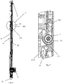
Fig. 6 illustrates a cross-sectional view along a direction of line A-A ofFig. 4 . -
Fig. 7 illustrates an enlarged view of a part C ofFig. 4 . -
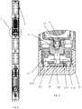
Fig. 8 illustrates a cross-sectional view along a direction of line B-B ofFig. 5 . -
Fig. 9 illustrates an enlarged view of a part D ofFig. 8 . -
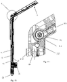
Fig. 10 illustrates a cross-sectional view of the bendable elevating side spray shower of the detailed embodiment when a swing arm is in a folded or bent state. -
Fig. 11 illustrates an enlarged view of a part E ofFig. 10 . -
Fig. 12 illustrates a structural view of the bendable elevating side spray shower of the detailed embodiment in a lifted state. -
Fig. 13 illustrates a structural view of the bendable elevating side spray shower of the detailed embodiment in a lowered state. -
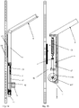
Fig. 14 illustrates a first simplified schematic view of a lifting and lowering gravity balance of the bendable elevating side spray shower of the detailed embodiment. -
Fig. 15 illustrates a second simplified schematic view of the lifting and lowering gravity balance of the bendable elevating side spray shower of the detailed embodiment. -
Fig. 16 illustrates a cross-sectional view of a fixed shaft. -
Fig. 17 illustrates a cross-sectional view of a fixed base. -
Fig. 18 illustrates a cross-sectional view of a rotating member. - Reference numbers: a fixed
member 1, aside sprayer 2, a swing armwater outlet mechanism 3, amatching mechanism 4 and amovable pulley 5; - A
wall base 10, aguide rail 11, n elevatingpart 21, a side spraywater outlet mechanism 22, awater inlet passage 23, aswitching mechanism 24, awater inlet cavity 25, a rotatingmember 31, arotating wheel unit 41, afirst pull rope 42, asecond pull rope 43 and anelastic body 44; a fixedshaft 211, a fixedbase 212, ajoint section 213, apivot hole 311, awater outlet passage 312, awater outlet cavity 313, alarge diameter wheel 411 and asmall diameter wheel 412; awater passage 2121, afirst cavity 2111 and asecond cavity 2131. - Referring to
Figs. 1-18 , a bendable elevating side spray shower comprises a fixedmember 1, aside sprayer 2 connected to the fixed member and configured to lifted and lowered, a swing armwater outlet mechanism 3, amatching mechanism 4 and amovable pulley 5. The swing armwater outlet mechanism 3 is swingably connected to theside sprayer 2 and is configured to swing between a first position in which the swing arm water outlet mechanism is aligned with the side sprayer to define a side spray and a second position in which the swing arm water outlet mechanism is folded or bent relative to the side sprayer. - The
side sprayer 2 comprises an elevatingpart 21 and a side spraywater outlet mechanism 22 connected to the elevating part. Threewater inlet passages 23, a water supply passage and aswitching mechanism 24 are disposed in the elevatingpart 21. Theswitching mechanism 24 is at least connected to the water supply passage and the threewater inlet passages 23 to enable the three water inlet passages to be at least switched (e.g., be at least alternatively switched) to be in communication with the water supply passage, wherein two water inlet passages are respectively in communication with the side spray water outlet mechanism and the swing armwater outlet mechanism 3, and anotherwater inlet passage 23 is disposed on (in) a bottom of the elevatingpart 21 for an external communication from an external water outlet mechanism. Theswitching mechanism 24 comprises an operating member that controls the switching, and the operating member is movably connected to the elevating part, and the switching mechanism adopts, for example, rotation switching, swing switching and the like. - A rotating
member 31 is fixed to an inner end of the swing armwater outlet mechanism 3. The rotatingmember 31 comprises apivot hole 311 and awater outlet passage 312 penetrating an inner side and an outer side of the pivot hole and configured to provide water to the swing armwater outlet mechanism 3. - The
matching mechanism 4 comprises arotating wheel unit 41 rotatably connected to theside sprayer 2, afirst pull rope 42, asecond pull rope 43 and anelastic body 44. Thefirst pull rope 42 is connected to the fixedmember 1 and therotating wheel unit 41 to enable a torque in a first direction to be applied to the rotating wheel unit. Thesecond pull rope 43 is connected to theside sprayer 2 through theelastic body 44, and the second pull rope is further connected to the rotating wheel unit to enable a torque in a second direction to be applied to the rotating wheel unit. The first direction is opposite to the second direction. Therotating wheel unit 41 comprises alarge diameter wheel 411 and asmall diameter wheel 412 coaxially fixed (i.e., coaxially fixed together). Thefirst pull rope 42 is connected to the large diameter wheel, and thesecond pull rope 43 is connected to the small diameter wheel. In a detailed embodiment, thefirst pull rope 42 and thesecond pull rope 43 defines a pull rope, one end of a pull rope is wrapped around the large diameter wheel of the rotating wheel unit and fixed to aguide rail 11 of awall base 10, another end of the pull rope is wrapped around the small diameter wheel of the rotating wheel unit, wrapped the small diameter wheel, and then wrapped around the movable pulley to provide force transmission for gravity balance. The rotating wheel unit is disposed with an integrated structure for the large diameter wheel and the small diameter wheel, the one end of the pull rope is wrapped around the large diameter wheel of the rotating wheel unit, and the another end of the pull rope is wrapped around the small diameter wheel of the rotating wheel unit. The large diameter wheel of the rotating wheel unit rotates, and the small diameter wheel also rotates concurrently to enable the pull rope to be wound. After an up-and-down elevating displacement distance (i.e., a vertical elevating displacement distance) of the shower is converted and reduced, the movable pulley is pulled, and a displacement of the movable pulley is reduced. A degree of expansion and contraction of a tension spring fixed on the movable pulley is further reduced by half due to the movable pulley, a large elevating displacement corresponds to a small degree of spring expansion and contraction. The degree of the spring expansion and contraction is small, and a variation of force value is small. Pull force and gravity force are balanced, and an influence suffered from a variation of elevating height displacement is small. - The
elastic body 44 is connected between themovable pulley 5 and theside sprayer 2. One end of thesecond pull rope 43 is connected to the side sprayer, and another end of thesecond pull rope 43 is wrapped around the movable pulley and connected to the rotating wheel unit. Themovable pulley 5 is fixed to one end of the tension spring to provide tension force transmission. - An upper end of the elevating
part 21 is fixed to two fixedshafts 211 coaxially disposed, the two fixed shafts 211 (i.e., the fixed shafts 211) defines a clearance (e.g., are separated by a clearance) and the clearance defines awater inlet cavity 25 configured to be in communication with the threewater inlet passages 23. The upper end of the elevatingpart 21 is further fixed to a fixedbase 212, the fixed base comprises awater passage 2121 configured to be in communication with the threewater inlet passages 23, the fixedshafts 211 comprise a waterway in communication with the fixedbase 212 and the rotatingmember 31, and the rotatingmember 31 is configured to rotate around a center axis of the fixed shafts, and the rotating member is in communication with the fixed shafts and a water outlet device, configured to rotate around the fixed shafts and fixed to a swing arm (e.g., the swing arm water outlet mechanism 3). Shaft ends of the fixedshafts 211 are concave to definefirst cavities 2111 in communication with thewater inlet cavity 25, the two fixed shafts are fixed to the fixed base, and thewater passage 2121 is in communication with thefirst cavities 2111 of the two fixed shafts. Outer peripheral walls of the fixedshafts 211 further definejoint sections 213, end surfaces of the joint sections are concave to definesecond cavities 2131, thefirst cavities 2111 are in communication with thesecond cavities 2131, and thewater passage 2121 is in communication with the second cavities. Two ports of thepivot hole 311 of the rotatingmember 31 are respectively rotatably and hermetically surround outer sides of the two fixedshafts 211 and an inner port of thewater outlet passage 312 is aligned with the clearance to be in communication with thewater outlet cavity 313. - The
water passage 2121 comprises a water inlet section, a water passage section and two dividing water sections (i.e., dividing water sections). The water passage section is disposed between the water inlet section and the water dividing sections and is in communication with the water inlet section and the water dividing sections. The water inlet section is in communication with thewater inlet passage 23. The two water dividing sections are respectively in communication with thesecond cavities 2131 of the two fixedshafts 211. - The invention may be summarized as follows: The present disclosure discloses a bendable elevating side spray shower, characterized in that: which comprises a fixed member, a side sprayer connected to the fixed member and configured to be lifted and lowered and a swing arm water outlet mechanism, the swing arm water outlet mechanism is swingably connected to the side sprayer and is configured to swing between a first position in which the swing arm water outlet mechanism is aligned with the side sprayer to define a side spray and a second position in which the swing arm water outlet mechanism is bent or folded relative to the side sprayer. It has following advantages: the shower comprises a side arm water discharging, a swing arm water discharging and a hand-held discharging, a rotating shaft is disposed between the side arm water discharging and the swing arm water discharging, the swing arm water discharging can rotate around a rotating shaft to adjust a water discharging angle to meet more showering needs of the user.
- The aforementioned embodiments are merely some embodiments of the present disclosure, and the scope of the disclosure of is not limited thereto. Thus, it is intended that the present disclosure cover any modifications and variations of the presently presented embodiments provided they are made without departing from the appended claims and the specification of the present disclosure.
Claims (14)
- A bendable elevating side spray shower, which comprises a fixed member, a side sprayer connected to the fixed member and configured to be lifted and lowered and a swing arm water outlet mechanism, the swing arm water outlet mechanism is swingably connected to the side sprayer and is configured to swing between a first position in which the swing arm water outlet mechanism is aligned with the side sprayer to define a side spray and a second position in which the swing arm water outlet mechanism is bent or folded relative to the side sprayer.
- The bendable elevating side spray shower according to claim 1, characterized in that: the side sprayer comprises an elevating part and a side spray water outlet mechanism connected to the elevating part, a water inlet passage is disposed in the elevating part, and the water inlet passage is in communication with the side spray water outlet mechanism and the swing arm water outlet mechanism.
- The bendable elevating side spray shower according to claim 1, characterized in that: the side sprayer comprises an elevating part and a side spray water outlet mechanism connected to the elevating part, two water inlet passages are disposed in the elevating part, and the two water inlet passages are respectively in communication with the side spray water outlet mechanism and the swing arm water outlet mechanism.
- The bendable elevating side spray shower according to claim 3, characterized in that: a water supply passage and a switching mechanism are further disposed in the elevating part, and the switching mechanism is at least connected to the water supply passage and the two water inlet passages to enable the two water inlet passages to be at least switched to be in communication with the water supply passage.
- The bendable elevating side spray shower according to claim 3 and/or 4, characterized in that: the elevating part further comprises another water inlet passage, a water supply passage and a switching mechanism is further disposed in the elevating part, and the switching mechanism is connected to the water supply passage and the three water inlet passages to enable the three water inlet passages to be at least switched to be in communication with the water supply passage.
- The bendable elevating side spray shower according to claim 5, characterized in that: the another water inlet passage is disposed on a bottom of the elevating part for an external communication from an external water outlet mechanism.
- The bendable elevating side spray shower according to any one or more of claims 4-6, characterized in that: the switching mechanism comprises an operating member configured to control the switching, and the operating member is movably connected to the elevating part.
- The bendable elevating side spray shower according to any one or more of claims 2-7, characterized in that: an upper end of the elevating part is fixed to two fixed shafts coaxially disposed, and the two fixed shafts define a clearance and the clearance defines a water inlet cavity configured to be in communication with the water inlet passage; an inner end of the swing arm water outlet mechanism is fixed to a rotating member, and the rotating member comprises a pivot hole and a water outlet passage penetrating an inner side and an outer side of the pivot hole and configured to provide water to the swing arm water outlet mechanism; two ports of the pivot hole of the rotating member are respectively rotatably and hermetically surround outer sides the two fixed shafts and an inner port of the water outlet passage is aligned with the clearance to be in communication with the water outlet cavity.
- The bendable elevating side spray shower according to claim 8, characterized in that: an upper end of the elevating part is further fixed to a fixed base, and the fixed base comprises a water passage configured to be in communication with the water inlet passage; shaft ends of the two fixed shafts are concave to define first cavities in communication with the water inlet cavity, the two fixed shafts are fixed to the fixed base, and the water passage is in communication with the first cavities of the two fixed shafts.
- The bendable elevating side spray shower according to claim 9, characterized in that: outer peripheral walls of the two fixed shafts further comprise joint sections, end surfaces of the joint sections are concave to define second cavities, the first cavities are in communication with the second cavities, and the water passage is in communication with the second cavities.
- The bendable elevating side spray shower according to claim 10, characterized in that: the water passage comprises a water inlet section, a water passage section and two water dividing sections, and the water passage section is disposed between the water inlet section and the two water dividing sections and is in communication with the water inlet section and the two water dividing sections, the water inlet section is in communication with the water inlet passage, and the two water dividing sections are respectively in communication with the second cavities of the two fixed shafts.
- The bendable elevating side spray shower according to any one or more of claims 1-11, in particular according to any one or more of claims 1 to 6, which further comprises a matching mechanism, the matching mechanism comprises a rotating wheel unit rotatably connected to the side sprayer, a first pull rope, a second pull rope and an elastic body, the first pull rope is connected to the fixed member and the rotating wheel unit to enable a torque in a first direction to be applied to the rotating wheel unit, the second pull rope is connected to the side sprayer through the elastic body, the second pull rope is further connected to the rotating wheel unit to enable a torque in a second direction to be applied to the rotating wheel unit, and the first direction is opposite to the second direction.
- The bendable elevating side spray shower according to claim 12, which further comprises a movable pulley, the elastic body is connected between the movable pulley and the side sprayer, one end of the second pull rope is connected to the side sprayer, and the other end of the second pull rope wraps the movable pulley and is connected to the rotating wheel unit.
- The bendable elevating side spray shower according to claim 12 and/or 13, characterized in that: the rotating wheel unit comprises a large diameter wheel and a small diameter wheel coaxially fixed, the first pull rope is connected to the large diameter wheel, and the second pull rope is connected to the small diameter wheel.
Applications Claiming Priority (1)
| Application Number | Priority Date | Filing Date | Title |
|---|---|---|---|
| CN202011062734.4A CN114343459A (en) | 2020-09-30 | 2020-09-30 | Side-spraying shower capable of lifting and bending |
Publications (1)
| Publication Number | Publication Date |
|---|---|
| EP3978695A1 true EP3978695A1 (en) | 2022-04-06 |
Family
ID=78332456
Family Applications (1)
| Application Number | Title | Priority Date | Filing Date |
|---|---|---|---|
| EP21200334.7A Pending EP3978695A1 (en) | 2020-09-30 | 2021-09-30 | Bendable elevating side spray shower |
Country Status (2)
| Country | Link |
|---|---|
| EP (1) | EP3978695A1 (en) |
| CN (1) | CN114343459A (en) |
Families Citing this family (1)
| Publication number | Priority date | Publication date | Assignee | Title |
|---|---|---|---|---|
| CN117426689A (en) * | 2022-07-12 | 2024-01-23 | 厦门松霖科技股份有限公司 | shower unit |
Citations (2)
| Publication number | Priority date | Publication date | Assignee | Title |
|---|---|---|---|---|
| DE102011050505A1 (en) * | 2011-02-14 | 2012-08-16 | Markus C. Kopp | Shower head has base body, on whose one side connecting element for receiving water-carrying device is provided, and shower device is formed in two or more parts |
| CN110711649A (en) * | 2019-09-24 | 2020-01-21 | 上海电力大学 | Shower nozzle with adjustable spray mode |
Family Cites Families (9)
| Publication number | Priority date | Publication date | Assignee | Title |
|---|---|---|---|---|
| US4360159A (en) * | 1980-11-03 | 1982-11-23 | Haynes Joseph C | Adjustable shower head |
| CN2885096Y (en) * | 2006-02-07 | 2007-04-04 | 周华松 | Shower set with lifting bar |
| CN103549902A (en) * | 2013-10-25 | 2014-02-05 | 厦门松霖科技有限公司 | Side spraying shower system |
| CN103912040B (en) * | 2014-03-24 | 2015-09-09 | 梁栋河 | Height-adjustable pull-type shower head |
| CN204294390U (en) * | 2014-11-12 | 2015-04-29 | 开平欧标水暖器材有限公司 | A kind of shower column tap with side spray |
| CN104801440A (en) * | 2015-05-05 | 2015-07-29 | 王琪瑄 | Shower head with convenient lifting function |
| GB2549484B (en) * | 2016-04-18 | 2018-05-16 | Redring Xpelair Group Ltd | Adjustable height shower arrangement |
| CN110623574B (en) * | 2019-08-29 | 2024-07-26 | 厦门大白科技有限公司 | Multi-functional diversified shower device and shower system |
| CN211484270U (en) * | 2019-12-12 | 2020-09-15 | 佛山市诚牌卫浴有限公司 | Multifunctional 7-shaped shower screen with temperature display function |
-
2020
- 2020-09-30 CN CN202011062734.4A patent/CN114343459A/en active Pending
-
2021
- 2021-09-30 EP EP21200334.7A patent/EP3978695A1/en active Pending
Patent Citations (2)
| Publication number | Priority date | Publication date | Assignee | Title |
|---|---|---|---|---|
| DE102011050505A1 (en) * | 2011-02-14 | 2012-08-16 | Markus C. Kopp | Shower head has base body, on whose one side connecting element for receiving water-carrying device is provided, and shower device is formed in two or more parts |
| CN110711649A (en) * | 2019-09-24 | 2020-01-21 | 上海电力大学 | Shower nozzle with adjustable spray mode |
Also Published As
| Publication number | Publication date |
|---|---|
| CN114343459A (en) | 2022-04-15 |
Similar Documents
| Publication | Publication Date | Title |
|---|---|---|
| US7155776B2 (en) | Multipurpose hinge apparatus having automatic return function | |
| US20180318853A1 (en) | Outlet device with multilevel rotary massage water | |
| WO2020232843A1 (en) | Spray gun shower | |
| US9132437B2 (en) | Folding clamshell shower | |
| CN111250282A (en) | Double-switch spray gun shower head | |
| CN110623574B (en) | Multi-functional diversified shower device and shower system | |
| JP2024501924A (en) | Blowing structure and fan | |
| CN114343459A (en) | Side-spraying shower capable of lifting and bending | |
| EP4032616B1 (en) | Water outlet device and shower | |
| CN209179115U (en) | A height-adjustable shower screen | |
| CN118577404B (en) | A oscillating massage water outlet device and a side spray device | |
| CN223300188U (en) | Water outlet device for outlet different water in same hole | |
| CN220496650U (en) | Novel spray gun | |
| CN116393271B (en) | Water outlet device | |
| CN216936536U (en) | Shower head | |
| CN204922089U (en) | Rivers device that commutates for message bathtub | |
| WO2023207797A1 (en) | Bathing device | |
| CN216826883U (en) | Four-gear adjustable stainless steel shower head | |
| CN114319531A (en) | Intelligent closestool, intelligent closestool lid and spray gun and shower nozzle thereof | |
| CN212995098U (en) | Wall-hanging hair-dryer rotary fixing device convenient to hair weathers | |
| JPS6112178B2 (en) | ||
| CN205360337U (en) | Water cannon robot is moved forever to simple and easy electricity generation certainly from type of walking | |
| JPH0332309Y2 (en) | ||
| CN116803541B (en) | Shower head | |
| CN212167846U (en) | A water outlet device with adjustable water flow rate |
Legal Events
| Date | Code | Title | Description |
|---|---|---|---|
| PUAI | Public reference made under article 153(3) epc to a published international application that has entered the european phase |
Free format text: ORIGINAL CODE: 0009012 |
|
| STAA | Information on the status of an ep patent application or granted ep patent |
Free format text: STATUS: REQUEST FOR EXAMINATION WAS MADE |
|
| 17P | Request for examination filed |
Effective date: 20211012 |
|
| AK | Designated contracting states |
Kind code of ref document: A1 Designated state(s): AL AT BE BG CH CY CZ DE DK EE ES FI FR GB GR HR HU IE IS IT LI LT LU LV MC MK MT NL NO PL PT RO RS SE SI SK SM TR |
|
| RBV | Designated contracting states (corrected) |
Designated state(s): AL AT BE BG CH CY CZ DE DK EE ES FI FR GB GR HR HU IE IS IT LI LT LU LV MC MK MT NL NO PL PT RO RS SE SI SK SM TR |
|
| STAA | Information on the status of an ep patent application or granted ep patent |
Free format text: STATUS: EXAMINATION IS IN PROGRESS |
|
| 17Q | First examination report despatched |
Effective date: 20240419 |