EP3978667A1 - Frame of loom - Google Patents
Frame of loom Download PDFInfo
- Publication number
- EP3978667A1 EP3978667A1 EP21193829.5A EP21193829A EP3978667A1 EP 3978667 A1 EP3978667 A1 EP 3978667A1 EP 21193829 A EP21193829 A EP 21193829A EP 3978667 A1 EP3978667 A1 EP 3978667A1
- Authority
- EP
- European Patent Office
- Prior art keywords
- frame
- loom
- beam members
- attachment part
- side frames
- Prior art date
- Legal status (The legal status is an assumption and is not a legal conclusion. Google has not performed a legal analysis and makes no representation as to the accuracy of the status listed.)
- Granted
Links
Images


Classifications
-
- D—TEXTILES; PAPER
- D03—WEAVING
- D03D—WOVEN FABRICS; METHODS OF WEAVING; LOOMS
- D03D49/00—Details or constructional features not specially adapted for looms of a particular type
- D03D49/02—Construction of loom framework
-
- D—TEXTILES; PAPER
- D03—WEAVING
- D03D—WOVEN FABRICS; METHODS OF WEAVING; LOOMS
- D03D49/00—Details or constructional features not specially adapted for looms of a particular type
- D03D49/02—Construction of loom framework
- D03D49/027—Arrangements or means for noise reduction
-
- D—TEXTILES; PAPER
- D03—WEAVING
- D03J—AUXILIARY WEAVING APPARATUS; WEAVERS' TOOLS; SHUTTLES
- D03J1/00—Auxiliary apparatus combined with or associated with looms
- D03J1/14—Apparatus for threading warp stop-motion droppers, healds, or reeds
Definitions
- the present invention relates to a frame of a loom including a pair of side frames connected to each other by means of a plurality of beam members attached to attachment parts on inner surfaces of each of the side frames, and each configured to support a heddle frame guide configured to guide up-and-down movement of a heddle frame of an opening device. Further aspects are directed to a frame for a loom, a loom frame, and a loom comprising a frame, as well as the use of a frame for a loom.
- a frame of a general loom is constituted by connecting a pair of side frames by means of a plurality of beam members.
- the frame includes a pair of side frames each having a housing shape, and long beam members are attached to inner surfaces of each of the side frames, so that both the side frames are connected by means of the plurality of beam members.
- the loom also includes a pair of heddle frame guides for guiding up-and-down movement of a heddle frame of an opening device.
- the heddle frame guides are provided on the loom in a form of being supported on each of the side frames of the frame.
- the specification of the loom is defined based on a weaving width of a fabric to be woven.
- the heddle frame mounted on the loom has a width corresponding to the greatest weaving width that can be woven in the loom.
- up-and-down movement of the heddle frame is guided by the pair of heddle frame guides, as described above.
- the heddle frame guides are each supported by means of brackets and the like each attached to the corresponding side frame.
- an interval between the pair of heddle frame guides is defined by positions of both the brackets in a width direction of the loom. Therefore, an interval between both the side frames to which the brackets are attached is set such that the pair of heddle frame guides supported on each of the side frames via the brackets is arranged at an interval at which they can guide the heddle frame as described above. Specifically, the interval between the pair of side frames of the frame is set such that the interval between positions in which the brackets are attached (positions in a warp direction, in which the heddle frame guides are supported) implements arrangement of the heddle frame guides as described above, and is determined based on the interval between the positions in which the brackets are attached taking into consideration a width of the heddle frame.
- the brackets are attached to the inner surfaces of the side frames. Specifically, a position of the side frame in which the bracket is attached is on the inner surface. In addition, the inner surface is substantially planar although there is slight unevenness.
- the present invention has been made in view of the above situations, and an object thereof is to provide a frame of a loom having the frame constituted by both side frames connected by means of a plurality of beam members and capable of improving a vibration-proof characteristic against beating vibrations.
- a preamble of the present invention is a frame of a loom including a pair of side frames connected to each other by means of a plurality of beam members attached to attachment parts on inner surfaces of each of the side frames, and each configured to support a heddle frame guide configured to guide up-and-down movement of a heddle frame of an opening device.
- the present invention is characterized in that at least one of the pair of side frames has, as a reference surface, a part located in a position of the inner surface in which the heddle frame guide in a warp direction is supported and the attachment part to which at least one of the plurality of beam members is attached is formed to be an offset attachment part located on a more inner side of the frame than the reference surface.
- the plurality of beam members may include two winding-side beam members provided in different positions in an upper and lower direction on a further winding-side than the heddle frame guides, and the frame may be configured such that the offset attachment part is the attachment part to which an upper beam member of the winding-side beam members is attached.
- the attachment part to which the target beam member is attached is formed to be an offset attachment part located on a more inner side in the width direction of the loom than the reference surface.
- an interval between a pair of side frames is determined based on an interval between positions in which brackets corresponding to each of the heddle frame guides are attached.
- the attachment part to which the target beam member is attached is formed to be an offset attachment part located on the more inner side than the reference surface. Therefore, when the frame (side frame) is configured in such a way, a length dimension of the target beam member is reduced, as compared to a case where the frame is configured according to the related art.
- the length dimension is reduced in this way, so that the target beam member is difficult to bend in an upper and lower direction and in a front and rear direction of the frame.
- the frame constituted by the side frames connected by means of the beam members is difficult to vibrate in the upper and lower direction and in the front and rear direction, as a whole. That is, the vibration-proof characteristic of the frame is improved. Therefore, according to the frame, even in a state where the beating vibrations as described above occur on the frame having the configuration of the related art, the vibrations of the entire frame are reduced as much as possible, so that the lowering in quality of the woven fabric due to the vibrations can be prevented.
- the target beam member is set as the upper beam member of the two winding-side beam members provided in different positions in the upper and lower direction on the winding-side, i.e., the offset attachment part is set as the attachment part to which the upper beam member is attached, so that the vibration-proof characteristic of the frame can be more effectively improved.
- the support positions of the rocking shaft, which causes the beating vibrations, on the side frame are on the winding-side with respect to the heddle frame guide in the front and rear direction of the frame.
- a winding-side beam member, which is a beam member on the winding side with respect to the heddle frame guide, of the plurality of beam members is shorter in distance from the rocking shaft than a delivery-side beam member, which is a beam member on the delivery side with respect to the heddle frame guide, and is thus susceptible to an influence of the beating vibrations.
- each of the side frames is strongly fixed to a setup surface of the loom by means of anchor bolts.
- the upper beam member of the winding-side beam members which are the beam members susceptible to the influence of the beating vibrations of the plurality of beam members, is set as the target beam member, so that the vibration-proof characteristic of the frame can be more effectively improved.
- FIGS. 1 to 4 an embodiment (the present embodiment) of a frame of a loom to which the present invention is applied will be described with reference to FIGS. 1 to 4 .
- a frame 1 has a configuration where a pair of side frames 2 and 2 is provided as a main body and both the side frames 2 and 2 are connected by means of four beam members 3a, 3b, 3c and 3d.
- each of the side frames 2 has a housing shape having a space therein.
- a warp beam 6 for delivering a warp T is provided on one side in a front and rear direction of the loom in a form of being supported on both the side frames 2 and 2.
- a winding beam 8 for winding a manufactured woven fabric is provided on the other side in the front and rear direction of the loom in a form of being supported on both the side frames 2 and 2.
- the loom has a pair of heddle frame guides 12 and 12 for guiding up-and-down movement of heddle frames 11 of an opening device.
- the heddle frame guides 12 are each provided on the loom in a form of being supported by means of brackets 14 each attached to the corresponding side frame 2.
- the brackets 14 are each fixed to the corresponding side frame 2 in a form of being fixed to an inner surface 9 of the side frame 2.
- each of the brackets 14 is constituted by a plate-shaped support plate 14a attached to the frame and a support shaft 14b attached to the support plate 14a so as to protrude from one end face of the support plate 14a.
- Each of the brackets 14 is fixed to the inner surface 9 of the side frame 2 in such a form that the support shaft 14b is located above an upper surface of the side frame 2 and the support shaft 14b is faced toward an inner side of the loom.
- the support shaft 14b is located at a substantial center of the side frame 2 in the front and rear direction.
- Each of the heddle frame guides 12 is supported on the corresponding side frame 2 via the bracket 14 in a form of being attached to a tip end portion of the support shaft 14b of the bracket 14. Therefore, as for a positional relationship in the width direction between the side frame 2 and the heddle frame guide 12, the heddle frame guide 12 is spaced from the inner surface 9 of the side frame 2 about by the bracket 14.
- the heddle frame guide 12 has two guide portions 12b provided at an interval in an upper and lower direction (vertical direction) in a state where the heddle frame guide 12 is supported on the side frame 2 as described above.
- Each of the guide portions 12b has a plurality of guide grooves for guiding up-and-down movement of a plurality of heddle frames 11 provided for the loom.
- each of the heddle frames 11 is provided with both sides thereof being guided to the guide grooves of the pair of heddle frame guides 12 and 12.
- a position of the guide groove of each of the heddle frame guides 12 is a position in which the heddle frame 11 is guided on a side of each of the side frames 2 of the loom.
- the guide position is defined by a position of the side frame 2 (inner surface 9) due to the positional relationship between the side frame 2 and the heddle frame guide 12 as described above. Therefore, a part (surface) of the inner surface 9 of the side frame 2, to which the bracket 14 is attached, is a reference surface 10 for defining the guide position.
- the specification of the loom is determined based on a weaving width of a fabric W to be woven.
- the heddle frame 11 mounted on the loom has a width corresponding to the specification (the greatest weaving width that can be woven) of the loom. Therefore, an interval between the pair of side frames 2 and 2 configured to support the pair of heddle frame guides 12 and 12 provided so as to guide the heddle frame 11 is set, taking into consideration a width of the heddle frame 11 and the positional relationship between the side frame 2 and the heddle frame guide 12.
- An interval between the pair of the reference surfaces 10 and 10 included in the pair of side frames 2 and 2 whose interval is set in such a way is also defined according to the interval between the side frames 2 and 2.
- the two beam members 3a and 3b are provided as beam members on the winding side (winding-side beam members 3a and 3b) arranged on the winding beam 8-side in the front and rear direction
- the two remaining beam members 3c and 3d are provided as beam members on the delivery side (delivery-side beam members 3c and 3d) arranged on the warp beam 6-side in the front and rear direction.
- the winding-side beam members 3a and 3b are arranged in different positions in the upper and lower direction, the upper beam member 3a is a so-called front top stay, and the lower beam member 3b is a so-called front bottom stay.
- the delivery-side beam members 3c and 3d are also arranged in different positions in the upper and lower direction, the upper beam member 3c is a so-called rear top stay, and the lower beam member 3d is a so-called rear bottom stay.
- the front top stay 3a and the rear top stay 3c each have flanges formed at both end portions thereof.
- the flange is formed with a plurality of through-holes in which bolts for fixing are inserted.
- the bolts for fixing inserted in the through-holes of each of the flanges are inserted into through-holes formed to open to the inner surface 9 of the corresponding side frame 2 and are screwed with nuts, so that the front top stay 3a and the rear top stay 3c are fixed to each of the side frames 2 (inner surfaces 9).
- the front top stay 3a and the rear top stay 3c are fixed to attachment parts, which are attachment parts set on the inner surfaces 9 of each of the side frames 2, thereby connecting both the side frames 2 and 2.
- the front bottom stay 3b and the rear bottom stay 3d are each a beam member having a substantially U-shaped section and each have end walls formed at both end portions so as to close end portions.
- the end wall is formed with a plurality of through-holes in which bolts for fixing are inserted.
- the bolts for fixing inserted in the through-holes of each of the end walls are inserted into through-holes formed to open to the inner surface 9 of the corresponding side frame 2 and are screwed with nuts, so that the front bottom stay 3b and the rear bottom stay 3d are fixed to each of the side frames 2 (inner surfaces 9).
- the front bottom stay 3b and the rear bottom stay 3d are fixed to attachment parts, which are attachment parts set on the inner surfaces 9 of each of the side frames 2, thereby connecting both the side frames 2 and 2.
- a main shaft 16 of the loom is supported at both end portions by both the side frames 2 and 2 in a direction parallel to the front top stay 3a, i.e., a direction parallel to a width direction of the loom (hereinafter, simply referred to as "width direction").
- a support position of the main shaft 16 is a position between the front top stay 3a and the bracket 14 (heddle frame guide 12) in the front and rear direction, and is a position in which an upper end (upper edge) thereof is located near a lower surface of the front top stay 3a, in the upper and lower direction.
- the loom also has a beating mechanism configured to rock a reed 5.
- the reed 5 is supported on a rocking shaft 4 via a plurality of sley swords and the like.
- the rocking shaft 4 is supported at both end portions by both the side frames 2 and 2 in a direction parallel to the width direction.
- a support position of the rocking shaft 4 is substantially the same position as the main shaft 16 in the front and rear direction, and is a position above the main shaft 16 and overlapping the front top stay 3a in the upper and lower direction.
- the loom also has a winding mechanism configured to send the manufactured woven fabric W toward the winding beam 8 at a speed corresponding to a woven fabric density.
- the winding mechanism includes a cloth winding roll 15, and a pair of press rolls 15b and 15b provided to be pressed against the cloth winding roll 15 by means of a pressing mechanism (not shown).
- the cloth winding roll 15 is supported at both end portions by both the side frames 2 and 2 in a direction parallel to the width direction.
- a support position of the cloth winding roll 15 is a position on a side opposite to the main shaft 16 with respect to the front top stay 3a in the front and rear direction, and is a position overlapping the front top stay 3a in the upper and lower direction.
- At least one of the plurality of attachment parts of one or both of the pair of side frames is formed to be an offset attachment part located on a more inner side of the frame 1 than the reference surface 10.
- each of the attachment parts of the front top stay 3a and the rear top stay 3c on both the side frames 2 and 2 is formed as the offset attachment part.
- the inner surface 9 is formed such that a part of a range, which becomes the attachment part for the front top stay 3a as seen in the width direction, protrudes with respect to a part including the reference surface 10 so that the attachment part is located on an inner side of the frame 1 with respect to the reference surface 10.
- the attachment part is located on an inner side of the frame 1 with respect to the reference surface 10 and is formed as an offset attachment part 17 of the present invention.
- the attachment part for the front top stay 3a is formed as the (first) offset attachment part 17.
- the inner surface 9 of each side frame 2 is formed such that a part of a range, which becomes the attachment part for the rear top stay 3c as seen in the width direction, protrudes with respect to the part including the reference surface 10 so that the attachment part is located on an inner side of the frame 1 with respect to the reference surface 10.
- the attachment part is located on an inner side of the frame 1 with respect to the reference surface 10 and is formed as an offset attachment part 18 of the present invention.
- the attachment part for the rear top stay 3c is also formed as the (second) offset attachment part 18.
- the first offset attachment part 17 that is the attachment part for the front top stay 3a is formed over a range wider than a part, to which the front top stay 3a is attached, as seen in the width direction. Specifically, the first offset attachment part 17 is formed over a range including each support position of the main shaft 16, the rocking shaft 4 and the cloth winding roll 15, in addition to the part to which the front top stay 3a is attached.
- an inner sidewall (inner wall) of each side frame 2 is formed with through-holes 23a, 23b and 23c, in which bearings 22a, 22b and 22c for supporting the main shaft 16, the rocking shaft 4 and the cloth winding roll 15 are arranged, at portions corresponding to the first offset attachment part 17.
- Bearing holders 19, 20 and 21 for arranging the bearings 22a, 22b and 22c are each attached to each of the through-holes 23a, 23b and 23c.
- the main shaft 16, the rocking shaft 4 and the cloth winding roll 15 are supported on both the side frames 2 and 2 by means of each of the bearings 22a, 22b and 22c arranged on each of the side frames 2 by the bearing holders 19, 20 and 21.
- the bearing holders 19, 20 and 21 have the same configuration. Therefore, the bearing holder 20 for the rocking shaft 4 is exemplarily described.
- the bearing holder 20 is constituted by a cylindrical fitting/insertion portion 20a having a through-hole 20c, as a main body.
- the bearing holder 20 has a flange portion 20b formed on one end-side of the fitting/insertion portion 20a in an axis line direction.
- the fitting/insertion portion 20a is formed so that an inner diameter of the through-hole 20c is large enough to accommodate the bearing 22b in a fitted state.
- the fitting/insertion portion 20a is formed so that the inner diameter of the through-hole 20c becomes smaller at an end portion on the one end-side.
- the through-hole 20c is formed by a portion (accommodation portion) configured to accommodate the bearing 22b and a small-diameter portion on the one end-side with respect to the accommodation portion. Therefore, the fitting/insertion portion 20a has an end wall 20e, in which the small-diameter portion of the through-hole 20c is formed, at an end portion on one end portion-side.
- An inner diameter of the small-diameter portion of the through-hole 20c formed in the end wall 20e substantially coincides with an outer diameter of a shaft portion of the rocking shaft 4, which is supported by the bearing 22b.
- the flange portion 20b is formed on the one end-side of the fitting/insertion portion 20a, as described above, and is formed to be thicker than a thickness of the end wall 20e of the fitting/insertion portion 20a. Specifically, a thickness of the flange portion 20b is set so that a difference from the thickness of the end wall 20e is about a half of a width of the bearing 22b.
- the flange portion 20b is formed with a plurality of through-holes in which bolts 25 for fixing the bearing holder 20 to the side frame 2 (first offset attachment part 17) are inserted.
- the bearing holder 20 is fixed to the side frame 2 in a state where the fitting/insertion portion 20a is fitted in the through-hole 23b. Therefore, the through-hole 23b is formed so that an inner diameter thereof is sized to correspond to an outer diameter of the fitting/insertion portion 20a.
- the bearing holder 20 is fixed to the side frame 2 by screwing the bolts 25 for fixing inserted in the through-holes of the flange portion 20b into female screw holes formed to open to the corresponding offset attachment part 17.
- the bearing 22b is fitted in the accommodation portion of the through-hole 20c, and is accommodated in the bearing holder 20 in a state where one end-side thereof is in contact with the end wall 20e.
- the bearing 22b is in a state where a center of a width thereof substantially coincides with a position of an end face of the flange portion 20b of the bearing holder 20 facing toward the other end-side, in the axis line direction. Therefore, in the state where the bearing holder 20 is attached to the side frame 2 as described above, the bearing 22b is in the state where the center of the width thereof substantially coincides with a position of the offset attachment part 17 of the side frame 2, in the width direction of the loom.
- a position of the bearing 22b that supports the shaft portion of the rocking shaft 4, i.e., the support position of the rocking shaft 4 is located on a more inner side of the frame 1 in the width direction, as compared to a case where the same bearing holder is attached to the side frame 2 so that the flange portion abuts against the reference surface 10.
- the attachment parts of both the side frames 2 and 2 for the front top stay 3a and the rear top stay 3c are formed to be the offset attachment parts 17 and 18.
- the front top stay 3a and the rear top stay 3c are formed smaller in length dimension, as compared to the frame of the related art where the attachment parts are formed in the same position as the reference surface 10 in the width direction.
- the frame 1 is configured so that the front top stay 3a and the rear top stay 3c are difficult to bend in the upper and lower direction and in the front and rear direction, and is accordingly difficult to vibrate in the upper and lower direction and in the front and rear direction, as a whole, so that the vibration-proof characteristic against the beating vibrations is improved.
- the attachment part for the front top stay 3a is formed to be the offset attachment part 17, and the attachment part to which the upper beam member 3a of the two winding-side beam members 3a and 3b provided in different positions in the upper and lower direction is attached is formed to be the offset attachment part 17.
- the offset attachment part 17 is formed over the part including each support position of the main shaft 16, the rocking shaft 4 and the cloth winding roll 15, as seen in the width direction, in addition to the part to which the front top stay 3a is attached, and each side frame 2 is formed so that parts before and after the attachment part on the inner surface 9 for the front top stay 3a protrude with respect to the part including the reference surface 10.
- each side frame 2 is formed so that the part of the inner wall including the attachment part is difficult to bend in the front and rear direction.
- the offset attachment part 17 is formed so that the protruding amount is the same over the entire offset attachment part so as for the protruding part to be flat, and the protruding amount at the parts before and after the attachment part is the same.
- each side frame 2 is formed so that the part of the inner wall including the attachment part is difficult to bend toward both sides in the front and rear direction. Therefore, since each side frame 2 itself is difficult to bend as described above, the vibration-proof characteristic of the frame 1 is accordingly improved more effectively.
- the attachment part for the rear top stay 3c is formed to be the offset attachment part 18, and the attachment part to which the upper beam member 3c of the two delivery-side beam members 3c and 3d provided in different positions in the upper and lower direction is attached is formed to be the offset attachment part 18. Therefore, the vibration-proof characteristic against beam vibrations of the frame 1 is accordingly improved more effectively.
- the tension variation becomes a vibrating force to cause vibrations on the warp beam 6 in a rotating direction and a pull-out direction (upper and lower direction) of the warp T.
- the beam vibrations act on each side frame 2 on the delivery-side, as the vibrating force, the rear top stay 3c and the rear bottom stay 3d that are the delivery-side beam members are susceptible to the influence of the beam vibrations.
- the vibrations are more likely to occur on the upper part than on the lower part. For this reason, when comparing the two delivery-side beam members provided in different positions in the upper and lower direction, the rear top stay 3c is more susceptible to the influence of the beam vibrations, as compared to the rear bottom stay 3d.
- the frame of a loom of the present invention is not limited to the above embodiment, and can be implemented in following modified embodiments.
- the offset attachment part 17 in the case where the front top stay 3a is formed as the target beam member is formed over the range including each support position of the main shaft 16, the rocking shaft 4 and the cloth winding roll 15, as seen in the width direction, in addition to the part to which the front top stay 3a is attached.
- the offset attachment part in the frame of a loom of the present invention it is sufficient for the offset attachment part to be formed within a range in which at least the target beam member is attached. Therefore, even when the front top stay 3a is formed as the target beam member, as described above, the offset attachment part may be formed over a range of only the part to which the front top stay 3a is attached or may be formed over a range including one or two of the support positions.
- the attachment parts for the front top stay 3a and the rear top stay 3c are formed as the offset attachment parts 17 and 18 of the present invention.
- the upper beam members 3a and 3c of the two beam members 3a and 3b on the winding-side and the two beam members 3c and 3d on the delivery-side are formed as the target beam members, and the attachment parts are formed as the offset attachment parts 17 and 18.
- the frame may also be configured such that at least one beam member of the plurality of beam members connecting both the side frames 2 and 2 is formed as the target beam member and the attachment part for the target beam member is formed as the offset attachment part.
- the frame 1 configured as described in the above embodiment, for example, as for the two beam members 3a and 3b on the winding-side and/or the two beam members 3c and 3d on the delivery-side, instead of the above embodiment where the upper beam members 3a and 3c are formed as the target beam members, the lower beam members 3b and 3d may be formed as the target beam members and the attachment parts therefor may be formed as the offset attachment parts.
- the beam member on one of the winding-side and the delivery-side may be formed as the target beam member and the attachment part may be formed as the offset attachment part.
- all of the beam members 3a, 3b, 3c and 3d of the frame 1 may be formed as the target beam members, and all of the attachment parts thereof may be formed as the offset attachment parts.
- the attachment parts for the target beam members are formed as the offset attachment parts of the present invention.
- both the attachment parts on both sides for the target beam members are formed as the offset attachment parts.
- the frame may also be configured such that only one of both the attachment parts for the target beam members is formed as the offset attachment part.
- the present invention is not limited to the configuration where the attachment parts for all of the target beam members are formed to be the same, like the above embodiment.
- the attachment parts for some of the target beam members may be formed to be different from the attachment part for another target beam member.
- both the attachment parts for one target beam member may be formed as the offset attachment parts, and only one of the attachment parts for the other target beam member may be formed as the offset attachment part.
- the attachment parts becoming the offset attachment parts are not limited to a configuration where all are the attachment parts of the side frame on the same side.
- the offset attachment parts for some of the target beam members may also be formed as the attachment parts of the side frame on an opposite side to the offset attachment parts for the other target beam members.
- the frame 1 of a loom to which the present invention is applied has the configuration where both the side frames 2 and 2 are connected by means of the four beam members 3a, 3b, 3c and 3d.
- a frame may have a configuration where both the side frames are connected by means of the three or less or five or more beam members.
- the present invention can also be applied to the frame of a loom.
Landscapes
- Engineering & Computer Science (AREA)
- Textile Engineering (AREA)
- Looms (AREA)
Abstract
Description
- The present invention relates to a frame of a loom including a pair of side frames connected to each other by means of a plurality of beam members attached to attachment parts on inner surfaces of each of the side frames, and each configured to support a heddle frame guide configured to guide up-and-down movement of a heddle frame of an opening device. Further aspects are directed to a frame for a loom, a loom frame, and a loom comprising a frame, as well as the use of a frame for a loom.
- As disclosed in
PTL 1, for example, a frame of a general loom is constituted by connecting a pair of side frames by means of a plurality of beam members. Specifically, the frame includes a pair of side frames each having a housing shape, and long beam members are attached to inner surfaces of each of the side frames, so that both the side frames are connected by means of the plurality of beam members. - The loom also includes a pair of heddle frame guides for guiding up-and-down movement of a heddle frame of an opening device. The heddle frame guides are provided on the loom in a form of being supported on each of the side frames of the frame.
- Note that, the specification of the loom is defined based on a weaving width of a fabric to be woven. The heddle frame mounted on the loom has a width corresponding to the greatest weaving width that can be woven in the loom. In the loom, up-and-down movement of the heddle frame is guided by the pair of heddle frame guides, as described above. The heddle frame guides are each supported by means of brackets and the like each attached to the corresponding side frame.
- For this reason, an interval between the pair of heddle frame guides is defined by positions of both the brackets in a width direction of the loom. Therefore, an interval between both the side frames to which the brackets are attached is set such that the pair of heddle frame guides supported on each of the side frames via the brackets is arranged at an interval at which they can guide the heddle frame as described above. Specifically, the interval between the pair of side frames of the frame is set such that the interval between positions in which the brackets are attached (positions in a warp direction, in which the heddle frame guides are supported) implements arrangement of the heddle frame guides as described above, and is determined based on the interval between the positions in which the brackets are attached taking into consideration a width of the heddle frame.
- For reference, in most of the looms, the brackets are attached to the inner surfaces of the side frames. Specifically, a position of the side frame in which the bracket is attached is on the inner surface. In addition, the inner surface is substantially planar although there is slight unevenness.
- [PTL 1]
JP2004-084110A - However, in the loom, it is known that severe vibrations (so-called beating vibrations) occur on both the side frames in association with a beating operation during weaving because a rocking shaft for supporting a reed is supported on both the side frames. In the loom, the entire frame of the loom may be caused to severely vibrate as the beating vibrations occur, in some cases. Particularly, in recent years, an operation of the loom tends to increase in speed, and the vibrations become more severe as the operation speed of the loom increases. When the entire frame of the loom is caused to severely vibrate, each device supported on the frame vibrates to badly influence the weaving, so that a quality of the woven fabric to be woven is lowered.
- The present invention has been made in view of the above situations, and an object thereof is to provide a frame of a loom having the frame constituted by both side frames connected by means of a plurality of beam members and capable of improving a vibration-proof characteristic against beating vibrations.
- A preamble of the present invention is a frame of a loom including a pair of side frames connected to each other by means of a plurality of beam members attached to attachment parts on inner surfaces of each of the side frames, and each configured to support a heddle frame guide configured to guide up-and-down movement of a heddle frame of an opening device.
- The present invention is characterized in that at least one of the pair of side frames has, as a reference surface, a part located in a position of the inner surface in which the heddle frame guide in a warp direction is supported and the attachment part to which at least one of the plurality of beam members is attached is formed to be an offset attachment part located on a more inner side of the frame than the reference surface.
- In the frame of a loom according to the present invention, the plurality of beam members may include two winding-side beam members provided in different positions in an upper and lower direction on a further winding-side than the heddle frame guides, and the frame may be configured such that the offset attachment part is the attachment part to which an upper beam member of the winding-side beam members is attached.
- According to the present invention, in the loom having the frame constituted by the pair of side frames connected by means of the plurality of beam members, as for at least one (hereinafter, referred to as "target beam member") of the plurality of beam members, the attachment part to which the target beam member is attached is formed to be an offset attachment part located on a more inner side in the width direction of the loom than the reference surface. Thereby, the frame is improved in terms of the vibration-proof characteristic against beating vibrations. This is more specifically described as follows.
- As described above, as for a frame of a loom, an interval between a pair of side frames is determined based on an interval between positions in which brackets corresponding to each of the heddle frame guides are attached. Further, according to the present invention, as for at least one of the pair of side frames whose interval is determined in such a way, the attachment part to which the target beam member is attached is formed to be an offset attachment part located on the more inner side than the reference surface. Therefore, when the frame (side frame) is configured in such a way, a length dimension of the target beam member is reduced, as compared to a case where the frame is configured according to the related art.
- The length dimension is reduced in this way, so that the target beam member is difficult to bend in an upper and lower direction and in a front and rear direction of the frame. As a result, the frame constituted by the side frames connected by means of the beam members is difficult to vibrate in the upper and lower direction and in the front and rear direction, as a whole. That is, the vibration-proof characteristic of the frame is improved. Therefore, according to the frame, even in a state where the beating vibrations as described above occur on the frame having the configuration of the related art, the vibrations of the entire frame are reduced as much as possible, so that the lowering in quality of the woven fabric due to the vibrations can be prevented.
- Further, in the frame of a loom of the present invention, the target beam member is set as the upper beam member of the two winding-side beam members provided in different positions in the upper and lower direction on the winding-side, i.e., the offset attachment part is set as the attachment part to which the upper beam member is attached, so that the vibration-proof characteristic of the frame can be more effectively improved.
- Specifically, in the general loom, the support positions of the rocking shaft, which causes the beating vibrations, on the side frame are on the winding-side with respect to the heddle frame guide in the front and rear direction of the frame. For this reason, in the front and rear direction, a winding-side beam member, which is a beam member on the winding side with respect to the heddle frame guide, of the plurality of beam members is shorter in distance from the rocking shaft than a delivery-side beam member, which is a beam member on the delivery side with respect to the heddle frame guide, and is thus susceptible to an influence of the beating vibrations. In addition, each of the side frames is strongly fixed to a setup surface of the loom by means of anchor bolts. Therefore, vibrations are more likely to occur on an upper part than a lower part of each of the side frames. For this reason, when comparing the two beam members provided in different positions in the upper and lower direction, the upper beam member is more susceptible to the influence of the beating vibrations than the lower beam member.
- From these things, the upper beam member of the winding-side beam members, which are the beam members susceptible to the influence of the beating vibrations of the plurality of beam members, is set as the target beam member, so that the vibration-proof characteristic of the frame can be more effectively improved.
-
-
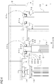
FIG. 1 is a top view of a frame of a loom to which the present invention is applied. -
FIG. 2 is a sectional view taken along an A-A line inFIG. 1 . -
FIG. 3 is a partially enlarged perspective view of the frame of a loom shown inFIG. 1 . -
FIG. 4 is a partially enlarged sectional view of the frame of a loom shown inFIG. 1 . - Hereinafter, an embodiment (the present embodiment) of a frame of a loom to which the present invention is applied will be described with reference to
FIGS. 1 to 4 . - In a loom, a
frame 1 has a configuration where a pair ofside frames side frames side frames 2 has a housing shape having a space therein. Both theside frames - In the loom, a
warp beam 6 for delivering a warp T is provided on one side in a front and rear direction of the loom in a form of being supported on both theside frames winding beam 8 for winding a manufactured woven fabric is provided on the other side in the front and rear direction of the loom in a form of being supported on both theside frames - In addition, the loom has a pair of
heddle frame guides heddle frames 11 of an opening device. Theheddle frame guides 12 are each provided on the loom in a form of being supported by means ofbrackets 14 each attached to thecorresponding side frame 2. Thebrackets 14 are each fixed to thecorresponding side frame 2 in a form of being fixed to aninner surface 9 of theside frame 2. - Note that, each of the
brackets 14 is constituted by a plate-shaped support plate 14a attached to the frame and a support shaft 14b attached to the support plate 14a so as to protrude from one end face of the support plate 14a. Each of thebrackets 14 is fixed to theinner surface 9 of theside frame 2 in such a form that the support shaft 14b is located above an upper surface of theside frame 2 and the support shaft 14b is faced toward an inner side of the loom. As for an attachment position, the support shaft 14b is located at a substantial center of theside frame 2 in the front and rear direction. - Each of the
heddle frame guides 12 is supported on thecorresponding side frame 2 via thebracket 14 in a form of being attached to a tip end portion of the support shaft 14b of thebracket 14. Therefore, as for a positional relationship in the width direction between theside frame 2 and theheddle frame guide 12, theheddle frame guide 12 is spaced from theinner surface 9 of theside frame 2 about by thebracket 14. - The
heddle frame guide 12 has two guide portions 12b provided at an interval in an upper and lower direction (vertical direction) in a state where theheddle frame guide 12 is supported on theside frame 2 as described above. Each of the guide portions 12b has a plurality of guide grooves for guiding up-and-down movement of a plurality of heddle frames 11 provided for the loom. In the loom, each of the heddle frames 11 is provided with both sides thereof being guided to the guide grooves of the pair of heddle frame guides 12 and 12. - In this way, a position of the guide groove of each of the heddle frame guides 12 is a position in which the
heddle frame 11 is guided on a side of each of the side frames 2 of the loom. The guide position is defined by a position of the side frame 2 (inner surface 9) due to the positional relationship between theside frame 2 and the heddle frame guide 12 as described above. Therefore, a part (surface) of theinner surface 9 of theside frame 2, to which thebracket 14 is attached, is areference surface 10 for defining the guide position. - For reference, the specification of the loom is determined based on a weaving width of a fabric W to be woven. The
heddle frame 11 mounted on the loom has a width corresponding to the specification (the greatest weaving width that can be woven) of the loom. Therefore, an interval between the pair of side frames 2 and 2 configured to support the pair of heddle frame guides 12 and 12 provided so as to guide theheddle frame 11 is set, taking into consideration a width of theheddle frame 11 and the positional relationship between theside frame 2 and theheddle frame guide 12. An interval between the pair of the reference surfaces 10 and 10 included in the pair of side frames 2 and 2 whose interval is set in such a way is also defined according to the interval between the side frames 2 and 2. - Further, as for the four beam members connecting the pair of side frames 2 and 2, the two beam members 3a and 3b are provided as beam members on the winding side (winding-side beam members 3a and 3b) arranged on the winding beam 8-side in the front and rear direction, and the two remaining beam members 3c and 3d are provided as beam members on the delivery side (delivery-side beam members 3c and 3d) arranged on the warp beam 6-side in the front and rear direction. The winding-side beam members 3a and 3b are arranged in different positions in the upper and lower direction, the upper beam member 3a is a so-called front top stay, and the lower beam member 3b is a so-called front bottom stay. The delivery-side beam members 3c and 3d are also arranged in different positions in the upper and lower direction, the upper beam member 3c is a so-called rear top stay, and the lower beam member 3d is a so-called rear bottom stay.
- Note that, the front top stay 3a and the rear top stay 3c each have flanges formed at both end portions thereof. The flange is formed with a plurality of through-holes in which bolts for fixing are inserted. The bolts for fixing inserted in the through-holes of each of the flanges are inserted into through-holes formed to open to the
inner surface 9 of thecorresponding side frame 2 and are screwed with nuts, so that the front top stay 3a and the rear top stay 3c are fixed to each of the side frames 2 (inner surfaces 9). In this way, the front top stay 3a and the rear top stay 3c are fixed to attachment parts, which are attachment parts set on theinner surfaces 9 of each of the side frames 2, thereby connecting both the side frames 2 and 2. - The front bottom stay 3b and the rear bottom stay 3d are each a beam member having a substantially U-shaped section and each have end walls formed at both end portions so as to close end portions. The end wall is formed with a plurality of through-holes in which bolts for fixing are inserted. The bolts for fixing inserted in the through-holes of each of the end walls are inserted into through-holes formed to open to the
inner surface 9 of thecorresponding side frame 2 and are screwed with nuts, so that the front bottom stay 3b and the rear bottom stay 3d are fixed to each of the side frames 2 (inner surfaces 9). In this way, the front bottom stay 3b and the rear bottom stay 3d are fixed to attachment parts, which are attachment parts set on theinner surfaces 9 of each of the side frames 2, thereby connecting both the side frames 2 and 2. - A main shaft 16 of the loom is supported at both end portions by both the side frames 2 and 2 in a direction parallel to the front top stay 3a, i.e., a direction parallel to a width direction of the loom (hereinafter, simply referred to as "width direction"). Note that, a support position of the main shaft 16 is a position between the front top stay 3a and the bracket 14 (heddle frame guide 12) in the front and rear direction, and is a position in which an upper end (upper edge) thereof is located near a lower surface of the front top stay 3a, in the upper and lower direction.
- The loom also has a beating mechanism configured to rock a
reed 5. In the beating mechanism, thereed 5 is supported on a rockingshaft 4 via a plurality of sley swords and the like. Further, the rockingshaft 4 is supported at both end portions by both the side frames 2 and 2 in a direction parallel to the width direction. Note that, a support position of the rockingshaft 4 is substantially the same position as the main shaft 16 in the front and rear direction, and is a position above the main shaft 16 and overlapping the front top stay 3a in the upper and lower direction. - The loom also has a winding mechanism configured to send the manufactured woven fabric W toward the winding
beam 8 at a speed corresponding to a woven fabric density. The winding mechanism includes acloth winding roll 15, and a pair of press rolls 15b and 15b provided to be pressed against thecloth winding roll 15 by means of a pressing mechanism (not shown). In addition, thecloth winding roll 15 is supported at both end portions by both the side frames 2 and 2 in a direction parallel to the width direction. Note that, a support position of thecloth winding roll 15 is a position on a side opposite to the main shaft 16 with respect to the front top stay 3a in the front and rear direction, and is a position overlapping the front top stay 3a in the upper and lower direction. - As for the
frame 1 of the loom as described above, according to the present invention, at least one of the plurality of attachment parts of one or both of the pair of side frames is formed to be an offset attachment part located on a more inner side of theframe 1 than thereference surface 10. In the present embodiment, each of the attachment parts of the front top stay 3a and the rear top stay 3c on both the side frames 2 and 2 is formed as the offset attachment part. Theframe 1 of the loom of the present embodiment is specifically described as follows. - As for each of the side frames 2, the
inner surface 9 is formed such that a part of a range, which becomes the attachment part for the front top stay 3a as seen in the width direction, protrudes with respect to a part including thereference surface 10 so that the attachment part is located on an inner side of theframe 1 with respect to thereference surface 10. As a result, the attachment part is located on an inner side of theframe 1 with respect to thereference surface 10 and is formed as an offsetattachment part 17 of the present invention. Specifically, in the present embodiment, the attachment part for the front top stay 3a is formed as the (first) offsetattachment part 17. - As for the
inner surface 9 of eachside frame 2, theinner surface 9 is formed such that a part of a range, which becomes the attachment part for the rear top stay 3c as seen in the width direction, protrudes with respect to the part including thereference surface 10 so that the attachment part is located on an inner side of theframe 1 with respect to thereference surface 10. As a result, the attachment part is located on an inner side of theframe 1 with respect to thereference surface 10 and is formed as an offsetattachment part 18 of the present invention. Specifically, in the present embodiment, the attachment part for the rear top stay 3c is also formed as the (second) offsetattachment part 18. - Note that, in the present embodiment, the first offset
attachment part 17 that is the attachment part for the front top stay 3a is formed over a range wider than a part, to which the front top stay 3a is attached, as seen in the width direction. Specifically, the first offsetattachment part 17 is formed over a range including each support position of the main shaft 16, the rockingshaft 4 and thecloth winding roll 15, in addition to the part to which the front top stay 3a is attached. - Therefore, an inner sidewall (inner wall) of each
side frame 2 is formed with through-holes 23a, 23b and 23c, in which bearings 22a, 22b and 22c for supporting the main shaft 16, the rockingshaft 4 and thecloth winding roll 15 are arranged, at portions corresponding to the first offsetattachment part 17.Bearing holders shaft 4 and thecloth winding roll 15 are supported on both the side frames 2 and 2 by means of each of the bearings 22a, 22b and 22c arranged on each of the side frames 2 by the bearingholders - The bearing
holders holder 20 for the rockingshaft 4 is exemplarily described. The bearingholder 20 is constituted by a cylindrical fitting/insertion portion 20a having a through-hole 20c, as a main body. The bearingholder 20 has a flange portion 20b formed on one end-side of the fitting/insertion portion 20a in an axis line direction. - Note that, as for the fitting/insertion portion 20a, the fitting/insertion portion 20a is formed so that an inner diameter of the through-hole 20c is large enough to accommodate the bearing 22b in a fitted state. However, the fitting/insertion portion 20a is formed so that the inner diameter of the through-hole 20c becomes smaller at an end portion on the one end-side. Specifically, the through-hole 20c is formed by a portion (accommodation portion) configured to accommodate the bearing 22b and a small-diameter portion on the one end-side with respect to the accommodation portion. Therefore, the fitting/insertion portion 20a has an end wall 20e, in which the small-diameter portion of the through-hole 20c is formed, at an end portion on one end portion-side. An inner diameter of the small-diameter portion of the through-hole 20c formed in the end wall 20e substantially coincides with an outer diameter of a shaft portion of the rocking
shaft 4, which is supported by the bearing 22b. - The flange portion 20b is formed on the one end-side of the fitting/insertion portion 20a, as described above, and is formed to be thicker than a thickness of the end wall 20e of the fitting/insertion portion 20a. Specifically, a thickness of the flange portion 20b is set so that a difference from the thickness of the end wall 20e is about a half of a width of the bearing 22b. The flange portion 20b is formed with a plurality of through-holes in which
bolts 25 for fixing the bearingholder 20 to the side frame 2 (first offset attachment part 17) are inserted. - Further, the bearing
holder 20 is fixed to theside frame 2 in a state where the fitting/insertion portion 20a is fitted in the through-hole 23b. Therefore, the through-hole 23b is formed so that an inner diameter thereof is sized to correspond to an outer diameter of the fitting/insertion portion 20a. In addition, the bearingholder 20 is fixed to theside frame 2 by screwing thebolts 25 for fixing inserted in the through-holes of the flange portion 20b into female screw holes formed to open to the corresponding offsetattachment part 17. - The bearing 22b is fitted in the accommodation portion of the through-hole 20c, and is accommodated in the
bearing holder 20 in a state where one end-side thereof is in contact with the end wall 20e. In the accommodated state, the bearing 22b is in a state where a center of a width thereof substantially coincides with a position of an end face of the flange portion 20b of the bearingholder 20 facing toward the other end-side, in the axis line direction. Therefore, in the state where the bearingholder 20 is attached to theside frame 2 as described above, the bearing 22b is in the state where the center of the width thereof substantially coincides with a position of the offsetattachment part 17 of theside frame 2, in the width direction of the loom. Specifically, according to the configuration, a position of the bearing 22b that supports the shaft portion of the rockingshaft 4, i.e., the support position of the rockingshaft 4 is located on a more inner side of theframe 1 in the width direction, as compared to a case where the same bearing holder is attached to theside frame 2 so that the flange portion abuts against thereference surface 10. - As described above, as for the
frame 1 of the loom of the present embodiment, the attachment parts of both the side frames 2 and 2 for the front top stay 3a and the rear top stay 3c are formed to be the offsetattachment parts reference surface 10 in the width direction. Therefore, as compared to the configuration of the related art, theframe 1 is configured so that the front top stay 3a and the rear top stay 3c are difficult to bend in the upper and lower direction and in the front and rear direction, and is accordingly difficult to vibrate in the upper and lower direction and in the front and rear direction, as a whole, so that the vibration-proof characteristic against the beating vibrations is improved. - Further, in the present embodiment, the attachment part for the front top stay 3a is formed to be the offset
attachment part 17, and the attachment part to which the upper beam member 3a of the two winding-side beam members 3a and 3b provided in different positions in the upper and lower direction is attached is formed to be the offsetattachment part 17. In this way, since the front top stay 3a, which is more susceptible to an influence of the beating vibrations, is difficult to bend as described above, the vibration-proof characteristic of theframe 1 is accordingly improved more effectively. - Further, in the present embodiment, in a case where the front top stay 3a is formed as the target beam member, the offset
attachment part 17 is formed over the part including each support position of the main shaft 16, the rockingshaft 4 and thecloth winding roll 15, as seen in the width direction, in addition to the part to which the front top stay 3a is attached, and eachside frame 2 is formed so that parts before and after the attachment part on theinner surface 9 for the front top stay 3a protrude with respect to the part including thereference surface 10. Thereby, as compared to a case where only a part of a range becoming the attachment part as seen in the width direction further protrudes than thereference surface 10, since the dimension of the offsetattachment part 17 in the front and rear direction is larger, eachside frame 2 is formed so that the part of the inner wall including the attachment part is difficult to bend in the front and rear direction. - Further, in the present embodiment, the offset
attachment part 17 is formed so that the protruding amount is the same over the entire offset attachment part so as for the protruding part to be flat, and the protruding amount at the parts before and after the attachment part is the same. Thereby, as compared to a case where even when the parts before and after the attachment part are formed to further protrude than the part including thereference surface 10, the protruding amount at the parts before and after the attachment part is different, eachside frame 2 is formed so that the part of the inner wall including the attachment part is difficult to bend toward both sides in the front and rear direction. Therefore, since eachside frame 2 itself is difficult to bend as described above, the vibration-proof characteristic of theframe 1 is accordingly improved more effectively. - Further, in the present embodiment, the attachment part for the rear top stay 3c is formed to be the offset
attachment part 18, and the attachment part to which the upper beam member 3c of the two delivery-side beam members 3c and 3d provided in different positions in the upper and lower direction is attached is formed to be the offsetattachment part 18. Therefore, the vibration-proof characteristic against beam vibrations of theframe 1 is accordingly improved more effectively. - For reference, as for the beam vibrations, in the loom, it is known that since the tension of the warp T varies due to an opening motion or a beating operation during one cycle of weaving, the tension variation becomes a vibrating force to cause vibrations on the
warp beam 6 in a rotating direction and a pull-out direction (upper and lower direction) of the warp T. Since the beam vibrations act on eachside frame 2 on the delivery-side, as the vibrating force, the rear top stay 3c and the rear bottom stay 3d that are the delivery-side beam members are susceptible to the influence of the beam vibrations. In the meantime, since eachside frame 2 is strongly fixed to the setup surface of the loom by the anchor bolts, the vibrations are more likely to occur on the upper part than on the lower part. For this reason, when comparing the two delivery-side beam members provided in different positions in the upper and lower direction, the rear top stay 3c is more susceptible to the influence of the beam vibrations, as compared to the rear bottom stay 3d. - Although one embodiment of the frame of a loom of the present invention has been described, the frame of a loom of the present invention is not limited to the above embodiment, and can be implemented in following modified embodiments.
- (1) In the above embodiment, as for the offset
attachment part 17 in the case where the front top stay 3a is formed as the target beam member, the offsetattachment part 17 is formed over the range including each support position of the main shaft 16, the rockingshaft 4 and thecloth winding roll 15, as seen in the width direction, in addition to the part to which the front top stay 3a is attached. However, in the frame of a loom of the present invention, it is sufficient for the offset attachment part to be formed within a range in which at least the target beam member is attached. Therefore, even when the front top stay 3a is formed as the target beam member, as described above, the offset attachment part may be formed over a range of only the part to which the front top stay 3a is attached or may be formed over a range including one or two of the support positions. - (2) In the above embodiment, the attachment parts for the front top stay 3a and the rear top stay 3c are formed as the offset
attachment parts attachment parts - Therefore, in the case of the
frame 1 configured as described in the above embodiment, for example, as for the two beam members 3a and 3b on the winding-side and/or the two beam members 3c and 3d on the delivery-side, instead of the above embodiment where the upper beam members 3a and 3c are formed as the target beam members, the lower beam members 3b and 3d may be formed as the target beam members and the attachment parts therefor may be formed as the offset attachment parts. In addition, only the beam member on one of the winding-side and the delivery-side may be formed as the target beam member and the attachment part may be formed as the offset attachment part. Further, all of the beam members 3a, 3b, 3c and 3d of theframe 1 may be formed as the target beam members, and all of the attachment parts thereof may be formed as the offset attachment parts. - (3) In the above embodiment, on both sides of the pair of side frames 2 and 2, the attachment parts for the target beam members are formed as the offset attachment parts of the present invention. Specifically, both the attachment parts on both sides for the target beam members are formed as the offset attachment parts. However, in the frame of a loom of the present invention, the frame may also be configured such that only one of both the attachment parts for the target beam members is formed as the offset attachment part.
- In the case where the two or more beam members are formed as the target beam members, like the above embodiment, the present invention is not limited to the configuration where the attachment parts for all of the target beam members are formed to be the same, like the above embodiment. For example, the attachment parts for some of the target beam members may be formed to be different from the attachment part for another target beam member. For instance, in the case where the two beam members are formed as the target beam members, like the above embodiment, both the attachment parts for one target beam member may be formed as the offset attachment parts, and only one of the attachment parts for the other target beam member may be formed as the offset attachment part.
- In a case where the attachment parts for the two or more target beam members are formed to be the offset attachment parts only on one side, the attachment parts becoming the offset attachment parts are not limited to a configuration where all are the attachment parts of the side frame on the same side. For example, the offset attachment parts for some of the target beam members may also be formed as the attachment parts of the side frame on an opposite side to the offset attachment parts for the other target beam members.
- (4) In the above embodiment, the
frame 1 of a loom to which the present invention is applied has the configuration where both the side frames 2 and 2 are connected by means of the four beam members 3a, 3b, 3c and 3d. However, depending on looms, a frame may have a configuration where both the side frames are connected by means of the three or less or five or more beam members. The present invention can also be applied to the frame of a loom. - Note that, the present invention is not limited to any embodiment described above, and can be changed as appropriate without departing from the gist thereof.
Claims (2)
- A frame (1) of a loom comprising a pair of side frames (2) connected to each other by means of a plurality of beam members (3a, 3b, 3c and 3d) attached to attachment parts on inner surfaces (9) of each of the side frames, and each configured to support a heddle frame guide (12) configured to guide up-and-down movement of a heddle frame (11) of an opening device,
the frame (1) of a loom being characterized in that at least one of the pair of side frames (2 and 2) has, as a reference surface (10), a part located in a position of the inner surface (9) in which the heddle frame guide (12) in a warp direction is supported and the attachment part to which at least one of the plurality of beam members (3a, 3b, 3c and 3d) is attached is formed to be an offset attachment part (17; 18) located on a more inner side of the frame (1) than the reference surface (10). - The frame (1) of a loom according to Claim 1, wherein the plurality of beam members (3a, 3b, 3c and 3d) comprises two winding-side beam members (3a and 3b) provided in different positions in an upper and lower direction on a further winding-side than the heddle frame guide (12), and the offset attachment part (17) is the attachment part to which an upper beam member (3a) of the winding-side beam members (3a and 3b) is attached.
Applications Claiming Priority (1)
| Application Number | Priority Date | Filing Date | Title |
|---|---|---|---|
| JP2020165232A JP7509639B2 (en) | 2020-09-30 | 2020-09-30 | Loom frame |
Publications (2)
| Publication Number | Publication Date |
|---|---|
| EP3978667A1 true EP3978667A1 (en) | 2022-04-06 |
| EP3978667B1 EP3978667B1 (en) | 2023-09-06 |
Family
ID=77864308
Family Applications (1)
| Application Number | Title | Priority Date | Filing Date |
|---|---|---|---|
| EP21193829.5A Active EP3978667B1 (en) | 2020-09-30 | 2021-08-30 | Frame of loom |
Country Status (6)
| Country | Link |
|---|---|
| US (1) | US11566352B2 (en) |
| EP (1) | EP3978667B1 (en) |
| JP (1) | JP7509639B2 (en) |
| KR (1) | KR20220044097A (en) |
| CN (2) | CN215481563U (en) |
| TW (1) | TWI884310B (en) |
Families Citing this family (5)
| Publication number | Priority date | Publication date | Assignee | Title |
|---|---|---|---|---|
| JP7401397B2 (en) * | 2020-06-04 | 2023-12-19 | 津田駒工業株式会社 | loom |
| JP7384747B2 (en) * | 2020-06-04 | 2023-11-21 | 津田駒工業株式会社 | loom |
| JP7477372B2 (en) * | 2020-06-04 | 2024-05-01 | 津田駒工業株式会社 | loom |
| JP7509639B2 (en) * | 2020-09-30 | 2024-07-02 | 津田駒工業株式会社 | Loom frame |
| JP7662402B2 (en) * | 2021-05-06 | 2025-04-15 | 津田駒工業株式会社 | loom |
Citations (3)
| Publication number | Priority date | Publication date | Assignee | Title |
|---|---|---|---|---|
| GB213905A (en) * | 1923-04-04 | 1925-01-08 | Bruyere Banzet & Cie Soc Dauph | Improvements in or connected with the framework of looms for weaving and of other textile machines |
| JP2004084110A (en) | 2002-08-26 | 2004-03-18 | Tsudakoma Corp | Loom frame |
| CN1498996A (en) * | 2002-10-30 | 2004-05-26 | 津田驹工业株式会社 | The frame structure of the loom |
Family Cites Families (16)
| Publication number | Priority date | Publication date | Assignee | Title |
|---|---|---|---|---|
| US644322A (en) * | 1897-06-22 | 1900-02-27 | Philipp Goldschmidt | Lease mechanism. |
| US669394A (en) * | 1900-10-23 | 1901-03-05 | Draper Co | Drawing-in frame. |
| US1191112A (en) * | 1908-03-09 | 1916-07-11 | Barber Colman Co | Warp-drawing machine. |
| US1342896A (en) * | 1917-07-30 | 1920-06-08 | Barber Colman Co | Machine for operating upon warps |
| US2048974A (en) * | 1933-04-05 | 1936-07-28 | Julius W Smith | Means for preparing thread lease |
| US2705022A (en) * | 1951-09-27 | 1955-03-29 | Picanol Jaime | Weaving loom frames and reinforcing cross-members therefor |
| US2911012A (en) * | 1954-12-17 | 1959-11-03 | Rueti Ag Maschf | Variable-depth loom |
| US2835276A (en) * | 1955-03-31 | 1958-05-20 | Yvonne B Hunt | Loom frames |
| BE1008415A6 (en) * | 1994-06-15 | 1996-05-07 | Picanol Nv | WEAVING MACHINE WITH HAIRSTYLES. |
| JP3538137B2 (en) * | 2000-10-23 | 2004-06-14 | 津田駒工業株式会社 | Shedding device in loom |
| JP3968295B2 (en) | 2002-10-30 | 2007-08-29 | 津田駒工業株式会社 | Loom frame structure |
| KR100569200B1 (en) | 2004-05-28 | 2006-04-24 | 김병연 | Fuselage division structure of water jet loom |
| JP4776261B2 (en) * | 2005-04-08 | 2011-09-21 | 津田駒工業株式会社 | Reinforcement structure of hammering device in loom and water jet loom equipped with the same |
| JP5236574B2 (en) * | 2009-05-20 | 2013-07-17 | 株式会社竹中工務店 | Steel structure floor structure system |
| EP3814565B1 (en) * | 2018-06-28 | 2023-11-29 | Picanol | Fabric support |
| JP7509639B2 (en) * | 2020-09-30 | 2024-07-02 | 津田駒工業株式会社 | Loom frame |
-
2020
- 2020-09-30 JP JP2020165232A patent/JP7509639B2/en active Active
-
2021
- 2021-08-24 KR KR1020210111522A patent/KR20220044097A/en active Pending
- 2021-08-24 US US17/410,478 patent/US11566352B2/en active Active
- 2021-08-27 CN CN202122053376.7U patent/CN215481563U/en active Active
- 2021-08-27 CN CN202110995495.6A patent/CN114318633A/en active Pending
- 2021-08-30 EP EP21193829.5A patent/EP3978667B1/en active Active
- 2021-08-31 TW TW110132169A patent/TWI884310B/en active
Patent Citations (3)
| Publication number | Priority date | Publication date | Assignee | Title |
|---|---|---|---|---|
| GB213905A (en) * | 1923-04-04 | 1925-01-08 | Bruyere Banzet & Cie Soc Dauph | Improvements in or connected with the framework of looms for weaving and of other textile machines |
| JP2004084110A (en) | 2002-08-26 | 2004-03-18 | Tsudakoma Corp | Loom frame |
| CN1498996A (en) * | 2002-10-30 | 2004-05-26 | 津田驹工业株式会社 | The frame structure of the loom |
Also Published As
| Publication number | Publication date |
|---|---|
| JP7509639B2 (en) | 2024-07-02 |
| TWI884310B (en) | 2025-05-21 |
| US11566352B2 (en) | 2023-01-31 |
| KR20220044097A (en) | 2022-04-06 |
| US20220098766A1 (en) | 2022-03-31 |
| CN114318633A (en) | 2022-04-12 |
| JP2022057131A (en) | 2022-04-11 |
| EP3978667B1 (en) | 2023-09-06 |
| TW202214927A (en) | 2022-04-16 |
| CN215481563U (en) | 2022-01-11 |
Similar Documents
| Publication | Publication Date | Title |
|---|---|---|
| EP3978667B1 (en) | Frame of loom | |
| EP3978668B1 (en) | Loom | |
| US11608574B2 (en) | Frame structure of loom | |
| US11913144B2 (en) | Loom | |
| JP2022172613A (en) | loom | |
| EP2653595B1 (en) | Air jet loom with a woven cloth supporting apparatus | |
| JP7464497B2 (en) | loom | |
| US5799706A (en) | Weaving loom with vibration damper | |
| CN112543823B (en) | fabric support | |
| CN111020822B (en) | Supporting device for residual warp yarn arrangement rod of loom | |
| EP3967892B1 (en) | Fastener of weaving machine and fixing device for support of the weaving machine | |
| US4997010A (en) | Cloth support with cloth guiding surface for close engagement with reed side walls | |
| US6039088A (en) | Reed assembly with angled dents | |
| JP4367851B2 (en) | Loom equipped with warp regulating member | |
| CN118600626A (en) | A loom with a detachable shock-absorbing yarn frame | |
| JP2019535914A (en) | Device for measuring warp tension in a loom and loom equipped with such a device | |
| JP2001336044A (en) | Reed for weaving machine |
Legal Events
| Date | Code | Title | Description |
|---|---|---|---|
| PUAI | Public reference made under article 153(3) epc to a published international application that has entered the european phase |
Free format text: ORIGINAL CODE: 0009012 |
|
| STAA | Information on the status of an ep patent application or granted ep patent |
Free format text: STATUS: THE APPLICATION HAS BEEN PUBLISHED |
|
| AK | Designated contracting states |
Kind code of ref document: A1 Designated state(s): AL AT BE BG CH CY CZ DE DK EE ES FI FR GB GR HR HU IE IS IT LI LT LU LV MC MK MT NL NO PL PT RO RS SE SI SK SM TR |
|
| STAA | Information on the status of an ep patent application or granted ep patent |
Free format text: STATUS: REQUEST FOR EXAMINATION WAS MADE |
|
| 17P | Request for examination filed |
Effective date: 20220922 |
|
| RBV | Designated contracting states (corrected) |
Designated state(s): AL AT BE BG CH CY CZ DE DK EE ES FI FR GB GR HR HU IE IS IT LI LT LU LV MC MK MT NL NO PL PT RO RS SE SI SK SM TR |
|
| GRAP | Despatch of communication of intention to grant a patent |
Free format text: ORIGINAL CODE: EPIDOSNIGR1 |
|
| STAA | Information on the status of an ep patent application or granted ep patent |
Free format text: STATUS: GRANT OF PATENT IS INTENDED |
|
| RIC1 | Information provided on ipc code assigned before grant |
Ipc: D03D 49/02 20060101AFI20230310BHEP |
|
| INTG | Intention to grant announced |
Effective date: 20230330 |
|
| GRAS | Grant fee paid |
Free format text: ORIGINAL CODE: EPIDOSNIGR3 |
|
| GRAA | (expected) grant |
Free format text: ORIGINAL CODE: 0009210 |
|
| STAA | Information on the status of an ep patent application or granted ep patent |
Free format text: STATUS: THE PATENT HAS BEEN GRANTED |
|
| AK | Designated contracting states |
Kind code of ref document: B1 Designated state(s): AL AT BE BG CH CY CZ DE DK EE ES FI FR GB GR HR HU IE IS IT LI LT LU LV MC MK MT NL NO PL PT RO RS SE SI SK SM TR |
|
| REG | Reference to a national code |
Ref country code: GB Ref legal event code: FG4D |
|
| REG | Reference to a national code |
Ref country code: CH Ref legal event code: EP |
|
| REG | Reference to a national code |
Ref country code: IE Ref legal event code: FG4D |
|
| REG | Reference to a national code |
Ref country code: DE Ref legal event code: R096 Ref document number: 602021004904 Country of ref document: DE |
|
| REG | Reference to a national code |
Ref country code: LT Ref legal event code: MG9D |
|
| REG | Reference to a national code |
Ref country code: NL Ref legal event code: MP Effective date: 20230906 |
|
| PG25 | Lapsed in a contracting state [announced via postgrant information from national office to epo] |
Ref country code: GR Free format text: LAPSE BECAUSE OF FAILURE TO SUBMIT A TRANSLATION OF THE DESCRIPTION OR TO PAY THE FEE WITHIN THE PRESCRIBED TIME-LIMIT Effective date: 20231207 |
|
| PG25 | Lapsed in a contracting state [announced via postgrant information from national office to epo] |
Ref country code: SE Free format text: LAPSE BECAUSE OF FAILURE TO SUBMIT A TRANSLATION OF THE DESCRIPTION OR TO PAY THE FEE WITHIN THE PRESCRIBED TIME-LIMIT Effective date: 20230906 Ref country code: RS Free format text: LAPSE BECAUSE OF FAILURE TO SUBMIT A TRANSLATION OF THE DESCRIPTION OR TO PAY THE FEE WITHIN THE PRESCRIBED TIME-LIMIT Effective date: 20230906 Ref country code: NO Free format text: LAPSE BECAUSE OF FAILURE TO SUBMIT A TRANSLATION OF THE DESCRIPTION OR TO PAY THE FEE WITHIN THE PRESCRIBED TIME-LIMIT Effective date: 20231206 Ref country code: LV Free format text: LAPSE BECAUSE OF FAILURE TO SUBMIT A TRANSLATION OF THE DESCRIPTION OR TO PAY THE FEE WITHIN THE PRESCRIBED TIME-LIMIT Effective date: 20230906 Ref country code: LT Free format text: LAPSE BECAUSE OF FAILURE TO SUBMIT A TRANSLATION OF THE DESCRIPTION OR TO PAY THE FEE WITHIN THE PRESCRIBED TIME-LIMIT Effective date: 20230906 Ref country code: HR Free format text: LAPSE BECAUSE OF FAILURE TO SUBMIT A TRANSLATION OF THE DESCRIPTION OR TO PAY THE FEE WITHIN THE PRESCRIBED TIME-LIMIT Effective date: 20230906 Ref country code: GR Free format text: LAPSE BECAUSE OF FAILURE TO SUBMIT A TRANSLATION OF THE DESCRIPTION OR TO PAY THE FEE WITHIN THE PRESCRIBED TIME-LIMIT Effective date: 20231207 Ref country code: FI Free format text: LAPSE BECAUSE OF FAILURE TO SUBMIT A TRANSLATION OF THE DESCRIPTION OR TO PAY THE FEE WITHIN THE PRESCRIBED TIME-LIMIT Effective date: 20230906 |
|
| REG | Reference to a national code |
Ref country code: AT Ref legal event code: MK05 Ref document number: 1608675 Country of ref document: AT Kind code of ref document: T Effective date: 20230906 |
|
| PG25 | Lapsed in a contracting state [announced via postgrant information from national office to epo] |
Ref country code: NL Free format text: LAPSE BECAUSE OF FAILURE TO SUBMIT A TRANSLATION OF THE DESCRIPTION OR TO PAY THE FEE WITHIN THE PRESCRIBED TIME-LIMIT Effective date: 20230906 |
|
| PG25 | Lapsed in a contracting state [announced via postgrant information from national office to epo] |
Ref country code: IS Free format text: LAPSE BECAUSE OF FAILURE TO SUBMIT A TRANSLATION OF THE DESCRIPTION OR TO PAY THE FEE WITHIN THE PRESCRIBED TIME-LIMIT Effective date: 20240106 |
|
| PG25 | Lapsed in a contracting state [announced via postgrant information from national office to epo] |
Ref country code: AT Free format text: LAPSE BECAUSE OF FAILURE TO SUBMIT A TRANSLATION OF THE DESCRIPTION OR TO PAY THE FEE WITHIN THE PRESCRIBED TIME-LIMIT Effective date: 20230906 |
|
| PG25 | Lapsed in a contracting state [announced via postgrant information from national office to epo] |
Ref country code: ES Free format text: LAPSE BECAUSE OF FAILURE TO SUBMIT A TRANSLATION OF THE DESCRIPTION OR TO PAY THE FEE WITHIN THE PRESCRIBED TIME-LIMIT Effective date: 20230906 |
|
| PG25 | Lapsed in a contracting state [announced via postgrant information from national office to epo] |
Ref country code: SM Free format text: LAPSE BECAUSE OF FAILURE TO SUBMIT A TRANSLATION OF THE DESCRIPTION OR TO PAY THE FEE WITHIN THE PRESCRIBED TIME-LIMIT Effective date: 20230906 Ref country code: RO Free format text: LAPSE BECAUSE OF FAILURE TO SUBMIT A TRANSLATION OF THE DESCRIPTION OR TO PAY THE FEE WITHIN THE PRESCRIBED TIME-LIMIT Effective date: 20230906 Ref country code: IS Free format text: LAPSE BECAUSE OF FAILURE TO SUBMIT A TRANSLATION OF THE DESCRIPTION OR TO PAY THE FEE WITHIN THE PRESCRIBED TIME-LIMIT Effective date: 20240106 Ref country code: ES Free format text: LAPSE BECAUSE OF FAILURE TO SUBMIT A TRANSLATION OF THE DESCRIPTION OR TO PAY THE FEE WITHIN THE PRESCRIBED TIME-LIMIT Effective date: 20230906 Ref country code: EE Free format text: LAPSE BECAUSE OF FAILURE TO SUBMIT A TRANSLATION OF THE DESCRIPTION OR TO PAY THE FEE WITHIN THE PRESCRIBED TIME-LIMIT Effective date: 20230906 Ref country code: CZ Free format text: LAPSE BECAUSE OF FAILURE TO SUBMIT A TRANSLATION OF THE DESCRIPTION OR TO PAY THE FEE WITHIN THE PRESCRIBED TIME-LIMIT Effective date: 20230906 Ref country code: AT Free format text: LAPSE BECAUSE OF FAILURE TO SUBMIT A TRANSLATION OF THE DESCRIPTION OR TO PAY THE FEE WITHIN THE PRESCRIBED TIME-LIMIT Effective date: 20230906 Ref country code: SK Free format text: LAPSE BECAUSE OF FAILURE TO SUBMIT A TRANSLATION OF THE DESCRIPTION OR TO PAY THE FEE WITHIN THE PRESCRIBED TIME-LIMIT Effective date: 20230906 Ref country code: PT Free format text: LAPSE BECAUSE OF FAILURE TO SUBMIT A TRANSLATION OF THE DESCRIPTION OR TO PAY THE FEE WITHIN THE PRESCRIBED TIME-LIMIT Effective date: 20240108 |
|
| PG25 | Lapsed in a contracting state [announced via postgrant information from national office to epo] |
Ref country code: PL Free format text: LAPSE BECAUSE OF FAILURE TO SUBMIT A TRANSLATION OF THE DESCRIPTION OR TO PAY THE FEE WITHIN THE PRESCRIBED TIME-LIMIT Effective date: 20230906 |
|
| REG | Reference to a national code |
Ref country code: DE Ref legal event code: R097 Ref document number: 602021004904 Country of ref document: DE |
|
| PG25 | Lapsed in a contracting state [announced via postgrant information from national office to epo] |
Ref country code: DK Free format text: LAPSE BECAUSE OF FAILURE TO SUBMIT A TRANSLATION OF THE DESCRIPTION OR TO PAY THE FEE WITHIN THE PRESCRIBED TIME-LIMIT Effective date: 20230906 |
|
| PLBE | No opposition filed within time limit |
Free format text: ORIGINAL CODE: 0009261 |
|
| STAA | Information on the status of an ep patent application or granted ep patent |
Free format text: STATUS: NO OPPOSITION FILED WITHIN TIME LIMIT |
|
| PG25 | Lapsed in a contracting state [announced via postgrant information from national office to epo] |
Ref country code: DK Free format text: LAPSE BECAUSE OF FAILURE TO SUBMIT A TRANSLATION OF THE DESCRIPTION OR TO PAY THE FEE WITHIN THE PRESCRIBED TIME-LIMIT Effective date: 20230906 Ref country code: SI Free format text: LAPSE BECAUSE OF FAILURE TO SUBMIT A TRANSLATION OF THE DESCRIPTION OR TO PAY THE FEE WITHIN THE PRESCRIBED TIME-LIMIT Effective date: 20230906 |
|
| 26N | No opposition filed |
Effective date: 20240607 |
|
| PG25 | Lapsed in a contracting state [announced via postgrant information from national office to epo] |
Ref country code: BG Free format text: LAPSE BECAUSE OF FAILURE TO SUBMIT A TRANSLATION OF THE DESCRIPTION OR TO PAY THE FEE WITHIN THE PRESCRIBED TIME-LIMIT Effective date: 20230906 |
|
| PG25 | Lapsed in a contracting state [announced via postgrant information from national office to epo] |
Ref country code: BG Free format text: LAPSE BECAUSE OF FAILURE TO SUBMIT A TRANSLATION OF THE DESCRIPTION OR TO PAY THE FEE WITHIN THE PRESCRIBED TIME-LIMIT Effective date: 20230906 |
|
| REG | Reference to a national code |
Ref country code: CH Ref legal event code: PL |
|
| PG25 | Lapsed in a contracting state [announced via postgrant information from national office to epo] |
Ref country code: LU Free format text: LAPSE BECAUSE OF NON-PAYMENT OF DUE FEES Effective date: 20240830 |
|
| PG25 | Lapsed in a contracting state [announced via postgrant information from national office to epo] |
Ref country code: CH Free format text: LAPSE BECAUSE OF NON-PAYMENT OF DUE FEES Effective date: 20240831 Ref country code: MC Free format text: LAPSE BECAUSE OF FAILURE TO SUBMIT A TRANSLATION OF THE DESCRIPTION OR TO PAY THE FEE WITHIN THE PRESCRIBED TIME-LIMIT Effective date: 20230906 |
|
| PG25 | Lapsed in a contracting state [announced via postgrant information from national office to epo] |
Ref country code: FR Free format text: LAPSE BECAUSE OF NON-PAYMENT OF DUE FEES Effective date: 20240831 |
|
| PG25 | Lapsed in a contracting state [announced via postgrant information from national office to epo] |
Ref country code: IE Free format text: LAPSE BECAUSE OF NON-PAYMENT OF DUE FEES Effective date: 20240830 |
|
| PGFP | Annual fee paid to national office [announced via postgrant information from national office to epo] |
Ref country code: DE Payment date: 20250702 Year of fee payment: 5 |
|
| PGFP | Annual fee paid to national office [announced via postgrant information from national office to epo] |
Ref country code: IT Payment date: 20250722 Year of fee payment: 5 |
|
| PGFP | Annual fee paid to national office [announced via postgrant information from national office to epo] |
Ref country code: BE Payment date: 20250703 Year of fee payment: 5 |
|
| PG25 | Lapsed in a contracting state [announced via postgrant information from national office to epo] |
Ref country code: CY Free format text: LAPSE BECAUSE OF FAILURE TO SUBMIT A TRANSLATION OF THE DESCRIPTION OR TO PAY THE FEE WITHIN THE PRESCRIBED TIME-LIMIT; INVALID AB INITIO Effective date: 20210830 |
|
| PG25 | Lapsed in a contracting state [announced via postgrant information from national office to epo] |
Ref country code: HU Free format text: LAPSE BECAUSE OF FAILURE TO SUBMIT A TRANSLATION OF THE DESCRIPTION OR TO PAY THE FEE WITHIN THE PRESCRIBED TIME-LIMIT; INVALID AB INITIO Effective date: 20210830 |
|
| GBPC | Gb: european patent ceased through non-payment of renewal fee |
Effective date: 20250830 |