EP3978652A1 - Electrochemical cell and hydrogen generation method - Google Patents
Electrochemical cell and hydrogen generation method Download PDFInfo
- Publication number
- EP3978652A1 EP3978652A1 EP20814181.2A EP20814181A EP3978652A1 EP 3978652 A1 EP3978652 A1 EP 3978652A1 EP 20814181 A EP20814181 A EP 20814181A EP 3978652 A1 EP3978652 A1 EP 3978652A1
- Authority
- EP
- European Patent Office
- Prior art keywords
- cell
- electrode
- hydrogen
- electrochemical cell
- electrochemical
- Prior art date
- Legal status (The legal status is an assumption and is not a legal conclusion. Google has not performed a legal analysis and makes no representation as to the accuracy of the status listed.)
- Granted
Links
Images




Classifications
-
- C—CHEMISTRY; METALLURGY
- C01—INORGANIC CHEMISTRY
- C01B—NON-METALLIC ELEMENTS; COMPOUNDS THEREOF; METALLOIDS OR COMPOUNDS THEREOF NOT COVERED BY SUBCLASS C01C
- C01B3/00—Hydrogen; Gaseous mixtures containing hydrogen; Separation of hydrogen from mixtures containing it; Purification of hydrogen; Reversible storage of hydrogen
- C01B3/02—Production of hydrogen; Production of gaseous mixtures containing hydrogen
- C01B3/22—Production of hydrogen; Production of gaseous mixtures containing hydrogen by decomposition of gaseous or liquid organic compounds
- C01B3/24—Production of hydrogen; Production of gaseous mixtures containing hydrogen by decomposition of gaseous or liquid organic compounds of hydrocarbons
- C01B3/26—Production of hydrogen; Production of gaseous mixtures containing hydrogen by decomposition of gaseous or liquid organic compounds of hydrocarbons using catalysts
-
- C—CHEMISTRY; METALLURGY
- C25—ELECTROLYTIC OR ELECTROPHORETIC PROCESSES; APPARATUS THEREFOR
- C25B—ELECTROLYTIC OR ELECTROPHORETIC PROCESSES FOR THE PRODUCTION OF COMPOUNDS OR NON-METALS; APPARATUS THEREFOR
- C25B1/00—Electrolytic production of inorganic compounds or non-metals
- C25B1/01—Products
- C25B1/02—Hydrogen or oxygen
- C25B1/04—Hydrogen or oxygen by electrolysis of water
- C25B1/042—Hydrogen or oxygen by electrolysis of water by electrolysis of steam
-
- C—CHEMISTRY; METALLURGY
- C25—ELECTROLYTIC OR ELECTROPHORETIC PROCESSES; APPARATUS THEREFOR
- C25B—ELECTROLYTIC OR ELECTROPHORETIC PROCESSES FOR THE PRODUCTION OF COMPOUNDS OR NON-METALS; APPARATUS THEREFOR
- C25B1/00—Electrolytic production of inorganic compounds or non-metals
- C25B1/01—Products
- C25B1/02—Hydrogen or oxygen
- C25B1/04—Hydrogen or oxygen by electrolysis of water
- C25B1/044—Hydrogen or oxygen by electrolysis of water producing mixed hydrogen and oxygen gas, e.g. Brown's gas [HHO]
-
- C—CHEMISTRY; METALLURGY
- C25—ELECTROLYTIC OR ELECTROPHORETIC PROCESSES; APPARATUS THEREFOR
- C25B—ELECTROLYTIC OR ELECTROPHORETIC PROCESSES FOR THE PRODUCTION OF COMPOUNDS OR NON-METALS; APPARATUS THEREFOR
- C25B15/00—Operating or servicing cells
- C25B15/08—Supplying or removing reactants or electrolytes; Regeneration of electrolytes
- C25B15/083—Separating products
-
- C—CHEMISTRY; METALLURGY
- C25—ELECTROLYTIC OR ELECTROPHORETIC PROCESSES; APPARATUS THEREFOR
- C25B—ELECTROLYTIC OR ELECTROPHORETIC PROCESSES FOR THE PRODUCTION OF COMPOUNDS OR NON-METALS; APPARATUS THEREFOR
- C25B9/00—Cells or assemblies of cells; Constructional parts of cells; Assemblies of constructional parts, e.g. electrode-diaphragm assemblies; Process-related cell features
- C25B9/17—Cells comprising dimensionally-stable non-movable electrodes; Assemblies of constructional parts thereof
- C25B9/19—Cells comprising dimensionally-stable non-movable electrodes; Assemblies of constructional parts thereof with diaphragms
- C25B9/23—Cells comprising dimensionally-stable non-movable electrodes; Assemblies of constructional parts thereof with diaphragms comprising ion-exchange membranes in or on which electrode material is embedded
-
- C—CHEMISTRY; METALLURGY
- C25—ELECTROLYTIC OR ELECTROPHORETIC PROCESSES; APPARATUS THEREFOR
- C25B—ELECTROLYTIC OR ELECTROPHORETIC PROCESSES FOR THE PRODUCTION OF COMPOUNDS OR NON-METALS; APPARATUS THEREFOR
- C25B9/00—Cells or assemblies of cells; Constructional parts of cells; Assemblies of constructional parts, e.g. electrode-diaphragm assemblies; Process-related cell features
- C25B9/70—Assemblies comprising two or more cells
-
- C—CHEMISTRY; METALLURGY
- C25—ELECTROLYTIC OR ELECTROPHORETIC PROCESSES; APPARATUS THEREFOR
- C25B—ELECTROLYTIC OR ELECTROPHORETIC PROCESSES FOR THE PRODUCTION OF COMPOUNDS OR NON-METALS; APPARATUS THEREFOR
- C25B9/00—Cells or assemblies of cells; Constructional parts of cells; Assemblies of constructional parts, e.g. electrode-diaphragm assemblies; Process-related cell features
- C25B9/70—Assemblies comprising two or more cells
- C25B9/73—Assemblies comprising two or more cells of the filter-press type
- C25B9/75—Assemblies comprising two or more cells of the filter-press type having bipolar electrodes
-
- C—CHEMISTRY; METALLURGY
- C25—ELECTROLYTIC OR ELECTROPHORETIC PROCESSES; APPARATUS THEREFOR
- C25B—ELECTROLYTIC OR ELECTROPHORETIC PROCESSES FOR THE PRODUCTION OF COMPOUNDS OR NON-METALS; APPARATUS THEREFOR
- C25B9/00—Cells or assemblies of cells; Constructional parts of cells; Assemblies of constructional parts, e.g. electrode-diaphragm assemblies; Process-related cell features
- C25B9/70—Assemblies comprising two or more cells
- C25B9/73—Assemblies comprising two or more cells of the filter-press type
- C25B9/77—Assemblies comprising two or more cells of the filter-press type having diaphragms
-
- H—ELECTRICITY
- H01—ELECTRIC ELEMENTS
- H01M—PROCESSES OR MEANS, e.g. BATTERIES, FOR THE DIRECT CONVERSION OF CHEMICAL ENERGY INTO ELECTRICAL ENERGY
- H01M4/00—Electrodes
- H01M4/86—Inert electrodes with catalytic activity, e.g. for fuel cells
- H01M4/90—Selection of catalytic material
- H01M4/9016—Oxides, hydroxides or oxygenated metallic salts
- H01M4/9025—Oxides specially used in fuel cell operating at high temperature, e.g. SOFC
- H01M4/9033—Complex oxides, optionally doped, of the type M1MeO3, M1 being an alkaline earth metal or a rare earth, Me being a metal, e.g. perovskites
-
- H—ELECTRICITY
- H01—ELECTRIC ELEMENTS
- H01M—PROCESSES OR MEANS, e.g. BATTERIES, FOR THE DIRECT CONVERSION OF CHEMICAL ENERGY INTO ELECTRICAL ENERGY
- H01M8/00—Fuel cells; Manufacture thereof
- H01M8/10—Fuel cells with solid electrolytes
- H01M8/12—Fuel cells with solid electrolytes operating at high temperature, e.g. with stabilised ZrO2 electrolyte
- H01M8/124—Fuel cells with solid electrolytes operating at high temperature, e.g. with stabilised ZrO2 electrolyte characterised by the process of manufacturing or by the material of the electrolyte
- H01M8/1246—Fuel cells with solid electrolytes operating at high temperature, e.g. with stabilised ZrO2 electrolyte characterised by the process of manufacturing or by the material of the electrolyte the electrolyte consisting of oxides
- H01M8/1253—Fuel cells with solid electrolytes operating at high temperature, e.g. with stabilised ZrO2 electrolyte characterised by the process of manufacturing or by the material of the electrolyte the electrolyte consisting of oxides the electrolyte containing zirconium oxide
-
- C—CHEMISTRY; METALLURGY
- C25—ELECTROLYTIC OR ELECTROPHORETIC PROCESSES; APPARATUS THEREFOR
- C25B—ELECTROLYTIC OR ELECTROPHORETIC PROCESSES FOR THE PRODUCTION OF COMPOUNDS OR NON-METALS; APPARATUS THEREFOR
- C25B15/00—Operating or servicing cells
- C25B15/02—Process control or regulation
-
- H—ELECTRICITY
- H01—ELECTRIC ELEMENTS
- H01M—PROCESSES OR MEANS, e.g. BATTERIES, FOR THE DIRECT CONVERSION OF CHEMICAL ENERGY INTO ELECTRICAL ENERGY
- H01M8/00—Fuel cells; Manufacture thereof
- H01M8/10—Fuel cells with solid electrolytes
- H01M8/12—Fuel cells with solid electrolytes operating at high temperature, e.g. with stabilised ZrO2 electrolyte
- H01M2008/1293—Fuel cells with solid oxide electrolytes
-
- Y—GENERAL TAGGING OF NEW TECHNOLOGICAL DEVELOPMENTS; GENERAL TAGGING OF CROSS-SECTIONAL TECHNOLOGIES SPANNING OVER SEVERAL SECTIONS OF THE IPC; TECHNICAL SUBJECTS COVERED BY FORMER USPC CROSS-REFERENCE ART COLLECTIONS [XRACs] AND DIGESTS
- Y02—TECHNOLOGIES OR APPLICATIONS FOR MITIGATION OR ADAPTATION AGAINST CLIMATE CHANGE
- Y02E—REDUCTION OF GREENHOUSE GAS [GHG] EMISSIONS, RELATED TO ENERGY GENERATION, TRANSMISSION OR DISTRIBUTION
- Y02E60/00—Enabling technologies; Technologies with a potential or indirect contribution to GHG emissions mitigation
- Y02E60/30—Hydrogen technology
- Y02E60/36—Hydrogen production from non-carbon containing sources, e.g. by water electrolysis
-
- Y—GENERAL TAGGING OF NEW TECHNOLOGICAL DEVELOPMENTS; GENERAL TAGGING OF CROSS-SECTIONAL TECHNOLOGIES SPANNING OVER SEVERAL SECTIONS OF THE IPC; TECHNICAL SUBJECTS COVERED BY FORMER USPC CROSS-REFERENCE ART COLLECTIONS [XRACs] AND DIGESTS
- Y02—TECHNOLOGIES OR APPLICATIONS FOR MITIGATION OR ADAPTATION AGAINST CLIMATE CHANGE
- Y02E—REDUCTION OF GREENHOUSE GAS [GHG] EMISSIONS, RELATED TO ENERGY GENERATION, TRANSMISSION OR DISTRIBUTION
- Y02E60/00—Enabling technologies; Technologies with a potential or indirect contribution to GHG emissions mitigation
- Y02E60/30—Hydrogen technology
- Y02E60/50—Fuel cells
-
- Y—GENERAL TAGGING OF NEW TECHNOLOGICAL DEVELOPMENTS; GENERAL TAGGING OF CROSS-SECTIONAL TECHNOLOGIES SPANNING OVER SEVERAL SECTIONS OF THE IPC; TECHNICAL SUBJECTS COVERED BY FORMER USPC CROSS-REFERENCE ART COLLECTIONS [XRACs] AND DIGESTS
- Y02—TECHNOLOGIES OR APPLICATIONS FOR MITIGATION OR ADAPTATION AGAINST CLIMATE CHANGE
- Y02P—CLIMATE CHANGE MITIGATION TECHNOLOGIES IN THE PRODUCTION OR PROCESSING OF GOODS
- Y02P70/00—Climate change mitigation technologies in the production process for final industrial or consumer products
- Y02P70/50—Manufacturing or production processes characterised by the final manufactured product
Definitions
- the electrochemical cell according to the second aspect may be such that, for example, a downstream end of the gas path is closed. This configuration maximizes water vapor utilization efficiency.
- the electrochemical cell according to the seventh aspect may be such that, for example, , hydrogen is generated at the first electrode, hydrogen is generated at the second electrode, hydrogen is converted to protons at the third electrode, and hydrogen is generated at the fourth electrode.
- This configuration enables the production of highly concentrated hydrogen.
- the first electrode 12 includes a catalyst for promoting an electrochemical oxidation reaction of the water vapor.
- the catalyst may be a metal, such as Ni.
- the first electrode 12 may be made of a cermet.
- the cermet is a mixture of a metal and a ceramic material. Examples of the cermet include Ni-YSZ and a mixture of Ni and a ceria-based oxide.
- an expected effect is an increase in the reactive active sites for oxidizing water vapor.
- the first electrode 12 may be a porous body so as to facilitate the diffusion of water vapor.
- the power source 4 is turned on to supply water vapor to the gas path 3.
- the water vapor reaches a surface of the first cell 1
- the water vapor is reduced to hydrogen and oxide ions at the first electrode 12.
- the water vapor is reduced to hydrogen and oxide ions at or near an interface between the first electrolyte layer 11 and the first electrode 12.
- the oxide ions migrate through the first electrolyte layer 11 to reach the second electrode 13.
- an oxidation reaction of the oxide ions occurs, which generates oxygen.
- the oxide ions are oxidized and converted to oxygen at or near an interface between the first electrolyte layer 11 and the second electrode 13.
- the oxygen is discharged from the second electrode 13 and directed to the outside of the electrochemical cell 100 through the oxygen passage 5.
- the hydrogen generated at the surface of the first cell 1 diffuses through the gas path 3 to reach a surface of the second cell 2.
- the hydrogen is oxidized and converted to protons at the third electrode 22.
- the hydrogen is oxidized and converted to protons at or near an interface between the second electrolyte layer 21 and the third electrode 22.
- the protons migrate through the second electrolyte layer 21 to reach the fourth electrode 23.
- a reduction reaction of the protons occurs, which generates hydrogen.
- the protons are reduced and converted to hydrogen at or near an interface between the second electrolyte layer 21 and the fourth electrode 23.
- the hydrogen is directed to the outside of the electrochemical cell 100 through the hydrogen passage 6. Based on the reactions described above, only the hydrogen generated by the reaction at or near the interface between the second electrolyte layer 21 and the fourth electrode 23 is supplied to the outside of the electrochemical cell 100. Accordingly, highly concentrated hydrogen can be obtained.
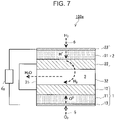
- Fig. 7 illustrates a cross section of an electrochemical cell 100a, according to a seventh embodiment of the present disclosure.
- the electrochemical cell 100a has the same configuration as the configuration of the electrochemical cell 100, which has been described with reference to Fig. 1 , except that an external load 4a replaces the power source 4.
- the configurations of a first cell 1 and a second cell 2 are as described above in the first embodiment.
- the reaction that proceeds at each of the electrodes of the electrochemical cell 100a is a reaction in the reverse direction to that of the reaction that proceeds at each of the electrodes of the electrochemical cell 100 of the first embodiment.
- a power generation reaction is carried out in the first cell 1 by using oxygen supplied from the outside and hydrogen that has passed through the second cell 2.
- the present embodiment enables the supply of electrical energy to the outside.
- the present embodiment is different from the first embodiment in this regard.
- the reaction that proceeds in the first cell 1 is an electrochemical reaction that generates water vapor and electrical energy from hydrogen and oxygen (i.e., a reaction in a fuel cell).
- the electrical energy may be supplied to the external load 4a, which is connected to the first cell 1.
- a part of the electrical energy is used as energy for the proton conduction that takes place in the second cell 2.
- the electrochemical cell 100a serves as a fuel cell and generates electrical energy.
- Electrochemical cells according to the present disclosure are suitable for a hydrogen generation system or a fuel cell system.
- the electrochemical cells according to the present disclosure may also be utilized in a hydrogen purification apparatus or an electrochemical hydrogen pump, such as a hydrogen compressor.
- Reference Signs List
Landscapes
- Chemical & Material Sciences (AREA)
- Engineering & Computer Science (AREA)
- Chemical Kinetics & Catalysis (AREA)
- Electrochemistry (AREA)
- Materials Engineering (AREA)
- Organic Chemistry (AREA)
- Metallurgy (AREA)
- General Chemical & Material Sciences (AREA)
- Inorganic Chemistry (AREA)
- Manufacturing & Machinery (AREA)
- Life Sciences & Earth Sciences (AREA)
- Sustainable Development (AREA)
- Sustainable Energy (AREA)
- Health & Medical Sciences (AREA)
- General Health & Medical Sciences (AREA)
- Combustion & Propulsion (AREA)
- Automation & Control Theory (AREA)
- Electrolytic Production Of Non-Metals, Compounds, Apparatuses Therefor (AREA)
Abstract
Description
- The present disclosure relates to an electrochemical cell and a hydrogen generation method.
- As a method for producing hydrogen by using electrolysis, high-temperature water vapor electrolysis that uses a solid oxide electrolysis cell (SOEC) is known. In high-temperature water vapor electrolysis, thermal energy is used as energy necessary for the electrolysis reaction, and, accordingly, a high conversion efficiency can be achieved. As an electrolyte for the solid oxide electrolysis cell, an oxide ion conductor, such as yttria-stabilized zirconia, is used.
- In high-temperature water vapor electrolysis, water vapor is supplied to a hydrogen electrode, and the water vapor is decomposed into hydrogen and oxide ions. The oxide ions migrate through the electrolyte layer to reach an oxygen electrode, and the oxide ions become oxygen at the oxygen electrode. A gas mixture of the generated hydrogen and the residual water vapor is discharged from the hydrogen electrode.
- From the standpoint of use of the hydrogen, it is desirable that the purity of the generated hydrogen be increased.
Patent Literature 1 describes an electrical power storage system configured such that the gas mixture of hydrogen and water vapor is passed through a condenser to remove water, and subsequently, the hydrogen is compressed and stored in a hydrogen storage tank. - PTL 1:
Japanese Unexamined Patent Application Publication No. 2010-176939 - In the system described in
Patent Literature 1, an electrochemical cell and the condenser are completely separated and connected to each other with a conduit. Such a configuration renders miniaturization of a system difficult. - The present disclosure provides a technology for facilitating miniaturization of a system.
- The present disclosure provides an electrochemical cell. The electrochemical cell includes a first cell including a first electrolyte layer containing an oxide ion conductor; and a second cell including a second electrolyte layer containing a proton conductor, the second cell being disposed to face the first cell. Advantageous Effects of Invention
- An electrochemical cell of the present disclosure facilitates miniaturization of systems that use the electrochemical cell.
-
- [
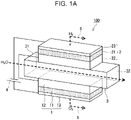
Fig. 1A] Fig. 1A is a perspective view of an electrochemical cell according to a first embodiment of the present disclosure. - [
Fig. 1B] Fig. 1B is a cross-sectional view of the electrochemical cell according to the first embodiment of the present disclosure. - [
Fig. 2] Fig. 2 is a cross-sectional view of an electrochemical cell according to a second embodiment of the present disclosure. - [
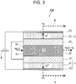
Fig. 3] Fig. 3 is a cross-sectional view of an electrochemical cell according to a third embodiment of the present disclosure. - [
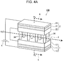
Fig. 4A] Fig. 4A is a perspective view of an electrochemical cell according to a fourth embodiment of the present disclosure. - [
Fig. 4B] Fig. 4B is a cross-sectional view of the electrochemical cell according to the fourth embodiment of the present disclosure. - [
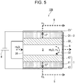
Fig. 5] Fig. 5 is a cross-sectional view of an electrochemical cell according to a fifth embodiment of the present disclosure. - [
Fig. 6] Fig. 6 is a cross-sectional view of an electrochemical cell according to a sixth embodiment of the present disclosure. - [
Fig. 7] Fig. 7 is a cross-sectional view of an electrochemical cell according to a seventh embodiment of the present disclosure. - The present inventors diligently performed studies regarding technologies for separating hydrogen from the gas mixture. As a result, the present inventors discovered that highly concentrated hydrogen can be obtained by using a proton conductor. It was discovered that combining the hydrogen separation that uses a proton conductor with an SOEC enables highly concentrated hydrogen to be generated without relying on a condenser.
- According to a first aspect of the present disclosure, an electrochemical cell includes
- a first cell including a first electrolyte layer containing an oxide ion conductor; and
- a second cell including a second electrolyte layer containing a proton conductor, the second cell being disposed to face the first cell.
- The electrochemical cell of the first aspect facilitates miniaturization of systems that use the electrochemical cell.
- In a second aspect of the present disclosure, the electrochemical cell according to the first aspect may, for example, further include a gas path provided between the first cell and the second cell, and the first cell and the second cell may face each other across the gas path. This configuration enables hydrogen generated in the first cell to be easily directed to the second cell.
- In a third aspect of the present disclosure, the electrochemical cell according to the second aspect may be such that, for example, a downstream end of the gas path is closed. This configuration maximizes water vapor utilization efficiency.
- In a fourth aspect of the present disclosure, the electrochemical cell according to the second or third aspect may, for example, further include a porous layer disposed between the first cell and the second cell, and at least a part of the gas path may be composed of the porous layer. This configuration allows the water vapor and hydrogen necessary for the reactions to circulate through the gas path between the first cell and the second cell while providing a connection between the first cell and the second cell.
- In a fifth aspect of the present disclosure, the electrochemical cell according to the second or third aspect may, for example, further include a support that is disposed in the gas path and the support is in contact with the first cell and the second cell. This configuration allows the water vapor and hydrogen necessary for the reactions to circulate through the gas path between the first cell and the second cell while providing a connection between the first cell and the second cell.
- In a sixth aspect of the present disclosure, the electrochemical cell according to any one of the second to fifth aspects may be such that, for example, a flow path cross-sectional area of an upstream part of the gas path is larger than a flow path cross-sectional area of a downstream part of the gas path. This configuration facilitates one-direction flow of the water vapor used in the reaction, from an upstream side toward a downstream side.
- In a seventh aspect of the present disclosure, the electrochemical cell according to any one of the first to sixth aspects may be such that, for example, the first cell further includes a first electrode and a second electrode; in the first cell, the first electrolyte layer is disposed between the first electrode and the second electrode; the second cell further includes a third electrode and a fourth electrode; in the second cell, the second electrolyte layer is disposed between the third electrode and the fourth electrode; and the first electrode and the third electrode face each other. This configuration enables the water vapor present in the gas path to be rapidly processed in the first electrode and enables the hydrogen present in the gas path to be rapidly processed in the third electrode.
- In an eighth aspect of the present disclosure, the electrochemical cell according to the seventh aspect may be such that, for example, , hydrogen is generated at the first electrode, hydrogen is generated at the second electrode, hydrogen is converted to protons at the third electrode, and hydrogen is generated at the fourth electrode. This configuration enables the production of highly concentrated hydrogen.
- In a ninth aspect of the present disclosure, the electrochemical cell according to any one of the first to eighth aspects may, for example, further include a power source that supplies power to the first cell and the second cell. This configuration enables reliable supply of necessary electrical energy to the first cell and the second cell, thereby enabling efficient generation of highly concentrated hydrogen.
- In a tenth aspect of the present disclosure, the electrochemical cell according to any one of the first to eighth aspects may, for example, further include a first power source that supplies power to the first cell; and a second power source that supplies power to the second cell. This configuration enables separate supply of power to the first cell and the second cell, with each of the supplies being in a suitable amount for high-output operation.
- In an eleventh aspect of the present disclosure, the electrochemical cell according to any one of the first to tenth aspects may be such that, for example, the proton conductor includes at least one selected from the group consisting of BaZr1-x1M1x1O3-δ, BaCe1-x2M2x2O3-δ, and BaZr1-x3-y3Cex3M3y3O3-δ. M1, M2, and M3 may each include at least one selected from the group consisting of Pr, Nd, Pm, Sm, Eu, Gd, Tb, Dy, Ho, Er, Tm, Yb, Y, Sc, In, and Lu; a value of x1 satisfies 0 < x1 < 1; a value of x2 satisfies 0 < x2 < 1; a value of x3 satisfies 0 < x3 < 1; a value of y3 satisfies 0 < y3 < 1; and a value of δ satisfies 0 < δ < 0.5. These proton conductors have high proton conductivity at an operating temperature of the electrochemical cell.
- In a twelfth aspect of the present disclosure, the electrochemical cell according to the eleventh aspect may be such that, for example, the proton conductor is made of BaZr1-x1M1x1O3-δ. BaZr1-x1Ybx1O3-δ has high proton conductivity.
- In a thirteenth aspect of the present disclosure, the electrochemical cell according to the seventh aspect may be such that, for example hydrogen is converted to protons at the fourth electrode, hydrogen is generated at the third electrode, and the first cell generates power by using hydrogen supplied to the first electrode and oxygen supplied to the second electrode. This configuration enables the supply of electrical energy to the outside.
- According to a fourteenth aspect of the present disclosure, a hydrogen generation method includes
- disposing a first cell and a second cell so as to face each other, the first cell including an oxide ion conductor as an electrolyte, the second cell including a proton conductor as an electrolyte;
- generating hydrogen and oxygen by decomposing water vapor by using the first cell; and
- separating the hydrogen from a mixture gas of the hydrogen generated in the first cell and water vapor which has not been decomposed in the first cell.
- The fourteenth aspect enables efficient generation of highly concentrated hydrogen.
- Embodiments of the present disclosure will now be described with reference to the drawings. The present disclosure is not limited to the embodiments described below.
-
Fig. 1A illustrates, in perspective view, a configuration of anelectrochemical cell 100, according to a first embodiment of the present disclosure.Fig. 1B illustrates a cross section of theelectrochemical cell 100 illustrated inFig. 1A . Theelectrochemical cell 100 includes afirst cell 1 and asecond cell 2. Thesecond cell 2 is disposed to face thefirst cell 1. - The
first cell 1 is formed of afirst electrolyte layer 11, afirst electrode 12, and asecond electrode 13. Thefirst electrolyte layer 11 is disposed between thefirst electrode 12 and thesecond electrode 13. Thefirst electrolyte layer 11 includes an oxide ion conductor that serves as an electrolyte. - The
second cell 2 is formed of asecond electrolyte layer 21, athird electrode 22, and afourth electrode 23. Thesecond electrolyte layer 21 is disposed between thethird electrode 22 and thefourth electrode 23. Thesecond electrolyte layer 21 includes a proton conductor that serves as an electrolyte. - In the present embodiment, the
first cell 1 and thesecond cell 2 both have a plate shape and are arranged to be parallel to each other with a predetermined space therebetween. - In the
electrochemical cell 100, thefirst cell 1 plays a role different from the role of thesecond cell 2. Thefirst cell 1 generates hydrogen and oxygen by decomposing water vapor. This process is high-temperature water vapor electrolysis that uses an SOEC. Thesecond cell 2 selectively separates the hydrogen from a gas mixture of the hydrogen generated in thefirst cell 1 and the water vapor which has not been decomposed in thefirst cell 1, by using the function of the proton conductor. Accordingly, highly concentrated hydrogen can be produced. Since thefirst cell 1 and thesecond cell 2 face each other, the hydrogen generated in thefirst cell 1 easily reaches thesecond cell 2 and is immediately processed by thesecond cell 2. - The
electrochemical cell 100 of the present embodiment enables the generation of highly concentrated hydrogen without requiring the use of a condenser for removing water vapor from the gas mixture. That is, theelectrochemical cell 100 facilitates miniaturization of a hydrogen generation system. Of course, theelectrochemical cell 100 can be used in combination with a condenser. In this case, miniaturization of the system can be expected to be achieved by reducing a size of the condenser. - In this specification, the terms "hydrogen" and "oxygen" refer to "hydrogen gas" and "oxygen gas", respectively, unless otherwise specified.
- Regarding the
first cell 1, examples of the oxide ion conductor that is used in thefirst electrolyte layer 11 include stabilized zirconia, lanthanum gallate-based oxides, and ceria-based oxides. Typically, thefirst electrolyte layer 11 is formed of yttria-stabilized zirconia (YSZ). - The
first electrode 12 includes a catalyst for promoting an electrochemical oxidation reaction of the water vapor. The catalyst may be a metal, such as Ni. Thefirst electrode 12 may be made of a cermet. The cermet is a mixture of a metal and a ceramic material. Examples of the cermet include Ni-YSZ and a mixture of Ni and a ceria-based oxide. In instances where thefirst electrode 12 is formed of a cermet, an expected effect is an increase in the reactive active sites for oxidizing water vapor. Thefirst electrode 12 may be a porous body so as to facilitate the diffusion of water vapor. - The
second electrode 13 includes a catalyst for promoting an electrochemical oxidation reaction of oxide ions. The catalyst may be an oxide containing at least one selected from the group consisting of Mn, Fe, Co, and Ni. Specific examples of the catalyst include lanthanum strontium cobalt iron complex oxide (LSCF), lanthanum strontium cobalt complex oxide (LSC), lanthanum strontium iron complex oxide (LSF), lanthanum strontium manganese complex oxide (LSM), barium strontium cobalt iron complex oxide (BSCF), samarium strontium cobalt complex oxide (SSC), lanthanum nickel iron complex oxide, lanthanum nickel complex oxide, and barium gadolinium lanthanum cobalt complex oxide. The catalyst may be a composite of a first oxide and a second oxide or a composite of the first oxide and a metal. The first oxide contains at least one selected from the group consisting of Mn, Fe, Co, and Ni. Thesecond electrode 13 may be a porous body so as to facilitate the diffusion of the generated oxygen. - Regarding the
second cell 2, examples of the proton conductor that is used in thesecond electrolyte layer 21 include proton-conducting oxides. Specifically, the proton conductor that is included in thesecond electrolyte layer 21 may be at least one selected from the group consisting of BaZr1-x1M1xlO3-δ, BaCe1-x2M2x2O3-δ and BaZr1-x3-y3Cex3M3y3O3-δ. M1, M2, and M3 may each include at least one selected from the group consisting of Pr, Nd, Pm, Sm, Eu, Gd, Tb, Dy, Ho, Er, Tm, Yb, Y, Sc, In, and Lu. x1 satisfies 0 < x1 < 1. x2 satisfies 0 < x2 < 1. x3 satisfies 0 < x3 < 1. y3 satisfies 0 < y3 < 1. The value of δ satisfies 0 < δ < 0.5. These proton conductors have high proton conductivity. Using a solid electrolyte having high proton conductivity improves the electrochemical performance of thesecond cell 2. The proton conductor may be made of BaZr1-x1Ybx1O3-δ. BaZr1-x1Ybx1O3-δ has high proton conductivity. The variable δ is a value by which an amount of oxygen deficiency in the crystal lattice of the oxide is indicated on the composition. The value of δ varies depending on the value of x1, the value of x2, the value of x3, the value of y3, a temperature, an oxygen partial pressure, a water vapor partial pressure, and the like. Thesecond electrolyte layer 21 may be a dense body. - The
third electrode 22 includes a catalyst for electrochemically oxidizing hydrogen. The catalyst may be a metal, such as Ni. Thethird electrode 22 may be formed of a cermet. The cermet may be a mixture of Ni and a proton-conducting oxide, and examples of the mixture include a mixture of Ni and BaZr1-x1Ybx1O3-δ. In instances where thethird electrode 22 is formed of a cermet, an expected effect is an increase in the reactive active sites for oxidizing hydrogen. Thethird electrode 22 may be a porous body so as to facilitate the diffusion of hydrogen and water vapor. - The
fourth electrode 23 includes a catalyst for electrochemically reducing protons. The catalyst may be a metal, such as Ni. Thefourth electrode 23 may be formed of a cermet. The cermet may be a mixture of Ni and a proton-conducting oxide, and examples of the mixture include a mixture of Ni and BaZr1-x1Ybx1O3-δ. In instances where thefourth electrode 23 is formed of a cermet, an expected effect is an increase in the reactive active sites for reducing protons. Thefourth electrode 23 may be a porous body so as to facilitate the diffusion of hydrogen. - The "porous body" or a "porous" refers to a material having a porosity of greater than or equal to 20%, for example. The porosity can be measured by using an Archimedes method or a mercury intrusion porosimetry method.
- The
electrochemical cell 100 further includes agas path 3. Thegas path 3 is provided between thefirst cell 1 and thesecond cell 2. Thefirst cell 1 and thesecond cell 2 face each other across thegas path 3. This configuration enables the hydrogen generated in thefirst cell 1 to be easily directed to thesecond cell 2. The water vapor electrolysis in thefirst cell 1 and the hydrogen separation in thesecond cell 2 proceed smoothly. - The
first cell 1 and thesecond cell 2 face thegas path 3. Specifically, thefirst electrode 12 of thefirst cell 1 and thethird electrode 22 of thesecond cell 2 face thegas path 3. Thefirst electrode 12 and thethird electrode 22 face each other. In other words, at least a part of an inner wall surface of thegas path 3 is composed of thefirst electrode 12 and thethird electrode 22. This configuration enables the water vapor present in thegas path 3 to be rapidly processed in thefirst electrode 12 and enables the hydrogen present in thegas path 3 to be rapidly processed in thethird electrode 22. - The
gas path 3 may be a space between thefirst cell 1 and thesecond cell 2. For example, in an instance where thefirst cell 1 and thesecond cell 2 have a cylindrical shape and are disposed concentrically, the space between thefirst cell 1 and thesecond cell 2 composes thegas path 3. Alternatively, a different member, other than thefirst cell 1 or thesecond cell 2, may constitute thegas path 3. The different member may be a metal conduit. Thefirst cell 1 and thesecond cell 2 may be mounted to the metal conduit such that thefirst cell 1 and thesecond cell 2 face an inner part of the metal conduit. - The
gas path 3 includes aninlet 31 and anoutlet 32. Water vapor, which is the raw material for the water vapor electrolysis, is fed to theelectrochemical cell 100 through theinlet 31. Unreacted hydrogen and unreacted water vapor are discharged from theelectrochemical cell 100 through theoutlet 32. - Note that the
electrochemical cell 100 may include a connection structure so that thegas path 3 can be ensured, that is, a configuration in which thefirst cell 1 is separated from thesecond cell 2 can be provided. For example, the connection structure is provided at each of four corners of thefirst cell 1 and thesecond cell 2. The connection structure holds thefirst cell 1 and thesecond cell 2 in a manner such that thefirst electrode 12 of thefirst cell 1 is separated from thethird electrode 22 of thesecond cell 2. - The
electrochemical cell 100 further includes anoxygen passage 5 and ahydrogen passage 6. Theoxygen passage 5 is a passage through which oxygen generated in thefirst cell 1 flows. Theoxygen passage 5 is connected to thefirst cell 1. Specifically, theoxygen passage 5 is connected to thesecond electrode 13 of thefirst cell 1. A terminal end of theoxygen passage 5 is connected to, for example, oxygen storage equipment. Thehydrogen passage 6 is a passage through which hydrogen separated in thesecond cell 2 flows. Thehydrogen passage 6 is connected to thesecond cell 2. Specifically, thehydrogen passage 6 is connected to thefourth electrode 23 of thesecond cell 2. A terminal end of thehydrogen passage 6 is connected to, for example, hydrogen storage equipment. Theoxygen passage 5 and thehydrogen passage 6 may be composed of a heatresistant conduit, which may be, for example, a metal conduit. - The
electrochemical cell 100 further includes apower source 4. Thepower source 4 supplies power to thefirst cell 1 and thesecond cell 2. In the present embodiment, thepower source 4 is shared by thefirst cell 1 and thesecond cell 2. Thepower source 4 is connected to thesecond electrode 13 of thefirst cell 1 and to thefourth electrode 23 of thesecond cell 2. Thefirst electrode 12 of thefirst cell 1 is electrically connected to thethird electrode 22 of thesecond cell 2. That is, thefirst cell 1 is connected to thesecond cell 2 in series. Thepower source 4 enables reliable supply of necessary electrical energy to thefirst cell 1 and thesecond cell 2, thereby enabling efficient generation of highly concentrated hydrogen. The shared use of thepower source 4 by thefirst cell 1 and thesecond cell 2 contributes to a cost reduction. - Now, operation of the
electrochemical cell 100 will be described in detail. In theelectrochemical cell 100, a step of generating hydrogen and oxygen by electrolyzing water vapor and a step of separating hydrogen from a gas mixture of hydrogen and water vapor proceed in parallel. The step of generating hydrogen and oxygen is carried out by using thefirst cell 1, which includes an oxide ion conductor that serves as an electrolyte. The step of separating hydrogen from a gas mixture is carried out by using thesecond cell 2, which includes a proton conductor that serves as an electrolyte. The gas mixture contains the hydrogen generated in thefirst cell 1 and the water vapor which has not been decomposed in thefirst cell 1. Implementation of these steps enables efficient generation of highly concentrated hydrogen. - First, the
power source 4 is turned on to supply water vapor to thegas path 3. When the water vapor reaches a surface of thefirst cell 1, the water vapor is reduced to hydrogen and oxide ions at thefirst electrode 12. Specifically, the water vapor is reduced to hydrogen and oxide ions at or near an interface between thefirst electrolyte layer 11 and thefirst electrode 12. The oxide ions migrate through thefirst electrolyte layer 11 to reach thesecond electrode 13. At thesecond electrode 13, an oxidation reaction of the oxide ions occurs, which generates oxygen. Specifically, the oxide ions are oxidized and converted to oxygen at or near an interface between thefirst electrolyte layer 11 and thesecond electrode 13. The oxygen is discharged from thesecond electrode 13 and directed to the outside of theelectrochemical cell 100 through theoxygen passage 5. - The hydrogen generated at the surface of the
first cell 1 diffuses through thegas path 3 to reach a surface of thesecond cell 2. When the hydrogen reaches the surface of thesecond cell 2, the hydrogen is oxidized and converted to protons at thethird electrode 22. Specifically, the hydrogen is oxidized and converted to protons at or near an interface between thesecond electrolyte layer 21 and thethird electrode 22. The protons migrate through thesecond electrolyte layer 21 to reach thefourth electrode 23. At thefourth electrode 23, a reduction reaction of the protons occurs, which generates hydrogen. Specifically, the protons are reduced and converted to hydrogen at or near an interface between thesecond electrolyte layer 21 and thefourth electrode 23. The hydrogen is directed to the outside of theelectrochemical cell 100 through thehydrogen passage 6. Based on the reactions described above, only the hydrogen generated by the reaction at or near the interface between thesecond electrolyte layer 21 and thefourth electrode 23 is supplied to the outside of theelectrochemical cell 100. Accordingly, highly concentrated hydrogen can be obtained. - A gas mixture of unreacted hydrogen and unreacted water vapor is discharged to the outside of the
electrochemical cell 100 through thegas path 3. - The reaction at each of the electrodes is as follows.
- First electrode 12:
2H2O + 4e- → 2H2 + 2O2-
- Second electrode 13:
202- → O2 + 4e-
- Third electrode 22:
H2 → 2H+ + 2e-
- Fourth electrode 23:
2H+ + 2e- → H2
- During the operation of the
electrochemical cell 100, an ambient temperature (i.e., an operating temperature) of thefirst cell 1 and thesecond cell 2 is maintained at greater than or equal to 500°C and less than or equal to 1000°C, for example. The operating temperature is specified based on an oxide ion conductivity of the oxide ion conductor included in thefirst electrolyte layer 11. For example, in an instance where yttria-stabilized zirconia is used in thefirst electrolyte layer 11, the operating temperature may be set to be greater than or equal to 700°C. The temperature at which thesecond electrolyte layer 21 exhibits sufficient proton conductivity is approximately 600°C, which is less than the temperature suitable for thefirst electrolyte layer 11. Thefirst cell 1 and thesecond cell 2 may be stored in a thermally insulating housing. - Some additional embodiments will be described below. Elements of an embodiment that are common with those of the first embodiment are designated with the same reference numerals, and descriptions thereof may be omitted. Regarding the embodiments disclosed herein, the description of one embodiment may apply to another embodiment as long as there is no technical inconsistency. Any combination of the embodiments is possible as long as there is no technical inconsistency.
-
Fig. 2 illustrates a cross section of anelectrochemical cell 102, according to a second embodiment of the present disclosure. Theelectrochemical cell 102 includes afirst power source 41 and asecond power source 42, instead of thepower source 4. Thefirst power source 41 supplies power to afirst cell 1. Thefirst power source 41 is connected to afirst electrode 12 of thefirst cell 1 and to asecond electrode 13 of thefirst cell 1. Thesecond power source 42 supplies power to asecond cell 2. Thesecond power source 42 is connected to athird electrode 22 of thesecond cell 2 and to afourth electrode 23 of thesecond cell 2. - In the instance of the
power source 4, which has been described earlier, since thefirst cell 1 and thesecond cell 2 are connected to each other in series, currents with the same value flow through thefirst cell 1 and thesecond cell 2. However, the current value suitable for the water vapor electrolysis reaction in thefirst cell 1 may be different from the current value suitable for the electrochemical hydrogen separation in thesecond cell 2. The present embodiment enables separate control of thefirst power source 41 and thesecond power source 42. In this instance, an amount of power suitable for thefirst cell 1 and an amount of power suitable for thesecond cell 2 can be supplied, and, therefore, theelectrochemical cell 102 has excellent control. - In the present embodiment, the
first cell 1 and thesecond cell 2 are electrically insulated from each other. Theelectrochemical cell 102 may further include aninsulator layer 7 so that thefirst cell 1 and thesecond cell 2 can be reliably isolated from each other. Theinsulator layer 7 may be disposed between thefirst cell 1 and thesecond cell 2. Theinsulator layer 7 can be disposed in thegas path 3 such that, for example, theinsulator layer 7 divides thegas path 3 along a gas flow direction. Example of a material of theinsulator layer 7 include oxides, such as alumina, stabilized zirconia, and barium zirconate-based oxides. Another material that can be used as a material of theinsulator layer 7 is a glassbased seal material. -
Fig. 3 illustrates a cross section of anelectrochemical cell 104, according to a third embodiment of the present disclosure. Theelectrochemical cell 104 additionally includes aporous layer 33, which is disposed between afirst cell 1 and asecond cell 2. At least a part of agas path 3 is composed of theporous layer 33. Theporous layer 33 connects thefirst cell 1 to thesecond cell 2. Thefirst cell 1 and thesecond cell 2 are secured to each other by theporous layer 33. - The
porous layer 33 allows the water vapor and hydrogen necessary for the reactions to circulate through thegas path 3 between thefirst cell 1 and thesecond cell 2 while providing a connection between thefirst cell 1 and thesecond cell 2. Theelectrochemical cell 104 can be provided which, as a whole, efficiently contributes to the reactions while allowing the circulation of the water vapor supplied from the outside and the hydrogen generated at thefirst electrode 12. - Examples of a porous material that forms the
porous layer 33 include porous ceramics, porous metal bodies, and metal meshes. For example, theporous layer 33 has a porosity of greater than or equal to 20%. Note that in an instance where theporous layer 33 is made of a metal, insulation may be provided to prevent shorting between thefirst electrode 12 and thethird electrode 22 from occurring via theporous layer 33. -
Fig. 4A illustrates, in perspective view, a configuration of anelectrochemical cell 106, according to a fourth embodiment of the present disclosure.Fig. 4B illustrates a cross section of theelectrochemical cell 106 illustrated inFig. 4A . Theelectrochemical cell 106 additionally includes at least onesupport 34, which is disposed in thegas path 3. In the present embodiment, a plurality ofsupports 34 are provided. The supports 34 connect afirst cell 1 to asecond cell 2. The supports 34 secure thefirst cell 1 and thesecond cell 2 to each other. - The supports 34 allow the water vapor and hydrogen necessary for the reactions to circulate through the
gas path 3 between thefirst cell 1 and thesecond cell 2 while providing a connection between thefirst cell 1 and thesecond cell 2. Theelectrochemical cell 106 can be provided which, as a whole, efficiently contributes to the reactions while allowing the circulation of the water vapor supplied from the outside and the hydrogen generated at thefirst electrode 12. - In the present embodiment, the
supports 34 are regularly arranged. The supports 34 are spaced at equal intervals in a water vapor flow direction. However, the arrangement of thesupports 34 is not particularly limited provided that thefirst cell 1 and thesecond cell 2 are stably secured to each other. The factors that determine the arrangement of thesupports 34 include the number of thesupports 34 and positions of thesupports 34. For example, when both thefirst cell 1 and thesecond cell 2 have a rectangular parallelepiped shape, thesupport 34 may be provided at each of the four corners. - Examples of a material of the
supports 34 include metals, ceramics, and cermets. Specific examples include Ni and Ni-containing cermets. Examples of the Ni-containing cermets include Ni-YSZ and Ni-BaZr1-x1Ybx1O3-δ. Note that in an instance where thesupports 34 are made of a metal, insulation may be provided to prevent shorting between thefirst electrode 12 and thethird electrode 22 from occurring via thesupports 34. -
Fig. 5 illustrates a cross section of anelectrochemical cell 108, according to a fifth embodiment of the present disclosure. In theelectrochemical cell 108, a downstream end of agas path 3 is closed. In other words, anoutlet 32 of thegas path 3 is closed. In the instance where thegas path 3 is closed, the entirety of the supplied water vapor is used for the water vapor electrolysis reaction. That is, water vapor utilization efficiency can be maximized. - The
electrochemical cell 108 additionally includes aseal member 8, which is a member for closing thegas path 3. Theseal member 8 is provided on a downstream side of thegas path 3 with respect to a water vapor flow direction. Theseal member 8 also serves to connect afirst cell 1 to asecond cell 2. In the present embodiment, theseal member 8 is attached to end surfaces of thefirst cell 1 and thesecond cell 2, which are downstream side surfaces with respect to the water vapor flow direction. Accordingly, outflow of the water vapor to the outside of the space (e.g., the gas path 3) between thefirst cell 1 and thesecond cell 2 is prevented. - Examples of a material of the
seal member 8 include seal materials, such as thermiculite and crystalline glass. - In the present embodiment, the
seal member 8 has a plate shape and extends from a side surface of thefirst electrolyte layer 11 to a side surface of thesecond electrolyte layer 21 to connect thefirst cell 1 and thesecond cell 2 to each other. It should be noted that the structure for closing the downstream end of thegas path 3 is not particularly limited. For example, theseal member 8 may be present exclusively on a region from a side surface of thefirst electrode 12 to a side surface of thethird electrode 22. Thefirst electrode 12 may be connected to thethird electrode 22 by theseal member 8. - Furthermore, the
seal member 8 may be configured such that the downstream end of thegas path 3, that is, theoutlet 32 of thegas path 3 can be opened and closed. For example, theseal member 8 may be provided with a gas discharge mechanism such as an on-off solenoid valve. In the instance where theoutlet 32 of thegas path 3 is closed, impurities that do not contribute to the water vapor electrolysis reaction may accumulate in thegas path 3. By controlling the gas discharge mechanism to open theoutlet 32 of thegas path 3, thereby removing impurities regularly or at a selected timing, it is possible to continue an efficient water vapor electrolysis reaction and continue efficient hydrogen separation. -
Fig. 6 illustrates a cross section of anelectrochemical cell 110, according to a sixth embodiment of the present disclosure. In theelectrochemical cell 110, a flow path cross-sectional area of agas path 3 is larger at an upstream part of thegas path 3 than at a downstream part of thegas path 3. In other words, an open area of aninlet 31 of thegas path 3 is larger than an open area of anoutlet 32 of thegas path 3. The flow path cross-sectional area of thegas path 3 continuously decreases in a water vapor flow direction. In other words, a distance between thefirst electrode 12 and thethird electrode 22 continuously decreases in the water vapor flow direction. This configuration facilitates one-direction flow of the water vapor used in the reaction, from an upstream side toward a downstream side. This enables the water vapor electrolysis reaction to proceed efficiently. - In the present embodiment, the above-described configuration is realized by configuring a thickness of at least one of the
first electrode 12 or thethird electrode 22 such that the thickness continuously increases from the upstream side of thegas path 3 toward the downstream side thereof. Note that even in instances where the flow path cross-sectional area of thegas path 3 decreases in a stepwise manner, the same effect can be produced, depending on a shape of thegas path 3. - The "open area of the
inlet 31 of thegas path 3" refers to the flow path cross-sectional area of thegas path 3 at a position of an upstream end of afirst cell 1 and asecond cell 2. The "open area of theoutlet 32 of thegas path 3" refers to the flow path cross-sectional area of thegas path 3 at a position of a downstream end of thefirst cell 1 and thesecond cell 2. The "position of an upstream end" refers to a position of the upstream end with respect to the water vapor flow direction. The "position of a downstream end" refers to a position of the downstream end with respect to the water vapor flow direction. Note that, inFig. 6 , the thickness of thefirst electrode 12 is varied, and the thickness of thethird electrode 22 is varied. However, the thicknesses may not necessarily be varied. In other words, the thickness of thefirst electrode 12 may be uniform, and the thickness of thethird electrode 22 may be uniform. For example, thefirst cell 1 and thesecond cell 2 may be positioned not parallel to each other but oblique to each other. In instances where such a configuration is employed, the open area of theinlet 31 of thegas path 3 is larger than the open area of theoutlet 32 of thegas path 3 in theelectrochemical cell 110. -
Fig. 7 illustrates a cross section of anelectrochemical cell 100a, according to a seventh embodiment of the present disclosure. Theelectrochemical cell 100a has the same configuration as the configuration of theelectrochemical cell 100, which has been described with reference toFig. 1 , except that anexternal load 4a replaces thepower source 4. The configurations of afirst cell 1 and asecond cell 2 are as described above in the first embodiment. - The reaction that proceeds at each of the electrodes of the
electrochemical cell 100a is a reaction in the reverse direction to that of the reaction that proceeds at each of the electrodes of theelectrochemical cell 100 of the first embodiment. In the present embodiment, a power generation reaction is carried out in thefirst cell 1 by using oxygen supplied from the outside and hydrogen that has passed through thesecond cell 2. The present embodiment enables the supply of electrical energy to the outside. The present embodiment is different from the first embodiment in this regard. - Operation of the
electrochemical cell 100a will be described in detail. - An operating temperature of the
first cell 1 and thesecond cell 2 is, for example, greater than or equal to 500°C and less than or equal to 1000°C. Thus, the same operating temperature may be used in the present embodiment and the first embodiment. - First, hydrogen is supplied to a
fourth electrode 23 of thesecond cell 2. At thefourth electrode 23, an oxidation reaction of the hydrogen occurs, which generates protons. Specifically, the hydrogen is oxidized and converted to protons at or near an interface between asecond electrolyte layer 21 and thefourth electrode 23. The protons migrate through thesecond electrolyte layer 21 to reach athird electrode 22. At thethird electrode 22, a reduction reaction of the protons occurs, which generates hydrogen. Specifically, the protons are reduced and converted to hydrogen at or near an interface between thesecond electrolyte layer 21 and thethird electrode 22. The hydrogen generated at a surface of thesecond cell 2 diffuses through thegas path 3 to reach a surface of thefirst cell 1. - The
first cell 1 generates power by using the hydrogen supplied to thefirst electrode 12 and the oxygen supplied to asecond electrode 13. Specifically, a gas containing oxygen is supplied to thesecond electrode 13 of thefirst cell 1. A typical example of the gas containing oxygen is air. At thesecond electrode 13, a reduction reaction of the oxygen occurs, which generates oxide ions. The oxide ions migrate through thefirst electrolyte layer 11 to reach thefirst electrode 12. At thefirst electrode 12, an electrochemical reaction that generates water vapor and electrons from the oxide ions and hydrogen proceeds. The water vapor and unreacted hydrogen are directed to the outside of theelectrochemical cell 100a through thegas path 3. The hydrogen may be combusted by using a burner or by catalytic combustion. - The reaction at each of the electrodes is as follows.
- First electrode 12:
2H2 + 202- → 2H2O + 4e-
- Second electrode 13:
O2 + 4e- → 2O2 "
- Third electrode 22:
2H+ + 2e- → H2
- Fourth electrode 23:
H2 → 2H+ + 2e-
- The present embodiment enables pure hydrogen to be generated in the
second cell 2 and supplied to thefirst cell 1 even in instances in which the gas to be supplied to thefourth electrode 23 of thesecond cell 2 contains not only hydrogen but also impurities, such as water vapor or carbon dioxide. As a result, the following effects, for instance, are produced in the first cell 1: improvement in power generation performance and inhibition of carbon deposition. The gas to be supplied to thesecond cell 2 may be, for example, a hydrogen-containing gas obtained by reforming a raw gas, such as methane, or a hydrogen-containing gas obtained by performing water vapor electrolysis. - The reaction that proceeds in the
first cell 1 is an electrochemical reaction that generates water vapor and electrical energy from hydrogen and oxygen (i.e., a reaction in a fuel cell). The electrical energy may be supplied to theexternal load 4a, which is connected to thefirst cell 1. A part of the electrical energy is used as energy for the proton conduction that takes place in thesecond cell 2. Theelectrochemical cell 100a serves as a fuel cell and generates electrical energy. - The present embodiment enables pure hydrogen to be generated in the
second cell 2 and supplied to thefirst cell 1 even in instances in which the gas to be introduced into athird passage 5 contains not only hydrogen but also impurities, such as water vapor or carbon dioxide. As a result, the following effects, for instance, are produced in the first cell 1: improvement in power generation performance and inhibition of carbon deposition. - Electrochemical cells according to the present disclosure are suitable for a hydrogen generation system or a fuel cell system. The electrochemical cells according to the present disclosure may also be utilized in a hydrogen purification apparatus or an electrochemical hydrogen pump, such as a hydrogen compressor. Reference Signs List
-
- 1
- First cell
- 2
- Second cell
- 3
- Gas path
- 4
- Power source
- 5
- Oxygen passage
- 6
- Hydrogen passage
- 7
- Insulator layer
- 8
- Seal member
- 11
- First electrolyte layer
- 12
- First electrode
- 13
- Second electrode
- 21
- Second electrolyte layer
- 22
- Third electrode
- 23
- Fourth electrode
- 31
- Inlet
- 32
- Outlet
- 33
- Porous layer
- 34
- Support
- 41
- First power source
- 42
- Second power source
- 100, 102, 104, 106, 108, 110, 100a
- Electrochemical cell
Claims (14)
- An electrochemical cell comprising:a first cell including a first electrolyte layer containing an oxide ion conductor; anda second cell including a second electrolyte layer containing a proton conductor, the second cell being disposed to face the first cell.
- The electrochemical cell according to Claim 1, further comprising a gas path provided between the first cell and the second cell, wherein
the first cell and the second cell face each other across the gas path. - The electrochemical cell according to Claim 2, wherein a downstream end of the gas path is closed.
- The electrochemical cell according to Claim 2 or 3, further comprising a porous layer disposed between the first cell and the second cell, wherein
at least a part of the gas path is composed of the porous layer. - The electrochemical cell according to Claim 2 or 3, further comprising a support disposed in the gas path and the support is in contact with the first cell and the second cell.
- The electrochemical cell according to any one of Claims 2 to 5, wherein a flow path cross-sectional area of an upstream part of the gas path is larger than a flow path cross-sectional area of a downstream part of the gas path.
- The electrochemical cell according to any one of Claims 1 to 6, whereinthe first cell further includes a first electrode and a second electrode,in the first cell, the first electrolyte layer is disposed between the first electrode and the second electrode,the second cell further includes a third electrode and a fourth electrode,in the second cell, the second electrolyte layer is disposed between the third electrode and the fourth electrode, andthe first electrode and the third electrode face each other.
- The electrochemical cell according to Claim 7, whereinhydrogen is generated at the first electrode,hydrogen is generated at the second electrode,hydrogen is converted to protons at the third electrode, andhydrogen is generated at the fourth electrode.
- The electrochemical cell according to any one of Claims 1 to 8, further comprising a power source that supplies power to the first cell and the second cell.
- The electrochemical cell according to any one of Claims 1 to 8, further comprising:a first power source that supplies power to the first cell; anda second power source that supplies power to the second cell.
- The electrochemical cell according to any one of Claims 1 to 10, wherein the proton conductor includes at least one selected from the group consisting of BaZr1-x1M1x1O3-δ, BaCe1-x2M2x2O3-δ, and BaZr1-x3-y3Cex3M3y3O3-δ, whereM1, M2, and M3 each include at least one selected from the group consisting of Pr, Nd, Pm, Sm, Eu, Gd, Tb, Dy, Ho, Er, Tm, Yb, Y, Sc, In, and Lu,a value of x1 satisfies 0 < x1 < 1,a value of x2 satisfies 0 < x2 < 1,a value of x3 satisfies 0 < x3 < 1,a value of y3 satisfies 0 < y3 < 1, anda value of δ satisfies 0 < δ < 0.5.
- The electrochemical cell according to Claim 11, wherein the proton conductor is made of BaZr1-x1M1x1O3-δ.
- The electrochemical cell according to Claim 7, whereinhydrogen is converted to protons at the fourth electrode,hydrogen is generated at the third electrode, andthe first cell generates power by using hydrogen supplied to the first electrode and oxygen supplied to the second electrode.
- A hydrogen generation method comprising:disposing a first cell and a second cell so as to face each other, the first cell including an oxide ion conductor as an electrolyte, the second cell including a proton conductor as an electrolyte;generating hydrogen and oxygen by decomposing water vapor by using the first cell; andseparating the hydrogen from a mixture gas of the hydrogen generated in the first cell and water vapor which has not been decomposed in the first cell.
Applications Claiming Priority (2)
| Application Number | Priority Date | Filing Date | Title |
|---|---|---|---|
| JP2019098695 | 2019-05-27 | ||
| PCT/JP2020/018754 WO2020241211A1 (en) | 2019-05-27 | 2020-05-11 | Electrochemical cell and hydrogen generation method |
Publications (3)
| Publication Number | Publication Date |
|---|---|
| EP3978652A1 true EP3978652A1 (en) | 2022-04-06 |
| EP3978652A4 EP3978652A4 (en) | 2022-09-21 |
| EP3978652B1 EP3978652B1 (en) | 2025-01-22 |
Family
ID=73554003
Family Applications (1)
| Application Number | Title | Priority Date | Filing Date |
|---|---|---|---|
| EP20814181.2A Active EP3978652B1 (en) | 2019-05-27 | 2020-05-11 | Electrochemical cell and hydrogen generation method |
Country Status (5)
| Country | Link |
|---|---|
| US (1) | US20220045348A1 (en) |
| EP (1) | EP3978652B1 (en) |
| JP (1) | JP7555037B2 (en) |
| CN (1) | CN113366153A (en) |
| WO (1) | WO2020241211A1 (en) |
Family Cites Families (15)
| Publication number | Priority date | Publication date | Assignee | Title |
|---|---|---|---|---|
| JPH0668974B2 (en) * | 1987-10-12 | 1994-08-31 | 日本電信電話株式会社 | Fuel cell |
| US7022429B2 (en) * | 2002-04-25 | 2006-04-04 | General Electric Company | Fluid passages for power generation equipment |
| FR2883420B1 (en) | 2005-03-17 | 2007-05-11 | Armines Ass Loi De 1901 | HIGH TEMPERATURE FUEL CELL WITH ANIONIC AND PROTONIC MIXED CONDUCTION CELL |
| JP5481611B2 (en) * | 2008-04-28 | 2014-04-23 | 国立大学法人山梨大学 | High temperature steam electrolysis cell |
| US20110151349A1 (en) * | 2008-06-10 | 2011-06-23 | Technion Research & Development Foundation Ltd. | Double-electrolyte fuel-cell |
| JP2010176939A (en) | 2009-01-28 | 2010-08-12 | Toshiba Corp | Power storage system, and operation method thereof |
| FR2969179B1 (en) * | 2010-12-20 | 2013-02-08 | Commissariat Energie Atomique | HYDROGEN PRODUCTION CELL COMPRISING A HIGH TEMPERATURE WATER VAPOR ELECTROLYSER CELL |
| FR2976591B1 (en) * | 2011-06-16 | 2013-07-12 | Commissariat Energie Atomique | SIMPLIFIED REALIZATION INTERCONNECTOR MODULE FOR HIGH-TEMPERATURE WATER ELECTROLYSIS DEVICE |
| JP2013054868A (en) * | 2011-09-01 | 2013-03-21 | Konica Minolta Holdings Inc | Secondary battery type fuel cell |
| EP2675007A1 (en) * | 2012-06-11 | 2013-12-18 | HTceramix S.A. | A gas flow dividing element |
| FR3038916B1 (en) * | 2015-07-16 | 2017-07-28 | Commissariat Energie Atomique | METHODS OF (CO) ELECTROLYSIS OF WATER (SOEC) OR PRODUCTION OF HIGH TEMPERATURE ELECTRICITY WITH INTEGRATED EXCHANGERS AS REACTOR STACK (EHT) OR FUEL CELL (SOFC) ) |
| FR3045950B1 (en) * | 2015-12-17 | 2020-02-28 | Electricite De France | PROTONIC CONDUCTION ELECTROCHEMICAL DEVICE WITH INTEGRATED REFORMING AND MANUFACTURING METHOD THEREOF |
| JPWO2018029994A1 (en) * | 2016-08-09 | 2019-02-14 | 本田技研工業株式会社 | Hydrogen treatment equipment |
| JP6696696B2 (en) * | 2017-03-21 | 2020-05-20 | 株式会社東芝 | Electrochemical reactor |
| JP2019056136A (en) * | 2017-09-20 | 2019-04-11 | 株式会社東芝 | Electrochemical reactor |
-
2020
- 2020-05-11 EP EP20814181.2A patent/EP3978652B1/en active Active
- 2020-05-11 JP JP2021522167A patent/JP7555037B2/en active Active
- 2020-05-11 CN CN202080011301.8A patent/CN113366153A/en active Pending
- 2020-05-11 WO PCT/JP2020/018754 patent/WO2020241211A1/en not_active Ceased
-
2021
- 2021-10-20 US US17/505,695 patent/US20220045348A1/en not_active Abandoned
Also Published As
| Publication number | Publication date |
|---|---|
| EP3978652B1 (en) | 2025-01-22 |
| EP3978652A4 (en) | 2022-09-21 |
| JP7555037B2 (en) | 2024-09-24 |
| CN113366153A (en) | 2021-09-07 |
| JPWO2020241211A1 (en) | 2020-12-03 |
| WO2020241211A1 (en) | 2020-12-03 |
| US20220045348A1 (en) | 2022-02-10 |
Similar Documents
| Publication | Publication Date | Title |
|---|---|---|
| EP3432401B1 (en) | Phase stable doped zirconia electrolyte compositions with low degradation | |
| US9297086B2 (en) | Hydrogen-producing cell comprising a cell of a high temperature steam electrolyzer | |
| EP3605694A1 (en) | Electrochemical element, electrochemical module, electrochemical device, energy system, solid oxide fuel cell, and method for producing electrochemical element | |
| EP2908371B1 (en) | Fuel battery and operation method thereof | |
| WO2005078160A1 (en) | Process for producing hydrogen and apparatus therefor | |
| EP3978651A1 (en) | Electrochemical device and hydrogen generation method | |
| CA3027772C (en) | Soec system with heating ability | |
| EP3907310A1 (en) | Systems and methods for generating synthesis gas for ammonia production | |
| JP2005513721A (en) | Metal current collector protected by oxide film | |
| US20200087801A1 (en) | Hydrogen processing device | |
| EP3790089A1 (en) | Electrochemical element, electrochemical module, electrochemical device, and energy system | |
| JP4512788B2 (en) | High temperature steam electrolyzer | |
| EP3605695B1 (en) | Electrochemical device, energy system, and solid oxide fuel cell | |
| EP3978652B1 (en) | Electrochemical cell and hydrogen generation method | |
| EP3978650A1 (en) | Electrochemical cell | |
| JP2024131447A (en) | Electrolysis System | |
| JP2024106828A (en) | Fuel cell system and method for controlling the fuel cell system | |
| EP4692424A1 (en) | Steam electrolysis device and steam electrolysis method | |
| JP2025140757A (en) | Electrolysis System |
Legal Events
| Date | Code | Title | Description |
|---|---|---|---|
| STAA | Information on the status of an ep patent application or granted ep patent |
Free format text: STATUS: THE INTERNATIONAL PUBLICATION HAS BEEN MADE |
|
| PUAI | Public reference made under article 153(3) epc to a published international application that has entered the european phase |
Free format text: ORIGINAL CODE: 0009012 |
|
| STAA | Information on the status of an ep patent application or granted ep patent |
Free format text: STATUS: REQUEST FOR EXAMINATION WAS MADE |
|
| 17P | Request for examination filed |
Effective date: 20211028 |
|
| AK | Designated contracting states |
Kind code of ref document: A1 Designated state(s): AL AT BE BG CH CY CZ DE DK EE ES FI FR GB GR HR HU IE IS IT LI LT LU LV MC MK MT NL NO PL PT RO RS SE SI SK SM TR |
|
| REG | Reference to a national code |
Ref country code: DE Ref legal event code: R079 Free format text: PREVIOUS MAIN CLASS: C25B0009100000 Ipc: C25B0009230000 Ref document number: 602020045245 Country of ref document: DE |
|
| DAV | Request for validation of the european patent (deleted) | ||
| DAX | Request for extension of the european patent (deleted) | ||
| A4 | Supplementary search report drawn up and despatched |
Effective date: 20220823 |
|
| RIC1 | Information provided on ipc code assigned before grant |
Ipc: H01M 8/1253 20160101ALI20220817BHEP Ipc: H01M 8/12 20160101ALI20220817BHEP Ipc: C25B 15/08 20060101ALI20220817BHEP Ipc: H01M 4/90 20060101ALI20220817BHEP Ipc: C25B 15/02 20210101ALI20220817BHEP Ipc: C25B 9/77 20210101ALI20220817BHEP Ipc: C25B 9/75 20210101ALI20220817BHEP Ipc: C25B 9/70 20210101ALI20220817BHEP Ipc: C25B 1/042 20210101ALI20220817BHEP Ipc: C25B 9/23 20210101AFI20220817BHEP |
|
| GRAP | Despatch of communication of intention to grant a patent |
Free format text: ORIGINAL CODE: EPIDOSNIGR1 |
|
| STAA | Information on the status of an ep patent application or granted ep patent |
Free format text: STATUS: GRANT OF PATENT IS INTENDED |
|
| INTG | Intention to grant announced |
Effective date: 20240819 |
|
| GRAS | Grant fee paid |
Free format text: ORIGINAL CODE: EPIDOSNIGR3 |
|
| GRAA | (expected) grant |
Free format text: ORIGINAL CODE: 0009210 |
|
| STAA | Information on the status of an ep patent application or granted ep patent |
Free format text: STATUS: THE PATENT HAS BEEN GRANTED |
|
| AK | Designated contracting states |
Kind code of ref document: B1 Designated state(s): AL AT BE BG CH CY CZ DE DK EE ES FI FR GB GR HR HU IE IS IT LI LT LU LV MC MK MT NL NO PL PT RO RS SE SI SK SM TR |
|
| REG | Reference to a national code |
Ref country code: GB Ref legal event code: FG4D |
|
| REG | Reference to a national code |
Ref country code: CH Ref legal event code: EP |
|
| REG | Reference to a national code |
Ref country code: IE Ref legal event code: FG4D |
|
| REG | Reference to a national code |
Ref country code: DE Ref legal event code: R096 Ref document number: 602020045245 Country of ref document: DE |
|
| REG | Reference to a national code |
Ref country code: NL Ref legal event code: MP Effective date: 20250122 |
|
| PG25 | Lapsed in a contracting state [announced via postgrant information from national office to epo] |
Ref country code: NL Free format text: LAPSE BECAUSE OF FAILURE TO SUBMIT A TRANSLATION OF THE DESCRIPTION OR TO PAY THE FEE WITHIN THE PRESCRIBED TIME-LIMIT Effective date: 20250122 |
|
| PG25 | Lapsed in a contracting state [announced via postgrant information from national office to epo] |
Ref country code: RS Free format text: LAPSE BECAUSE OF FAILURE TO SUBMIT A TRANSLATION OF THE DESCRIPTION OR TO PAY THE FEE WITHIN THE PRESCRIBED TIME-LIMIT Effective date: 20250422 |
|
| PG25 | Lapsed in a contracting state [announced via postgrant information from national office to epo] |
Ref country code: FI Free format text: LAPSE BECAUSE OF FAILURE TO SUBMIT A TRANSLATION OF THE DESCRIPTION OR TO PAY THE FEE WITHIN THE PRESCRIBED TIME-LIMIT Effective date: 20250122 |
|
| PG25 | Lapsed in a contracting state [announced via postgrant information from national office to epo] |
Ref country code: PL Free format text: LAPSE BECAUSE OF FAILURE TO SUBMIT A TRANSLATION OF THE DESCRIPTION OR TO PAY THE FEE WITHIN THE PRESCRIBED TIME-LIMIT Effective date: 20250122 |
|
| PGFP | Annual fee paid to national office [announced via postgrant information from national office to epo] |
Ref country code: DE Payment date: 20250521 Year of fee payment: 6 |
|
| PG25 | Lapsed in a contracting state [announced via postgrant information from national office to epo] |
Ref country code: ES Free format text: LAPSE BECAUSE OF FAILURE TO SUBMIT A TRANSLATION OF THE DESCRIPTION OR TO PAY THE FEE WITHIN THE PRESCRIBED TIME-LIMIT Effective date: 20250122 |
|
| REG | Reference to a national code |
Ref country code: LT Ref legal event code: MG9D |
|
| PG25 | Lapsed in a contracting state [announced via postgrant information from national office to epo] |
Ref country code: IS Free format text: LAPSE BECAUSE OF FAILURE TO SUBMIT A TRANSLATION OF THE DESCRIPTION OR TO PAY THE FEE WITHIN THE PRESCRIBED TIME-LIMIT Effective date: 20250522 Ref country code: NO Free format text: LAPSE BECAUSE OF FAILURE TO SUBMIT A TRANSLATION OF THE DESCRIPTION OR TO PAY THE FEE WITHIN THE PRESCRIBED TIME-LIMIT Effective date: 20250422 |
|
| REG | Reference to a national code |
Ref country code: AT Ref legal event code: MK05 Ref document number: 1761533 Country of ref document: AT Kind code of ref document: T Effective date: 20250122 |
|
| PG25 | Lapsed in a contracting state [announced via postgrant information from national office to epo] |
Ref country code: HR Free format text: LAPSE BECAUSE OF FAILURE TO SUBMIT A TRANSLATION OF THE DESCRIPTION OR TO PAY THE FEE WITHIN THE PRESCRIBED TIME-LIMIT Effective date: 20250122 |
|
| PG25 | Lapsed in a contracting state [announced via postgrant information from national office to epo] |
Ref country code: PT Free format text: LAPSE BECAUSE OF FAILURE TO SUBMIT A TRANSLATION OF THE DESCRIPTION OR TO PAY THE FEE WITHIN THE PRESCRIBED TIME-LIMIT Effective date: 20250522 Ref country code: LV Free format text: LAPSE BECAUSE OF FAILURE TO SUBMIT A TRANSLATION OF THE DESCRIPTION OR TO PAY THE FEE WITHIN THE PRESCRIBED TIME-LIMIT Effective date: 20250122 |
|
| PG25 | Lapsed in a contracting state [announced via postgrant information from national office to epo] |
Ref country code: GR Free format text: LAPSE BECAUSE OF FAILURE TO SUBMIT A TRANSLATION OF THE DESCRIPTION OR TO PAY THE FEE WITHIN THE PRESCRIBED TIME-LIMIT Effective date: 20250423 Ref country code: BG Free format text: LAPSE BECAUSE OF FAILURE TO SUBMIT A TRANSLATION OF THE DESCRIPTION OR TO PAY THE FEE WITHIN THE PRESCRIBED TIME-LIMIT Effective date: 20250122 |
|
| PG25 | Lapsed in a contracting state [announced via postgrant information from national office to epo] |
Ref country code: AT Free format text: LAPSE BECAUSE OF FAILURE TO SUBMIT A TRANSLATION OF THE DESCRIPTION OR TO PAY THE FEE WITHIN THE PRESCRIBED TIME-LIMIT Effective date: 20250122 |
|
| PG25 | Lapsed in a contracting state [announced via postgrant information from national office to epo] |
Ref country code: SE Free format text: LAPSE BECAUSE OF FAILURE TO SUBMIT A TRANSLATION OF THE DESCRIPTION OR TO PAY THE FEE WITHIN THE PRESCRIBED TIME-LIMIT Effective date: 20250122 |
|
| PG25 | Lapsed in a contracting state [announced via postgrant information from national office to epo] |
Ref country code: SM Free format text: LAPSE BECAUSE OF FAILURE TO SUBMIT A TRANSLATION OF THE DESCRIPTION OR TO PAY THE FEE WITHIN THE PRESCRIBED TIME-LIMIT Effective date: 20250122 |
|
| PG25 | Lapsed in a contracting state [announced via postgrant information from national office to epo] |
Ref country code: DK Free format text: LAPSE BECAUSE OF FAILURE TO SUBMIT A TRANSLATION OF THE DESCRIPTION OR TO PAY THE FEE WITHIN THE PRESCRIBED TIME-LIMIT Effective date: 20250122 |
|
| PG25 | Lapsed in a contracting state [announced via postgrant information from national office to epo] |
Ref country code: IT Free format text: LAPSE BECAUSE OF FAILURE TO SUBMIT A TRANSLATION OF THE DESCRIPTION OR TO PAY THE FEE WITHIN THE PRESCRIBED TIME-LIMIT Effective date: 20250122 |
|
| PG25 | Lapsed in a contracting state [announced via postgrant information from national office to epo] |
Ref country code: EE Free format text: LAPSE BECAUSE OF FAILURE TO SUBMIT A TRANSLATION OF THE DESCRIPTION OR TO PAY THE FEE WITHIN THE PRESCRIBED TIME-LIMIT Effective date: 20250122 Ref country code: CZ Free format text: LAPSE BECAUSE OF FAILURE TO SUBMIT A TRANSLATION OF THE DESCRIPTION OR TO PAY THE FEE WITHIN THE PRESCRIBED TIME-LIMIT Effective date: 20250122 |
|
| REG | Reference to a national code |
Ref country code: DE Ref legal event code: R097 Ref document number: 602020045245 Country of ref document: DE |
|
| PG25 | Lapsed in a contracting state [announced via postgrant information from national office to epo] |
Ref country code: RO Free format text: LAPSE BECAUSE OF FAILURE TO SUBMIT A TRANSLATION OF THE DESCRIPTION OR TO PAY THE FEE WITHIN THE PRESCRIBED TIME-LIMIT Effective date: 20250122 |
|
| PG25 | Lapsed in a contracting state [announced via postgrant information from national office to epo] |
Ref country code: SK Free format text: LAPSE BECAUSE OF FAILURE TO SUBMIT A TRANSLATION OF THE DESCRIPTION OR TO PAY THE FEE WITHIN THE PRESCRIBED TIME-LIMIT Effective date: 20250122 |
|
| PLBE | No opposition filed within time limit |
Free format text: ORIGINAL CODE: 0009261 |
|
| STAA | Information on the status of an ep patent application or granted ep patent |
Free format text: STATUS: NO OPPOSITION FILED WITHIN TIME LIMIT |
|
| REG | Reference to a national code |
Ref country code: CH Ref legal event code: L10 Free format text: ST27 STATUS EVENT CODE: U-0-0-L10-L00 (AS PROVIDED BY THE NATIONAL OFFICE) Effective date: 20251203 |
|
| REG | Reference to a national code |
Ref country code: CH Ref legal event code: H13 Free format text: ST27 STATUS EVENT CODE: U-0-0-H10-H13 (AS PROVIDED BY THE NATIONAL OFFICE) Effective date: 20251223 |
|
| 26N | No opposition filed |
Effective date: 20251023 |
|
| PG25 | Lapsed in a contracting state [announced via postgrant information from national office to epo] |
Ref country code: LU Free format text: LAPSE BECAUSE OF NON-PAYMENT OF DUE FEES Effective date: 20250511 |
|
| PG25 | Lapsed in a contracting state [announced via postgrant information from national office to epo] |
Ref country code: CH Free format text: LAPSE BECAUSE OF NON-PAYMENT OF DUE FEES Effective date: 20250531 |
|
| GBPC | Gb: european patent ceased through non-payment of renewal fee |
Effective date: 20250511 |
|
| REG | Reference to a national code |
Ref country code: BE Ref legal event code: MM Effective date: 20250531 |
|
| PG25 | Lapsed in a contracting state [announced via postgrant information from national office to epo] |
Ref country code: MC Free format text: LAPSE BECAUSE OF FAILURE TO SUBMIT A TRANSLATION OF THE DESCRIPTION OR TO PAY THE FEE WITHIN THE PRESCRIBED TIME-LIMIT Effective date: 20250122 |
|
| PG25 | Lapsed in a contracting state [announced via postgrant information from national office to epo] |
Ref country code: GB Free format text: LAPSE BECAUSE OF NON-PAYMENT OF DUE FEES Effective date: 20250511 |
|
| PG25 | Lapsed in a contracting state [announced via postgrant information from national office to epo] |
Ref country code: IE Free format text: LAPSE BECAUSE OF NON-PAYMENT OF DUE FEES Effective date: 20250511 |
|
| PG25 | Lapsed in a contracting state [announced via postgrant information from national office to epo] |
Ref country code: BE Free format text: LAPSE BECAUSE OF NON-PAYMENT OF DUE FEES Effective date: 20250531 |
|
| PG25 | Lapsed in a contracting state [announced via postgrant information from national office to epo] |
Ref country code: FR Free format text: LAPSE BECAUSE OF NON-PAYMENT OF DUE FEES Effective date: 20250531 |