EP3978461A1 - A process and apparatus for preparing a purified styrene composition using a divided-wall column and a crystallization unit - Google Patents
A process and apparatus for preparing a purified styrene composition using a divided-wall column and a crystallization unit Download PDFInfo
- Publication number
- EP3978461A1 EP3978461A1 EP20200620.1A EP20200620A EP3978461A1 EP 3978461 A1 EP3978461 A1 EP 3978461A1 EP 20200620 A EP20200620 A EP 20200620A EP 3978461 A1 EP3978461 A1 EP 3978461A1
- Authority
- EP
- European Patent Office
- Prior art keywords
- crystallization
- styrene
- hydrocarbon stream
- wall column
- divided
- Prior art date
- Legal status (The legal status is an assumption and is not a legal conclusion. Google has not performed a legal analysis and makes no representation as to the accuracy of the status listed.)
- Withdrawn
Links
- PPBRXRYQALVLMV-UHFFFAOYSA-N Styrene Chemical compound C=CC1=CC=CC=C1 PPBRXRYQALVLMV-UHFFFAOYSA-N 0.000 title claims abstract description 429
- 238000002425 crystallisation Methods 0.000 title claims abstract description 328
- 230000008025 crystallization Effects 0.000 title claims abstract description 328
- 239000000203 mixture Substances 0.000 title claims abstract description 75
- 238000000034 method Methods 0.000 title claims abstract description 50
- 239000004215 Carbon black (E152) Substances 0.000 claims abstract description 118
- 229930195733 hydrocarbon Natural products 0.000 claims abstract description 107
- 150000002430 hydrocarbons Chemical class 0.000 claims abstract description 107
- 238000004821 distillation Methods 0.000 claims abstract description 27
- 230000003068 static effect Effects 0.000 claims description 118
- 239000011552 falling film Substances 0.000 claims description 42
- 239000012535 impurity Substances 0.000 claims description 41
- YNQLUTRBYVCPMQ-UHFFFAOYSA-N Ethylbenzene Chemical compound CCC1=CC=CC=C1 YNQLUTRBYVCPMQ-UHFFFAOYSA-N 0.000 claims description 40
- NINIDFKCEFEMDL-UHFFFAOYSA-N Sulfur Chemical compound [S] NINIDFKCEFEMDL-UHFFFAOYSA-N 0.000 claims description 21
- 229910052717 sulfur Inorganic materials 0.000 claims description 19
- 239000011593 sulfur Substances 0.000 claims description 19
- ODLMAHJVESYWTB-UHFFFAOYSA-N propylbenzene Chemical compound CCCC1=CC=CC=C1 ODLMAHJVESYWTB-UHFFFAOYSA-N 0.000 claims description 18
- 238000000197 pyrolysis Methods 0.000 claims description 17
- 239000004793 Polystyrene Substances 0.000 claims description 16
- 229920002223 polystyrene Polymers 0.000 claims description 16
- 230000003197 catalytic effect Effects 0.000 claims description 15
- UEXCJVNBTNXOEH-UHFFFAOYSA-N Ethynylbenzene Chemical group C#CC1=CC=CC=C1 UEXCJVNBTNXOEH-UHFFFAOYSA-N 0.000 claims description 14
- 238000009835 boiling Methods 0.000 claims description 14
- RWGFKTVRMDUZSP-UHFFFAOYSA-N cumene Chemical compound CC(C)C1=CC=CC=C1 RWGFKTVRMDUZSP-UHFFFAOYSA-N 0.000 claims description 14
- 230000001939 inductive effect Effects 0.000 claims description 12
- XYLMUPLGERFSHI-UHFFFAOYSA-N alpha-Methylstyrene Chemical compound CC(=C)C1=CC=CC=C1 XYLMUPLGERFSHI-UHFFFAOYSA-N 0.000 claims description 9
- 239000008096 xylene Substances 0.000 claims description 8
- HYFLWBNQFMXCPA-UHFFFAOYSA-N 1-ethyl-2-methylbenzene Chemical compound CCC1=CC=CC=C1C HYFLWBNQFMXCPA-UHFFFAOYSA-N 0.000 claims description 7
- RWSOTUBLDIXVET-UHFFFAOYSA-N Dihydrogen sulfide Chemical class S RWSOTUBLDIXVET-UHFFFAOYSA-N 0.000 claims description 5
- 150000002019 disulfides Chemical class 0.000 claims description 5
- 229930192474 thiophene Natural products 0.000 claims description 5
- 150000003577 thiophenes Chemical class 0.000 claims description 5
- 150000003738 xylenes Chemical class 0.000 claims description 5
- 150000001993 dienes Chemical class 0.000 claims description 4
- 229920000642 polymer Polymers 0.000 claims description 4
- ZAMOUSCENKQFHK-UHFFFAOYSA-N Chlorine atom Chemical compound [Cl] ZAMOUSCENKQFHK-UHFFFAOYSA-N 0.000 claims description 2
- 239000000460 chlorine Substances 0.000 claims description 2
- 229910052801 chlorine Inorganic materials 0.000 claims description 2
- 229940058172 ethylbenzene Drugs 0.000 claims 4
- UHOVQNZJYSORNB-UHFFFAOYSA-N Benzene Chemical compound C1=CC=CC=C1 UHOVQNZJYSORNB-UHFFFAOYSA-N 0.000 description 15
- 239000013078 crystal Substances 0.000 description 11
- 238000011144 upstream manufacturing Methods 0.000 description 11
- 238000002844 melting Methods 0.000 description 10
- 230000008018 melting Effects 0.000 description 10
- 238000012546 transfer Methods 0.000 description 10
- HUMNYLRZRPPJDN-UHFFFAOYSA-N benzaldehyde Chemical compound O=CC1=CC=CC=C1 HUMNYLRZRPPJDN-UHFFFAOYSA-N 0.000 description 8
- 239000002699 waste material Substances 0.000 description 8
- 230000035900 sweating Effects 0.000 description 7
- 238000004519 manufacturing process Methods 0.000 description 6
- 239000003921 oil Substances 0.000 description 5
- 150000001299 aldehydes Chemical class 0.000 description 4
- 238000004891 communication Methods 0.000 description 4
- 150000001875 compounds Chemical class 0.000 description 4
- 238000011161 development Methods 0.000 description 4
- 239000012530 fluid Substances 0.000 description 4
- QNGNSVIICDLXHT-UHFFFAOYSA-N para-ethylbenzaldehyde Natural products CCC1=CC=C(C=O)C=C1 QNGNSVIICDLXHT-UHFFFAOYSA-N 0.000 description 4
- 239000004033 plastic Substances 0.000 description 4
- 229920003023 plastic Polymers 0.000 description 4
- XLYOFNOQVPJJNP-UHFFFAOYSA-N water Substances O XLYOFNOQVPJJNP-UHFFFAOYSA-N 0.000 description 4
- VGGSQFUCUMXWEO-UHFFFAOYSA-N Ethene Chemical compound C=C VGGSQFUCUMXWEO-UHFFFAOYSA-N 0.000 description 3
- 239000005977 Ethylene Substances 0.000 description 3
- YXFVVABEGXRONW-UHFFFAOYSA-N Toluene Chemical compound CC1=CC=CC=C1 YXFVVABEGXRONW-UHFFFAOYSA-N 0.000 description 3
- 238000005265 energy consumption Methods 0.000 description 3
- 239000007788 liquid Substances 0.000 description 3
- 239000012452 mother liquor Substances 0.000 description 3
- 238000000746 purification Methods 0.000 description 3
- 238000004064 recycling Methods 0.000 description 3
- CTQNGGLPUBDAKN-UHFFFAOYSA-N O-Xylene Chemical group CC1=CC=CC=C1C CTQNGGLPUBDAKN-UHFFFAOYSA-N 0.000 description 2
- 238000013459 approach Methods 0.000 description 2
- 238000007599 discharging Methods 0.000 description 2
- 150000002234 fulvenes Chemical class 0.000 description 2
- 150000002576 ketones Chemical class 0.000 description 2
- 125000003011 styrenyl group Chemical group [H]\C(*)=C(/[H])C1=C([H])C([H])=C([H])C([H])=C1[H] 0.000 description 2
- 239000000725 suspension Substances 0.000 description 2
- 238000010998 test method Methods 0.000 description 2
- WTQDSTPLTFTKDI-UHFFFAOYSA-N 1-ethyl-3-methylbenzene Chemical compound CCC1=CC=CC(C)=C1.CCC1=CC=CC(C)=C1 WTQDSTPLTFTKDI-UHFFFAOYSA-N 0.000 description 1
- JIGUICYYOYEXFS-UHFFFAOYSA-N 3-tert-butylbenzene-1,2-diol Chemical compound CC(C)(C)C1=CC=CC(O)=C1O JIGUICYYOYEXFS-UHFFFAOYSA-N 0.000 description 1
- 101100352919 Caenorhabditis elegans ppm-2 gene Proteins 0.000 description 1
- RYGMFSIKBFXOCR-UHFFFAOYSA-N Copper Chemical compound [Cu] RYGMFSIKBFXOCR-UHFFFAOYSA-N 0.000 description 1
- LFQSCWFLJHTTHZ-UHFFFAOYSA-N Ethanol Chemical compound CCO LFQSCWFLJHTTHZ-UHFFFAOYSA-N 0.000 description 1
- PWHULOQIROXLJO-UHFFFAOYSA-N Manganese Chemical compound [Mn] PWHULOQIROXLJO-UHFFFAOYSA-N 0.000 description 1
- GOOHAUXETOMSMM-UHFFFAOYSA-N Propylene oxide Chemical compound CC1CO1 GOOHAUXETOMSMM-UHFFFAOYSA-N 0.000 description 1
- 239000004676 acrylonitrile butadiene styrene Substances 0.000 description 1
- 230000001464 adherent effect Effects 0.000 description 1
- 150000001298 alcohols Chemical class 0.000 description 1
- QVGXLLKOCUKJST-UHFFFAOYSA-N atomic oxygen Chemical compound [O] QVGXLLKOCUKJST-UHFFFAOYSA-N 0.000 description 1
- 238000006555 catalytic reaction Methods 0.000 description 1
- 150000001805 chlorine compounds Chemical class 0.000 description 1
- 239000000356 contaminant Substances 0.000 description 1
- 238000011109 contamination Methods 0.000 description 1
- 229920001577 copolymer Polymers 0.000 description 1
- 229910052802 copper Inorganic materials 0.000 description 1
- 239000010949 copper Substances 0.000 description 1
- 230000002596 correlated effect Effects 0.000 description 1
- 238000006356 dehydrogenation reaction Methods 0.000 description 1
- 229920001971 elastomer Polymers 0.000 description 1
- 239000000806 elastomer Substances 0.000 description 1
- -1 ethylbenzene Chemical compound 0.000 description 1
- 238000000605 extraction Methods 0.000 description 1
- 239000007789 gas Substances 0.000 description 1
- 239000003112 inhibitor Substances 0.000 description 1
- 229910052748 manganese Inorganic materials 0.000 description 1
- 239000011572 manganese Substances 0.000 description 1
- 229940078552 o-xylene Drugs 0.000 description 1
- 229910052760 oxygen Inorganic materials 0.000 description 1
- 239000001301 oxygen Substances 0.000 description 1
- 150000002978 peroxides Chemical class 0.000 description 1
- 238000006116 polymerization reaction Methods 0.000 description 1
- 230000000135 prohibitive effect Effects 0.000 description 1
- 239000002994 raw material Substances 0.000 description 1
- 238000011084 recovery Methods 0.000 description 1
- 229920005989 resin Polymers 0.000 description 1
- 239000011347 resin Substances 0.000 description 1
- 239000013049 sediment Substances 0.000 description 1
- 238000000926 separation method Methods 0.000 description 1
- 238000004230 steam cracking Methods 0.000 description 1
- 239000011145 styrene acrylonitrile resin Substances 0.000 description 1
- 239000011115 styrene butadiene Substances 0.000 description 1
- 229920003048 styrene butadiene rubber Polymers 0.000 description 1
- 150000003440 styrenes Chemical class 0.000 description 1
- 239000000126 substance Substances 0.000 description 1
- 229920006337 unsaturated polyester resin Polymers 0.000 description 1
Images


Classifications
-
- B—PERFORMING OPERATIONS; TRANSPORTING
- B01—PHYSICAL OR CHEMICAL PROCESSES OR APPARATUS IN GENERAL
- B01D—SEPARATION
- B01D9/00—Crystallisation
- B01D9/0059—General arrangements of crystallisation plant, e.g. flow sheets
-
- B—PERFORMING OPERATIONS; TRANSPORTING
- B01—PHYSICAL OR CHEMICAL PROCESSES OR APPARATUS IN GENERAL
- B01D—SEPARATION
- B01D3/00—Distillation or related exchange processes in which liquids are contacted with gaseous media, e.g. stripping
- B01D3/14—Fractional distillation or use of a fractionation or rectification column
- B01D3/141—Fractional distillation or use of a fractionation or rectification column where at least one distillation column contains at least one dividing wall
-
- B—PERFORMING OPERATIONS; TRANSPORTING
- B01—PHYSICAL OR CHEMICAL PROCESSES OR APPARATUS IN GENERAL
- B01D—SEPARATION
- B01D9/00—Crystallisation
-
- B—PERFORMING OPERATIONS; TRANSPORTING
- B01—PHYSICAL OR CHEMICAL PROCESSES OR APPARATUS IN GENERAL
- B01D—SEPARATION
- B01D9/00—Crystallisation
- B01D9/0004—Crystallisation cooling by heat exchange
- B01D9/0013—Crystallisation cooling by heat exchange by indirect heat exchange
-
- B—PERFORMING OPERATIONS; TRANSPORTING
- B01—PHYSICAL OR CHEMICAL PROCESSES OR APPARATUS IN GENERAL
- B01D—SEPARATION
- B01D9/00—Crystallisation
- B01D9/004—Fractional crystallisation; Fractionating or rectifying columns
-
- C—CHEMISTRY; METALLURGY
- C07—ORGANIC CHEMISTRY
- C07C—ACYCLIC OR CARBOCYCLIC COMPOUNDS
- C07C15/00—Cyclic hydrocarbons containing only six-membered aromatic rings as cyclic parts
- C07C15/40—Cyclic hydrocarbons containing only six-membered aromatic rings as cyclic parts substituted by unsaturated carbon radicals
- C07C15/42—Cyclic hydrocarbons containing only six-membered aromatic rings as cyclic parts substituted by unsaturated carbon radicals monocyclic
- C07C15/44—Cyclic hydrocarbons containing only six-membered aromatic rings as cyclic parts substituted by unsaturated carbon radicals monocyclic the hydrocarbon substituent containing a carbon-to-carbon double bond
- C07C15/46—Styrene; Ring-alkylated styrenes
-
- C—CHEMISTRY; METALLURGY
- C07—ORGANIC CHEMISTRY
- C07C—ACYCLIC OR CARBOCYCLIC COMPOUNDS
- C07C7/00—Purification; Separation; Use of additives
- C07C7/04—Purification; Separation; Use of additives by distillation
-
- C—CHEMISTRY; METALLURGY
- C07—ORGANIC CHEMISTRY
- C07C—ACYCLIC OR CARBOCYCLIC COMPOUNDS
- C07C7/00—Purification; Separation; Use of additives
- C07C7/14—Purification; Separation; Use of additives by crystallisation; Purification or separation of the crystals
-
- C—CHEMISTRY; METALLURGY
- C10—PETROLEUM, GAS OR COKE INDUSTRIES; TECHNICAL GASES CONTAINING CARBON MONOXIDE; FUELS; LUBRICANTS; PEAT
- C10G—CRACKING HYDROCARBON OILS; PRODUCTION OF LIQUID HYDROCARBON MIXTURES, e.g. BY DESTRUCTIVE HYDROGENATION, OLIGOMERISATION, POLYMERISATION; RECOVERY OF HYDROCARBON OILS FROM OIL-SHALE, OIL-SAND, OR GASES; REFINING MIXTURES MAINLY CONSISTING OF HYDROCARBONS; REFORMING OF NAPHTHA; MINERAL WAXES
- C10G67/00—Treatment of hydrocarbon oils by at least one hydrotreatment process and at least one process for refining in the absence of hydrogen only
- C10G67/02—Treatment of hydrocarbon oils by at least one hydrotreatment process and at least one process for refining in the absence of hydrogen only plural serial stages only
-
- B—PERFORMING OPERATIONS; TRANSPORTING
- B01—PHYSICAL OR CHEMICAL PROCESSES OR APPARATUS IN GENERAL
- B01D—SEPARATION
- B01D9/00—Crystallisation
- B01D2009/0086—Processes or apparatus therefor
Definitions
- the present invention relates to a method for preparing a purified styrene composition from a crude hydrocarbon composition containing styrene as obtained from a pyrolytic or catalytic based waste polystyrene depolymerization unit. Moreover, the present invention relates to a plant, in which the method may be performed.
- Styrene is an important building block for polymers, such as polystyrene, acrylonitrile-butadiene-styrene (ABS)/styrene-acrylonitrile (SAN) resins, styrene-butadiene (SB) copolymer latexes, unsaturated polyester resins, styrene-butadiene rubber (SBR) elastomers and latexes. It is one of the highest volume commodity chemicals traded, and over 30% of annual styrene production is traded internationally. Predominantly, styrene is produced starting with raw materials benzene and ethylene.
- Benzene is alkylated to produce ethylbenzene (EB), and the EB is converted into styrene via the conventional dehydrogenation process or ethylbenzene/styrene monomer (EBSM) process, respectively, or the propylene oxide/styrene monomer (POSM) process.
- EBSM ethylbenzene/styrene monomer
- POM propylene oxide/styrene monomer
- styrene plants are located near ethylene crackers due to the gaseous nature of ethylene which makes it relatively difficult to transport as compared to benzene.
- styrene is also present in hydrocarbon streams, such as pyrolysis gasoline obtained from steam cracking of naphtha, hydrocarbon fraction obtained from waste polystyrene pyrolysis or catalysis, gas oils etc. Styrene extraction from these hydrocarbon streams, although far less in quantity as compared to EBSM/POSM, presents an attractive economic opportunity to the operator due to the low feedstock cost.
- the area of styrene production from waste polystyrene has especially gained mainstream attention due to the plastics recycling issues being encountered in the world presently. Waste plastics pose a serious threat to the environment. However, this separation is technically difficult due to the presence of close boiling molecules and impurities coming from the starting feedstock.
- the objective underlying the present invention is to provide an energy efficient method requiring only a plant with low CAPEX for preparing a purified styrene composition from a styrene containing feed composition from a styrene containing stream produced by pyrolysis of recycled polystyrene or the like, which reliably and efficiently removes impurities, such as color inducing species, sulfur and oxygenates, ethylbenzene, mixed xylenes, propylbenzene, ethyltoluene, alpha-methylstyrene, nitrogenated and chlorinated molecules etc., from the styrene in an energy efficient manner, even if the impurities are contained in a comparable high amount in the styrene containing feed composition, so as to obtain in a cost efficient manner a very pure styrene composition.
- impurities such as color inducing species, sulfur and oxygenates, ethylbenzene, mixed x
- this object is satisfied by providing a method for preparing a purified styrene composition, wherein the method comprises the following steps:
- Crystallization on a standalone basis, can remove some, not all, of these impurities directly from the crude styrene oil but the diluted styrene poses very low temperature requirements along with addition of significant purification and residue stages making the solution ineffective, CAPEX and operating expenditure prohibitive.
- the combination of first subjecting a crude hydrocarbon composition to a distillation in a divided-wall column and then subjecting the side hydrocarbon stream obtained in the divided-wall column to at least one crystallization step overcomes the challenges listed above.
- the distillation energy requirement is disproportionate between the two distillation columns so that replacing the two distillation columns by a divided-wall column is not at all reasonable. Furthermore, this replacement would not at all solve the problem of removal of close boiling color inducing species, oxygenates, sulfur species, nitrogenated and chlorinated species etc., since these impurities cannot be removed in a desirable high degree from styrene by distillation.
- the present invention relies on the "slipping" of impurities, like ethylbenzene, through the distillation step to an extent that the energy consumption of two separate distillation columns becomes more or less the same or at least essentially the same.
- the process of the present invention intentionally produces by distillation a less pure styrene stream containing for instance 99.2% by weight styrene, thus letting intentionally "slip" the close boiling point impurities through the distillation step.
- the two distillation columns become an excellent case for replacement by a divided-wall column, thus achieving 30% energy and 25% CAPEX savings compared to the conventional plants making use of two separate distillation columns.
- the so obtained pre-purified styrene stream which is the side hydrocarbon stream of the divided-wall column obtained in step b), containing the impurities, like color inducing species, oxygenates, ethylbenzene and sulfur species, which are not completely removable by distillation, is then subjected to at least one crystallization step, which not only upgrades the styrene content in the purified styrene composition from say 99.2% by weight to more than 99.8% by weight styrene, but which also removes the close boiling and difficult or unable to be removed by conventional distillation impurities from the purified styrene composition.
- ASTM grade styrene may be easily and energy efficiently be produced from a polystyrene derived crude styrene oil. All in all, the process in accordance with the present invention allows to cost efficiently purify a styrene containing composition from impurities and even from impurities having a boiling point close to that of styrene.
- crystallization processes or steps, respectively may be typically carried out in multiple stages, i.e. in several crystallization stages.
- a crystallization step is defined as comprising one or more crystallization stages.
- the present invention is not particularly limited concerning the styrene content of the crude hydrocarbon composition provided in step a). Good results are in particular obtained, when the crude hydrocarbon composition provided in step a) contains at least 10% by weight, preferably 30% by weight, preferably at least 50% by weight, still more preferably at least 60% by weight, yet more preferably at least 70% by weight and most preferably at least 80% by weight of styrene.
- the divided-wall column used in step b) may be any divided-wall column and in particular a top divided-wall column, a middle-divided wall column or a bottom-divided wall column.
- the dividing wall extends from the top of the column (to which the wall is connected) downwards over a part of the height of the divided wall column
- a bottom divided-wall column the dividing wall extends from the bottom of the column (to which the wall is connected) upwards over a part of the height of the divided wall column.
- the dividing wall in a middle divided-wall column the dividing wall extends over a part of the height of the divided wall column, but without being connected with the top or bottom, thus having a distance to the top as well as to the bottom of the divided-wall column.
- the crude hydrocarbon composition provided in step a) is subjected in step b) to a distillation in a middle divided-wall column.
- the dividing wall of the middle divided-wall column extends, seen over the height, which is the straight distance between the bottom and the top of the middle divided-wall column, from 10 to 90%, preferably from 20 to 80%, more preferably from 30 to 70% and most preferably from 40 to 60% of the height of the middle divided-wall column.
- the dividing wall of the middle divided-wall column has a distance to the top as well as to the bottom of the middle divided-wall column, independently from each other, of at least 10% or of at least 20% or of at least 30% or of at least 40%.
- the dividing wall extends in the middle divided-wall column essentially vertically downwards, wherein essentially vertically downwards means that the angle between the dividing wall and the length axis of the middle divided-wall column is at most 20°, preferably at most 10°, more preferably at most 5° and most preferably 0°.
- the crude hydrocarbon composition, the divided-wall column and the operation conditions are adjusted so that the overhead hydrocarbon stream obtained in step b) is a C 7- -hydrocarbon stream, the bottom hydrocarbon stream obtained in step b) is a C 9+ -hydrocarbon stream and the side hydrocarbon stream obtained in step b) is a styrene containing hydrocarbon stream, i.e. a styrene containing C 8 -hydrocarbon stream.
- step b) the distillation in step b) is performed so that a pre-purified styrene containing C 8 -hydrocarbon stream is obtained as side hydrocarbon stream, but not an ultra-pure styrene containing C 8 -hydrocarbon stream is obtained as side hydrocarbon stream, in order to adjust the energy consumption of both parts of the divided-wall column, which are separated by the dividing wall, so as to have about the same energy consumption.
- the remaining impurities and in particular impurities having a boiling point close to that of styrene are separated from the side hydrocarbon stream obtained in step b) by the subsequent at least one crystallization step c).
- the side hydrocarbon stream obtained in step b) and subjected in step c) to at least one crystallization step contains at least 80% by weight, preferably at least 90% by weight, more preferably at least 98% by weight and most preferably at least 99% by weight of styrene, but preferably less than 99.8% by weight of styrene, preferably less than 99.5% by weight of styrene and more preferably less than 99.3% by weight of styrene.
- the present invention is particularly suitable for purifying a crude hydrocarbon composition containing styrene, which contains as impurities one or more impurities selected from the group consisting of color inducing species, sulfur species, meta- and ortho-xylenes, ethylbenzene, phenylacetylene, cumene, n-propylbenzene, alpha-methylstyrene, ethyltoluene, organo-chlorinated, organo-nitrogenated species and arbitrary mixtures of two or more of the aforementioned impurities.
- impurities selected from the group consisting of color inducing species, sulfur species, meta- and ortho-xylenes, ethylbenzene, phenylacetylene, cumene, n-propylbenzene, alpha-methylstyrene, ethyltoluene, organo-chlorinated, organo-nitrogenated species and arbitrary mixtures of two or more
- Suitable examples therefore are one or more sulfur species and preferably one or more sulfur species selected from the group consisting of mercaptans, disulfides, thiophenes having a boiling point of 130 to 150°C and arbitrary combinations of two or more thereof.
- Other suitable examples therefore are one or more color inducing species comprising at least one of conjugated diolefins, oxygenated species and oxygenated sulfur species.
- the oxygenated species may be water, an alcohol, a ketone and/or a aldehyde, whereas fulvenes and their derivatives are suitable examples for diolefins.
- the total content of the aforementioned impurities in the crude hydrocarbon composition is 1 to 60% by weight and more preferably 1 to 40% by weight.
- step b) it is intended that after the distillation in step b) in the pre-purified styrene containing C 8 -hydrocarbon stream, which is obtained as side hydrocarbon stream, still impurities and in particular the aforementioned impurities are contained to a certain extent. Therefore, it is preferred according to the present invention that also the side hydrocarbon stream obtained in step b) and subjected to distillation in step c) contains one or more of the aforementioned impurities, i.e.
- impurities selected from the group consisting of color inducing species, sulfur species, meta- and ortho-xylenes, ethylbenzene, phenylacetylene, cumene, n-propylbenzene, alpha-methylstyrene, ethyltoluene, organo-chlorinated, organo-nitrogenated species and arbitrary mixtures of two or more of the aforementioned impurities.
- Preferred impurities are one or more sulfur species and preferably one or more sulfur species selected from the group consisting of mercaptans, disulfides, thiophenes having a boiling point of 130 to 150°C and arbitrary combinations of two or more thereof, and/or one or more color inducing species comprising at least one of conjugated diolefins, oxygenated species, and oxygenated sulfur species, such as water, one or more alcohols, one or more ketones, one or more aldehydes, one or more fulvenes and arbitrary combinations of two or more thereof.
- the total content of the aforementioned impurities in the side hydrocarbon stream obtained in step b) and subjected to distillation in step c) is 0.1 to 10% by weight and more preferably 0.7 to 5% by weight.
- the at least one crystallization step preferably comprises at least one static crystallization stage and/or at least one dynamic crystallization stage and more preferably at least one static melt crystallization stage and/or at least one dynamic melt crystallization stage.
- the at least one crystallization step comprises at least one static melt crystallization stage and at least one dynamic melt crystallization stage.
- the at least one dynamic crystallization stage is a falling film crystallization stage and more preferably a falling film melt crystallization stage.
- a falling film crystallization stage instead or in addition to a falling film crystallization stage also a suspension crystallization stage and more preferably a suspension melt crystallization stage may be used.
- the method comprises a crystallization step, which comprises one to ten static crystallization stages and one to ten dynamic crystallization stages. Even more preferably, the method comprises a crystallization step, which comprises one to five static crystallization stages and one to five dynamic crystallization stages. If the method comprises two or more dynamic crystallization stages and/or two or more static crystallization stages, each of the dynamic crystallization stages is fluidly coupled with one or two other dynamic crystallization stages, each of the static crystallization stages is fluidly coupled with one or two other static crystallization stages and one of the dynamic crystallization stages is fluidly coupled with one of the static crystallization stages.
- the dynamic crystallization stages are arranged in series to each other and the static crystallization stages are arranged in series to each other.
- the numbering starts from the static crystallization stage and the dynamic crystallization stage, which are fluidly coupled together.
- the crystallization comprises four dynamic crystallization stages and four static crystallization stages
- the first dynamic crystallization stage and the first static crystallization stage are those, which are coupled with each other.
- the first dynamic crystallization stage is fluidly coupled with the second dynamic crystallization stage, which is coupled with the third dynamic crystallization stage, wherein the third dynamic crystallization stage is coupled with the fourth dynamic crystallization stage.
- the first static crystallization stage is fluidly coupled with the second static crystallization stage, which is coupled with the third static crystallization stage, wherein the third static crystallization stage is coupled with the fourth static crystallization stage.
- the first crystallization stage is the most upstream crystallization stage, wherein the second, third and fourth crystallization stages are located downstream of the first crystallization stage in series to each other.
- the method comprises a crystallization step, which comprises one static crystallization stage and one dynamic crystallization stage.
- the side hydrocarbon stream obtained in step b) and subjected in step c) to the at least one crystallization step is preferably fed into the dynamic crystallization stage so as to produce a styrene enriched crystallized fraction and a styrene depleted residue fraction.
- the styrene depleted residue fraction obtained in the dynamic crystallization stage mainly contains the styrene depleted mother liquor and is fed into the static crystallization stage as mother liquor.
- a styrene enriched crystallized fraction and a styrene depleted residue fraction are produced, wherein the styrene enriched crystallized fraction obtained in the static crystallization stage is fed into the dynamic crystallization stage and mixed there with the side hydrocarbon stream fed into the dynamic crystallization stage.
- the styrene depleted residue fraction obtained in the static crystallization stage is withdrawn, whereas the styrene enriched crystallized fraction obtained in the dynamic crystallization stage is withdrawn as the purified styrene composition.
- the side hydrocarbon stream obtained in step b) may be alternatively to the above described embodiment fed into the static crystallization stage, i.e.
- the static crystallization and dynamic crystallization stages may be arranged in reversed order to the aforementioned description.
- better results are obtained, when the side hydrocarbon stream obtained in step b) is fed into the dynamic crystallization stage.
- the aforementioned terms "styrene enriched crystallized fraction" and “styrene depleted residue fraction” are meant relative to the styrene content of the input into the respective crystallization stage and not relative to the styrene content of the side hydrocarbon stream obtained in step b).
- the styrene enriched crystallized fraction obtained in the static crystallization stage has a higher styrene content than the input into this static crystallization stage (which is the styrene depleted residue fraction fed from the dynamic crystallization stage into the static crystallization stage) and the styrene depleted residue fraction has a lower styrene content than the input into this static crystallization stage.
- the method comprises a crystallization step, which comprises two to five static crystallization stages and two to five dynamic crystallization stages.
- the side hydrocarbon stream obtained in step b) and subjected in step c) to the at least one crystallization step is fed into the first of the two to five dynamic crystallization stages so as to produce a first styrene enriched crystallized fraction and a first styrene depleted residue fraction, wherein the first styrene enriched crystallized fraction is fed into the second of the two to five dynamic crystallization stages, wherein in any of the second and of the optional third to fifth dynamic crystallization stages a styrene enriched crystallized fraction and a styrene depleted residue fraction is produced, wherein each of the styrene enriched crystallized fractions produced in the second and the optional third to fourth dynamic crystallization stages is fed into a downstream dynamic crystallization stage and
- the first styrene depleted residue fraction is fed into the first of the two to five static crystallization stages so as to produce a second styrene enriched crystallized fraction and a second styrene depleted residue fraction, wherein the second styrene enriched crystallized fraction is fed into the first dynamic crystallization stage and the second styrene depleted residue fraction is fed into the second of the two to five static crystallization stages.
- any of the second and of the optional third to fifth static crystallization stages a styrene enriched crystallized fraction and a styrene depleted residue fraction is produced, wherein each of the styrene depleted residue fractions produced in the second and the optional third to fourth static crystallization stages is fed into a downstream static crystallization stage and each of the styrene enriched crystallized fractions produced in the second and the optional third to fifth dynamic static stages is fed into an upstream static crystallization stage.
- the side hydrocarbon stream obtained in step b) and subjected in step c) to the at least one crystallization step may be fed into one of the static crystallization stages, i.e. the static crystallization and dynamic crystallization stages may be arranged in reversed order to the aforementioned description.
- the side hydrocarbon stream obtained in step b) is fed into one of the dynamic crystallization stage.
- the side hydrocarbon stream obtained in step b) and subjected in step c) to the at least one crystallization step is fed into the second of the two to five dynamic crystallization stages and not into the first dynamic crystallization stage, wherein first to fifth is again seen in the direction upstream to downstream.
- the most upstream dynamic crystallization stage i.e. the first dynamic crystallization stage
- the most downstream dynamic crystallization stage is that, which receives a styrene enriched crystallized fraction from the first static crystallization stage and from which a styrene depleted residue fraction is fed into the first static crystallization stage
- the most downstream dynamic crystallization stage is that, from which the purified styrene composition is withdrawn.
- the most upstream static crystallization stage i.e. the first static crystallization stage
- the most downstream static crystallization stage i.e. the second static crystallization stage
- the most downstream static crystallization stage is that, from which the styrene depleted residue fraction is withdrawn.
- the method comprises a crystallization step, which comprises two static crystallization stages and four dynamic crystallization stages.
- the side hydrocarbon stream obtained in step b) and subjected in step c) to the at least one crystallization step is fed into the second of the dynamic crystallization stages so as to produce a second styrene enriched crystallized fraction and a second styrene depleted residue fraction.
- the second styrene enriched crystallized fraction is fed into the third of the four dynamic crystallization stages so as to produce a third styrene enriched crystallized fraction and a third styrene depleted residue fraction, wherein the third styrene enriched crystallized fraction is fed into the fourth of the dynamic crystallization stages so as to produce a fourth styrene enriched crystallized fraction and a fourth styrene depleted residue fraction.
- the fourth styrene enriched crystallized fraction is withdrawn as purified styrene composition
- the fourth styrene depleted residue fraction is fed into the third dynamic crystallization stage
- the third styrene depleted residue fraction is fed into the second dynamic crystallization stage
- the second styrene depleted residue fraction is fed into the first dynamic crystallization stage.
- a first styrene enriched crystallized fraction and a first styrene depleted residue fraction are produced.
- the first styrene enriched crystallized fraction is fed into the second dynamic crystallization stage, the first styrene depleted residue fraction is fed into the first of the two static crystallization stages, in which a fifth styrene enriched crystallized fraction and a fifth styrene depleted residue fraction are produced.
- the fifth styrene enriched crystallized fraction is fed into the first dynamic crystallization stage
- the fifth styrene depleted residue fraction is fed into the second of the two static crystallization stages, in which a sixth styrene enriched crystallized fraction and a sixth styrene depleted residue fraction are produced.
- the sixth styrene enriched crystallized fraction is fed into the first static crystallization stage, the sixth styrene depleted residue fraction is removed.
- the production of a styrene enriched crystallized fraction and of a styrene depleted residue fraction in a crystallization stage comprises the steps of removing the remaining liquid from the crystallization stage as styrene depleted residue fraction after termination of the crystallization in the crystallization stage, of melting the crystal layer obtained in the crystallization stage and of withdrawing the obtained crystal melt as styrene enriched crystallized fraction from the crystallization stage.
- any of the crystallization stages at least one sweating step before melting the crystal layers formed on the cooled surfaces of the crystallizer used in the single crystallization stages.
- Sweating means that the crystal layer deposited on the cooled surfaces are gently heated to a temperature close to the melting temperature of styrene in order to partially melt the crystals. Trapped and adherent melt, which contains the impurities, drains off during the partial melting of the crystals and is then removed from the crystallizer.
- the surface, on which the crystals are deposited is heated with a heat transfer medium to the desired temperature.
- the sweating may be performed for one or several times before melting the crystal layers deposited on the cooled surfaces.
- the sweating leads to one or more sweating fractions and to a purified crystal layer.
- at least a portion of the first sweating fraction obtained thereby is fed to the remaining liquid which has been removed as styrene depleted residue fraction.
- the crystallization temperature depends on the composition of the side hydrocarbon stream obtained in step b). However, good results are obtained, when at least one and preferably all of the at least one static melt crystallization stage and/or of the at least one dynamic melt crystallization stage are performed at a temperature of -200°C and 30°C, preferably at a temperature of -140°C and 0°C and more preferably at a temperature of -100°C and -30°C.
- the present invention is particularly suitable for purifying as crude hydrocarbon composition a pygas.
- pygas obtained by pyrolyzing recycled polystyrene is suitable as crude hydrocarbon composition.
- the process of the present invention allows to cost efficiently purify styrene from such feed compositions, which is not possible with the prior art methods.
- the method in accordance with the present invention results in a very pure styrene containing composition.
- the purified styrene composition has a styrene content of at least 99.00% by weight, more preferably of at least 99.50% by weight, even more preferably of at least 99.80% by weight, still more preferably of at least 99.90% by weight, yet more preferably of at least 99.95% by weight and most preferably of at least 99.98% by weight.
- the method in accordance with the present invention allows to completely or at least nearly completely remove color inducing species from the crude styrene containing composition. Therefore, in a further development of the idea of the present invention, it is proposed that the purified styrene composition has a color of maximum 15 as defined by Pt-Co scale as per ASTM D5386.
- the method in accordance with the present invention allows to completely or at least nearly completely remove sulfur species from the crude styrene containing composition. Consequently, it is in particular preferred, when the purified styrene composition comprises less than 2 ppmw of total elemental sulfur as contained in mercaptans, disulfides and thiophenes and/or less than 20 ppmw of oxygenates.
- the method in accordance with the present invention allows to obtain purified styrene composition, which comprises less than 40 ppmw of impurities selected from the group consisting of phenylacetylene, mixed xylenes, ethylbenzene, cumene, ethyltoluene, n-propylbenzene, and alpha-methylstyrene, and/or which has polymer content of less than 10 ppmw.
- the purified styrene composition has total organic chlorine content of less than 2 ppmw.
- the purified styrene composition may meet the following specifications.
- the present invention relates to a plant for preparing a purified styrene composition
- a plant for preparing a purified styrene composition comprising at least one divided-wall column and at least one crystallization block
- the divided-wall column comprises an inlet line for a crude hydrocarbon composition containing styrene, a line for overhead hydrocarbon stream, a line for bottom hydrocarbon stream and a line for a side hydrocarbon stream
- the at least one crystallization block comprises an inlet line
- the line for a side hydrocarbon stream of the divided-wall column leads to (or is connected with or is, respectively) the inlet line of the at least one crystallization block.
- the divided-wall column is a middle divided-wall column.
- Good results are in particular obtained, when the dividing wall of the middle divided-wall column extends, seen over the height, which is the straight distance between the bottom and the top of the middle divided-wall column, essentially vertically downwards from 10 to 90%, preferably from 20 to 80%, more preferably from 30 to 70% and most preferably from 40 to 60% of the height of the middle divided-wall column, wherein essentially vertically downwards means that the angle between the dividing wall and the length axis of the middle divided-wall column is at most 20°, preferably at most 10°, more preferably at most 5° and most preferably 0°.
- the plant further comprises a pyrolysis or catalytic reactor unit block comprising an inlet line and an outlet line, wherein the outlet line of the pyrolysis or catalytic reactor unit block leads into (or is connected with or is, respectively) the inlet line of the divided-wall column.
- the at least one crystallization block comprises: at least one static crystallization section comprising one or more static crystallization stages, at least one dynamic crystallization section comprising one or more dynamic crystallization stages and at least two conduits that fluidly couple at least one of the one or more static crystallization stages with at least one of the one or more dynamic crystallization stages.
- crystallization block refers to an apparatus for a purification process with one or more crystallizers.
- crystallization stage is not only used to denote a method step or stage, respectively, but also to denote an apparatus, namely that part of a crystallizer, in which a crystallization stage is performed.
- the crystallization stage as apparatus feature may be also designated as crystallizer, crystallizer unit or the like.
- the one or more static crystallization stages are static melt crystallization stages and the one or more dynamic crystallization stages are dynamic melt crystallization stages.
- each of the dynamic crystallization stages is fluidly coupled with one or two other dynamic crystallization stages and each of the static crystallization stages is fluidly coupled with one or two other static crystallization stages.
- the at least one crystallization block comprises one static crystallization stage and one dynamic crystallization stage, wherein one of the at least two conduits fluidly couples the static crystallization stage with the dynamic crystallization stage so that a styrene depleted residue fraction obtained in the dynamic crystallization stage may be fed into the static crystallization stage, and wherein one other of the at least two conduits fluidly couples the static crystallization stage with the dynamic crystallization stage so that a styrene enriched crystallized fraction obtained in the static crystallization stage may be fed into the dynamic crystallization stage.
- the at least one crystallization block comprises two to five static crystallization stages and two to five dynamic crystallization stages, wherein one of the at least two conduits fluidly couples one of the static crystallization stages with one of the dynamic crystallization stages so that a styrene depleted residue fraction obtained in the dynamic crystallization stage may be fed into the static crystallization stage being fluidly coupled with the dynamic crystallization stage, and wherein one of the at least two conduits fluidly couples the static crystallization stage with the dynamic crystallization stage being fluidly coupled with the static crystallization stage so that a styrene enriched crystallized fraction obtained in the static crystallization stage may be fed into the dynamic crystallization stage, wherein each two of the remaining static crystallization stages are fluidly coupled with each other by means of at least two conduits, and wherein each two of the remaining dynamic crystallization stages are fluidly coupled with each other by means of at least two conduits.
- FIG. 1 shows a plant 10 particularly suitable for purifying a styrene containing stream produced from a recycled polystyrene stream via pyrolysis.
- the plant 10 comprises a pyrolysis or catalytic reactor unit block 12, a divided-wall column 14 and a crystallization block 16.
- the pyrolysis or catalytic reactor unit block 12 comprises an inlet line 18 for feed, such as for a stream made of recycled polystyrene and an outlet line for pyrolysis product, which is simultaneously the inlet line 20 for crude hydrocarbon stream containing styrene.
- the divided-wall column 14 is a middle divided-wall column 14, wherein the dividing wall 28 of the middle divided-wall column 14 extends, seen over the height, which is the straight distance between the bottom and the top of the middle divided-wall column 14, vertically downwards from about 25% to about 75% of the height of the middle divided-wall column.
- the divided-wall column 14 comprises a line 22 for overhead hydrocarbon stream, a line 24 for bottom hydrocarbon stream and a line 26 for side hydrocarbon stream, wherein the line 26 for side hydrocarbon stream is the inlet line to the crystallization block 16.
- the crystallization block 16 comprises a discharge conduit 30 for styrene depleted residue fraction and a discharge conduit 32 for purified styrene composition.
- the crystallization block 16 might be composed as that shown in FIG. 2 or that as shown in FIG. 3 .
- the pyrolysis of polystyrene is performed in the pyrolysis or catalytic reactor unit block 12, which may be operated thermally or in a catalytic mode.
- the effluent from the pyrolysis or catalytic reactor unit block 12 contains styrene and a plurality of impurities and is fed via the line 20 as crude hydrocarbon stream containing styrene into the middle divided-wall column 14.
- the mixture is divided into a C 9 +-hydrocarbon stream obtained as bottom hydrocarbon stream and withdrawn via line 24, a C 7- -hydrocarbon stream obtained as top hydrocarbon stream and withdrawn via line 22 as well as a styrene containing C 8 -hydrocarbon stream 26 obtained as side hydrocarbon stream and withdrawn via line 26.
- the side hydrocarbon stream is fed via line 26 into the crystallization block 16, where it is crystallized.
- the impurities and in particular the color inducing species, sulfur species, oxygenates and impurities having a boiling point close to that of styrene, such as ethylbenzene are reliably and nearly completely removed and withdrawn styrene depleted residue fraction via line 30, whereas the purified styrene composition is withdrawn via line 32.
- FIG. 2 shows an embodiment of a crystallization block 16 for conducting the process for preparing a purified styrene composition and as included in the plant in accordance with an embodiment of the present invention, such as in a plant as shown in FIG. 1 .
- the crystallization block 16 includes a first dynamic melt crystallization section 34 which comprises one falling film crystallization stage or one falling film crystallizer 36, respectively as a dynamic melt crystallization stage or crystallizer, respectively.
- the crystallization block 16 comprises a second static melt crystallization section 38 having one static melt crystallization stage 40 or one static melt crystallizer, respectively.
- the falling film crystallizer 36 is connected with an inlet conduit 26 for side hydrocarbon stream obtained in the divided-wall column.
- the falling film crystallizer 36 has a discharge conduit 44 for the discharge of a purified styrene composition from the falling film crystallizer 36 and from the crystallization block 16.
- the static melt crystallizer 40 is connected with the falling film crystallizer 36 via a transfer conduit 46 which is suitable for transferring a first styrene depleted residue fraction obtained by crystallization in the falling film crystallizer 36 into the static melt crystallizer 40.
- the transfer conduit 46 is in fluid communication with both the falling film crystallizer 36 and the static melt crystallizer 40.
- the static melt crystallizer 40 comprises a discharge conduit 48 which serves for discharging a second styrene depleted residue fraction, which is obtained by the crystallization in the static melt crystallizer 40, from the static melt crystallizer 40 and from the crystallization block 16.
- a recycle conduit 50 provides a fluid communication between the static melt crystallizer 40 and the falling film crystallizer 36 and therefore allows to recycle at least a part of the second styrene enriched crystallization composition, which results from the crystallization in the static melt crystallizer 40, back into the falling film crystallizer 36.
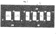
- FIG. 3 another embodiment of a crystallization block 16 for conducting the method for preparing a purified styrene composition in accordance with the present invention is shown.
- the first dynamic melt crystallization section 34 comprises four falling film crystallization stages 36a, 36b, 36c, 36d and the second static melt crystallization section 38 includes two static melt crystallization stages 40a, 40b.
- transfer conduits 52a, 52b, 52c between the falling film crystallization stages 36a, 36b, 36c, 36d, through which a styrene depleted residue fraction obtained by falling film crystallization in the single falling film crystallization stages 36a, 36b, 36c, 36d can be transferred from one of the falling film crystallization stages 36b, 36c, 36d to the respective upstream falling film crystallization stages 36a, 36b, 36c.
- the falling film crystallization stages 36a, 36b, 36c, 36d are connected via recycle conduits 54a, 54b, 54c suitable for recycling at least a part of the styrene enriched crystallized fractions obtained by falling film crystallization in the single falling film crystallization stages 36a, 36b, 36c, 36d from one of the falling film crystallization stages 36a, 36b, 36c to the respective downstream falling film crystallization stages 36b, 36c, 36d.
- An inlet conduit 26 for the side hydrocarbon stream obtained in the divided-wall column is connected to the second falling film crystallization stage 36b such that a crude styrene containing composition can be introduced into the second falling film crystallization stage 36b.
- a discharge conduit 44 is provided at the most downstream falling film crystallization stage 36d in order to remove the purified styrene composition from the crystallization block 16.
- a transfer conduit 46 provides a fluid communication between the most upstream falling film crystallization stage 36a of the first dynamic melt crystallization section 34 and the most upstream static melt crystallization stage 40b of the second static melt crystallization section 38 so that the styrene depleted residue fraction obtained by the crystallization in the falling film crystallization stage 36a can be transferred into the static crystallizer 40b of the second static melt crystallization section 38.
- the static melt crystallization stages 40a and 40b are connected via a transfer conduit 56 for transferring the styrene depleted residue fraction obtained by crystallization from the static melt crystallization stage 40b to the static melt crystallization stage 40a.
- the static melt crystallization stage 40a and the static melt crystallization stage 40b are connected via a recycle conduit 58 allowing for transferring the styrene enriched crystallized fraction, which results from the crystallization in the static melt crystallization stage 40a, into the static melt crystallizer of the crystallization stage 40b.
- the static melt crystallization stage 40a comprises a discharge conduit 48 for discharging the styrene depleted residue fraction, which is obtained by crystallization in the static melt crystallization stage 40a, from the crystallization block 38.
- a recycle conduit 50 provides a fluid communication between the static melt crystallization stage 40b and the falling film crystallization stage 36a and therefore allows to recycle at least a part of the styrene enriched crystallized fraction obtained in the static melt crystallization stage 40b of the second static melt crystallization section 38 back into the falling film crystallization stage 36a of the first dynamic melt crystallization section 34.
- a side hydrocarbon stream obtained in the divided-wall column is fed into the falling film crystallization stage 36b via the inlet conduit 26.
- a styrene enriched crystallized composition and a styrene depleted residue fraction are prepared.
- Each of the styrene depleted residue fractions obtained in one of the falling film crystallization stages 36b, 36c, 36d is transferred via the transfer conduits 52a, 52b, 52c to the respective upstream falling film crystallization stage 36a, 36b, 36c.
- each of the styrene enriched fractions obtained in one of the falling film crystallization stages 36a, 36b, 36c is at least partially recycled via the recycle conduits 36a, 36b, 36c to the respective downstream falling film crystallization stage 36b, 36c, 36d.
- the styrene depleted residue fraction obtained after the crystallization in the falling film crystallization stage 36a of the first dynamic melt crystallization section 34 is transferred via the transfer conduit 46 into the static melt crystallization stage 40b of the second static melt crystallization section 38.
- the styrene depleted residue fraction obtained in the static melt crystallization stage 40b is transferred via the transfer conduit 56 to the downstream static melt crystallization stage 40a.
- the styrene enriched crystallized fraction obtained in the static melt crystallization stage 40a is at least partially recycled via the recycle conduit 58 into the upstream static melt crystallization stage 40b.
- the styrene enriched crystallized fraction obtained after the crystallization in the static melt crystallization stage 40b is recycled via the recycle conduit 50 into the falling film crystallization stage 36a of the first dynamic melt crystallization section 34.
- a finally purified styrene composition obtained in the crystallization stage 36d is removed from the crystallization block 16 via the discharge conduit 44, while the final styrene depleted residue fraction is removed from the static melt crystallization stage 40a and from the crystallization block 16 via the discharge conduit 48.
- Table 2 lists the different impurities that can be typically present in a crude hydrocarbon stream containing styrene and in the side hydrocarbon stream obtained in the divided-wall column with their melting points.
- the reason for impurities removal from side hydrocarbon stream obtained in the divided-wall column by crystallization block 16 is twofold: a) Some of the species have melting points lower than styrene and b) during the crystallization process, impurities which have higher melting point are more soluble in the mother liquor. Thus, despite having a higher melting point, these impurities can be removed from styrene by crystallization. Increasing product purity is directly correlated with an increasing number of crystallization stages.
Abstract
The present invention relates to a method for preparing a purified styrene composition, wherein the method comprises the following steps:a) providing a crude hydrocarbon composition containing styrene,b) subjecting the crude hydrocarbon composition provided in step a) to a distillation in a divided-wall column so as to produce an overhead hydrocarbon stream, a bottom hydrocarbon stream and a side hydrocarbon stream andc) subjecting the side hydrocarbon stream obtained in step b) to at least one crystallization step so as to obtain a purified styrene composition.
Description
- The present invention relates to a method for preparing a purified styrene composition from a crude hydrocarbon composition containing styrene as obtained from a pyrolytic or catalytic based waste polystyrene depolymerization unit. Moreover, the present invention relates to a plant, in which the method may be performed.
- Styrene is an important building block for polymers, such as polystyrene, acrylonitrile-butadiene-styrene (ABS)/styrene-acrylonitrile (SAN) resins, styrene-butadiene (SB) copolymer latexes, unsaturated polyester resins, styrene-butadiene rubber (SBR) elastomers and latexes. It is one of the highest volume commodity chemicals traded, and over 30% of annual styrene production is traded internationally. Predominantly, styrene is produced starting with raw materials benzene and ethylene. Benzene is alkylated to produce ethylbenzene (EB), and the EB is converted into styrene via the conventional dehydrogenation process or ethylbenzene/styrene monomer (EBSM) process, respectively, or the propylene oxide/styrene monomer (POSM) process. Typically, styrene plants are located near ethylene crackers due to the gaseous nature of ethylene which makes it relatively difficult to transport as compared to benzene.
- Apart from the on-purpose production route via EBSM/POSM, styrene is also present in hydrocarbon streams, such as pyrolysis gasoline obtained from steam cracking of naphtha, hydrocarbon fraction obtained from waste polystyrene pyrolysis or catalysis, gas oils etc. Styrene extraction from these hydrocarbon streams, although far less in quantity as compared to EBSM/POSM, presents an attractive economic opportunity to the operator due to the low feedstock cost. The area of styrene production from waste polystyrene has especially gained mainstream attention due to the plastics recycling issues being encountered in the world presently. Waste plastics pose a serious threat to the environment. However, this separation is technically difficult due to the presence of close boiling molecules and impurities coming from the starting feedstock. For instance, during polystyrene recycling different sorts of waste polystyrene are fed into the catalytic or pyrolysis reactor. Due to the contamination of the waste plastic coupled with production of other close boiler compounds, like benzene, toluene, ethylbenzene, alpha-methyl styrene, cumene, n-propyl benzene etc., produced during the pyrolytic or catalytic step there is a need to have a reliable method to purify this styrene oil to the final ASTM grade styrene specification. However, removal of close boiling molecules, such as mixed xylenes, ethylbenzene, etc., from styrene by normal distillation is an energy intensive process. More specifically, conventional two/three column approaches, such as employed in EBSM derived styrene purification, are not only energy intensive and require a high capital expenditure (CAPEX), but also fails to remove close boiling impurities, like oxygenates, color causing compounds, sulfur species etc. Oxygenates can not only come from the feedstock, but are also produced in the process due to air leakages since these columns are in deep vacuum service (typically about 100 to 300 mbar range). It is a known phenomenon that styrene reacts with oxygen to form oxygenate species, like benzaldehyde, which can violate the Total aldehyde as Benzaldehyde specification. Further, since the source to pyrolytic or catalytic reactor is waste polystyrene, which is sorted from mixed plastics, there is a likelihood, despite exercising control of feedstock input to catalytic or pyrolytic depolymerization reactor, of nitrogenated and chlorinated species also being present in the crude styrene oil produced from depolymerization of waste polystyrene. Such species are considered as bad contaminants for the styrene polymerization process, which is the eventual goal of establishing a true circular economy concept in styrene.
- Considering the above, the objective underlying the present invention is to provide an energy efficient method requiring only a plant with low CAPEX for preparing a purified styrene composition from a styrene containing feed composition from a styrene containing stream produced by pyrolysis of recycled polystyrene or the like, which reliably and efficiently removes impurities, such as color inducing species, sulfur and oxygenates, ethylbenzene, mixed xylenes, propylbenzene, ethyltoluene, alpha-methylstyrene, nitrogenated and chlorinated molecules etc., from the styrene in an energy efficient manner, even if the impurities are contained in a comparable high amount in the styrene containing feed composition, so as to obtain in a cost efficient manner a very pure styrene composition.
- In accordance with the present invention, this object is satisfied by providing a method for preparing a purified styrene composition, wherein the method comprises the following steps:
- a) providing a crude hydrocarbon composition containing styrene,
- b) subjecting the crude hydrocarbon composition provided in step a) to a distillation in a divided-wall column so as to produce an overhead hydrocarbon stream, a bottom hydrocarbon stream and a side hydrocarbon stream and
- c) subjecting the side hydrocarbon stream obtained in step b) to at least one crystallization step so as to obtain a purified styrene composition.
- This solution bases on the surprising finding that by first subjecting a crude hydrocarbon composition containing styrene to a distillation in a divided-wall column so as to produce an overhead hydrocarbon stream, a bottom hydrocarbon stream and a side hydrocarbon stream and then subjecting the side hydrocarbon stream obtained in step b) to at least one crystallization step, not only impurities, such as close boiling color inducing species, sulfur and oxygenates, ethylbenzene, mixed xylenes, propylbenzene, ethyltoluene, alpha-methylstyrene, nitrogenated and chlorinated molecules etc., are reliably and completely or at least nearly completely removed from styrene, even if the impurities are contained in a comparable high amount in the crude hydrocarbon composition, but that the respective process is in addition thereto energy efficient and only requires a plant with comparable low CAPEX. This can be neither achieved by using two or three distillation columns for purifying the crude hydrocarbon stream according to the prior art. Crystallization, on a standalone basis, can remove some, not all, of these impurities directly from the crude styrene oil but the diluted styrene poses very low temperature requirements along with addition of significant purification and residue stages making the solution ineffective, CAPEX and operating expenditure prohibitive. The combination of first subjecting a crude hydrocarbon composition to a distillation in a divided-wall column and then subjecting the side hydrocarbon stream obtained in the divided-wall column to at least one crystallization step overcomes the challenges listed above. More specifically, in the typical approach of using two distillation columns for purifying the crude hydrocarbon stream, the distillation energy requirement is disproportionate between the two distillation columns so that replacing the two distillation columns by a divided-wall column is not at all reasonable. Furthermore, this replacement would not at all solve the problem of removal of close boiling color inducing species, oxygenates, sulfur species, nitrogenated and chlorinated species etc., since these impurities cannot be removed in a desirable high degree from styrene by distillation. In contrast thereto, the present invention relies on the "slipping" of impurities, like ethylbenzene, through the distillation step to an extent that the energy consumption of two separate distillation columns becomes more or less the same or at least essentially the same. In other words, instead of producing by distillation an ultra-pure styrene stream containing for instance 99.8% by weight styrene, the process of the present invention intentionally produces by distillation a less pure styrene stream containing for instance 99.2% by weight styrene, thus letting intentionally "slip" the close boiling point impurities through the distillation step. On account of this reason, the two distillation columns become an excellent case for replacement by a divided-wall column, thus achieving 30% energy and 25% CAPEX savings compared to the conventional plants making use of two separate distillation columns. The so obtained pre-purified styrene stream, which is the side hydrocarbon stream of the divided-wall column obtained in step b), containing the impurities, like color inducing species, oxygenates, ethylbenzene and sulfur species, which are not completely removable by distillation, is then subjected to at least one crystallization step, which not only upgrades the styrene content in the purified styrene composition from say 99.2% by weight to more than 99.8% by weight styrene, but which also removes the close boiling and difficult or unable to be removed by conventional distillation impurities from the purified styrene composition. Thus, for instance ASTM grade styrene may be easily and energy efficiently be produced from a polystyrene derived crude styrene oil. All in all, the process in accordance with the present invention allows to cost efficiently purify a styrene containing composition from impurities and even from impurities having a boiling point close to that of styrene.
- As known in the art, crystallization processes or steps, respectively, may be typically carried out in multiple stages, i.e. in several crystallization stages. In view of this, in the present application a crystallization step is defined as comprising one or more crystallization stages.
- The present invention is not particularly limited concerning the styrene content of the crude hydrocarbon composition provided in step a). Good results are in particular obtained, when the crude hydrocarbon composition provided in step a) contains at least 10% by weight, preferably 30% by weight, preferably at least 50% by weight, still more preferably at least 60% by weight, yet more preferably at least 70% by weight and most preferably at least 80% by weight of styrene.
- In principle, the divided-wall column used in step b) may be any divided-wall column and in particular a top divided-wall column, a middle-divided wall column or a bottom-divided wall column. In a top divided-wall column, the dividing wall extends from the top of the column (to which the wall is connected) downwards over a part of the height of the divided wall column, whereas in a bottom divided-wall column the dividing wall extends from the bottom of the column (to which the wall is connected) upwards over a part of the height of the divided wall column. In contrast thereto, in a middle divided-wall column the dividing wall extends over a part of the height of the divided wall column, but without being connected with the top or bottom, thus having a distance to the top as well as to the bottom of the divided-wall column.
- In accordance with a particular preferred embodiment of the present invention, the crude hydrocarbon composition provided in step a) is subjected in step b) to a distillation in a middle divided-wall column.
- Good results are in particular obtained, when the dividing wall of the middle divided-wall column extends, seen over the height, which is the straight distance between the bottom and the top of the middle divided-wall column, from 10 to 90%, preferably from 20 to 80%, more preferably from 30 to 70% and most preferably from 40 to 60% of the height of the middle divided-wall column. In other words, the dividing wall of the middle divided-wall column has a distance to the top as well as to the bottom of the middle divided-wall column, independently from each other, of at least 10% or of at least 20% or of at least 30% or of at least 40%.
- In a further development of the idea of the present invention, it is proposed that the dividing wall extends in the middle divided-wall column essentially vertically downwards, wherein essentially vertically downwards means that the angle between the dividing wall and the length axis of the middle divided-wall column is at most 20°, preferably at most 10°, more preferably at most 5° and most preferably 0°.
- Moreover, it is preferred that the crude hydrocarbon composition, the divided-wall column and the operation conditions are adjusted so that the overhead hydrocarbon stream obtained in step b) is a C7--hydrocarbon stream, the bottom hydrocarbon stream obtained in step b) is a C9+-hydrocarbon stream and the side hydrocarbon stream obtained in step b) is a styrene containing hydrocarbon stream, i.e. a styrene containing C8-hydrocarbon stream.
- As set out above, it is intended that the distillation in step b) is performed so that a pre-purified styrene containing C8-hydrocarbon stream is obtained as side hydrocarbon stream, but not an ultra-pure styrene containing C8-hydrocarbon stream is obtained as side hydrocarbon stream, in order to adjust the energy consumption of both parts of the divided-wall column, which are separated by the dividing wall, so as to have about the same energy consumption. This is possible, since according to the present invention the remaining impurities and in particular impurities having a boiling point close to that of styrene are separated from the side hydrocarbon stream obtained in step b) by the subsequent at least one crystallization step c).
- In view of this, it is preferred that the side hydrocarbon stream obtained in step b) and subjected in step c) to at least one crystallization step contains at least 80% by weight, preferably at least 90% by weight, more preferably at least 98% by weight and most preferably at least 99% by weight of styrene, but preferably less than 99.8% by weight of styrene, preferably less than 99.5% by weight of styrene and more preferably less than 99.3% by weight of styrene.
- As set out above, the present invention is particularly suitable for purifying a crude hydrocarbon composition containing styrene, which contains as impurities one or more impurities selected from the group consisting of color inducing species, sulfur species, meta- and ortho-xylenes, ethylbenzene, phenylacetylene, cumene, n-propylbenzene, alpha-methylstyrene, ethyltoluene, organo-chlorinated, organo-nitrogenated species and arbitrary mixtures of two or more of the aforementioned impurities. Suitable examples therefore are one or more sulfur species and preferably one or more sulfur species selected from the group consisting of mercaptans, disulfides, thiophenes having a boiling point of 130 to 150°C and arbitrary combinations of two or more thereof. Other suitable examples therefore are one or more color inducing species comprising at least one of conjugated diolefins, oxygenated species and oxygenated sulfur species. For instance, the oxygenated species may be water, an alcohol, a ketone and/or a aldehyde, whereas fulvenes and their derivatives are suitable examples for diolefins.
- Preferably, the total content of the aforementioned impurities in the crude hydrocarbon composition is 1 to 60% by weight and more preferably 1 to 40% by weight.
- As set out above, it is intended that after the distillation in step b) in the pre-purified styrene containing C8-hydrocarbon stream, which is obtained as side hydrocarbon stream, still impurities and in particular the aforementioned impurities are contained to a certain extent. Therefore, it is preferred according to the present invention that also the side hydrocarbon stream obtained in step b) and subjected to distillation in step c) contains one or more of the aforementioned impurities, i.e. impurities selected from the group consisting of color inducing species, sulfur species, meta- and ortho-xylenes, ethylbenzene, phenylacetylene, cumene, n-propylbenzene, alpha-methylstyrene, ethyltoluene, organo-chlorinated, organo-nitrogenated species and arbitrary mixtures of two or more of the aforementioned impurities. Preferred impurities are one or more sulfur species and preferably one or more sulfur species selected from the group consisting of mercaptans, disulfides, thiophenes having a boiling point of 130 to 150°C and arbitrary combinations of two or more thereof, and/or one or more color inducing species comprising at least one of conjugated diolefins, oxygenated species, and oxygenated sulfur species, such as water, one or more alcohols, one or more ketones, one or more aldehydes, one or more fulvenes and arbitrary combinations of two or more thereof.
- Preferably, the total content of the aforementioned impurities in the side hydrocarbon stream obtained in step b) and subjected to distillation in step c) is 0.1 to 10% by weight and more preferably 0.7 to 5% by weight.
- Concerning the kind of crystallization technique, the present invention is not particularly limited. Thus, the at least one crystallization step preferably comprises at least one static crystallization stage and/or at least one dynamic crystallization stage and more preferably at least one static melt crystallization stage and/or at least one dynamic melt crystallization stage.
- In accordance with a particular preferred embodiment of the present invention, the at least one crystallization step comprises at least one static melt crystallization stage and at least one dynamic melt crystallization stage.
- Good results are in particular obtained, when the at least one dynamic crystallization stage is a falling film crystallization stage and more preferably a falling film melt crystallization stage. However, instead or in addition to a falling film crystallization stage also a suspension crystallization stage and more preferably a suspension melt crystallization stage may be used.
- In a further development of the idea of the present invention, it is suggested that the method comprises a crystallization step, which comprises one to ten static crystallization stages and one to ten dynamic crystallization stages. Even more preferably, the method comprises a crystallization step, which comprises one to five static crystallization stages and one to five dynamic crystallization stages. If the method comprises two or more dynamic crystallization stages and/or two or more static crystallization stages, each of the dynamic crystallization stages is fluidly coupled with one or two other dynamic crystallization stages, each of the static crystallization stages is fluidly coupled with one or two other static crystallization stages and one of the dynamic crystallization stages is fluidly coupled with one of the static crystallization stages. In other words the dynamic crystallization stages are arranged in series to each other and the static crystallization stages are arranged in series to each other. The numbering starts from the static crystallization stage and the dynamic crystallization stage, which are fluidly coupled together. Thus, if the crystallization comprises four dynamic crystallization stages and four static crystallization stages, the first dynamic crystallization stage and the first static crystallization stage are those, which are coupled with each other. The first dynamic crystallization stage is fluidly coupled with the second dynamic crystallization stage, which is coupled with the third dynamic crystallization stage, wherein the third dynamic crystallization stage is coupled with the fourth dynamic crystallization stage. Likewise thereto, the first static crystallization stage is fluidly coupled with the second static crystallization stage, which is coupled with the third static crystallization stage, wherein the third static crystallization stage is coupled with the fourth static crystallization stage. In both series, the first crystallization stage is the most upstream crystallization stage, wherein the second, third and fourth crystallization stages are located downstream of the first crystallization stage in series to each other.
- In accordance with a first particular preferred embodiment of the present invention, the method comprises a crystallization step, which comprises one static crystallization stage and one dynamic crystallization stage. In this variant, the side hydrocarbon stream obtained in step b) and subjected in step c) to the at least one crystallization step is preferably fed into the dynamic crystallization stage so as to produce a styrene enriched crystallized fraction and a styrene depleted residue fraction. The styrene depleted residue fraction obtained in the dynamic crystallization stage mainly contains the styrene depleted mother liquor and is fed into the static crystallization stage as mother liquor. Also in the static crystallization stage a styrene enriched crystallized fraction and a styrene depleted residue fraction are produced, wherein the styrene enriched crystallized fraction obtained in the static crystallization stage is fed into the dynamic crystallization stage and mixed there with the side hydrocarbon stream fed into the dynamic crystallization stage. The styrene depleted residue fraction obtained in the static crystallization stage is withdrawn, whereas the styrene enriched crystallized fraction obtained in the dynamic crystallization stage is withdrawn as the purified styrene composition. In principle, the side hydrocarbon stream obtained in step b) may be alternatively to the above described embodiment fed into the static crystallization stage, i.e. the static crystallization and dynamic crystallization stages may be arranged in reversed order to the aforementioned description. However, better results are obtained, when the side hydrocarbon stream obtained in step b) is fed into the dynamic crystallization stage. For the sake of completeness, it is noted that the aforementioned terms "styrene enriched crystallized fraction" and "styrene depleted residue fraction" are meant relative to the styrene content of the input into the respective crystallization stage and not relative to the styrene content of the side hydrocarbon stream obtained in step b). In other words, the styrene enriched crystallized fraction obtained in the static crystallization stage has a higher styrene content than the input into this static crystallization stage (which is the styrene depleted residue fraction fed from the dynamic crystallization stage into the static crystallization stage) and the styrene depleted residue fraction has a lower styrene content than the input into this static crystallization stage.
- In accordance with a second particular preferred embodiment of the present invention, the method comprises a crystallization step, which comprises two to five static crystallization stages and two to five dynamic crystallization stages. Preferably, the side hydrocarbon stream obtained in step b) and subjected in step c) to the at least one crystallization step is fed into the first of the two to five dynamic crystallization stages so as to produce a first styrene enriched crystallized fraction and a first styrene depleted residue fraction, wherein the first styrene enriched crystallized fraction is fed into the second of the two to five dynamic crystallization stages, wherein in any of the second and of the optional third to fifth dynamic crystallization stages a styrene enriched crystallized fraction and a styrene depleted residue fraction is produced, wherein each of the styrene enriched crystallized fractions produced in the second and the optional third to fourth dynamic crystallization stages is fed into a downstream dynamic crystallization stage and each of the styrene depleted residue fractions produced in the second and the optional third to fifth dynamic crystallization stages is fed into an upstream dynamic crystallization stage. The first styrene depleted residue fraction is fed into the first of the two to five static crystallization stages so as to produce a second styrene enriched crystallized fraction and a second styrene depleted residue fraction, wherein the second styrene enriched crystallized fraction is fed into the first dynamic crystallization stage and the second styrene depleted residue fraction is fed into the second of the two to five static crystallization stages. In any of the second and of the optional third to fifth static crystallization stages a styrene enriched crystallized fraction and a styrene depleted residue fraction is produced, wherein each of the styrene depleted residue fractions produced in the second and the optional third to fourth static crystallization stages is fed into a downstream static crystallization stage and each of the styrene enriched crystallized fractions produced in the second and the optional third to fifth dynamic static stages is fed into an upstream static crystallization stage. In principle, the side hydrocarbon stream obtained in step b) and subjected in step c) to the at least one crystallization step may be fed into one of the static crystallization stages, i.e. the static crystallization and dynamic crystallization stages may be arranged in reversed order to the aforementioned description. However, better results are obtained, when the side hydrocarbon stream obtained in step b) is fed into one of the dynamic crystallization stage.
- In an alternative variant to the aforementioned described variant, the side hydrocarbon stream obtained in step b) and subjected in step c) to the at least one crystallization step is fed into the second of the two to five dynamic crystallization stages and not into the first dynamic crystallization stage, wherein first to fifth is again seen in the direction upstream to downstream. Again, the most upstream dynamic crystallization stage (i.e. the first dynamic crystallization stage) is that, which receives a styrene enriched crystallized fraction from the first static crystallization stage and from which a styrene depleted residue fraction is fed into the first static crystallization stage, whereas the most downstream dynamic crystallization stage is that, from which the purified styrene composition is withdrawn. Likewise, the most upstream static crystallization stage (i.e. the first static crystallization stage) is that, which receives a styrene depleted residue fraction from the first dynamic crystallization stage and from which a styrene enriched crystallized fraction is fed into the first dynamic crystallization stage, whereas the most downstream static crystallization stage (i.e. the second static crystallization stage) is that, from which the styrene depleted residue fraction is withdrawn.
- For instance, the method comprises a crystallization step, which comprises two static crystallization stages and four dynamic crystallization stages. In this embodiment, the side hydrocarbon stream obtained in step b) and subjected in step c) to the at least one crystallization step is fed into the second of the dynamic crystallization stages so as to produce a second styrene enriched crystallized fraction and a second styrene depleted residue fraction. The second styrene enriched crystallized fraction is fed into the third of the four dynamic crystallization stages so as to produce a third styrene enriched crystallized fraction and a third styrene depleted residue fraction, wherein the third styrene enriched crystallized fraction is fed into the fourth of the dynamic crystallization stages so as to produce a fourth styrene enriched crystallized fraction and a fourth styrene depleted residue fraction. While the fourth styrene enriched crystallized fraction is withdrawn as purified styrene composition, the fourth styrene depleted residue fraction is fed into the third dynamic crystallization stage, the third styrene depleted residue fraction is fed into the second dynamic crystallization stage and the second styrene depleted residue fraction is fed into the first dynamic crystallization stage. In the first dynamic crystallization stage, a first styrene enriched crystallized fraction and a first styrene depleted residue fraction are produced. While the first styrene enriched crystallized fraction is fed into the second dynamic crystallization stage, the first styrene depleted residue fraction is fed into the first of the two static crystallization stages, in which a fifth styrene enriched crystallized fraction and a fifth styrene depleted residue fraction are produced. While the fifth styrene enriched crystallized fraction is fed into the first dynamic crystallization stage, the fifth styrene depleted residue fraction is fed into the second of the two static crystallization stages, in which a sixth styrene enriched crystallized fraction and a sixth styrene depleted residue fraction are produced. While the sixth styrene enriched crystallized fraction is fed into the first static crystallization stage, the sixth styrene depleted residue fraction is removed.
- In all of the above described methods, preferably the production of a styrene enriched crystallized fraction and of a styrene depleted residue fraction in a crystallization stage comprises the steps of removing the remaining liquid from the crystallization stage as styrene depleted residue fraction after termination of the crystallization in the crystallization stage, of melting the crystal layer obtained in the crystallization stage and of withdrawing the obtained crystal melt as styrene enriched crystallized fraction from the crystallization stage.
- In order to increase the purity of the purified styrene product, it is preferable to perform in any of the crystallization stages at least one sweating step before melting the crystal layers formed on the cooled surfaces of the crystallizer used in the single crystallization stages. Sweating means that the crystal layer deposited on the cooled surfaces are gently heated to a temperature close to the melting temperature of styrene in order to partially melt the crystals. Trapped and adherent melt, which contains the impurities, drains off during the partial melting of the crystals and is then removed from the crystallizer. In order to conduct such a sweating, the surface, on which the crystals are deposited, is heated with a heat transfer medium to the desired temperature. The sweating may be performed for one or several times before melting the crystal layers deposited on the cooled surfaces. Thus, the sweating leads to one or more sweating fractions and to a purified crystal layer. Preferably, at least a portion of the first sweating fraction obtained thereby is fed to the remaining liquid which has been removed as styrene depleted residue fraction.
- The crystallization temperature depends on the composition of the side hydrocarbon stream obtained in step b). However, good results are obtained, when at least one and preferably all of the at least one static melt crystallization stage and/or of the at least one dynamic melt crystallization stage are performed at a temperature of -200°C and 30°C, preferably at a temperature of -140°C and 0°C and more preferably at a temperature of -100°C and -30°C.
- As set out above, the present invention is particularly suitable for purifying as crude hydrocarbon composition a pygas. In particular, pygas obtained by pyrolyzing recycled polystyrene is suitable as crude hydrocarbon composition. The process of the present invention allows to cost efficiently purify styrene from such feed compositions, which is not possible with the prior art methods.
- The method in accordance with the present invention results in a very pure styrene containing composition. Preferably, the purified styrene composition has a styrene content of at least 99.00% by weight, more preferably of at least 99.50% by weight, even more preferably of at least 99.80% by weight, still more preferably of at least 99.90% by weight, yet more preferably of at least 99.95% by weight and most preferably of at least 99.98% by weight.
- In particular, the method in accordance with the present invention allows to completely or at least nearly completely remove color inducing species from the crude styrene containing composition. Therefore, in a further development of the idea of the present invention, it is proposed that the purified styrene composition has a color of maximum 15 as defined by Pt-Co scale as per ASTM D5386.
- Furthermore, the method in accordance with the present invention allows to completely or at least nearly completely remove sulfur species from the crude styrene containing composition. Consequently, it is in particular preferred, when the purified styrene composition comprises less than 2 ppmw of total elemental sulfur as contained in mercaptans, disulfides and thiophenes and/or less than 20 ppmw of oxygenates.
- In addition, the method in accordance with the present invention allows to obtain purified styrene composition, which comprises less than 40 ppmw of impurities selected from the group consisting of phenylacetylene, mixed xylenes, ethylbenzene, cumene, ethyltoluene, n-propylbenzene, and alpha-methylstyrene, and/or which has polymer content of less than 10 ppmw.
- Preferably, the purified styrene composition has total organic chlorine content of less than 2 ppmw.
- For instance, the purified styrene composition may meet the following specifications.
Table 1 Parameter Unit Specification Test Method Color Pt/Co scale 15 max. ASTM D5386 Styrene monomer purity Wt% 99.8 min. ASTM D5135 or 7504 Aldehydes as benzaldehyde Wt ppm 75 max. ASTM D2119 Peroxides as H2O2 Wt ppm 15 max. ASTM D2340 Polymer content Wt ppm 10 max. ASTM D2121 Test Method A Inhibitor (tert-butylcatechol) Wt ppm 10 max. ASTM D4590 Ethylbenzene Wt ppm 500 max. ASTM D5135 or D7504 Benzene Wt ppm 1 max. ASTM D6229 Phenylacetylene Wt ppm 150 max. ASTM D5135 Water Wt ppm 50 max. ASTM E1064 Total organic Chlorides Wt ppm 2 max. ASTM D5808 Copper and Manganese Wt ppm 5 max. UOP 389 or 407 Viscosity at 25°C cP 0.75 max. Appearance - Clear, transparent liquid free of sediment and haze at 18 to 25°C - According to a further aspect, the present invention relates to a plant for preparing a purified styrene composition comprising at least one divided-wall column and at least one crystallization block, wherein the divided-wall column comprises an inlet line for a crude hydrocarbon composition containing styrene, a line for overhead hydrocarbon stream, a line for bottom hydrocarbon stream and a line for a side hydrocarbon stream, wherein the at least one crystallization block comprises an inlet line, wherein the line for a side hydrocarbon stream of the divided-wall column leads to (or is connected with or is, respectively) the inlet line of the at least one crystallization block.
- Preferably, the divided-wall column is a middle divided-wall column. Good results are in particular obtained, when the dividing wall of the middle divided-wall column extends, seen over the height, which is the straight distance between the bottom and the top of the middle divided-wall column, essentially vertically downwards from 10 to 90%, preferably from 20 to 80%, more preferably from 30 to 70% and most preferably from 40 to 60% of the height of the middle divided-wall column, wherein essentially vertically downwards means that the angle between the dividing wall and the length axis of the middle divided-wall column is at most 20°, preferably at most 10°, more preferably at most 5° and most preferably 0°.
- In a further development of the idea of the present invention it is suggested that the plant further comprises a pyrolysis or catalytic reactor unit block comprising an inlet line and an outlet line, wherein the outlet line of the pyrolysis or catalytic reactor unit block leads into (or is connected with or is, respectively) the inlet line of the divided-wall column.
- In accordance with a particular preferred embodiment of the present invention, the at least one crystallization block comprises:
at least one static crystallization section comprising one or more static crystallization stages, at least one dynamic crystallization section comprising one or more dynamic crystallization stages and at least two conduits that fluidly couple at least one of the one or more static crystallization stages with at least one of the one or more dynamic crystallization stages. - The term "crystallization block" refers to an apparatus for a purification process with one or more crystallizers. Moreover, the term crystallization stage is not only used to denote a method step or stage, respectively, but also to denote an apparatus, namely that part of a crystallizer, in which a crystallization stage is performed. The crystallization stage as apparatus feature may be also designated as crystallizer, crystallizer unit or the like.
- Preferably, the one or more static crystallization stages are static melt crystallization stages and the one or more dynamic crystallization stages are dynamic melt crystallization stages.
- If the crystallization block comprises two or more dynamic crystallization stages and/or two or more static crystallization stages, preferably each of the dynamic crystallization stages is fluidly coupled with one or two other dynamic crystallization stages and each of the static crystallization stages is fluidly coupled with one or two other static crystallization stages.
- Moreover, it is preferred that the at least one crystallization block comprises one static crystallization stage and one dynamic crystallization stage, wherein one of the at least two conduits fluidly couples the static crystallization stage with the dynamic crystallization stage so that a styrene depleted residue fraction obtained in the dynamic crystallization stage may be fed into the static crystallization stage, and wherein one other of the at least two conduits fluidly couples the static crystallization stage with the dynamic crystallization stage so that a styrene enriched crystallized fraction obtained in the static crystallization stage may be fed into the dynamic crystallization stage.
- Moreover, it is preferred that the at least one crystallization block comprises two to five static crystallization stages and two to five dynamic crystallization stages, wherein one of the at least two conduits fluidly couples one of the static crystallization stages with one of the dynamic crystallization stages so that a styrene depleted residue fraction obtained in the dynamic crystallization stage may be fed into the static crystallization stage being fluidly coupled with the dynamic crystallization stage, and wherein one of the at least two conduits fluidly couples the static crystallization stage with the dynamic crystallization stage being fluidly coupled with the static crystallization stage so that a styrene enriched crystallized fraction obtained in the static crystallization stage may be fed into the dynamic crystallization stage, wherein each two of the remaining static crystallization stages are fluidly coupled with each other by means of at least two conduits, and wherein each two of the remaining dynamic crystallization stages are fluidly coupled with each other by means of at least two conduits.
- In order that the manner in which the above recited and other advantages and objects of the invention are obtained, a more particular description of the invention briefly described above will be rendered by reference to specific embodiments thereof, which are illustrated, in the appended drawings. Understanding that these drawings depict only typical embodiments of the invention and are therefore not to be considered limiting of its scope, the invention will be described with additional specificity and detail through the use of the accompanying drawings in which:
- FIG. 1
- is a diagrammatic illustration of a plant in accordance with one embodiment of the present invention.
- FIG. 2
- is a diagrammatic illustration of a crystal block used in a method and plant in accordance with one embodiment of the present invention.
- FIG. 3
- is a diagrammatic illustration of a crystal block used in a method and plant in accordance with another embodiment of the present invention.
-
FIG. 1 shows aplant 10 particularly suitable for purifying a styrene containing stream produced from a recycled polystyrene stream via pyrolysis. Theplant 10 comprises a pyrolysis or catalyticreactor unit block 12, a divided-wall column 14 and acrystallization block 16. The pyrolysis or catalyticreactor unit block 12 comprises aninlet line 18 for feed, such as for a stream made of recycled polystyrene and an outlet line for pyrolysis product, which is simultaneously theinlet line 20 for crude hydrocarbon stream containing styrene. The divided-wall column 14 is a middle divided-wall column 14, wherein the dividingwall 28 of the middle divided-wall column 14 extends, seen over the height, which is the straight distance between the bottom and the top of the middle divided-wall column 14, vertically downwards from about 25% to about 75% of the height of the middle divided-wall column. The divided-wall column 14 comprises aline 22 for overhead hydrocarbon stream, aline 24 for bottom hydrocarbon stream and aline 26 for side hydrocarbon stream, wherein theline 26 for side hydrocarbon stream is the inlet line to thecrystallization block 16. Thecrystallization block 16 comprises adischarge conduit 30 for styrene depleted residue fraction and adischarge conduit 32 for purified styrene composition. Thecrystallization block 16 might be composed as that shown inFIG. 2 or that as shown inFIG. 3 . - During the operation, the pyrolysis of polystyrene is performed in the pyrolysis or catalytic
reactor unit block 12, which may be operated thermally or in a catalytic mode. The effluent from the pyrolysis or catalyticreactor unit block 12 contains styrene and a plurality of impurities and is fed via theline 20 as crude hydrocarbon stream containing styrene into the middle divided-wall column 14. In the middle divided-wall column 14, the mixture is divided into a C9+-hydrocarbon stream obtained as bottom hydrocarbon stream and withdrawn vialine 24, a C7--hydrocarbon stream obtained as top hydrocarbon stream and withdrawn vialine 22 as well as a styrene containing C8-hydrocarbon stream 26 obtained as side hydrocarbon stream and withdrawn vialine 26. The side hydrocarbon stream is fed vialine 26 into thecrystallization block 16, where it is crystallized. During the crystallization, the impurities and in particular the color inducing species, sulfur species, oxygenates and impurities having a boiling point close to that of styrene, such as ethylbenzene, are reliably and nearly completely removed and withdrawn styrene depleted residue fraction vialine 30, whereas the purified styrene composition is withdrawn vialine 32. -
FIG. 2 shows an embodiment of acrystallization block 16 for conducting the process for preparing a purified styrene composition and as included in the plant in accordance with an embodiment of the present invention, such as in a plant as shown inFIG. 1 . Thecrystallization block 16 includes a first dynamicmelt crystallization section 34 which comprises one falling film crystallization stage or one fallingfilm crystallizer 36, respectively as a dynamic melt crystallization stage or crystallizer, respectively. In addition, thecrystallization block 16 comprises a second staticmelt crystallization section 38 having one staticmelt crystallization stage 40 or one static melt crystallizer, respectively. The fallingfilm crystallizer 36 is connected with aninlet conduit 26 for side hydrocarbon stream obtained in the divided-wall column. In addition, the fallingfilm crystallizer 36 has adischarge conduit 44 for the discharge of a purified styrene composition from the fallingfilm crystallizer 36 and from thecrystallization block 16. Thestatic melt crystallizer 40 is connected with the fallingfilm crystallizer 36 via a transfer conduit 46 which is suitable for transferring a first styrene depleted residue fraction obtained by crystallization in the fallingfilm crystallizer 36 into thestatic melt crystallizer 40. With this respect, the transfer conduit 46 is in fluid communication with both the fallingfilm crystallizer 36 and thestatic melt crystallizer 40. Thestatic melt crystallizer 40 comprises adischarge conduit 48 which serves for discharging a second styrene depleted residue fraction, which is obtained by the crystallization in thestatic melt crystallizer 40, from thestatic melt crystallizer 40 and from thecrystallization block 16. Arecycle conduit 50 provides a fluid communication between thestatic melt crystallizer 40 and the fallingfilm crystallizer 36 and therefore allows to recycle at least a part of the second styrene enriched crystallization composition, which results from the crystallization in thestatic melt crystallizer 40, back into the fallingfilm crystallizer 36. - In
FIG. 3 , another embodiment of acrystallization block 16 for conducting the method for preparing a purified styrene composition in accordance with the present invention is shown. The first dynamicmelt crystallization section 34 comprises four fallingfilm crystallization stages melt crystallization section 38 includes two staticmelt crystallization stages 40a, 40b. There are provided transfer conduits 52a, 52b, 52c between the fallingfilm crystallization stages film crystallization stages film crystallization stages film crystallization stages film crystallization stages film crystallization stages inlet conduit 26 for the side hydrocarbon stream obtained in the divided-wall column is connected to the second falling film crystallization stage 36b such that a crude styrene containing composition can be introduced into the second falling film crystallization stage 36b. Adischarge conduit 44 is provided at the most downstream fallingfilm crystallization stage 36d in order to remove the purified styrene composition from thecrystallization block 16. A transfer conduit 46 provides a fluid communication between the most upstream fallingfilm crystallization stage 36a of the first dynamicmelt crystallization section 34 and the most upstream static melt crystallization stage 40b of the second staticmelt crystallization section 38 so that the styrene depleted residue fraction obtained by the crystallization in the fallingfilm crystallization stage 36a can be transferred into the static crystallizer 40b of the second staticmelt crystallization section 38. The staticmelt crystallization stages 40a and 40b are connected via a transfer conduit 56 for transferring the styrene depleted residue fraction obtained by crystallization from the static melt crystallization stage 40b to the staticmelt crystallization stage 40a. In addition, the staticmelt crystallization stage 40a and the static melt crystallization stage 40b are connected via a recycle conduit 58 allowing for transferring the styrene enriched crystallized fraction, which results from the crystallization in the staticmelt crystallization stage 40a, into the static melt crystallizer of the crystallization stage 40b. Furthermore, the staticmelt crystallization stage 40a comprises adischarge conduit 48 for discharging the styrene depleted residue fraction, which is obtained by crystallization in the staticmelt crystallization stage 40a, from thecrystallization block 38. Arecycle conduit 50 provides a fluid communication between the static melt crystallization stage 40b and the fallingfilm crystallization stage 36a and therefore allows to recycle at least a part of the styrene enriched crystallized fraction obtained in the static melt crystallization stage 40b of the second staticmelt crystallization section 38 back into the fallingfilm crystallization stage 36a of the first dynamicmelt crystallization section 34. - During operation of the
crystallization block 16 shown inFIG. 3 a side hydrocarbon stream obtained in the divided-wall column is fed into the falling film crystallization stage 36b via theinlet conduit 26. In each of the fallingfilm crystallization stages film crystallization stage film crystallization stages recycle conduits film crystallization stage film crystallization stage 36a of the first dynamicmelt crystallization section 34 is transferred via the transfer conduit 46 into the static melt crystallization stage 40b of the second staticmelt crystallization section 38. The styrene depleted residue fraction obtained in the static melt crystallization stage 40b is transferred via the transfer conduit 56 to the downstream staticmelt crystallization stage 40a. In addition, the styrene enriched crystallized fraction obtained in the staticmelt crystallization stage 40a is at least partially recycled via the recycle conduit 58 into the upstream static melt crystallization stage 40b. The styrene enriched crystallized fraction obtained after the crystallization in the static melt crystallization stage 40b is recycled via therecycle conduit 50 into the fallingfilm crystallization stage 36a of the first dynamicmelt crystallization section 34. A finally purified styrene composition obtained in thecrystallization stage 36d is removed from thecrystallization block 16 via thedischarge conduit 44, while the final styrene depleted residue fraction is removed from the staticmelt crystallization stage 40a and from thecrystallization block 16 via thedischarge conduit 48. - In accordance with the present invention, Table 2 lists the different impurities that can be typically present in a crude hydrocarbon stream containing styrene and in the side hydrocarbon stream obtained in the divided-wall column with their melting points. The reason for impurities removal from side hydrocarbon stream obtained in the divided-wall column by
crystallization block 16 is twofold: a) Some of the species have melting points lower than styrene and b) during the crystallization process, impurities which have higher melting point are more soluble in the mother liquor. Thus, despite having a higher melting point, these impurities can be removed from styrene by crystallization. Increasing product purity is directly correlated with an increasing number of crystallization stages. Recovery, on the other hand, is a function of the number of residue stages.Table 2 COMPOUND MELTING POINT Water 0°C (32 °F; 273 K) α-Methylstyrene -23°C (-9.4 °F; 250 K) o-Xylene -25.2°C (-13.4 °F; 248 K) Benzaldehyde -26°C (-14.8 °F; 247 K) Styrene -30.6°C (-23.1 °F; 243 K) Thiophenic compounds boiling in the range 130-150°C -65 to -30°C (-85 to -22 °F; 208 to 243 K) Phenylacetylene -45°C (-49 °F; 228 K) Ethylbenzene -95°C (-139 °F; 178 K) 3-Ethyltoluene (m-ethyltoluene) -95.5°C (-140 °F; 177.6 K) Cumene -96°C (-141 °F; 177 K) n-Propylbenzene -99.5°C (-147 °F; 173.7 K) -
- 10
- Plant for preparing a purified styrene composition
- 12
- Pyrolysis or catalytic reactor unit block
- 14
- (Middle) divided-wall column
- 16
- Crystallization block
- 18
- Inlet line for feed
- 20
- Outlet line for pyrolysis product / Inlet line for crude hydrocarbon stream containing styrene
- 22
- Line for overhead hydrocarbon stream
- 24
- Line for bottom hydrocarbon stream
- 26
- Line for side hydrocarbon stream
- 28
- Dividing wall of divided-wall column
- 30
- Discharge conduit for styrene depleted residue fraction
- 32
- Discharge conduit for purified styrene composition
- 34
- First dynamic melt crystallization section
- 36
- Dynamic (falling film) melt crystallizer/crystallization stage
- 36a, 36b, 36c, 36d
- Dynamic melt / falling film crystallization stages
- 38
- Second static melt crystallization section
- 40
- Static melt crystallizer/crystallization stage
- 40a, 40b
- Static melt crystallization stages
- 44
- Discharge conduit for purified styrene composition
- 46
- (Transfer) conduit for feeding a styrene depleted residue fraction from the dynamic crystallization section to the static crystallization section
- 48
- Discharge conduit for styrene depleted residue fraction
- 50
- (Recycle) conduit for feeding a styrene enriched fraction from the static crystallization section to the dynamic crystallization section
- 52a, 52b, 52c
- Conduits for styrene depleted residue fractions in the dynamic crystallization section
- 54a, 54b, 54c
- Conduits for styrene enriched crystallized fraction in the dynamic crystallization section
- 56
- Conduit for styrene depleted residue fractions in the static crystallization section
- 58
- Conduit for styrene enriched crystallized fraction in the static crystallization section
Claims (15)
- A method for preparing a purified styrene composition, wherein the method comprises the following steps:a) providing a crude hydrocarbon composition containing styrene,b) subjecting the crude hydrocarbon composition provided in step a) to a distillation in a divided-wall column (14) so as to produce an overhead hydrocarbon stream, a bottom hydrocarbon stream and a side hydrocarbon stream andc) subjecting the side hydrocarbon stream obtained in step b) to at least one crystallization step so as to obtain a purified styrene composition.
- The method of claim 1, wherein the crude hydrocarbon composition provided in step a) is subjected in step b) to a distillation in a middle divided-wall column (14).
- The method of claim 1 or 2, wherein the overhead hydrocarbon stream obtained in step b) is a C7--hydrocarbon stream, the bottom hydrocarbon stream obtained in step b) is a C9+-hydrocarbon stream and the side hydrocarbon stream obtained in step b) is a styrene containing hydrocarbon stream.
- The method of any of the preceding claims, wherein the side hydrocarbon stream obtained in step b) and subjected in step c) to at least one crystallization step contains at least 80% by weight, preferably at least 90% by weight, more preferably at least 98% by weight and most preferably at least 99% by weight of styrene.
- The method of any of the preceding claims, wherein the crude hydrocarbon composition provided in step a) as well as the side hydrocarbon stream obtained in step b) contain one or more impurities selected from the group consisting of color inducing species, sulfur species, meta- and ortho-xylenes, ethylbenzene, phenylacetylene, cumene, n-propylbenzene, alpha-methylstyrene, ethyltoluene, organo-chlorinated, organo-nitrogenated species and arbitrary mixtures of two or more of the aforementioned impurities.
- The method of claim 5, wherein the crude hydrocarbon composition provided in step a) as well as the side hydrocarbon stream obtained in step b) contain as impurities one or more sulfur species and preferably one or more sulfur species selected from the group consisting of mercaptans, disulfides, thiophenes having a boiling point of 130 to 150°C and arbitrary combinations of two or more thereof.
- The method of claim 5 or 6, wherein the crude hydrocarbon composition provided in step a) as well as the side hydrocarbon stream obtained in step b) contain as impurities comprise one or more color inducing species comprising at least one of conjugated diolefins, oxygenated species, and oxygenated sulfur species.
- The method of any of the preceding claims, wherein the at least one crystallization step comprises at least one static melt crystallization stage and at least one dynamic melt crystallization stage, wherein preferably the at least one dynamic crystallization stage is a falling film melt crystallization stage.
- The process according to any of the preceding claims, wherein the crude hydrocarbon composition provided in step a) is a pygas and preferably has been obtained by pyrolyzing an ethylbenzene and styrene containing stream produced in an ethyl-benzene/styrene monomer (EBSM) process, by pyrolyzing a hydrocarbon stream obtained in a naphtha cracker or by pyrolyzing polystyrene, preferably recycled polystyrene.
- The method of any of the preceding claims, wherein the purified styrene composition has a styrene content of at least 99.00% by weight, preferably of at least 99.50% by weight, more preferably of at least 99.80% by weight, still more preferably of at least 99.90% by weight, yet more preferably of at least 99.95% by weight and most preferably of at least 99.98% by weight.
- The method of any of the preceding claims, wherein the purified styrene composition fulfils one or more of the below criteria.i) has a color of maximum 15 as defined by Pt-Co scale as per ASTM D5386,ii) comprises less than 2 ppmw of total elemental sulfur as contained in mercaptans, disulfides and thiophenes,iii) comprises less than 20 ppmw of oxygenates,iv) comprises less than 40 ppmw of impurities selected from the group consisting of phenylacetylene, mixed xylenes, ethylbenzene, cumene, ethyltoluene, n-propylbenzene, and alpha-methylstyrene,v) has polymer content of less than 10 ppmw,vi) has total organic chlorine content of less than 2 ppmw.
- A plant (10) for preparing a purified styrene composition comprising at least one divided-wall column (14) and at least one crystallization block (16), wherein the divided-wall column (14) comprises an inlet line (20) for a crude hydrocarbon composition containing styrene, a line for overhead hydrocarbon stream (22), a line for bottom hydrocarbon stream (24) and a line for side hydrocarbon stream (26), wherein the at least one crystallization block (10) comprises an inlet line (26), wherein the line for side hydrocarbon stream of the divided-wall column (14) is the inlet line (26) of the at least one crystallization block (10).
- The plant (10) of claim 12, wherein the divided-wall column (14) is a middle divided-wall column (14), wherein the dividing wall (28) of the middle divided-wall column (14) extends, seen over the height, which is the straight distance between the bottom and the top of the middle divided-wall column (14), essentially vertically downwards from 10 to 90%, preferably from 20 to 80%, more preferably from 30 to 70% and most preferably from 40 to 60% of the height of the middle divided-wall column (14), wherein essentially vertically downwards means that the angle between the dividing wall (14) and the length axis of the middle divided-wall column (14) is at most 20°, preferably at most 10°, more preferably at most 5° and most preferably 0°.
- The plant (10) of claim 12 or 13, which further comprises a pyrolysis or catalytic reactor unit block (12) comprising an inlet line (18) and an outlet line (20), wherein the outlet line (20) of the pyrolysis or catalytic reactor unit block (12) is the inlet line (20) of the divided-wall column (14).
- The plant (10) of any of claims 12 to 14, wherein the crystallization block (10) comprises:at least one static crystallization section (38) comprising one or more static crystallization stages (40, 40a, 40b),at least one dynamic crystallization section (34) comprising one or more dynamic crystallization stages (36, 36a, 36b, 36c, 36d) andat least two conduits (46, 50) that fluidly couple at least one of the one or more static crystallization stages (40, 04b) with at least one of the one or more dynamic crystallization stages (36, 36a).
Priority Applications (11)
| Application Number | Priority Date | Filing Date | Title |
|---|---|---|---|
| TW110135847A TW202229213A (en) | 2020-09-30 | 2021-09-27 | A process and apparatus for preparing a purified styrene composition using a divided-wall column and a crystallization unit |
| AU2021353471A AU2021353471A1 (en) | 2020-09-30 | 2021-09-28 | A process and apparatus for preparing a purified styrene composition using a divided-wall column and a crystallization unit |
| PCT/EP2021/076672 WO2022069479A1 (en) | 2020-09-30 | 2021-09-28 | A process and apparatus for preparing a purified styrene composition using a divided-wall column and a crystallization unit |
| EP21782750.0A EP4204387A1 (en) | 2020-09-30 | 2021-09-28 | A process and apparatus for preparing a purified styrene composition using a divided-wall column and a crystallization unit |
| JP2023519614A JP2023544992A (en) | 2020-09-30 | 2021-09-28 | Method and apparatus for preparing purified styrene compositions using a dividing wall column and crystallization unit |
| BR112023005885A BR112023005885A2 (en) | 2020-09-30 | 2021-09-28 | A PROCESS AND APPARATUS FOR PREPARING A PURIFIED STYRENE COMPOSITION USING A SPLIT WALL COLUMN AND A CRYSTALLIZATION UNIT |
| IL301743A IL301743A (en) | 2020-09-30 | 2021-09-28 | A process and apparatus for preparing a purified styrene composition using a divided-wall column and a crystallization unit |
| CN202180066332.8A CN116209649A (en) | 2020-09-30 | 2021-09-28 | Method and apparatus for preparing purified styrene compositions using a divided wall column and crystallization unit |
| US18/029,595 US20230365480A1 (en) | 2020-09-30 | 2021-09-28 | Process and apparatus for preparing purified styrene composition using divided-wall column and crystallization unit |
| KR1020237013862A KR20230074773A (en) | 2020-09-30 | 2021-09-28 | Method and Apparatus for Producing a Purified Styrene Composition Using a Dividing Wall Column and Crystallization Unit |
| CA3191557A CA3191557A1 (en) | 2020-09-30 | 2021-09-28 | A process and apparatus for preparing a purified styrene composition using a divided-wall column and a crystallization unit |
Applications Claiming Priority (1)
| Application Number | Priority Date | Filing Date | Title |
|---|---|---|---|
| US202063085760P | 2020-09-30 | 2020-09-30 |
Publications (1)
| Publication Number | Publication Date |
|---|---|
| EP3978461A1 true EP3978461A1 (en) | 2022-04-06 |
Family
ID=72801419
Family Applications (2)
| Application Number | Title | Priority Date | Filing Date |
|---|---|---|---|
| EP20200620.1A Withdrawn EP3978461A1 (en) | 2020-09-30 | 2020-10-07 | A process and apparatus for preparing a purified styrene composition using a divided-wall column and a crystallization unit |
| EP21782750.0A Pending EP4204387A1 (en) | 2020-09-30 | 2021-09-28 | A process and apparatus for preparing a purified styrene composition using a divided-wall column and a crystallization unit |
Family Applications After (1)
| Application Number | Title | Priority Date | Filing Date |
|---|---|---|---|
| EP21782750.0A Pending EP4204387A1 (en) | 2020-09-30 | 2021-09-28 | A process and apparatus for preparing a purified styrene composition using a divided-wall column and a crystallization unit |
Country Status (11)
| Country | Link |
|---|---|
| US (1) | US20230365480A1 (en) |
| EP (2) | EP3978461A1 (en) |
| JP (1) | JP2023544992A (en) |
| KR (1) | KR20230074773A (en) |
| CN (1) | CN116209649A (en) |
| AU (1) | AU2021353471A1 (en) |
| BR (1) | BR112023005885A2 (en) |
| CA (1) | CA3191557A1 (en) |
| IL (1) | IL301743A (en) |
| TW (1) | TW202229213A (en) |
| WO (1) | WO2022069479A1 (en) |
Citations (2)
| Publication number | Priority date | Publication date | Assignee | Title |
|---|---|---|---|---|
| US2389793A (en) * | 1942-07-02 | 1945-11-27 | Monsanto Chemicals | Production of styrene |
| EP2952237A1 (en) * | 2014-06-02 | 2015-12-09 | Sulzer Chemtech AG | Method for purification of benzoic acid |
-
2020
- 2020-10-07 EP EP20200620.1A patent/EP3978461A1/en not_active Withdrawn
-
2021
- 2021-09-27 TW TW110135847A patent/TW202229213A/en unknown
- 2021-09-28 CN CN202180066332.8A patent/CN116209649A/en active Pending
- 2021-09-28 IL IL301743A patent/IL301743A/en unknown
- 2021-09-28 WO PCT/EP2021/076672 patent/WO2022069479A1/en active Application Filing
- 2021-09-28 AU AU2021353471A patent/AU2021353471A1/en active Pending
- 2021-09-28 BR BR112023005885A patent/BR112023005885A2/en unknown
- 2021-09-28 JP JP2023519614A patent/JP2023544992A/en active Pending
- 2021-09-28 CA CA3191557A patent/CA3191557A1/en active Pending
- 2021-09-28 KR KR1020237013862A patent/KR20230074773A/en unknown
- 2021-09-28 US US18/029,595 patent/US20230365480A1/en active Pending
- 2021-09-28 EP EP21782750.0A patent/EP4204387A1/en active Pending
Patent Citations (2)
| Publication number | Priority date | Publication date | Assignee | Title |
|---|---|---|---|---|
| US2389793A (en) * | 1942-07-02 | 1945-11-27 | Monsanto Chemicals | Production of styrene |
| EP2952237A1 (en) * | 2014-06-02 | 2015-12-09 | Sulzer Chemtech AG | Method for purification of benzoic acid |
Also Published As
| Publication number | Publication date |
|---|---|
| WO2022069479A1 (en) | 2022-04-07 |
| BR112023005885A2 (en) | 2023-05-02 |
| JP2023544992A (en) | 2023-10-26 |
| KR20230074773A (en) | 2023-05-31 |
| AU2021353471A1 (en) | 2023-04-06 |
| TW202229213A (en) | 2022-08-01 |
| EP4204387A1 (en) | 2023-07-05 |
| CA3191557A1 (en) | 2022-04-07 |
| IL301743A (en) | 2023-05-01 |
| CN116209649A (en) | 2023-06-02 |
| US20230365480A1 (en) | 2023-11-16 |
Similar Documents
| Publication | Publication Date | Title |
|---|---|---|
| JP6119062B2 (en) | Process and system for obtaining aromatic compounds from catalytically cracked hydrocarbons | |
| JP5653363B2 (en) | How to use a bulkhead distillation column | |
| US10519082B2 (en) | Removal of feed treatment units in aromatics complex designs | |
| CN107406346A (en) | Stream is separated in aromatic compound combined unit to provide the method and apparatus that transalkylation enters stream | |
| EP3978461A1 (en) | A process and apparatus for preparing a purified styrene composition using a divided-wall column and a crystallization unit | |
| US9527007B2 (en) | Processes and apparatuses for separating streams to provide a transalkylation feed stream in an aromatics complex | |
| JP2019194222A (en) | Method and system for providing transalkylation supply flow by separating flow in aromatic compound composition facility | |
| EP3907210A1 (en) | A process and apparatus for preparing a purified styrene composition from styrene containing feedstock | |
| US3408266A (en) | Sub-atmospheric distillation of a benzene, toluene, ethylbenzene styrene mixture in a single column | |
| WO2024015227A1 (en) | Recovery of styrene monomer from polystyrene | |
| KR20210136532A (en) | Method for separating aromatic hydrocarbon |
Legal Events
| Date | Code | Title | Description |
|---|---|---|---|
| PUAI | Public reference made under article 153(3) epc to a published international application that has entered the european phase |
Free format text: ORIGINAL CODE: 0009012 |
|
| STAA | Information on the status of an ep patent application or granted ep patent |
Free format text: STATUS: THE APPLICATION HAS BEEN PUBLISHED |
|
| AK | Designated contracting states |
Kind code of ref document: A1 Designated state(s): AL AT BE BG CH CY CZ DE DK EE ES FI FR GB GR HR HU IE IS IT LI LT LU LV MC MK MT NL NO PL PT RO RS SE SI SK SM TR |
|
| STAA | Information on the status of an ep patent application or granted ep patent |
Free format text: STATUS: THE APPLICATION IS DEEMED TO BE WITHDRAWN |
|
| 18D | Application deemed to be withdrawn |
Effective date: 20221007 |