EP3978369A1 - Assembly of a mast with an aircraft wing - Google Patents
Assembly of a mast with an aircraft wing Download PDFInfo
- Publication number
- EP3978369A1 EP3978369A1 EP21197938.0A EP21197938A EP3978369A1 EP 3978369 A1 EP3978369 A1 EP 3978369A1 EP 21197938 A EP21197938 A EP 21197938A EP 3978369 A1 EP3978369 A1 EP 3978369A1
- Authority
- EP
- European Patent Office
- Prior art keywords
- shackles
- mast
- primary structure
- wing
- pair
- Prior art date
- Legal status (The legal status is an assumption and is not a legal conclusion. Google has not performed a legal analysis and makes no representation as to the accuracy of the status listed.)
- Granted
Links
- 238000003466 welding Methods 0.000 description 4
- 210000000056 organ Anatomy 0.000 description 2
- 230000000694 effects Effects 0.000 description 1
Images


Classifications
-
- B—PERFORMING OPERATIONS; TRANSPORTING
- B64—AIRCRAFT; AVIATION; COSMONAUTICS
- B64D—EQUIPMENT FOR FITTING IN OR TO AIRCRAFT; FLIGHT SUITS; PARACHUTES; ARRANGEMENT OR MOUNTING OF POWER PLANTS OR PROPULSION TRANSMISSIONS IN AIRCRAFT
- B64D27/00—Arrangement or mounting of power plants in aircraft; Aircraft characterised by the type or position of power plants
- B64D27/40—Arrangements for mounting power plants in aircraft
-
- B—PERFORMING OPERATIONS; TRANSPORTING
- B64—AIRCRAFT; AVIATION; COSMONAUTICS
- B64D—EQUIPMENT FOR FITTING IN OR TO AIRCRAFT; FLIGHT SUITS; PARACHUTES; ARRANGEMENT OR MOUNTING OF POWER PLANTS OR PROPULSION TRANSMISSIONS IN AIRCRAFT
- B64D27/00—Arrangement or mounting of power plants in aircraft; Aircraft characterised by the type or position of power plants
- B64D27/02—Aircraft characterised by the type or position of power plants
- B64D27/16—Aircraft characterised by the type or position of power plants of jet type
- B64D27/18—Aircraft characterised by the type or position of power plants of jet type within, or attached to, wings
-
- B—PERFORMING OPERATIONS; TRANSPORTING
- B64—AIRCRAFT; AVIATION; COSMONAUTICS
- B64D—EQUIPMENT FOR FITTING IN OR TO AIRCRAFT; FLIGHT SUITS; PARACHUTES; ARRANGEMENT OR MOUNTING OF POWER PLANTS OR PROPULSION TRANSMISSIONS IN AIRCRAFT
- B64D27/00—Arrangement or mounting of power plants in aircraft; Aircraft characterised by the type or position of power plants
- B64D27/02—Aircraft characterised by the type or position of power plants
- B64D27/10—Aircraft characterised by the type or position of power plants of gas-turbine type
- B64D27/12—Aircraft characterised by the type or position of power plants of gas-turbine type within, or attached to, wings
-
- B—PERFORMING OPERATIONS; TRANSPORTING
- B64—AIRCRAFT; AVIATION; COSMONAUTICS
- B64C—AEROPLANES; HELICOPTERS
- B64C3/00—Wings
- B64C3/18—Spars; Ribs; Stringers
- B64C3/187—Ribs
-
- B—PERFORMING OPERATIONS; TRANSPORTING
- B64—AIRCRAFT; AVIATION; COSMONAUTICS
- B64D—EQUIPMENT FOR FITTING IN OR TO AIRCRAFT; FLIGHT SUITS; PARACHUTES; ARRANGEMENT OR MOUNTING OF POWER PLANTS OR PROPULSION TRANSMISSIONS IN AIRCRAFT
- B64D27/00—Arrangement or mounting of power plants in aircraft; Aircraft characterised by the type or position of power plants
- B64D27/40—Arrangements for mounting power plants in aircraft
- B64D27/402—Arrangements for mounting power plants in aircraft comprising box like supporting frames, e.g. pylons or arrangements for embracing the power plant
-
- B—PERFORMING OPERATIONS; TRANSPORTING
- B64—AIRCRAFT; AVIATION; COSMONAUTICS
- B64D—EQUIPMENT FOR FITTING IN OR TO AIRCRAFT; FLIGHT SUITS; PARACHUTES; ARRANGEMENT OR MOUNTING OF POWER PLANTS OR PROPULSION TRANSMISSIONS IN AIRCRAFT
- B64D27/00—Arrangement or mounting of power plants in aircraft; Aircraft characterised by the type or position of power plants
- B64D27/40—Arrangements for mounting power plants in aircraft
- B64D27/404—Suspension arrangements specially adapted for supporting vertical loads
-
- B—PERFORMING OPERATIONS; TRANSPORTING
- B64—AIRCRAFT; AVIATION; COSMONAUTICS
- B64D—EQUIPMENT FOR FITTING IN OR TO AIRCRAFT; FLIGHT SUITS; PARACHUTES; ARRANGEMENT OR MOUNTING OF POWER PLANTS OR PROPULSION TRANSMISSIONS IN AIRCRAFT
- B64D27/00—Arrangement or mounting of power plants in aircraft; Aircraft characterised by the type or position of power plants
- B64D27/40—Arrangements for mounting power plants in aircraft
- B64D27/406—Suspension arrangements specially adapted for supporting thrust loads, e.g. thrust links
Definitions
- the present invention relates to an assembly of a mast with an aircraft wing.
- an aircraft comprises at least one turbojet engine fixed under each of its wings by means of a mast consisting of a primary structure in the form of a rigid box.
- the mast is attached isostatically under the wing by means of members for attaching the mast to the wing.
- the fixing devices are made up of a front fixing system placed globally at mid-length of the primary structure, a rear fixing system placed at the rear of the primary structure, and an intermediate fixing system placed between the front and rear binding.
- the front fastening system 2a located on the upper spar 3 of the mast 1, comprises two pairs of two-point connecting rods 5, distributed on each side of a longitudinal median plane V of the primary structure 4 separating the latter into two parts left and right.
- Each two-point connecting rod 5a extends parallel to the longitudinal axis X of the mast 1 and the two connecting rods 5a of a pair of connecting rods 5 are, on the one hand, received between the branches of a fixing yoke 6 at three branches integral with the primary structure 4 and mounted articulated to said yoke via an axis 7 oriented perpendicular to the longitudinal median plane V, and on the other hand intended to be articulated to the wing (not shown).
- the intermediate fixing system 2b located on the upper spar 3 of the mast 1 comprises a pin 8 of the spigot type, which extends in the longitudinal median plane V and is intended to be inserted into a bore provided for this purpose in the wing.
- the rear attachment system 2c also located on the upper spar 3 of the mast 1 comprises two pairs of three-point rods 10, called triangle rods.
- Each triangle connecting rod 10a has substantially the shape of an isosceles triangle with a through bore at each corner.
- Each triangle connecting rod 10 extends perpendicularly to the longitudinal median plane V.
- the two pairs of triangle connecting rods 10 sandwich a fixing lug 11 integral with the structure primary 4 and are articulated to the latter by a clevis-type connection with an axis 12 oriented longitudinally.
- Each triangle connecting rod 10a is also intended to be articulated at one point to the wing.
- This configuration is satisfactory but involves a significant distance between the wing and the upper spar in order to be able to integrate the rear attachment system.
- the specific shape of the triangle connecting rods does not allow this distance to be further reduced.
- An object of the present invention is to respond in whole or in part to this need.
- the invention relates to an assembly of a mast with an aircraft wing, as claimed in claim 1.
- the patent FR2915178 describes the preamble of claim 1.
- an assembly of a mast 106 with a wing 104 of an aircraft is made by means of fasteners.
- the mast 106 is fixed isostatically under the wing 104 and is intended to support a turbojet engine (not shown) fixed under the mast 106.
- the wing 104 is materialized here by its lower surface panel 216 fixed to a structure of the wing 104.
- the mast 106 comprises a primary structure 202 in the form of a rigid box which extends from front to rear in length along a longitudinal axis X, parallel to the direction of advancement F of the aircraft.
- the primary structure 202 comprises an upper spar 204 which forms the upper face of the box and which is arranged facing the wing 104 under which the mast is mounted. 106.
- a rib 302 (visible in transparency at Fig. 2 ), located at the rear end of the box, extends perpendicular to the longitudinal median plane V and closes the box to form the rear face of the latter.
- the fixing members conventionally comprise a front fixing system 250 of the mast 106 to the wing 104 arranged on the upper face of the primary structure 202 generally at mid-length of the latter, a rear fixing system 280 of the mast 106 to the wing 104 disposed at the rear of the primary structure, and an intermediate attachment system 256 of the mast 106 to the wing 104 disposed on the upper face between the front attachment system 250 and the rear attachment system 280.
- the front fastening system 250 and the intermediate fastening system 256 are of identical designs to those of the prior art as described above in relation to the Fig. 1 and will not be described further.
- the front fastening system 250 is provided to take up the vertical forces (in the longitudinal median plane V and perpendicular to the longitudinal axis X), while the intermediate fastening system 256 is provided to take up the transverse forces (perpendicular to the median plane longitudinal V) and longitudinal.
- the rear fastening system 280 comprises a pair of vertical shackles 282 mounted articulated between the rear face of the primary structure 202, and more particularly a first fitting 286, and a first shoe 284 fixed to the wing 104 and more particularly here at the intrados panel 216.
- the fixing of the pair of vertical shackles 282 to the primary structure 202 is ensured here by the first fitting 286 which is fixed to the primary structure 202 at the level of the rear rib 302, that is to say of the rear face.
- Each shackle of the pair of vertical shackles 282 can be doubled.
- the shackles of the pair of vertical shackles 282 sandwich the first fitting 286, on the one hand, and the first shoe 284, on the other hand.
- the attachment of the shackles to the primary structure 202 is ensured by a clevis type connection with an axis 287a-b oriented transversely with respect to the mast 106 and crossing the pair of vertical shackle 282 and the first fitting 286 or the first shoe 284.
- shackles of the pair of vertical shackles 282 are oriented almost vertically.
- the attachment of the first shoe 284 to the intrados panel 216 is carried out for example by welding or by fitting screws and bolts.
- the attachment of the first fitting 286 to the rear face of the primary structure 202 is carried out for example by welding or by fitting fasteners.
- the pair of vertical shackles 282 allows the forces to be taken up mainly in Z.
- the rear fastening system 280 also comprises a pair of transverse shackles 288 mounted articulated between the rear face of the primary structure 202, and more particularly a second fitting 290, and a second shoe 292 fixed to the wing 104 and more particularly here to the intrados panel 216.
- the fixing of the pair of transverse shackles 288 to the primary structure 202 is ensured here by the second fitting 290 which is fixed to the primary structure 202 at the level of the rear rib 302, that is to say of the rear face.
- Each shackle of the pair of transverse shackles 288 can be doubled.
- the shackles of the pair of transverse shackles 288 sandwich the second fitting 290, on the one hand, and the second shoe 292, on the other hand.
- the attachment of the shackles to the primary structure 202 is ensured by a clevis type connection with an axis 289a-b oriented longitudinally and passing through the pair of transverse shackles 288 and the second fitting 290 or the second shoe 292.
- the shackles of the pair of transverse shackles 288 are oriented almost horizontally and transversely with respect to the longitudinal direction X.
- the attachment of the second shoe 292 to the intrados panel 216 is carried out for example by welding or by fitting screws and bolts.
- the attachment of the second fitting 290 to the primary structure 202 is carried out for example by welding or by fitting screws and bolts.
- the pair of transverse shackles 288 allows the forces to be taken up mainly in Y.
- the position of the pair of transverse shackles 288 as close as possible to the wing 104 makes it possible to reduce the introduction of secondary moments into the assembly.
- the mast 106 is then closer to the wing 104 due to the reduced height at the rear of the mast 106.
- the width of the mast 106 at the rear is reduced compared to the state of the art , and the inclination of the side panels of the mast 106 is accentuated allowing better aerodynamic performance.
Landscapes
- Engineering & Computer Science (AREA)
- Aviation & Aerospace Engineering (AREA)
- Mechanical Engineering (AREA)
- Clamps And Clips (AREA)
- Connection Of Plates (AREA)
Abstract
L'invention concerne un assemblage d'un mât (106) et d'une aile d'un aéronef, le mât (106) comportant une structure primaire (202) avec une face arrière et un longeron supérieur (204), l'assemblage comprenant un système arrière de fixation (280) comprenant une paire de manilles verticales (282) articulées entre la face arrière de la structure primaire (202) et un premier sabot (284) fixé à l'aile, où la fixation des manilles à la structure primaire (202) est assurée par une liaison de type chape, et une paire de manilles transversales (288) articulées entre la face arrière de la structure primaire (202) et un deuxième sabot (292) fixé à l'aile (104), où la fixation des manilles à la structure primaire (202) est assurée par une liaison de type chape.Avec un tel assemblage, l'encombrement du système arrière de fixation est réduit.The invention relates to an assembly of a mast (106) and a wing of an aircraft, the mast (106) comprising a primary structure (202) with a rear face and an upper spar (204), the assembly comprising a rear attachment system (280) comprising a pair of vertical shackles (282) hinged between the rear face of the primary structure (202) and a first shoe (284) attached to the wing, where the attachment of the shackles to the primary structure (202) is ensured by a clevis type connection, and a pair of transverse shackles (288) articulated between the rear face of the primary structure (202) and a second shoe (292) fixed to the wing (104) , where the attachment of the shackles to the primary structure (202) is ensured by a connection of the clevis type. With such an assembly, the size of the rear attachment system is reduced.
Description
La présente invention concerne un assemblage d'un mât avec une aile d'aéronef.The present invention relates to an assembly of a mast with an aircraft wing.
De manière classique, un aéronef comprend au moins un turboréacteur fixé sous chacune de ses ailes au moyen d'un mât constitué d'une structure primaire sous la forme d'un caisson rigide. Le mât est attaché de manière isostatique sous l'aile au moyen d'organes de fixation du mât à l'aile. Les organes de fixation sont constitués d'un système avant de fixation disposé globalement à mi-longueur de la structure primaire, un système arrière de fixation disposé à l'arrière de la structure primaire, et un système intermédiaire de fixation disposé entre les systèmes de fixation avant et arrière.Conventionally, an aircraft comprises at least one turbojet engine fixed under each of its wings by means of a mast consisting of a primary structure in the form of a rigid box. The mast is attached isostatically under the wing by means of members for attaching the mast to the wing. The fixing devices are made up of a front fixing system placed globally at mid-length of the primary structure, a rear fixing system placed at the rear of the primary structure, and an intermediate fixing system placed between the front and rear binding.
En référence avec la
Le système de fixation intermédiaire 2b, situé sur le longeron supérieur 3 du mât 1 comprend un pion 8 de type spigot, qui s'étend dans le plan médian longitudinal V et est destiné à être inséré dans un alésage prévu à cet effet dans l'aile.The
Le système arrière de fixation 2c, également situé sur le longeron supérieur 3 du mât 1 comprend deux paires de bielles trois-points 10, dites bielles triangles. Chaque bielle triangle 10a a sensiblement la forme d'un triangle isocèle avec un alésage traversant au niveau de chaque angle. Chaque bielle triangle 10 s'étend perpendiculairement au plan médian longitudinal V. De chaque côté de ce plan, et de manière symétrique par rapport à ce dernier, les deux paires de bielles triangles 10 prennent en sandwich une patte de fixation 11 solidaire de la structure primaire 4 et sont articulées à cette dernière par une liaison de type chape avec un axe 12 orienté longitudinalement. Chaque bielle triangle 10a est en outre destinée à être articulée en un point à l'aile.The
Cette configuration donne satisfaction mais implique une distance importante, entre l'aile et le longeron supérieur pour pouvoir intégrer le système arrière de fixation. La forme spécifique des bielles triangles ne permet pas de réduire davantage cette distance.This configuration is satisfactory but involves a significant distance between the wing and the upper spar in order to be able to integrate the rear attachment system. The specific shape of the triangle connecting rods does not allow this distance to be further reduced.
Il existe un besoin de trouver un design de système arrière de fixation qui soit plus compact afin de réduire l'encombrement de l'assemblage du mât à l'aile.There is a need to find a rear mounting system design that is more compact in order to reduce the bulk of the assembly of the mast to the wing.
Un objet de la présente invention est de répondre en tout ou partie à ce besoin. A cet effet, l'invention concerne un assemblage d'un mât avec une aile d'aéronef, tel que revendiqué à la revendication 1. Le brevet
Avec un tel assemblage, l'encombrement du système arrière de fixation est réduit.With such an assembly, the bulk of the rear fastening system is reduced.
Les caractéristiques de l'invention mentionnées ci-dessus, ainsi que d'autres, apparaîtront plus clairement à la lecture de la description suivante d'un exemple de réalisation, ladite description étant faite en relation avec les dessins joints, parmi lesquels :
- la
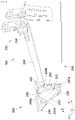
figure 1 déjà décrite, est une vue en perspective de l'arrière d'un mât d'aéronef avec des organes de fixation du mât à une aile d'aéronef, selon l'état de l'art, - la
figure 2 est une vue de côté d'un assemblage d'un mât avec une aile d'aéronef au moyen d'organes de fixation du mât à une aile comprenant un système arrière de fixation selon un mode de réalisation de l'invention, - la
figure 3 est une vue en perspective de la zone III de laFig. 2 montrant en détail le système arrière de fixation selon le mode de réalisation de l'invention, - la
figure 4 est une vue éclatée et en perspective du système arrière de fixation représenté à laFig. 3 , selon le mode de réalisation de l'invention.
- the
figure 1 already described, is a perspective view of the rear of an aircraft mast with members for attaching the mast to an aircraft wing, according to the state of the art, - the
picture 2 is a side view of an assembly of a mast with an aircraft wing by means of members for attaching the mast to a wing comprising a rear attachment system according to one embodiment of the invention, - the
picture 3 is a perspective view of Zone III of theFig. 2 showing in detail the rear fastening system according to the embodiment of the invention, - the
figure 4 is an exploded perspective view of the rear attachment system shown inFig. 3 , according to the embodiment of the invention.
En référence avec les
Dans la description, les termes relatifs à une position sont pris en référence par rapport à la flèche F représentant la direction d'avancement de l'aile /mât dans l'air sous l'effet de la poussée fournie par le turboréacteur.In the description, the terms relating to a position are taken in reference with respect to the arrow F representing the direction of advancement of the wing/mast in the air under the effect of the thrust supplied by the turbojet engine.
De manière connue, le mât 106 comprend une structure primaire 202 sous forme d'un caisson rigide qui s'étend d'avant en arrière en longueur selon un axe longitudinal X, parallèle à la direction d'avancement F de l'aéronef.In known manner, the
On appelle plan médian longitudinal V, le plan parallèle à l'axe longitudinal X, orthogonal au sol (c'est-à-dire à l'horizontale) et qui divise la structure primaire 202 en deux parties gauche et droite.Called longitudinal median plane V, the plane parallel to the longitudinal axis X, orthogonal to the ground (that is to say horizontally) and which divides the
La structure primaire 202 comprend un longeron supérieur 204 qui forme la face supérieure du caisson et qui est arrangé en regard de l'aile 104 sous laquelle est monté le mât 106. Une nervure 302 (visible en transparence à la
Les organes de fixation comprennent classiquement un système avant de fixation 250 du mât 106 à l'aile 104 arrangé sur la face supérieure de la structure primaire 202 globalement à mi-longueur de cette dernière, un système arrière de fixation 280 du mât 106 à l'aile 104 disposé à l'arrière de la structure primaire, et un système intermédiaire de fixation 256 du mât 106 à l'aile 104 disposé sur la face supérieure entre le système avant de fixation 250 et le système arrière de fixation 280.The fixing members conventionally comprise a
Dans le mode de réalisation illustré à la
Selon l'invention, le système arrière de fixation 280 comprend une paire de manilles verticales 282 montées articulées entre la face arrière de la structure primaire 202, et plus particulièrement une première ferrure 286, et un premier sabot 284 fixé à l'aile 104 et plus particulièrement ici au panneau d'intrados 216.According to the invention, the
La fixation de la paire de manilles verticales 282 à la structure primaire 202 est assurée ici par la première ferrure 286 qui est fixée à la structure primaire 202 au niveau de la nervure arrière 302, c'est-à-dire de la face arrière.The fixing of the pair of
Chaque manille de la paire de manilles verticales 282 peut être doublée.Each shackle of the pair of
Les manilles de la paire de manilles verticales 282 prennent en sandwich la première ferrure 286, d'une part, et le premier sabot 284, d'autre part. La fixation des manilles à la structure primaire 202 est assurée par une liaison de type chape avec un axe 287a-b orienté transversalement par rapport au mât 106 et traversant la paire de manille verticales 282 et la première ferrure 286 ou le premier sabot 284. Les manilles de la paire de manilles verticales 282 sont orientées quasiment verticalement.The shackles of the pair of
La fixation du premier sabot 284 au panneau d'intrados 216 est réalisée par exemple par soudure ou par mise en place d'éléments de visserie.The attachment of the
De la même manière, la fixation de la première ferrure 286 à la face arrière de la structure primaire 202 est réalisée par exemple par soudure ou par mise en place d'éléments de visserie.In the same way, the attachment of the
La paire de manilles verticales 282 permet une reprise des efforts principalement en Z.The pair of
Le système arrière de fixation 280 comporte également une paire de manilles transversales 288 montées articulées entre la face arrière de la structure primaire 202, et plus particulièrement une deuxième ferrure 290, et un deuxième sabot 292 fixé à l'aile 104 et plus particulièrement ici au panneau d'intrados 216.The
La fixation de la paire de manilles transversales 288 à la structure primaire 202 est assurée ici par la deuxième ferrure 290 qui est fixée à la structure primaire 202 au niveau de la nervure arrière 302, c'est-à-dire de la face arrière.The fixing of the pair of
Chaque manille de la paire de manilles transversales 288 peut être doublée.Each shackle of the pair of
Les manilles de la paire de manilles transversales 288 prennent en sandwich la deuxième ferrure 290, d'une part, et le deuxième sabot 292, d'autre part. La fixation des manilles à la structure primaire 202 est assurée par une liaison de type chape avec un axe 289a-b orienté longitudinalement et traversant la paire de manilles transversales 288 et la deuxième ferrure 290 ou le deuxième sabot 292. Les manilles de la paire de manilles transversales 288 sont orientées quasiment horizontalement et transversalement par rapport à la direction longitudinale X.The shackles of the pair of
La fixation du deuxième sabot 292 au panneau d'intrados 216 est réalisée par exemple par soudure ou par mise en place d'éléments de visserie.The attachment of the
De la même manière, la fixation de la deuxième ferrure 290 à la structure primaire 202 est réalisée par exemple par soudure ou par mise en place d'éléments de visserie.In the same way, the attachment of the second fitting 290 to the
La paire de manilles transversales 288 permet une reprise des efforts principalement en Y. En outre, la position de la paire de manilles transversales 288 au plus près de l'aile 104 permet de réduire l'introduction de moments secondaires dans l'assemblage.The pair of
Le mât 106 est alors au plus près de l'aile 104 du fait de la hauteur réduite à l'arrière du mât 106. En outre, la largeur du mât 106 à l'arrière est réduite par rapport à l'état de la technique, et l'inclinaison des panneaux latéraux du mât 106 est accentuée permettant une meilleure performance aérodynamique.The
Claims (3)
Applications Claiming Priority (1)
| Application Number | Priority Date | Filing Date | Title |
|---|---|---|---|
| FR2010077A FR3114801A1 (en) | 2020-10-02 | 2020-10-02 | ASSEMBLY OF A MAST WITH AN AIRCRAFT WING |
Publications (2)
| Publication Number | Publication Date |
|---|---|
| EP3978369A1 true EP3978369A1 (en) | 2022-04-06 |
| EP3978369B1 EP3978369B1 (en) | 2022-11-23 |
Family
ID=73793411
Family Applications (1)
| Application Number | Title | Priority Date | Filing Date |
|---|---|---|---|
| EP21197938.0A Active EP3978369B1 (en) | 2020-10-02 | 2021-09-21 | Assembly of a mast with an aircraft wing |
Country Status (4)
| Country | Link |
|---|---|
| US (1) | US11618579B2 (en) |
| EP (1) | EP3978369B1 (en) |
| CN (1) | CN114379790A (en) |
| FR (1) | FR3114801A1 (en) |
Families Citing this family (1)
| Publication number | Priority date | Publication date | Assignee | Title |
|---|---|---|---|---|
| FR3147253A1 (en) * | 2023-03-29 | 2024-10-04 | Airbus Operations (S.A.S.) | METHOD FOR INSTALLING A SYSTEM FOR FIXING A WING STRUCTURE TO A STRUCTURE OF AN AIRCRAFT MAST |
Citations (4)
| Publication number | Priority date | Publication date | Assignee | Title |
|---|---|---|---|---|
| US6095456A (en) * | 1996-12-23 | 2000-08-01 | The Boeing Company | Strut-wing interface having dual upper links |
| WO2007012667A1 (en) * | 2005-07-29 | 2007-02-01 | Airbus France | Assembly for aircraft comprising a wing system element as well as an attachment mast |
| FR2915178A1 (en) | 2007-04-23 | 2008-10-24 | Airbus France Sa | ATTACHMENT OF A MAT BOX ON A SAIL, PINCING A SIDE PANEL OF THE HOUSING |
| US20110127371A1 (en) * | 2009-12-01 | 2011-06-02 | Mitsubishi Aircraft Corporation | Engine mount of aircraft and aircraft |
Family Cites Families (9)
| Publication number | Priority date | Publication date | Assignee | Title |
|---|---|---|---|---|
| US5054715A (en) * | 1988-11-10 | 1991-10-08 | The Boeing Company | Apparatus and methods for reducing aircraft lifting surface flutter |
| FR2891252B1 (en) * | 2005-09-28 | 2007-10-26 | Airbus France Sas | MAT TO MONOLITHIC BODY |
| FR2914907B1 (en) * | 2007-04-16 | 2009-10-30 | Snecma Sa | SOFT SUSPENSION WITH COMB FOR TURBOMOTEUR |
| FR2920409B1 (en) * | 2007-08-27 | 2009-12-18 | Airbus France | BLOWER HOOD SUPPORT ROD MOUNTED ON THE HOOK AND ON THE AIR INTAKE OF THE NACELLE |
| FR2924094B1 (en) * | 2007-11-23 | 2010-01-15 | Snecma | TURBOREACTOR SUSPENDED ON AN AIRCRAFT PYLON |
| FR2934845A1 (en) * | 2008-08-11 | 2010-02-12 | Airbus France | ENGINE MAT FOR AN AIRCRAFT |
| FR3015434B1 (en) * | 2013-12-23 | 2017-12-08 | Snecma | TURBOMACHINE SUSPENSION |
| US9783313B2 (en) * | 2015-06-23 | 2017-10-10 | Rohr, Inc. | Installing or removing aircraft engines |
| FR3096351B1 (en) * | 2019-05-22 | 2021-06-11 | Airbus Operations Sas | REAR ENGINE ATTACHMENT SYSTEM FOR AN AIRCRAFT ENGINE CONTAINING A BEAM MADE IN THREE PARTS |
-
2020
- 2020-10-02 FR FR2010077A patent/FR3114801A1/en active Pending
-
2021
- 2021-09-21 EP EP21197938.0A patent/EP3978369B1/en active Active
- 2021-09-29 US US17/488,540 patent/US11618579B2/en active Active
- 2021-09-29 CN CN202111151813.7A patent/CN114379790A/en active Pending
Patent Citations (4)
| Publication number | Priority date | Publication date | Assignee | Title |
|---|---|---|---|---|
| US6095456A (en) * | 1996-12-23 | 2000-08-01 | The Boeing Company | Strut-wing interface having dual upper links |
| WO2007012667A1 (en) * | 2005-07-29 | 2007-02-01 | Airbus France | Assembly for aircraft comprising a wing system element as well as an attachment mast |
| FR2915178A1 (en) | 2007-04-23 | 2008-10-24 | Airbus France Sa | ATTACHMENT OF A MAT BOX ON A SAIL, PINCING A SIDE PANEL OF THE HOUSING |
| US20110127371A1 (en) * | 2009-12-01 | 2011-06-02 | Mitsubishi Aircraft Corporation | Engine mount of aircraft and aircraft |
Also Published As
| Publication number | Publication date |
|---|---|
| EP3978369B1 (en) | 2022-11-23 |
| US11618579B2 (en) | 2023-04-04 |
| US20220106048A1 (en) | 2022-04-07 |
| CN114379790A (en) | 2022-04-22 |
| FR3114801A1 (en) | 2022-04-08 |
Similar Documents
| Publication | Publication Date | Title |
|---|---|---|
| CA2613194C (en) | Engine mount for an aircraft, to be placed between an engine and an engine mounting structure | |
| EP2500268B1 (en) | Engine pylon for an aircraft | |
| EP2038175B1 (en) | Engine assembly for an aircraft comprising a support cradle for a fan shroud mounted on two separate elements | |
| EP2038176B1 (en) | Engine assembly for aircraft comprising an aerodynamic coupling fairing mounted on two separate elements | |
| EP2185413B1 (en) | Cradle for holding a fan coil mounted on the attachment pylon and on the nacelle air intake | |
| EP2139769B1 (en) | Fixation for pylon box on wings, clamping a side panel of the box | |
| EP1773660B1 (en) | Aircraft engine unit | |
| FR3068008B1 (en) | ENGINE ASSEMBLY FOR AN AIRCRAFT | |
| CA2575982C (en) | Engine assembly for aircraft | |
| FR2883256A1 (en) | ENGINE ATTACHMENT OF A MOUNTING SYSTEM INTERPOSED BETWEEN A COUPLING MACHINE AND AN AIRCRAFT ENGINE | |
| FR2891251A1 (en) | ENGINE ATTACHING MAT FOR AN AIRCRAFT | |
| FR2891244A1 (en) | ENGINE ATTACHING MAT FOR AN AIRCRAFT | |
| FR2887851A1 (en) | ENGINE ATTACHING MAT FOR AN AIRCRAFT | |
| FR2914908A1 (en) | APPARATUS FOR ATTACHING AN AIRCRAFT ENGINE AND AIRCRAFT HAVING AT LEAST ONE SUCH DEVICE. | |
| EP3670350B1 (en) | Propulsion assembly of an aircraft comprising a connecting fairing between a nacelle and a pylon of the aircraft provided with a removable cover and aircraft provided with said propulsion assembly | |
| EP3647202B1 (en) | Aircraft turbine engine assembly comprising a hinged cover | |
| EP3978369B1 (en) | Assembly of a mast with an aircraft wing | |
| FR3059298A1 (en) | AIRCRAFT ASSEMBLY COMPRISING A "OPEN ROTOR PULLER" TYPE ENGINE AND MEANS FOR HINGING IT WITH THE RIGID STRUCTURE OF A COUPLING MAT | |
| FR2887522A1 (en) | Aircraft shipset, has turboshaft engine fixing mast with units to fix box forming rigid structure under box forming aerofoil unit, where fixing units have fastener with insert fitting placed inside structure and box forming aerofoil unit | |
| EP3620388A1 (en) | Aircraft turbine engine assembly comprising a hinged cover | |
| FR3081837A1 (en) | AIRCRAFT TURBOMACHINE ASSEMBLY WITH ARTICULATED HOOD | |
| EP3945032A1 (en) | Assembly of a mast with an aircraft wing | |
| FR3096028A1 (en) | REAR ENGINE ATTACHMENT FOR AN AIRCRAFT ENGINE | |
| CA3032637A1 (en) | Aircraft portion with reduced wave resistance | |
| FR3121428A1 (en) | AIRCRAFT ENGINE MAST COMPRISING A MOVABLE SET OF COVERS |
Legal Events
| Date | Code | Title | Description |
|---|---|---|---|
| PUAI | Public reference made under article 153(3) epc to a published international application that has entered the european phase |
Free format text: ORIGINAL CODE: 0009012 |
|
| STAA | Information on the status of an ep patent application or granted ep patent |
Free format text: STATUS: REQUEST FOR EXAMINATION WAS MADE |
|
| 17P | Request for examination filed |
Effective date: 20210921 |
|
| AK | Designated contracting states |
Kind code of ref document: A1 Designated state(s): AL AT BE BG CH CY CZ DE DK EE ES FI FR GB GR HR HU IE IS IT LI LT LU LV MC MK MT NL NO PL PT RO RS SE SI SK SM TR |
|
| GRAP | Despatch of communication of intention to grant a patent |
Free format text: ORIGINAL CODE: EPIDOSNIGR1 |
|
| STAA | Information on the status of an ep patent application or granted ep patent |
Free format text: STATUS: GRANT OF PATENT IS INTENDED |
|
| INTG | Intention to grant announced |
Effective date: 20220726 |
|
| GRAS | Grant fee paid |
Free format text: ORIGINAL CODE: EPIDOSNIGR3 |
|
| GRAA | (expected) grant |
Free format text: ORIGINAL CODE: 0009210 |
|
| STAA | Information on the status of an ep patent application or granted ep patent |
Free format text: STATUS: THE PATENT HAS BEEN GRANTED |
|
| RBV | Designated contracting states (corrected) |
Designated state(s): AL AT BE BG CH CY CZ DE DK EE ES FI FR GB GR HR HU IE IS IT LI LT LU LV MC MK MT NL NO PL PT RO RS SE SI SK SM TR |
|
| AK | Designated contracting states |
Kind code of ref document: B1 Designated state(s): AL AT BE BG CH CY CZ DE DK EE ES FI FR GB GR HR HU IE IS IT LI LT LU LV MC MK MT NL NO PL PT RO RS SE SI SK SM TR |
|
| REG | Reference to a national code |
Ref country code: GB Ref legal event code: FG4D Free format text: NOT ENGLISH |
|
| REG | Reference to a national code |
Ref country code: CH Ref legal event code: EP |
|
| REG | Reference to a national code |
Ref country code: AT Ref legal event code: REF Ref document number: 1533008 Country of ref document: AT Kind code of ref document: T Effective date: 20221215 Ref country code: DE Ref legal event code: R096 Ref document number: 602021000828 Country of ref document: DE |
|
| REG | Reference to a national code |
Ref country code: IE Ref legal event code: FG4D Free format text: LANGUAGE OF EP DOCUMENT: FRENCH |
|
| REG | Reference to a national code |
Ref country code: LT Ref legal event code: MG9D |
|
| REG | Reference to a national code |
Ref country code: NL Ref legal event code: MP Effective date: 20221123 |
|
| REG | Reference to a national code |
Ref country code: AT Ref legal event code: MK05 Ref document number: 1533008 Country of ref document: AT Kind code of ref document: T Effective date: 20221123 |
|
| PG25 | Lapsed in a contracting state [announced via postgrant information from national office to epo] |
Ref country code: SE Free format text: LAPSE BECAUSE OF FAILURE TO SUBMIT A TRANSLATION OF THE DESCRIPTION OR TO PAY THE FEE WITHIN THE PRESCRIBED TIME-LIMIT Effective date: 20221123 Ref country code: PT Free format text: LAPSE BECAUSE OF FAILURE TO SUBMIT A TRANSLATION OF THE DESCRIPTION OR TO PAY THE FEE WITHIN THE PRESCRIBED TIME-LIMIT Effective date: 20230323 Ref country code: NO Free format text: LAPSE BECAUSE OF FAILURE TO SUBMIT A TRANSLATION OF THE DESCRIPTION OR TO PAY THE FEE WITHIN THE PRESCRIBED TIME-LIMIT Effective date: 20230223 Ref country code: LT Free format text: LAPSE BECAUSE OF FAILURE TO SUBMIT A TRANSLATION OF THE DESCRIPTION OR TO PAY THE FEE WITHIN THE PRESCRIBED TIME-LIMIT Effective date: 20221123 Ref country code: FI Free format text: LAPSE BECAUSE OF FAILURE TO SUBMIT A TRANSLATION OF THE DESCRIPTION OR TO PAY THE FEE WITHIN THE PRESCRIBED TIME-LIMIT Effective date: 20221123 Ref country code: ES Free format text: LAPSE BECAUSE OF FAILURE TO SUBMIT A TRANSLATION OF THE DESCRIPTION OR TO PAY THE FEE WITHIN THE PRESCRIBED TIME-LIMIT Effective date: 20221123 Ref country code: AT Free format text: LAPSE BECAUSE OF FAILURE TO SUBMIT A TRANSLATION OF THE DESCRIPTION OR TO PAY THE FEE WITHIN THE PRESCRIBED TIME-LIMIT Effective date: 20221123 |
|
| PG25 | Lapsed in a contracting state [announced via postgrant information from national office to epo] |
Ref country code: RS Free format text: LAPSE BECAUSE OF FAILURE TO SUBMIT A TRANSLATION OF THE DESCRIPTION OR TO PAY THE FEE WITHIN THE PRESCRIBED TIME-LIMIT Effective date: 20221123 Ref country code: PL Free format text: LAPSE BECAUSE OF FAILURE TO SUBMIT A TRANSLATION OF THE DESCRIPTION OR TO PAY THE FEE WITHIN THE PRESCRIBED TIME-LIMIT Effective date: 20221123 Ref country code: LV Free format text: LAPSE BECAUSE OF FAILURE TO SUBMIT A TRANSLATION OF THE DESCRIPTION OR TO PAY THE FEE WITHIN THE PRESCRIBED TIME-LIMIT Effective date: 20221123 Ref country code: IS Free format text: LAPSE BECAUSE OF FAILURE TO SUBMIT A TRANSLATION OF THE DESCRIPTION OR TO PAY THE FEE WITHIN THE PRESCRIBED TIME-LIMIT Effective date: 20230323 Ref country code: HR Free format text: LAPSE BECAUSE OF FAILURE TO SUBMIT A TRANSLATION OF THE DESCRIPTION OR TO PAY THE FEE WITHIN THE PRESCRIBED TIME-LIMIT Effective date: 20221123 Ref country code: GR Free format text: LAPSE BECAUSE OF FAILURE TO SUBMIT A TRANSLATION OF THE DESCRIPTION OR TO PAY THE FEE WITHIN THE PRESCRIBED TIME-LIMIT Effective date: 20230224 |
|
| PG25 | Lapsed in a contracting state [announced via postgrant information from national office to epo] |
Ref country code: NL Free format text: LAPSE BECAUSE OF FAILURE TO SUBMIT A TRANSLATION OF THE DESCRIPTION OR TO PAY THE FEE WITHIN THE PRESCRIBED TIME-LIMIT Effective date: 20221123 |
|
| PG25 | Lapsed in a contracting state [announced via postgrant information from national office to epo] |
Ref country code: SM Free format text: LAPSE BECAUSE OF FAILURE TO SUBMIT A TRANSLATION OF THE DESCRIPTION OR TO PAY THE FEE WITHIN THE PRESCRIBED TIME-LIMIT Effective date: 20221123 Ref country code: RO Free format text: LAPSE BECAUSE OF FAILURE TO SUBMIT A TRANSLATION OF THE DESCRIPTION OR TO PAY THE FEE WITHIN THE PRESCRIBED TIME-LIMIT Effective date: 20221123 Ref country code: EE Free format text: LAPSE BECAUSE OF FAILURE TO SUBMIT A TRANSLATION OF THE DESCRIPTION OR TO PAY THE FEE WITHIN THE PRESCRIBED TIME-LIMIT Effective date: 20221123 Ref country code: DK Free format text: LAPSE BECAUSE OF FAILURE TO SUBMIT A TRANSLATION OF THE DESCRIPTION OR TO PAY THE FEE WITHIN THE PRESCRIBED TIME-LIMIT Effective date: 20221123 Ref country code: CZ Free format text: LAPSE BECAUSE OF FAILURE TO SUBMIT A TRANSLATION OF THE DESCRIPTION OR TO PAY THE FEE WITHIN THE PRESCRIBED TIME-LIMIT Effective date: 20221123 |
|
| REG | Reference to a national code |
Ref country code: DE Ref legal event code: R097 Ref document number: 602021000828 Country of ref document: DE |
|
| PG25 | Lapsed in a contracting state [announced via postgrant information from national office to epo] |
Ref country code: SK Free format text: LAPSE BECAUSE OF FAILURE TO SUBMIT A TRANSLATION OF THE DESCRIPTION OR TO PAY THE FEE WITHIN THE PRESCRIBED TIME-LIMIT Effective date: 20221123 Ref country code: AL Free format text: LAPSE BECAUSE OF FAILURE TO SUBMIT A TRANSLATION OF THE DESCRIPTION OR TO PAY THE FEE WITHIN THE PRESCRIBED TIME-LIMIT Effective date: 20221123 |
|
| PLBE | No opposition filed within time limit |
Free format text: ORIGINAL CODE: 0009261 |
|
| STAA | Information on the status of an ep patent application or granted ep patent |
Free format text: STATUS: NO OPPOSITION FILED WITHIN TIME LIMIT |
|
| 26N | No opposition filed |
Effective date: 20230824 |
|
| REG | Reference to a national code |
Ref country code: DE Ref legal event code: R079 Ref document number: 602021000828 Country of ref document: DE Free format text: PREVIOUS MAIN CLASS: B64D0027260000 Ipc: B64D0027400000 |
|
| PG25 | Lapsed in a contracting state [announced via postgrant information from national office to epo] |
Ref country code: SI Free format text: LAPSE BECAUSE OF FAILURE TO SUBMIT A TRANSLATION OF THE DESCRIPTION OR TO PAY THE FEE WITHIN THE PRESCRIBED TIME-LIMIT Effective date: 20221123 |
|
| PGFP | Annual fee paid to national office [announced via postgrant information from national office to epo] |
Ref country code: FR Payment date: 20230928 Year of fee payment: 3 |
|
| PG25 | Lapsed in a contracting state [announced via postgrant information from national office to epo] |
Ref country code: LU Free format text: LAPSE BECAUSE OF NON-PAYMENT OF DUE FEES Effective date: 20230921 |
|
| REG | Reference to a national code |
Ref country code: BE Ref legal event code: MM Effective date: 20230930 |
|
| PG25 | Lapsed in a contracting state [announced via postgrant information from national office to epo] |
Ref country code: LU Free format text: LAPSE BECAUSE OF NON-PAYMENT OF DUE FEES Effective date: 20230921 Ref country code: IT Free format text: LAPSE BECAUSE OF FAILURE TO SUBMIT A TRANSLATION OF THE DESCRIPTION OR TO PAY THE FEE WITHIN THE PRESCRIBED TIME-LIMIT Effective date: 20221123 Ref country code: MC Free format text: LAPSE BECAUSE OF FAILURE TO SUBMIT A TRANSLATION OF THE DESCRIPTION OR TO PAY THE FEE WITHIN THE PRESCRIBED TIME-LIMIT Effective date: 20221123 |
|
| REG | Reference to a national code |
Ref country code: IE Ref legal event code: MM4A |
|
| PG25 | Lapsed in a contracting state [announced via postgrant information from national office to epo] |
Ref country code: IE Free format text: LAPSE BECAUSE OF NON-PAYMENT OF DUE FEES Effective date: 20230921 |
|
| PG25 | Lapsed in a contracting state [announced via postgrant information from national office to epo] |
Ref country code: IE Free format text: LAPSE BECAUSE OF NON-PAYMENT OF DUE FEES Effective date: 20230921 |
|
| PG25 | Lapsed in a contracting state [announced via postgrant information from national office to epo] |
Ref country code: BE Free format text: LAPSE BECAUSE OF NON-PAYMENT OF DUE FEES Effective date: 20230930 |
|
| PGFP | Annual fee paid to national office [announced via postgrant information from national office to epo] |
Ref country code: DE Payment date: 20240918 Year of fee payment: 4 |