EP3978309B1 - Arm cap friction hinge mechanism - Google Patents
Arm cap friction hinge mechanism Download PDFInfo
- Publication number
- EP3978309B1 EP3978309B1 EP21200641.5A EP21200641A EP3978309B1 EP 3978309 B1 EP3978309 B1 EP 3978309B1 EP 21200641 A EP21200641 A EP 21200641A EP 3978309 B1 EP3978309 B1 EP 3978309B1
- Authority
- EP
- European Patent Office
- Prior art keywords
- friction hinge
- link
- hinge
- coupled
- friction
- Prior art date
- Legal status (The legal status is an assumption and is not a legal conclusion. Google has not performed a legal analysis and makes no representation as to the accuracy of the status listed.)
- Active
Links
Images


Classifications
-
- B—PERFORMING OPERATIONS; TRANSPORTING
- B60—VEHICLES IN GENERAL
- B60N—SEATS SPECIALLY ADAPTED FOR VEHICLES; VEHICLE PASSENGER ACCOMMODATION NOT OTHERWISE PROVIDED FOR
- B60N2/00—Seats specially adapted for vehicles; Arrangement or mounting of seats in vehicles
- B60N2/75—Arm-rests
- B60N2/79—Adaptations for additional use of the arm-rests
- B60N2/793—Adaptations for additional use of the arm-rests for use as storage compartments
-
- B—PERFORMING OPERATIONS; TRANSPORTING
- B64—AIRCRAFT; AVIATION; COSMONAUTICS
- B64D—EQUIPMENT FOR FITTING IN OR TO AIRCRAFT; FLIGHT SUITS; PARACHUTES; ARRANGEMENT OR MOUNTING OF POWER PLANTS OR PROPULSION TRANSMISSIONS IN AIRCRAFT
- B64D11/00—Passenger or crew accommodation; Flight-deck installations not otherwise provided for
- B64D11/06—Arrangements of seats, or adaptations or details specially adapted for aircraft seats
- B64D11/0627—Seats combined with storage means
- B64D11/0636—Personal storage means or waste disposal bags
-
- E—FIXED CONSTRUCTIONS
- E05—LOCKS; KEYS; WINDOW OR DOOR FITTINGS; SAFES
- E05D—HINGES OR SUSPENSION DEVICES FOR DOORS, WINDOWS OR WINGS
- E05D11/00—Additional features or accessories of hinges
- E05D11/08—Friction devices between relatively-movable hinge parts
- E05D11/082—Friction devices between relatively-movable hinge parts with substantially radial friction, e.g. cylindrical friction surfaces
- E05D11/084—Friction devices between relatively-movable hinge parts with substantially radial friction, e.g. cylindrical friction surfaces the friction depending on direction of rotation or opening angle of the hinge
-
- E—FIXED CONSTRUCTIONS
- E05—LOCKS; KEYS; WINDOW OR DOOR FITTINGS; SAFES
- E05D—HINGES OR SUSPENSION DEVICES FOR DOORS, WINDOWS OR WINGS
- E05D3/00—Hinges with pins
- E05D3/06—Hinges with pins with two or more pins
-
- E—FIXED CONSTRUCTIONS
- E05—LOCKS; KEYS; WINDOW OR DOOR FITTINGS; SAFES
- E05Y—INDEXING SCHEME ASSOCIATED WITH SUBCLASSES E05D AND E05F, RELATING TO CONSTRUCTION ELEMENTS, ELECTRIC CONTROL, POWER SUPPLY, POWER SIGNAL OR TRANSMISSION, USER INTERFACES, MOUNTING OR COUPLING, DETAILS, ACCESSORIES, AUXILIARY OPERATIONS NOT OTHERWISE PROVIDED FOR, APPLICATION THEREOF
- E05Y2900/00—Application of doors, windows, wings or fittings thereof
- E05Y2900/50—Application of doors, windows, wings or fittings thereof for vehicles
- E05Y2900/53—Type of wing
- E05Y2900/538—Interior lids
Definitions
- Select aircraft seats may include a center console with an arm cap.
- the arm cap may provide access to a storage compartment within the center console.
- Consoles are disclosed in WO2017/180891 and JP S59 102637 .
- the adjacent aircraft seats may share a center console.
- the arm caps of each respective aircraft seat may interfere with one another when either is opened or closed.
- An arm cap friction hinge mechanism is provided as defined by claim 1.
- the actuation of the arm cap via the arm cap friction hinge mechanism may be configured to allow a cushion coupled to the arm cap to avoid an adjacent cushion of an adjacent arm cap during actuation.
- the upper hinge mount may be coupled to the first top link and the top friction hinge link opposite the center link.
- the upper pin mount may be coupled to the second top link and the top pin link opposite the center link.
- the at least one hinge mount may include a first hinge mount and a second hinge mount.
- the at least a second friction hinge may include a second friction hinge and a third friction hinge.
- the first hinge mount may be coupled to the center link via the second friction hinge.
- the second hinge mount may be coupled to the center link via the third friction hinge.
- portions of the center link, the first top link, the top friction hinge link, and the upper hinge mount may form a first linkage assembly.
- portions of the center link, the second top link, the top pin link, and the upper pin mount may form a second linkage assembly.
- the first friction hinge may be configured to act on the first linkage assembly and the second linkage assembly.
- the arm cap may be configured to actuate between the closed position and the first open position around the first friction hinge, the first linkage assembly, and the second linkage assembly.
- the at least a second friction hinge may provide a greater force on the center link than the force provided by the first friction hinge on the first linkage assembly and the second linkage assembly.
- the first friction hinge may be a one-way friction hinge.
- the at least a second friction hinge may be a two-way friction hinge.
- the arm cap friction hinge mechanism may include a first linkage assembly coupled to an arm cap of an aircraft seat.
- the arm cap friction hinge mechanism may include a second linkage assembly coupled to the arm cap of the aircraft seat.
- the arm cap friction hinge mechanism may include a center link.
- the center link may be a linkage of the first linkage assembly and a linkage of the second linkage assembly.
- the arm cap friction hinge mechanism may include a first friction hinge may be configured to act on the first linkage assembly and the second linkage assembly.
- the arm cap may be configured to actuate between a closed position and a first open position around the first friction hinge, the first linkage assembly, and the second linkage assembly.
- the arm cap friction hinge mechanism may include at least one hinge mount coupled to the aircraft seat.
- the arm cap friction hinge mechanism may include at least a second friction hinge.
- the center link may be coupled to the at least one hinge mount via the at least a second friction hinge.
- the arm cap may be configured to actuate between the first open position and a second open position about an axis through the at least a second friction hinge.
- the actuation of the arm cap around the first friction hinge, the first linkage assembly, the second linkage assembly, and the at least a second friction hinge may be configured to allow a cushion coupled to the arm cap to avoid an adjacent cushion of an adjacent arm cap during actuation.
- a letter following a reference numeral is intended to reference an embodiment of the feature or element that may be similar, but not necessarily identical, to a previously described element or feature bearing the same reference numeral (e.g., 1, 1a, 1b).
- reference numeral e.g. 1, 1a, 1b
- Such shorthand notations are used for purposes of convenience only and should not be construed to limit the disclosure in any way unless expressly stated to the contrary.
- any reference to “one embodiment” or “some embodiments” means that a particular element, feature, structure, or characteristic described in connection with the embodiment is included in at least one embodiment disclosed herein.
- the appearances of the phrase “in some embodiments” in various places in the specification are not necessarily all referring to the same embodiment, and embodiments may include one or more of the features expressly described or inherently present herein, or any combination of or sub-combination of two or more such features, along with any other features which may not necessarily be expressly described or inherently present in the instant disclosure.
- FIGS. 1A-3F in general illustrate an aircraft seat friction hinge mechanism, in accordance with one or more embodiments of the disclosure.
- FIGS. 1A-1C in general illustrate an aircraft seat assembly 100, in accordance with one or more embodiments of the disclosure.
- the aircraft seat assembly 100 may include one or more aircraft seats 102.
- Select aircraft seats 102 may include a center console 104 with an arm cap 106.
- the arm cap 106 may be directly coupled to the center console 104.
- the arm cap 106 may be coupled to a frame or chassis, and the frame or chassis may be coupled to the center console 104.
- the arm cap 106 may include a cushion 108.
- the arm cap 106 may provide access to a storage compartment 110 within the center console 104.
- adjacent aircraft seats 102 may share a center console 104, with respective arm caps 106 allowing access to respective storage compartment 110.
- the storage compartment 110 may be configured to receive and hold (e.g., contain, secure, or the like) one or more passenger amenities including, but not limited to, paper-printed materials (e.g., magazines, newspapers, pamphlets, or the like), handsets, select personal electronic devices (e.g., phones, tablets, phablets, laptops, music devices, digital video disc (DVD) players, handheld gaming consoles or devices, or the like), food products, drink products, or the like.
- the storage compartment 110 may include one or more electronic connections for one or more passenger amenities such as, but not limited to, one or more charging ports, one or more charging cables, or the like.
- the storage compartment 110 may include one or more electronic connections in communication with one or more components of the passenger compartment such as, but not limited to, one or more display device connection ports, one or more display device connection cables, one or more audio output jacks (e.g., headphone jacks), one or more audio input jacks, or the like.
- one or more display device connection ports such as, but not limited to, one or more display device connection ports, one or more display device connection cables, one or more audio output jacks (e.g., headphone jacks), one or more audio input jacks, or the like.
- the arm caps 106 of each respective aircraft seat 102 may interfere with one another when either is opened or closed.
- the cushions 108 of the arm caps 106 may interfere with one another during rotation of a first arm cap 106 while the second arm cap 106 remains stationary in a closed position.
- the interference may cause unnecessary wear in the cushions 108.
- the interference may provide a potentially-displeasing aesthetic to the aircraft seats 102.
- a solution such as increasing the gap between the cushions 108 could potentially provide similarly-displeasing aesthetic to the aircraft seats 102, and/or may require a re-design of other components of the aircraft seats 102 such that the arm caps 106 may not be swappable.
- the hinge mechanism should allow for adjacent arm caps 106 to open without interference.
- the mechanism should also able to the implemented within the adjacent arm caps 106 without increasing a gap between the adjacent arm caps 106.
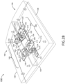
- FIGS. 2A and 2B in general illustrate a set of friction hinge mechanisms 200, in accordance with one or more embodiments of the disclosure. It is noted herein that “friction hinge mechanism,” “hinge mechanism,” “mechanism,” or similar terms may be equivalent, for purposes of the disclosure. In addition, it is noted herein each arm cap may include a friction hinge mechanism 200.
- a friction hinge mechanism 200 may include a center link 202.
- the center link 202 may be configured to receive one or more fasteners (e.g., pins, screws, or the like). It is noted herein the center link 202 and the one or more fasteners may be considered a center link assembly 204.
- the friction hinge mechanism 200 may include a set of top links 206.
- the friction hinge mechanism 200 may include two top links 206, with one on each side of the center link 202.
- Each of the set of top links 206 may be coupled to the center link 202 via one or more fasteners (e.g., pins, screws, or the like) received by (e.g., inserted into) the center link 202.
- the friction hinge mechanism 200 may include a top friction hinge link 208.
- the top friction hinge link 208 may be coupled to the center link 202 via one or more fasteners (e.g., pins, screws, or the like) received by (e.g., inserted into) the center link 202.
- the friction hinge mechanism 200 may include a top pin link 210.
- the top pin link 210 may be coupled to the center link 202 via one or more fasteners (e.g., pins, screws, or the like) received by (e.g., inserted into) the center link 202.
- top pin link 210 (and its corresponding top link 206) may be coupled to a different side of the center link 202 than the top friction hinge link 208 (and its corresponding top link 206).
- the friction hinge mechanism may be handed.
- the friction hinge mechanism 200 may include an upper hinge mount 212.
- the upper hinge mount 212 may be coupled to the top friction hinge link 208 via a friction hinge 214.
- the upper hinge mount 212 may be coupled to the top friction hinge link 208 opposite the center link 202 (e.g., opposite sides of the top friction hinge link 208).
- the upper hinge mount 218 may be coupled to the top friction hinge link 208 via one or more fasteners (e.g., pins, screws, or the like).
- the upper hinge mount 212 may be coupled to a top link 206 of the set of top links 206 via one or more fasteners (e.g., pins, screws, or the like).
- the upper hinge mount 212 may be coupled to the top link 206 opposite the center link 202 (e.g., opposite sides of the top link 206). It is noted herein the upper hinge mount 212, the friction hinge 214, and the one or more fasteners may be considered a hinge mount assembly 216. It is noted herein, however, the upper hinge mount 218 may be coupled to the top link 206 via a friction hinge.
- the friction hinge mechanism 200 may include an upper pin mount 218.
- the upper pin mount 218 may be coupled to a top link 206 of the set of top links 206 via one or more fasteners (e.g., pins, screws, or the like).
- the upper pin mount 218 may be coupled to the top link 206 opposite the center link 202 (e.g., opposite sides of the top link 206).
- the upper pin mount 218 may be coupled to the top pin link 210 via one or more fasteners (e.g., pins, screws, or the like).
- the upper pin mount 218 may be coupled to the top pin link 210 opposite the center link 202 (e.g., opposite sides of the top pin link 210).
- the upper pin mount 218 and the one or more fasteners may be considered a pin mount assembly 220. It is noted herein, however, the upper pin mount 218 may be coupled to the top link 206 and/or the top pin link 210 via a friction hinge.
- the friction hinge mechanism 200 may be coupled to a set of hinge mounts 222.
- the center link 202 may be coupled to a hinge mount 222 of the set of hinge mounts 222 via a friction hinge 224.
- the center link 202 may be coupled to each of the set of hinge mounts 222 via a friction hinge 224.
- the center link 202 may be coupled to a second hinge mount 222 of the set of hinge mounts 222 via one or more fasteners (e.g., pins, screws, or the like).
- the center link 202 may be coupled to a first hinge mount 222 of the set of hinge mounts 222 via a friction hinge 224, and a second hinge mount 222 of the set of hinge mounts 222 via one or more fasteners.
- each hinge mount 222 of the set of hinge mounts 222 may be a double hinge mount 222.
- embodiments of the disclosure illustrate a set of friction hinge mechanisms 200 being used with adjacent arm caps 106, however, it is noted herein the friction hinge mechanism 200 may be used with a standalone or singular arm cap 106 (e.g., where the aircraft seat 102 is standalone or singular).
- each hinge mount 222 of the set of hinge mounts 222 may be a single hinge mount 222. Therefore, the above description should not be interpreted as a limitation on the present disclosure but merely an illustration.
- FIGS. 3A-3F in general illustrate an operation of the friction hinge mechanism 200, in accordance with one or more embodiments of the disclosure.
- FIGS. 3A-3F illustrate parts of friction hinge mechanisms 200 from adjacent arm caps 106, it should be understood from FIGS. 2A and 2B that the friction hinge mechanisms 200 are handed such that each friction hinge mechanism 200 includes both parts as illustrated in FIGS. 3A-3F in the adjacent arm caps 106.
- the friction hinge mechanism 200 may include a linkage assembly 300.
- the linkage assembly 300 may be a four-bar linkage assembly.
- the linkage assembly 300 may be defined by at least a portion of the center link 202, a top link 206, a top friction hinge link 208, and at least a portion of an upper hinge mount 212.
- the friction hinge mechanism 200 may include a linkage assembly 302.
- the linkage assembly 302 may be a four-bar linkage assembly.
- the linkage assembly 302 may be defined by at least a portion of the center link 202, a top link 206, a top pin link 210, and at least a portion of an upper pin mount 218.
- a friction hinge 214 may act on the linkage assembly 300 (e.g., directly) and the linkage assembly 302 (e.g., indirectly, through the center link 202) as the arm cap actuates between a closed position (e.g., as illustrated in FIG. 3A ) and a first open position (e.g., as illustrated in FIG. 3D ).
- the actuation between the closed position and the first open position may pass through any number of intermediate positions (e.g., example intermediate positions being illustrated in FIGS. 3B and 3C ).
- the linkage assemblies 300, 302 may at least partially collapse inward.
- the arm cap 106 actuates not about a single fixed point, but instead actuates about a point that shifts with the at least partial collapsing of the linkage assemblies 300, 302. It is noted herein, however, the linkage assemblies 300, 302 may include linkages that are configured to allow the arm cap 106 to actuate about a single fixed point. Therefore, the above description should not be interpreted as a limitation on the present disclosure but merely an illustration.
- the friction hinge mechanism 200 may include a linkage assembly 304.
- the linkage assembly 304 may include, but is not limited to, the center link 202.
- the friction hinge mechanism 200 may include a linkage assembly 306.
- the linkage assembly 304 may include, but is not limited to, the center link 202.
- a friction hinge 224 may act on the linkage assembly 304 (e.g., directly) and the linkage assembly 308 (e.g., indirectly, through the center link 202) as the arm cap actuates between the first open position (e.g., as illustrated in FIG. 3D ) and a second open position (e.g., as illustrated in FIG. 3F ).
- the actuation between the first open position and the second open position may pass through any number of intermediate positions (e.g., an example intermediate position being illustrated in FIG. 3E ).
- the first open position may be considered a partially-open position and the second open position may be considered a fully-open position.
- the linkage assemblies 304, 306 may rotate or pivot about an axis through the friction hinge 224. Due to the increased space or gap generated between the adjacent arm caps 106 during the actuation between the closed position and the first open position, the arm cap 106 is allowed to actuate between the first open position and the second open position without interfering with the adjacent arm cap 106 (e.g., interference caused by the cushions 108 coming into contact). However, the increased space or gap is only generated during the actuation, and is not present when the arm cap 106 is in the closed position or in the fully open position.
- the friction hinge 224 may provide a greater force on the linkage assemblies 304, 306 (e.g., the center link 202) than the friction hinge 214 provides on the linkage assemblies 300, 302, such that the actuation between the closed position and the first open position is fully completed before the actuation between the first open position and the second open position occurs.
- the friction hinge 214 and/or the friction hinge 224 may be configured to hold the arm cap 106 at select positions absent an applied force.
- the friction hinge 224 may be a one-way friction hinge 224, which keeps the linkage assemblies 304, 306 from actuating absent an applied force until the completion of the transition between the closed position and the first open position.
- the one-way nature of the friction hinge 224 may allow the linkage assemblies 304, 306 to actuate prior to the actuation of the linkages 300, 302 between the second open position and the closed position.
- the friction hinge 214 may be a two-way friction hinge 214, which prevents the linkage assemblies 300, 302 from actuating in any direction absent an applied force. It is noted herein, however, the friction hinge 214 may be a one-way friction hinge 214, which may prevent the linkage assemblies 300, 302 from actuating between the closed position and the first open position absent an applied force, but may allow for the linkage assemblies 300, 302 to actuate between the first open position and the closed position without any applied force.
- the friction hinge mechanism 200 may be considered a two-part mechanism, where the first part of the mechanism is the actuation between the closed position and the first open position, and the second part of the mechanism is the actuation between the first open position and the second open position. It is noted herein the friction hinge 224 may hold the arm cap 106 in the second open position, absent an applied force.
- linkage assemblies 300, 302 and the linkage assemblies 304, 306 may simultaneously actuate, to the extent there is no interference by the arm cap 106 with the adjacent arm cap 106 (e.g., interference caused by the cushions 108 coming into contact).
- an arm cap 106 may be configured to rotate from the closed position to a fully-open position without breaching a plane 308 (e.g., as defined by a surface of an adjacent arm cap 306), where the breaching the plane 308 would cause interference between the arm caps 106 (e.g., by allowing the cushions 108 to come into contact with each other).
- actuation about the linkage assemblies 300, 302, and then the second actuation about the linkage assemblies 304, 306 allow for actuation of the adjacent arm caps 106 without a need for an increased gap between the adjacent arm caps 106.
- the arm cap 106 is allowed to actuate between the closed position and the first open position without interfering with (e.g., avoiding) the adjacent arm cap 106 (e.g., interference caused by the cushions 108 coming into contact). It is noted herein the friction hinge 214 may hold the arm cap 106 in the first open position, absent an applied force.
- the arm cap 106 may actuate between the second open position and the closed position via one or more of the actuations illustrated in FIGS. 3A-3F being performed in a different (e.g., reverse) order.
- friction hinges 214, 224 it is noted herein the various components of the friction hinge mechanism 200 may be configured with physical limiters (e.g., mechanical detents, or the like) that provide additional force to hold the arm cap 106 in select positions and/or prevent out-of-turn actuation, similar to the operation of the friction hinges 214, 224. Therefore, the above description should not be interpreted as a limitation on the present disclosure but merely an illustration.
- physical limiters e.g., mechanical detents, or the like
- friction hinge mechanism 200 may need to be configured in accordance with aviation guidelines and/or standards set forth by, but not limited to, the Federal Aviation Administration (FAA), the European Aviation Safety Agency (EASA) or any other flight certification agency or organization; the American National Standards Institute (ANSI), Aeronautical Radio, Incorporated (ARINC), SAE International, or any other standards setting organization or company; the Radio Technical Commission for Aeronautics (RTCA) or any other guidelines agency or organization; or the like.
- FAA Federal Aviation Administration
- EASA European Aviation Safety Agency
- ARINC Aeronautical Radio, Incorporated
- SAE International or any other standards setting organization or company
- RTCA Radio Technical Commission for Aeronautics
- the friction hinge mechanism 200 and/or components of the friction hinge mechanism 200 are not limited to the aviation environment and/or the aircraft components within the aviation environment.
- the friction hinge mechanism 200 and/or components of the friction hinge mechanism 200 may be configured for any type of vehicle known in the art.
- the vehicle may be any air, space, land, or water-based personal equipment or vehicle; any air, space, land, or water-based commercial equipment or vehicle; any air, space, land, or water-based military equipment or vehicle known in the art.
- the friction hinge mechanism 200 and/or components of the friction hinge mechanism 200 may be configured for commercial or industrial use in either a home or a business. Therefore, the above description should not be interpreted as a limitation on the present invention but merely an illustration.
Landscapes
- Engineering & Computer Science (AREA)
- Mechanical Engineering (AREA)
- Aviation & Aerospace Engineering (AREA)
- Transportation (AREA)
- Pivots And Pivotal Connections (AREA)
Description
- Select aircraft seats may include a center console with an arm cap. The arm cap may provide access to a storage compartment within the center console. Consoles are disclosed in
WO2017/180891 andJP S59 102637 - An arm cap friction hinge mechanism is provided as defined by claim 1.
- In some embodiments, the actuation of the arm cap via the arm cap friction hinge mechanism may be configured to allow a cushion coupled to the arm cap to avoid an adjacent cushion of an adjacent arm cap during actuation.
- In some embodiments, the first top link and the top friction hinge link may be coupled to a first side of the center link. The second top link and the top pin link may be coupled to a second side of the center link.
- In some embodiments, the upper hinge mount may be coupled to the first top link and the top friction hinge link opposite the center link.
- In some embodiments, the upper pin mount may be coupled to the second top link and the top pin link opposite the center link.
- In some embodiments, the at least one hinge mount may include a first hinge mount and a second hinge mount.
- In some embodiments, the at least a second friction hinge may include a second friction hinge and a third friction hinge. The first hinge mount may be coupled to the center link via the second friction hinge. The second hinge mount may be coupled to the center link via the third friction hinge.
- In some embodiments, portions of the center link, the first top link, the top friction hinge link, and the upper hinge mount may form a first linkage assembly.
- In some embodiments, portions of the center link, the second top link, the top pin link, and the upper pin mount may form a second linkage assembly.
- In some embodiments, the first friction hinge may be configured to act on the first linkage assembly and the second linkage assembly. The arm cap may be configured to actuate between the closed position and the first open position around the first friction hinge, the first linkage assembly, and the second linkage assembly.
- In some embodiments, the at least a second friction hinge may provide a greater force on the center link than the force provided by the first friction hinge on the first linkage assembly and the second linkage assembly.
- In some embodiments, the first friction hinge may be a one-way friction hinge.
- In some embodiments, the at least a second friction hinge may be a two-way friction hinge.
- An arm cap friction hinge mechanism is also described. The arm cap friction hinge mechanism may include a first linkage assembly coupled to an arm cap of an aircraft seat. The arm cap friction hinge mechanism may include a second linkage assembly coupled to the arm cap of the aircraft seat. The arm cap friction hinge mechanism may include a center link. The center link may be a linkage of the first linkage assembly and a linkage of the second linkage assembly. The arm cap friction hinge mechanism may include a first friction hinge may be configured to act on the first linkage assembly and the second linkage assembly. The arm cap may be configured to actuate between a closed position and a first open position around the first friction hinge, the first linkage assembly, and the second linkage assembly. The arm cap friction hinge mechanism may include at least one hinge mount coupled to the aircraft seat. The arm cap friction hinge mechanism may include at least a second friction hinge. The center link may be coupled to the at least one hinge mount via the at least a second friction hinge. The arm cap may be configured to actuate between the first open position and a second open position about an axis through the at least a second friction hinge.
- In some embodiments, the actuation of the arm cap around the first friction hinge, the first linkage assembly, the second linkage assembly, and the at least a second friction hinge may be configured to allow a cushion coupled to the arm cap to avoid an adjacent cushion of an adjacent arm cap during actuation.
- This Summary is provided solely as an introduction to subject matter that is fully described in the Detailed Description and Drawings. The Summary should not be considered to describe essential features nor be used to determine the scope of the Claims. Moreover, it is to be understood that both the foregoing Summary and the following Detailed Description are examples and explanatory only and are not necessarily restrictive of the subject matter claimed.
- The detailed description is described with reference to the accompanying figures. The use of the same reference numbers in different instances in the description and the figures may indicate similar or identical items. Various embodiments or examples ("examples") of the present disclosure are disclosed in the following detailed description and the accompanying drawings. The drawings are not necessarily to scale. In general, operations of disclosed processes may be performed in an arbitrary order, unless otherwise provided in the claims. In the drawings:
-
FIG. 1A illustrates a perspective view of a set of aircraft seats, in accordance with one or more embodiments of the disclosure; -
FIG. 1B illustrates a perspective view of a portion of a set of aircraft seats, in accordance with one or more embodiments of the disclosure; -
FIG. 1C illustrates a perspective view of a portion of a set of aircraft seats, in accordance with one or more embodiments of the disclosure; -
FIG. 2A illustrates a perspective view of a set of arm cap friction hinge mechanisms, in accordance with one or more embodiments of the disclosure; -
FIG. 2B illustrates a perspective view of a set of arm cap friction hinge mechanisms, in accordance with one or more embodiments of the disclosure; -
FIG. 3A illustrates a cross-section elevation view of a set of arm cap friction hinge mechanisms, in accordance with one or more embodiments of the disclosure; -
FIG. 3B illustrates a cross-section elevation view of a set of arm cap friction hinge mechanisms, in accordance with one or more embodiments of the disclosure; -
FIG. 3C illustrates a cross-section elevation view of a set of arm cap friction hinge mechanisms, in accordance with one or more embodiments of the disclosure; -
FIG. 3D illustrates a cross-section elevation view of a set of arm cap friction hinge mechanisms, in accordance with one or more embodiments of the disclosure; -
FIG. 3E illustrates a cross-section elevation view of a set of arm cap friction hinge mechanisms, in accordance with one or more embodiments of the disclosure; and -
FIG. 3F illustrates a cross-section elevation view of a set of arm cap friction hinge mechanisms, in accordance with one or more embodiments of the disclosure. - Reference will now be made in detail to the subject matter disclosed, which is illustrated in the accompanying drawings.
- Before explaining one or more embodiments of the disclosure in detail, it is to be understood the embodiments are not limited in their application to the details of construction and the arrangement of the components or steps or methodologies set forth in the following description or illustrated in the drawings. In the following detailed description of embodiments, numerous specific details may be set forth in order to provide a more thorough understanding of the disclosure. However, it will be apparent to one of ordinary skill in the art having the benefit of the instant disclosure the embodiments disclosed herein may be practiced without some of these specific details. In other instances, well-known features may not be described in detail to avoid unnecessarily complicating the instant disclosure.
- As used herein a letter following a reference numeral is intended to reference an embodiment of the feature or element that may be similar, but not necessarily identical, to a previously described element or feature bearing the same reference numeral (e.g., 1, 1a, 1b). Such shorthand notations are used for purposes of convenience only and should not be construed to limit the disclosure in any way unless expressly stated to the contrary.
- Further, unless expressly stated to the contrary, "or" refers to an inclusive or and not to an exclusive or. For example, a condition A or B is satisfied by anyone of the following: A is true (or present) and B is false (or not present), A is false (or not present) and B is true (or present), and both A and B are true (or present).
- In addition, use of "a" or "an" may be employed to describe elements and components of embodiments disclosed herein. This is done merely for convenience and "a" and "an" are intended to include "one," "one or more," or "at least one," and the singular also includes the plural unless it is obvious that it is meant otherwise.
- Finally, as used herein any reference to "one embodiment" or "some embodiments" means that a particular element, feature, structure, or characteristic described in connection with the embodiment is included in at least one embodiment disclosed herein. The appearances of the phrase "in some embodiments" in various places in the specification are not necessarily all referring to the same embodiment, and embodiments may include one or more of the features expressly described or inherently present herein, or any combination of or sub-combination of two or more such features, along with any other features which may not necessarily be expressly described or inherently present in the instant disclosure.
-
FIGS. 1A-3F in general illustrate an aircraft seat friction hinge mechanism, in accordance with one or more embodiments of the disclosure. -
FIGS. 1A-1C in general illustrate anaircraft seat assembly 100, in accordance with one or more embodiments of the disclosure. Theaircraft seat assembly 100 may include one or more aircraft seats 102. - Select aircraft seats 102 (e.g., such as business-class seats) may include a
center console 104 with anarm cap 106. For example, thearm cap 106 may be directly coupled to thecenter console 104. By way of another example, thearm cap 106 may be coupled to a frame or chassis, and the frame or chassis may be coupled to thecenter console 104. Thearm cap 106 may include acushion 108. Thearm cap 106 may provide access to astorage compartment 110 within thecenter console 104. In select arrangements,adjacent aircraft seats 102 may share acenter console 104, with respective arm caps 106 allowing access torespective storage compartment 110. - The
storage compartment 110 may be configured to receive and hold (e.g., contain, secure, or the like) one or more passenger amenities including, but not limited to, paper-printed materials (e.g., magazines, newspapers, pamphlets, or the like), handsets, select personal electronic devices (e.g., phones, tablets, phablets, laptops, music devices, digital video disc (DVD) players, handheld gaming consoles or devices, or the like), food products, drink products, or the like. Thestorage compartment 110 may include one or more electronic connections for one or more passenger amenities such as, but not limited to, one or more charging ports, one or more charging cables, or the like. Thestorage compartment 110 may include one or more electronic connections in communication with one or more components of the passenger compartment such as, but not limited to, one or more display device connection ports, one or more display device connection cables, one or more audio output jacks (e.g., headphone jacks), one or more audio input jacks, or the like. - In these arrangements, the arm caps 106 of each
respective aircraft seat 102 may interfere with one another when either is opened or closed. For example, thecushions 108 of the arm caps 106 may interfere with one another during rotation of afirst arm cap 106 while thesecond arm cap 106 remains stationary in a closed position. The interference may cause unnecessary wear in thecushions 108. In addition, the interference may provide a potentially-displeasing aesthetic to the aircraft seats 102. However, a solution such as increasing the gap between thecushions 108 could potentially provide similarly-displeasing aesthetic to the aircraft seats 102, and/or may require a re-design of other components of the aircraft seats 102 such that the arm caps 106 may not be swappable. - Therefore, it would be beneficial to provide aircraft seat arm caps with an improved hinge mechanism. The hinge mechanism should allow for adjacent arm caps 106 to open without interference. The mechanism should also able to the implemented within the adjacent arm caps 106 without increasing a gap between the adjacent arm caps 106.
-
FIGS. 2A and2B in general illustrate a set offriction hinge mechanisms 200, in accordance with one or more embodiments of the disclosure. It is noted herein that "friction hinge mechanism," "hinge mechanism," "mechanism," or similar terms may be equivalent, for purposes of the disclosure. In addition, it is noted herein each arm cap may include afriction hinge mechanism 200. - A
friction hinge mechanism 200 may include acenter link 202. Thecenter link 202 may be configured to receive one or more fasteners (e.g., pins, screws, or the like). It is noted herein thecenter link 202 and the one or more fasteners may be considered acenter link assembly 204. - The
friction hinge mechanism 200 may include a set oftop links 206. For example, thefriction hinge mechanism 200 may include twotop links 206, with one on each side of thecenter link 202. Each of the set oftop links 206 may be coupled to thecenter link 202 via one or more fasteners (e.g., pins, screws, or the like) received by (e.g., inserted into) thecenter link 202. - The
friction hinge mechanism 200 may include a topfriction hinge link 208. The topfriction hinge link 208 may be coupled to thecenter link 202 via one or more fasteners (e.g., pins, screws, or the like) received by (e.g., inserted into) thecenter link 202. Thefriction hinge mechanism 200 may include atop pin link 210. Thetop pin link 210 may be coupled to thecenter link 202 via one or more fasteners (e.g., pins, screws, or the like) received by (e.g., inserted into) thecenter link 202. It is noted herein the top pin link 210 (and its corresponding top link 206) may be coupled to a different side of thecenter link 202 than the top friction hinge link 208 (and its corresponding top link 206). In this regard, the friction hinge mechanism may be handed. - The
friction hinge mechanism 200 may include anupper hinge mount 212. Theupper hinge mount 212 may be coupled to the topfriction hinge link 208 via afriction hinge 214. For example, theupper hinge mount 212 may be coupled to the topfriction hinge link 208 opposite the center link 202 (e.g., opposite sides of the top friction hinge link 208). It is noted herein, however, theupper hinge mount 218 may be coupled to the topfriction hinge link 208 via one or more fasteners (e.g., pins, screws, or the like). Theupper hinge mount 212 may be coupled to atop link 206 of the set oftop links 206 via one or more fasteners (e.g., pins, screws, or the like). For example, theupper hinge mount 212 may be coupled to thetop link 206 opposite the center link 202 (e.g., opposite sides of the top link 206). It is noted herein theupper hinge mount 212, thefriction hinge 214, and the one or more fasteners may be considered ahinge mount assembly 216. It is noted herein, however, theupper hinge mount 218 may be coupled to thetop link 206 via a friction hinge. - The
friction hinge mechanism 200 may include anupper pin mount 218. Theupper pin mount 218 may be coupled to atop link 206 of the set oftop links 206 via one or more fasteners (e.g., pins, screws, or the like). For example, theupper pin mount 218 may be coupled to thetop link 206 opposite the center link 202 (e.g., opposite sides of the top link 206). Theupper pin mount 218 may be coupled to thetop pin link 210 via one or more fasteners (e.g., pins, screws, or the like). For example, theupper pin mount 218 may be coupled to thetop pin link 210 opposite the center link 202 (e.g., opposite sides of the top pin link 210). It is noted herein theupper pin mount 218 and the one or more fasteners may be considered apin mount assembly 220. It is noted herein, however, theupper pin mount 218 may be coupled to thetop link 206 and/or thetop pin link 210 via a friction hinge. - The
friction hinge mechanism 200 may be coupled to a set of hinge mounts 222. For example, thecenter link 202 may be coupled to ahinge mount 222 of the set of hinge mounts 222 via afriction hinge 224. For instance, thecenter link 202 may be coupled to each of the set of hinge mounts 222 via afriction hinge 224. By way of another example, thecenter link 202 may be coupled to asecond hinge mount 222 of the set of hinge mounts 222 via one or more fasteners (e.g., pins, screws, or the like). For instance, thecenter link 202 may be coupled to afirst hinge mount 222 of the set of hinge mounts 222 via afriction hinge 224, and asecond hinge mount 222 of the set of hinge mounts 222 via one or more fasteners. - Where the
friction hinge mechanism 200 is installed in each of a set of adjacent arm caps 106, it is noted herein eachhinge mount 222 of the set of hinge mounts 222 may be adouble hinge mount 222. Although embodiments of the disclosure illustrate a set offriction hinge mechanisms 200 being used with adjacent arm caps 106, however, it is noted herein thefriction hinge mechanism 200 may be used with a standalone or singular arm cap 106 (e.g., where theaircraft seat 102 is standalone or singular). Here, eachhinge mount 222 of the set of hinge mounts 222 may be asingle hinge mount 222. Therefore, the above description should not be interpreted as a limitation on the present disclosure but merely an illustration. -
FIGS. 3A-3F in general illustrate an operation of thefriction hinge mechanism 200, in accordance with one or more embodiments of the disclosure. AlthoughFIGS. 3A-3F illustrate parts offriction hinge mechanisms 200 from adjacent arm caps 106, it should be understood fromFIGS. 2A and2B that thefriction hinge mechanisms 200 are handed such that eachfriction hinge mechanism 200 includes both parts as illustrated inFIGS. 3A-3F in the adjacent arm caps 106. - The
friction hinge mechanism 200 may include alinkage assembly 300. For example, thelinkage assembly 300 may be a four-bar linkage assembly. For instance, thelinkage assembly 300 may be defined by at least a portion of thecenter link 202, atop link 206, a topfriction hinge link 208, and at least a portion of anupper hinge mount 212. - The
friction hinge mechanism 200 may include alinkage assembly 302. For example, thelinkage assembly 302 may be a four-bar linkage assembly. For instance, thelinkage assembly 302 may be defined by at least a portion of thecenter link 202, atop link 206, atop pin link 210, and at least a portion of anupper pin mount 218. - A
friction hinge 214 may act on the linkage assembly 300 (e.g., directly) and the linkage assembly 302 (e.g., indirectly, through the center link 202) as the arm cap actuates between a closed position (e.g., as illustrated inFIG. 3A ) and a first open position (e.g., as illustrated inFIG. 3D ). The actuation between the closed position and the first open position may pass through any number of intermediate positions (e.g., example intermediate positions being illustrated inFIGS. 3B and3C ). During the actuation, thelinkage assemblies linkage assemblies arm cap 106 actuates not about a single fixed point, but instead actuates about a point that shifts with the at least partial collapsing of thelinkage assemblies linkage assemblies arm cap 106 to actuate about a single fixed point. Therefore, the above description should not be interpreted as a limitation on the present disclosure but merely an illustration. - The
friction hinge mechanism 200 may include alinkage assembly 304. For example, thelinkage assembly 304 may include, but is not limited to, thecenter link 202. - The
friction hinge mechanism 200 may include alinkage assembly 306. For example, thelinkage assembly 304 may include, but is not limited to, thecenter link 202. - A
friction hinge 224 may act on the linkage assembly 304 (e.g., directly) and the linkage assembly 308 (e.g., indirectly, through the center link 202) as the arm cap actuates between the first open position (e.g., as illustrated inFIG. 3D ) and a second open position (e.g., as illustrated inFIG. 3F ). The actuation between the first open position and the second open position may pass through any number of intermediate positions (e.g., an example intermediate position being illustrated inFIG. 3E ). For purposes of the disclosure, the first open position may be considered a partially-open position and the second open position may be considered a fully-open position. - During the actuation, the
linkage assemblies friction hinge 224. Due to the increased space or gap generated between the adjacent arm caps 106 during the actuation between the closed position and the first open position, thearm cap 106 is allowed to actuate between the first open position and the second open position without interfering with the adjacent arm cap 106 (e.g., interference caused by thecushions 108 coming into contact). However, the increased space or gap is only generated during the actuation, and is not present when thearm cap 106 is in the closed position or in the fully open position. - The
friction hinge 224 may provide a greater force on thelinkage assemblies 304, 306 (e.g., the center link 202) than thefriction hinge 214 provides on thelinkage assemblies - The
friction hinge 214 and/or thefriction hinge 224 may be configured to hold thearm cap 106 at select positions absent an applied force. - The
friction hinge 224 may be a one-way friction hinge 224, which keeps thelinkage assemblies friction hinge 224, however, may allow thelinkage assemblies linkages - The
friction hinge 214 may be a two-way friction hinge 214, which prevents thelinkage assemblies friction hinge 214 may be a one-way friction hinge 214, which may prevent thelinkage assemblies linkage assemblies - In this regard, the
friction hinge mechanism 200 may be considered a two-part mechanism, where the first part of the mechanism is the actuation between the closed position and the first open position, and the second part of the mechanism is the actuation between the first open position and the second open position. It is noted herein thefriction hinge 224 may hold thearm cap 106 in the second open position, absent an applied force. - It is noted herein, however, that it is contemplated the
linkage assemblies linkage assemblies arm cap 106 with the adjacent arm cap 106 (e.g., interference caused by thecushions 108 coming into contact). - As such, an
arm cap 106 may be configured to rotate from the closed position to a fully-open position without breaching a plane 308 (e.g., as defined by a surface of an adjacent arm cap 306), where the breaching theplane 308 would cause interference between the arm caps 106 (e.g., by allowing thecushions 108 to come into contact with each other). In addition, the actuation about thelinkage assemblies linkage assemblies - In this regard, the
arm cap 106 is allowed to actuate between the closed position and the first open position without interfering with (e.g., avoiding) the adjacent arm cap 106 (e.g., interference caused by thecushions 108 coming into contact). It is noted herein thefriction hinge 214 may hold thearm cap 106 in the first open position, absent an applied force. - Although not shown, it should be understood the
arm cap 106 may actuate between the second open position and the closed position via one or more of the actuations illustrated inFIGS. 3A-3F being performed in a different (e.g., reverse) order. - Although embodiments of the present disclosure describe friction hinges 214, 224, it is noted herein the various components of the
friction hinge mechanism 200 may be configured with physical limiters (e.g., mechanical detents, or the like) that provide additional force to hold thearm cap 106 in select positions and/or prevent out-of-turn actuation, similar to the operation of the friction hinges 214, 224. Therefore, the above description should not be interpreted as a limitation on the present disclosure but merely an illustration. - It is noted herein the
friction hinge mechanism 200 may need to be configured in accordance with aviation guidelines and/or standards set forth by, but not limited to, the Federal Aviation Administration (FAA), the European Aviation Safety Agency (EASA) or any other flight certification agency or organization; the American National Standards Institute (ANSI), Aeronautical Radio, Incorporated (ARINC), SAE International, or any other standards setting organization or company; the Radio Technical Commission for Aeronautics (RTCA) or any other guidelines agency or organization; or the like. - Although embodiments of the disclosure illustrate the
friction hinge mechanism 200 being integrated with the aircraft seats 102, it is noted herein, however, that thefriction hinge mechanism 200 and/or components of thefriction hinge mechanism 200 are not limited to the aviation environment and/or the aircraft components within the aviation environment. For example, thefriction hinge mechanism 200 and/or components of thefriction hinge mechanism 200 may be configured for any type of vehicle known in the art. For instance, the vehicle may be any air, space, land, or water-based personal equipment or vehicle; any air, space, land, or water-based commercial equipment or vehicle; any air, space, land, or water-based military equipment or vehicle known in the art. By way of another example, thefriction hinge mechanism 200 and/or components of thefriction hinge mechanism 200 may be configured for commercial or industrial use in either a home or a business. Therefore, the above description should not be interpreted as a limitation on the present invention but merely an illustration. - Although the invention has been described with reference to the embodiments illustrated in the attached drawing figures, equivalents may be employed and substitutions made herein without departing from the scope of the claims. Components illustrated and described herein are merely examples of a system/device and components that may be used to implement embodiments of the disclosure and may be replaced with other devices and components without departing from the scope of the claims. Furthermore, any dimensions, degrees, and/or numerical ranges provided herein are to be understood as non-limiting examples unless otherwise specified in the claims.
Claims (13)
- An arm cap friction hinge mechanism (200), comprising:a center link (202);a first top link (206) coupled to the center link;a top friction hinge link (208) coupled to the center link;an upper hinge mount (212) coupled to an arm cap of an aircraft seat, the upper hinge mount (212) coupled to the first top link, the upper hinge mount coupled to the top friction hinge link via a first friction hinge (214), the arm cap being configured to actuate between a closed position and a first open position around the first friction hinge;a second top link (206) coupled to the center link;a top pin link (210) coupled to the center link;an upper pin mount (218) coupled to the arm cap of the aircraft seat, the upper pin mount coupled to the second top link and the top pin link; andat least one hinge mount (222) coupled to the aircraft seat, the center link coupled to the at least one hinge mount via at least a second friction hinge, the arm cap being configured to actuate between the first open position and a second open position about an axis through the at least a second friction hinge (224).
- The friction hinge mechanism of Claim 1, an actuation of the arm cap via the arm cap friction hinge mechanism being configured to allow a cushion (108) coupled to the arm cap to avoid an adjacent cushion of an adjacent arm cap during actuation.
- The friction hinge mechanism of Claim 1 or 2, the first top link and the top friction hinge link coupled to a first side of the center link, the second top link and the top pin link coupled to a second side of the center link.
- The friction hinge mechanism of any preceding Claim, the upper hinge mount being coupled to the first top link and the top friction hinge link opposite the center link.
- The friction hinge mechanism of any preceding Claim, the upper pin mount being coupled to the second top link and the top pin link opposite the center link.
- The friction hinge mechanism of any preceding Claim, the at least one hinge mount including a first hinge mount (222) and a second hinge mount (222).
- The friction hinge mechanism of Claim 6, the at least a second friction hinge including a second friction hinge and a third friction hinge, the first hinge mount being coupled to the center link via the second friction hinge and the second hinge mount being coupled to the center link via the third friction hinge.
- The friction hinge mechanism of any preceding Claim, portions of the center link, the first top link, the top friction hinge link, and the upper hinge mount forming a first linkage assembly (300).
- The friction hinge mechanism of Claim 8, portions of the center link, the second top link, the top pin link, and the upper pin mount forming a second linkage assembly (302).
- The friction hinge mechanism of Claim 9, the first friction hinge being configured to act on the first linkage assembly and the second linkage assembly, the arm cap being configured to actuate between the closed position and the first open position around the first friction hinge, the first linkage assembly, and the second linkage assembly.
- The friction hinge mechanism of Claim 10, the at least a second friction hinge providing a greater force on the center link than the force provided by the first friction hinge on the first linkage assembly and the second linkage assembly.
- The friction hinge mechanism of any preceding Claim, the first friction hinge being a one-way friction hinge.
- The friction hinge mechanism of any preceding Claim, the at least a second friction hinge being a two-way friction hinge.
Applications Claiming Priority (1)
| Application Number | Priority Date | Filing Date | Title |
|---|---|---|---|
| US17/063,462 US11505322B2 (en) | 2020-10-05 | 2020-10-05 | Arm cap friction hinge mechanism |
Publications (2)
| Publication Number | Publication Date |
|---|---|
| EP3978309A1 EP3978309A1 (en) | 2022-04-06 |
| EP3978309B1 true EP3978309B1 (en) | 2024-11-27 |
Family
ID=78332467
Family Applications (1)
| Application Number | Title | Priority Date | Filing Date |
|---|---|---|---|
| EP21200641.5A Active EP3978309B1 (en) | 2020-10-05 | 2021-10-04 | Arm cap friction hinge mechanism |
Country Status (2)
| Country | Link |
|---|---|
| US (1) | US11505322B2 (en) |
| EP (1) | EP3978309B1 (en) |
Family Cites Families (32)
| Publication number | Priority date | Publication date | Assignee | Title |
|---|---|---|---|---|
| US3701834A (en) | 1971-05-10 | 1972-10-31 | Columbia Broadcasting Syst Inc | Kettledrum and tuning mechanism therefor |
| DE2757230A1 (en) | 1977-12-22 | 1979-07-05 | Hettich Hetal Werke | Hinge for fume extractor flap operation - has cams and four-bar linkage holding flap open |
| JPS59102637A (en) * | 1982-12-02 | 1984-06-13 | Nippon Plast Co Ltd | Console |
| JPS59102637U (en) | 1982-12-27 | 1984-07-10 | 株式会社クボタ | Earthwork arm swing angle detection device |
| GB2134392B (en) | 1983-02-04 | 1986-03-19 | Hanger & Co Ltd J E | Improvements in four bar linkages for knee joints of artificial legs |
| GB2214229A (en) | 1987-12-24 | 1989-08-31 | Cego Ltd | Window stays |
| JP2734033B2 (en) * | 1988-08-08 | 1998-03-30 | ソニー株式会社 | Display device support mechanism |
| CH696274A5 (en) | 1995-04-04 | 2007-03-15 | Usm Holding Ag | Apparatus for pivotally supporting a leaf flap. |
| DE10014783B4 (en) * | 2000-03-24 | 2005-03-24 | Olho-Technik Oleff & Holtmann Ohg | Can be installed in a motor vehicle, provided with a lid storage compartment |
| US6584645B2 (en) | 2000-09-18 | 2003-07-01 | Agostino Ferrari S.P.A. | Breaking device for furniture doors with a horizontal pivotal mounting |
| KR100482442B1 (en) * | 2002-05-07 | 2005-04-14 | 현대자동차주식회사 | Hinge structure of armrest for vehicle |
| CN2612866Y (en) | 2003-04-07 | 2004-04-21 | 华东船舶工业学院 | Parallelogram four-bar mechanism with reinforcement type electromagnetic locking device |
| TWI234427B (en) | 2004-02-18 | 2005-06-11 | Sallas Ind Co Ltd | Supporting frame of keyboard with automatic lock function |
| JP5170950B2 (en) * | 2005-01-25 | 2013-03-27 | 三洋電機株式会社 | Hinge device |
| US7784154B2 (en) | 2007-12-06 | 2010-08-31 | Shin Zu Shing Co., Ltd. | Variable friction hinge |
| US8424160B2 (en) | 2010-08-11 | 2013-04-23 | E-Lead Electronics Co., Ltd. | Asymmetrical resistant hinge set |
| TW201243202A (en) * | 2011-04-28 | 2012-11-01 | Jarllytec Co Ltd | Support structure |
| CN202970212U (en) | 2012-11-05 | 2013-06-05 | 广东澳利坚建筑五金有限公司 | Sliding support hinge applied to top-hung window |
| DE102013018498B4 (en) | 2013-11-06 | 2016-01-07 | Kesseböhmer Holding e.K. | Pivoting tray for a piece of furniture |
| US9366064B1 (en) * | 2015-05-29 | 2016-06-14 | Lianhong Art Co., Ltd. | Hinge structure |
| TWI598022B (en) * | 2015-11-16 | 2017-09-01 | Compal Electronics Inc | Electronic Device and Hinge Thereof |
| WO2017180891A1 (en) | 2016-04-14 | 2017-10-19 | Shanghai Yanfeng Jinqiao Automotive Trim Systems Co., Ltd | Console for a vehicle interior |
| KR101905486B1 (en) * | 2016-10-10 | 2018-10-10 | 주식회사 서연이화 | Hinge unit of console armrest for vehicle |
| JP6799991B2 (en) * | 2016-10-25 | 2020-12-16 | 日本プラスト株式会社 | Rotating body device and storage device |
| WO2018147877A1 (en) * | 2017-02-13 | 2018-08-16 | Hewlett-Packard Development Company, L.P. | Friction hinges |
| KR102322363B1 (en) * | 2017-02-20 | 2021-11-04 | 현대자동차주식회사 | Apparatus for opening a sliding armrest console |
| US10486568B2 (en) * | 2017-06-14 | 2019-11-26 | Gulfstream Aerospace Corporation | Seat assemblies including an armrest with an armrest lid and a hinge arrangement |
| DE202017106060U1 (en) * | 2017-10-06 | 2017-12-01 | S-Fasteners Gmbh | Hinge with tensioning spring element |
| CN109871067B (en) * | 2017-12-01 | 2022-12-06 | 宏碁股份有限公司 | Shaft module and electronics |
| JP7123640B2 (en) * | 2018-06-07 | 2022-08-23 | 小島プレス工業株式会社 | Console Box |
| WO2020041292A1 (en) * | 2018-08-21 | 2020-02-27 | Shanghai Yanfeng Jinqiao Automotive Trim Systems Co., Ltd. | Vehicle interior component |
| TWI675356B (en) * | 2018-09-06 | 2019-10-21 | 富世達股份有限公司 | Multi-link hinge and electronic device |
-
2020
- 2020-10-05 US US17/063,462 patent/US11505322B2/en active Active
-
2021
- 2021-10-04 EP EP21200641.5A patent/EP3978309B1/en active Active
Also Published As
| Publication number | Publication date |
|---|---|
| EP3978309A1 (en) | 2022-04-06 |
| US20220106045A1 (en) | 2022-04-07 |
| US11505322B2 (en) | 2022-11-22 |
Similar Documents
| Publication | Publication Date | Title |
|---|---|---|
| CN110697050B (en) | Aircraft nacelle arrangement comprising a personal electronic device support | |
| EP3280643B1 (en) | Privacy divider with video monitor function for vehicle passenger seating unit | |
| EP2574550B1 (en) | Stowage bin | |
| CA2865515C (en) | Connection assembly for aircraft door | |
| EP3943392B1 (en) | Aircraft interior structure including actuatable panels and a footwell | |
| EP4015384B1 (en) | Cabin attendant aircraft tray table | |
| EP3978365B1 (en) | Aircraft cart retention system | |
| EP3851376B1 (en) | Integrated seating armrest, stowage and bed surface | |
| US11952124B2 (en) | Aircraft tray table with magnification lens | |
| EP3936378B1 (en) | Dynamic electro-mechanical ottoman | |
| US11447252B2 (en) | Aircraft seat with separated seat back and seat pan | |
| US20220402612A1 (en) | Redundant rail and carriage assembly | |
| EP3816049B1 (en) | Bezel-mounted seat privacy closeout | |
| EP4410672A1 (en) | Monitor stop device | |
| EP3747769A1 (en) | Consolidated electronics packages for staggered aircraft seats | |
| EP4079639A1 (en) | Deployable cabin attendant seat system | |
| EP3978309B1 (en) | Arm cap friction hinge mechanism | |
| US20240351689A1 (en) | Passenger seating system | |
| EP3978367A1 (en) | Slanted aircraft seat privacy panels | |
| EP3851379A1 (en) | Contoured passenger seat privacy shell shape of aircraft passenger compartment suites | |
| US11332249B2 (en) | Actuatable display devices for aircraft passenger compartment suites | |
| EP4368511B1 (en) | Storage compartment under a cabin atendant seat | |
| EP4534410A1 (en) | Redundant rail cover assembly with failure indicators |
Legal Events
| Date | Code | Title | Description |
|---|---|---|---|
| PUAI | Public reference made under article 153(3) epc to a published international application that has entered the european phase |
Free format text: ORIGINAL CODE: 0009012 |
|
| STAA | Information on the status of an ep patent application or granted ep patent |
Free format text: STATUS: THE APPLICATION HAS BEEN PUBLISHED |
|
| AK | Designated contracting states |
Kind code of ref document: A1 Designated state(s): AL AT BE BG CH CY CZ DE DK EE ES FI FR GB GR HR HU IE IS IT LI LT LU LV MC MK MT NL NO PL PT RO RS SE SI SK SM TR |
|
| STAA | Information on the status of an ep patent application or granted ep patent |
Free format text: STATUS: REQUEST FOR EXAMINATION WAS MADE |
|
| 17P | Request for examination filed |
Effective date: 20221006 |
|
| RBV | Designated contracting states (corrected) |
Designated state(s): AL AT BE BG CH CY CZ DE DK EE ES FI FR GB GR HR HU IE IS IT LI LT LU LV MC MK MT NL NO PL PT RO RS SE SI SK SM TR |
|
| P01 | Opt-out of the competence of the unified patent court (upc) registered |
Effective date: 20230922 |
|
| GRAP | Despatch of communication of intention to grant a patent |
Free format text: ORIGINAL CODE: EPIDOSNIGR1 |
|
| STAA | Information on the status of an ep patent application or granted ep patent |
Free format text: STATUS: GRANT OF PATENT IS INTENDED |
|
| INTG | Intention to grant announced |
Effective date: 20240618 |
|
| GRAS | Grant fee paid |
Free format text: ORIGINAL CODE: EPIDOSNIGR3 |
|
| GRAA | (expected) grant |
Free format text: ORIGINAL CODE: 0009210 |
|
| STAA | Information on the status of an ep patent application or granted ep patent |
Free format text: STATUS: THE PATENT HAS BEEN GRANTED |
|
| AK | Designated contracting states |
Kind code of ref document: B1 Designated state(s): AL AT BE BG CH CY CZ DE DK EE ES FI FR GB GR HR HU IE IS IT LI LT LU LV MC MK MT NL NO PL PT RO RS SE SI SK SM TR |
|
| REG | Reference to a national code |
Ref country code: GB Ref legal event code: FG4D |
|
| REG | Reference to a national code |
Ref country code: CH Ref legal event code: EP |
|
| REG | Reference to a national code |
Ref country code: IE Ref legal event code: FG4D |
|
| REG | Reference to a national code |
Ref country code: DE Ref legal event code: R096 Ref document number: 602021022327 Country of ref document: DE |
|
| REG | Reference to a national code |
Ref country code: LT Ref legal event code: MG9D |
|
| REG | Reference to a national code |
Ref country code: NL Ref legal event code: MP Effective date: 20241127 |
|
| PG25 | Lapsed in a contracting state [announced via postgrant information from national office to epo] |
Ref country code: IS Free format text: LAPSE BECAUSE OF FAILURE TO SUBMIT A TRANSLATION OF THE DESCRIPTION OR TO PAY THE FEE WITHIN THE PRESCRIBED TIME-LIMIT Effective date: 20250327 Ref country code: PT Free format text: LAPSE BECAUSE OF FAILURE TO SUBMIT A TRANSLATION OF THE DESCRIPTION OR TO PAY THE FEE WITHIN THE PRESCRIBED TIME-LIMIT Effective date: 20250327 Ref country code: HR Free format text: LAPSE BECAUSE OF FAILURE TO SUBMIT A TRANSLATION OF THE DESCRIPTION OR TO PAY THE FEE WITHIN THE PRESCRIBED TIME-LIMIT Effective date: 20241127 |
|
| PG25 | Lapsed in a contracting state [announced via postgrant information from national office to epo] |
Ref country code: FI Free format text: LAPSE BECAUSE OF FAILURE TO SUBMIT A TRANSLATION OF THE DESCRIPTION OR TO PAY THE FEE WITHIN THE PRESCRIBED TIME-LIMIT Effective date: 20241127 Ref country code: NL Free format text: LAPSE BECAUSE OF FAILURE TO SUBMIT A TRANSLATION OF THE DESCRIPTION OR TO PAY THE FEE WITHIN THE PRESCRIBED TIME-LIMIT Effective date: 20241127 |
|
| REG | Reference to a national code |
Ref country code: AT Ref legal event code: MK05 Ref document number: 1745415 Country of ref document: AT Kind code of ref document: T Effective date: 20241127 |
|
| PG25 | Lapsed in a contracting state [announced via postgrant information from national office to epo] |
Ref country code: BG Free format text: LAPSE BECAUSE OF FAILURE TO SUBMIT A TRANSLATION OF THE DESCRIPTION OR TO PAY THE FEE WITHIN THE PRESCRIBED TIME-LIMIT Effective date: 20241127 |
|
| PG25 | Lapsed in a contracting state [announced via postgrant information from national office to epo] |
Ref country code: ES Free format text: LAPSE BECAUSE OF FAILURE TO SUBMIT A TRANSLATION OF THE DESCRIPTION OR TO PAY THE FEE WITHIN THE PRESCRIBED TIME-LIMIT Effective date: 20241127 |
|
| PG25 | Lapsed in a contracting state [announced via postgrant information from national office to epo] |
Ref country code: NO Free format text: LAPSE BECAUSE OF FAILURE TO SUBMIT A TRANSLATION OF THE DESCRIPTION OR TO PAY THE FEE WITHIN THE PRESCRIBED TIME-LIMIT Effective date: 20250227 |
|
| PG25 | Lapsed in a contracting state [announced via postgrant information from national office to epo] |
Ref country code: LV Free format text: LAPSE BECAUSE OF FAILURE TO SUBMIT A TRANSLATION OF THE DESCRIPTION OR TO PAY THE FEE WITHIN THE PRESCRIBED TIME-LIMIT Effective date: 20241127 Ref country code: GR Free format text: LAPSE BECAUSE OF FAILURE TO SUBMIT A TRANSLATION OF THE DESCRIPTION OR TO PAY THE FEE WITHIN THE PRESCRIBED TIME-LIMIT Effective date: 20250228 Ref country code: AT Free format text: LAPSE BECAUSE OF FAILURE TO SUBMIT A TRANSLATION OF THE DESCRIPTION OR TO PAY THE FEE WITHIN THE PRESCRIBED TIME-LIMIT Effective date: 20241127 |
|
| PG25 | Lapsed in a contracting state [announced via postgrant information from national office to epo] |
Ref country code: PL Free format text: LAPSE BECAUSE OF FAILURE TO SUBMIT A TRANSLATION OF THE DESCRIPTION OR TO PAY THE FEE WITHIN THE PRESCRIBED TIME-LIMIT Effective date: 20241127 |
|
| PG25 | Lapsed in a contracting state [announced via postgrant information from national office to epo] |
Ref country code: RS Free format text: LAPSE BECAUSE OF FAILURE TO SUBMIT A TRANSLATION OF THE DESCRIPTION OR TO PAY THE FEE WITHIN THE PRESCRIBED TIME-LIMIT Effective date: 20250227 |
|
| PG25 | Lapsed in a contracting state [announced via postgrant information from national office to epo] |
Ref country code: SM Free format text: LAPSE BECAUSE OF FAILURE TO SUBMIT A TRANSLATION OF THE DESCRIPTION OR TO PAY THE FEE WITHIN THE PRESCRIBED TIME-LIMIT Effective date: 20241127 |
|
| PG25 | Lapsed in a contracting state [announced via postgrant information from national office to epo] |
Ref country code: DK Free format text: LAPSE BECAUSE OF FAILURE TO SUBMIT A TRANSLATION OF THE DESCRIPTION OR TO PAY THE FEE WITHIN THE PRESCRIBED TIME-LIMIT Effective date: 20241127 |
|
| PG25 | Lapsed in a contracting state [announced via postgrant information from national office to epo] |
Ref country code: EE Free format text: LAPSE BECAUSE OF FAILURE TO SUBMIT A TRANSLATION OF THE DESCRIPTION OR TO PAY THE FEE WITHIN THE PRESCRIBED TIME-LIMIT Effective date: 20241127 |
|
| PG25 | Lapsed in a contracting state [announced via postgrant information from national office to epo] |
Ref country code: RO Free format text: LAPSE BECAUSE OF FAILURE TO SUBMIT A TRANSLATION OF THE DESCRIPTION OR TO PAY THE FEE WITHIN THE PRESCRIBED TIME-LIMIT Effective date: 20241127 |
|
| PG25 | Lapsed in a contracting state [announced via postgrant information from national office to epo] |
Ref country code: SK Free format text: LAPSE BECAUSE OF FAILURE TO SUBMIT A TRANSLATION OF THE DESCRIPTION OR TO PAY THE FEE WITHIN THE PRESCRIBED TIME-LIMIT Effective date: 20241127 |
|
| PG25 | Lapsed in a contracting state [announced via postgrant information from national office to epo] |
Ref country code: CZ Free format text: LAPSE BECAUSE OF FAILURE TO SUBMIT A TRANSLATION OF THE DESCRIPTION OR TO PAY THE FEE WITHIN THE PRESCRIBED TIME-LIMIT Effective date: 20241127 |
|
| PG25 | Lapsed in a contracting state [announced via postgrant information from national office to epo] |
Ref country code: IT Free format text: LAPSE BECAUSE OF FAILURE TO SUBMIT A TRANSLATION OF THE DESCRIPTION OR TO PAY THE FEE WITHIN THE PRESCRIBED TIME-LIMIT Effective date: 20241127 |
|
| REG | Reference to a national code |
Ref country code: DE Ref legal event code: R097 Ref document number: 602021022327 Country of ref document: DE |
|
| PG25 | Lapsed in a contracting state [announced via postgrant information from national office to epo] |
Ref country code: SE Free format text: LAPSE BECAUSE OF FAILURE TO SUBMIT A TRANSLATION OF THE DESCRIPTION OR TO PAY THE FEE WITHIN THE PRESCRIBED TIME-LIMIT Effective date: 20241127 |
|
| PLBE | No opposition filed within time limit |
Free format text: ORIGINAL CODE: 0009261 |
|
| STAA | Information on the status of an ep patent application or granted ep patent |
Free format text: STATUS: NO OPPOSITION FILED WITHIN TIME LIMIT |
|
| PGFP | Annual fee paid to national office [announced via postgrant information from national office to epo] |
Ref country code: GB Payment date: 20250923 Year of fee payment: 5 |
|
| PGFP | Annual fee paid to national office [announced via postgrant information from national office to epo] |
Ref country code: FR Payment date: 20250924 Year of fee payment: 5 |
|
| 26N | No opposition filed |
Effective date: 20250828 |
|
| PGFP | Annual fee paid to national office [announced via postgrant information from national office to epo] |
Ref country code: DE Payment date: 20250923 Year of fee payment: 5 |