EP3978257A1 - Carriage apparatus, printing apparatus, and control method thereof - Google Patents
Carriage apparatus, printing apparatus, and control method thereof Download PDFInfo
- Publication number
- EP3978257A1 EP3978257A1 EP21198774.8A EP21198774A EP3978257A1 EP 3978257 A1 EP3978257 A1 EP 3978257A1 EP 21198774 A EP21198774 A EP 21198774A EP 3978257 A1 EP3978257 A1 EP 3978257A1
- Authority
- EP
- European Patent Office
- Prior art keywords
- carriage
- motor
- driving
- control
- operating normally
- Prior art date
- Legal status (The legal status is an assumption and is not a legal conclusion. Google has not performed a legal analysis and makes no representation as to the accuracy of the status listed.)
- Granted
Links
Images







Classifications
-
- B—PERFORMING OPERATIONS; TRANSPORTING
- B41—PRINTING; LINING MACHINES; TYPEWRITERS; STAMPS
- B41J—TYPEWRITERS; SELECTIVE PRINTING MECHANISMS, i.e. MECHANISMS PRINTING OTHERWISE THAN FROM A FORME; CORRECTION OF TYPOGRAPHICAL ERRORS
- B41J2/00—Typewriters or selective printing mechanisms characterised by the printing or marking process for which they are designed
- B41J2/005—Typewriters or selective printing mechanisms characterised by the printing or marking process for which they are designed characterised by bringing liquid or particles selectively into contact with a printing material
- B41J2/01—Ink jet
- B41J2/17—Ink jet characterised by ink handling
- B41J2/175—Ink supply systems ; Circuit parts therefor
- B41J2/17503—Ink cartridges
- B41J2/17506—Refilling of the cartridge
- B41J2/17509—Whilst mounted in the printer
-
- B—PERFORMING OPERATIONS; TRANSPORTING
- B41—PRINTING; LINING MACHINES; TYPEWRITERS; STAMPS
- B41J—TYPEWRITERS; SELECTIVE PRINTING MECHANISMS, i.e. MECHANISMS PRINTING OTHERWISE THAN FROM A FORME; CORRECTION OF TYPOGRAPHICAL ERRORS
- B41J25/00—Actions or mechanisms not otherwise provided for
- B41J25/001—Mechanisms for bodily moving print heads or carriages parallel to the paper surface
-
- B—PERFORMING OPERATIONS; TRANSPORTING
- B41—PRINTING; LINING MACHINES; TYPEWRITERS; STAMPS
- B41J—TYPEWRITERS; SELECTIVE PRINTING MECHANISMS, i.e. MECHANISMS PRINTING OTHERWISE THAN FROM A FORME; CORRECTION OF TYPOGRAPHICAL ERRORS
- B41J19/00—Character- or line-spacing mechanisms
- B41J19/18—Character-spacing or back-spacing mechanisms; Carriage return or release devices therefor
- B41J19/20—Positive-feed character-spacing mechanisms
- B41J19/202—Drive control means for carriage movement
-
- B—PERFORMING OPERATIONS; TRANSPORTING
- B41—PRINTING; LINING MACHINES; TYPEWRITERS; STAMPS
- B41J—TYPEWRITERS; SELECTIVE PRINTING MECHANISMS, i.e. MECHANISMS PRINTING OTHERWISE THAN FROM A FORME; CORRECTION OF TYPOGRAPHICAL ERRORS
- B41J2/00—Typewriters or selective printing mechanisms characterised by the printing or marking process for which they are designed
- B41J2/005—Typewriters or selective printing mechanisms characterised by the printing or marking process for which they are designed characterised by bringing liquid or particles selectively into contact with a printing material
- B41J2/01—Ink jet
- B41J2/17—Ink jet characterised by ink handling
- B41J2/175—Ink supply systems ; Circuit parts therefor
-
- B—PERFORMING OPERATIONS; TRANSPORTING
- B41—PRINTING; LINING MACHINES; TYPEWRITERS; STAMPS
- B41J—TYPEWRITERS; SELECTIVE PRINTING MECHANISMS, i.e. MECHANISMS PRINTING OTHERWISE THAN FROM A FORME; CORRECTION OF TYPOGRAPHICAL ERRORS
- B41J29/00—Details of, or accessories for, typewriters or selective printing mechanisms not otherwise provided for
- B41J29/02—Framework
-
- B—PERFORMING OPERATIONS; TRANSPORTING
- B41—PRINTING; LINING MACHINES; TYPEWRITERS; STAMPS
- B41J—TYPEWRITERS; SELECTIVE PRINTING MECHANISMS, i.e. MECHANISMS PRINTING OTHERWISE THAN FROM A FORME; CORRECTION OF TYPOGRAPHICAL ERRORS
- B41J29/00—Details of, or accessories for, typewriters or selective printing mechanisms not otherwise provided for
- B41J29/12—Guards, shields or dust excluders
- B41J29/13—Cases or covers
-
- B—PERFORMING OPERATIONS; TRANSPORTING
- B41—PRINTING; LINING MACHINES; TYPEWRITERS; STAMPS
- B41J—TYPEWRITERS; SELECTIVE PRINTING MECHANISMS, i.e. MECHANISMS PRINTING OTHERWISE THAN FROM A FORME; CORRECTION OF TYPOGRAPHICAL ERRORS
- B41J29/00—Details of, or accessories for, typewriters or selective printing mechanisms not otherwise provided for
- B41J29/38—Drives, motors, controls or automatic cut-off devices for the entire printing mechanism
-
- B—PERFORMING OPERATIONS; TRANSPORTING
- B41—PRINTING; LINING MACHINES; TYPEWRITERS; STAMPS
- B41J—TYPEWRITERS; SELECTIVE PRINTING MECHANISMS, i.e. MECHANISMS PRINTING OTHERWISE THAN FROM A FORME; CORRECTION OF TYPOGRAPHICAL ERRORS
- B41J29/00—Details of, or accessories for, typewriters or selective printing mechanisms not otherwise provided for
- B41J29/46—Applications of alarms, e.g. responsive to approach of end of line
-
- H—ELECTRICITY
- H02—GENERATION; CONVERSION OR DISTRIBUTION OF ELECTRIC POWER
- H02P—CONTROL OR REGULATION OF ELECTRIC MOTORS, ELECTRIC GENERATORS OR DYNAMO-ELECTRIC CONVERTERS; CONTROLLING TRANSFORMERS, REACTORS OR CHOKE COILS
- H02P5/00—Arrangements specially adapted for regulating or controlling the speed or torque of two or more electric motors
- H02P5/46—Arrangements specially adapted for regulating or controlling the speed or torque of two or more electric motors for speed regulation of two or more dynamo-electric motors in relation to one another
-
- B—PERFORMING OPERATIONS; TRANSPORTING
- B41—PRINTING; LINING MACHINES; TYPEWRITERS; STAMPS
- B41J—TYPEWRITERS; SELECTIVE PRINTING MECHANISMS, i.e. MECHANISMS PRINTING OTHERWISE THAN FROM A FORME; CORRECTION OF TYPOGRAPHICAL ERRORS
- B41J19/00—Character- or line-spacing mechanisms
- B41J19/18—Character-spacing or back-spacing mechanisms; Carriage return or release devices therefor
- B41J19/20—Positive-feed character-spacing mechanisms
- B41J19/202—Drive control means for carriage movement
- B41J19/205—Position or speed detectors therefor
- B41J19/207—Encoding along a bar
-
- H—ELECTRICITY
- H02—GENERATION; CONVERSION OR DISTRIBUTION OF ELECTRIC POWER
- H02P—CONTROL OR REGULATION OF ELECTRIC MOTORS, ELECTRIC GENERATORS OR DYNAMO-ELECTRIC CONVERTERS; CONTROLLING TRANSFORMERS, REACTORS OR CHOKE COILS
- H02P8/00—Arrangements for controlling dynamo-electric motors rotating step by step
- H02P8/14—Arrangements for controlling speed or speed and torque
Definitions
- a "nozzle” generically means an orifice or a liquid channel communicating with it, and an element for generating energy used to discharge ink, unless otherwise specified.
- Fig. 8 is a flowchart showing the operation control of carriage (CR) motors.
- CR carriage
- An example in which the two carriage motors 104 and 107 are controlled to move the carriage 3 in the forward direction will be described here. Note that the control for moving the carriage 3 in the reverse direction will also be performed in a similar manner.
- step S803 the PWM signal is output at 80% duty cycle, and the carriage 3 starts the operating in the forward direction (the period P-A in Fig. 4 ). As is obvious from the carriage speed profile of Fig. 4 , the carriage 3 is accelerated.
- the CPU 101 simultaneously counts the number of pulses of each encoder signal, and starts calculating the carriage speed based on the pulse intervals.
- control line 110 and the control unit 102 are arranged in common for the driving control of the two carriage motors, and each of two driving units is connected to a corresponding one of the carriage motors.
- the present invention is not limited to this. For example, this may be confirmed by checking whether an encoder signal is detected at the expected time T ⁇ t at the target position b. If it is determined here that the carriage 3 has not reached the target position b, the process will advance to step S1610, and the processing will subsequently end. In contrast, if it is determined that the carriage 3 has reached the target position b, the process will advance to step S 1606b.
- step S1606b only the carriage motor 107 is driven. More specifically, an operation command in which "c" indicated in Fig. 2 is set as a target position and the carriage speed is set to 35 ips is issued, and only the switch 162 is set to ON to make the carriage 3 operate in the forward direction.
- the present invention is not limited to this. For example, this may be confirmed by checking whether an encoder signal is detected at the expected time T ⁇ t at the target position c.
- switches (SWs) 177 and 178 are arranged on the control lines from driving units 111 and 112 corresponding to the two carriage motors, respectively.
- the CPU 101 can individually execute ON/OFF control on each of the switches 177 and 178.
- switches (SWs) 171 and 172 are arranged on the control lines from driving units 111 and 112 corresponding to the two carriage motors, respectively.
- the CPU 101 can individually execute ON/OFF control on each of the switches 171 and 172.
- the CPU 101 will control the driving units 111 and 112 individually by arranging switches (SWs) 181 and 182 on the power supply lines VM of the driving units 111 and 112 corresponding to the two carriage motors, respectively.
- SWs switches
Landscapes
- Engineering & Computer Science (AREA)
- Power Engineering (AREA)
- Character Spaces And Line Spaces In Printers (AREA)
- Ink Jet (AREA)
Abstract
Description
- The present invention relates to a carriage apparatus, a printing apparatus, and a control method thereof and, more particularly to, for example, a printing apparatus that performs printing by discharging ink to a print medium while reciprocally scanning a carriage on which an inkjet printhead is mounted, and a method of controlling the printing apparatus.
- In recent years, there is increasing demand for improved productivity and the image quality of inkjet printing apparatuses that perform printing by reciprocally moving a carriage on which a printhead is mounted and discharging ink from the printhead to a print medium such as a print sheet. More specifically, although a printhead increasingly tends to have a longer printing width and a higher nozzle packing density and the weight of the printhead has increased accordingly, there is demand for a carriage which incorporates such a printhead to be driven at a high speed and with accuracy.
- There has been mainly employed, as a method of driving such a carriage, a method of scanning a carriage by arranging a large motor with a high output at the end on one side and a driven pulley at the end on the other side of a range of movement of the carriage and suspending a timing belt between the motor and the driven pulley. However, in general, since the market distribution scale of a high output motor is small, the cost of a high output motor tends to greatly increase.
To solve this problem, a carriage driving method in which a DC motor is installed on the end on one side and a stepper motor is installed on the end on the other side of the range of movement of a carriage has been proposed (Japanese Patent No. 3604994 - However, in the related-art described above, control commands corresponding to the respective characteristics of the DC motor and the stepper motor need to be provided. In this manner, the control method becomes complicated if different types of motors are to be used to drive a heavyweight carriage at a high speed and with accuracy, and it becomes difficult to obtain good control responsiveness and good control stability.
- The present invention provides a carriage apparatus, a printing apparatus, and a control method thereof that allow a carriage to be driven without complicating the control method.
- The present invention in its first aspect provides on a carriage apparatus as specified in
claims 1 to 23. - The present invention in its first aspect provides on a control method of a carriage apparatus as specified in claim 24.
- Further features of the present invention will become apparent from the following description of exemplary embodiments (with reference to the attached drawings).
-
-
Figs. 1A and 1B are external perspective views each showing a schematic arrangement of an inkjet printing apparatus according to a representative embodiment of the present invention; -
Fig. 2 is an explanatory view showing a structure of a periphery of a carriage of the printing apparatus; -
Fig. 3 is a block diagram showing a motor control arrangement of a printing apparatus according to the first embodiment; -
Fig. 4 is a timing chart showing a carriage speed profile and the details of control signals included in acontrol line 110 and; -
Figs. 5A to 5C are views for explaining the relationship between a linear scale and an encoder sensor and encoder signals output from the encoder sensor; -
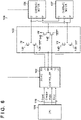
Fig. 6 is a diagram showing the more specific details of a relationship between thecontrol line 110, acontrol unit 102, adriving unit 103, andphase information 108 from acarriage motor 104; -
Fig. 7 is a view showing a truth table of control signals of thecontrol unit 102; -
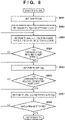
Fig. 8 is a flowchart showing operation control of carriage (CR) motors; -
Fig. 9 is a block diagram showing the motor control arrangement of a printing apparatus according toModification 1 of the first embodiment; -
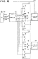
Fig. 10 is a diagram showing the more specific details of a relationship between thecontrol line 110, thecontrol unit 102, adriving unit 111, adriving unit 112, and thephase information 108 from thecarriage motor 104; -
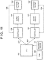
Fig. 11 is a block diagram showing the motor control arrangement of a printing apparatus according toModification 2 of the first embodiment; -
Fig. 12 is a diagram showing the more specific details of a relationship between acontrol line 201, acontrol line 202, acontrol unit 130, acontrol unit 131, thedriving unit 111, thedriving unit 112, thephase information 108 from thecarriage motor 104, andphase information 109 from acarriage motor 109; -
Fig. 13 is a block diagram showing the motor control arrangement of a printing apparatus according to the second embodiment; -
Fig. 14 is a flowchart showing a carriage motor confirmation sequence; -
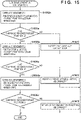
Fig. 15 is a flowchart showing a carriage motor confirmation sequence according toModification 1 of the second embodiment; -
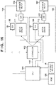
Fig. 16 is a block diagram showing the motor control arrangement of a printing apparatus according toModification 2 of the second embodiment; -
Fig. 17 is a block diagram showing the motor control arrangement of a printing apparatus according toModification 3 of the second embodiment; and -
Fig. 18 is a perspective view showing the structure near the recovery unit of the printing apparatus shown inFig. 1 , and is a view showing a state in which the recovery unit has been removed from the printing apparatus. - Preferred embodiments of the present invention will be further described in detail with reference to the accompanying drawings. Note that the following embodiments do not limit the invention according to the scope of the appended claims. Although a plurality of features are described in the embodiments, not all of the features are essential to the invention and the plurality of features may arbitrarily be combined. Furthermore the same reference numerals denote the same or similar parts in the accompanying drawings, and a repetitive description thereof will be omitted.
- Note that in this specification, the term "printing" (to be also referred to as "print" hereinafter) not only includes the formation of significant information such as characters and graphics, regardless of whether they are significant or insignificant. Furthermore, it broadly includes the formation of images, figures, patterns, and the like on a print medium, or the processing of the medium, regardless of whether they are so visualized as to be visually perceivable by humans.
- In addition, the term "print medium" not only includes a paper sheet used in common printing apparatuses, but also broadly includes materials, such as cloth, a plastic film, a metal plate, glass, ceramics, wood, and leather, capable of accepting ink.
- Furthermore, the term "ink" (to also be referred to as a "liquid" hereinafter) should be extensively interpreted similarly to the definition of "printing (print)" described above. That is, "ink" includes a liquid which, when applied onto a print medium, can form images, figures, patterns, and the like, can process the print medium, or can process ink (for example, solidify or insolubilize a coloring material contained in ink applied to the print medium).
- Further, a "nozzle" generically means an orifice or a liquid channel communicating with it, and an element for generating energy used to discharge ink, unless otherwise specified.
-
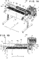
Figs. 1A and 1B are outer appearance views showing the schematic arrangement of an inkjet printing apparatus according to a representative embodiment of the present invention.Fig. 1A shows a perspective view showing the schematic arrangement of an inkjet printing apparatus 100 (to be referred to as a printing apparatus hereinafter), andFig. 1B shows a top view thereof. - In addition,
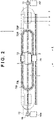
Fig. 2 is an explanatory view showing the structure of the periphery of a carriage of the printing apparatus. - In
Figs. 1A, 1B , and2 , arrows X, Y, and Z indicate the front-and-rear direction (a depth direction), the left-and-right direction (widthwise direction as the longitudinal direction of the apparatus), and the upper-and-lower direction (the vertical direction or the direction of gravity),respectively. In addition, "F", "B", "L", and "R" indicate the front side, the rear side, the left side, and the right side, respectively. - The
printing apparatus 100 includes a printing unit including aprinthead 2 and acarriage 3. A plurality of discharge orifices (nozzles) are formed on theprinthead 2, and a plurality of channels are formed in theprinthead 2 so as to communicate with the respective discharge orifices. An inkjet-method energy generating element such as a heater, a piezoelectric element, or the like is arranged in each of the plurality of channels, and ink droplets are discharged from the corresponding discharge orifice by the inkjet method.Ink tanks 5 containing inks to be supplied to theprinthead 2 are arranged in positions separate from the printing unit. Note that the printing method is not limited to the inkjet method, and a printhead of another printing method may also be used. - A
carriage motor 104 and acarriage motor 107 each connected to a drivingpulley 19 are arranged at both ends of a range of movement of thecarriage 3. A description will be made here by assuming that thecarriage motor 104 and thecarriage motor 107 arranged at both ends have similar characteristics including thedriving pulleys 19. Atiming belt 7 is suspended and arranged between the two carriage motors, and thecarriage 3 is attached to a part of thetiming belt 7. Thecarriage 3 can be made to scan by these components. By using two carriage motors to drive thecarriage 3 in this manner, it will be possible to increase the output more than when a carriage is driven by a single carriage motor, and even a heavyweight carriage will be able to be scanned at a high speed. - The
printing apparatus 100 also includes a position detection mechanism for detecting the position of thecarriage 3. Such a position detection mechanism includes alinear scale 13 extending in a carriage scanning direction and anencoder sensor 14 which is mounted on thecarriage 3 and reads slits provided in thelinear scale 13. The position control/speed control of thecarriage 3 can be performed by feeding back an encoder signal detected by this position detection mechanism. - The
carriage 3 on which theprinthead 2 is mounted is guided by aguide rail 11 and aguide rail 12 and is supported by a main body of theprinting apparatus 100. Theguide rail 11 and theguide rail 12 are supported by amain body frame 10. Thecarriage 3 reciprocally moves along an extending direction of theguide rail 11 and theguide rail 12. A direction in which thecarriage 3 is scanned toward the L side and a direction in which thecarriage 3 is scanned toward the R side inFigs. 1A, 1B , and2 will be described as "a forward direction" and "a reverse direction", respectively, hereinafter. In addition, regardless of the forward direction and the reverse direction, a direction in which thecarriage 3 moves will be referred to as a main scanning direction. - A
rolled sheet 1 as a print medium is set in a sheet feeding unit. Theprinting apparatus 100 includes aconveyance roller 4 which is rotationally driven and apinch roller 9 which rotates by being driven by theconveyance roller 4. Aplaten 6 supports thesheet 1 in a position facing the printing unit. Thesheet 1 is conveyed in a state in which thesheet 1 is sandwiched between theconveyance roller 4 and thepinch roller 9. A printing operation of discharging ink toward thesheet 1 on theplaten 6 while thecarriage 3 on which theprinthead 2 is mounted is moved in the main scanning direction, and a conveying operation of conveying thesheet 1 in a sheet conveyance direction (sub-scanning direction) stepwise are performed. An image is printed on a sheet in accordance with a serial printing method by repetitively performing the printing operation and the conveying operation. - Note that the reference of the
carriage 3 and the sheet is set on the side of theink tanks 5. That is, the position of the end portion of the sheet on the refence side will not change even if the width of the sheet changes. In addition, arecovery unit 120 is arranged on the reference side. Therecovery unit 120 includes acap 121 for sealing the surfaces of discharge orifices formed in theprinthead 2. An in-cap absorbing member is provided in thecap 121 to receive and absorb ink discharged during a preliminary ink discharge operation (preliminary discharge) performed to prevent discharge failure of theprinthead 2. -
Fig. 18 is a perspective view showing a structure near therecovery unit 120 of theprinting apparatus 100 shown inFig. 1 .Fig. 18 shows a state in which therecovery unit 120 is attached to theprinting apparatus 100. - The
cap 121 for sealing the surfaces of the discharge orifices formed on theprinthead 2 is provided on therecovery unit 120 as described above. An in-cap absorbing member is provided in thecap 121 to receive and absorb ink discharged during a preliminary ink discharge operation (preliminary discharge) performed to prevent discharge failure of theprinthead 2. - The
cap 121 is connected to a suction pump and a tube, and sucks ink or air from the surfaces of the discharge orifices of theprinthead 2, as needed, to clean the discharge orifices and to remove air accumulated in the printhead. A wiper member is also provided to remove ink or dirt that has adhered to the surfaces of the discharge orifices of theprinthead 2. In addition, a discharge failure detection unit is arranged beside therecovery unit 120, and the discharge failure detection unit includes a sensor for detecting whether ink is being correctly discharged from each discharge orifice of theprinthead 2. - Since the
recovery unit 120 will perform a recovery operation on theprinthead 2 which is mounted on thecarriage 3, therecovery unit 120 will be arranged outside the width of asheet 1 but also be arranged inside the scanning range of thecarriage 3. As shown inFig. 18 , amotor support member 201 is attached to amotor attachment plate 202, and is formed to be integrally attachable/detachable as atension applying unit 200 for applying tension to thetiming belt 7. In addition, thetension applying unit 200 is fixed to the main body frame byscrews 206. Also, a protrudingshape 10b and a protrudingshape 10d are provided in themotor attachment plate 202. Thetension applying unit 200 also includes thecarriage motor 107 and is arranged outside the scanning range of thecarriage 3. - Hence, as shown in
Fig. 18 , thetension applying unit 200 is arranged outside therecovery unit 120, which is arranged inside the scanning range of thecarriage 3, and thetension applying unit 200 is fixed to the main body frame by thescrews 206. Furthermore, as is obvious fromFig. 18 , theink tanks 5 and therecovery unit 120 are arranged on the reference side of thecarriage 3. - Each of a
tube 73R and atube 73L is a tube formed by a plurality of flexible ink tubes for supplying inks of a plurality of colors from theink tanks 5 fixed to the side of the main body of theprinting apparatus 100 to theprinthead 2 on thecarriage 3. Thetube 73R is provided so that its R side will be U-shaped in the Y direction by fixing its one end to thecarriage 3 and its other end to a connectingmember 70 which is fixed to the side of the main body of theprinting apparatus 100. In a similar manner, thetube 73L is also provided so that its L side will be U-shaped in the Y direction. In this example, thetube 73R and thetube 73L are installed to have the same number of bundled tubes, the same length, the same material, and the like as each other, and have only different curving directions from each other. - In addition, to guide the deformation of the
tube 73R and thetube 73L which accompanies the reciprocal movement of thecarriage 3, theprinting apparatus 100 includestube holding members tube holding members carriage 3. In this example, thetube holding members tube 73R is inserted in thetube holding member 78R, and thetube 73L is inserted in thetube holding member 78L. - Several embodiments of a more specific method for driving the
carriage 3 by using theprinting apparatus 100 according to the above-described arrangement will be described next. -
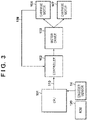
Fig. 3 is a block diagram showing the motor control arrangement of a printing apparatus according to the first embodiment. - A
carriage motor 104 and acarriage motor 107 shown inFig. 3 are brushless DC motors. ACPU 101 controls, via acontrol line 110, a control unit (controller) 102 based on a signal from acommon encoder sensor 14. Also, thecontrol unit 102 controls a driving unit (motor driver) 103 based on signals from thecontrol line 110 andphase information 108 from thecarriage motor 104. Subsequently, each of thecarriage motor 104 and thecarriage motor 107 performs a predetermined operation based on a driving signal from the drivingunit 103. AROM 120 stores pieces of information that indicate the speed of acceleration/deceleration corresponding to the print medium or a print mode, a constant speed, a distance until a stop, and the like. - Details of the motor control arrangement shown in
Fig. 3 will be described next with reference toFigs. 4 to 7 . -
Fig. 4 is a view showing a carriage speed profile and the details of control signals included in thecontrol line 110. - The
control line 110 includes, as shown inFig. 4 , a reset signal (Reset), a direction signal (Direction), a PWM signal, and a brake signal (Brake), and thecarriage motor 104 and thecarriage motor 107 are controlled by the same control signal. - The reset signal controls whether each carriage motor is to be operated. In this embodiment, each carriage motor will not be able to operate when the reset signal is at high level (a period R-A in
Fig. 4 ), and each carriage motor will be able to operate when the reset signal is at low level (a period R-B inFig. 4 ). - The direction signal controls the direction of the operation of each carriage motor. In this embodiment, the
carriage 3 will move in the forward direction when the direction signal is at high level (a period D-A inFig. 4 ), and thecarriage 3 will move in the reverse direction when the direction signal is at low level (a period D-B inFig. 4 ). Note that an operation in the forward direction and an operation in the reverse direction are, more specifically, operations in the rotation directions of each carriage motor, and the forward direction and the reverse direction have opposite rotation directions from each other. Each carriage motor is formed by a three-phase coil and can change the aforementioned rotation direction by controlling a voltage supplied to each of coil voltage terminals U, V, and W shown inFig. 6 . - The PWM signal controls the amount of energy supplied to each of the coil voltage terminals U, V, and W of each carriage motor. The amount of energy supplied to each coil voltage terminal is determined by an ON/OFF ratio (to be referred to as a PWM duty cycle hereinafter). The coil voltage will increase as the PWM duty cycle increases, thereby causing the carriage motor to rotate at a higher speed. In this embodiment, assume that a predetermined cycle is 10 kHz (each broken line interval shown in
Fig. 4 ). A period in which the PWM duty cycle is greater than 50% is an acceleration period (a period P-A inFig. 4 ) of each carriage motor, a period in which the PWM duty cycle is 50% is a constant speed period (a period P-B inFig. 4 ), and a period in which the PWM duty cycle is less than 50% is a deceleration period (a period P-C inFig. 4 ). - The brake signal is a signal for stopping each carriage motor, and stop control is performed when the brake signal is at high level in this embodiment (a period B―A in
Fig. 4 ). More specifically, the operation of thecarriage 3 will be stopped by controlling the voltage applied to each of the coil voltage terminals U, V, and W of each carriage motor so that the movement of thecarriage 3 will change to an operation in the reverse direction if thecarriage 3 is moving in the forward direction. - The control time and the control waveform of each of the direction signal, the PWM signal, and the brake signal described above are determined based on a signal from the
common encoder sensor 14. Here, the signal (encoder signal) from theencoder sensor 14 is generated by alinear scale 13 and theencoder sensor 14 shown inFig. 2 . -
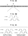
Figs. 5A to 5C are views for explaining the relationship between the linear scale and the encoder sensor, and the encoder signal output from the encoder sensor. - By causing, as shown in
Fig. 5A , theencoder sensor 14 to read the slits formed on thelinear scale 13, two encoder signals (an A phase and a B phase) whose phases are shifted from each other by 90° are generated as shown inFig. 5B . Each signal is input to theCPU 101, and the number of pulses of the signal can be counted to obtain the position of thecarriage 3 that has been driven by the carriage motors. In addition, the speed of thecarriage 3 can be calculated based on the cycle of each encoder signal. Furthermore, the direction of movement of thecarriage 3 can be calculated from the phase state of each encoder signal. - In this embodiment, as shown in
Fig. 5C , it will be determined that the carriage is moving in the forward direction if the A-phase signal rises when the B-phase signal is at high level, and it will be determined that the carriage is moving in the reverse direction if the A-phase signal rises when the B-phase signal is at low level. -
Fig. 6 is a diagram showing the more specific details of a relationship between thecontrol line 110, thecontrol unit 102, the drivingunit 103, and thephase information 108 from thecarriage motor 104. -
Fig. 7 is a view showing a truth table of the control signals of thecontrol unit 102. - The driving unit (driver) 103 is formed by, as shown in
Fig. 6 , power supply lines VM,FETs 141 to 143, andFETs 144 to 146, and is connected to thecarriage motor 104 and thecarriage motor 107. Also, thephase information 108 is formed by three signals, and the signals are input to terminals HI, H2, and H3 of the control unit (controller) 102. - The
phase information 108 indicates the position information of the coil in thecarriage motor 104, and a signal of 0 (low voltage) or 1 (high voltage) will be input. Each of terminals HA to HC and terminals LA to LC of thecontrol unit 102 is connected to the gate of the corresponding one ofFETs 141 to 146 of thedriving unit 103, and the driving of each FET is controlled by a signal of 0 (low voltage) or 1 (high voltage). The outputs from the terminals HA, LA, HB, LB, HC, and LC of thecontrol unit 102 are controlled by the combinations of thephase information 108 and the control signals as shown inFig 7 . As a result, theFETs 141 to 143 and theFET 144 toFET 146 will be set to ON or OFF and the voltages applied to the coil voltage terminals U, V, and W of each carriage motor will be controlled, thus allowing the carriage to operate at an arbitrary speed and in an arbitrary direction. - The operation of the carriage motors having the arrangement described above with reference to
Figs. 4 to 7 will be described next with reference to a flowchart. -
Fig. 8 is a flowchart showing the operation control of carriage (CR) motors. An example in which the twocarriage motors carriage 3 in the forward direction will be described here. Note that the control for moving thecarriage 3 in the reverse direction will also be performed in a similar manner. - When the control to operate the carriage motors in the forward direction is started, the
CPU 101 sets, in step S801, the reset signal to low level (the period R-AinFig. 4 ). Next, in step S802, the stopped state of the carriage is canceled by setting the direction signal to high level and simultaneously setting the brake signal to low level (the period D-A inFig. 4 ). - Next, in step S803, the PWM signal is output at 80% duty cycle, and the
carriage 3 starts the operating in the forward direction (the period P-A inFig. 4 ). As is obvious from the carriage speed profile ofFig. 4 , thecarriage 3 is accelerated. TheCPU 101 simultaneously counts the number of pulses of each encoder signal, and starts calculating the carriage speed based on the pulse intervals. - In addition, in step S804, the
CPU 101 checks whether the carriage speed has reached a target speed V stored in therecovery unit 120. If it is determined that the carriage speed has reached the target speed V, the process will advance to step S805 to change the duty cycle of the PWM signal to 50% to make thecarriage 3 move at a constant speed (the period P-B inFig. 4 ). As is obvious from the carriage speed profile ofFig. 4 , thecarriage 3 will shift from moving at an accelerated speed to moving at a constant speed. In contrast, if it is determined that the carriage speed has not reached the target speed V, the process will return to step S803 to continue the carriage control by maintaining the PWM signal at 80% duty cycle. - In step S806, whether the carriage position has reached a stop start position P is checked. Note that the stop start position P is calculated by subtracting a distance to a stop position stored in the
ROM 120 from a carriage target stop position Y, which is calculated by theCPU 101 from the carriage speed or the printing width. If it is determined here that the carriage position has not reached the stop start position P, the process will return to step S805 to continue the constant speed movement control executed on the carriage in a state in which the PWM signal is maintained at 50% duty cycle. In contrast, if it is determined that the carriage position has reached the stop start position P, the process will advance to step S807 to stop the operation to move thecarriage 3 by setting the duty cycle of the PWM signal to 20% and the brake signal to high level (the period P-C inFig. 4 ). As is obvious from the carriage speed profile ofFig. 4 , thecarriage 3 will shift from moving at an accelerated speed to moving at a decelerated speed. - In step S808, whether the
carriage 3 has stopped is checked. If it is confirmed, based on the output of the encoder signals, that the position of thecarriage 3 has not changed, that is, the carriage has stopped, the control for moving the carriage in the forward direction will end. In contrast, if it is determined that thecarriage 3 has not stopped, the process will return to step S807 to continue the control to decelerate the carriage. - Note that the value of the duty setting of the PWM signal is not particularly limited since the duty setting will change based on the target carriage speed, the acceleration speed during the time of acceleration/deceleration, or the like. In addition, the procedure of the operation to be performed for a movement in the reverse direction is also similar to that of the operation performed for the movement in the forward direction.
- Hence, according to the embodiment described above, by arranging a common control line, a common control unit, and a common driving unit, it will be possible to reduce the circuit area and to simplify the control method. As a result, good control responsiveness and good control stability can be obtained even in an arrangement using one set of (two) carriage motors to drive a heavyweight carriage, and it will be possible to implement a high-speed and high-accuracy carriage driving operation.
- Note the carriage motor is not limited to a brushless DC motor and may be, other than a DC motor such as a brushless DC motor, a stepping motor or the like. The form (type) of the carriage motors is not limited as long as motors that can drive a carriage and motors having similar kinds of driving characteristics are used for both left and right ends.
- In addition, although an arrangement in which the
control unit 102 controls thecommon driving unit 103 by using the signals of thecontrol line 110 and thephase information 108 from thecarriage motor 104 has been described, it may be arranged so that the control will be performed based on the phase information from thecarriage motor 107. - In addition, as long as identical signals are output to the
control line 110, it may be arranged so that the signals will be output from the same terminal or from separate terminals from theCPU 101. - Furthermore, although the embodiment described above has an arrangement in which driving control can be performed easily by arranging so that the plurality of
carriage motors pulley 19 will have similar characteristics, the present invention is not limited to this. For example, the left and right driving pulleys 19 may have different diameters from each other or the outputs from thecarriage motor 104 and thecarriage motor 107 may differ even if the driving characteristics of these motors are similar. - Although a single controller and a single motor driver were used in the motor control arrangement of the printing apparatus according to the first embodiment shown in
Fig. 3 , an arrangement that uses motor drivers corresponding to two carriage motors may also be employed. Furthermore, an arrangement using two controllers may also be employed. Two modifications which are an arrangement that uses a single control unit (controller) and two driving units (motor drivers) and an arrangement that uses two control units (controllers) and two driving units (motor drivers) will be described hereinafter. -
Fig. 9 is a block diagram showing the motor control arrangement of a printing apparatus according toModification 1 of the first embodiment. Note that inFig. 9 , the same reference numerals denote components similar to those already described with reference toFig. 3 , and a description thereof will be omitted. - According to
Fig. 9 , thecontrol unit 102 controls, based on the signals of thecontrol line 110 and thephase information 108 from thecarriage motor 104, a driving unit (motor driver) 111 and a driving unit (motor driver) 112. Next, thecarriage motor 104 and thecarriage motor 107 perform predetermined operations based on driving signals generated based on the ON/OFF states of the FETs of thedriving unit 111 and those of thedriving unit 112. -
Fig. 10 is a diagram showing the more specific details of the relationship between thecontrol line 110, thecontrol unit 102, the drivingunit 111, the drivingunit 112, and thephase information 108 from thecarriage motor 104. Note that inFig. 10 , the same reference numerals denote components similar to those already described with reference toFig. 6 , and a description thereof will be omitted. - Although the control method of the carriage motor of this modification is similar to that of the first embodiment, the driving
unit 111 is connected to thecarriage motor 104 and formed by the power supply lines VM,FETs 131 to 133, andFETs 134 to 136. The drivingunit 112 is connected to thecarriage motor 107 and formed by the power supply lines VM,FETs 137 to 139, andFETs 140 to 142. The two driving units have the same circuit arrangement in this manner. - As shown in
Fig. 10 , in the arrangement of this modification, thecontrol line 110 and thecontrol unit 102 are arranged in common for the driving control of the two carriage motors, and each of two driving units is connected to a corresponding one of the carriage motors. - By employing such an arrangement, the electric power load on each driving unit can be reduced by half, thereby allowing reduction of costs necessary for measures against heat.
-
Fig. 11 is a block diagram showing the motor control arrangement of a printing apparatus according toModification 2 of the first embodiment. Note that inFig. 11 , the same reference numerals denote components similar to those already described with referenceFigs. 3 and9 , and a description thereof will be omitted. - According to
Fig. 11 , theCPU 101 controls a control unit (controller) 130 and a control unit (controller) 131 by acontrol line 201 and acontrol line 202, respectively. Note that in this modification, thecontrol lines control unit 130 and thecontrol unit 131 control the drivingunit 111 and thedriving unit 112, respectively, based on signals from thecontrol line 201 and thecontrol line 202, thephase information 108 from thecarriage motor 104 andphase information 109 from thecarriage motor 107. Subsequently, thecarriage motor 104 and thecarriage motor 107 perform predetermined operations based on driving signals generated based on the ON/OFF states of the FETs of thedriving unit 111 and those of thedriving unit 112. -
Fig. 12 is a diagram showing in the more specific details of the relationship between thecontrol line 201, thecontrol line 202, thecontrol unit 130, thecontrol unit 131, the drivingunit 111, the drivingunit 112, thephase information 108 from thecarriage motor 104, and thephase information 109 from thecarriage motor 107. Note that inFig. 12 , the same reference numerals denote components similar to those already described with reference toFigs. 6 and10 , and a description thereof will be omitted. - The control method of the carriage motors of this modification is similar to that of the first embodiment, and the arrangements of the two drivers are similar to those of
Modification 1. As shown inFig. 12 , in the arrangement of this modification, thecontrol line 201 and thecontrol line 202 are arranged in common, and each carriage motor is connected to a corresponding control unit and a corresponding driving unit. In addition, the two controllers have the same arrangement. - By employing such an arrangement, the electric power load on each driving unit can be reduced by half, thereby allowing reduction of costs necessary for measures against heat. In addition, in this modification, since control will be performed by inputting each of the pieces of
phase information 108 and thephase information 109 of the respective carriage motors to the corresponding one of the control units, each carriage motor can be controlled more accurately. - Furthermore, by employing such an arrangement, it will be possible to make, while using a signal from the
same encoder sensor 14, an arbitrary carriage motor operate by arranging a control line for each carriage motor. As a result, for example, it will be possible execute control to change the power ratio (for example, 60 : 40 or the like) between thecarriage motor 104 and thecarriage motor 107, thereby allowing a more precise motor control operation to be implemented. - Two carriage motors were simultaneously driven in the first embodiment. However, in practice, in a case in which the carriage will not execute a high-speed movement, for example, when executing printing up to a speed of 70 ips or when performing an operation other than printing, the carriage can also be operated by driving one carriage motor while making the other carriage motor follow.
- Hence, in such aforementioned driving operation, it is impossible to discriminate whether each carriage motor is operating normally.
- Therefore, this embodiment will describe an example in which the carriage motors will be driven one by one at separate timings to confirm whether each carriage motor is operating normally.
-
Fig. 13 is a block diagram showing the motor control arrangement of a printing apparatus according to the second embodiment. Note that inFig. 13 , the same reference numerals denote the same components similar to those already described with reference toFig. 3 , and a description thereof will be omitted. - As is obvious from comparing
Figs. 13 and3 , the basic arrangement is similar to the arrangement according to the first embodiment shown inFig. 3 . However, in this case, a switch (SW) 161 and a switch (SW) 162 are arranged on a control line between two carriage motors and adriving unit 103. ACPU 101 will perform ON/OFF control on each of theswitch 161 and theswitch 162 via corresponding individual control lines. - Processing for using such an arrangement to confirm whether each of
carriage motors -
Fig. 14 is a flowchart showing a carriage motor confirmation sequence. - By executing this sequence, the carriage motors will be operated individually to confirm whether each carriage motor is not operating abnormally. A detailed description will be given hereinafter with reference to
Fig. 2 which shows target positions a, b, and c of a carriage in this sequence. - First, in step S1601, parameters L and R which indicate whether the two carriage motors are normal or abnormal are reset to L = 0 and R = 0. Next, in step S1602, in a state in which a
carriage 3 is at its movement origin point (a home position or an initial position) which is indicated as "0" inFig. 2 , only thecarriage motor 104 is driven. More specifically, an operation command in which "a" indicated inFig. 2 is set as a target position and the carriage speed is set to 35 ips is issued and only theswitch 161 is set to ON to make thecarriage 3 operate in the forward direction. Note that in this embodiment, the resolution of the slits formed on alinear scale 13 is 1,200 dpi, and the target position a corresponds to a point at 2,000 slits (= 42. 3 mm) from theorigin point 0 when measured by the number of slits provided on the linear scale. - Next, in step S1603, whether the
carriage 3 was able to move is confirmed. Although this is confirmed by determining whether thecarriage 3 was able to move 1,000 (= 21.2 mm) slits or more within 5 sec of the start of the driving operation of the motor, the present invention is not limited to this. For example, it may be confirmed by checking whether an encoder signal was detected at an expected time at the target position a. If it is determined here that thecarriage 3 was not able to move, the process will advance to step S1604 to set L = 1, and the process will subsequently advance to step S1605. In contrast, if it is determined that thecarriage 3 was able to move, the parameter L will remain at L = 0, and the process will advance to step S1605. - Next, in the process of step S1605, only the
carriage motor 107 is driven. More specifically, an operation command in which "b" indicated inFig. 2 is set as a target position and the carriage speed is set to 35 ips is issued, and only theswitch 162 is set to ON to make thecarriage 3 operate in the forward direction. Note that the target position b corresponds to a point at 4,000 slits (= 84.7 mm) from theorigin point 0 when measured by the number of slits provided on the linear scale. - Subsequently, in step S1606, whether the
carriage 3 was able to move is confirmed. This is confirmed by determining whether thecarriage 3 was able to move 1,000 (= 21.2 mm) slits or more within 5 sec of the start of the driving operation of the motor, the present invention is not limited to this. For example, it may be confirmed by checking whether an encoder signal was detected at an expected time at the target position b. If it is determined here that thecarriage 3 was not able to move, the process will advance to step S1607 to set R = 1, and the process will subsequently advance to step S1608. In contrast, if it is determined that thecarriage 3 was able to move, the parameter R will remain at R = 0, and the process will advance to step S1608. - Next, in the process of step S1608, whether the values of the two parameters are L = 0 and R = 0 is checked. If the two parameters are L = 0 and R = 0, it will be determined that both the two
carriage motors - If the two parameters are L = 1 and R = 0, the process will advance to step S1610 to determine that the
carriage motor 104 is abnormal, and the user will be notified of this abnormality. The notification will be performed by displaying a message on an operation panel (not shown) of aprinting apparatus 100, by transmitting error information to a host apparatus (not shown) connected to theprinting apparatus 100 to display an error message on a display of the host apparatus, or the like. For example, a failure in a wiring line to thecarriage motor 104, a failure of thecarriage motor 104 itself, or the like can be considered to be a cause of the abnormality in this case. - In contrast, if the two parameters are not L = 1 and R = 0, the process will advance to step S1611 to check whether the values of the two parameters are L = 0 and R = 1. If the two parameters are L = 0 and R = 1, the process will advance to step S1612 to determine that the
carriage motor 107 is abnormal, and the user will be notified of this abnormality. This notification is performed in a manner similar to the notification method performed in step S1610. For example, a failure in a wiring line to thecarriage motor 107, a failure of thecarriage motor 107 itself, or the like can be considered to be a cause of the abnormality in this case. - In contrast, if the two parameters are not L = 0 and R = 1 (that is, the two parameters are L = 1 and R = 1), the process will advance to step S1613 to determine that the
carriage 3 cannot move because an obstacle or the like is present in the periphery of thecarriage 3, and the user will be notified of this determination. This notification is performed in a manner similar to the notification method performed in step S1610. - The confirmation sequence will also be ended after step S1610, step S1612, or the notification in step S1613.
- Note that after step S1610, step S1612, or the notification in step S1613, the user may turn off the
printing apparatus 100 and turn on theprinting apparatus 100 again to cause the initialization operation to be executed again. If the abnormality of thecarriage motor 104 is unsolved even after this operation, the periphery of thecarriage motor 104 will be checked or components will be replaced. On the other hand, if the abnormality of thecarriage motor 107 is unsolved even after this operation, the periphery of thecarriage motor 107 will be checked or components will be replaced. In a case in which the state in which the carriage cannot move is unsolved, the periphery of thecarriage 3 will be checked or components of the carriage unit will be replaced. - Note that in this embodiment, the operation commands to the
carriage motors linear scale 13 are performed to confirm, by issuing a motor operation command, whether the detection by anencoder sensor 14 has changed and thecarriage 3 can move a predetermined amount or more. In this case, while operating thecarriage 3 in the forward direction, it will be possible to make a determination in a continuous operation without stopping thecarriage 3 for each determination. - Furthermore, the target positions of the carriage and the carriage speed described above are merely examples, and other target positions and another carriage speed may also be used.
- According to the above-described confirmation sequence, in a printing apparatus that uses a plurality of carriage motors to operate a carriage, whether each of the plurality of carriage motors is operating normally can be reliably detected without making the carriage operate at a high speed.
- Another example of confirming whether the
individual carriage motors carriage 3 and operating each carriage motor after using both carriage motors to operate thecarriage 3. Note that in this modification, it will be assumed that the arrangement shown inFig. 13 is used as the motor control arrangement of the printing apparatus. -
Fig. 15 is a flowchart showing the carriage motor confirmation sequence according toModification 1 of the second embodiment. A detailed description will be given hereinafter with reference toFig. 2 which shows the target positions a, b, and c of the carriage in this sequence. Note that inFig. 15 , the same step numbers are used to denote the same processing steps as those already described with reference toFig. 13 , and a description thereof will be omitted. - According to
Fig. 15 , in step S1602a, both thecarriage motors carriage 3 is at its movement origin point (the home position or the initial position) which is indicated as "0" inFig. 2 . More specifically, an operation command in which "a" indicated inFig. 2 is set as a target position and the carriage speed is set to 35 ips is issued, and both of theswitches carriage 3 operate in the forward direction. Note that in this example, the resolution of the slits formed on alinear scale 13 is 1,200 dpi, and the target position a corresponds to a point at 2,000 slits (= 42. 3 mm) from theorigin point 0 when measured by the number of slits provided on the linear scale. - Next, in step S1603a, whether the
carriage 3 has reached the target position a is confirmed. This is confirmed by determining whether thecarriage 3 is within ±30 slits (= ±0.625 mm) of the target position within 5 sec. However, the present invention is not limited to this. For example, this may be confirmed by checking whether an encoder signal is detected at an expected time T±Δt at the target position a. If it is determined here that thecarriage 3 has not reached the target position a, it will be determined that thecarriage 3 is unable to move because an obstacle is present in the periphery of thecarriage 3, the process will advance to step S1613, and the processing will subsequently end. In contrast, if it is determined that thecarriage 3 has reached the target position a, the process will advance to step S1605a. - In step S1605a, only the
carriage motor 104 is driven. More specifically, an operation command in which "b" indicated inFig. 2 is set as a target position and the carriage speed is set to 35 ips is issued, and only theswitch 161 is set to ON to make thecarriage 3 operate in the forward direction. The target position b corresponds to a point at 4,000 slits (= 84.7 mm) from theorigin point 0 when measured by the number of slits provided on the linear scale. Subsequently, in step S 1606a, whether thecarriage 3 has reached the next target position b is confirmed. This is confirmed by determining whether thecarriage 3 is within ±30 slits (= ±0.625 mm) of the target position within 5 sec. However, the present invention is not limited to this. For example, this may be confirmed by checking whether an encoder signal is detected at the expected time T±Δt at the target position b. If it is determined here that thecarriage 3 has not reached the target position b, the process will advance to step S1610, and the processing will subsequently end. In contrast, if it is determined that thecarriage 3 has reached the target position b, the process will advance to stepS 1606b. - In step S1606b, only the
carriage motor 107 is driven. More specifically, an operation command in which "c" indicated inFig. 2 is set as a target position and the carriage speed is set to 35 ips is issued, and only theswitch 162 is set to ON to make thecarriage 3 operate in the forward direction. The target position c corresponds to a point at 6,000 slits (= 127 mm) from theorigin point 0 when measured by the number of slits provided on the linear scale. Subsequently, in step S 1606c, whether thecarriage 3 has reached the next target position c is confirmed. This is confirmed by determining whether thecarriage 3 is within ±30 slits (= ±0.625 mm) of the target position within 5 sec. However, the present invention is not limited to this. For example, this may be confirmed by checking whether an encoder signal is detected at the expected time T±Δt at the target position c. - If it is determined here that the
carriage 3 has not reached the target position c, the process will advance to step S1612, and the processing will subsequently end. In contrast, if it is determined that thecarriage 3 has reached the target position c, the processing will be end because it has been confirmed that thecarriage motors - Therefore, according to the embodiments and the modifications described above, even in a printing apparatus that uses a plurality of carriage motors to operate a carriage, whether each of the plurality of carriage motors is operating normally can be reliably detected without making the carriage operate at a high speed.
- Note that although this modification employed a confirmation method in which the
carriage 3 is operated repeatedly in the forward direction, a method in which thecarriage 3 is operated and stopped in the reverse direction after thecarriage 3 has been operated and stopped in the forward direction may also be employed. -
Fig. 16 is a block diagram showing the motor control arrangement of a printing apparatus according toModification 2 of the second embodiment. As is obvious from comparingFigs. 16 and9 , this control arrangement is an arrangement in which switches and control lines have been added to the motor control arrangement of the printing apparatus according toModification 1 of the first embodiment shown inFig. 9 . - Note that in
Fig. 16 , the same reference numerals denote components similar to those already described with reference toFigs. 3 and9 , and a description thereof will be omitted. Even by employing this kind of arrangement, it will be possible to drive only one of the twocarriage motors - As shown in
Fig. 16 , switches (SWs) 177 and 178 are arranged on the control lines from drivingunits CPU 101 can individually execute ON/OFF control on each of theswitches - Furthermore, it may be arranged so that the
CPU 101 will control the drivingunits units - By using the motor control arrangement described above, it will be possible to execute a sequence for confirming individual carriage motors as described with reference to
Figs. 14 and15 . -
Fig. 17 is a block diagram showing the motor control arrangement of a printing apparatus according toModification 3 of the second embodiment. As is obvious from comparingFigs. 17 and11 , this control arrangement is an arrangement in which switches and control lines have been added to the motor control arrangement of the printing apparatus according toModification 2 of the first embodiment shown inFig. 1 . - Note that in
Fig. 17 , the same reference numerals denote components similar to those already described with reference toFigs. 3 and11 , and a description thereof will be omitted. Even by employing this kind of arrangement, it will be possible to drive only one of the twocarriage motors - As shown in
Fig. 17 , switches (SWs) 171 and 172 are arranged on the control lines from drivingunits CPU 101 can individually execute ON/OFF control on each of theswitches - Furthermore, it may be arranged so that the
CPU 101 will control the drivingunits units - By using the motor control arrangement described above, it will be possible to execute a sequence for confirming individual carriage motors as described with reference to
Figs. 14 and15 . - In addition, in each of the embodiments and the modifications described above, it is preferable for a
timing belt 7,tubes tube holding members carriage 3. That is, this indicates a state in which these components are wound to have a bilaterally symmetrical arrangement, upon being viewed from the front and the top direction with respect to thecarriage 3 as the origin, when thecarriage 3 is positioned at the approximate center of its maximum movement range as shown inFig. 2 . Since this will make the load from the movement of the carriage in the forward direction and the load from the movement of the carriage in the reverse direction be approximately the same, the loads on thecarriage motors carriage motors - Furthermore, although each of the embodiments and the modifications described above described an example of a printing apparatus that performs printing by reciprocally moving a carriage on which a printhead is mounted, the present invention is not limited to this. The present invention can be applied to, for example, a scanner apparatus that reads an image of an original by reciprocally moving a scanner on which a contact image scanner (CIS) is mounted, a multifunction printer incorporating both this scanner apparatus and the printing apparatus, and the like.
- The present invention is not limited to the above embodiments and various changes and modifications can be made within the spirit and scope of the present invention. Therefore, to apprise the public of the scope of the present invention, the following claims are made.
- While the present invention has been described with reference to exemplary embodiments, it is to be understood that the invention is not limited to the disclosed exemplary embodiments. The scope of the following claims is to be accorded the broadest interpretation so as to encompass all such modifications and equivalent structures and functions.
- A carriage apparatus characterized by comprising a carriage configured to reciprocally move in a predetermined direction, a first motor arranged on a side of one end of a range of movement of the carriage and configured to drive the carriage, a second motor arranged on a side of the other end of the range of movement of the carriage, configured to drive the carriage, and has the same kind of driving characteristics as driving characteristics of the first motor, detection means for detecting a position of the carriage related to the predetermined direction, and control means for controlling driving of the first motor and the second motor by feeding back a detection result detected by the detection means.
Claims (24)
- A carriage apparatus characterized by comprising:a carriage (3) configured to reciprocally move in a predetermined direction;a first motor (104) arranged on a side of one end of a range of movement of the carriage and configured to drive the carriage;a second motor (107) arranged on a side of the other end of the range of movement of the carriage, configured to drive the carriage, and has the same kind of driving characteristics as driving characteristics of the first motor;detection means (13, 14) for detecting a position of the carriage related to the predetermined direction; andcontrol means (101, 102) for controlling driving of the first motor and the second motor by feeding back a detection result detected by the detection means.
- The apparatus according to claim 1, characterized in that the detection means includesa linear scale arranged to extend in a direction of movement of the carriage and includes slits formed at predetermined intervals, andan encoder sensor arranged on the carriage and configured to detect the position of the carriage by moving with the carriage and reading the slits on the linear scale.
- The apparatus according to claim 1 or 2, characterized by further comprising:driving means for driving the first motor and the second motor based on a control signal output from the control means,wherein the driving means transmits, based on the control signal, a driving signal to each of the first motor and the second motor.
- The apparatus according to claim 3, characterized in that the driving signal generated by the driving means is generated based on the same control signal.
- The apparatus according to claim 3 or 4, characterized in that one driving means is arranged in common for the first motor and the second motor.
- The apparatus according to claim 3 or 4, characterized in that two driving means are arranged in correspondence with the first motor and the second motor.
- The apparatus according to any one of claims 1 to 6, characterized in that the first motor and the second motor are stopped by a brake signal output from the control means.
- The apparatus according to claim 7, characterized in that the control means drives the first motor and the second motor after canceling the stopped state of the first motor and the second motor set by the brake signal.
- The apparatus according to any one of claims 1 to 8, characterized in that the control means performs control to move the carriage from an initial first position to a predetermined second position by driving the first motor and the second motor, and determines, based on the control result, whether the carriage is operating normally.
- The apparatus according to claim 9, characterized in that the control means determines whether the first motor is operating normally by driving only the first motor and confirming whether the carriage is operating normally under the control, and
the control means determines whether the second motor is operating normally by driving only the second motor and confirming whether the carriage is operating normally under the control. - The apparatus according to claim 9 or 10, characterized in that the control means drives the first motor and the second motor to determine whether the carriage is operating normally under the control.
- The apparatus according to any one of claims 9 to 11, characterized by further comprising:
notification means for notifying, based on the result of the determination, a user of an abnormality in the operation of the carriage. - The apparatus according to claim 12, characterized in that the notification means further notifies the user of an abnormality in one of the first motor and the second motor.
- The apparatus according to any one of claims 9 to 11, characterized in that each of the determination as to whether the carriage is operating normally and the determination as to whether one of the first motor and the second motor is operating normally is performed by confirming, after the start of a motor driving operation, whether the carriage can move a predetermined distance in a predetermined time.
- The apparatus according to any one of claims 9 to 11, characterized in that each of the determination as to whether the carriage is operating normally and the determination as to whether one of the first motor and the second motor is operating normally is performed by confirming, after the start of a motor driving operation, whether the carriage has reached the second position at a predetermined time.
- The apparatus according to any one of claims 1 to 15, characterized in that one of the first motor and the second motor is made not to operate by a reset signal output from the control means.
- The apparatus according to any one of claims 1 to 16, characterized by further comprising:a first switch configured to set the driving of the first motor to ON or OFF; anda second switch configured to set the driving of the second motor to ON or OFF,wherein the control means controls the first switch and the second switch.
- The apparatus according to claim 6, characterized by further comprising:a third switch and a fourth switch each configured to set a power supply of a corresponding one of the two driving means to ON or OFF, andthe control means performs control to set each of the third switch and the fourth switch to ON or OFF.
- The apparatus according to any one of claims 1 to 18, characterized in that when a belt to be connected to the first motor, the second motor, and the carriage and a tube to be attached to the carriage are positioned at an approximate center of a maximum range of movement which can be moved by the carriage, the belt and the tube are wound to be approximately bilaterally symmetrical when viewed from one of the front and top direction with respect to the direction of movement of the carriage.
- The apparatus according to any one of claims 1 to 19, characterized in that the first motor and the second motor are one of a set of DC motors having the same kind of driving characteristics and a set of stepper motors having the same kind of driving characteristics.
- A printing apparatus characterized by comprising:a carriage apparatus defined in any one of claims 1 to 20; anda printhead mounted on a carriage.
- The apparatus according to claim 21, characterized by further comprising:a tube connected to the printhead; anda tube holding member configured to move together with the printhead and to guide the tube.
- The printing apparatus according to claim 21 or 22, characterized by further comprising:an ink tank configured to supply ink to the printhead,wherein a reference of a position of the carriage is on a side of the ink tank.
- A control method of a carriage apparatus that includes a carriage (3) configured to reciprocally move in a predetermined direction, a first motor (104) arranged on a side of one end of a range of movement of the carriage and configured to drive the carriage, and a second motor (107) arranged on a side of the other end of the range of movement of the carriage, configured to drive the carriage, and has the same kind of driving characteristics as driving characteristics of the first motor, the method characterized by comprising:detecting a position of the carriage related to the predetermined direction; andcontrolling driving of the first motor and the second motor by feeding back a detection result detected in the detecting.
Applications Claiming Priority (1)
| Application Number | Priority Date | Filing Date | Title |
|---|---|---|---|
| JP2020166108A JP7550588B2 (en) | 2020-09-30 | 2020-09-30 | Carriage device, recording device and control method thereof |
Publications (2)
| Publication Number | Publication Date |
|---|---|
| EP3978257A1 true EP3978257A1 (en) | 2022-04-06 |
| EP3978257B1 EP3978257B1 (en) | 2024-09-04 |
Family
ID=77951496
Family Applications (1)
| Application Number | Title | Priority Date | Filing Date |
|---|---|---|---|
| EP21198774.8A Active EP3978257B1 (en) | 2020-09-30 | 2021-09-24 | Printing apparatus and control method thereof |
Country Status (5)
| Country | Link |
|---|---|
| US (2) | US20220097427A1 (en) |
| EP (1) | EP3978257B1 (en) |
| JP (1) | JP7550588B2 (en) |
| KR (1) | KR102922391B1 (en) |
| CN (1) | CN114312010B (en) |
Families Citing this family (3)
| Publication number | Priority date | Publication date | Assignee | Title |
|---|---|---|---|---|
| JP7565861B2 (en) | 2021-05-13 | 2024-10-11 | キヤノン株式会社 | Recording device, carriage device, control method, storage medium, and program |
| JP2022175856A (en) | 2021-05-14 | 2022-11-25 | キヤノン株式会社 | Recording device, carriage device, control method, recording medium and program |
| JP7730660B2 (en) * | 2021-05-14 | 2025-08-28 | キヤノン株式会社 | Recording device and carriage device |
Citations (6)
| Publication number | Priority date | Publication date | Assignee | Title |
|---|---|---|---|---|
| US3908809A (en) * | 1974-12-30 | 1975-09-30 | Ibm | High speed printer |
| JPS604994B2 (en) | 1977-09-05 | 1985-02-07 | ヤマハ株式会社 | electronic musical instruments |
| JPH1158703A (en) * | 1997-08-11 | 1999-03-02 | Brother Ind Ltd | Printing device |
| US20030206212A1 (en) * | 2002-05-01 | 2003-11-06 | Canon Kabushiki Kaisha | Printing apparatus |
| JP3604994B2 (en) * | 2000-03-24 | 2004-12-22 | シャープ株式会社 | Carriage driving method and carriage driving device |
| JP2013193350A (en) * | 2012-03-21 | 2013-09-30 | Ricoh Co Ltd | Image forming apparatus and program for the same |
Family Cites Families (14)
| Publication number | Priority date | Publication date | Assignee | Title |
|---|---|---|---|---|
| US3373435A (en) * | 1967-01-30 | 1968-03-12 | Honeywell Inc | Recorder with flexible loop support for ink supply tubing |
| DE2825761C2 (en) * | 1978-06-12 | 1982-05-13 | Siemens AG, 1000 Berlin und 8000 München | Arrangement for driving a printer carriage in teleprinters or data typewriters |
| JPH05444U (en) * | 1991-06-22 | 1993-01-08 | 三田工業株式会社 | Ink jet printer ink supply device |
| JP3812288B2 (en) * | 1999-09-24 | 2006-08-23 | セイコーエプソン株式会社 | Carriage home position detection device, detection method, and recording medium recording detection program |
| EP1681173B1 (en) * | 1999-12-24 | 2008-10-08 | Seiko Epson Corporation | Motor control apparatus and motor control method |
| US6587038B2 (en) * | 2001-06-22 | 2003-07-01 | Canon Kabushiki Kaisha | Alarm generation using a motor |
| JP3800144B2 (en) * | 2002-07-26 | 2006-07-26 | ブラザー工業株式会社 | Printer |
| ES2348242T3 (en) * | 2005-05-09 | 2010-12-01 | Agfa Graphics N.V. | HELP STRUCTURE WITHOUT FORCE FOR THE TRANSFER OF THE PRINT HEAD IN DIGITAL PRINTERS. |
| JP2008018647A (en) * | 2006-07-14 | 2008-01-31 | Canon Inc | Recording device |
| JP2010247401A (en) * | 2009-04-14 | 2010-11-04 | Canon Inc | Image forming apparatus |
| JP2011176901A (en) * | 2010-02-23 | 2011-09-08 | Seiko Epson Corp | Drive control apparatus, drive control method, and recording device |
| JP2012035488A (en) * | 2010-08-06 | 2012-02-23 | Seiko Epson Corp | Printing apparatus, and method of controlling the same |
| ES2627761B1 (en) * | 2017-03-01 | 2018-05-08 | Tecglass Sl | MULTIPASSED DIGITAL PRINTING MACHINE AND METHOD OF GLASS PLATES WITH MINIMIZATION OF THE PRINT TRAVEL |
| JP7223313B2 (en) * | 2018-09-27 | 2023-02-16 | 株式会社リコー | Drive control device, drive device, sheet conveying device, image forming apparatus, and drive control method |
-
2020
- 2020-09-30 JP JP2020166108A patent/JP7550588B2/en active Active
-
2021
- 2021-09-24 EP EP21198774.8A patent/EP3978257B1/en active Active
- 2021-09-27 CN CN202111135676.8A patent/CN114312010B/en active Active
- 2021-09-28 KR KR1020210127870A patent/KR102922391B1/en active Active
- 2021-09-29 US US17/488,971 patent/US20220097427A1/en not_active Abandoned
-
2025
- 2025-03-14 US US19/080,393 patent/US20250242616A1/en active Pending
Patent Citations (6)
| Publication number | Priority date | Publication date | Assignee | Title |
|---|---|---|---|---|
| US3908809A (en) * | 1974-12-30 | 1975-09-30 | Ibm | High speed printer |
| JPS604994B2 (en) | 1977-09-05 | 1985-02-07 | ヤマハ株式会社 | electronic musical instruments |
| JPH1158703A (en) * | 1997-08-11 | 1999-03-02 | Brother Ind Ltd | Printing device |
| JP3604994B2 (en) * | 2000-03-24 | 2004-12-22 | シャープ株式会社 | Carriage driving method and carriage driving device |
| US20030206212A1 (en) * | 2002-05-01 | 2003-11-06 | Canon Kabushiki Kaisha | Printing apparatus |
| JP2013193350A (en) * | 2012-03-21 | 2013-09-30 | Ricoh Co Ltd | Image forming apparatus and program for the same |
Also Published As
| Publication number | Publication date |
|---|---|
| KR20220044127A (en) | 2022-04-06 |
| CN114312010B (en) | 2023-10-27 |
| US20250242616A1 (en) | 2025-07-31 |
| KR102922391B1 (en) | 2026-02-04 |
| US20220097427A1 (en) | 2022-03-31 |
| JP2022057714A (en) | 2022-04-11 |
| EP3978257B1 (en) | 2024-09-04 |
| JP7550588B2 (en) | 2024-09-13 |
| CN114312010A (en) | 2022-04-12 |
Similar Documents
| Publication | Publication Date | Title |
|---|---|---|
| US20250242616A1 (en) | Carriage apparatus, printing apparatus, and control method thereof | |
| US8128189B2 (en) | Position detecting device, liquid ejecting apparatus and method of detecting smear of scale | |
| US7195239B2 (en) | Printer and paper feed controller | |
| US20110199410A1 (en) | Image forming apparatus | |
| EP1086822B1 (en) | Apparatus and method of detecting home position of carriage and storage medium storing home position detection program | |
| US20120092402A1 (en) | Inkjet printing apparatus and carriage control method | |
| US5926192A (en) | Print control system | |
| JP2004122573A (en) | Recording device, recording method, program, and computer system | |
| WO2004022346A1 (en) | Liquid ejecting device, computer system, and liquid ejecting method | |
| US11318771B2 (en) | Motor driving system | |
| US20040263550A1 (en) | Printing apparatus, liquid ejecting apparatus, method of adjusting positions of liquid droplet marks, and liquid ejecting system | |
| US7036902B2 (en) | Printing apparatus | |
| JP3604994B2 (en) | Carriage driving method and carriage driving device | |
| US6726309B2 (en) | Ink jet recording apparatus | |
| US12030309B2 (en) | Printing apparatus, carriage apparatus, and control method | |
| KR19990032797A (en) | Apparatus and method for determining whether the ink cartridge is mounted | |
| US8141972B2 (en) | Printing apparatus and printing control method | |
| US20040145783A1 (en) | Print/scan assembly and printer apparatus and methods including the same | |
| JP4419471B2 (en) | Liquid ejection device and liquid ejection method | |
| JP2008238685A (en) | Printer and optical scale contamination detection method | |
| US20070097166A1 (en) | Position detector and liquid ejecting apparatus incorporating the same | |
| JP2000280555A (en) | Imaging apparatus | |
| US20220371344A1 (en) | Printing apparatus | |
| JP4662821B2 (en) | Motor drive control device, image forming apparatus, and program | |
| JP2022175855A (en) | Recording device and carriage driving device |
Legal Events
| Date | Code | Title | Description |
|---|---|---|---|
| PUAI | Public reference made under article 153(3) epc to a published international application that has entered the european phase |
Free format text: ORIGINAL CODE: 0009012 |
|
| STAA | Information on the status of an ep patent application or granted ep patent |
Free format text: STATUS: THE APPLICATION HAS BEEN PUBLISHED |
|
| STAA | Information on the status of an ep patent application or granted ep patent |
Free format text: STATUS: REQUEST FOR EXAMINATION WAS MADE |
|
| AK | Designated contracting states |
Kind code of ref document: A1 Designated state(s): AL AT BE BG CH CY CZ DE DK EE ES FI FR GB GR HR HU IE IS IT LI LT LU LV MC MK MT NL NO PL PT RO RS SE SI SK SM TR |
|
| 17P | Request for examination filed |
Effective date: 20220330 |
|
| RBV | Designated contracting states (corrected) |
Designated state(s): AL AT BE BG CH CY CZ DE DK EE ES FI FR GB GR HR HU IE IS IT LI LT LU LV MC MK MT NL NO PL PT RO RS SE SI SK SM TR |
|
| STAA | Information on the status of an ep patent application or granted ep patent |
Free format text: STATUS: EXAMINATION IS IN PROGRESS |
|
| 17Q | First examination report despatched |
Effective date: 20230818 |
|
| RIC1 | Information provided on ipc code assigned before grant |
Ipc: B41J 29/13 20060101ALI20240214BHEP Ipc: B41J 29/02 20060101ALI20240214BHEP Ipc: B41J 2/175 20060101ALI20240214BHEP Ipc: B41J 29/38 20060101ALI20240214BHEP Ipc: B41J 19/20 20060101AFI20240214BHEP |
|
| GRAP | Despatch of communication of intention to grant a patent |
Free format text: ORIGINAL CODE: EPIDOSNIGR1 |
|
| STAA | Information on the status of an ep patent application or granted ep patent |
Free format text: STATUS: GRANT OF PATENT IS INTENDED |
|
| INTG | Intention to grant announced |
Effective date: 20240328 |
|
| GRAS | Grant fee paid |
Free format text: ORIGINAL CODE: EPIDOSNIGR3 |
|
| GRAA | (expected) grant |
Free format text: ORIGINAL CODE: 0009210 |
|
| STAA | Information on the status of an ep patent application or granted ep patent |
Free format text: STATUS: THE PATENT HAS BEEN GRANTED |
|
| AK | Designated contracting states |
Kind code of ref document: B1 Designated state(s): AL AT BE BG CH CY CZ DE DK EE ES FI FR GB GR HR HU IE IS IT LI LT LU LV MC MK MT NL NO PL PT RO RS SE SI SK SM TR |
|
| REG | Reference to a national code |
Ref country code: GB Ref legal event code: FG4D |
|
| REG | Reference to a national code |
Ref country code: CH Ref legal event code: EP |
|
| REG | Reference to a national code |
Ref country code: IE Ref legal event code: FG4D |
|
| REG | Reference to a national code |
Ref country code: DE Ref legal event code: R096 Ref document number: 602021018226 Country of ref document: DE |
|
| REG | Reference to a national code |
Ref country code: LT Ref legal event code: MG9D |
|
| REG | Reference to a national code |
Ref country code: NL Ref legal event code: MP Effective date: 20240904 |
|
| PG25 | Lapsed in a contracting state [announced via postgrant information from national office to epo] |
Ref country code: NO Free format text: LAPSE BECAUSE OF FAILURE TO SUBMIT A TRANSLATION OF THE DESCRIPTION OR TO PAY THE FEE WITHIN THE PRESCRIBED TIME-LIMIT Effective date: 20241204 |
|
| PG25 | Lapsed in a contracting state [announced via postgrant information from national office to epo] |
Ref country code: GR Free format text: LAPSE BECAUSE OF FAILURE TO SUBMIT A TRANSLATION OF THE DESCRIPTION OR TO PAY THE FEE WITHIN THE PRESCRIBED TIME-LIMIT Effective date: 20241205 Ref country code: PL Free format text: LAPSE BECAUSE OF FAILURE TO SUBMIT A TRANSLATION OF THE DESCRIPTION OR TO PAY THE FEE WITHIN THE PRESCRIBED TIME-LIMIT Effective date: 20240904 Ref country code: FI Free format text: LAPSE BECAUSE OF FAILURE TO SUBMIT A TRANSLATION OF THE DESCRIPTION OR TO PAY THE FEE WITHIN THE PRESCRIBED TIME-LIMIT Effective date: 20240904 |
|
| PG25 | Lapsed in a contracting state [announced via postgrant information from national office to epo] |
Ref country code: BG Free format text: LAPSE BECAUSE OF FAILURE TO SUBMIT A TRANSLATION OF THE DESCRIPTION OR TO PAY THE FEE WITHIN THE PRESCRIBED TIME-LIMIT Effective date: 20240904 |
|
| PG25 | Lapsed in a contracting state [announced via postgrant information from national office to epo] |
Ref country code: LV Free format text: LAPSE BECAUSE OF FAILURE TO SUBMIT A TRANSLATION OF THE DESCRIPTION OR TO PAY THE FEE WITHIN THE PRESCRIBED TIME-LIMIT Effective date: 20240904 |
|
| PG25 | Lapsed in a contracting state [announced via postgrant information from national office to epo] |
Ref country code: HR Free format text: LAPSE BECAUSE OF FAILURE TO SUBMIT A TRANSLATION OF THE DESCRIPTION OR TO PAY THE FEE WITHIN THE PRESCRIBED TIME-LIMIT Effective date: 20240904 |
|
| PG25 | Lapsed in a contracting state [announced via postgrant information from national office to epo] |
Ref country code: ES Free format text: LAPSE BECAUSE OF FAILURE TO SUBMIT A TRANSLATION OF THE DESCRIPTION OR TO PAY THE FEE WITHIN THE PRESCRIBED TIME-LIMIT Effective date: 20240904 Ref country code: RS Free format text: LAPSE BECAUSE OF FAILURE TO SUBMIT A TRANSLATION OF THE DESCRIPTION OR TO PAY THE FEE WITHIN THE PRESCRIBED TIME-LIMIT Effective date: 20241204 |
|
| PG25 | Lapsed in a contracting state [announced via postgrant information from national office to epo] |
Ref country code: RS Free format text: LAPSE BECAUSE OF FAILURE TO SUBMIT A TRANSLATION OF THE DESCRIPTION OR TO PAY THE FEE WITHIN THE PRESCRIBED TIME-LIMIT Effective date: 20241204 Ref country code: PL Free format text: LAPSE BECAUSE OF FAILURE TO SUBMIT A TRANSLATION OF THE DESCRIPTION OR TO PAY THE FEE WITHIN THE PRESCRIBED TIME-LIMIT Effective date: 20240904 Ref country code: NO Free format text: LAPSE BECAUSE OF FAILURE TO SUBMIT A TRANSLATION OF THE DESCRIPTION OR TO PAY THE FEE WITHIN THE PRESCRIBED TIME-LIMIT Effective date: 20241204 Ref country code: LV Free format text: LAPSE BECAUSE OF FAILURE TO SUBMIT A TRANSLATION OF THE DESCRIPTION OR TO PAY THE FEE WITHIN THE PRESCRIBED TIME-LIMIT Effective date: 20240904 Ref country code: HR Free format text: LAPSE BECAUSE OF FAILURE TO SUBMIT A TRANSLATION OF THE DESCRIPTION OR TO PAY THE FEE WITHIN THE PRESCRIBED TIME-LIMIT Effective date: 20240904 Ref country code: GR Free format text: LAPSE BECAUSE OF FAILURE TO SUBMIT A TRANSLATION OF THE DESCRIPTION OR TO PAY THE FEE WITHIN THE PRESCRIBED TIME-LIMIT Effective date: 20241205 Ref country code: FI Free format text: LAPSE BECAUSE OF FAILURE TO SUBMIT A TRANSLATION OF THE DESCRIPTION OR TO PAY THE FEE WITHIN THE PRESCRIBED TIME-LIMIT Effective date: 20240904 Ref country code: ES Free format text: LAPSE BECAUSE OF FAILURE TO SUBMIT A TRANSLATION OF THE DESCRIPTION OR TO PAY THE FEE WITHIN THE PRESCRIBED TIME-LIMIT Effective date: 20240904 Ref country code: BG Free format text: LAPSE BECAUSE OF FAILURE TO SUBMIT A TRANSLATION OF THE DESCRIPTION OR TO PAY THE FEE WITHIN THE PRESCRIBED TIME-LIMIT Effective date: 20240904 |
|
| REG | Reference to a national code |
Ref country code: AT Ref legal event code: MK05 Ref document number: 1719991 Country of ref document: AT Kind code of ref document: T Effective date: 20240904 |
|
| PG25 | Lapsed in a contracting state [announced via postgrant information from national office to epo] |
Ref country code: NL Free format text: LAPSE BECAUSE OF FAILURE TO SUBMIT A TRANSLATION OF THE DESCRIPTION OR TO PAY THE FEE WITHIN THE PRESCRIBED TIME-LIMIT Effective date: 20240904 |
|
| PG25 | Lapsed in a contracting state [announced via postgrant information from national office to epo] |
Ref country code: IS Free format text: LAPSE BECAUSE OF FAILURE TO SUBMIT A TRANSLATION OF THE DESCRIPTION OR TO PAY THE FEE WITHIN THE PRESCRIBED TIME-LIMIT Effective date: 20250104 Ref country code: PT Free format text: LAPSE BECAUSE OF FAILURE TO SUBMIT A TRANSLATION OF THE DESCRIPTION OR TO PAY THE FEE WITHIN THE PRESCRIBED TIME-LIMIT Effective date: 20250106 |
|
| PG25 | Lapsed in a contracting state [announced via postgrant information from national office to epo] |
Ref country code: SM Free format text: LAPSE BECAUSE OF FAILURE TO SUBMIT A TRANSLATION OF THE DESCRIPTION OR TO PAY THE FEE WITHIN THE PRESCRIBED TIME-LIMIT Effective date: 20240904 Ref country code: RO Free format text: LAPSE BECAUSE OF FAILURE TO SUBMIT A TRANSLATION OF THE DESCRIPTION OR TO PAY THE FEE WITHIN THE PRESCRIBED TIME-LIMIT Effective date: 20240904 |
|
| PG25 | Lapsed in a contracting state [announced via postgrant information from national office to epo] |
Ref country code: AT Free format text: LAPSE BECAUSE OF FAILURE TO SUBMIT A TRANSLATION OF THE DESCRIPTION OR TO PAY THE FEE WITHIN THE PRESCRIBED TIME-LIMIT Effective date: 20240904 Ref country code: EE Free format text: LAPSE BECAUSE OF FAILURE TO SUBMIT A TRANSLATION OF THE DESCRIPTION OR TO PAY THE FEE WITHIN THE PRESCRIBED TIME-LIMIT Effective date: 20240904 |
|
| PG25 | Lapsed in a contracting state [announced via postgrant information from national office to epo] |
Ref country code: CZ Free format text: LAPSE BECAUSE OF FAILURE TO SUBMIT A TRANSLATION OF THE DESCRIPTION OR TO PAY THE FEE WITHIN THE PRESCRIBED TIME-LIMIT Effective date: 20240904 |
|
| PG25 | Lapsed in a contracting state [announced via postgrant information from national office to epo] |
Ref country code: IT Free format text: LAPSE BECAUSE OF FAILURE TO SUBMIT A TRANSLATION OF THE DESCRIPTION OR TO PAY THE FEE WITHIN THE PRESCRIBED TIME-LIMIT Effective date: 20240904 Ref country code: SK Free format text: LAPSE BECAUSE OF FAILURE TO SUBMIT A TRANSLATION OF THE DESCRIPTION OR TO PAY THE FEE WITHIN THE PRESCRIBED TIME-LIMIT Effective date: 20240904 |
|
| REG | Reference to a national code |
Ref country code: CH Ref legal event code: PL |
|
| PG25 | Lapsed in a contracting state [announced via postgrant information from national office to epo] |
Ref country code: LU Free format text: LAPSE BECAUSE OF NON-PAYMENT OF DUE FEES Effective date: 20240924 |
|
| REG | Reference to a national code |
Ref country code: DE Ref legal event code: R097 Ref document number: 602021018226 Country of ref document: DE |
|
| PG25 | Lapsed in a contracting state [announced via postgrant information from national office to epo] |
Ref country code: MC Free format text: LAPSE BECAUSE OF FAILURE TO SUBMIT A TRANSLATION OF THE DESCRIPTION OR TO PAY THE FEE WITHIN THE PRESCRIBED TIME-LIMIT Effective date: 20240904 |
|
| PG25 | Lapsed in a contracting state [announced via postgrant information from national office to epo] |
Ref country code: DK Free format text: LAPSE BECAUSE OF FAILURE TO SUBMIT A TRANSLATION OF THE DESCRIPTION OR TO PAY THE FEE WITHIN THE PRESCRIBED TIME-LIMIT Effective date: 20240904 |
|
| REG | Reference to a national code |
Ref country code: BE Ref legal event code: MM Effective date: 20240930 |
|
| PLBE | No opposition filed within time limit |
Free format text: ORIGINAL CODE: 0009261 |
|
| STAA | Information on the status of an ep patent application or granted ep patent |
Free format text: STATUS: NO OPPOSITION FILED WITHIN TIME LIMIT |
|
| PG25 | Lapsed in a contracting state [announced via postgrant information from national office to epo] |
Ref country code: BE Free format text: LAPSE BECAUSE OF NON-PAYMENT OF DUE FEES Effective date: 20240930 |
|
| PG25 | Lapsed in a contracting state [announced via postgrant information from national office to epo] |
Ref country code: CH Free format text: LAPSE BECAUSE OF NON-PAYMENT OF DUE FEES Effective date: 20240930 |
|
| PG25 | Lapsed in a contracting state [announced via postgrant information from national office to epo] |
Ref country code: IE Free format text: LAPSE BECAUSE OF NON-PAYMENT OF DUE FEES Effective date: 20240924 |
|
| 26N | No opposition filed |
Effective date: 20250605 |
|
| PG25 | Lapsed in a contracting state [announced via postgrant information from national office to epo] |
Ref country code: SE Free format text: LAPSE BECAUSE OF FAILURE TO SUBMIT A TRANSLATION OF THE DESCRIPTION OR TO PAY THE FEE WITHIN THE PRESCRIBED TIME-LIMIT Effective date: 20240904 |
|
| PGFP | Annual fee paid to national office [announced via postgrant information from national office to epo] |
Ref country code: DE Payment date: 20250820 Year of fee payment: 5 |
|
| PGFP | Annual fee paid to national office [announced via postgrant information from national office to epo] |
Ref country code: GB Payment date: 20250822 Year of fee payment: 5 |
|
| PG25 | Lapsed in a contracting state [announced via postgrant information from national office to epo] |
Ref country code: FR Free format text: LAPSE BECAUSE OF NON-PAYMENT OF DUE FEES Effective date: 20241104 |
|
| PG25 | Lapsed in a contracting state [announced via postgrant information from national office to epo] |
Ref country code: CY Free format text: LAPSE BECAUSE OF FAILURE TO SUBMIT A TRANSLATION OF THE DESCRIPTION OR TO PAY THE FEE WITHIN THE PRESCRIBED TIME-LIMIT; INVALID AB INITIO Effective date: 20210924 |
|
| PG25 | Lapsed in a contracting state [announced via postgrant information from national office to epo] |
Ref country code: HU Free format text: LAPSE BECAUSE OF FAILURE TO SUBMIT A TRANSLATION OF THE DESCRIPTION OR TO PAY THE FEE WITHIN THE PRESCRIBED TIME-LIMIT; INVALID AB INITIO Effective date: 20210924 |