EP3978121A1 - Nanonozzle device arrays: their preparation and use for macromolecular analysis - Google Patents
Nanonozzle device arrays: their preparation and use for macromolecular analysis Download PDFInfo
- Publication number
- EP3978121A1 EP3978121A1 EP21192850.2A EP21192850A EP3978121A1 EP 3978121 A1 EP3978121 A1 EP 3978121A1 EP 21192850 A EP21192850 A EP 21192850A EP 3978121 A1 EP3978121 A1 EP 3978121A1
- Authority
- EP
- European Patent Office
- Prior art keywords
- nanochannel
- macromolecule
- constriction
- gradient
- signal
- Prior art date
- Legal status (The legal status is an assumption and is not a legal conclusion. Google has not performed a legal analysis and makes no representation as to the accuracy of the status listed.)
- Pending
Links
Images


Classifications
-
- B—PERFORMING OPERATIONS; TRANSPORTING
- B01—PHYSICAL OR CHEMICAL PROCESSES OR APPARATUS IN GENERAL
- B01L—CHEMICAL OR PHYSICAL LABORATORY APPARATUS FOR GENERAL USE
- B01L3/00—Containers or dishes for laboratory use, e.g. laboratory glassware; Droppers
- B01L3/50—Containers for the purpose of retaining a material to be analysed, e.g. test tubes
- B01L3/502—Containers for the purpose of retaining a material to be analysed, e.g. test tubes with fluid transport, e.g. in multi-compartment structures
- B01L3/5027—Containers for the purpose of retaining a material to be analysed, e.g. test tubes with fluid transport, e.g. in multi-compartment structures by integrated microfluidic structures, i.e. dimensions of channels and chambers are such that surface tension forces are important, e.g. lab-on-a-chip
- B01L3/502761—Containers for the purpose of retaining a material to be analysed, e.g. test tubes with fluid transport, e.g. in multi-compartment structures by integrated microfluidic structures, i.e. dimensions of channels and chambers are such that surface tension forces are important, e.g. lab-on-a-chip specially adapted for handling suspended solids or molecules independently from the bulk fluid flow, e.g. for trapping or sorting beads, for physically stretching molecules
-
- B—PERFORMING OPERATIONS; TRANSPORTING
- B82—NANOTECHNOLOGY
- B82Y—SPECIFIC USES OR APPLICATIONS OF NANOSTRUCTURES; MEASUREMENT OR ANALYSIS OF NANOSTRUCTURES; MANUFACTURE OR TREATMENT OF NANOSTRUCTURES
- B82Y30/00—Nanotechnology for materials or surface science, e.g. nanocomposites
-
- C—CHEMISTRY; METALLURGY
- C12—BIOCHEMISTRY; BEER; SPIRITS; WINE; VINEGAR; MICROBIOLOGY; ENZYMOLOGY; MUTATION OR GENETIC ENGINEERING
- C12Q—MEASURING OR TESTING PROCESSES INVOLVING ENZYMES, NUCLEIC ACIDS OR MICROORGANISMS; COMPOSITIONS OR TEST PAPERS THEREFOR; PROCESSES OF PREPARING SUCH COMPOSITIONS; CONDITION-RESPONSIVE CONTROL IN MICROBIOLOGICAL OR ENZYMOLOGICAL PROCESSES
- C12Q1/00—Measuring or testing processes involving enzymes, nucleic acids or microorganisms; Compositions therefor; Processes of preparing such compositions
- C12Q1/68—Measuring or testing processes involving enzymes, nucleic acids or microorganisms; Compositions therefor; Processes of preparing such compositions involving nucleic acids
- C12Q1/6869—Methods for sequencing
-
- G—PHYSICS
- G01—MEASURING; TESTING
- G01N—INVESTIGATING OR ANALYSING MATERIALS BY DETERMINING THEIR CHEMICAL OR PHYSICAL PROPERTIES
- G01N27/00—Investigating or analysing materials by the use of electric, electrochemical, or magnetic means
- G01N27/26—Investigating or analysing materials by the use of electric, electrochemical, or magnetic means by investigating electrochemical variables; by using electrolysis or electrophoresis
- G01N27/416—Systems
- G01N27/447—Systems using electrophoresis
-
- G—PHYSICS
- G01—MEASURING; TESTING
- G01N—INVESTIGATING OR ANALYSING MATERIALS BY DETERMINING THEIR CHEMICAL OR PHYSICAL PROPERTIES
- G01N33/00—Investigating or analysing materials by specific methods not covered by groups G01N1/00 - G01N31/00
- G01N33/48—Biological material, e.g. blood, urine; Haemocytometers
- G01N33/483—Physical analysis of biological material
- G01N33/487—Physical analysis of biological material of liquid biological material
- G01N33/48707—Physical analysis of biological material of liquid biological material by electrical means
- G01N33/48721—Investigating individual macromolecules, e.g. by translocation through nanopores
-
- B—PERFORMING OPERATIONS; TRANSPORTING
- B01—PHYSICAL OR CHEMICAL PROCESSES OR APPARATUS IN GENERAL
- B01L—CHEMICAL OR PHYSICAL LABORATORY APPARATUS FOR GENERAL USE
- B01L2200/00—Solutions for specific problems relating to chemical or physical laboratory apparatus
- B01L2200/06—Fluid handling related problems
- B01L2200/0647—Handling flowable solids, e.g. microscopic beads, cells, particles
- B01L2200/0663—Stretching or orienting elongated molecules or particles
-
- B—PERFORMING OPERATIONS; TRANSPORTING
- B01—PHYSICAL OR CHEMICAL PROCESSES OR APPARATUS IN GENERAL
- B01L—CHEMICAL OR PHYSICAL LABORATORY APPARATUS FOR GENERAL USE
- B01L2200/00—Solutions for specific problems relating to chemical or physical laboratory apparatus
- B01L2200/12—Specific details about manufacturing devices
-
- B—PERFORMING OPERATIONS; TRANSPORTING
- B01—PHYSICAL OR CHEMICAL PROCESSES OR APPARATUS IN GENERAL
- B01L—CHEMICAL OR PHYSICAL LABORATORY APPARATUS FOR GENERAL USE
- B01L2300/00—Additional constructional details
- B01L2300/06—Auxiliary integrated devices, integrated components
- B01L2300/0627—Sensor or part of a sensor is integrated
- B01L2300/0645—Electrodes
-
- B—PERFORMING OPERATIONS; TRANSPORTING
- B01—PHYSICAL OR CHEMICAL PROCESSES OR APPARATUS IN GENERAL
- B01L—CHEMICAL OR PHYSICAL LABORATORY APPARATUS FOR GENERAL USE
- B01L2300/00—Additional constructional details
- B01L2300/08—Geometry, shape and general structure
- B01L2300/0809—Geometry, shape and general structure rectangular shaped
- B01L2300/0816—Cards, e.g. flat sample carriers usually with flow in two horizontal directions
-
- B—PERFORMING OPERATIONS; TRANSPORTING
- B01—PHYSICAL OR CHEMICAL PROCESSES OR APPARATUS IN GENERAL
- B01L—CHEMICAL OR PHYSICAL LABORATORY APPARATUS FOR GENERAL USE
- B01L2300/00—Additional constructional details
- B01L2300/08—Geometry, shape and general structure
- B01L2300/0809—Geometry, shape and general structure rectangular shaped
- B01L2300/0822—Slides
-
- B—PERFORMING OPERATIONS; TRANSPORTING
- B01—PHYSICAL OR CHEMICAL PROCESSES OR APPARATUS IN GENERAL
- B01L—CHEMICAL OR PHYSICAL LABORATORY APPARATUS FOR GENERAL USE
- B01L2300/00—Additional constructional details
- B01L2300/08—Geometry, shape and general structure
- B01L2300/0896—Nanoscaled
-
- B—PERFORMING OPERATIONS; TRANSPORTING
- B01—PHYSICAL OR CHEMICAL PROCESSES OR APPARATUS IN GENERAL
- B01L—CHEMICAL OR PHYSICAL LABORATORY APPARATUS FOR GENERAL USE
- B01L2400/00—Moving or stopping fluids
- B01L2400/04—Moving fluids with specific forces or mechanical means
- B01L2400/0403—Moving fluids with specific forces or mechanical means specific forces
- B01L2400/0415—Moving fluids with specific forces or mechanical means specific forces electrical forces, e.g. electrokinetic
-
- B—PERFORMING OPERATIONS; TRANSPORTING
- B01—PHYSICAL OR CHEMICAL PROCESSES OR APPARATUS IN GENERAL
- B01L—CHEMICAL OR PHYSICAL LABORATORY APPARATUS FOR GENERAL USE
- B01L2400/00—Moving or stopping fluids
- B01L2400/04—Moving fluids with specific forces or mechanical means
- B01L2400/0475—Moving fluids with specific forces or mechanical means specific mechanical means and fluid pressure
- B01L2400/0487—Moving fluids with specific forces or mechanical means specific mechanical means and fluid pressure fluid pressure, pneumatics
-
- G—PHYSICS
- G01—MEASURING; TESTING
- G01N—INVESTIGATING OR ANALYSING MATERIALS BY DETERMINING THEIR CHEMICAL OR PHYSICAL PROPERTIES
- G01N35/00—Automatic analysis not limited to methods or materials provided for in any single one of groups G01N1/00 - G01N33/00; Handling materials therefor
- G01N35/10—Devices for transferring samples or any liquids to, in, or from, the analysis apparatus, e.g. suction devices, injection devices
- G01N2035/1027—General features of the devices
- G01N2035/1034—Transferring microquantities of liquid
- G01N2035/1039—Micropipettes, e.g. microcapillary tubes
-
- Y—GENERAL TAGGING OF NEW TECHNOLOGICAL DEVELOPMENTS; GENERAL TAGGING OF CROSS-SECTIONAL TECHNOLOGIES SPANNING OVER SEVERAL SECTIONS OF THE IPC; TECHNICAL SUBJECTS COVERED BY FORMER USPC CROSS-REFERENCE ART COLLECTIONS [XRACs] AND DIGESTS
- Y10—TECHNICAL SUBJECTS COVERED BY FORMER USPC
- Y10T—TECHNICAL SUBJECTS COVERED BY FORMER US CLASSIFICATION
- Y10T436/00—Chemistry: analytical and immunological testing
- Y10T436/14—Heterocyclic carbon compound [i.e., O, S, N, Se, Te, as only ring hetero atom]
- Y10T436/142222—Hetero-O [e.g., ascorbic acid, etc.]
- Y10T436/143333—Saccharide [e.g., DNA, etc.]
-
- Y—GENERAL TAGGING OF NEW TECHNOLOGICAL DEVELOPMENTS; GENERAL TAGGING OF CROSS-SECTIONAL TECHNOLOGIES SPANNING OVER SEVERAL SECTIONS OF THE IPC; TECHNICAL SUBJECTS COVERED BY FORMER USPC CROSS-REFERENCE ART COLLECTIONS [XRACs] AND DIGESTS
- Y10—TECHNICAL SUBJECTS COVERED BY FORMER USPC
- Y10T—TECHNICAL SUBJECTS COVERED BY FORMER US CLASSIFICATION
- Y10T436/00—Chemistry: analytical and immunological testing
- Y10T436/25—Chemistry: analytical and immunological testing including sample preparation
- Y10T436/2575—Volumetric liquid transfer
Definitions
- the present invention pertains to the field of nanoscale devices.
- the present invention also pertains to the field of macromolecular sequencing, particularly the field of DNA sequencing and characterization.
- Biomolecules such as DNA or RNA are long molecules composed of nucleotides, the sequence of which is directly related to the genomic and post-genomic gene expression information of an organism.
- the mutation or rearrangement of the nucleotide sequences during an individual's life span can lead to disease states such as genetic abnormalities or cell malignancy.
- the small amount of sequence differences among each individual reflects the diversity of the genetic makeup of the population. Because of these differences in genetic sequence, certain individuals respond differently to environmental stimuli and signals, including drug treatments. For example, some patients experience positive response to certain compounds while others experience no effects or even adverse side effects.
- Nanopore One technology developed for fast sequencing involves the use of a nanoscale pore through which DNA is threaded.
- the "nanopore” concept used a biological molecular device to produce ionic current signatures when RNA and DNA strands are driven through the pore by an applied voltage.
- Biological systems are sensitive to pH, temperature and electric fields. Further, biological molecules are not readily integrated with the semiconductor processes required for sensitive on-chip electronics.
- the present invention provides methods for characterizing one or more features of a macromolecule, comprising linearizing a macromolecule residing at least in part within a nanochannel, at least a portion of the nanochannel being capable of physically constraining at least a portion of the macromolecule so as to maintain in linear form that portion of the macromolecule, and the nanochannel comprising at least one constriction; transporting at least a portion of the macromolecule within at least a portion of the nanochannel such that at least a portion of the macromolecule passes through the constriction; monitoring at least one signal arising in connection with the macromolecule passing through the constriction; and correlating the at least one signal to one or more features of the macromolecule.
- the present invention provides devices for analyzing a linearized macromolecule, comprising two or more fluid reservoirs; and a nanochannel comprising a constriction, the nanochannel placing the at least two fluid reservoirs in fluid communication with one another.
- methods for transporting a macromolecule comprising providing at least two fluid reservoirs; providing an at least partially linearized macromolecule, at least a portion of the macromolecule residing in a nanochannel, the nanochannel placing the at least two reservoirs in fluid communication with one another, the nanochannel comprising a constriction; and applying a gradient to the macromolecule, the gradient giving rise to at least a portion of the linearized macromolecule being transported within at least a portion of the nanochannel.
- a constricted nanochannel comprising providing a nanochannel; the nanochannel having an internal diameter in the range of from about 0.5 nm to about 1000 nm, and the nanochannel having a length of at least about 10 nm; reducing the internal diameter of the nanochannel either at a location within the nanochannel, at a location proximate to the end of the nanochannel, or both, so as to give rise to a constriction within or adjacent to the nanochannel, the constriction having an internal diameter in fluidic communication with the nanochannel, the nanochannel being capable of maintaining a linearized macromolecule in its linearized form, and the reduced internal diameter being capable of permitting the passage of at least a portion of a linearized macromolecule.
- Also disclosed are methods for linearizing a macromolecule comprising placing a macromolecule in a nanochannel, at least a portion of the nanochannel being capable of physically constraining at least a portion of the macromolecule so as to maintain in linear form that portion of the macromolecule.
- substantially linear means that the conformation of at least a portion of a long molecule, such as, but not limited to, a polynucleic acid comprising 200 nucleic acids linked together, does not loop back on itself or does not containing any sharp bends or curves greater than about 360 degrees.
- nanochannel means a conduit, channel, pipe, duct, or other similar structure having at least one nanoscale dimension.
- the present invention provides methods for characterizing one or more features of a macromolecule. These methods include linearizing a macromolecule residing at least in part within a nanochannel, at least a portion of the nanochannel being capable of physically constraining at least a portion of the macromolecule so as to maintain in linear form that portion of the macromolecule.
- Suitable nanochannels have a diameter of less than about twice the radius of gyration of the macromolecule in its extended form.
- a nanochannel of such dimension is known to begin to exert entropic confinement of the freely extended, fluctuating macromolecule coils so as to extend and elongate the coils.
- Suitable nanochannels can be prepared according to the methods described in Nanochannel Arrays And Their Preparation And Use For High-Throughput Macromolecular Analysis, U.S. Pat. Application No. 10/484, 293, filed January 20, 2004 , the entirety of which is incorporated by reference herein.
- Suitable nanochannels include at least one constriction. Such constrictions function to locally reduce the effective inner diameter of the nanochannel. Constrictions can be sized so as to permit the passage of linearized macromolecules.
- the methods also include the step of transporting at least a portion of the macromolecule within at least a portion of the nanochannel such that at least a portion of the macromolecule passes through the constriction.
- FIGS. 1b , 2b , and 3b in which DNA is shown passing through a nanochannel constriction.
- Constrictions can be made, for example by depositing material at the end of a nanochannel to seal off the nanochannel, and then etching away a portion of the deposited material until a pore much narrower than the nanochannel is produced. This is further illustrated in FIGS. 6 to 9 .
- the end of the macromolecule is delivered into one end of the nanochannel. This is accomplished by, for example, gradient structures, that assist such delivery into a nanochannel; suitable gradient structures are described in U.S. Pat. No. 7,217,562, to Cao, et al .
- the methods also include monitoring at least one signal arising in connection with the macromolecule passing through the constriction; and correlating the at least one signal to one or more features of the macromolecule.
- FIGS. 1a , 2a , and 3a depict a schematic of monitoring a signal arising in connection with the passage of a macromolecule through a constriction in a nanochannel.
- Suitable signals include, for example, electric charge signals, optical signals, electromagnetic signals, magnetic signals, or any combination thereof. Electrical signals can be monitored using, for example, any of a variety of commercially available current meters and amplifiers.
- suitable signal monitoring equipment is capable of applying a constant voltage in the range of from about a nanovolt, or a microvolt, or a millivolt, or even a volt or more across electrodes in contact with liquid within the reservoirs and nanochannel segment.
- Suitable monitoring equipment is also capable of measuring current between the electrodes many times persecond.
- Suitable equipment will have a bandwidth of at least about 100 Hertz ("Hz", cycles per second), or about 1 kilohertz ("kHz"), or about 10 kHz, or about 100 kHz, or about 1 megahertz (“MHz”), or even about 10 megahertz. Accordingly, current can be made once measurements are variations on the order of the nanosecond, or the microsecond, or even on the millisecond scale.
- Axopatch 200B Molecular Devices (www.moleculardevices.com), having a bandwidth of 100 KHz, is capable of 100,000 current measurements per second, or equivalent to 10 microseconds per current measurement of a change in the current between the electrodes connected to the two waste reservoirs.
- Macromolecules suitable for the present method include polynucleotides, polynucleosides, natural and synthetic polymers, natural and synthetic copolymers, dendrimers, surfactants, lipids, natural and synthetic carbohydrates, natural and synthetic polypeptides, natural and synthetic proteins, or any combination thereof.
- DNA is considered a particularly suitable macromolecule that can be analyzed according to the methods as discussed elsewhere herein.
- a macromolecule analyzed according to the methods as provided herein typically resides within a fluid.
- Suitable fluids include water, buffers, cell media, and the like.
- Suitable fluids can also be electrolytic, acidic, or basic.
- Transporting the macromolecule is accomplished by exposing the macromolecule to a gradient, the gradient suitably applied along the flow direction of a suitable nanochannel.
- Suitable gradients include an electroosmotic field, an electrophoretic field, capillary flow, a magnetic field, an electric field, a radioactive field, a mechanical force, an electroosmotic force, an electrophoretic force, an electrokinetic force, a temperature gradient, a pressure gradient, a surface property gradient, a gradient of hydrophobicity, a capillary flow, or any combination thereof.
- An electric field is a particularly suitable gradient.
- the gradient may be temporally constant, spatially constant, or any combination thereof.
- the gradient may also vary in space and time as needed.
- varying the gradient enables the transportation of the macromolecule in both forward and reverse directions.
- varying the gradient permits the same portion of the macromolecule to be passed through the constriction multiple times.
- Varying the gradient also enables the user to advance the macromolecule quickly through the constriction until a region of particular interest on the macromolecule is reached, in a manner analogous to fast-forwarding a cassette tape to a desired selection.
- the gradient may be varied so as to pass the region of interest through the constriction at a lower speed.
- the gradient may also be reversed to effect a reverse movement of the macromolecule through the restriction. This would be analogous to rewinding the cassette tape to a desired position. Accordingly, "play”, “fast forward” , “rewind”, “pause” and “stop” functions can arise by controlling the magnitude and polarity of the gradient between the reservoirs.
- Suitable signals that can be detected include a visual signal, an infrared signal, an ultraviolet signal, a radioactive signal, a magnetic signal, an electrical signal, an electromagnetic signal, or any combination thereof. Electrical signals are considered preferable for the reason that they are easily monitored, but other signals may be effectively monitored.
- the macromolecule may include one or more labels; suitable labels include electron spin resonance molecule, a fluorescent molecule, a chemilumenescent molecule, an isotope, a radiosotope, an enzyme substrate, a biotin molecule, an avidin molecule, an electrical charge-transferring molecule, a semiconductor nanocrystal, a semiconductor nanoparticle, a colloid gold nanocrystal, a ligand, a microbead, a magnetic bead, a paramagnetic particle, a quantum dot, a chromogenic substrate, an affinity molecule, a protein, a peptide, a nucleic acid, a carbohydrate, an antigen, a hapten, an antibody, an antibody fragment, a lipid, a polymer, an electrically charged particle, a modified nucleotide, a chemical functional group, a chemical moiety, or any combination thereof.
- suitable labels include electron spin resonance molecule, a fluorescent molecule, a chemilumen
- the label is a chemical moiety such as a methyl group. This is shown in non-limiting fashion at FIG. 3b , which depicts a DNA strand labeled with several methyl groups and the detection of those methyl groups as indicative of the presence of one or more particular features of the labeled DNA.
- Signals are, in some embodiments, inherently emitted by the macromolecule.
- Such inherently emitted signals include magnetic signals or radioactive signals, where the macromolecule or portions of the macromolecule are magnetic or radioactive. Where the signal is inherently emitted by the macromolecule, it may not also be necessary to illuminate the macromolecule so as to elicit a detectable signal.
- the signal is generated by illuminating the molecule.
- Illumination includes exposing at least a portion of the macromolecule to visible light, ultraviolet light, infrared light, x-rays, gamma rays, electromagnetic radiation, radio waves, radioactive particles, or any combination thereof.
- Suitable illumination devices include coherent and incoherent sources of light which can illuminate, excite, or even scatter from the macromolecule. UV, VIS, IR light sources can be used, such as lasers and other light surfaces.
- macromolecules detected by the disclosed methods include the size of the macromolecule, the molecular composition of the macromolecule, the molecular sequence of the macromolecule, an electrical property of one or more molecules of the macromolecule, a chemical property of one or more molecules of the macromolecule, a radioactive property of one or more molecules of the macromolecule, a magnetic property of one or more molecules of the macromolecule, or any combination thereof.
- macromolecules are, in some embodiments, labeled. Accordingly, a feature of such macromolecule is the location of one or more labels of the macromolecule.
- the molecular composition of a molecule is also characterized by the instant methods.
- the molecular composition includes the position of one or more molecules of the macromolecule, DNA polymorphisms, DNA copy number polymorphisms, amplifications within DNA, deletions within DNA, translocations within DNA, inversions of particular loci within DNA, the location of a methyl group within the macromolecule, or any combination thereof.
- Polymorphisms are, in some embodiments, detected by observing the presence of a labeled probe that is complementary only to that polymorphism.
- binding sites between a drug and the macromolecule, macromolecule-drug complexes DNA repairing sites, DNA binding sites, DNA cleaving sites, SiRNA binding sites, anti-sense binding sites, transcription factor binding sites, regulatory factor binding sites, restriction enzyme binding sites, restriction enzyme cleaving sites, or any combination thereof are all included within the present invention.
- such features are determined by interrogating the macromolecule for the presence of one or more probes complementary to the features of interest.
- the methods are shown schematically in FIGS. 1c 2c, and 3c, each of which depicts the monitoring of a signal arising in connection with the passage of the macromolecule through the nanochannel constriction.
- two or more probes are used to determine two or more features of a given macromolecule.
- Certain embodiments of the device include a plurality of nanochannels. Such arrays of nanochannels are useful in efficiently characterizing multiple features of a single macromolecule or multiple features of multiple macromolecules. It will be apparent to one having ordinary skill in the art that labels complementary to certain features can be chosen and then applied to a given macromolecule that is then characterized to determine whether such features are present on that given macromolecule.
- Suitable devices include two or more fluid reservoirs and a nanochannel comprising a constriction and the nanochannel placing the at least two fluid reservoirs in fluid communication with one another.
- suitable nanochannels are capable of physically constraining at least a portion of macromolecule so as to maintain that portion in linear form.
- Suitable devices with reservoirs can be made using standard silicon photolithographic and etching techniques. Nanochannel length can also be controlled using such techniques. Reservoirs and associated microfluidic regions, including the microfluidic interfacing regions, can be sealed using a standard wafer (Si wafer - Si wafer) bonding techniques, such as thermal pbonding, adhesive bonding of a transparent lid (e.g., quartz, glass, or plastic).
- a standard wafer (Si wafer - Si wafer) bonding techniques such as thermal pbonding, adhesive bonding of a transparent lid (e.g., quartz, glass, or plastic).
- the constriction suitably resides at one end of the nanochannel. In some embodiments, however, the constriction resides within the nanochannel. The ultimate location of the constriction will depend on the user's needs. Constrictions inside a nanochannel can be made as follows: using a sacrificial material as a filler as described further herein ( see , e.g., Example 7 discussed further below).
- Suitable nanochannels have a length in the range of at least about 10 nm, or at least about 15 nm, or at least about 20 nm, at least about 30 nm, at least about 50 nm, or even at least about 100 nm, at least about 500 nm, or at least about 1000 nm.
- the nanochannel comprises a length at least equal to about the length of the linearized macromolecule.
- Suitable nanochannels also have an effective inner diameter in the range of from about 0.5 nm to about 1000 nm, or in the range of from about 10 nm to about 500 nm, or in the range of from about 100 nm to about 300 nm, or in the range of from about 150 nm to about 250 nm.
- Nanochannel effective inner diameters can also be at least about 15 nm, or at least about 20 nm, or at least about 30 nm, or at least about 40 nm, or at least about 50 nm, or at least about 60 nm, or at least about 70 nm, or at least about 80 nm, or at least about 90 nm, or at least about 100 nm.
- the nanochannel comprises an effective inner diameter capable of maintaining the macromolecule in linearized form.
- the terms “effective inner diameter” and “inner diameter” are used interchangeably unless indicated otherwise.
- the term “effective inner diameter” refers not only to nanochannels having a circular cross-sectional area, but also to nanochannels having non-circularly shaped cross sectional areas.
- the "effective inner diameter” can be determined by assuming the nanochannel has a circular cross section, and forcing the actual cross sectional area of the nanochannel to be effectively calculated in terms of the area of a circle having an effective inner diameter:
- Cross Sectional Area of Nanochannel pi x (effective inner diameter / 2) 2 .
- Constrictions suitably have an effective inner diameter or effective dimension permitting molecular transport in the range of from about 0.5 nm to about 100 nm; or in the range of from about 1 to about 80 nm, or in the range of from about 5 to about 50 nm, or in the range of from about 8 nm to about 30 nm, or in the range of from about 10 nm to about 15 nm.
- Suitable constrictions have an effective inner diameter capable of maintaining a linearized macromolecule passing across the constriction in linearized form.
- the effective inner diameter or dimension can be controlled by controlling the etching conditions, or by controlling the size of the sacrificial material within the constriction region.
- the disclosed devices also include a gradient, such gradients suitably existing along at least a portion of the nanochannel.
- Suitable gradients include an electroosmotic field, an electrophoretic field, capillary flow, a magnetic field, an electric field, a radioactive field, a mechanical force, an electroosmotic force, an electrophoretic force, an electrokinetic force, a temperature gradient, a pressure gradient, a surface property gradient, a capillary flow, or any combination thereof.
- the gradient is capable of linearizing at least a portion of a macromolecule residing within at least a portion of the nanochannel. In preferred embodiments, however, the gradient is capable of transporting at least a portion of a macromolecule located within the nanochannel along at least a portion of the nanochannel.
- the devices suitably include a gradient generator capable of supplying the described gradient.
- Suitable generators include a voltage source, a magnet, an acoustic source, a pressure source, or any combination thereof.
- the gradient generator is suitably capable of applying a constant gradient.
- the gradient generator is also, in some embodiments, capable of applying a variable gradient.
- the two or more fluid reservoirs of the device comprise the same fluid in some embodiments.
- the two or more fluid reservoirs comprise different fluids.
- the different fluids may be used to themselves provide the gradient used to transport the macromolecule within the nanochannel - fluids of differing ionic strength or other property may be chosen to provide such a gradient.
- Suitable fluids include buffers, acids, bases, electrolytes, cell media, surfactants, and the like.
- the devices also include a detector capable of detecting a signal arising from at least a portion of the linearized macromolecule passing through the constriction.
- Suitable detectors include a charge coupled device (CCD) detection system, a complementary metal-oxide semiconductor (CMOS) detection system, a photodiode detection system, a photo-multiplying tube detection system, a scintillation detection system, a photon counting detection system, an electron spin resonance detection system, a fluorescent detection system, a photon detection system, an electrical detection system, a photographic film detection system, a chemiluminescent detection system, an enzyme detection system, an atomic force microscopy (AFM) detection system, a scanning tunneling microscopy (STM) detection system, a scanning electron microscopy (SEM) detection system, an optical detection system, a nuclear magnetic resonance (NMR) detection system, a near field detection system, a total internal reflection (TIRF) detection system, a patch clamp detection system, an electrical current detection system, an electrical amplification
- Suitable detectors are capable of monitoring one or more locations within one or more of the fluid reservoirs, or, in other embodiments, are capable of monitoring a location within the nanochannel, or even a location proximate to an end of the nanochannel. It will be apparent to the user that employing one or more detectors capable of detecting different signals at different locations would enable characterization of multiple features of a given macromolecule.
- the devices include an illuminator.
- Illuminators suitable include a laser, a source of visible light, a source of radioactive particles, a magnet, a source of ultraviolet light, a source of infrared light, or any combination thereof.
- the illuminator is used, in some embodiments, to excite a portion of the macromolecule within the nanochannel.
- a source of light of a certain wavelength is used to excite fluorescent labels residing at certain, specific locations on the macromolecule so as to elicit the presence of such labels.
- the devices also suitably include a data processor.
- the devices include a data recorder.
- processors are used to manipulate and correlate large data sets.
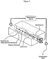
- FIG. 4 depicts a nanochannel constricted at one end proximate to a reservoir and a detector monitoring a signal arising out of a reservoir into which a macromolecule is linearly transported.
- FIG. 5 depicts a constriction connects two nanochannels.
- the detector monitors one or more signals evolved across the constricted nanochannel assembly.
- one end of the macromolecule is first transpported into one end of the nanochannel.
- this may be accomplished by, for example, gradient structures, that assist such delivery; suitable gradient structures are described in U.S. Pat. No. 7,217,562, to Cao, et al. , the entirety of which is incorporated by reference herein.
- Such methods include providing at least two fluid reservoirs and providing an at least partially linearized macromolecule at least a portion of the macromolecule residing in a nanochannel.
- the macromolecule may be linearized by confinement in a suitably-dimensioned nanochannel having an inner diameter of less than about twice the radius of gyration of the linearized macromolecule.
- Suitable nanochannels place the reservoirs in fluid communication with one another.
- Suitable nanochannels as described elsewhere herein, also include a constriction.
- the dimensions of suitable constrictions are described elsewhere herein.
- the methods also include the application of a gradient to the macromolecule.
- the gradient suitably gives rise to at least a portion of the linearized macromolecule being transported within at least a portion of the nanochannel.
- Suitable gradients include an electroosmotic field, an electrophoretic field, capillary flow, a magnetic field, an electric field, a radioactive field, a mechanical force, an electroosmotic force, an electrophoretic force, an electrokinetic force, a temperature gradient, a pressure gradient, a surface property gradient, a capillary flow, or any combination thereof.
- the gradient may suitably by constant or vary, depending on the needs of the user.
- the reservoirs are generally larger in volume than that of the nanochannel segments.
- the reservoirs can be of almost any shape and size.
- a reservoir may be circular, spherical, rectangular, or any combination thereof.
- the size of a reservoir will be dictated by the user's needs and may vary.
- the nanochannels of the disclosed method have a length of greater than about 10 nm, or greater than about 12 nm, or greater than about 14 nm, or greater than about 16nm, or greater than about 18 nm, or greater than about 20 nm, or greater than about 25 nm, or greater than about 30 nm, or greater than about 35 nm, or greater than about 40 nm, or greater than about 45 nm.
- the nanochannels have a length of greater than about 100 nm or even greater than about 500 nm.
- Suitable nanochannels can also be greater than about 1 micron in length, or greater than about 10 microns, or greater than about 100 microns, or greater than about 1 mm, or even greater than about 10 mm in length. In some embodiments, the length of the nanochannel is chosen to exceed about the length of the linearized macromolecule.
- Suitable nanochannels have an effective internal diameter in the range of from about 0.5 nm to about 1000 nm, or in the range of from about 1 nm to about 500 nm, or in the range of from about 5 nm to about 100 nm, or in the range of from about 10 nm to about 15 nm.
- Nanochannel effective inner diameters can also be at least about 15 nm, or at least about 20 nm, or at least about 30 nm, or at least about 40 nm, or at least about 50 nm, or at least about 60 nm, or at least about 70 nm, or at least about 80 nm, or at least about 90 nm, or at least about 100 nm.
- the methods also include the step of reducing the effective internal diameter of the nanochannel either at a location within the nanochannel, at a location proximate to the end of the nanochannel, or both, so as to give rise to a constriction within or adjacent to the nanochannel, the constriction having an internal diameter in fluidic communication with the nanochannel.
- Sample constrictions are shown in FIG. 1b , FIG. 4 , FIG. 5 , and FIG. 6 .
- Suitable nanochannels are capable of maintaining a linearized macromolecule in its linearized form; as discussed elsewhere herein, this is suitably accomplished by using nanochannel segments of suitable dimensions so as to physically constrain the macromolecule to maintain the macromolecule in substantially linear form.
- the reduced internal diameter of the constricted nanochannel is suitably capable of permitting the passage of at least a portion of a linearized macromolecule.
- the internal diameter of the nanochannel is reduced so as to form the constriction by additively depositing one or more materials within, or exterior to, the nanochannel. This is suitably accomplished by sputtering, spraying, physical vapor deposition, chemical vapor deposition, or any combination thereof.
- the additive deposition ceases before the nanochannel is completely occluded. This is depicted in FIGS. 6a and 6b , where the deposition of additive material proximate to one end of a nanochannel is shown, the deposition ceasing before the nanochannel is completely occluded.
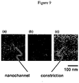
- FIG. 9 Such a nanochannel is also shown in FIG. 9 , in which the reduction in effective inner diameter is seen as the end of the nanochannel ( FIG. 9a ) is reduced by varied deposition ( FIGS. 9b and 9c ) of additive material.
- the additive deposition ceases after the nanochannel is completely occluded.
- the methods include the step of re-opening the sealed nanochannel by removing at least a portion of the deposited additive material. This is suitably accomplished by etching.
- the etching process entails contacting one side of deposited additive material with an first species capable of etching the deposited additive material and contacting the other side of the deposited additive material with a second species capable of retarding the etching activity of the etch species upon contact with the first species.
- the second species is capable of halting the etching activity of the etch species upon contact with the first species. This is depicted in FIG.
- FIG. 7a where sealing material is applied at one end of a nanochannel and then, FIG. 7b , etched away by a strongly basic solution, the etching ceasing, FIG. 7c , when the basic solution etches through the sealing material and is neutralized by the strong acid residing on the opposite side of the sealing material.
- FIG. 7c the conditions in the nanochannel, the relative amounts of the first and second species, and other operating parameters will be adjusted so as to achieve the desired diameter.
- reducing the internal diameter of the nanochannel includes several steps: ( FIG. 8a ) placing a sacrificial material within the nanochannel, ( FIG. 8b ) depositing additive material proximate to the sacrificial material so as to fully occlude the nanochannel, and ( FIG. 8c ) selectively removing at least a portion of the sacrificial material while leaving essentially intact the proximate additive material so as to give rise to a reduced internal diameter of the nanochannel of the dimension of the removed sacrificial material.
- this aspect of the present invention is useful for fabricating voids having a variety of dimensions within nanoscale and larger channels or within other structures.
- DNA and carbon nanotubes are both considered suitable sacrificial materials. Other materials that may be selectively dissolved or etched away will be apparent to those having ordinary skill in the art.
- the present invention also provides methods for linearizing macromolecules so as to constrain the degrees of freedom of the macromolecules from three dimensions to essentially one dimension. These methods include placing a macromolecule in a nanochannel, at least a portion of the nanochannel being capable of physically constraining at least a portion of the macromolecule so as to maintain in linear form that portion of the macromolecule.
- the nanochannels suitably include a constriction. Suitable dimensions for constrictions are described elsewhere herein.
- the methods also include, in some embodiments, applying a gradient to the macromolecule, such that at least a portion of the macromolecule passes, linearly, through the nanochannel constriction.
- Suitable gradients include an electroosmotic field, an electrophoretic field, capillary flow, a magnetic field, an electric field, a radioactive field, a mechanical force, an electroosmotic force, an electrophoretic force, an electrokinetic force, a temperature gradient, a pressure gradient, a surface property gradient, a capillary flow, or any combination thereof.
- microchannels of the disclosed methods suitable place two or more fluid reservoirs in fluid communication with one another.
- Nanochannels suitable include an internal diameter of less than about two times the radius of gyration of the linear conformation of the macromolecule.
- Nanochannels suitably have lengths of at least about 10 nm, of at least about 50 nm, of at least about 100 nm, of at least about 500 nm.
- Suitable inner diameters for nanochannels are in the range of from about 0.5 nm to about 1000 nm, or in the range of from about 5 nm to about 200 nm, or in the range of from about 50 nm to about 100 nm.
- Deposition of filling material was provided by sputtering, CVD, e-beam evaporation with a tilted sample wafer at various angles. This step was used to both reduce the nanochannel openings and create a tapered nozzle at the end of the channels.
- Example 1 A silicon substrate was provided having a plurality of parallel linear channels having a 150 nm trench width and a 150 nm trench height. These channel openings are sputtered at a gas pressure of 5 mTorr according to the general procedures given above. The sputter deposition time was 10-25 minutes to provide a nanochannel array that can either be partially sealed or completely sealed.
- Example 2 This example provides an enclosed nanochannel array using an e-beam deposition technique.
- a substrate can be provided as in Example 1 .
- Silicon dioxide can be deposited by an e-beam (thermo) evaporator (Temescal BJD-1800) onto the substrate.
- the substrate can be placed at various angles incident to the depositing beam from the silicon dioxide source target; the deposition rate can be set to about 3 nm/minute and 150 nm of sealing material can be deposited in about 50 minutes.
- the angle of the incident depositing beam of sealing material can be varied to reduce the channel width and height to less than 150 nm and 150 nm, respectively, and to substantially seal the channels by providing shallow tangential deposition angles.
- Example 3 In this example, a nanochannel array can be contacted with a surface-modifying agent.
- a nanochannel array made according to Example 1 can be submerged in solution to facilitate wetting and reduce non-specific binding.
- the solution can contain polyethelyene glycol silane in toluene at concentrations ranging from 0.1 - 100 mM and remains in contact with the nanochannel array from about 1 hour to about 24 hours. Subsequent washing in ethanol and water is used to remove ungrafted material.
- Example 4 This example describes a sample reservoir with a nanochannel array for a nanofluidic chip.
- a nanochannel array having 100 nm wide, 100 nm deep nanochannels was made according to general procedures of Example 1 .
- the nanochannel array was spin-coated with a photoresist such as AZ-5214E and patterned by photolithography with a photomask using a Karl Suss MA6 Aligner to provide regions on opposite ends of the channel array for preparing the reservoirs.
- the exposed areas were etched using reactive ion etching in a Plasma-Therm 720SLR using a combination of CF 4 and O 2 at a pressure of 5mTorr and RF power of 100W with an etch rate of 20 nm/min to expose the nanochannel ends and to provide a micron-deep reservoir about a millimeter wide on the opposite ends of the channels at the edge of the substrate.
- Example 5 This example describes filling a nanofluidic chip with a fluid containing DNA macromolecules to analyze DNA.
- a cylindrical-shaped plastic sample-delivery tube of 2 mm diameter was placed in fluid communication with one of the reservoirs of the nanochannel array of Example 3 .
- the delivery tube can be connected to an external sample delivery/collection device, which can be in turn connected to a pressure /vaccum generating apparatus.
- the nanochannels are wetted using capillary action with a buffer solution.
- a buffer solution containing stained for example lambda phage macromolecules (lambda DNA) were introduced into the nanochannel array by electric field (at 1-50 V/cm); the solution concentration was 0.05-5 microgram/mL and the lambda DNA was stained at a ratio of 10:1 base pair/dye with TOTO-1 dye (Molecular Probes, Eugene, Oregon).
- This solution of stained DNA was diluted to 0.01-0.05microgram/mL into 0.5xTBE (tris-boroacetate buffer at pH 7.0) containing 0.1M of an anti-oxidant and 0.1% of a linear polyacrylamide used as an anti-sticking agent.
- Example 6 This example describes the fabrication of a nanozzle at end of nanochannel using acid etching. Fabrication of the nanozzle device begins with a completed silicon nanochannel having enclosed nanochannels as provided in Example 1 . Creation of the nanopore proceeds by sputter coating a thin layer of chromium over the exposed end of the channel. Sputter coating using a Temescal system can be controlled with sub-nm precision with deposition amounts of 5 - 200 nm at a rate of 0.01 - 1 nm/sec or until the end of the nanochannel is completely covered with chromium. A wet-etch process can then be employed to open a sub-10 nm pore in the chromium.
- a dilute chromium etchant such as Cr -7 can be flowed into the channel using capillary forces or other forms of pumping. Dilution can range from 1X to 10,000X. Because Cr -7 is a highly selective acid etchant, it will preferentially react with the chromium at the end of the channel rather than the silicon channels themselves. To stop the etch once a pore has opened, the area outside the channel will be filled with a highly concentrated base solution (such as sodium hydroxide) that will rapidly neutralize the weak acid upon breakthrough. After subsequent washing of the device, the result will be a nanoscale nozzle at the end of a nanochannel.
- a highly concentrated base solution such as sodium hydroxide
- Example 7 This example describes how to fabricate a nanonozzle chip using a sacrificial macromolecule.
- a nanofluidic chip with input/output fluid reservoirs connected by nanochannels is used to linearize double strand DNA ( FIG. 8a ).
- long fragments of DNA approximately 1-10 Mbp in length, uniformly stained with YOYO-1 is preferable.
- the concentration of the DNA should be around 0.5 micrograms/mL, with the dye stained to a ratio of 10:1 base pair/dye.
- the buffer solution is composed of 0.5x TBE (tris-boroacetate buffer at pH 7.0) containing 0.1M of an anti-oxidant and 0.1% of a linear polyacrylamide used as an anti-sticking agent.
- the solution of sacrificial DNA molecules are flowed into the nanochannels of the chip, where they exit the nanochannels at the outlet reservoir.
- the exit of the DNA molecules is observed in real time, and their movement controlled by applying an electric field across the reservoirs (1-50 V/cm).
- an electric field across the reservoirs (1-50 V/cm).
- a desired DNA fragment's position can be suspended having only partially exited the nanochannel.
- the nanochannel chip is then dried at 50°C in vacuum environment removing any residual buffer solution, so that the DNA fragment of interest remains partially inside the nanochannel. Interaction between the nanochannel surface and the DNA fragment, such as through van der Waals bonding, maintains the fragment's position in the channel during the drying process.
- a material such as silicon dioxide is deposited over the surface of the chip ( FIG. 8b ) such that the entrance to the nanochannel becomes blocked, and the DNA fragment enclosed.
- the rate of material deposition and the temperature of the deposition must be carefully chosen such that the DNA fragment is not damaged during this process.
- Evaporating material at 0.2 A/s or less on a sample kept at -160°C using a cooling stage has been shown to protect small organic molecules from damage (Austin 2003).
- the stage is rotated and tilted during the evaporation process. To completely close a nanochannel of 80 nm in diameter, approximately 200 nm of silicon dioxide material should be evaporated.
- Example 8 Operation of a Device - Electrical measurement for Sequenceing single-stranded nucleic acid: A voltage bias is applied across a nanochannel device having a constriction (either nanogate or nanozzle) approximately 1.5 nm inner diameter placed at one end of the nanochannel, the nanochannel being about 200 microns in length, for a single strand nucleic acid for sequencing using electrodes (can be copper, silver, titanium, platinum, gold, or aluminum) contacting reservoirs at each end of the nanochannel, the reservoirs having dimensions of about 5 - 100 microns in diameter and 1-2 microns deep. The electrodes are deposited into the reservoirs and lead lines leading to outside the fluidic region for connection to a current monitor.
- electrodes can be copper, silver, titanium, platinum, gold, or aluminum
- a voltage range of 100 mV - 100V can be used.
- Biological buffer TE, TBE, TAE
- a pressure differential aids in wetting the nanofluidic device using a suitable fluidic delivery pump or syringe.
- a nucleic acid sample e.g., 100 base sDNA and up, at least 1000 bases, or 10000 bases, or 100000 bases, or 1 million, or even 10 million, or even 100 million, up to chromosomal length
- buffer solution (1 nanoliter up to about 100 microliters) is delivered to one or both of the reservoirs.
- a gradient is applied to aid in the transport of one or more polynucleic acid molecules into the nanochannel in into the constriction.
- a field is applied, specifically in this example, a controlled voltage gradient to apply a current from one reservoir, throght the nanochannel, through the constriction with the polynulceic acid residing within the constriction, and into the second reservoir.
- the electrical current flowing through this system is detected and amplified using an Axopatch 200B (Molecular Devices) patch clamp amplifier.
- Typical measured currents range from about 100 fA to about 1 uA with fluctuations approximatley hundreds of picoamps as the DNA moves through the constriction. Labels attached to the single strand DNA can produce additional current fluctuations of magnitude smaller than that created by the DNA itself.
- typical translocation speed is such that the measurement system can register a minimum of 1 measurement per base.
- the maximum translocation speed is 100 kB/sec, assuming 50% stretching of the DNA molecule in the nanochannel. This gives rise to a translocation speed of the DNA through the construction to be about 0.015 nm/microsec.
- the measure current differences are measured and correlated to a seet of calibration standards to give rise to the sequence of the DNA sample.
Abstract
Description
- This application claims the benefit of
U.S. Provisional Application No. 60/831,772, filed July 19, 2006 U.S. Provisional Application No. 60/908,582, filed on March 28, 2007 U.S. Provisional Application No. 60/908,584, filed March 28, 2007 - The present invention pertains to the field of nanoscale devices. The present invention also pertains to the field of macromolecular sequencing, particularly the field of DNA sequencing and characterization.
- Various scientific and patent publications are referred to herein. Each is incorporated by reference in its entirety.
- Biomolecules such as DNA or RNA are long molecules composed of nucleotides, the sequence of which is directly related to the genomic and post-genomic gene expression information of an organism. In most cases, the mutation or rearrangement of the nucleotide sequences during an individual's life span can lead to disease states such as genetic abnormalities or cell malignancy. In other cases, the small amount of sequence differences among each individual reflects the diversity of the genetic makeup of the population. Because of these differences in genetic sequence, certain individuals respond differently to environmental stimuli and signals, including drug treatments. For example, some patients experience positive response to certain compounds while others experience no effects or even adverse side effects.
- The fields of population genomics, medical genomics and pharmacogenomics studying genetic diversity and medical pharmacological implications require extensive sequencing coverage and large sample numbers. The sequencing knowledge generated would be especially valuable for the health care and pharmaceutical industry. Cancer genomics and diagnostics study genomic instability events leading to tumorigenesis. All these fields would benefit from technologies enabling fast determination of the linear sequence of biopolymer molecules such as nucleic acids, or epigenetic biomarkers such as methylation patterns along the biopolymers. There is a long felt need to use very little amount of sample, even as little as a single cell. This would greatly advance the ability to monitor the cellular state and understand the genesis and progress of diseases such as the malignant stage of a cancer cell.
- Most genome or epigenome analysis technologies remain too expensive for general analysis of large genomic regions for a large population. In order to achieve the goal of reducing the genomic analysis cost by at least four orders of magnitude, the so-called "$1000 genome" milestone, new technologies for molecular analysis methods are needed. See "The Quest for the $1,000 Human Genome," by Nicholas Wade, The New York Times, July 18, 2006.
- One technology developed for fast sequencing involves the use of a nanoscale pore through which DNA is threaded. Historically, the "nanopore" concept used a biological molecular device to produce ionic current signatures when RNA and DNA strands are driven through the pore by an applied voltage. Biological systems, however, are sensitive to pH, temperature and electric fields. Further, biological molecules are not readily integrated with the semiconductor processes required for sensitive on-chip electronics.
- Many efforts have been since focused on designing and fabricating artificial nanopores in solid state materials. These methods, however, which are capable of producing only pores in membranes are not capable of producing longer channels needed to achieve true single-molecule sequencing of long biological polymers such as DNA or RNA.
- Accordingly, there is a need in the field for devices capable of yielding sequence and other information for long biological polymers such as DNA or RNA.
- In meeting the described challenges, in a first aspect the present invention provides methods for characterizing one or more features of a macromolecule, comprising linearizing a macromolecule residing at least in part within a nanochannel, at least a portion of the nanochannel being capable of physically constraining at least a portion of the macromolecule so as to maintain in linear form that portion of the macromolecule, and the nanochannel comprising at least one constriction; transporting at least a portion of the macromolecule within at least a portion of the nanochannel such that at least a portion of the macromolecule passes through the constriction; monitoring at least one signal arising in connection with the macromolecule passing through the constriction; and correlating the at least one signal to one or more features of the macromolecule.
- In a second aspect, the present invention provides devices for analyzing a linearized macromolecule, comprising two or more fluid reservoirs; and a nanochannel comprising a constriction, the nanochannel placing the at least two fluid reservoirs in fluid communication with one another.
- Further provided are methods for transporting a macromolecule, comprising providing at least two fluid reservoirs; providing an at least partially linearized macromolecule, at least a portion of the macromolecule residing in a nanochannel, the nanochannel placing the at least two reservoirs in fluid communication with one another, the nanochannel comprising a constriction; and applying a gradient to the macromolecule, the gradient giving rise to at least a portion of the linearized macromolecule being transported within at least a portion of the nanochannel.
- Additionally provided are methods for fabricating a constricted nanochannel, comprising providing a nanochannel; the nanochannel having an internal diameter in the range of from about 0.5 nm to about 1000 nm, and the nanochannel having a length of at least about 10 nm; reducing the internal diameter of the nanochannel either at a location within the nanochannel, at a location proximate to the end of the nanochannel, or both, so as to give rise to a constriction within or adjacent to the nanochannel, the constriction having an internal diameter in fluidic communication with the nanochannel, the nanochannel being capable of maintaining a linearized macromolecule in its linearized form, and the reduced internal diameter being capable of permitting the passage of at least a portion of a linearized macromolecule.
- Also disclosed are methods for linearizing a macromolecule, comprising placing a macromolecule in a nanochannel, at least a portion of the nanochannel being capable of physically constraining at least a portion of the macromolecule so as to maintain in linear form that portion of the macromolecule.
- The general description and the following detailed description are exemplary and explanatory only and are not restrictive of the invention, as defined in the appended claims. Other aspects of the present invention will be apparent to those skilled in the art in view of the detailed description of the invention as provided herein.
- The summary, as well as the following detailed description, is further understood when read in conjunction with the appended drawings. For the purpose of illustrating the invention, there are shown in the drawings exemplary embodiments of the invention; however, the invention is not limited to the specific methods, compositions, and devices disclosed. In addition, the drawings are not necessarily drawn to scale. In the drawings:
-
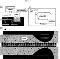
FIG. 1a is a schematic view of a DNA sequencer showing linearized double-stranded DNA passing through a nanochannel into an outlet reservoir, where a measurement device detects physical, chemical, electrical, or other changes in the outlet reservoir or within the nanochannel related to the passage of the DNA; -
FIG. 1b depicts a DNA molecule flowing through a nanonozzle constriction at the end of a nanochannel; -
FIG. 1c depicts the data evolved from the passage of the DNA through the constricted nanochannel; -
FIG. 2a is a schematic view of a DNA sequencer showing linearized single-stranded DNA passing through a nanochannel into an outlet reservoir, where a measurement device detects any physical, chemical, electrical, or other changes in the outlet reservoir or within the nanochannel related to the passage of the DNA; -
FIG. 2b depicts single-stranded DNA molecule flowing through a nanonozzle constriction at the end of a nanochannel; -
FIG. 2c depicts the data evolved as individual nucleotides of the single-stranded DNA pass through the constriction of the nanochannel; -
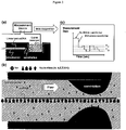
FIG. 3a is a schematic view of a DNA sequencer showing linearized, methylated double-stranded DNA passing through a nanochannel into an outlet reservoir, where a measurement device detects any physical, chemical, electrical, or other changes in the outlet reservoir or within the nanochannel related to the passage of the DNA; -
FIG. 3b depicts the methylated double-stranded DNA molecule flowing through a nanonozzle constriction at the end of a nanochannel; -
FIG. 3c depicts the data evolved as individual nucleotides of the methylated double-stranded DNA pass through the constriction of the nanochannel; -
FIG. 4 depicts an representative embodiment of an enclosed nanochannel in communication with a reservoir, the nanochannel having a constriction of cross-sectional area smaller than remainder of nanochannel, and macromolecules being linearized within the nanochannel and features of interest on the molecule being detected as they pass through the constriction; -
FIG. 5 depicts an enclosed nanochannel in communication with a second nanochannel via a constriction of cross-sectional area smaller than both nanochannels, macromolecules are linearized within the nanochannel and features of interest on the molecule are detected as they pass through the constriction; -
FIG. 6a depicts the preparation of a constriction at the end of a nanochannel by additive material deposition, andFIG 6b is a scanning electron micrograph of an embodiment of such a constriction at the end of a nanochannel; -
FIG. 7 depicts a representative fabrication of a constriction at the end of a nanochannel by (FIG. 7a ) deposition of material at the end of the nanochannel resulting in complete sealing of the channel; (FIG. 7b ) self-terminating opening of the constriction using an acid etchant terminated by exposure to a neutralizing strong base; and (FIG. 7c ) the final nanonozzle device after the etchant and neutralizer are removed; -
FIG. 8 depicts an representative fabrication of a constriction at the end of a nanochannel using sacrificial material: (FIG. 8a ) a sacrificial macromolecule is placed into the nanochannel and allowed to partially exit into the reservoir; (FIG. 8b ) the fluid is removed and material is deposited around the sacrificial molecule; and (FIG. 8c ) the sacrificial molecule is removed leaving a constriction at the end of the nanochannel; and -
FIG. 9 presents a series of three scanning electron micrographs that describes the gradual reduction in size of a channel opening using additive deposition of material: (FIG. 9a ) additive deposition of silicon oxide on an open nanochannel of initial width and height of about 150 nm leads to an enclosed nanochannel of about 50 nm diameter, (FIG. 9b ) variation of the deposition of parameters leads to smaller enclosed channels, and (FIG. 9c ) by extension, a sub-10 nm opening can be created. - As used herein, the term "substantially linear" means that the conformation of at least a portion of a long molecule, such as, but not limited to, a polynucleic acid comprising 200 nucleic acids linked together, does not loop back on itself or does not containing any sharp bends or curves greater than about 360 degrees.
- As used herein, the term "nanochannel" means a conduit, channel, pipe, duct, or other similar structure having at least one nanoscale dimension.
- The present invention may be understood more readily by reference to the following detailed description taken in connection with the accompanying figures and examples, which form a part of this disclosure. It is to be understood that this invention is not limited to the specific devices, methods, applications, conditions or parameters described and/or shown herein, and that the terminology used herein is for the purpose of describing particular embodiments by way of example only and is not intended to be limiting of the claimed invention. Also, as used in the specification including the appended claims, the singular forms "a," "an," and "the" include the plural, and reference to a particular numerical value includes at least that particular value, unless the context clearly dictates otherwise. The term "plurality", as used herein, means more than one. When a range of values is expressed, another embodiment includes from the one particular value and/or to the other particular value. Similarly, when values are expressed as approximations, by use of the antecedent " about," it will be understood that the particular value forms another embodiment. All ranges are inclusive and combinable.
- It is to be appreciated that certain features of the invention which are, for clarity, described herein in the context of separate embodiments, may also be provided in combination in a single embodiment. Conversely, various features of the invention that are, for brevity, described in the context of a single embodiment, may also be provided separately or in any subcombination. Further, reference to values stated in ranges include each and every value within that range.
- In one aspect, the present invention provides methods for characterizing one or more features of a macromolecule. These methods include linearizing a macromolecule residing at least in part within a nanochannel, at least a portion of the nanochannel being capable of physically constraining at least a portion of the macromolecule so as to maintain in linear form that portion of the macromolecule.
- Suitable nanochannels have a diameter of less than about twice the radius of gyration of the macromolecule in its extended form. A nanochannel of such dimension is known to begin to exert entropic confinement of the freely extended, fluctuating macromolecule coils so as to extend and elongate the coils. Suitable nanochannels can be prepared according to the methods described in Nanochannel Arrays And Their Preparation And Use For High-Throughput Macromolecular Analysis,
U.S. Pat. Application No. 10/484, 293, filed January 20, 2004 - Suitable nanochannels include at least one constriction. Such constrictions function to locally reduce the effective inner diameter of the nanochannel. Constrictions can be sized so as to permit the passage of linearized macromolecules.
- The methods also include the step of transporting at least a portion of the macromolecule within at least a portion of the nanochannel such that at least a portion of the macromolecule passes through the constriction. This is shown in, for example,
FIGS. 1b ,2b , and3b , in which DNA is shown passing through a nanochannel constriction. Constrictions can be made, for example by depositing material at the end of a nanochannel to seal off the nanochannel, and then etching away a portion of the deposited material until a pore much narrower than the nanochannel is produced. This is further illustrated inFIGS. 6 to 9 . - Where a comparatively long macromolecule is to be analyzed, the end of the macromolecule is delivered into one end of the nanochannel. This is accomplished by, for example, gradient structures, that assist such delivery into a nanochannel; suitable gradient structures are described in
U.S. Pat. No. 7,217,562, to Cao, et al . - The methods also include monitoring at least one signal arising in connection with the macromolecule passing through the constriction; and correlating the at least one signal to one or more features of the macromolecule. This is depicted in
FIGS. 1a ,2a , and3a , which depict a schematic of monitoring a signal arising in connection with the passage of a macromolecule through a constriction in a nanochannel. Suitable signals include, for example, electric charge signals, optical signals, electromagnetic signals, magnetic signals, or any combination thereof. Electrical signals can be monitored using, for example, any of a variety of commercially available current meters and amplifiers. For example, suitable signal monitoring equipment is capable of applying a constant voltage in the range of from about a nanovolt, or a microvolt, or a millivolt, or even a volt or more across electrodes in contact with liquid within the reservoirs and nanochannel segment. Suitable monitoring equipment is also capable of measuring current between the electrodes many times persecond. Suitable equipment will have a bandwidth of at least about 100 Hertz ("Hz", cycles per second), or about 1 kilohertz ("kHz"), or about 10 kHz, or about 100 kHz, or about 1 megahertz ("MHz"), or even about 10 megahertz. Accordingly, current can be made once measurements are variations on the order of the nanosecond, or the microsecond, or even on the millisecond scale. Current amplitude can be from pico seconds ...Translocation speed of a sDNA can be around 40 bases per microsecond through a typical "patch clamp amplifier". Best machine today can sample once every microseconds. Axopatch 200B, Molecular Devices (www.moleculardevices.com), having a bandwidth of 100 KHz, is capable of 100,000 current measurements per second, or equivalent to 10 microseconds per current measurement of a change in the current between the electrodes connected to the two waste reservoirs. - Macromolecules suitable for the present method include polynucleotides, polynucleosides, natural and synthetic polymers, natural and synthetic copolymers, dendrimers, surfactants, lipids, natural and synthetic carbohydrates, natural and synthetic polypeptides, natural and synthetic proteins, or any combination thereof. DNA is considered a particularly suitable macromolecule that can be analyzed according to the methods as discussed elsewhere herein.
- A macromolecule analyzed according to the methods as provided herein typically resides within a fluid. Suitable fluids include water, buffers, cell media, and the like. Suitable fluids can also be electrolytic, acidic, or basic.
- Transporting the macromolecule is accomplished by exposing the macromolecule to a gradient, the gradient suitably applied along the flow direction of a suitable nanochannel. Suitable gradients include an electroosmotic field, an electrophoretic field, capillary flow, a magnetic field, an electric field, a radioactive field, a mechanical force, an electroosmotic force, an electrophoretic force, an electrokinetic force, a temperature gradient, a pressure gradient, a surface property gradient, a gradient of hydrophobicity, a capillary flow, or any combination thereof. An electric field is a particularly suitable gradient.
- The gradient may be temporally constant, spatially constant, or any combination thereof. The gradient may also vary in space and time as needed. In some embodiments, varying the gradient enables the transportation of the macromolecule in both forward and reverse directions. In some embodiments, varying the gradient permits the same portion of the macromolecule to be passed through the constriction multiple times.
- Varying the gradient also enables the user to advance the macromolecule quickly through the constriction until a region of particular interest on the macromolecule is reached, in a manner analogous to fast-forwarding a cassette tape to a desired selection. Once the region of interest is reached, the gradient may be varied so as to pass the region of interest through the constriction at a lower speed. The gradient may also be reversed to effect a reverse movement of the macromolecule through the restriction. This would be analogous to rewinding the cassette tape to a desired position. Accordingly, "play", "fast forward" , "rewind", "pause" and "stop" functions can arise by controlling the magnitude and polarity of the gradient between the reservoirs.
- Suitable signals that can be detected include a visual signal, an infrared signal, an ultraviolet signal, a radioactive signal, a magnetic signal, an electrical signal, an electromagnetic signal, or any combination thereof. Electrical signals are considered preferable for the reason that they are easily monitored, but other signals may be effectively monitored.
- The macromolecule may include one or more labels; suitable labels include electron spin resonance molecule, a fluorescent molecule, a chemilumenescent molecule, an isotope, a radiosotope, an enzyme substrate, a biotin molecule, an avidin molecule, an electrical charge-transferring molecule, a semiconductor nanocrystal, a semiconductor nanoparticle, a colloid gold nanocrystal, a ligand, a microbead, a magnetic bead, a paramagnetic particle, a quantum dot, a chromogenic substrate, an affinity molecule, a protein, a peptide, a nucleic acid, a carbohydrate, an antigen, a hapten, an antibody, an antibody fragment, a lipid, a polymer, an electrically charged particle, a modified nucleotide, a chemical functional group, a chemical moiety, or any combination thereof. In some embodiments, the label is a chemical moiety such as a methyl group. This is shown in non-limiting fashion at
FIG. 3b , which depicts a DNA strand labeled with several methyl groups and the detection of those methyl groups as indicative of the presence of one or more particular features of the labeled DNA. - Signals are, in some embodiments, inherently emitted by the macromolecule. Such inherently emitted signals include magnetic signals or radioactive signals, where the macromolecule or portions of the macromolecule are magnetic or radioactive. Where the signal is inherently emitted by the macromolecule, it may not also be necessary to illuminate the macromolecule so as to elicit a detectable signal.
- In other embodiments, the signal is generated by illuminating the molecule. Illumination includes exposing at least a portion of the macromolecule to visible light, ultraviolet light, infrared light, x-rays, gamma rays, electromagnetic radiation, radio waves, radioactive particles, or any combination thereof. Suitable illumination devices include coherent and incoherent sources of light which can illuminate, excite, or even scatter from the macromolecule. UV, VIS, IR light sources can be used, such as lasers and other light surfaces.
- Features of macromolecules detected by the disclosed methods include the size of the macromolecule, the molecular composition of the macromolecule, the molecular sequence of the macromolecule, an electrical property of one or more molecules of the macromolecule, a chemical property of one or more molecules of the macromolecule, a radioactive property of one or more molecules of the macromolecule, a magnetic property of one or more molecules of the macromolecule, or any combination thereof.
- As discussed elsewhere herein, macromolecules are, in some embodiments, labeled. Accordingly, a feature of such macromolecule is the location of one or more labels of the macromolecule.
- The molecular composition of a molecule is also characterized by the instant methods. The molecular composition includes the position of one or more molecules of the macromolecule, DNA polymorphisms, DNA copy number polymorphisms, amplifications within DNA, deletions within DNA, translocations within DNA, inversions of particular loci within DNA, the location of a methyl group within the macromolecule, or any combination thereof. Polymorphisms are, in some embodiments, detected by observing the presence of a labeled probe that is complementary only to that polymorphism.
- The detection of binding sites between a drug and the macromolecule, macromolecule-drug complexes, DNA repairing sites, DNA binding sites, DNA cleaving sites, SiRNA binding sites, anti-sense binding sites, transcription factor binding sites, regulatory factor binding sites, restriction enzyme binding sites, restriction enzyme cleaving sites, or any combination thereof are all included within the present invention.
- As discussed elsewhere herein, such features are determined by interrogating the macromolecule for the presence of one or more probes complementary to the features of interest. The methods are shown schematically in
FIGS. 1c 2c, and3c, each of which depicts the monitoring of a signal arising in connection with the passage of the macromolecule through the nanochannel constriction. In some embodiments, two or more probes are used to determine two or more features of a given macromolecule. - Certain embodiments of the device include a plurality of nanochannels. Such arrays of nanochannels are useful in efficiently characterizing multiple features of a single macromolecule or multiple features of multiple macromolecules. It will be apparent to one having ordinary skill in the art that labels complementary to certain features can be chosen and then applied to a given macromolecule that is then characterized to determine whether such features are present on that given macromolecule.
- Also disclosed are devices for analyzing a linearized macromolecule. Suitable devices include two or more fluid reservoirs and a nanochannel comprising a constriction and the nanochannel placing the at least two fluid reservoirs in fluid communication with one another. As described elsewhere herein, suitable nanochannels are capable of physically constraining at least a portion of macromolecule so as to maintain that portion in linear form. This is set forth in further detail in
U.S. Application No. 60/831,772, filed July 19, 2006 U.S. Application No. 60/908,582, filed on March 28, 2007 U.S. Application No. 60/908,584, filed March 28, 2007 - The constriction suitably resides at one end of the nanochannel. In some embodiments, however, the constriction resides within the nanochannel. The ultimate location of the constriction will depend on the user's needs. Constrictions inside a nanochannel can be made as follows: using a sacrificial material as a filler as described further herein (see, e.g., Example 7 discussed further below).
- Suitable nanochannels have a length in the range of at least about 10 nm, or at least about 15 nm, or at least about 20 nm, at least about 30 nm, at least about 50 nm, or even at least about 100 nm, at least about 500 nm, or at least about 1000 nm. In some embodiments, the nanochannel comprises a length at least equal to about the length of the linearized macromolecule.
- Suitable nanochannels also have an effective inner diameter in the range of from about 0.5 nm to about 1000 nm, or in the range of from about 10 nm to about 500 nm, or in the range of from about 100 nm to about 300 nm, or in the range of from about 150 nm to about 250 nm. Nanochannel effective inner diameters can also be at least about 15 nm, or at least about 20 nm, or at least about 30 nm, or at least about 40 nm, or at least about 50 nm, or at least about 60 nm, or at least about 70 nm, or at least about 80 nm, or at least about 90 nm, or at least about 100 nm. As discussed, the nanochannel comprises an effective inner diameter capable of maintaining the macromolecule in linearized form.
- The terms "effective inner diameter" and "inner diameter" are used interchangeably unless indicated otherwise. The term "effective inner diameter" refers not only to nanochannels having a circular cross-sectional area, but also to nanochannels having non-circularly shaped cross sectional areas. For example, the "effective inner diameter" can be determined by assuming the nanochannel has a circular cross section, and forcing the actual cross sectional area of the nanochannel to be effectively calculated in terms of the area of a circle having an effective inner diameter: Cross Sectional Area of Nanochannel = pi x (effective inner diameter/ 2)2. Accordingly, the effective inner diameter of a nanochannel can be determined as:

- Constrictions suitably have an effective inner diameter or effective dimension permitting molecular transport in the range of from about 0.5 nm to about 100 nm; or in the range of from about 1 to about 80 nm, or in the range of from about 5 to about 50 nm, or in the range of from about 8 nm to about 30 nm, or in the range of from about 10 nm to about 15 nm. Suitable constrictions have an effective inner diameter capable of maintaining a linearized macromolecule passing across the constriction in linearized form. The effective inner diameter or dimension can be controlled by controlling the etching conditions, or by controlling the size of the sacrificial material within the constriction region.
- The disclosed devices also include a gradient, such gradients suitably existing along at least a portion of the nanochannel. Suitable gradients include an electroosmotic field, an electrophoretic field, capillary flow, a magnetic field, an electric field, a radioactive field, a mechanical force, an electroosmotic force, an electrophoretic force, an electrokinetic force, a temperature gradient, a pressure gradient, a surface property gradient, a capillary flow, or any combination thereof.
- In some embodiments, the gradient is capable of linearizing at least a portion of a macromolecule residing within at least a portion of the nanochannel. In preferred embodiments, however, the gradient is capable of transporting at least a portion of a macromolecule located within the nanochannel along at least a portion of the nanochannel.
- The devices suitably include a gradient generator capable of supplying the described gradient. Suitable generators include a voltage source, a magnet, an acoustic source, a pressure source, or any combination thereof.
- The gradient generator is suitably capable of applying a constant gradient. The gradient generator is also, in some embodiments, capable of applying a variable gradient. The examples set forth elsewhere herein provide additional detail. It will be apparent to one having ordinary skill in the art that the intensity and variability of the gradient will be chosen according to the user's needs.
- The two or more fluid reservoirs of the device comprise the same fluid in some embodiments. In other embodiments, the two or more fluid reservoirs comprise different fluids. In some embodiments, the different fluids may be used to themselves provide the gradient used to transport the macromolecule within the nanochannel - fluids of differing ionic strength or other property may be chosen to provide such a gradient. Suitable fluids include buffers, acids, bases, electrolytes, cell media, surfactants, and the like.
- The devices also include a detector capable of detecting a signal arising from at least a portion of the linearized macromolecule passing through the constriction. Suitable detectors include a charge coupled device (CCD) detection system, a complementary metal-oxide semiconductor (CMOS) detection system, a photodiode detection system, a photo-multiplying tube detection system, a scintillation detection system, a photon counting detection system, an electron spin resonance detection system, a fluorescent detection system, a photon detection system, an electrical detection system, a photographic film detection system, a chemiluminescent detection system, an enzyme detection system, an atomic force microscopy (AFM) detection system, a scanning tunneling microscopy (STM) detection system, a scanning electron microscopy (SEM) detection system, an optical detection system, a nuclear magnetic resonance (NMR) detection system, a near field detection system, a total internal reflection (TIRF) detection system, a patch clamp detection system, an electrical current detection system, an electrical amplification detection system, a resistance measurement system, a capacitive detection system, and the like.
- Suitable detectors are capable of monitoring one or more locations within one or more of the fluid reservoirs, or, in other embodiments, are capable of monitoring a location within the nanochannel, or even a location proximate to an end of the nanochannel. It will be apparent to the user that employing one or more detectors capable of detecting different signals at different locations would enable characterization of multiple features of a given macromolecule.
- In some embodiments, the devices include an illuminator. Illuminators suitable include a laser, a source of visible light, a source of radioactive particles, a magnet, a source of ultraviolet light, a source of infrared light, or any combination thereof. The illuminator is used, in some embodiments, to excite a portion of the macromolecule within the nanochannel. As a non-limiting example, a source of light of a certain wavelength is used to excite fluorescent labels residing at certain, specific locations on the macromolecule so as to elicit the presence of such labels.
- The devices also suitably include a data processor. In some embodiments, the devices includea data recorder. Such processors are used to manipulate and correlate large data sets.
- One embodiment of the disclosed devices is shown in
FIG. 4 , which depicts a nanochannel constricted at one end proximate to a reservoir and a detector monitoring a signal arising out of a reservoir into which a macromolecule is linearly transported. Another embodiment is shown inFIG. 5 , in which a constriction connects two nanochannels. InFIG. 5 , it is seen that the detector monitors one or more signals evolved across the constricted nanochannel assembly. - As discussed elsewhere herein, where a comparatively long macromolecule is to be analyzed, one end of the macromolecule is first transpported into one end of the nanochannel. As discussed, this may be accomplished by, for example, gradient structures, that assist such delivery; suitable gradient structures are described in
U.S. Pat. No. 7,217,562, to Cao, et al. , the entirety of which is incorporated by reference herein. - Also disclosed are methods for transporting a macromolecule. Such methods include providing at least two fluid reservoirs and providing an at least partially linearized macromolecule at least a portion of the macromolecule residing in a nanochannel. As discussed elsewhere herein, the macromolecule may be linearized by confinement in a suitably-dimensioned nanochannel having an inner diameter of less than about twice the radius of gyration of the linearized macromolecule.
- Suitable nanochannels place the reservoirs in fluid communication with one another. Suitable nanochannels, as described elsewhere herein, also include a constriction. The dimensions of suitable constrictions are described elsewhere herein.
- The methods also include the application of a gradient to the macromolecule. The gradient suitably gives rise to at least a portion of the linearized macromolecule being transported within at least a portion of the nanochannel. Suitable gradients include an electroosmotic field, an electrophoretic field, capillary flow, a magnetic field, an electric field, a radioactive field, a mechanical force, an electroosmotic force, an electrophoretic force, an electrokinetic force, a temperature gradient, a pressure gradient, a surface property gradient, a capillary flow, or any combination thereof. The gradient may suitably by constant or vary, depending on the needs of the user.
- The reservoirs are generally larger in volume than that of the nanochannel segments. The reservoirs can be of almost any shape and size. For example, a reservoir may be circular, spherical, rectangular, or any combination thereof. The size of a reservoir will be dictated by the user's needs and may vary.
- The nanochannels of the disclosed method have a length of greater than about 10 nm, or greater than about 12 nm, or greater than about 14 nm, or greater than about 16nm, or greater than about 18 nm, or greater than about 20 nm, or greater than about 25 nm, or greater than about 30 nm, or greater than about 35 nm, or greater than about 40 nm, or greater than about 45 nm. In some embodiments, the nanochannels have a length of greater than about 100 nm or even greater than about 500 nm. Suitable nanochannels can also be greater than about 1 micron in length, or greater than about 10 microns, or greater than about 100 microns, or greater than about 1 mm, or even greater than about 10 mm in length. In some embodiments, the length of the nanochannel is chosen to exceed about the length of the linearized macromolecule.
- Further disclosed are methods for fabricating constricted nanochannels. These methods first include providing a nanochannel. Suitable nanochannels have an effective internal diameter in the range of from about 0.5 nm to about 1000 nm, or in the range of from about 1 nm to about 500 nm, or in the range of from about 5 nm to about 100 nm, or in the range of from about 10 nm to about 15 nm. Nanochannel effective inner diameters can also be at least about 15 nm, or at least about 20 nm, or at least about 30 nm, or at least about 40 nm, or at least about 50 nm, or at least about 60 nm, or at least about 70 nm, or at least about 80 nm, or at least about 90 nm, or at least about 100 nm.
- The methods also include the step of reducing the effective internal diameter of the nanochannel either at a location within the nanochannel, at a location proximate to the end of the nanochannel, or both, so as to give rise to a constriction within or adjacent to the nanochannel, the constriction having an internal diameter in fluidic communication with the nanochannel. Sample constrictions are shown in
FIG. 1b ,FIG. 4 ,FIG. 5 , andFIG. 6 . Suitable nanochannels are capable of maintaining a linearized macromolecule in its linearized form; as discussed elsewhere herein, this is suitably accomplished by using nanochannel segments of suitable dimensions so as to physically constrain the macromolecule to maintain the macromolecule in substantially linear form. The reduced internal diameter of the constricted nanochannel is suitably capable of permitting the passage of at least a portion of a linearized macromolecule. - In one embodiment, the internal diameter of the nanochannel is reduced so as to form the constriction by additively depositing one or more materials within, or exterior to, the nanochannel. This is suitably accomplished by sputtering, spraying, physical vapor deposition, chemical vapor deposition, or any combination thereof. In some embodiments, the additive deposition ceases before the nanochannel is completely occluded. This is depicted in
FIGS. 6a and 6b , where the deposition of additive material proximate to one end of a nanochannel is shown, the deposition ceasing before the nanochannel is completely occluded. Such a nanochannel is also shown inFIG. 9 , in which the reduction in effective inner diameter is seen as the end of the nanochannel (FIG. 9a ) is reduced by varied deposition (FIGS. 9b and 9c ) of additive material. - In other embodiments of the invention, the additive deposition ceases after the nanochannel is completely occluded. In these embodiments, the methods include the step of re-opening the sealed nanochannel by removing at least a portion of the deposited additive material. This is suitably accomplished by etching. The etching process entails contacting one side of deposited additive material with an first species capable of etching the deposited additive material and contacting the other side of the deposited additive material with a second species capable of retarding the etching activity of the etch species upon contact with the first species. In some embodiments, the second species is capable of halting the etching activity of the etch species upon contact with the first species. This is depicted in
FIG. 7a , where sealing material is applied at one end of a nanochannel and then,FIG. 7b , etched away by a strongly basic solution, the etching ceasing,FIG. 7c , when the basic solution etches through the sealing material and is neutralized by the strong acid residing on the opposite side of the sealing material. As will be apparent to those having ordinary skill in the art, the conditions in the nanochannel, the relative amounts of the first and second species, and other operating parameters will be adjusted so as to achieve the desired diameter. - In still other embodiments, reducing the internal diameter of the nanochannel includes several steps: (
FIG. 8a ) placing a sacrificial material within the nanochannel, (FIG. 8b ) depositing additive material proximate to the sacrificial material so as to fully occlude the nanochannel, and (FIG. 8c ) selectively removing at least a portion of the sacrificial material while leaving essentially intact the proximate additive material so as to give rise to a reduced internal diameter of the nanochannel of the dimension of the removed sacrificial material. It will be apparent to those having ordinary skill in the art that this aspect of the present invention is useful for fabricating voids having a variety of dimensions within nanoscale and larger channels or within other structures. DNA and carbon nanotubes are both considered suitable sacrificial materials. Other materials that may be selectively dissolved or etched away will be apparent to those having ordinary skill in the art. - The present invention also provides methods for linearizing macromolecules so as to constrain the degrees of freedom of the macromolecules from three dimensions to essentially one dimension. These methods include placing a macromolecule in a nanochannel, at least a portion of the nanochannel being capable of physically constraining at least a portion of the macromolecule so as to maintain in linear form that portion of the macromolecule.
- The nanochannels suitably include a constriction. Suitable dimensions for constrictions are described elsewhere herein.
- The methods also include, in some embodiments, applying a gradient to the macromolecule, such that at least a portion of the macromolecule passes, linearly, through the nanochannel constriction. Suitable gradients include an electroosmotic field, an electrophoretic field, capillary flow, a magnetic field, an electric field, a radioactive field, a mechanical force, an electroosmotic force, an electrophoretic force, an electrokinetic force, a temperature gradient, a pressure gradient, a surface property gradient, a capillary flow, or any combination thereof.
- The microchannels of the disclosed methods suitable place two or more fluid reservoirs in fluid communication with one another.
- The nanochannels suitable include an internal diameter of less than about two times the radius of gyration of the linear conformation of the macromolecule. Nanochannels suitably have lengths of at least about 10 nm, of at least about 50 nm, of at least about 100 nm, of at least about 500 nm. Suitable inner diameters for nanochannels are in the range of from about 0.5 nm to about 1000 nm, or in the range of from about 5 nm to about 200 nm, or in the range of from about 50 nm to about 100 nm.
- The following are non-limiting examples and illustrative embodiments, and do not necessarily restrict the scope of the invention.
- General Procedures. Deposition of filling material was provided by sputtering, CVD, e-beam evaporation with a tilted sample wafer at various angles. This step was used to both reduce the nanochannel openings and create a tapered nozzle at the end of the channels.
- Typically, to fabricate enclosed nanochannels, 100-340 nm of SiO2 was deposited onto the channel openings. Effective sealing was achieved with various deposition conditions that were tested. At gas pressure of 30 mTorr, RF power of -900 W, and DC bias of 1400 V, a deposition rate of ~9 nm/min was achieved. At lower pressure of 5 mTorr, the deposition rate was increased to an estimated 17 nm/min. Filling material was deposited on the nanochannel opening by sputtering at 5 mTorr. Further details about making nanochannel arrays and devices can be found in U.S. Patent Application Pub. Nos.
US 2004-0033515 A1 andUS 2004-0197843 A1 , the entirety of which is incorporated by reference herein. - Example 1: A silicon substrate was provided having a plurality of parallel linear channels having a 150 nm trench width and a 150 nm trench height. These channel openings are sputtered at a gas pressure of 5 mTorr according to the general procedures given above. The sputter deposition time was 10-25 minutes to provide a nanochannel array that can either be partially sealed or completely sealed.
- Example 2: This example provides an enclosed nanochannel array using an e-beam deposition technique. A substrate can be provided as in Example 1. Silicon dioxide can be deposited by an e-beam (thermo) evaporator (Temescal BJD-1800) onto the substrate. The substrate can be placed at various angles incident to the depositing beam from the silicon dioxide source target; the deposition rate can be set to about 3 nm/minute and 150 nm of sealing material can be deposited in about 50 minutes. The angle of the incident depositing beam of sealing material can be varied to reduce the channel width and height to less than 150 nm and 150 nm, respectively, and to substantially seal the channels by providing shallow tangential deposition angles.
- Example 3: In this example, a nanochannel array can be contacted with a surface-modifying agent. A nanochannel array made according to Example 1 can be submerged in solution to facilitate wetting and reduce non-specific binding. The solution can contain polyethelyene glycol silane in toluene at concentrations ranging from 0.1 - 100 mM and remains in contact with the nanochannel array from about 1 hour to about 24 hours. Subsequent washing in ethanol and water is used to remove ungrafted material.
- Example 4: This example describes a sample reservoir with a nanochannel array for a nanofluidic chip. A nanochannel array having 100 nm wide, 100 nm deep nanochannels was made according to general procedures of Example 1. The nanochannel array was spin-coated with a photoresist such as AZ-5214E and patterned by photolithography with a photomask using a Karl Suss MA6 Aligner to provide regions on opposite ends of the channel array for preparing the reservoirs. The exposed areas were etched using reactive ion etching in a Plasma-Therm 720SLR using a combination of CF4 and O2 at a pressure of 5mTorr and RF power of 100W with an etch rate of 20 nm/min to expose the nanochannel ends and to provide a micron-deep reservoir about a millimeter wide on the opposite ends of the channels at the edge of the substrate.
- Example 5: This example describes filling a nanofluidic chip with a fluid containing DNA macromolecules to analyze DNA. A cylindrical-shaped plastic sample-delivery tube of 2 mm diameter was placed in fluid communication with one of the reservoirs of the nanochannel array of Example 3. The delivery tube can be connected to an external sample delivery/collection device, which can be in turn connected to a pressure /vaccum generating apparatus. The nanochannels are wetted using capillary action with a buffer solution. A buffer solution containing stained for example lambda phage macromolecules (lambda DNA) were introduced into the nanochannel array by electric field (at 1-50 V/cm); the solution concentration was 0.05-5 microgram/mL and the lambda DNA was stained at a ratio of 10:1 base pair/dye with TOTO-1 dye (Molecular Probes, Eugene, Oregon). This solution of stained DNA was diluted to 0.01-0.05microgram/mL into 0.5xTBE (tris-boroacetate buffer at pH 7.0) containing 0.1M of an anti-oxidant and 0.1% of a linear polyacrylamide used as an anti-sticking agent.
- Example 6: This example describes the fabrication of a nanozzle at end of nanochannel using acid etching. Fabrication of the nanozzle device begins with a completed silicon nanochannel having enclosed nanochannels as provided in Example 1. Creation of the nanopore proceeds by sputter coating a thin layer of chromium over the exposed end of the channel. Sputter coating using a Temescal system can be controlled with sub-nm precision with deposition amounts of 5 - 200 nm at a rate of 0.01 - 1 nm/sec or until the end of the nanochannel is completely covered with chromium. A wet-etch process can then be employed to open a sub-10 nm pore in the chromium. A dilute chromium etchant such as Cr-7 can be flowed into the channel using capillary forces or other forms of pumping. Dilution can range from 1X to 10,000X. Because Cr-7 is a highly selective acid etchant, it will preferentially react with the chromium at the end of the channel rather than the silicon channels themselves. To stop the etch once a pore has opened, the area outside the channel will be filled with a highly concentrated base solution (such as sodium hydroxide) that will rapidly neutralize the weak acid upon breakthrough. After subsequent washing of the device, the result will be a nanoscale nozzle at the end of a nanochannel.
- Example 7: This example describes how to fabricate a nanonozzle chip using a sacrificial macromolecule. A nanofluidic chip with input/output fluid reservoirs connected by nanochannels is used to linearize double strand DNA (
FIG. 8a ). In this example, long fragments of DNA, approximately 1-10 Mbp in length, uniformly stained with YOYO-1 is preferable. The concentration of the DNA should be around 0.5 micrograms/mL, with the dye stained to a ratio of 10:1 base pair/dye. The buffer solution is composed of 0.5x TBE (tris-boroacetate buffer at pH 7.0) containing 0.1M of an anti-oxidant and 0.1% of a linear polyacrylamide used as an anti-sticking agent. Using the nanofuidic chip and procedure described previously (Cao 2002), the solution of sacrificial DNA molecules are flowed into the nanochannels of the chip, where they exit the nanochannels at the outlet reservoir. Using a fluorescent imaging microscope, the exit of the DNA molecules is observed in real time, and their movement controlled by applying an electric field across the reservoirs (1-50 V/cm). With such a scheme, a desired DNA fragment's position can be suspended having only partially exited the nanochannel. The nanochannel chip is then dried at 50°C in vacuum environment removing any residual buffer solution, so that the DNA fragment of interest remains partially inside the nanochannel. Interaction between the nanochannel surface and the DNA fragment, such as through van der Waals bonding, maintains the fragment's position in the channel during the drying process. - After the nanochannel chip has been dried, a material such as silicon dioxide is deposited over the surface of the chip (
FIG. 8b ) such that the entrance to the nanochannel becomes blocked, and the DNA fragment enclosed. The rate of material deposition and the temperature of the deposition must be carefully chosen such that the DNA fragment is not damaged during this process. Evaporating material at 0.2 A/s or less on a sample kept at -160°C using a cooling stage has been shown to protect small organic molecules from damage (Austin 2003). In order to obtain uniform coverage around the nanochannel to properly form a nanonozzle, the stage is rotated and tilted during the evaporation process. To completely close a nanochannel of 80 nm in diameter, approximately 200 nm of silicon dioxide material should be evaporated. - Example 8. Operation of a Device - Electrical measurement for Sequenceing single-stranded nucleic acid: A voltage bias is applied across a nanochannel device having a constriction (either nanogate or nanozzle) approximately 1.5 nm inner diameter placed at one end of the nanochannel, the nanochannel being about 200 microns in length, for a single strand nucleic acid for sequencing using electrodes (can be copper, silver, titanium, platinum, gold, or aluminum) contacting reservoirs at each end of the nanochannel, the reservoirs having dimensions of about 5 - 100 microns in diameter and 1-2 microns deep. The electrodes are deposited into the reservoirs and lead lines leading to outside the fluidic region for connection to a current monitor. A voltage range of 100 mV - 100V can be used. Biological buffer (TE, TBE, TAE) is placed in each reservoir, capillary action and a pressure differential aids in wetting the nanofluidic device using a suitable fluidic delivery pump or syringe. A nucleic acid sample (e.g., 100 base sDNA and up, at least 1000 bases, or 10000 bases, or 100000 bases, or 1 million, or even 10 million, or even 100 million, up to chromosomal length) in buffer solution (1 nanoliter up to about 100 microliters) is delivered to one or both of the reservoirs. A gradient is applied to aid in the transport of one or more polynucleic acid molecules into the nanochannel in into the constriction. A field is applied, specifically in this example, a controlled voltage gradient to apply a current from one reservoir, throght the nanochannel, through the constriction with the polynulceic acid residing within the constriction, and into the second reservoir. The electrical current flowing through this system is detected and amplified using an Axopatch 200B (Molecular Devices) patch clamp amplifier. Typical measured currents range from about 100 fA to about 1 uA with fluctuations approximatley hundreds of picoamps as the DNA moves through the constriction. Labels attached to the single strand DNA can produce additional current fluctuations of magnitude smaller than that created by the DNA itself. For the case of measurements with a spatial resolution of a single base, typical translocation speed is such that the measurement system can register a minimum of 1 measurement per base. In the case of the Axopatch 200B with 100kHz bandwidth, the maximum translocation speed is 100 kB/sec, assuming 50% stretching of the DNA molecule in the nanochannel. This gives rise to a translocation speed of the DNA through the construction to be about 0.015 nm/microsec. The measure current differences are measured and correlated to a seet of calibration standards to give rise to the sequence of the DNA sample.
- A sample table tabulating suitable cross-sectional dimensions for the analysis of various target molecules is shown below:
Table. Target Molecule Analyzed Minimum cross-sectional dimension of Constriction (nm) ss-DNA 1.5 ss-DNA + complementary strands 2 ds-DNA with nick, gap or lesion 2 ds-DNA 2 ds-DNA + moiety (eg. Methyl group, labeling group) 2.1 ds-DNA + small compound 2.5 ds-DNA + 3rd strand probe 3.5 ds-DNA + biotin 5 ds-DNA + protein bound factors (eg. Transcription factors) 4-15 ds-DNA + bead (eg. Quantum dot, magnetic beads) 10-50 - Provided herein are the following numbered embodiments of the invention:
- 1. A method for characterizing one or more features of a macromolecule, comprising:
- linearizing a macromolecule residing at least in part within a nanochannel,
- at least a portion of the nanochannel being capable of physically constraining at least a portion of the macromolecule so as to maintain in linear form that portion of the macromolecule, and
- the nanochannel comprising at least one constriction;
- transporting at least a portion of the macromolecule within at least a portion of the nanochannel such that at least a portion of the macromolecule passes through the constriction;
- monitoring at least one signal arising in connection with the macromolecule passing through the constriction; and
- correlating the at least one signal to one or more features of the macromolecule.
- linearizing a macromolecule residing at least in part within a nanochannel,
- 2. The method of embodiment 1, wherein the macromolecule comprises a polynucleotide, a polynucleoside, a polymer, a copolymer, a dendrimer, a surfactant, a lipid, a carbohydrate, a polypeptide, a protein, or any combination thereof.
- 3. The method of embodiment 1, wherein the macromolecule resides within a fluid.
- 4. The method of embodiment 1, wherein the transporting comprises exposing the macromolecule to a gradient.
- 5. The method of embodiment 4, wherein the gradient comprises an electroosmotic field, an electrophoretic field, a magnetic field, an electric field, an electromagnetic field, a flow field, a radioactive field, a mechanical force, an electroosmotic force, an electrophoretic force, an electrokinetic force, a temperature gradient, a pressure gradient, a surface property gradient, a capillary flow, or any combination thereof.
- 6. The method of embodiment 4, wherein the gradient is constant.
- 7. The method of embodiment 4, wherein the gradient varies.
- 8. The method of embodiment 1, wherein the signal comprises a visual signal, an infrared signal, an ultraviolet signal, a radioactive signal, a magnetic signal, an electrical signal, an electromagnetic signal, or any combination thereof.
- 9. The method of embodiment 1, wherein the macromolecule comprises one or more labels.
- 10. The method of embodiment 9, wherein the one or more labels comprise an electron spin resonance molecule, a fluorescent molecule, a chemiluinescent molecule, a radiosotope, and enzyme substrate, a biotin molecule, an avidin molecule, an electrical charged transferring molecule, a semiconductor nanocrystal, a semiconductor nanoparticle, a colloid gold nanocrystal, a ligand, a microbead, a magnetic bead, a paramagnetic particle, a quantum dot, a chromogenic substrate, an affinity molecule, a protein, a peptide, a nucleic acid, a carbohydrate, an antigen, a hapten, an antibody, an antibody fragment, a lipid, a polymer, an electrically charged particle, modified nucleotide, or any combination thereof.
- 11. The method of embodiment 8, wherein the signal is inherently emitted by the macromolecule.
- 12. The method of embodiment 8, wherein the signal is generated by illuminating the molecule.
- 13. The method of embodiment 12, wherein the illuminating comprises exposing at least a portion of the macromolecule to visible light, ultraviolet light, infrared light, x-rays, gamma rays, electromagnetic radiation, radio waves, radioactive particles, or any combination thereof.
- 14. The method of embodiment 8, wherein a feature of the macromolecule comprises the size of the macromolecule, the molecular composition of the macromolecule, the molecular sequence of the macromolecule, an electrical property of one or more molecules of the macromolecule, a chemical property of one or more molecules of the macromolecule, a radioactive property of one or more molecules of the macromolecule, a magnetic property of one or more molecules of the macromolecule, or any combination thereof.
- 15. The method of embodiment 9, wherein a feature of the macromolecule comprises the location of one or more labels of the macromolecule.
- 16. The method of embodiment 14, wherein the molecular composition of the macromolecule comprises the position of one or more molecules of the macromolecule, DNA polymorphisms, DNA copy number polymorphisms, amplifications within DNA, deletions within DNA, translocations within DNA, inversions of particular loci within DNA, the location of a methyl group within the macromolecule, or any combination thereof.
- 17. The method of
embodiment 15, further comprising the detection of binding sites between a drug and the macromolecule, macromolecule-drug complexes, DNA repairing sites, DNA binding sites, DNA cleaving sites, SiRNA binding sites, anti-sense binding sites, transcription factor binding sites, regulatory factor binding sites, restriction enzyme binding sites, restriction enzyme cleaving sites, or any combination thereof. - 18. A device for analyzing a linearized macromolecule, comprising:
- two or more fluid reservoirs; and
- a nanochannel comprising a constriction,
the nanochannel placing the at least two fluid reservoirs in fluid communication with one another.
- 19. The device of embodiment 18, wherein the constriction resides at one end of the nanochannel.
- 20. The device of embodiment 18, wherein the constriction resides within the nanochannel.
- 21. The device of embodiment 18, wherein the nanochannel comprises a length in the range of at least about 10 nm.
- 22. The device of embodiment 18, wherein the nanochannel comprises a length in the range of at least about 50 nm.
- 23. The device of embodiment 18, wherein the nanochannel comprises a length in the range of at least about 100 nm.
- 24. The device of embodiment 18, wherein the nanochannel comprises a length in the range of at least about 500 nm.
- 25. The device of embodiment 18, wherein the nanochannel comprises a length at least equal to the length of the linearized macromolecule.
- 26. The device of embodiment 18, wherein the nanochannel comprises an effective inner diameter in the range of from about 0.5 nm to about 1000 nm.
- 27. The device of embodiment 18, wherein the nanochannel comprises an effective inner diameter in the range of from about 10 nm to about 500 nm.
- 28. The device of embodiment 18, wherein the nanochannel comprises an effective inner diameter in the range of from about 100 nm to about 300 nm.
- 29. The device of embodiment 18, wherein the nanochannel comprises an effective inner diameter in the range of from about 150 nm to about 250 nm.
- 30. The device of embodiment 18, wherein the nanochannel comprises an effective inner diameter capable of physically constraining at least a portion of a macromolecule so as to maintain that portion in linearized form.
- 31. The device of embodiment 18, wherein the constriction comprises an effective inner diameter in the range of from about 0.5 nm to about 100 nm.
- 32. The device of embodiment 18, wherein the constriction comprises an effective inner diameter in the range of from about 10 to about 50 nm.
- 33. The device of embodiment 18, wherein the constriction comprises an effective inner diameter capable of maintaining a linearized macromolecule passing across the constriction in linearized form.
- 34. The device of embodiment 18, wherein the device further comprises a gradient.
- 35. The device of embodiment 34, wherein the gradient comprises an electroosmotic field, an electrophoretic field, capillary flow, a magnetic field, an electric field, a radioactive field, a mechanical force, an electroosmotic force, an electrophoretic force, an electrokinetic force, a temperature gradient, a pressure gradient, a surface property gradient, a capillary flow, or any combination thereof.
- 36. The device of embodiment 34, wherein the gradient is capable of linearizing at least a portion of a macromolecule residing within at least a portion of the nanochannel.
- 37. The device of embodiment 34, wherein the gradient is capable of transporting at least a portion of a macromolecule located within the nanochannel along at least a portion of the nanochannel.
- 38. The device of embodiment 34, further comprising a gradient generator.
- 39. The device of embodiment 38, wherein the gradient generator comprises a voltage source, a magnet, a acoustic source, a pressure source, or any combination thereof.
- 40. The device of embodiment 34, wherein the gradient generator is capable of applying a constant gradient.
- 41. The device of embodiment 34, wherein the gradient generator is capable of applying a variable gradient.
- 42. The device of embodiment 18, wherein the two or more fluid reservoirs comprise the same fluid.
- 43. The device of embodiment 18, wherein the two or more fluid reservoirs comprise different fluids.
- 44. The device of embodiment 18, further comprising a detector capable of detecting a signal arising from at least a portion of the linearized macromolecule passing through the constriction.
- 45. The device of embodiment 44, wherein the detector comprises a charge coupled device (CCD) detection system, a complementary metal-oxide semiconductor (CMOS) detection system, a photodiode detection system, a photo-multplying tube detection system, a scintillation detection system, a photon counting detection system, an electron spin resonance detection system, a fluorescent detection system, a photon detection system, an electrical detection system, a photographic film detection system, a chemiluminescent detection system, an enzyme detection system, an atomic force microscopy (AFM) detection system, a scanning tunneling microscopy (STM) detection system, a scanning electron microscopy (SEM) detection system, an optical detection system, a nuclear magnetic resonance (NMR) detection system, a near field detection system, a total internal reflection (TIRF) detection system, a patch clamp detection system, an electrical current detection system, an electrical amplification detection system, a resistance measurement system, a capacitive detection system, or any combination thereof.
- 46. The device of embodiment 44, wherein the detector is capable of monitoring one or more locations within one or more of the fluid reservoirs.
- 47. The device of embodiment 44, wherein the detector is capable of monitoring a location within the nanochannel
- 48. The device of embodiment 44, wherein the detector is capable of monitoring a location proximate to an end of the nanochannel..
- 49. The device of embodiment 18, further comprising an illuminator.
- 50. The device of embodiment 49, wherein the illuminator comprises a laser, a source of visible light, a source of radioactive particles, a magnet, a source of ultraviolet light, a source of infrared light, or any combination thereof.
- 51. The device of embodiment 18, further comprising a data processor.
- 52. A method for transporting a macromolecule, comprising:
- providing at least two fluid reservoirs;
- providing an at least partially linearized macromolecule,
at least a portion of the macromolecule residing in a nanochannel,- the nanochannel placing the at least two reservoirs in fluid communication with one another,
- the nanochannel comprising a constriction; and
- applying a gradient to the macromolecule,
the gradient giving rise to at least a portion of the linearized macromolecule being transported within at least a portion of the nanochannel.
- 53. The method of embodiment 52, wherein the nanochannel comprises a length greater than about 10 nm.
- 54. The method of embodiment 52, wherein the nanochannel comprises a length greater than about 50 nm.
- 55. The method of embodiment 52, wherein the nanochannel comprises a length greater than about 100 nm.
- 56. The method of embodiment 52, wherein the nanochannel comprises a length greater than about 500 nm.
- 57. The method of embodiment 52, wherein the nanochannel comprises a length greater than about the length of the linearized macromolecule.
- 58. The method of embodiment 52, wherein the gradient comprises an electroosmotic field, an electrophoretic field, capillary flow, a magnetic field, an electric field, a radioactive field, a mechanical force, an electroosmotic force, an electrophoretic force, an electrokinetic force, a temperature gradient, a pressure gradient, a surface property gradient, a capillary flow, or any combination thereof.
- 59. The method of embodiment 58, wherein the gradient is constant.
- 60. The method of embodiment 58, wherein the gradient varies.
- 61. A method for fabricating a constricted nanochannel, comprising:
- providing a nanochannel
- the nanochannel having an internal diameter in the range of from about 0.5 nm to about 1000 nm, and
- the nanochannel having a length of at least about 10 nm;
- reducing the internal diameter of the nanochannel either at a location within the nanochannel, at a location proximate to the end of the nanochannel, or both, so as to give rise to a constriction within or adjacent to the nanochannel, the constriction having an internal diameter in fluidic communication with the nanochannel,
- the nanochannel being capable of maintaining a linearized macromolecule in its linearized form, and
- the reduced internal diameter being capable of permitting the passage of at least a portion of a linearized macromolecule.
- providing a nanochannel
- 62. The method of embodiment 61, wherein the internal diameter of the nanochannel is reduced by additively depositing one or more materials within, or exterior to, the nanochannel.
- 63. The method of embodiment 62, wherein the additive deposition comprises sputtering, spraying, physical vapor deposition, chemical vapor deposition, or any combination thereof.
- 64. The method of embodiment 62, wherein the additive deposition ceases before the nanochannel is completely occluded.
- 65. The method of embodiment 62, wherein the additive deposition ceases after the nanochannel is completely occluded.
- 66. The method of embodiment 65, further comprising the step of re-opening the sealed nanochannel by removing at least a portion of the deposited additive material.
- 67. The method of embodiment 66, wherein the removing is accomplished by etching.
- 68. The method of embodiment 67, wherein the etching comprises contacting one side of deposited additive material with an first species capable of etching the deposited additive material.
- 69. The method of embodiment 68, further comprising contacting the other side of the deposited additive material with a second species capable of retarding the etching activity of the etch species upon contact with the first species.
- 70. The method of embodiment 68, further comprising contacting the other side of the deposited additive material with a second species capable of halting the etching activity of the etch species upon contact with the first species.
- 71. The method of embodiment 69, further comprising adjusting the conditions in the nanochannel, the relative amounts of the first and second species, or any combination thereof, so as to achieve the desired reduced internal diameter.
- 72. The method of embodiment 61, wherein affecting the internal diameter of the nanochannel comprises the steps of (a) placing a sacrificial material within the nanochannel, (b) depositing additive material proximate to the sacrificial material so as to fully occlude the nanochannel, and (c) selectively removing at least a portion of the sacrificial material so as to give rise to a reduced internal diameter of the nanochannel of the dimension of the removed sacrificial material.
- 73. A method for linearizing a macromolecule, comprising:
placing a macromolecule in a nanochannel,
at least a portion of the nanochannel being capable of physically constraining at least a portion of the macromolecule so as to maintain in linear form that portion of the macromolecule. - 74. The method of embodiment 73, wherein the nanochannel comprises a constriction.
- 75. The method of embodiment 73, further comprising applying a gradient to the macromolecule, such that at least a portion of the macromolecule passes, linearly, through the nanochannel constriction.
- 76. The method of embodiment 75, wherein the gradient comprises an electroosmotic field, an electrophoretic field, capillary flow, a magnetic field, an electric field, a radioactive field, a mechanical force, an electroosmotic force, an electrophoretic force, an electrokinetic force, a temperature gradient, a pressure gradient, a surface property gradient, a capillary flow, or any combination thereof.
- 77. The method of embodiment 73, wherein the nanochannel places two or more fluid reservoirs in fluid communication with one another.
- 78. The method of embodiment 73, wherein the nanochannel comprises an internal diameter of less than about two times the radius of gyration of the linear conformation of the macromolecule.
- 79. The method of embodiment 73, wherein the nanochannel comprises a length of at least about 10 nm.
- 80. The method of embodiment 79, wherein the nanochannel comprises a length of at least about 50 nm.
- 81. The method of embodiment 79, wherein the nanochannel comprises a length of at least about 100 nm.
- 82. The method of embodiment 79, wherein the nanochannel comprises a length of at least about 500 nm.
- 83. The method of embodiment 73, wherein the nanochannel comprises an inner diameter in the range of from about 0.5 nm to about 1000 nm.
- 84. The method of embodiment 83, wherein the nanochannel comprises an inner diameter in the range of from about 5 nm to about 200 nm.
- 85. The method of embodiment 84, wherein the nanochannel comprises an inner diameter in the range of from about 50 nm to about 100 nm.
Claims (15)
- A method for characterizing one or more features of a macromolecule, comprising:linearizing a macromolecule residing at least in part within a nanochannel,at least a portion of the nanochannel being capable of physically constraining at least a portion of the macromolecule so as to maintain in linear form that portion of the macromolecule, andthe nanochannel comprising at least one constriction;transporting at least a portion of the macromolecule within at least a portion of the nanochannel such that at least a portion of the macromolecule passes through the constriction;monitoring at least one signal arising in connection with the macromolecule passing through the constriction; andcorrelating the at least one signal to one or more features of the macromolecule.
- The method of claim 1, wherein the transporting comprises exposing the macromolecule to a gradient.
- The method of claim 1, wherein the signal comprises a visual signal, an infrared signal, an ultraviolet signal, a radioactive signal, a magnetic signal, an electrical signal, an electromagnetic signal, or any combination thereof.
- The method of claim 1, wherein the macromolecule comprises one or more labels.
- A device for analyzing a linearized macromolecule, comprising:two or more fluid reservoirs; anda nanochannel comprising a constriction,
the nanochannel placing the at least two fluid reservoirs in fluid communication with one another. - The device of claim 5, wherein the nanochannel comprises an effective inner diameter in the range of from about 0.5 nm to about 1000 nm.
- The device of claim 5, wherein the constriction comprises an effective inner diameter in the range of from about 0.5 nm to about 100 nm.
- The device of claim 5, further comprising a gradient generator.
- The device of claim 5, further comprising a detector capable of detecting a signal arising from at least a portion of the linearized macromolecule passing through the constriction.
- A method for transporting a macromolecule, comprising:providing at least two fluid reservoirs;providing an at least partially linearized macromolecule,
at least a portion of the macromolecule residing in a nanochannel,the nanochannel placing the at least two reservoirs in fluid communication with one another,the nanochannel comprising a constriction; andapplying a gradient to the macromolecule,
the gradient giving rise to at least a portion of the linearized macromolecule being transported within at least a portion of the nanochannel. - A method for fabricating a constricted nanochannel, comprising:providing a nanochannelthe nanochannel having an internal diameter in the range of from about 0.5 nm to about 1000 nm, andthe nanochannel having a length of at least about 10 nm;reducing the internal diameter of the nanochannel either at a location within the nanochannel, at a location proximate to the end of the nanochannel, or both, so as to give rise to a constriction within or adjacent to the nanochannel, the constriction having an internal diameter in fluidic communication with the nanochannel,the nanochannel being capable of maintaining a linearized macromolecule in its linearized form, andthe reduced internal diameter being capable of permitting the passage of at least a portion of a linearized macromolecule.
- The method of claim 11, wherein the internal diameter of the nanochannel is reduced by additively depositing one or more materials within, or exterior to, the nanochannel.
- The method of claim 11, wherein affecting the internal diameter of the nanochannel comprises the steps of (a) placing a sacrificial material within the nanochannel, (b) depositing additive material proximate to the sacrificial material so as to fully occlude the nanochannel, and (c) selectively removing at least a portion of the sacrificial material so as to give rise to a reduced internal diameter of the nanochannel of the dimension of the removed sacrificial material.
- A method for linearizing a macromolecule, comprising:
placing a macromolecule in a nanochannel,
at least a portion of the nanochannel being capable of physically constraining at least a portion of the macromolecule so as to maintain in linear form that portion of the macromolecule. - The method of claim 14, wherein the nanochannel comprises a constriction.
Applications Claiming Priority (5)
| Application Number | Priority Date | Filing Date | Title |
|---|---|---|---|
| US83177206P | 2006-07-19 | 2006-07-19 | |
| US90858207P | 2007-03-28 | 2007-03-28 | |
| US90858407P | 2007-03-28 | 2007-03-28 | |
| EP07872156A EP2049262A2 (en) | 2006-07-19 | 2007-07-19 | Nanonozzle device arrays: their preparation and use for macromolecular analysis |
| PCT/US2007/016408 WO2008079169A2 (en) | 2006-07-19 | 2007-07-19 | Nanonozzle device arrays: their preparation and use for macromolecular analysis |
Related Parent Applications (1)
| Application Number | Title | Priority Date | Filing Date |
|---|---|---|---|
| EP07872156A Division EP2049262A2 (en) | 2006-07-19 | 2007-07-19 | Nanonozzle device arrays: their preparation and use for macromolecular analysis |
Publications (1)
| Publication Number | Publication Date |
|---|---|
| EP3978121A1 true EP3978121A1 (en) | 2022-04-06 |
Family
ID=39563064
Family Applications (2)
| Application Number | Title | Priority Date | Filing Date |
|---|---|---|---|
| EP07872156A Ceased EP2049262A2 (en) | 2006-07-19 | 2007-07-19 | Nanonozzle device arrays: their preparation and use for macromolecular analysis |
| EP21192850.2A Pending EP3978121A1 (en) | 2006-07-19 | 2007-07-19 | Nanonozzle device arrays: their preparation and use for macromolecular analysis |
Family Applications Before (1)
| Application Number | Title | Priority Date | Filing Date |
|---|---|---|---|
| EP07872156A Ceased EP2049262A2 (en) | 2006-07-19 | 2007-07-19 | Nanonozzle device arrays: their preparation and use for macromolecular analysis |
Country Status (8)
| Country | Link |
|---|---|
| US (5) | US9061901B2 (en) |
| EP (2) | EP2049262A2 (en) |
| JP (2) | JP2010510476A (en) |
| CN (1) | CN103203256B (en) |
| AU (1) | AU2007338862B2 (en) |
| CA (1) | CA2658122C (en) |
| SG (1) | SG173398A1 (en) |
| WO (1) | WO2008079169A2 (en) |
Families Citing this family (80)
| Publication number | Priority date | Publication date | Assignee | Title |
|---|---|---|---|---|
| EP2049262A2 (en) | 2006-07-19 | 2009-04-22 | Bionanomatrix, Inc. | Nanonozzle device arrays: their preparation and use for macromolecular analysis |
| EP2604344A3 (en) | 2007-03-28 | 2014-07-16 | BioNano Genomics, Inc. | Methods of macromolecular analysis using nanochannel arrays |
| US8278047B2 (en) | 2007-10-01 | 2012-10-02 | Nabsys, Inc. | Biopolymer sequencing by hybridization of probes to form ternary complexes and variable range alignment |
| AU2008308457A1 (en) * | 2007-10-04 | 2009-04-09 | Halcyon Molecular | Sequencing nucleic acid polymers with electron microscopy |
| CA3062190C (en) | 2008-06-30 | 2023-03-28 | Bionano Genomics, Inc. | Methods and devices for single-molecule whole genome analysis |
| US9650668B2 (en) | 2008-09-03 | 2017-05-16 | Nabsys 2.0 Llc | Use of longitudinally displaced nanoscale electrodes for voltage sensing of biomolecules and other analytes in fluidic channels |
| EP3002288B1 (en) | 2008-09-03 | 2019-12-04 | Quantumdx Group Limited | Design, synthesis and use of synthetic nucleotides comprising ionic reporter groups |
| WO2010028140A2 (en) | 2008-09-03 | 2010-03-11 | Nabsys, Inc. | Use of longitudinally displaced nanoscale electrodes for voltage sensing of biomolecules and other analytes in fluidic channels |
| US9410196B2 (en) | 2008-09-03 | 2016-08-09 | Quantumdx Group Limited | Methods and kits for nucleic acid sequencing |
| US8262879B2 (en) | 2008-09-03 | 2012-09-11 | Nabsys, Inc. | Devices and methods for determining the length of biopolymers and distances between probes bound thereto |
| WO2017120148A1 (en) | 2016-01-04 | 2017-07-13 | Quantumdx Group Limited | Design, synthesis and use of synthetic nucleotides comprising charge mass tags |
| US10759824B2 (en) | 2008-09-03 | 2020-09-01 | Quantumdx Group Limited | Design, synthesis and use of synthetic nucleotides comprising charge mass tags |
| WO2010042007A1 (en) * | 2008-10-10 | 2010-04-15 | Jonas Tegenfeldt | Method for the mapping of the local at/gc ratio along dna |
| CA2744064C (en) | 2008-11-18 | 2021-09-14 | Bionanomatrix, Inc. | Polynucleotide mapping and sequencing |
| WO2010080617A2 (en) * | 2008-12-19 | 2010-07-15 | The Board Of Trustees Of The University Of Illinois | Detecting and sorting methylated dna using a synthetic nanopore |
| WO2011067961A1 (en) * | 2009-12-02 | 2011-06-09 | 独立行政法人科学技術振興機構 | Flow path device and sample processing device including same |
| US8748091B2 (en) | 2009-12-18 | 2014-06-10 | The Board Of Trustees Of The University Of Illinois | Characterizing stretched polynucleotides in a synthetic nanopassage |
| US9678055B2 (en) | 2010-02-08 | 2017-06-13 | Genia Technologies, Inc. | Methods for forming a nanopore in a lipid bilayer |
| US9605307B2 (en) | 2010-02-08 | 2017-03-28 | Genia Technologies, Inc. | Systems and methods for forming a nanopore in a lipid bilayer |
| US20120052188A1 (en) | 2010-02-08 | 2012-03-01 | Genia Technologies, Inc. | Systems and methods for assembling a lipid bilayer on a substantially planar solid surface |
| US9194838B2 (en) | 2010-03-03 | 2015-11-24 | Osaka University | Method and device for identifying nucleotide, and method and device for determining nucleotide sequence of polynucleotide |
| US8715933B2 (en) | 2010-09-27 | 2014-05-06 | Nabsys, Inc. | Assay methods using nicking endonucleases |
| US9422154B2 (en) | 2010-11-02 | 2016-08-23 | International Business Machines Corporation | Feedback control of dimensions in nanopore and nanofluidic devices |
| US8859201B2 (en) | 2010-11-16 | 2014-10-14 | Nabsys, Inc. | Methods for sequencing a biomolecule by detecting relative positions of hybridized probes |
| US9581563B2 (en) | 2011-01-24 | 2017-02-28 | Genia Technologies, Inc. | System for communicating information from an array of sensors |
| WO2012109574A2 (en) | 2011-02-11 | 2012-08-16 | Nabsys, Inc. | Assay methods using dna binding proteins |
| KR101203292B1 (en) | 2011-05-13 | 2012-11-20 | 이상현 | Method for producing nanopore |
| JP2013042681A (en) * | 2011-08-23 | 2013-03-04 | Kyocer Slc Technologies Corp | Wiring board for analyzing gene |
| WO2013039778A2 (en) | 2011-09-12 | 2013-03-21 | The University Of North Carolina At Chapel Hill | Devices with a fluid transport nanochannel intersected by a fluid sensing nanochannel and related methods |
| EP2812708B1 (en) * | 2012-02-10 | 2019-09-04 | The University of North Carolina At Chapel Hill | Method of analysing an analyte with fluidic nanofunnels |
| US9718668B2 (en) | 2012-02-16 | 2017-08-01 | Board Of Trustees Of The University Of Arkansas | Method of fabricating a nanochannel system for DNA sequencing and nanoparticle characterization |
| US8986629B2 (en) | 2012-02-27 | 2015-03-24 | Genia Technologies, Inc. | Sensor circuit for controlling, detecting, and measuring a molecular complex |
| US8969827B2 (en) * | 2012-07-09 | 2015-03-03 | Materials Analysis Technology (Us) Corp. | Specimen preparation for transmission electron microscopy |
| CN104583767B (en) | 2012-08-17 | 2017-10-27 | 量子生物有限公司 | The analysis method of sample |
| WO2014036265A2 (en) * | 2012-08-30 | 2014-03-06 | Atfi | Transport of liquids and solute materials in nanochannels |
| US9914966B1 (en) | 2012-12-20 | 2018-03-13 | Nabsys 2.0 Llc | Apparatus and methods for analysis of biomolecules using high frequency alternating current excitation |
| US9791453B2 (en) | 2012-12-26 | 2017-10-17 | International Business Machines Corporation | Methods for determining binding capability of target ligands with G protein-coupled receptors using translocation through nanochannels |
| US8835362B2 (en) | 2012-12-26 | 2014-09-16 | International Business Machines Corporation | Modifying single proteins (GPCR), ligands, and nanopore surfaces to create binding-induced molecular changes of protein-ligand complexes detected in nanochannel translocation |
| EP2956550B1 (en) | 2013-01-18 | 2020-04-08 | Nabsys 2.0 LLC | Enhanced probe binding |
| EP2954069B1 (en) * | 2013-02-05 | 2020-11-11 | Bionano Genomics, Inc. | Methods for single-molecule analysis |
| US9759711B2 (en) | 2013-02-05 | 2017-09-12 | Genia Technologies, Inc. | Nanopore arrays |
| US9687847B1 (en) * | 2013-02-13 | 2017-06-27 | University Of South Florida | Microfluidic platforms for optical biosensing |
| CN105229168B (en) | 2013-02-20 | 2020-07-17 | 生物纳米基因有限公司 | Characterization of molecules in nanofluids |
| US10844424B2 (en) | 2013-02-20 | 2020-11-24 | Bionano Genomics, Inc. | Reduction of bias in genomic coverage measurements |
| WO2015130696A1 (en) | 2014-02-25 | 2015-09-03 | Bionano Genomics, Inc. | Reduction of bias in genomic coverage measurements |
| KR20150132125A (en) | 2013-02-28 | 2015-11-25 | 더 유니버시티 오브 노쓰 캐롤라이나 엣 채플 힐 | Nanofluidic devices with integrated components for the controlled capture, trapping, and transport of macromolecules and related methods of analysis |
| JP6499638B2 (en) | 2013-03-13 | 2019-04-10 | ザ ユニバーシティ オブ ノース カロライナ アット チャペル ヒルThe University Of North Carolina At Chapel Hill | Nanofluidic device for high-speed mapping of whole genome, and related analysis system and method |
| JP5966086B2 (en) * | 2013-06-28 | 2016-08-10 | 株式会社日立ハイテクノロジーズ | Analysis equipment |
| US20150037787A1 (en) * | 2013-07-31 | 2015-02-05 | International Business Machines Corporation | Polynucleotide configuration for reliable electrical and optical sensing |
| RU142580U1 (en) * | 2013-08-02 | 2014-06-27 | Байонано Дженомикс, Инк. | NANO ANALYSIS SYSTEM |
| EP3047282B1 (en) | 2013-09-18 | 2019-05-15 | Quantum Biosystems Inc. | Biomolecule sequencing devices, systems and methods |
| JP6334118B2 (en) * | 2013-09-24 | 2018-05-30 | クオンタムバイオシステムズ株式会社 | Single molecule identification method, apparatus, and program |
| US9255321B2 (en) | 2013-10-15 | 2016-02-09 | Globalfoundries Inc. | Directed surface functionalization on selected surface areas of topographical features with nanometer resolution |
| US9303310B2 (en) * | 2013-10-15 | 2016-04-05 | International Business Machines Corporation | Nanofluidic sensor comprising spatially separated functional sensing components |
| US10024851B2 (en) | 2013-10-15 | 2018-07-17 | International Business Machines Corporation | Use of disulfide bonds to form a reversible and reusable coating for nanofluidic devices |
| JP2015077652A (en) | 2013-10-16 | 2015-04-23 | クオンタムバイオシステムズ株式会社 | Nano-gap electrode and method for manufacturing same |
| US9551697B2 (en) | 2013-10-17 | 2017-01-24 | Genia Technologies, Inc. | Non-faradaic, capacitively coupled measurement in a nanopore cell array |
| JP6208253B2 (en) * | 2013-11-08 | 2017-10-04 | 株式会社日立ハイテクノロジーズ | DNA transport control device, manufacturing method thereof, and DNA sequencing apparatus |
| EP3097412A1 (en) * | 2014-01-24 | 2016-11-30 | Quantum Biosystems Inc. | Devices, systems and methods for sequencing biomolecules |
| US10438811B1 (en) | 2014-04-15 | 2019-10-08 | Quantum Biosystems Inc. | Methods for forming nano-gap electrodes for use in nanosensors |
| WO2015170782A1 (en) * | 2014-05-08 | 2015-11-12 | Osaka University | Devices, systems and methods for linearization of polymers |
| US9921181B2 (en) | 2014-06-26 | 2018-03-20 | International Business Machines Corporation | Detection of translocation events using graphene-based nanopore assemblies |
| US9557294B2 (en) | 2014-12-19 | 2017-01-31 | Genia Technologies, Inc. | Nanopore-based sequencing with varying voltage stimulus |
| US9863904B2 (en) | 2014-12-19 | 2018-01-09 | Genia Technologies, Inc. | Nanopore-based sequencing with varying voltage stimulus |
| WO2016115542A1 (en) * | 2015-01-16 | 2016-07-21 | The Regents Of The University Of California | Led driven plasmonic heating apparatus for nucleic acids amplification |
| JP6433804B2 (en) * | 2015-02-09 | 2018-12-05 | 株式会社東芝 | Micro analysis package and package substrate |
| US10471428B2 (en) | 2015-05-11 | 2019-11-12 | The University Of North Carolina At Chapel Hill | Fluidic devices with nanoscale manifolds for molecular transport, related systems and methods of analysis |
| WO2017009710A2 (en) * | 2015-07-16 | 2017-01-19 | The Hong Kong University Of Science And Technology | Dynamic formation of nanochannels for single-molecule dna analysis |
| US10126262B2 (en) * | 2015-09-24 | 2018-11-13 | Genia Technologies, Inc. | Differential output of analog memories storing nanopore measurement samples |
| US10974244B2 (en) * | 2017-01-19 | 2021-04-13 | The Board Of Trustees Of The University Of Alabama | Branched nanochannel devices for detection and sorting of nucleic acids |
| JP6950954B2 (en) * | 2017-12-22 | 2021-10-13 | 国立大学法人金沢大学 | Liquid filling method, SIMM probe manufacturing method, SIMM probe and SIMM |
| US10649098B2 (en) | 2018-01-29 | 2020-05-12 | Samsung Electronics Co., Ltd. | Light converting nanoparticle, method of making the light converting nanoparticle, and composition and optical film comprising the same |
| JP2018151397A (en) * | 2018-05-01 | 2018-09-27 | クオンタムバイオシステムズ株式会社 | Single molecule recognition method, device, and program |
| DE102019200929A1 (en) * | 2019-01-25 | 2020-07-30 | Robert Bosch Gmbh | Method and device for optically detecting a length of a macromolecule |
| CN111250182B (en) * | 2020-02-11 | 2021-03-19 | 北京理工大学 | High-flux microfluidic electrophoresis screening chip and preparation method and application method thereof |
| US11545213B1 (en) | 2020-08-07 | 2023-01-03 | Iridia, Inc. | Systems and methods for writing and reading data stored in a polymer using nano-channels |
| US11837302B1 (en) | 2020-08-07 | 2023-12-05 | Iridia, Inc. | Systems and methods for writing and reading data stored in a polymer using nano-channels |
| EP3984640A1 (en) * | 2020-10-16 | 2022-04-20 | Universität Hamburg | An autonomous nanofluidic analysis device and a method for the analysis of dna molecules |
| WO2023114548A1 (en) * | 2021-12-17 | 2023-06-22 | Avery Digital Data, Inc. | Electronic assembly of long dna molecules |
| WO2024026441A2 (en) * | 2022-07-28 | 2024-02-01 | Armonica Technologies, Inc. | Polymer sequencing apparatus |
Citations (6)
| Publication number | Priority date | Publication date | Assignee | Title |
|---|---|---|---|---|
| US6627067B1 (en) * | 1999-06-22 | 2003-09-30 | President And Fellows Of Harvard College | Molecular and atomic scale evaluation of biopolymers |
| US20040033515A1 (en) | 2002-04-16 | 2004-02-19 | Han Cao | Gradient structures interfacing microfluidics and nanofluidics, methods for fabrication and uses thereof |
| US6696022B1 (en) * | 1999-08-13 | 2004-02-24 | U.S. Genomics, Inc. | Methods and apparatuses for stretching polymers |
| US20040197843A1 (en) | 2001-07-25 | 2004-10-07 | Chou Stephen Y. | Nanochannel arrays and their preparation and use for high throughput macromolecular analysis |
| US20060011862A1 (en) * | 2004-07-16 | 2006-01-19 | The Charles Stark Draper Laboratory, Inc. | Methods and apparatus for biomolecule identification |
| US20060073489A1 (en) * | 2004-10-05 | 2006-04-06 | Gangqiang Li | Nanopore separation devices and methods of using same |
Family Cites Families (92)
| Publication number | Priority date | Publication date | Assignee | Title |
|---|---|---|---|---|
| US6150089A (en) | 1988-09-15 | 2000-11-21 | New York University | Method and characterizing polymer molecules or the like |
| US5720928A (en) | 1988-09-15 | 1998-02-24 | New York University | Image processing and analysis of individual nucleic acid molecules |
| JPH02176457A (en) | 1988-09-15 | 1990-07-09 | Carnegie Inst Of Washington | Pulse oriented electrophoresis |
| US6147198A (en) | 1988-09-15 | 2000-11-14 | New York University | Methods and compositions for the manipulation and characterization of individual nucleic acid molecules |
| DE69025969T2 (en) | 1989-04-05 | 1996-08-08 | Univ New York | Particle characterization method |
| US5079169A (en) | 1990-05-22 | 1992-01-07 | The Regents Of The Stanford Leland Junior University | Method for optically manipulating polymer filaments |
| US5455166A (en) | 1991-01-31 | 1995-10-03 | Becton, Dickinson And Company | Strand displacement amplification |
| JP3123249B2 (en) | 1991-09-10 | 2001-01-09 | 株式会社日立製作所 | DNA molecule length measuring method and measuring device |
| US5314829A (en) | 1992-12-18 | 1994-05-24 | California Institute Of Technology | Method for imaging informational biological molecules on a semiconductor substrate |
| US5427663A (en) | 1993-06-08 | 1995-06-27 | British Technology Group Usa Inc. | Microlithographic array for macromolecule and cell fractionation |
| US5637458A (en) | 1994-07-20 | 1997-06-10 | Sios, Inc. | Apparatus and method for the detection and assay of organic molecules |
| GB9417211D0 (en) | 1994-08-25 | 1994-10-12 | Solicitor For The Affairs Of H | Nucleotide sequencing method |
| US7775368B2 (en) * | 1995-04-03 | 2010-08-17 | Wisconsin Alumni Research Foundation | Micro-channel long molecule manipulation system |
| US8142708B2 (en) | 1995-04-03 | 2012-03-27 | Wisconsin Alumni Research Foundation | Micro fluidic system for single molecule imaging |
| EP0851939A4 (en) | 1995-08-30 | 2001-02-28 | New York Medical College | Methods for labeling dna ends with halogenated nucleotides and detecting same with antibodies |
| US5867266A (en) | 1996-04-17 | 1999-02-02 | Cornell Research Foundation, Inc. | Multiple optical channels for chemical analysis |
| FR2755149B1 (en) | 1996-10-30 | 1999-01-15 | Pasteur Institut | METHOD FOR DIAGNOSING GENETIC DISEASES BY MOLECULAR COMBING AND DIAGNOSTIC KIT |
| CN1251609A (en) | 1997-02-12 | 2000-04-26 | 尤金·Y·查恩 | Method and product for analyzing polymers |
| US6403311B1 (en) | 1997-02-12 | 2002-06-11 | Us Genomics | Methods of analyzing polymers using ordered label strategies |
| US6197557B1 (en) | 1997-03-05 | 2001-03-06 | The Regents Of The University Of Michigan | Compositions and methods for analysis of nucleic acids |
| US6117634A (en) | 1997-03-05 | 2000-09-12 | The Reagents Of The University Of Michigan | Nucleic acid sequencing and mapping |
| US20020123063A1 (en) | 1997-03-14 | 2002-09-05 | Gjerde Douglas T. | Band array display of polynucleotide separations |
| US6174671B1 (en) | 1997-07-02 | 2001-01-16 | Wisconsin Alumni Res Found | Genomics via optical mapping ordered restriction maps |
| US6210896B1 (en) | 1998-08-13 | 2001-04-03 | Us Genomics | Molecular motors |
| US6790671B1 (en) | 1998-08-13 | 2004-09-14 | Princeton University | Optically characterizing polymers |
| US6263286B1 (en) | 1998-08-13 | 2001-07-17 | U.S. Genomics, Inc. | Methods of analyzing polymers using a spatial network of fluorophores and fluorescence resonance energy transfer |
| US6221592B1 (en) | 1998-10-20 | 2001-04-24 | Wisconsin Alumi Research Foundation | Computer-based methods and systems for sequencing of individual nucleic acid molecules |
| US6607888B2 (en) | 1998-10-20 | 2003-08-19 | Wisconsin Alumni Research Foundation | Method for analyzing nucleic acid reactions |
| US6438279B1 (en) | 1999-01-07 | 2002-08-20 | Cornell Research Foundation, Inc. | Unitary microcapiliary and waveguide structure and method of fabrication |
| EP1157144A4 (en) | 1999-01-13 | 2010-04-28 | Cornell Res Foundation Inc | Monolithic fabrication of fluidic structures |
| US20010055764A1 (en) | 1999-05-07 | 2001-12-27 | Empedocles Stephen A. | Microarray methods utilizing semiconductor nanocrystals |
| US6635163B1 (en) | 1999-06-01 | 2003-10-21 | Cornell Research Foundation, Inc. | Entropic trapping and sieving of molecules |
| US7344627B2 (en) | 1999-06-08 | 2008-03-18 | Broadley-James Corporation | Reference electrode having a flowing liquid junction and filter members |
| US6783643B2 (en) | 1999-06-22 | 2004-08-31 | President And Fellows Of Harvard College | Control of solid state dimensional features |
| US6464842B1 (en) | 1999-06-22 | 2002-10-15 | President And Fellows Of Harvard College | Control of solid state dimensional features |
| WO2001009184A1 (en) | 1999-07-15 | 2001-02-08 | Solvay Pharmaceuticals B.V. | Human g-protein coupled receptor |
| US6762059B2 (en) | 1999-08-13 | 2004-07-13 | U.S. Genomics, Inc. | Methods and apparatuses for characterization of single polymers |
| EP1210578A4 (en) * | 1999-08-13 | 2007-02-21 | U S Genomics | Methods and apparatuses for stretching polymers |
| US6927065B2 (en) | 1999-08-13 | 2005-08-09 | U.S. Genomics, Inc. | Methods and apparatus for characterization of single polymers |
| EP2320343A3 (en) | 2000-09-28 | 2011-06-22 | Wisconsin Alumni Research Foundation | System and process for validating, aligning and reordering one or more genetic sequence maps using at least one ordered restriction map |
| US7678541B2 (en) | 2000-11-21 | 2010-03-16 | Hologic, Inc. | Methods and compositions for the detection of a nucleic acid using a non-invasive cleavage reaction |
| JP4797196B2 (en) | 2001-02-14 | 2011-10-19 | 株式会社 フューエンス | Microchip |
| US20020123083A1 (en) * | 2001-03-01 | 2002-09-05 | Affymetrix, Inc. | Nucleic acid endocing growth factor protein |
| US7316769B2 (en) | 2001-03-19 | 2008-01-08 | Cornell Research Foundation, Inc. | Length-dependent recoil separation of long molecules |
| AU2002318336A1 (en) | 2001-06-08 | 2002-12-23 | U.S. Genomics, Inc. | Methods and products for analyzing nucleic acids based on methylation status |
| WO2002101095A1 (en) | 2001-06-08 | 2002-12-19 | U.S. Genomics, Inc. | Methods and products for analyzing nucleic acids using nick translation |
| US20030104428A1 (en) | 2001-06-21 | 2003-06-05 | President And Fellows Of Harvard College | Method for characterization of nucleic acid molecules |
| WO2003025540A2 (en) | 2001-09-18 | 2003-03-27 | U.S. Genomics, Inc. | Differential tagging of polymers for high resolution linear analysis |
| US20030215358A1 (en) | 2002-01-15 | 2003-11-20 | Schulman Lloyd S. | Liquid permeable composition in dry reagent devices |
| ATE400663T1 (en) | 2002-02-21 | 2008-07-15 | Asm Scient Inc | RECOMBINASE-POLYMERASE AMPLIFICATION |
| US20030162181A1 (en) | 2002-02-28 | 2003-08-28 | Eastman Kodak Company | DNA sequencing and gene identification |
| US20030219805A1 (en) | 2002-03-13 | 2003-11-27 | Zvi Kelman | Detection of alternative and aberrant mRNA splicing |
| US20040110208A1 (en) | 2002-03-26 | 2004-06-10 | Selena Chan | Methods and device for DNA sequencing using surface enhanced Raman scattering (SERS) |
| EP1540017A4 (en) | 2002-05-09 | 2006-05-24 | Us Genomics Inc | Methods for analyzing a nucleic acid |
| WO2003095358A2 (en) | 2002-05-13 | 2003-11-20 | The Regents Of The University Of Michigan | Method of forming manofluidic channels |
| JP2005527220A (en) | 2002-05-28 | 2005-09-15 | ユー.エス. ジェノミクス, インコーポレイテッド | Method and apparatus using single polymer analysis |
| US7282330B2 (en) | 2002-05-28 | 2007-10-16 | U.S. Genomics, Inc. | Methods and apparati using single polymer analysis |
| US6952651B2 (en) | 2002-06-17 | 2005-10-04 | Intel Corporation | Methods and apparatus for nucleic acid sequencing by signal stretching and data integration |
| US20040055956A1 (en) | 2002-07-26 | 2004-03-25 | Harrold Michael P. | Microfluidic device including purification column with excess diluent, and method |
| CA2495617A1 (en) | 2002-08-19 | 2004-02-26 | Bioprocessors Corporation | Determination and/or control of reactor environmental conditions |
| US7217542B2 (en) | 2002-10-31 | 2007-05-15 | Hewlett-Packard Development Company, L.P. | Microfluidic system for analyzing nucleic acids |
| US7312033B2 (en) | 2002-11-14 | 2007-12-25 | Third Wave Technologies, Inc. | CFTR allele detection assays |
| US20050250117A1 (en) | 2003-10-07 | 2005-11-10 | Xing Su | Isolation of single polymeric molecules |
| GB0324456D0 (en) | 2003-10-20 | 2003-11-19 | Isis Innovation | Parallel DNA sequencing methods |
| EP1711591A4 (en) | 2003-12-29 | 2010-04-28 | Nugen Technologies Inc | Methods for analysis of nucleic acid methylation status and methods for fragmentation, labeling and immobilization of nucleic acids |
| US8271251B2 (en) | 2004-02-09 | 2012-09-18 | Wisconsin Alumni Research Foundation | Automated imaging system for single molecules |
| US20060014181A1 (en) | 2004-06-07 | 2006-01-19 | California Institute Of Technology | Detection of DNA mismatches and oxidative lesions |
| US20080003689A1 (en) | 2004-07-13 | 2008-01-03 | U.S. Genomics, Inc. | Systems and methods for sample modification using fluidic chambers |
| WO2006036388A2 (en) | 2004-08-23 | 2006-04-06 | U.S. Genomics, Inc. | Systems and methods for detecting and analyzing polymers |
| US7262859B2 (en) | 2004-10-13 | 2007-08-28 | U.S. Genomics, Inc. | Systems and methods for measurement optimization |
| US20060199202A1 (en) | 2005-02-09 | 2006-09-07 | Third Wave Technologies, Inc. | Detection of allelic expression imbalance |
| US20060228734A1 (en) | 2005-03-18 | 2006-10-12 | Applera Corporation | Fluid processing device with captured reagent beads |
| US20060275806A1 (en) | 2005-05-11 | 2006-12-07 | Schwartz David C | Whole genome methylation profiles via single molecule analysis |
| US20060275911A1 (en) | 2005-06-03 | 2006-12-07 | Shih-Yuan Wang | Method and apparatus for moleclular analysis using nanostructure-enhanced Raman spectroscopy |
| US20070128083A1 (en) | 2005-07-18 | 2007-06-07 | U.S. Genomics, Inc. | Microfluidic methods and apparatuses for sample preparation and analysis |
| US7960105B2 (en) | 2005-11-29 | 2011-06-14 | National Institutes Of Health | Method of DNA analysis using micro/nanochannel |
| EP2049262A2 (en) | 2006-07-19 | 2009-04-22 | Bionanomatrix, Inc. | Nanonozzle device arrays: their preparation and use for macromolecular analysis |
| EP2604344A3 (en) | 2007-03-28 | 2014-07-16 | BioNano Genomics, Inc. | Methods of macromolecular analysis using nanochannel arrays |
| EP2179285A4 (en) | 2007-08-15 | 2010-08-18 | Opgen Inc | Method, system and software arrangement for comparative analysis and phylogeny with whole-genome optical maps |
| EP2207901B1 (en) | 2007-10-17 | 2018-07-25 | Wisconsin Alumni Research Foundation | Methods of whole genome analysis |
| US7771944B2 (en) | 2007-12-14 | 2010-08-10 | The Board Of Trustees Of The University Of Illinois | Methods for determining genetic haplotypes and DNA mapping |
| US20090317804A1 (en) | 2008-02-19 | 2009-12-24 | Opgen Inc. | Methods of determining antibiotic resistance |
| US20090208950A1 (en) | 2008-02-19 | 2009-08-20 | Opgen, Inc. | Methods of identifying an organism from a heterogeneous sample |
| EP2107040B1 (en) | 2008-03-31 | 2011-10-26 | Sony Deutschland Gmbh | A method of fabricating a membrane having a tapered pore |
| CA2723980A1 (en) | 2008-05-14 | 2009-11-19 | Opgen, Inc. | Methods of determining properties of molecules |
| CA3062190C (en) | 2008-06-30 | 2023-03-28 | Bionano Genomics, Inc. | Methods and devices for single-molecule whole genome analysis |
| US8835110B2 (en) | 2008-11-04 | 2014-09-16 | The Johns Hopkins University | DNA integrity assay (DIA) for cancer diagnostics, using confocal fluorescence spectroscopy |
| CA2744064C (en) | 2008-11-18 | 2021-09-14 | Bionanomatrix, Inc. | Polynucleotide mapping and sequencing |
| US20120237936A1 (en) | 2009-10-21 | 2012-09-20 | Bionano Genomics, Inc. | Methods and related devices for single molecule whole genome analysis |
| RU2013117936A (en) | 2010-10-20 | 2014-11-27 | Байонано Дженомикс, Инк. | SYSTEMS AND METHODS FOR EVALUATING CHARACTERISTICS OF BIOMOLECULES |
| US9568425B2 (en) | 2011-02-01 | 2017-02-14 | Dna Medicine Institute, Inc. | Multicoded analytical nanostrips |
| EP2954069B1 (en) | 2013-02-05 | 2020-11-11 | Bionano Genomics, Inc. | Methods for single-molecule analysis |
-
2007
- 2007-07-19 EP EP07872156A patent/EP2049262A2/en not_active Ceased
- 2007-07-19 EP EP21192850.2A patent/EP3978121A1/en active Pending
- 2007-07-19 SG SG2011052446A patent/SG173398A1/en unknown
- 2007-07-19 CN CN201310054745.1A patent/CN103203256B/en active Active
- 2007-07-19 AU AU2007338862A patent/AU2007338862B2/en active Active
- 2007-07-19 JP JP2009520847A patent/JP2010510476A/en active Pending
- 2007-07-19 US US12/374,141 patent/US9061901B2/en active Active
- 2007-07-19 WO PCT/US2007/016408 patent/WO2008079169A2/en active Application Filing
- 2007-07-19 CA CA2658122A patent/CA2658122C/en active Active
-
2014
- 2014-04-23 JP JP2014089510A patent/JP6030599B2/en active Active
-
2015
- 2015-05-14 US US14/712,816 patent/US9845238B2/en active Active
-
2017
- 2017-11-01 US US15/801,081 patent/US10676352B2/en active Active
-
2020
- 2020-06-01 US US16/889,256 patent/US11529630B2/en active Active
-
2022
- 2022-11-16 US US18/056,074 patent/US20230126737A1/en active Pending
Patent Citations (7)
| Publication number | Priority date | Publication date | Assignee | Title |
|---|---|---|---|---|
| US6627067B1 (en) * | 1999-06-22 | 2003-09-30 | President And Fellows Of Harvard College | Molecular and atomic scale evaluation of biopolymers |
| US6696022B1 (en) * | 1999-08-13 | 2004-02-24 | U.S. Genomics, Inc. | Methods and apparatuses for stretching polymers |
| US20040197843A1 (en) | 2001-07-25 | 2004-10-07 | Chou Stephen Y. | Nanochannel arrays and their preparation and use for high throughput macromolecular analysis |
| US20040033515A1 (en) | 2002-04-16 | 2004-02-19 | Han Cao | Gradient structures interfacing microfluidics and nanofluidics, methods for fabrication and uses thereof |
| US7217562B2 (en) | 2002-04-16 | 2007-05-15 | Princeton University | Gradient structures interfacing microfluidics and nanofluidics, methods for fabrication and uses thereof |
| US20060011862A1 (en) * | 2004-07-16 | 2006-01-19 | The Charles Stark Draper Laboratory, Inc. | Methods and apparatus for biomolecule identification |
| US20060073489A1 (en) * | 2004-10-05 | 2006-04-06 | Gangqiang Li | Nanopore separation devices and methods of using same |
Non-Patent Citations (4)
| Title |
|---|
| HENRIQUEZ ET AL.: "The resurgence of Coulter counting for analyzing nanoscale objects", THE ANALYST, vol. 129, 2004, pages 478 - 482, XP002488755 * |
| MIJATOVIC D ET AL: "TECHNOLOGIES FOR NANOFLUIDIC SYSTEMS: TOP-DOWN VS. BOTTOM-UP - A REVIEW", LAB ON A CHIP, ROYAL SOCIETY OF CHEMISTRY, CAMBRIDGE, GB, vol. 5, 1 January 2005 (2005-01-01), pages 492 - 500, XP001090558, ISSN: 1473-0197 * |
| NICHOLAS WADE: "The Quest for the $1,000 Human Genome", THE NEW YORK TIMES, 18 July 2006 (2006-07-18) |
| RECCIUS ET AL.: "Compression and Free Expansion of Single DNA Molecules in Nanochannels", PHYSICAL REVIEW LETTERS, vol. 95, 21 December 2005 (2005-12-21), pages 268101-1 - 268101-4, XP002488756 * |
Also Published As
| Publication number | Publication date |
|---|---|
| WO2008079169A2 (en) | 2008-07-03 |
| US20230126737A1 (en) | 2023-04-27 |
| WO2008079169A3 (en) | 2008-10-02 |
| SG173398A1 (en) | 2011-08-29 |
| AU2007338862B2 (en) | 2014-02-06 |
| JP6030599B2 (en) | 2016-11-24 |
| CN103203256B (en) | 2015-09-23 |
| EP2049262A2 (en) | 2009-04-22 |
| US11529630B2 (en) | 2022-12-20 |
| CA2658122A1 (en) | 2008-07-03 |
| US20180290885A1 (en) | 2018-10-11 |
| US20090305273A1 (en) | 2009-12-10 |
| US9845238B2 (en) | 2017-12-19 |
| US20150323518A1 (en) | 2015-11-12 |
| AU2007338862A1 (en) | 2008-07-03 |
| JP2010510476A (en) | 2010-04-02 |
| JP2014158493A (en) | 2014-09-04 |
| US20210053823A1 (en) | 2021-02-25 |
| US9061901B2 (en) | 2015-06-23 |
| US10676352B2 (en) | 2020-06-09 |
| CA2658122C (en) | 2014-09-02 |
| CN103203256A (en) | 2013-07-17 |
Similar Documents
| Publication | Publication Date | Title |
|---|---|---|
| US11529630B2 (en) | Nanonozzle device arrays: their preparation and use for macromolecular analysis | |
| US10000804B2 (en) | Methods of macromolecular analysis using nanochannel arrays | |
| US11105791B2 (en) | Electronic detectors inside nanofluidic channels for detection, analysis, and manipulation of molecules, small particles, and small samples of material | |
| EP1417474B1 (en) | Nanochannel arrays and their preparation and use for high throughput macromolecular analysis | |
| CN101516512A (en) | Nanonozzle device arrays: their preparation and use for macromolecular analysis | |
| US20020127855A1 (en) | Method for fabricating a pattern in a mask on a surface of an object and product manufactured thereby | |
| Roelen | Transducing Signals and Pre-Concentrating Molecules for Enhanced Solid-State Nanopore Biosensing |
Legal Events
| Date | Code | Title | Description |
|---|---|---|---|
| PUAI | Public reference made under article 153(3) epc to a published international application that has entered the european phase |
Free format text: ORIGINAL CODE: 0009012 |
|
| STAA | Information on the status of an ep patent application or granted ep patent |
Free format text: STATUS: THE APPLICATION HAS BEEN PUBLISHED |
|
| AC | Divisional application: reference to earlier application |
Ref document number: 2049262 Country of ref document: EP Kind code of ref document: P |
|
| AK | Designated contracting states |
Kind code of ref document: A1 Designated state(s): AT BE BG CH CY CZ DE DK EE ES FI FR GB GR HU IE IS IT LI LT LU LV MC MT NL PL PT RO SE SI SK TR |
|
| STAA | Information on the status of an ep patent application or granted ep patent |
Free format text: STATUS: REQUEST FOR EXAMINATION WAS MADE |
|
| 17P | Request for examination filed |
Effective date: 20221004 |
|
| RBV | Designated contracting states (corrected) |
Designated state(s): AT BE BG CH CY CZ DE DK EE ES FI FR GB GR HU IE IS IT LI LT LU LV MC MT NL PL PT RO SE SI SK TR |