EP3978056A1 - Headgear assembly for breathing interface - Google Patents
Headgear assembly for breathing interface Download PDFInfo
- Publication number
- EP3978056A1 EP3978056A1 EP21197638.6A EP21197638A EP3978056A1 EP 3978056 A1 EP3978056 A1 EP 3978056A1 EP 21197638 A EP21197638 A EP 21197638A EP 3978056 A1 EP3978056 A1 EP 3978056A1
- Authority
- EP
- European Patent Office
- Prior art keywords
- strap
- region
- assembly
- configurations
- crown strap
- Prior art date
- Legal status (The legal status is an assumption and is not a legal conclusion. Google has not performed a legal analysis and makes no representation as to the accuracy of the status listed.)
- Granted
Links
- 230000029058 respiratory gaseous exchange Effects 0.000 title description 4
- 238000003780 insertion Methods 0.000 claims abstract description 6
- 230000037431 insertion Effects 0.000 claims abstract description 6
- 230000007246 mechanism Effects 0.000 claims description 32
- 239000000463 material Substances 0.000 claims description 15
- 230000014759 maintenance of location Effects 0.000 description 3
- 238000012986 modification Methods 0.000 description 3
- 230000004048 modification Effects 0.000 description 3
- 239000004677 Nylon Substances 0.000 description 2
- 230000008859 change Effects 0.000 description 2
- 229920001778 nylon Polymers 0.000 description 2
- 229920000728 polyester Polymers 0.000 description 2
- 229920001410 Microfiber Polymers 0.000 description 1
- 230000008878 coupling Effects 0.000 description 1
- 238000010168 coupling process Methods 0.000 description 1
- 238000005859 coupling reaction Methods 0.000 description 1
- 230000003247 decreasing effect Effects 0.000 description 1
- 230000003467 diminishing effect Effects 0.000 description 1
- 238000001035 drying Methods 0.000 description 1
- 239000007789 gas Substances 0.000 description 1
- 238000002372 labelling Methods 0.000 description 1
- 238000000034 method Methods 0.000 description 1
- 239000003658 microfiber Substances 0.000 description 1
- 230000009467 reduction Effects 0.000 description 1
- 230000000241 respiratory effect Effects 0.000 description 1
- 239000000758 substrate Substances 0.000 description 1
Images


Classifications
-
- A—HUMAN NECESSITIES
- A61—MEDICAL OR VETERINARY SCIENCE; HYGIENE
- A61M—DEVICES FOR INTRODUCING MEDIA INTO, OR ONTO, THE BODY; DEVICES FOR TRANSDUCING BODY MEDIA OR FOR TAKING MEDIA FROM THE BODY; DEVICES FOR PRODUCING OR ENDING SLEEP OR STUPOR
- A61M16/00—Devices for influencing the respiratory system of patients by gas treatment, e.g. mouth-to-mouth respiration; Tracheal tubes
- A61M16/06—Respiratory or anaesthetic masks
- A61M16/0683—Holding devices therefor
-
- A—HUMAN NECESSITIES
- A61—MEDICAL OR VETERINARY SCIENCE; HYGIENE
- A61M—DEVICES FOR INTRODUCING MEDIA INTO, OR ONTO, THE BODY; DEVICES FOR TRANSDUCING BODY MEDIA OR FOR TAKING MEDIA FROM THE BODY; DEVICES FOR PRODUCING OR ENDING SLEEP OR STUPOR
- A61M16/00—Devices for influencing the respiratory system of patients by gas treatment, e.g. mouth-to-mouth respiration; Tracheal tubes
- A61M16/08—Bellows; Connecting tubes ; Water traps; Patient circuits
- A61M16/0816—Joints or connectors
-
- A—HUMAN NECESSITIES
- A61—MEDICAL OR VETERINARY SCIENCE; HYGIENE
- A61M—DEVICES FOR INTRODUCING MEDIA INTO, OR ONTO, THE BODY; DEVICES FOR TRANSDUCING BODY MEDIA OR FOR TAKING MEDIA FROM THE BODY; DEVICES FOR PRODUCING OR ENDING SLEEP OR STUPOR
- A61M16/00—Devices for influencing the respiratory system of patients by gas treatment, e.g. mouth-to-mouth respiration; Tracheal tubes
- A61M16/06—Respiratory or anaesthetic masks
- A61M16/0666—Nasal cannulas or tubing
Abstract
Description
- The present disclosure generally relates to headgear for respiratory devices, such as breathing masks. More particularly, the present disclosure relates to such headgear in which a strap extends circumferentially around a head.
- Headgear is used to secure an interface or breathing mask to the face of the user. The headgear can have any number of configurations. In general, the headgear is used to apply a force vector to the interface that opposes the forces generated by the interface while supplying breathing gases to the user. Not all users, however, have the same experience with any single form of headgear and, from time to time, any individual user may wish to change the user experience with the headgear being used by the user.
- Thus, it is an object of the disclosure to provide patients with a headgear assembly that might be easier to use or that is easily reconfigurable, or at least provide the public with a useful choice.
- In some configurations, an interface and headgear assembly include an interface comprising a frame and a seal supported by the frame. A headgear assembly is removably connected to the interface. The headgear includes a first strap configured to connect at a first end to the interface and at a second end to the interface. A crown strap is connected to the first strap. The crown strap comprises a first bridge region and a second bridge region. The first bridge region defines a first passage that receives the first strap and the second bridge region defines a second passage that receives the first strap. Each of the first bridge region and the second bridge region is adjustable in position relative to the first strap.
- In some configurations, each of the first bridge region and the second bridge region comprises multiple supporting components configured to secure the first bridge region and the second bridge region, respectively, to the first strap.
- In some configurations, the supporting components comprise a first loop and a second loop configured to receive the strap of the interface and headgear assembly.
- In some configurations, each of the first and second loops is an interrupted loop.
- In some configurations, each of the first and second loops comprises an upper portion and a lower portion defining a slot therebetween.
- In some configurations, a width of a passageway defined by each of the first and second loops is smaller at the upper portion than at a lower portion.
- In some configurations, the assembly further comprises at least one medial member positioned between the first loop and the second loop and extending vertically upward from a lower lip of the first bridge region.
- In some configurations, the at least one medial member supports the first strap at a relatively higher position than a position of the first strap at the first and second loops.
- In some configurations, the at least one medial member comprises a lower medial member and an upper medial member and the first strap can be engaged with either of the lower or upper medial members to adjust an effective length of the first strap.
- In some configurations, the crown strap comprises a first strap region and a second strap region, the first strap region and the second strap region being removably coupled together.
- In some configurations, the first strap region and the second strap region are coupled by an adjustment mechanism.
- In some configurations, the adjustment mechanism comprises a plurality of apertures and one or more posts that are selectively engageable with the plurality of apertures.
- In some configurations, the adjustment mechanism comprises two or more slots and a plurality of ridges that are selectively engageable with the one or more slots.
- In some configurations, the adjustment mechanism comprises one or more slots and one or more wedges or flaps that are selectively engageable with the one or more slots.
- In some configurations, the first strap is constructed from a stretchable material.
- In some configurations, the first strap is a tubular-knitted elastic strap.
- In some configurations, the crown strap is constructed from a substantially non-stretchable material.
- In some configurations, at least a strap region of the crown strap is constructed from a flexible material.
- In some configurations, the material of the strap region has sufficient rigidity such that it is capable of substantially maintaining its shape.
- In some configurations, the assembly comprises a sleeve on the first strap.
- In some configurations, a surface of the sleeve that contacts a user in use comprises grip-enhancing features.
- In some configurations, a removable crown strap assembly is removably connected to the first strap.
- In some configurations, the removable crown strap assembly comprises a first portion and a second portion.
- In some configurations, the first portion and the second portion can be connected with an adjustment mechanism.
- In some configurations, the first portion comprises a first strap region and a first bridge region and the second portion comprises a second strap region and a second bridge region.
- In some configurations, the first bridge region defines a first passage that removably receives the first strap and the second bridge region defines a second passage that removably receives the first strap.
- In some configurations, an interface and headgear assembly can be provided. The interface can comprise a frame and a seal supported by the frame. A headgear assembly can be removably connected to the interface. The headgear can comprise a first strap configured to connect at a first end to the interface and at a second end to the interface. A removable crown strap assembly can be removably connected to the first strap. The removable crown strap assembly comprises a first portion and a second portion. The first portion and the second portion can be connected with an adjustment mechanism. The first portion comprises a first strap region and a first bridge region and the second portion comprises a second strap region and a second bridge region. The first bridge region defines a first passage that removably receives the first strap and the second bridge region defines a second passage that removably receives the first strap.
- In some configurations, a removable crown strap assembly can be configured for use with an interface and headgear assembly. The removable crown strap assembly comprises a first bridge region and a second bridge region configured to receive a strap of the interface and headgear assembly.
- In some such configurations, the first bridge region comprises multiple supporting components configured to secure the first bridge region to the strap of the interface and headgear assembly. In some such configurations, the supporting components comprise a first interrupted loop and a second interrupted loop configured to receive the strap of the interface and headgear assembly. In some such configurations, a medial member is positioned between the first interrupted loop and the second interrupted loop and extends vertically upward from a lower lip of the first bridge region. In some such configurations, the removable crown strap assembly comprises a first strap region and a second strap region with the first strap region and the second strap region being removably coupled together. In some such configurations, the first strap region and the second strap region are coupled by an adjustment mechanism.
- These and other features, aspects and advantages of the present disclosure will now be described with reference to the drawings of preferred embodiments, which embodiments are intended to illustrate and not to limit the disclosure, and in which figures:
-
Figure 1 is a partially exploded view of an interface and headgear assembly that is arranged and configured in accordance with certain features, aspects and advantages of the present disclosure. -
Figure 2 is a front perspective view of the headgear ofFigure 1 . -
Figure 3 is a rear perspective view of the headgear ofFigure 1 . -
Figure 4 is a right side view of the headgear ofFigure 1 . -
Figure 5 is a rear view of the headgear ofFigure 1 . -
Figure 6 is a left side view of the headgear ofFigure 1 . -
Figure 7 is a top view of the headgear ofFigure 1 . -
Figure 8 is a front view of the headgear ofFigure 1 . -
Figure 9 is a bottom view of the headgear ofFigure 1 . -
Figure 10 is a rear perspective of a removable crown strap assembly of the headgear ofFigure 1 . -
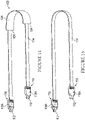
Figure 11 is a right view of the removable crown strap assembly ofFigure 10 . -
Figure 12 is a rear view of the removable crown strap assembly ofFigure 10 . -
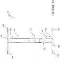
Figure 13 is a top view of the removable crown strap assembly ofFigure 10 . -
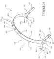
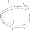
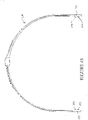
Figure 14 is a side view of a rear strap of the headgear ofFigure 1 . -
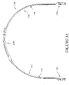
Figure 15 is a side view of the rear strap ofFigure 14 with a rear sleeve removed. -
Figure 16 is a perspective view of the headgear assembly ofFigure 1 shown positioned on a head of a user. -
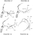
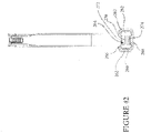
Figure 17 is a perspective view of a latch adjustment mechanism for adjusting a rear strap. -
Figure 18 is a perspective view of a snap adjustment mechanism for adjusting a rear strap. -
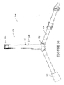
Figure 19 is a perspective view of a telescoping arm adjustment mechanism for adjusting a rear strap. -
Figure 20 is a perspective view of a further arrangement for adjusting a rear strap. -
Figure 21 is a perspective view of a crown strap adjustment configuration. -
Figure 22 is a perspective view of another crown strap adjustment configuration. -
Figure 23 is a perspective view of a headgear assembly. -
Figure 24 is another perspective view of the headgear assembly ofFigure 23 . -
Figure 25 is a side elevation view of the headgear assembly ofFigure 23 . -
Figure 26 is a rear elevation view of the headgear assembly ofFigure 23 . -
Figure 27 is a side elevation view of the headgear assembly ofFigure 23 . -
Figure 28 is a top view of the headgear assembly ofFigure 23 . -
Figure 29 is a front elevation view of the headgear assembly ofFigure 23 . -
Figure 30 is a bottom view of the headgear assembly ofFigure 23 . -
Figure 31 is a perspective view of a crown strap assembly of the headgear assembly ofFigure 23 . -
Figure 32 is a front view of the crown strap assembly ofFigure 31 . -
Figure 33 is an enlarged view of a portion of the crown strap assembly ofFigure 31 . -
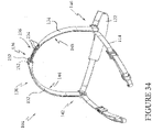
Figure 34 is a perspective view of a headgear assembly. -
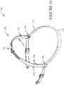
Figure 35 is another perspective view of the headgear assembly ofFigure 34 . -
Figure 36 is a side elevation view of the headgear assembly ofFigure 34 . -
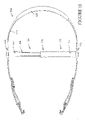
Figure 37 is a rear elevation view of the headgear assembly ofFigure 34 . -
Figure 38 is a side elevation view of the headgear assembly ofFigure 34 . -
Figure 39 is a top view of the headgear assembly ofFigure 34 . -
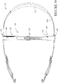
Figure 40 is a front elevation view of the headgear assembly ofFigure 34 . -
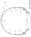
Figure 41 is a bottom view of the headgear assembly ofFigure 34 . -
Figure 42 is a side view of a crown strap assembly of the headgear assembly ofFigure 34 . -
Figure 43 is a rear view of the crown strap assembly ofFigure 42 . -
Figure 44 is an enlarged sectioned view of a portion of the crown strap assembly ofFigure 42 . -
Figure 45 is a perspective view of the crown strap assembly ofFigure 42 . -
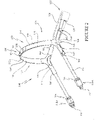
Figure 1 illustrates an interface andheadgear assembly 100 that is arranged and configured in accordance with certain features, aspects and advantages of the present disclosure. Theassembly 100 features aninterface 102 that is removably connectable with aheadgear assembly 104. - The
patient interface 102 can be any suitable type of patient interface. Examples of suitable types of patient interfaces include face masks, oral masks, nasal masks, nasal pillows masks, nasal cannulae, combinations of oral and nasal masks, tracheal masks, and the like. The illustratedinterface 102 is a nasal pillows mask that includes amask frame 106. - In the illustrated configuration, the
mask frame 106 and theheadgear assembly 104 can be joined together using any suitable technique. In the illustrated configuration, a post andhook system 108 is used to join thepatient interface 102 and theheadgear assembly 104. In the illustratedsystem 108, themask frame 106 can include apost 110 or the like while theheadgear assembly 104 can include ahook 112. Thehook 112 can be joined to thepost 110 to connect theheadgear assembly 104 to themask frame 106 and thehook 112 can be separated from thepost 110 to decouple theheadgear assembly 104 from themask frame 106. - The
headgear assembly 104 generally comprises amain strap 114. Themain strap 114 can be configured to extend around the back of the head or neck of the wearer. Themain strap 114 can have any suitable configuration and can be formed of any suitable material. In some configurations, themain strap 114 can be formed of a stretchable material. In some configurations, themain strap 114 comprises a tubular-knitted elastic strap. In some configurations, themain strap 114 can be of any configuration described inWO2010/131189, published on November 18, 2010 , orWO2011/059346, published on May 19, 2011 , each of which is hereby incorporated by reference in its entirety. Themain strap 114 provides an easy donning of the interface andheadgear assembly 100 because themain strap 114 allows the wearer to simply stretch themain strap 114 and fit the interface andheadgear assembly 100 to the head. - In the illustrated configuration, the
main strap 114 comprises two ends 116. With continued reference toFigure 1 , each of the two ends 116 can be connected to acorresponding hook 112. Two different types ofhook members Figure 1 . Additional types ofhook members Figures 17-19 . Any suitable hook member can be used. Thehook members interface 102. In some configurations, thehook members hook members posts 110. - One of the
hook members 118A is designed to create a fixed length to themain strap 114. In other words, a position of the first of the twohook members 118A on or relative to themain strap 114 is not adjustable. Thehook member 118A can capture at least a portion of themain strap 114 or can be secured to themain strap 114 in any other suitable manner. In some configurations, thehook members 118A is an assembly that is overmoulded into position onto themain strap 114. - The second of
hook members 118B is adjustable relative to themain strap 114 and allows the length of themain strap 114 to be adjusted. In the illustrated configuration, thehook member 118B includes an opening through which theend 116 of themain strap 114 can be threaded before being doubled back and secured to itself. In the illustrated configuration, a hook andloop fastener 120 can be used. The hook andloop fastener 120 can include a hook tab that is secured to themain strap 114. In some configurations, the hook tab can be ultrasonically welded, or RF welded, to a nylon, polyester or similar covered substrate, which can form a portion of themain strap 114. In some configurations, the hook portion of the hook andloop fastener 120 can be positioned on the end of thestrap 114 with the loop portion being positioned on the portion of the strap between the two ends of thestrap 114. - With reference to
Figure 17 , the third of thehook members 118C is designed to be adjustable and allows the length of themain strap 114 to be adjusted. Themain strap 114 feeds through afirst latch component 180 and asecond latch component 182. Thefirst latch component 180 and the second latch component can be pivotally connected, for example but without limitation. The position of thehook member 118C along themain strap 114 can be adjusted until thefirst latch component 180 and thesecond latch component 182 are pivoted to a locked position. When in the locked position, thehook member 118C is secured in position along themain strap 114. When in the unlocked position, thehook member 118C can be adjusted along themain strap 114 such that the length of themain strap 114 can be increased and decreased. - With reference to
Figure 18 , the fourth of thehook members 118D also is designed to be adjustable and allows the length of themain strap 114 to be adjusted among a plurality of predetermined lengths. In the illustrated configuration, themain strap 114 includes a plurality ofsnaps 190. Thesnaps 190 away from the end of themain strap 114 cooperate with a portion that is positioned on the end of themain strap 114. As such, the portion that is positioned on the end of themain strap 114 can be moved among the plurality of thesnaps 190 to allow for adjustment. In some configurations, themain strap 114 can be provided with two or three different set points (e.g., to correspond to large, medium and small sizes). Other configurations also are possible keeping in mind the goal of providing for simple, yet effective, adjustability. - With reference to
Figure 19 , the fifth of thehook members 118E is adjustable and allows the length of themain strap 114 to be adjusted through atelescoping mechanism 200. Thetelescoping mechanism 200 generally comprises anouter sleeve member 202 and aninner arm 204. In the illustrated configuration, theouter sleeve member 202 is secured to thestrap 114 while theinner arm 204 is secured to ahook element 206. In some configurations, the orientation is switched. Theouter sleeve member 202 can define an inner passage. The inner passage can include one or more ridges. Theinner arm 204 can include one or more recesses. In some configurations, the outer sleeve member can have recesses on the inner passage while the inner arm includes ridges. Other configurations also are possible. By squeezing theouter sleeve member 202, theinner arm 204 can translate relative to theouter sleeve member 202. In some configurations, theouter sleeve 202 is squeezed in a direction that is generally normal or perpendicular to the interlocking recesses and ridges such that squeezing theouter sleeve 202 results in movement of a portion of theouter sleeve 202 away from theinner arm 204. Accordingly, the illustrated configuration provides adjustability. The adjustability provides a plurality of set points depending upon the distance between the ridges and the recesses. Other detent arrangements, locks and retention arrangements can also be used. - In some configurations, such as that illustrated in
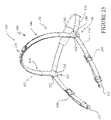
Figure 23 , the adjustability can be provided through the use ofbuckles 230 or the like. Thestrap 114 can be threaded through thehooks 112 and secured to a desired length by threading through thebuckles 230. Other suitable configurations also can be used keeping in mind a desire to provide adjustability to the length of thestrap 114. - As shown in
Figure 15 , in some configurations, themain strap 114 can be used without any further components. In other words, themain strap 114 can be secured to theinterface 102 and provide a retention force to maintain theinterface 102 in position for use. In such configurations, themain strap 114 may also comprise thehook members 118A (or thehook members 118B). - With reference to
Figure 14 , to enhance comfort, asleeve 122 can be positioned along themain strap 114 between the ends 116. Thesleeve 122 can be configured in any suitable manner and the sleeve can be formed of any suitable material. In some configurations, thesleeve 122 is repositionable along themain strap 114 in any location between the ends 116. In some configurations, thesleeve 122 is secured to themain strap 114 and cannot be removed and/or cannot be moved along the length of themain strap 114. - The
sleeve 122 can be formed of polyester, nylon, micro fibre, fleece, or any other suitable materials, including those that are quick drying and/or moisture wicking. In some configurations, thesleeve 122 forms a flattened tube-like structure that defines an elongate passage that terminates atopenings 124. In configurations in which thesleeve 122 is removable, theopenings 124 can be sufficiently large or flexible to accommodate thehook members removable hook members 118B, however, theopenings 124 need not be sufficiently large or flexible to accommodate thehook members 118B. Themain strap 114 can be inserted into one of theopenings 124 and passed through the passage. - The illustrated
sleeve 122 also has acontact surface 126. Thecontact surface 126 is the surface that will be directly in contact with the wearer. In the illustrated configuration, thecontact surface 126 is enlarged relative to the corresponding surface of themain strap 114. In the illustrated configuration, thecontact surface 126 and the opposite surface both can provide an elongate flattened surface. By providing an elongate flattened surface, labeling can be positioned on thesleeve 122, which can be used to provide guidance for the proper orientation of themain strap 114 when donning the interface andheadgear assembly 100. In some configurations, thecontact surface 126 can be provided with surface texturing or the like to enhance gripping on short haired or bald headed patients. - With reference again to
Figure 1 , theheadgear assembly 104 also can comprise acrown strap assembly 130. In some configurations, thecrown strap assembly 130 can be selectively coupled to and decoupled from themain strap 114. By including a detachablecrown strap assembly 130, theheadgear assembly 104 can provide more options to the user, which can enhance the individualized comfort and/or support sought by users. In addition, using thecrown strap assembly 130 can improve stability of theheadgear assembly 104. Moreover, because thecrown strap assembly 130 is designed to pass over the top of the head of the user, using thecrown strap assembly 130 can reduce slippage of themain strap 114 during use. - Turning now to
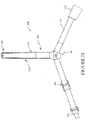
Figures 10-13 , thecrown strap assembly 130 is shown separated from themain strap 114. In the illustrated configuration, thecrown strap assembly 130 is adjustable. Accordingly, the illustratedcrown strap assembly 130 comprises afirst portion 132 and asecond portion 134. Thefirst portion 132 and thesecond portion 134 can be adjustably connected. In the illustrated configuration, anadjustment mechanism 136 couples thefirst portion 132 and thesecond portion 134. Thefirst portion 132 connects to themain strap 114 and thesecond portion 134 while thesecond portion 134 connects to themain strap 114 and thefirst portion 132. In other words, thefirst portion 132 and thesecond portion 134 are connected to themain strap 114 and to each other. In other configurations, thecrown strap 130 is not adjustable and can be constructed as a single piece. - The
adjustment mechanism 136 in the configuration illustrated inFigure 1 comprises a plurality ofapertures 138 and one ormore posts 140. In some configurations, twoposts 140 are provided and threeapertures 138 are provided. The illustrated configuration provides at least three different settings such that theadjustment mechanism 136 provides three different length or height settings for thecrown strap assembly 130. That is, a change in length of thecrown strap 130 changes a height of ends of thecrown strap 130 on a user's head in use. Other types of adjustment mechanisms and other numbers of settings can be used. - The
posts 140 can comprise a stem and a head portion. The head portion of theposts 140 can be very closely sized or slightly oversized relative to theaperture 138. Theapertures 138 can snap fit over the head portions of theposts 140. In such a manner, a secure coupling can be provided. - Other manners of securing the
first portion 132 and thesecond portion 134 together also can be used. For example, as shown inFigure 21 , theadjustment mechanism 136 can include two ormore slots 210 and a plurality oftransverse ridges 212. In the illustrated configuration, thefirst portion 132 comprises twoparallel slots 210. Theslots 210 do not extend the full width of thefirst portion 132. By being generally parallel, theslots 210 can interact with theridges 212 of thesecond portion 134. In some configurations, however, theslots 210 may not be generally parallel. Theridges 212 can extend the full width or at least some portion of the width of thesecond portion 134. By spacing theridges 212 at desired increments, a plurality of discrete and predetermined sizes can be defined for thecrown strap assembly 130. - With reference to
Figure 22 , anotheradjustment mechanism 136 is illustrated. In the illustrated configuration, thefirst portion 132 can include one or more wedges or flaps 220 while thesecond portion 134 can include corresponding slots 222. In some configurations, the same number of wedges/flaps 220 and slots 222 can be used (e.g., 3 wedges/flaps flaps 220 than slots 222 can be provided. In some configurations, more wedges/flaps 220 than slots 222 can be provided. The illustrated configuration provides for adjustability between discrete and predetermined sizes for thecrown strap assembly 130. In some configurations, three or four sizes can be provided. - With reference to
Figure 34 , afurther adjustment mechanism 136 is illustrated. In the illustrated configuration, thefirst portion 132 includes aloop 152 that defines a passageway. Thesecond portion 134 can extend into the passageway defined by theloop 152. In the illustrated configuration, theloop 152 can include atang 232, tab or the like. Thetang 232 can extend into the passageway defined by theloop 152. Thetang 232 is deflectable and, together with a plurality of ridges or recesses 234, can define aratchet mechanism 236. Theratchet mechanism 236 can resist expansion of thecrown strap assembly 130 while allowing adjustability to shorten thecrown strap assembly 130. In some configurations, with enough force applied to thefirst portion 132 and thesecond portion 134, thecrown strap assembly 130 can be lengthened by overpowering theratchet mechanism 236. In some configurations, a release can be provided to move thetang 232 and allow lengthening of thecrown strap assembly 130. Other configurations can be used keeping in mind a desire for a relatively secure adjustment mechanism, such as any suitable detent arrangement, for example. - The
first portion 132 of thecrown strap assembly 130 comprises afirst bridge region 142 and afirst strap region 144. Thesecond portion 134 of thecrown strap assembly 130 similarly comprises asecond bridge region 146 and asecond strap region 148. In some configurations, thefirst portion 132 and thesecond portion 134 are generally symmetrical to each other with the exception of the region that defines theadjustment mechanism 136. Other configurations are possible. - The
first strap region 144 comprises theapertures 138 and, as shown inFigure 6 , may have reduction in width somewhere along its length. In the illustrated configuration, thefirst strap portion 144 comprises atapering zone 150 such that a first width of thefirst strap portion 144 is smaller than a second width of thefirst strap portion 134 that is closer to thefirst bridge region 142. Thesecond strap region 148 comprises at least oneloop 152. In the illustrated configuration, theloop 152 is positioned at an end of thesecond strap region 148 furthest from thesecond bridge region 146. Theloop 152 serves to somewhat restrain thefirst strap region 144 at a location between theposts 140 of thesecond strap region 148 against significant movement away from thesecond strap region 148. - In some configurations, the
loop 152 defines a passage that has a width. The width of the passage is smaller than the second width of thefirst strap region 144 and larger than the first width of thefirst strap region 144. In such configurations, the structure that defines theloop 152 serves to limit the degree to which thefirst strap region 144 can move along thesecond strap region 148. Other configurations also are possible. In addition, the location of features on any strap region can be reversed such that elements shown on one strap region can be positioned on the other. For example, theloop 152 is shown on thesecond strap region 148 inFigure 1 and theloop 152 is shown on the first strap region inFigures 21 and 22 . - With continued reference to
Figure 10 , thesecond strap region 148 comprises one ormore ribs 154. The illustratedribs 154 are elongate members that extend along the lateral edge of at least a portion of thesecond strap region 148. The illustratedribs 154 extend to and connect with theloop 152. Theribs 154 can taper such that a height of theribs 154 reduces in a direction away from theloop 152. The narrower portion of thefirst strap region 144 can fit between theribs 154. In some configurations, theribs 154 in the region that will receive thefirst strap region 144 can be commensurate with the thickness of thefirst strap region 144. By making the two commensurate, the top of theribs 154 and the top surface of thefirst strap region 144 can be generally flush. - With continued reference to
Figure 10 , thesecond bridge region 146 will be described. Thefirst bridge region 142 is generally configured the same as thesecond bridge region 146. In the illustrated configurations, the first andsecond bridge regions - As described above, the illustrated
crown strap assembly 130 is configured for use with a singlemain strap 114. In some configurations, the maincrown strap assembly 130 can be configured to connect with more than one main strap. - In the illustrated configurations, the
second bridge region 146 defines astrap passage 156. In some configurations, thepassage 156 can be defined by three supportingcomponents 158. The supportingcomponents 158 are spaced apart along a length of thesecond bridge region 146. In some configurations, two of the three supportingcomponents 158 are configured to secure themain strap 114 against significant upward movement relative to thesecond bridge region 146 while the third of the three supportingcomponents 158 is configured to secure themain strap 114 against significant downward movement relative to thesecond bridge region 146. In some configurations, all three of the supportingcomponents 158 are configured to secure the main strap against significant downward movement relative to thesecond bridge region 146. - With continued reference to
Figure 10 , at least two of the three supportingcomponents 158 can define interruptedloops 160. The interruptedloops 160 can include a slotted gap or the like. In the illustrated configuration, the slotted gap or the like can be positioned along an upper portion of the associatedloop 160. Each slotted gap can be sized and configured to allow threading of themain strap 114 into thecorresponding loop 160. In the illustrated configuration, theloops 160 are flattened loops with two shorter ends connected to two longer ends and the slotted gap is positioned along one of the two longer ends while the other of the longer ends is defined by amain body 162 of thesecond strap region 148. - The
main body 162 of thesecond bridge region 146 extends between theloops 160 and connects theloops 160 to thesecond strap region 148. Alower lip 164 extends outward from a lower portion of themain body 162. Thelower lip 164 can further resist downward movement of themain strap 114 relative to thesecond strap region 148. Thelower lip 164 can extend outward away from themain body 162 to a degree that generally is commensurate with the outer surface of theloops 160 such that thelower lip 164 and the loops are generally flush with each other. Thelower lip 164 can extend between the supportingcomponents 158 and, in some configurations, can fill the spaces between the supportingcomponents 158. - With continued reference to
Figure 10 , themain body 162 also defines one ormore apertures 166. In the illustrated configuration, theaperture 166 is positioned generally equidistantly to the two ends of thesecond strap region 148. In some configurations, theaperture 166 is positioned generally equidistantly to the two ends of themain body 162. Theaperture 166 can be positioned in the junction between thesecond strap region 148 and thesecond bridge region 146. Other configurations are possible. - In the illustrated configuration, the
medial member 168 of the three supportingcomponents 158 can at least partially overlap with theaperture 166. In the illustrated configuration, themedial member 168 is positioned fully within a region defined as an extension of the outer bound of the aperture 166 (seeFigure 11 ). In some configurations, themedial member 168 is positioned such that at least a portion of the aperture extends further toward the ends of thesecond bridge region 146 relative to the ends of themedial member 168. Themedial member 168 can extend upward away from thelower lip 164. Themedial member 168 can extend upward away from the lower lip 164 a distance that is at least about one-half of a height of themain strap 114. - In some configurations, such as that shown in
Figure 20 , at least one of thebridge region strap region medial member 174. The secondmedial member 174 can be positioned vertical higher than themedial member 168. In some configurations, the secondmedial member 174 can be positioned vertically above themedial member 168. In some configurations, the secondmedial member 174 can be sized and configured identically or substantially identically to themedial member 168. - In some configurations, the second
medial member 174 can define a strap-accommodating passage between the secondmedial member 174 and the at least one of thebridge region strap region medial member 174 advantageously provides further adjustability for theheadgear assembly 104. Thestrap 114 can be supported by one of themedial member 168 or the secondmedial member 174. By moving thestrap 114 to the secondmedial member 174 from themedial member 168, thestrap 114 can be effectively shortened. While the illustrated configuration illustrates twomedial members headgear assembly 104, more than two medial members can be provided on one or both sides of theheadgear assembly 104. - In the illustrated configuration, the
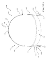
second bridge region 146 arcs upward. In other words, as shown inFigure 11 , acentral region 170 is vertically higher than ends 172 of thesecond bridge region 146. In the illustrated configuration, uppermost portions of theends 172 are positioned lower than a lowermost portion of thecentral region 170. Thesecond bridge region 146 can be configured such that the top of the ear can be bypassed while maintaining a desired headgear vector for theinterface 102 being supported by the headgear. Such an example is illustrated inFigure 16 , for example but without limitation. Moreover, the elongatedmain body 162 provides arms that reduce pivotal movement of themain strap 114 and the vertical extent of themain body 162 combined with the three supporting components can minimize twisting in themain strap 114. Other configurations are possible. - In use, the
main strap 114 can be threaded through the slots in theloops 160 and slid into a gap defined between themedial member 168 and themain body 162 such that themain strap 114 is positioned within theloops 160 and supported by the combination of themain body 162 and themedial member 168. Such a configuration is shown inFigures 1-9 . In this manner, the user of the headgear can adjust the headgear to a desired configuration by adding the strap, removing the strap or resizing the strap. - With reference to
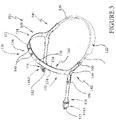
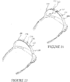
Figures 23-33 , another configuration for the bridge regions will be described. As illustrated, theheadgear assembly 104 comprises thecrown strap assembly 130. Thecrown strap assembly 130 includes thefirst portion 132 and thesecond portion 134 that can be secured together in any suitable manner. However, as described above, thecrown strap 130 can be a single member or otherwise fixed in length. In the illustrated arrangement, thefirst portion 132 includes thefirst bridge region 142 and thefirst strap region 144. Thesecond portion 132 includes thesecond bridge region 146 and thesecond strap region 148. Each of these components can be configured in accordance with any of the description herein. - The
first bridge region 142 and thesecond bridge region 146 can be the same as each other or can be different from each other. In the illustrated configuration, the first andsecond bridge regions - The illustrated
bridge region strap 114. In some configurations, the passageway is linear. In some configurations, the passageway includes a bend. The some configurations, the passageway includes two linear portions that are connected with a bend. - In the illustrated configuration, the
bridge region 142 comprises aninner wall 240 and anouter wall 242 that are connected together. Theinner wall 240 and theouter wall 242 generally combine to define a loop that defines the passageway. Theinner wall 240 preferably is an extension of thestrap region inner wall 240 will be adjacent to the head of the user in use. - At least a portion of the loop is interrupted to define an insertion path for the
strap 114. In the illustrated configuration, theouter wall 242 includes aslot 244 that interrupts theouter wall 242. Theslot 244 is sized, positioned and configured to allow thestrap 114 to be threaded into position within the passageway. Theslot 244 can be generally straight or horizontal. In some configurations, theslot 244 can be slightly arcuate. In some configurations, theslot 244 can be slightly arcuate with a higher mid-portion than the outer portions. In some configurations, the inner wall may be interrupted. In some configurations, an upper or lower portion of the loop may be interrupted. However, by interrupting theinner wall 240 or theouter wall 242, theslot 244 can be positioned along the longer surface of the strap while also allowing thestrap 114 to be secured in the vertical directions (i.e., up and down along the user's head). - With reference now to
Figure 33 , theouter wall 242, as a result of theslot 244, includes anupper portion 246 and alower portion 248 in the illustrated configuration. In some configurations, theupper portion 246 is slightly less open than thelower portion 248. In other words, the distance between theouter wall 242 and theinner wall 240 is greater at thelower portion 248 than at theupper portion 246. Moreover, in the illustrated configuration, the gap that defines the passageway for thestrap 114 is larger at thelower portion 248 than at theupper portion 246. Such a configuration assists in assembly of thestrap 114 into theslot 244 and/or help in retention of thestrap 114 within theslot 244. - With reference now to
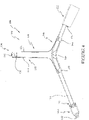
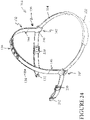
Figures 34-45 , a further configuration for the bridge regions will be described. As illustrated, theheadgear assembly 104 comprises thecrown strap assembly 130. Thecrown strap assembly 130 includes thefirst portion 132 and thesecond portion 134 that can be secured together in any suitable manner. Thefirst portion 132 includes thefirst bridge region 142 and thefirst strap region 144. Thesecond portion 132 includes thesecond bridge region 146 and thesecond strap region 148. Each of these components can be configured in accordance with any of the description herein. - The
first bridge region 142 and thesecond bridge region 146 can be the same as each other or can be different from each other. In the illustrated configuration, the first andsecond bridge regions - The illustrated
bridge region strap 114. The passageway in the arrangement shown inFigures 34-45 differs from the passageways described above. In the arrangement shown inFigures 34-45 , the passageway is defined by two generally vertical slots 260 (seeFigure 42 ). The twoslots 260 are defined by twoouter posts 262 and anintermediate portion 264. Thestrap 114 can be threaded through theslots 260, which allows adjustment of the location of thecrown strap assembly 130 along thestrap 114. - In the illustrated configuration, the
outer posts 262 are connected to each other. Theouter posts 262 can be connected with anupper member 266 and alower member 268. Theouter posts 262,upper member 266 andlower member 268 can define a frame into which thestrap 114 threads. The frame can be a complete (i.e., gapless) frame. As such, theintermediate portion 264 can be interrupted to enable insertion of thestrap 114. In some configurations, one or more of theposts 262 can be interrupted. In some configurations, one or more of theupper member 266 and thelower member 268 can be interrupted. In the illustrated configuration, theintermediate portion 264 is separated into two components by a slot orgap 270. In some configurations, thegap 270 can be positioned such that a single intermediate member is formed. In the illustrated configuration, thegap 270 is positioned such that twointermediate members gap 270 is positioned such that twointermediate members strap 114. Moreover, as shown inFigure 44 , the twointermediate member strap 114 is made easier. For example, one member may be slightly splayed open relative to the other member, similar to the arrangement illustrated inFigure 33 , for example. In the illustrated configuration, thelower member 274 is splayed open slightly more than theupper member 272. Other configurations are possible. - With reference to
Figure 43 , theintermediate members intermediate members outer posts 262, for example. As shown inFigure 44 , theintermediate members outer posts 262. In some configurations, theintermediate members outer posts 262 on a user-side surface. In some configurations, theintermediate members strap 114 through thegap 270 and into position relative to theintermediate portion 264. - Unless the context clearly requires otherwise, throughout the description and the claims, the words "comprise", "comprising", and the like, are to be construed in an inclusive sense as opposed to an exclusive or exhaustive sense, that is to say, in the sense of "including, but not limited to".
- Reference to any prior art in this specification is not, and should not be taken as, an acknowledgement or any form of suggestion that that prior art forms part of the common general knowledge in the field of endeavor in any country in the world.
- The invention may also be said broadly to consist in the parts, elements and features referred to or indicated in the specification of the application, individually or collectively, in any or all combinations of two or more of said parts, elements or features.
- Where, in the foregoing description reference has been made to integers or components having known equivalents thereof, those integers are herein incorporated as if individually set forth.
- It should be noted that various changes and modifications to the presently preferred embodiments described herein will be apparent to those skilled in the art. Such changes and modifications may be made without departing from the spirit and scope of the invention and without diminishing its attendant advantages. For instance, various components may be repositioned as desired. It is therefore intended that such changes and modifications be included within the scope of the invention. Moreover, not all of the features, aspects and advantages are necessarily required to practice the present invention. Accordingly, the scope of the present invention is intended to be defined only by the claims that follow.
- 1. An interface and headgear assembly comprising:
- an interface comprising a frame and a seal supported by the frame;
- a headgear assembly removably connected to the interface, the headgear comprising a first strap configured to connect at a first end to the interface and at a second end to the interface, a crown strap connected to the first strap, the crown strap comprising a first bridge region and a second bridge region, the first bridge region defining a first passage that receives the first strap and the second bridge region defining a second passage that receives the first strap, wherein each of the first bridge region and the second bridge region is adjustable in position relative to the first strap.
- 2. The assembly of
Clause 1, wherein each of the first bridge region and the second bridge region comprises multiple supporting components configured to secure the first bridge region and the second bridge region, respectively, to the first strap. - 3. The assembly of Clause 2, wherein the supporting components comprise a first loop and a second loop configured to receive the strap of the interface and headgear assembly.
- 4. The assembly of
Clause 3, wherein each of the first and second loops is an interrupted loop. - 5. The assembly of
Clause 4, wherein each of the first and second loops comprises an upper portion and a lower portion defining a slot therebetween. - 6. The assembly of
Clause 5, wherein a width of a passageway defined by each of the first and second loops is smaller at the upper portion than at a lower portion. - 7. The assembly of any one of Clauses 3-6, further comprising at least one medial member positioned between the first loop and the second loop and extending vertically upward from a lower lip of the first bridge region.
- 8. The assembly of Clause 7, wherein the at least one medial member supports the first strap at a relatively higher position than a position of the first strap at the first and second loops.
- 9. The assembly of Clause 7 or Clause 8, wherein the at least one medial member comprises a lower medial member and an upper medial member and the first strap can be engaged with either of the lower or upper medial members to adjust an effective length of the first strap.
- 10. The assembly of any one of Clauses 1-9, wherein the crown strap comprises a first strap region and a second strap region, the first strap region and the second strap region being removably coupled together.
- 11. The assembly of Clause 10, wherein the first strap region and the second strap region are coupled by an adjustment mechanism.
- 12. The assembly of Clause 11, wherein the adjustment mechanism comprises a plurality of apertures and one or more posts that are selectively engageable with the plurality of apertures.
- 13. The assembly of Clause 11, wherein the adjustment mechanism comprises two or more slots and a plurality of ridges that are selectively engageable with the one or more slots.
- 14. The assembly of Clause 11, wherein the adjustment mechanism comprises one or more slots and one or more wedges or flaps that are selectively engageable with the one or more slots.
- 15. The assembly of any one of Clauses 1-14, wherein the first strap is constructed from a stretchable material.
- 16. The assembly of Clause 15, wherein the crown strap is constructed from a substantially non-stretchable material.
- 17. The assembly of Clause 16, wherein at least a strap region of the crown strap is constructed from a flexible material.
- 18. The assembly of Clause 17, wherein the material of the strap region has sufficient rigidity such that it is capable of substantially maintaining its shape.
- 19. The assembly of any one of Clauses 1-18, further comprising a sleeve on the first strap.
- 20. The assembly of Clause 19, wherein a surface of the sleeve that contacts a user in use comprises grip-enhancing features.
- This divisional application is divided from
EP19157638.8
Claims (15)
- A removable crown strap assembly (130) configured for use with an interface and headgear assembly, the removable crown strap assembly (130) comprising a first portion (132) comprising a first strap region (144) and a first bridge region (142), and a second portion (134) comprising a second strap region (148) and a second bridge region (146), each of the first bridge region (142) and the second bridge region (146) being configured to receive a strap (114) of the interface and headgear assembly, wherein each of the first bridge region (142) and the second bridge region (146) comprises an inner wall (240) and an outer wall (242) that are connected together to define a loop that defines a passageway that accommodates the strap (114), and wherein at least a portion of the loop is interrupted to define an insertion path for the strap (114).
- The removable crown strap assembly (130) of Claim 1, wherein the passageway is linear.
- The removable crown strap assembly (130) of Claim 1, wherein the passageway includes a bend, preferably wherein the passageway includes two linear portions that are connected with a bend.
- The removable crown strap assembly (130) of any one of Claims 1 to 3, wherein the inner wall (240) is an extension of the strap region (144, 148).
- The removable crown strap assembly (130) of any one of Claims 1 to 4, wherein the outer wall (242) includes a slot (244) that interrupts the outer wall (242) to define an upper portion (246) and a lower portion (248).
- The removable crown strap assembly (130) of Claim 5, wherein the slot (244) is generally straight or horizontal.
- The removable crown strap assembly (130) of Claim 5, wherein the slot (244) is slightly arcuate, preferably wherein the slot (244) has a higher mid-portion than an outer portion.
- The removable crown strap assembly (130) of any one of Claims 5 to 7, wherein the distance between the outer wall (242) and the inner wall (240) is greater at the lower portion (248) than at the upper portion (246).
- The removable crown strap assembly (130) of any one of Claims 5 to 8, wherein a gap that defines the passageway for the strap (114) is larger at the lower portion (248) than at the upper portion (246).
- The removable crown strap assembly (130) of any one of Claims 1-9, wherein the crown strap is not adjustable and is constructed as a single piece.
- The removable crown strap assembly (130) of any one of Claims 1-9, wherein the first strap region (144) and the second strap region (148) are removably coupled together, preferably wherein the first strap region (144) and the second strap region (148) are coupled by an adjustment mechanism (136).
- The removable crown strap assembly (130) of Claim 11, wherein the adjustment mechanism (136) comprises a plurality of apertures and one or more posts that are selectively engageable with the plurality of apertures.
- The removable crown strap assembly (130) of Claim 11, wherein the adjustment mechanism (136) comprises two or more slots and a plurality of ridges that are selectively engageable with the one or more slots.
- The removable crown strap assembly (130) of Claim 11, wherein the adjustment mechanism (136) comprises one or more slots and one or more wedges or flaps that are selectively engageable with the one or more slots.
- The removable crown strap assembly (130) of any one of Claims 1-14, wherein the crown strap is constructed from a substantially non-stretchable material, preferably wherein at least a strap region of the crown strap is constructed from a flexible material, preferably wherein the material of the strap region has sufficient rigidity such that it is capable of substantially maintaining its shape.
Priority Applications (1)
| Application Number | Priority Date | Filing Date | Title |
|---|---|---|---|
| EP23217768.3A EP4353289A2 (en) | 2013-11-27 | 2014-11-27 | Headgear assembly for breathing interface |
Applications Claiming Priority (5)
| Application Number | Priority Date | Filing Date | Title |
|---|---|---|---|
| US201361909936P | 2013-11-27 | 2013-11-27 | |
| US201461990479P | 2014-05-08 | 2014-05-08 | |
| EP19157638.8A EP3546003B1 (en) | 2013-11-27 | 2014-11-27 | Headgear assembly for breathing interface |
| PCT/IB2014/066374 WO2015079396A1 (en) | 2013-11-27 | 2014-11-27 | Headgear assembly for breathing interface |
| EP14865246.4A EP3074074B1 (en) | 2013-11-27 | 2014-11-27 | Headgear assembly for breathing interface |
Related Parent Applications (2)
| Application Number | Title | Priority Date | Filing Date |
|---|---|---|---|
| EP19157638.8A Division EP3546003B1 (en) | 2013-11-27 | 2014-11-27 | Headgear assembly for breathing interface |
| EP14865246.4A Division EP3074074B1 (en) | 2013-11-27 | 2014-11-27 | Headgear assembly for breathing interface |
Related Child Applications (1)
| Application Number | Title | Priority Date | Filing Date |
|---|---|---|---|
| EP23217768.3A Division EP4353289A2 (en) | 2013-11-27 | 2014-11-27 | Headgear assembly for breathing interface |
Publications (2)
| Publication Number | Publication Date |
|---|---|
| EP3978056A1 true EP3978056A1 (en) | 2022-04-06 |
| EP3978056B1 EP3978056B1 (en) | 2023-12-27 |
Family
ID=53198441
Family Applications (4)
| Application Number | Title | Priority Date | Filing Date |
|---|---|---|---|
| EP14865246.4A Active EP3074074B1 (en) | 2013-11-27 | 2014-11-27 | Headgear assembly for breathing interface |
| EP23217768.3A Pending EP4353289A2 (en) | 2013-11-27 | 2014-11-27 | Headgear assembly for breathing interface |
| EP21197638.6A Active EP3978056B1 (en) | 2013-11-27 | 2014-11-27 | Headgear assembly for breathing interface |
| EP19157638.8A Active EP3546003B1 (en) | 2013-11-27 | 2014-11-27 | Headgear assembly for breathing interface |
Family Applications Before (2)
| Application Number | Title | Priority Date | Filing Date |
|---|---|---|---|
| EP14865246.4A Active EP3074074B1 (en) | 2013-11-27 | 2014-11-27 | Headgear assembly for breathing interface |
| EP23217768.3A Pending EP4353289A2 (en) | 2013-11-27 | 2014-11-27 | Headgear assembly for breathing interface |
Family Applications After (1)
| Application Number | Title | Priority Date | Filing Date |
|---|---|---|---|
| EP19157638.8A Active EP3546003B1 (en) | 2013-11-27 | 2014-11-27 | Headgear assembly for breathing interface |
Country Status (5)
| Country | Link |
|---|---|
| US (3) | US10039894B2 (en) |
| EP (4) | EP3074074B1 (en) |
| AU (4) | AU2014356048B2 (en) |
| SG (2) | SG10201607757VA (en) |
| WO (1) | WO2015079396A1 (en) |
Families Citing this family (37)
| Publication number | Priority date | Publication date | Assignee | Title |
|---|---|---|---|---|
| EP2515981B1 (en) | 2009-12-23 | 2021-08-18 | Fisher & Paykel Healthcare Limited | Patient interface and headgear |
| USD691257S1 (en) | 2010-08-23 | 2013-10-08 | Fisher & Paykel Healthcare Limited | Seal for a patient interface |
| USD692554S1 (en) | 2011-09-08 | 2013-10-29 | Fisher & Paykel Healthcare Limited | Patient interface assembly |
| SG10201700946YA (en) | 2012-08-08 | 2017-03-30 | Fisher & Paykel Healthcare Ltd | Headgear for patient interface |
| AU2014356048B2 (en) | 2013-11-27 | 2017-07-20 | Fisher & Paykel Healthcare Limited | Headgear assembly for breathing interface |
| USD770036S1 (en) | 2013-11-27 | 2016-10-25 | Fisher & Paykel Healthcare Limited | Breathing interface assembly |
| USD771238S1 (en) * | 2014-01-16 | 2016-11-08 | Resmed Limited | Combined plenum, seal and clip module for patient interface |
| USD771239S1 (en) | 2014-05-08 | 2016-11-08 | Fisher & Paykel Healthcare Limited | Crown strap of a headgear assembly for a breathing interface |
| US10828452B2 (en) | 2014-09-16 | 2020-11-10 | Fisher & Paykel Healthcare Limited | Intramold headgear |
| US10646680B2 (en) | 2014-09-19 | 2020-05-12 | Fisher & Paykel Healthcare Limited | Headgear assemblies and interface assemblies with headgear |
| USD797921S1 (en) | 2014-11-07 | 2017-09-19 | Fisher & Paykel Healthcare Limited | Breathing apparatus |
| EP3988153B1 (en) | 2015-03-31 | 2024-04-24 | Fisher & Paykel Healthcare Limited | A user interface for supplying gases to an airway |
| WO2016203376A1 (en) * | 2015-06-18 | 2016-12-22 | Koninklijke Philips N.V. | Patient interface device and retention assembly therefor |
| SG11201807479WA (en) | 2016-03-02 | 2018-09-27 | Fisher & Paykel Healthcare Ltd | Nasal respiratory interface and adjustable headgear |
| SG11201807699TA (en) * | 2016-03-16 | 2018-10-30 | Fisher & Paykel Healthcare Ltd | Strap assembly, strap connector, headgear, headgear assembly, method of forming headgear, tubular connector, patient interface and method of joining straps |
| EP3429669B1 (en) | 2016-03-16 | 2022-11-16 | Fisher & Paykel Healthcare Limited | Method for manufacturing a headgear assembly for a respiratory interface |
| AU2017234346B2 (en) | 2016-03-16 | 2022-06-30 | Fisher & Paykel Healthcare Limited | Directional lock for interface headgear arrangement |
| EP3995168A1 (en) | 2016-08-11 | 2022-05-11 | Fisher & Paykel Healthcare Limited | A collapsible conduit, patient interface and headgear connector |
| USD884151S1 (en) | 2016-10-24 | 2020-05-12 | ResMed Pty Ltd | Patient interface |
| USD865158S1 (en) | 2016-11-23 | 2019-10-29 | ResMed Pty Ltd | Respiratory mask |
| USD863545S1 (en) | 2016-11-30 | 2019-10-15 | ResMed Pty Ltd | Air delivery adapter for respiratory mask |
| USD874646S1 (en) | 2017-03-09 | 2020-02-04 | Fisher & Paykel Healthcare Limited | Headgear component for a nasal mask assembly |
| USD851749S1 (en) | 2017-08-01 | 2019-06-18 | Fisher & Paykel Healthcare Limited | Seal for a direct nasal mask assembly |
| USD855793S1 (en) | 2017-09-20 | 2019-08-06 | Fisher & Paykel Healthcare Limited | Frame for a nasal mask |
| USD875242S1 (en) | 2017-09-20 | 2020-02-11 | Fisher & Paykel Healthcare Limited | Nasal mask and breathing tube set |
| AU2018378273A1 (en) * | 2017-12-05 | 2020-06-18 | Fisher & Paykel Healthcare Limited | Headgear assembly with semi-rigid side arms |
| CN117618719A (en) | 2018-03-16 | 2024-03-01 | 费雪派克医疗保健有限公司 | Headgear with lock-release engagement mechanism |
| USD884153S1 (en) | 2018-04-04 | 2020-05-12 | Fisher & Paykel Healthcare Limited | Frame for a mask assembly |
| USD901003S1 (en) | 2018-04-09 | 2020-11-03 | Fisher & Paykel Healthcare Limited | Direct nasal mask assembly |
| US11642483B2 (en) | 2018-06-22 | 2023-05-09 | Koninklijke Philips N.V. | Patient interface stabilization device |
| AU2019328112A1 (en) * | 2018-08-27 | 2021-03-11 | Fisher & Paykel Healthcare Limited | Headgear connectors and headgear for use with or comprising part of a user interface assembly |
| CN109663189A (en) * | 2018-11-28 | 2019-04-23 | 四川省肿瘤医院 | The protective device and preparation method thereof of the fixed frenulum of tracheotomy patients gas bushing |
| EP3990078A4 (en) | 2019-06-28 | 2022-08-31 | ResMed Pty Ltd | Adjustable headgear that is easy to don and doff |
| WO2020261137A1 (en) * | 2019-06-28 | 2020-12-30 | ResMed Asia Pte Ltd | Positioning and stabilising structure for a patient interface |
| CA3160460A1 (en) * | 2019-11-15 | 2021-05-20 | Fisher & Paykel Healthcare Limited | Respiratory interface assembly |
| US20210213230A1 (en) * | 2020-01-15 | 2021-07-15 | Gordon Burry | Cpap/bipap mask strap face protector |
| USD1018837S1 (en) * | 2023-05-22 | 2024-03-19 | Riesiger Sternenhimmel, Inc. | Breathing apparatus |
Citations (6)
| Publication number | Priority date | Publication date | Assignee | Title |
|---|---|---|---|---|
| US6119694A (en) * | 1997-07-24 | 2000-09-19 | Respironics Georgia, Inc. | Nasal mask and headgear |
| US20060081252A1 (en) * | 2004-10-19 | 2006-04-20 | Wood Thomas J | Headgear |
| WO2010131189A1 (en) | 2009-05-12 | 2010-11-18 | Fisher & Paykel Healthcare Limited | Patient interface and aspects thereof |
| WO2011059346A1 (en) | 2009-11-12 | 2011-05-19 | Fisher & Paykel Healthcare Limited | Patient interface and aspects thereof |
| WO2011060479A1 (en) * | 2009-11-20 | 2011-05-26 | Resmed Ltd | Mask system |
| US20110232649A1 (en) * | 2010-03-25 | 2011-09-29 | Respcare, Inc. | Adjustable nasal prong and headgear assembly |
Family Cites Families (93)
| Publication number | Priority date | Publication date | Assignee | Title |
|---|---|---|---|---|
| US2979794A (en) * | 1956-09-24 | 1961-04-18 | Bartolo Francis De | Wire or cable bundle tie |
| US3040741A (en) * | 1958-12-15 | 1962-06-26 | Puritan Compressed Gas Corp | Quick donning harness for oxygen masks |
| GB1045066A (en) * | 1964-10-06 | 1966-10-05 | Westland Aircraft Ltd | Improvements in or relating to breathing attachment |
| US3599635A (en) * | 1969-03-12 | 1971-08-17 | Sierra Eng Co | Hanging quick donning mask suspension |
| US3850168A (en) * | 1971-09-21 | 1974-11-26 | Puritan Bennett Corp | Oxygen mask apparatus |
| US4915106A (en) * | 1988-02-26 | 1990-04-10 | Puritan-Bennett Corporation | Crew oxygen mask with pneumatic comfort adjustment |
| USD335367S (en) | 1991-04-02 | 1993-05-04 | Mieskoski Darlene R | Oxygen mask securing straps |
| FR2691051B1 (en) * | 1992-05-14 | 1996-10-18 | Nicolas Simone | DEVICE FOR ATTACHING A PAIR OF EYEWEAR TO A HEAD COVER. |
| US5394568A (en) | 1993-01-28 | 1995-03-07 | Minnesota Mining And Manufacturing Company | Molded head harness |
| US5517986A (en) * | 1993-09-28 | 1996-05-21 | Respironics, Inc. | Two-point/four-point adjustable headgear for gas delivery mask |
| US5724965A (en) * | 1995-06-06 | 1998-03-10 | Respironics Inc. | Nasal mask |
| US6347631B1 (en) | 1999-11-09 | 2002-02-19 | Mallinckrodt, Inc. | Cantilever device and method for breathing devices and the like |
| US7743767B2 (en) | 2002-04-23 | 2010-06-29 | Resmed Limited | Ergonomic and adjustable respiratory mask assembly with frame |
| NZ604214A (en) | 2002-11-08 | 2014-06-27 | Resmed Ltd | Headgear assembly for a respiratory mask assembly |
| USD561332S1 (en) | 2002-11-08 | 2008-02-05 | Resmed Limited | Portion of a front face of headgear for respiratory mask |
| USD496726S1 (en) | 2002-11-08 | 2004-09-28 | Resmed Limited | Front face of headgear for respiratory mask |
| DE202004021876U1 (en) | 2003-02-21 | 2012-01-30 | Resmed Limited | Nasal arrangement |
| USD542912S1 (en) | 2004-05-28 | 2007-05-15 | Resmed Limited | Mask |
| US7650885B2 (en) * | 2004-06-03 | 2010-01-26 | Paoluccio John A | Mouthpiece and mask for ventilation assistance and connector for joining objects |
| USD532511S1 (en) | 2005-01-03 | 2006-11-21 | Resmed Limited | Headgear for respiratory mask assembly |
| USD532512S1 (en) | 2005-01-03 | 2006-11-21 | Resmed Limited | Headgear for respiratory mask assembly |
| USD536092S1 (en) | 2005-05-10 | 2007-01-30 | Resmed Limited | Headgear for mask |
| US7877817B1 (en) * | 2005-07-15 | 2011-02-01 | Ric Investments, Llc | Mask attachment assembly |
| WO2007022562A1 (en) | 2005-08-22 | 2007-03-01 | Compumedics Limited | Mask assembly |
| US8701668B2 (en) * | 2005-10-14 | 2014-04-22 | Resmed Limited | Nasal assembly |
| US20070163600A1 (en) | 2006-01-11 | 2007-07-19 | Leslie Hoffman | User interface and head gear for a continuous positive airway pressure device |
| US20100224199A1 (en) * | 2006-05-01 | 2010-09-09 | Kimberly-Clark Worldwide, Inc. | Respirator |
| KR100828240B1 (en) | 2006-06-13 | 2008-05-07 | 김종화 | mask of dustproof |
| JP5164854B2 (en) | 2006-12-08 | 2013-03-21 | 帝人ファーマ株式会社 | Headgear and manufacturing method thereof |
| NZ615330A (en) * | 2006-12-15 | 2015-03-27 | Resmed Ltd | Delivery of respiratory therapy |
| CA2687250C (en) | 2007-04-10 | 2015-12-01 | Fanli Meng | Furnace |
| EP2022528B1 (en) | 2007-07-30 | 2016-03-09 | Resmed Limited | Patient interface |
| USD656231S1 (en) | 2009-04-20 | 2012-03-20 | Resmed Limited | Respiratory mask |
| US8800563B2 (en) | 2007-11-05 | 2014-08-12 | Resmed Limited | Headgear for a respiratory mask and a method for donning a respiratory mask |
| USD637279S1 (en) | 2008-01-11 | 2011-05-03 | Resmed Limited | Strap and yoke for mask |
| EP2259827B1 (en) | 2008-03-04 | 2019-10-30 | ResMed Pty Ltd | A foam respiratory mask |
| USD652505S1 (en) | 2008-05-02 | 2012-01-17 | Resmed Limited | Left and right side strap and yoke for a mask |
| US10792451B2 (en) * | 2008-05-12 | 2020-10-06 | Fisher & Paykel Healthcare Limited | Patient interface and aspects thereof |
| US10258757B2 (en) | 2008-05-12 | 2019-04-16 | Fisher & Paykel Healthcare Limited | Patient interface and aspects thereof |
| US8905031B2 (en) | 2008-06-04 | 2014-12-09 | Resmed Limited | Patient interface systems |
| US9072855B2 (en) | 2008-06-12 | 2015-07-07 | Fisher & Paykel Healthcare Limited | Breathing assistance apparatus |
| US20100037897A1 (en) * | 2008-08-14 | 2010-02-18 | RemGenic LLC | Nasal CPAP securement system |
| USD612933S1 (en) | 2008-10-10 | 2010-03-30 | Fisher & Paykel Healthcare Limited | Nasal pillow |
| WO2010051585A1 (en) | 2008-11-07 | 2010-05-14 | Australian Centre For Advanced Medical Technology Pty Ltd | Headgear support for respirator mask |
| EP2373368B2 (en) | 2008-12-10 | 2020-05-06 | ResMed Pty Ltd | Headgear for masks |
| US9095673B2 (en) | 2008-12-15 | 2015-08-04 | Resmed Limited | Unobtrusive nasal mask |
| US9265909B2 (en) * | 2008-12-23 | 2016-02-23 | Koninklijke Philips N.V. | Adjustable headgear |
| USD653748S1 (en) | 2009-04-21 | 2012-02-07 | Resmed Limited | Headgear for a respiratory mask |
| US9248248B2 (en) | 2009-07-17 | 2016-02-02 | Paftec Technologies Pty Ltd | Respirator |
| USD660413S1 (en) | 2009-09-11 | 2012-05-22 | Resmed Limited | Headgear pad for a respiratory mask |
| CA135263S (en) | 2009-11-03 | 2011-10-24 | 3M Innovative Properties Co | Face shield |
| USD704329S1 (en) | 2010-03-25 | 2014-05-06 | Respcare, Inc. | Headgear and nasal pillow assembly |
| USD691257S1 (en) | 2010-08-23 | 2013-10-08 | Fisher & Paykel Healthcare Limited | Seal for a patient interface |
| NZ747496A (en) | 2010-09-30 | 2020-05-29 | ResMed Pty Ltd | Mask system |
| EP3928820B1 (en) | 2010-10-08 | 2023-12-20 | ResMed Pty Ltd | Headgear with first and second adjustment device |
| TWI446940B (en) | 2010-10-13 | 2014-08-01 | Hsiner Co Ltd | Nasal breathing apparatus |
| KR20130120482A (en) | 2010-10-25 | 2013-11-04 | 인슬립 테크놀로지스, 엘엘씨 | Butterfly nasal mask |
| USD685463S1 (en) | 2011-05-05 | 2013-07-02 | ResMed Limitd | Respiratory mask |
| US8839791B2 (en) | 2011-06-22 | 2014-09-23 | Breathe Technologies, Inc. | Ventilation mask with integrated piloted exhalation valve |
| TW201306886A (en) | 2011-08-15 | 2013-02-16 | Hsiner Co Ltd | Nasal-plug type respirator |
| USD692554S1 (en) | 2011-09-08 | 2013-10-29 | Fisher & Paykel Healthcare Limited | Patient interface assembly |
| NZ770002A (en) | 2011-11-15 | 2022-07-01 | ResMed Pty Ltd | Nasal mask system |
| PL3159045T3 (en) | 2011-12-05 | 2022-01-17 | Cleanspace Ip Pty Ltd. | Improved breathing apparatus (papr) |
| US8720444B2 (en) | 2012-01-20 | 2014-05-13 | Hsiner Co., Ltd. | Breathing assistance apparatus having floating function |
| EP3799911B1 (en) | 2012-05-18 | 2023-05-31 | ResMed Pty Ltd | Nasal mask system |
| US20140000614A1 (en) | 2012-07-02 | 2014-01-02 | Eric Chang | Nasal Mask |
| US10232135B2 (en) | 2012-08-03 | 2019-03-19 | Fisher & Paykel Healthcare Limited | Deformable insert for low pressure patient interface |
| SG10201700946YA (en) | 2012-08-08 | 2017-03-30 | Fisher & Paykel Healthcare Ltd | Headgear for patient interface |
| US10460835B2 (en) | 2012-10-01 | 2019-10-29 | Resmed Inc. | System and method for medical device identifier |
| EP2919841B1 (en) * | 2012-11-16 | 2019-08-14 | ResMed Pty Ltd | Positioning and stabilising structure for a patient interface system |
| USD723159S1 (en) | 2012-12-31 | 2015-02-24 | Michelle Pamela Whitfield | Oxygen tube headband |
| EP2943240A1 (en) * | 2013-01-10 | 2015-11-18 | Koninklijke Philips N.V. | Auto-adjusting headgear for a patient interface device |
| US9861778B2 (en) | 2013-03-15 | 2018-01-09 | Resmed Limited | Humidifier reservoir |
| US10398868B2 (en) | 2013-03-27 | 2019-09-03 | Koninklijke Philips N.V. | Nasal prong and patient interface device including the same |
| BR112015026821A2 (en) | 2013-04-26 | 2017-07-25 | Fisher & Paykel Healthcare Ltd | breathing mask head accessory |
| CA153757S (en) | 2013-05-07 | 2014-06-09 | Philips Electronics Ltd | Patient interface assembly |
| USD729381S1 (en) | 2013-05-07 | 2015-05-12 | Koninklijke Philips N.V. | Cushion for a patient interface assembly |
| DE112014003299T5 (en) | 2013-07-17 | 2016-04-21 | Fisher & Paykel Healthcare Limited | Patient connection and manifestations thereof |
| USD737953S1 (en) | 2013-07-26 | 2015-09-01 | Resmed Limited | Patient interface |
| USD743535S1 (en) | 2013-07-26 | 2015-11-17 | Resmed Limited | Headgear for patient interface |
| AU2014356048B2 (en) | 2013-11-27 | 2017-07-20 | Fisher & Paykel Healthcare Limited | Headgear assembly for breathing interface |
| USD770036S1 (en) | 2013-11-27 | 2016-10-25 | Fisher & Paykel Healthcare Limited | Breathing interface assembly |
| USD771239S1 (en) | 2014-05-08 | 2016-11-08 | Fisher & Paykel Healthcare Limited | Crown strap of a headgear assembly for a breathing interface |
| EP3782685B1 (en) | 2014-11-07 | 2023-12-27 | Fisher & Paykel Healthcare Limited | Breathing apparatus |
| USD797921S1 (en) | 2014-11-07 | 2017-09-19 | Fisher & Paykel Healthcare Limited | Breathing apparatus |
| USD810362S1 (en) | 2015-03-24 | 2018-02-13 | Gentex Corporation | Helmet retention system |
| WO2016157040A1 (en) | 2015-03-27 | 2016-10-06 | Fisher & Paykel Healthcare Limited | Patient interface and aspects thereof |
| USD784515S1 (en) | 2015-09-25 | 2017-04-18 | Fisher & Paykel Healthcare Limited | Headgear |
| WO2017158474A2 (en) | 2016-03-18 | 2017-09-21 | Fisher & Paykel Healthcare Limited | Frame and headgear for respiratory mask system |
| USD875242S1 (en) | 2017-09-20 | 2020-02-11 | Fisher & Paykel Healthcare Limited | Nasal mask and breathing tube set |
| USD870977S1 (en) | 2017-09-22 | 2019-12-24 | 3M Innovative Properties Company | Headband |
| USD854758S1 (en) | 2018-03-07 | 2019-07-23 | Lincoln Global, Inc. | Headgear of helmet |
| US10905840B2 (en) | 2018-07-17 | 2021-02-02 | Foxxmed Ltd. | Nasal cannula device |
-
2014
- 2014-11-27 AU AU2014356048A patent/AU2014356048B2/en active Active
- 2014-11-27 EP EP14865246.4A patent/EP3074074B1/en active Active
- 2014-11-27 EP EP23217768.3A patent/EP4353289A2/en active Pending
- 2014-11-27 SG SG10201607757VA patent/SG10201607757VA/en unknown
- 2014-11-27 SG SG10202111455XA patent/SG10202111455XA/en unknown
- 2014-11-27 EP EP21197638.6A patent/EP3978056B1/en active Active
- 2014-11-27 US US15/037,304 patent/US10039894B2/en active Active
- 2014-11-27 WO PCT/IB2014/066374 patent/WO2015079396A1/en active Application Filing
- 2014-11-27 EP EP19157638.8A patent/EP3546003B1/en active Active
-
2017
- 2017-10-12 AU AU2017245368A patent/AU2017245368A1/en not_active Abandoned
-
2018
- 2018-07-16 US US16/036,567 patent/US11786688B2/en active Active
-
2019
- 2019-09-20 AU AU2019232901A patent/AU2019232901B2/en active Active
-
2022
- 2022-01-17 AU AU2022200259A patent/AU2022200259A1/en active Pending
-
2023
- 2023-09-13 US US18/466,435 patent/US20240066252A1/en active Pending
Patent Citations (6)
| Publication number | Priority date | Publication date | Assignee | Title |
|---|---|---|---|---|
| US6119694A (en) * | 1997-07-24 | 2000-09-19 | Respironics Georgia, Inc. | Nasal mask and headgear |
| US20060081252A1 (en) * | 2004-10-19 | 2006-04-20 | Wood Thomas J | Headgear |
| WO2010131189A1 (en) | 2009-05-12 | 2010-11-18 | Fisher & Paykel Healthcare Limited | Patient interface and aspects thereof |
| WO2011059346A1 (en) | 2009-11-12 | 2011-05-19 | Fisher & Paykel Healthcare Limited | Patient interface and aspects thereof |
| WO2011060479A1 (en) * | 2009-11-20 | 2011-05-26 | Resmed Ltd | Mask system |
| US20110232649A1 (en) * | 2010-03-25 | 2011-09-29 | Respcare, Inc. | Adjustable nasal prong and headgear assembly |
Also Published As
| Publication number | Publication date |
|---|---|
| AU2014356048B2 (en) | 2017-07-20 |
| EP3074074B1 (en) | 2019-02-20 |
| SG10201607757VA (en) | 2016-11-29 |
| SG10202111455XA (en) | 2021-12-30 |
| EP3978056B1 (en) | 2023-12-27 |
| US20240066252A1 (en) | 2024-02-29 |
| EP3074074A1 (en) | 2016-10-05 |
| EP4353289A2 (en) | 2024-04-17 |
| EP3074074A4 (en) | 2017-07-19 |
| AU2022200259A1 (en) | 2022-02-10 |
| US11786688B2 (en) | 2023-10-17 |
| US20180318541A1 (en) | 2018-11-08 |
| AU2019232901B2 (en) | 2021-10-21 |
| AU2014356048A1 (en) | 2016-06-02 |
| US20160287830A1 (en) | 2016-10-06 |
| EP3546003B1 (en) | 2021-09-22 |
| US10039894B2 (en) | 2018-08-07 |
| EP3546003A1 (en) | 2019-10-02 |
| AU2017245368A1 (en) | 2017-11-02 |
| WO2015079396A1 (en) | 2015-06-04 |
| AU2019232901A1 (en) | 2019-10-10 |
Similar Documents
| Publication | Publication Date | Title |
|---|---|---|
| AU2019232901B2 (en) | Headgear assembly for breathing interface | |
| JP7358587B2 (en) | Nasal cannula assembly and related parts | |
| CN107106806B (en) | Breathing apparatus | |
| JP2022132284A (en) | Headgear for breathing mask | |
| EP3193995B1 (en) | Patient interface | |
| US20230355908A1 (en) | Yoke for headgear | |
| JP2012513231A (en) | Adjustable headgear | |
| WO2012104756A1 (en) | Patient interface device having selectively positionable multi-band headgear |
Legal Events
| Date | Code | Title | Description |
|---|---|---|---|
| PUAI | Public reference made under article 153(3) epc to a published international application that has entered the european phase |
Free format text: ORIGINAL CODE: 0009012 |
|
| STAA | Information on the status of an ep patent application or granted ep patent |
Free format text: STATUS: THE APPLICATION HAS BEEN PUBLISHED |
|
| AC | Divisional application: reference to earlier application |
Ref document number: 3074074 Country of ref document: EP Kind code of ref document: P Ref document number: 3546003 Country of ref document: EP Kind code of ref document: P |
|
| AK | Designated contracting states |
Kind code of ref document: A1 Designated state(s): AL AT BE BG CH CY CZ DE DK EE ES FI FR GB GR HR HU IE IS IT LI LT LU LV MC MK MT NL NO PL PT RO RS SE SI SK SM TR |
|
| STAA | Information on the status of an ep patent application or granted ep patent |
Free format text: STATUS: REQUEST FOR EXAMINATION WAS MADE |
|
| 17P | Request for examination filed |
Effective date: 20221003 |
|
| RBV | Designated contracting states (corrected) |
Designated state(s): AL AT BE BG CH CY CZ DE DK EE ES FI FR GB GR HR HU IE IS IT LI LT LU LV MC MK MT NL NO PL PT RO RS SE SI SK SM TR |
|
| GRAP | Despatch of communication of intention to grant a patent |
Free format text: ORIGINAL CODE: EPIDOSNIGR1 |
|
| STAA | Information on the status of an ep patent application or granted ep patent |
Free format text: STATUS: GRANT OF PATENT IS INTENDED |
|
| P01 | Opt-out of the competence of the unified patent court (upc) registered |
Effective date: 20230526 |
|
| INTG | Intention to grant announced |
Effective date: 20230627 |
|
| GRAS | Grant fee paid |
Free format text: ORIGINAL CODE: EPIDOSNIGR3 |
|
| GRAA | (expected) grant |
Free format text: ORIGINAL CODE: 0009210 |
|
| STAA | Information on the status of an ep patent application or granted ep patent |
Free format text: STATUS: THE PATENT HAS BEEN GRANTED |
|
| AC | Divisional application: reference to earlier application |
Ref document number: 3074074 Country of ref document: EP Kind code of ref document: P Ref document number: 3546003 Country of ref document: EP Kind code of ref document: P |
|
| AK | Designated contracting states |
Kind code of ref document: B1 Designated state(s): AL AT BE BG CH CY CZ DE DK EE ES FI FR GB GR HR HU IE IS IT LI LT LU LV MC MK MT NL NO PL PT RO RS SE SI SK SM TR |
|
| REG | Reference to a national code |
Ref country code: GB Ref legal event code: FG4D |
|
| REG | Reference to a national code |
Ref country code: CH Ref legal event code: EP |
|
| REG | Reference to a national code |
Ref country code: DE Ref legal event code: R096 Ref document number: 602014089247 Country of ref document: DE |
|
| REG | Reference to a national code |
Ref country code: IE Ref legal event code: FG4D |
|
| PG25 | Lapsed in a contracting state [announced via postgrant information from national office to epo] |
Ref country code: GR Free format text: LAPSE BECAUSE OF FAILURE TO SUBMIT A TRANSLATION OF THE DESCRIPTION OR TO PAY THE FEE WITHIN THE PRESCRIBED TIME-LIMIT Effective date: 20240328 |
|
| REG | Reference to a national code |
Ref country code: LT Ref legal event code: MG9D |
|
| PG25 | Lapsed in a contracting state [announced via postgrant information from national office to epo] |
Ref country code: LT Free format text: LAPSE BECAUSE OF FAILURE TO SUBMIT A TRANSLATION OF THE DESCRIPTION OR TO PAY THE FEE WITHIN THE PRESCRIBED TIME-LIMIT Effective date: 20231227 |