EP3977692B1 - Éviter la gigue dans un système de communication - Google Patents
Éviter la gigue dans un système de communication Download PDFInfo
- Publication number
- EP3977692B1 EP3977692B1 EP20719384.8A EP20719384A EP3977692B1 EP 3977692 B1 EP3977692 B1 EP 3977692B1 EP 20719384 A EP20719384 A EP 20719384A EP 3977692 B1 EP3977692 B1 EP 3977692B1
- Authority
- EP
- European Patent Office
- Prior art keywords
- packet
- received
- slot
- time
- point
- Prior art date
- Legal status (The legal status is an assumption and is not a legal conclusion. Google has not performed a legal analysis and makes no representation as to the accuracy of the status listed.)
- Active
Links
- 238000004891 communication Methods 0.000 title claims description 39
- 238000000034 method Methods 0.000 claims description 38
- 239000000872 buffer Substances 0.000 claims description 17
- 238000004590 computer program Methods 0.000 claims description 6
- 238000012545 processing Methods 0.000 claims description 6
- 230000006870 function Effects 0.000 description 31
- 238000010586 diagram Methods 0.000 description 10
- 238000013459 approach Methods 0.000 description 2
- 230000003111 delayed effect Effects 0.000 description 2
- 238000013461 design Methods 0.000 description 2
- 238000004519 manufacturing process Methods 0.000 description 2
- 230000006855 networking Effects 0.000 description 2
- 230000004044 response Effects 0.000 description 2
- 230000011664 signaling Effects 0.000 description 2
- 238000003491 array Methods 0.000 description 1
- 230000005540 biological transmission Effects 0.000 description 1
- 230000000903 blocking effect Effects 0.000 description 1
- 238000013500 data storage Methods 0.000 description 1
- 230000001419 dependent effect Effects 0.000 description 1
- 238000011161 development Methods 0.000 description 1
- 238000005516 engineering process Methods 0.000 description 1
- 238000011156 evaluation Methods 0.000 description 1
- 238000010295 mobile communication Methods 0.000 description 1
- 230000003287 optical effect Effects 0.000 description 1
- 230000001360 synchronised effect Effects 0.000 description 1
Images


Classifications
-
- H—ELECTRICITY
- H04—ELECTRIC COMMUNICATION TECHNIQUE
- H04L—TRANSMISSION OF DIGITAL INFORMATION, e.g. TELEGRAPHIC COMMUNICATION
- H04L47/00—Traffic control in data switching networks
- H04L47/10—Flow control; Congestion control
- H04L47/28—Flow control; Congestion control in relation to timing considerations
- H04L47/283—Flow control; Congestion control in relation to timing considerations in response to processing delays, e.g. caused by jitter or round trip time [RTT]
-
- H—ELECTRICITY
- H04—ELECTRIC COMMUNICATION TECHNIQUE
- H04L—TRANSMISSION OF DIGITAL INFORMATION, e.g. TELEGRAPHIC COMMUNICATION
- H04L47/00—Traffic control in data switching networks
- H04L47/10—Flow control; Congestion control
- H04L47/24—Traffic characterised by specific attributes, e.g. priority or QoS
- H04L47/2416—Real-time traffic
-
- H—ELECTRICITY
- H04—ELECTRIC COMMUNICATION TECHNIQUE
- H04L—TRANSMISSION OF DIGITAL INFORMATION, e.g. TELEGRAPHIC COMMUNICATION
- H04L47/00—Traffic control in data switching networks
- H04L47/10—Flow control; Congestion control
- H04L47/24—Traffic characterised by specific attributes, e.g. priority or QoS
- H04L47/2491—Mapping quality of service [QoS] requirements between different networks
-
- H—ELECTRICITY
- H04—ELECTRIC COMMUNICATION TECHNIQUE
- H04L—TRANSMISSION OF DIGITAL INFORMATION, e.g. TELEGRAPHIC COMMUNICATION
- H04L47/00—Traffic control in data switching networks
- H04L47/10—Flow control; Congestion control
- H04L47/32—Flow control; Congestion control by discarding or delaying data units, e.g. packets or frames
-
- H—ELECTRICITY
- H04—ELECTRIC COMMUNICATION TECHNIQUE
- H04L—TRANSMISSION OF DIGITAL INFORMATION, e.g. TELEGRAPHIC COMMUNICATION
- H04L47/00—Traffic control in data switching networks
- H04L47/50—Queue scheduling
- H04L47/56—Queue scheduling implementing delay-aware scheduling
-
- H—ELECTRICITY
- H04—ELECTRIC COMMUNICATION TECHNIQUE
- H04L—TRANSMISSION OF DIGITAL INFORMATION, e.g. TELEGRAPHIC COMMUNICATION
- H04L47/00—Traffic control in data switching networks
- H04L47/70—Admission control; Resource allocation
- H04L47/82—Miscellaneous aspects
- H04L47/826—Involving periods of time
-
- H—ELECTRICITY
- H04—ELECTRIC COMMUNICATION TECHNIQUE
- H04L—TRANSMISSION OF DIGITAL INFORMATION, e.g. TELEGRAPHIC COMMUNICATION
- H04L69/00—Network arrangements, protocols or services independent of the application payload and not provided for in the other groups of this subclass
- H04L69/28—Timers or timing mechanisms used in protocols
-
- H—ELECTRICITY
- H04—ELECTRIC COMMUNICATION TECHNIQUE
- H04W—WIRELESS COMMUNICATION NETWORKS
- H04W8/00—Network data management
- H04W8/02—Processing of mobility data, e.g. registration information at HLR [Home Location Register] or VLR [Visitor Location Register]; Transfer of mobility data, e.g. between HLR, VLR or external networks
- H04W8/04—Registration at HLR or HSS [Home Subscriber Server]
Definitions
- This disclosure relates to avoiding jitter in a communication system.
- Some communication devices e.g., sensors, robots, controllers, etc.
- Some production processes are highly sensitive to network jitter (or jitter for short).
- Jitter is generally known as the variation in the delay of received protocol data units PDUs (e.g., IP packets, Ethernet frames, TCP segments, etc.).
- PDUs protocol data units
- packets are sent by a transmitting device in a continuous stream with the packets being spaced evenly apart (e.g. one packet is sent every 10 ms). Due to network congestion, improper queuing, or configuration errors, this steady stream of packets can become "lumpy" (i.e., the delay between each packet can vary instead of being a constant of 10 ms).
- causes of jitter include: a) radio coverage issues; b) radio capacity issues; and c) other connectivity network issues.
- Mobile communication devices associated with considerable amount of data can cause radio related jitter by blocking signals and/or overloading a radio link.
- Time-Sensitive Networking is a set of standards under development by the Time-Sensitive Networking task group of the IEEE 802.1 working group.
- the TSN standards aim to provide technology that will be able to provide manufacturing industries with deterministic, guaranteed latencies, and extremely low packet loss services.
- TSN Ethernet frames can provide on-time delivery of TSN Ethernet frames. It defines a means to transmit certain TSN Ethernet frames on a schedule. Because all network elements share the same time, end devices and bridges implementing Qbv can deliver critical communication very quickly and with no discernible jitter in delivery.
- FIG. 1 illustrates how TSN can be integrated with a communication network 100 (e.g., a 3GPP network).
- the communication network 100 is a 3GPP 5G network comprising a 5G user plane function (UPF) 104 in communication with a 5G base station (gNB) 104 in wireless communication with a user equipment (UE) 102 (a UE is any communication device that is able to wirelessly communicate with gNB 104).
- network 100 may further include a first TSN translator (TT) 111 for interfacing with a TSN bridge 121 or end-host 131 and a second TT 112 for interfacing with a TSN bridge 122 or end-host 132.
- TT TSN translator
- the basic principle is that the communication network 100 is seen as a virtual TSN bridge 106 (a.k.a., TSN switch).
- latency in a communication network may have large variations from time to time due to several uncertainties in the communication network (e.g. radio channel conditions, network routing paths). For example, there may be a significant difference between the uplink maximal latency (e.g., 4.1 ms) and the downlink maximal latency (2.2 ms) due to the asymmetric characteristics from the radio system implementation.
- the uplink and downlink latencies may have a large variation (e.g., from 0.33 ms to 4.1 ms for the uplink traffic and 0.33 ms to 2.2 ms for the downlink traffic).
- US 2010/034212 A1 proposes a de-jitter solution based on timestamped packets and processing at the receiving end.
- "Study on enhancement of 5GS for Vertical and LAN Services” discloses enhancements to 5GS that are required to support TSNs in 5G systems.
- a de-jitter function can be deployed to hold-and-forward packets such that the packets are delivered with an agreed fixed latency of L ms.
- the de-jitter function can be placed at the edge of the virtual 5G TSN switch (e.g. the de-jitter function can be deployed as part of a UPF for uplink (UL) packets and/or it can be deployed as part of a UE for downlink (DL) packets).
- the TSN can consider the communication network as generally having a consistent, deterministic latency of L ms with no jitter.
- the de-jitter function employs a de-jitter buffer (a.k.a., "playout” buffer or “transmit” buffer) that is used to hold received packets for a certain amount of time (a.k.a., the packet hold time) so that the agreed fixed latency (a.k.a., "maximum packet-hold time” or “desired packet delay”) is achieved and jitter is avoided (i.e., the spacing between packets is preserved such that the pace of outgoing packets can be made equal to the pace of incoming packets).
- a de-jitter buffer a.k.a., "playout” buffer or “transmit” buffer
- the de-jitter function may delay the forwarding of the packet (i.e., not forward the packet immediately upon receiving the packet) so that the packet will have a total delay equal to the desired packet delay (i.e., the agreed fixed latency).
- the desired packet delay is a function of maximum latency (e.g., it is usually equal to or greater than the maximum latency that may occur when a packet is forwarded through the wireless network).
- the 3GPP conference paper R2-1814992 states: "For the TSN requirements evaluation in RAN, we only need to consider maximum allowable latency value and can disregard jitter.” This means that the maximum packet-hold time (or desired packet delay) should be set based on the worst-case scenario (i.e., the maximum latency).
- each packet received at the ingress point (e.g., TT 111 for UL packet or TT 112 for DL packets) is modified to include a timestamp indicating the absolute time at which the packet was received at the ingress point and then the modified packet is forwarded to the egress point (e.g., TT 112 for UL packets or TT 111 for DL packets).
- the egress point can use the timestamp in the packet to calculate the total delay experienced by the packet in travelling from the ingress point to the egress point.
- the egress point can use its clock to determine the absolute time at which the packet was received at the egress point and then subtract from this the time specified by the timestamp. We shall denote this calculated delay as D. If the agreed fixed latency is L, then the egress point will hold the packet for an amount of time equal to L minus D and then forward to packet towards the end-host, thereby ensuring that the packet experiences the agreed fixed latency of L. In this way, all packets traversing the communication network will experience the same deterministic agreed latency.
- a problem with the above described implementation is that such timestamping is a very challenging task, particular when the spacing between packets is small (e.g., each micro-second a new packet arrives at the ingress point).
- this disclosure discloses methods for providing a deterministic delay that does not rely on use of such timestamps. For example, instead of the ingress point modifying a packet, which is received within a particular time slot, to include a timestamp indicating the absolute time, the ingress point modifies the received packet to include a slot identifier indicating the particular time slot in which the packet was received, and then the ingress point forwards the modified packet to the egress point.
- the egress point When the egress point receives the modified packet, the egress point removes the slot identifier from the packet and, based on the slot identifier that was included in the packet and the agreed latency (i.e., L), the egress point determines the slot in which to transmit the packet towards the end-host. For example, in one embodiment, if the agreed latency is L microseconds and the slot identifier in the packet identified that the packet was received in "input" slot 3, then the egress point will transmit the packet towards the end-host in "output" slot 3 where the time difference between the beginning of input slot 3 and the beginning of output slot 3 is L microseconds.
- the agreed latency is L microseconds and the slot identifier in the packet identified that the packet was received in "input" slot 3
- the egress point will transmit the packet towards the end-host in "output" slot 3 where the time difference between the beginning of input slot 3 and the beginning of output slot 3 is L microseconds.
- a method that includes an ingress point of a communication network receiving a packet, wherein the packet is received at a time that is within a particular time slot.
- the method further includes the ingress point creating a modified packet that includes the received packet and a slot identifier indicating the particular input time slot in which the packet was received.
- the method further includes the ingress point transmitting the modified packet towards an egress point.
- the ingress point creates the modified packet by adding a tag to the packet, wherein the tag comprises the slot identifier.
- the received packet is an Ethernet frame and the tag is an Ethernet Redundancy tag (R-TAG) that is added to the Ethernet header of the Ethernet frame.
- R-TAG Ethernet Redundancy tag
- the R-TAG consists of six octets and the slot identifier is contained within the last two octets of the R-TAG.
- the method also includes the ingress point, during at least a period of time, incrementing a slot counter value every T units of time, wherein T represents an amount of time between slots.
- the slot identifier is the value of the slot counter at the time the ingress point received the packet.
- the ingress point initializes the slot counter value to an initial value at a predetermined ingress slot open time and thereafter increments the slot counter value every T units of time.
- the packet is part of a particular packet stream and the method further comprises the ingress point initializing the slot counter value to an initial value in response to receiving the first packet of the particular packet stream.
- FIG. 2 illustrates a network 200 in which a de-jitter function is a component of a network node (e.g., UPF or TT) 206.
- the de-jitter function may be located in other devices (e.g., a user equipment 202 and/or 222) as well.
- Network 200 includes user equipments (UEs) 202 and 222, which are devices capable of wireless communication with an access point (e.g. access point 204) (e.g., a 3GPP base station, such as, for example, a 3GPP 5G base station (gNB)).
- UEs 202 and 222 may be a controller (or a component of a controller) that is used to control equipment in a factory. As shown in FIG.
- each UE 202, 222 comprises a TT module.
- UEs 202, 222 are ingress points and network node 206 is an egress point.
- the network node 206 would be the ingress point and at least one of the UEs would be the egress point.
- Access point 204 is communicatively connected to network node 206 (e.g., a gateway, a switch).
- Network node 206 includes a de-jitter function 208 that employs a de-jitter buffer 210 to hold packets received from access point 204 for the purpose of removing jitter from a stream of packets.
- Each of UEs 202 and 222 obtain packets (e.g., generate packets or receive packets from another device, such as, for example, a TSN end-host or TSN bridge) and wirelessly forward the obtained packets. In the example, shown both UE 202 and UE 222 forward their obtained packets to network node 206 via access point 204.
- UEs 202 and 222 may communicate with network node 206 via different access points.
- UE 202 may communicate with network node 206 via access point 204 while UE 222 communicates with a different UPF via a different access point.
- FIG. 3 illustrates an example packet timing diagram, which illustrates a fluctuation in UL packet latencies (e.g., packets transmitted by UE 202).
- the top timeline 302 illustrates the time slot in which each packet in a sequence of packets (i.e., packets P1 to P5) are obtained (e.g., received or generated) by UE 202 (these are referred to as the "Ingress Arrival Times").
- UE 202 is a component of a device (e.g., a robot control device) and another component of the device (e.g., a controller) generates the sequence of packets and provides the packets to UE 202 (i.e., UE 202 receives the packets generated by the other component of the device).
- the Ingress Arrival Time may be the time at which these packets generated by the other component are received at UE 202.
- the middle timeline 304 illustrates the times at which packets P1 to P5 are received at network node 206 (these are referred to as the "Buffer Arrival Times").
- the bottom time line 306 illustrates the times at which packets P1 to P5 are forwarded by the network node 206 to the next device (e.g., TSN bridge, controller, etc.) (these are referred to as the "Buffer Departure Times").
- FIG. 3 demonstrates, there is a variable latency between UE 202 and network node 206 because some packets transmitted by UE 202 to network node 206 are delayed more than other packets. For instance, packet P2 experienced a delay of d2, whereas packet P3 experienced a delay of d3 (d3 ⁇ d2). Accordingly, the sequence of packets experiences jitter.
- network node 206 utilizes de-jitter function 208, which i) employs de-jitter buffer 210 to hold each packet for a certain amount of time (referred to as the "packet hold time") and ii) then forwards the packet when the packet hold time has elapsed.
- de-jitter function 208 employs de-jitter buffer 210 to hold each packet for a certain amount of time (referred to as the "packet hold time") and ii) then forwards the packet when the packet hold time has elapsed.
- the amount of time that each packet originating from UE 202 (which we will now refer to a UEa) is held in the de-jitter buffer 201 is a function of La, where La is the maximum packet-hold time for UEa (i.e., the agreed upon latency for UEa).
- the maximum packet-hold time is typically based on a worst-case scenario-the maximum latency.
- La is large enough so that 99.99999% packets are ensured to go through without dropping (packet loss). At the same time, La should be as small as possible.
- de-jitter function 208 holds each packet originating from UEb for an amount of time equal to: Lb - di, where Lb may or may not be equal La and di is the actual delay experienced by packet di. That is, the maximum latency for UEb may be different than the maximum latency for UEa due to UEb experiencing different radio conditions than UEa.
- the de-jitter function 208 holds received UL packets for a certain amount of time so that the agreed fixed latency (e.g., La, Lb) is achieved and jitter is avoided (i.e., the pace of outgoing packets can be made equal to the pace of incoming packets).
- the agreed fixed latency e.g., La, Lb
- jitter is avoided (i.e., the pace of outgoing packets can be made equal to the pace of incoming packets).
- a de-jitter function just like de-jitter function 208 may be a component of UEa and UEb.
- the de-jitter function may delay the forwarding of the packet (i.e., not forward the packet immediately upon receiving the packet) so that the packet will have a total delay equal to the desired packet delay (i.e., the agreed fixed latency).
- the desired packet delay is a function of maximum latency (e.g., it is usually equal to or greater than the maximum latency that may occur when a packet is forwarded through the wireless network). That is, to ensure that packets are not dropped, La and Lb should be at least as large as the maximal latency.
- a single maximal latency is not an optimal approach because the packets from UEa will be buffered longer than they need to be.
- FIG. 4 and 5 illustrate a process 400 performed by an ingress point (e.g., network node 206 for DL packets and UE 202 for UL packets) and a process 500 performed by an egress point (e.g., network node 206 for UL packets and UE 202 for DL packets), respectively.
- an ingress point e.g., network node 206 for DL packets and UE 202 for UL packets
- an egress point e.g., network node 206 for UL packets and UE 202 for DL packets
- Step s402 comprises the ingress point of the communication network receiving a packet that is part of a packet stream (a.k.a., packet flow), wherein the packet is received at the ingress point at a time within a particular time slot.
- each packet stream may have a different "time slot spacing" (i.e., the interval of time between the beginning of slot i and the beginning of slot i+1).
- the time slot spacing is also referred to as the "slot cycle.” It is assumed here that during any given slot, the ingress point receives at most a single packet.
- Step s404 comprises the ingress point creating a modified packet that includes the received packet and a slot identifier indicating the particular time slot in which the packet was received.
- the ingress point creates the modified packet by adding the slot identifier to the received packet (e.g., adding the slot identifier to a header or payload portion of the received packet), thereby creating the modified packet.
- the ingress point adds the slot identifier to the received packet by adding a tag to the packet, wherein the tag comprises the slot identifier.
- the received packet is an Ethernet frame and the tag is an Ethernet Redundancy tag (R-TAG) that is added to the Ethernet header of the Ethernet frame.
- the R-TAG consists of six octets and, in one embodiment, the slot identifier is contained within the last two octets of the R-TAG.
- Step s406 comprises the ingress point transmitting the modified packet towards an egress point.
- the slot identifier is determined based on a slot counter value that is periodically incremented.
- the ingress point increments the slot counter value every T units of time, where T is the amount of time between slots (i.e., T is the "time slot spacing" or "slot cycle"). Because each packet stream may have a different value of T, the ingress point may maintain a different slot counter value for each packet stream that it receives.
- the ingress point can set the slot counter value to an initial value (e.g., 0 or some other initial value) and then increment the slot counter value by 1 every 3 microseconds.
- the ingress point sets the slot counter value to the initial value and then begins the process of incrementing the counter based on the slot cycle. In this way, when the ingress point receives each packet in the stream, the slot identifier for the packet can simply be equal to the slot counter value at the time the packet was received.
- the ingress point sets the slot counter value to the initial value and then begins the process of incrementing the counter based on the slot cycle. In this way, when the ingress point receives each packet in the stream, the slot identifier for the packet can simply be equal to the slot counter value.
- the slot identifier for packets P1-P5 may be 0, 2, 3, 6, and 8, respectively.
- the slot identifier for packet Pi will indicate the particular time slot in which the packet was received at the ingress point by specifying the number of slots between packet Pi and P1.
- This proposed solution is resistant to possible error situations. For example, if packet loss occurs inside the communication network 200 it will not impact the delivery of the other packets belonging to the same stream. A packet loss results in no packet transmission at the egress in the given time slot because of the pairing of slot identifier and egress time slot.
- the egress point's slot counter is synchronized with the ingress point's slot counter (i.e., both the ingress and egress activate their respective slot counters at the same time)
- the egress point will transmit packets P1-P5 in output slots 3, 5, 6, 9, and 11, respectively.
- the ingress point After the ingress points determines the value of the slot counter when a packet arrives, the ingress point resets the slot counter value to the initial value (e.g., 0) and then resumes incrementing the slot counter value by 1 every T units of time.
- the slot identifier for packets P2-P5 in this alternative example would be 2, 1, and 3, respectively. In this way the slot identifier for packet Pi will indicate the particular time slot in which the packet was received at the ingress point by specifying the number of slots between packet Pi and Pi-1.
- the egress point's slot counter is reset and then resumes incrementing the slot counter value by 1 every T units of time, then the egress point will transmit packets P2-P5 in output slots 2, 1, and 3, respectively (this assume that the egress will hold the first packet for at least L - d1).
- the embodiments work for constant bit rate (CBR) streams as well as for non-CBR streams.
- CBR constant bit rate
- non-CBR flows are either flows with same packet periodicity but different frame/packet sizes or flows with "holes" in the flow (i.e., no frames/packet sent for a while).
- the proposed solution works in both cases as the slot identifier slot is specific.
- Step s502 comprises an egress point of communication network 200 (e.g., UE 202 for DL packets and network node 206 for UL packets) receiving a packet that was transmitted by an ingress point of the communication network (e.g., UE 202 for UL packets and network node 206 for DL packets), wherein the received packet comprises a packet that was received at the ingress point and a slot identifier.
- the slot identifier indicates a particular time slot in which the packet was received at the ingress point.
- Step s504 comprises the egress point determining the slot identifier included in the received packet.
- the egress point modifies the received packet by removing the slot identifier from the received packet, thereby re-creating the packet that was received at the ingress point.
- the received packet comprises a tag that contains the slot identifier
- the step of removing the slot identifier from the received packet comprises removing the tag from the received packet.
- the received packet is an Ethernet frame and the tag is an R-TAG, which consists of six octets, and the slot identifier is contained within the last two octets of the R-TAG.
- Step s506 comprises the egress point storing in a transmit buffer 210 the received packet (or the modified version thereof in the embodiments in which the slot identifier is removed from the received packet).
- Step s508 comprises the egress point determining, based on the slot identifier, a time at which to transmit the received (or modified) packet towards an end-host.
- Step s510 comprises the egress point transmitting the received (or modified) packet at the determined time.
- the egress point determines the time at which to transmit the packet based on the slot identifier and a slot counter value that is periodically incremented by the egress point every T units of time (where T is the slot cycle for the packet stream to which the packet belongs).
- the determined time at which to transmit the packet is the time at which the slot counter value maintained by the egress point equals the slot identifier.
- T the slot cycle
- the egress point sets its slot counter value to the same initial value at a specified egress slot open time and thereafter increments its slot counter value by 1 every T units of time
- difference between the egress slot open time and the ingress slot open time should be equal to a predetermined L value for the stream to which the packet belongs. That is, the output slots (see bottom line of FIG. 3 ) are shifted by L with respect to the input slots (see top line of FIG. 3 ).
- the ingress point sets its slot counter value to some initial value when the first packet in the stream is received and thereafter increments its slot counter value by 1 every T units of time
- the egress points buffers the first packet in the stream for an amount of time (Bt)
- the egress point will set its slot counter value to the same initial value (e.g., 0) to which the slot counter value maintained by the ingress point was set when the ingress point received the first packet.
- the egress point increments its slot counter value by 1 every T units of time.
- Bt to know d1 is for the ingress point to include in the first packet a timestamp specifying the absolute time at which the first packet was received at the ingress point.
- the ingress point when the egress point transmits towards the end-host any packet in the packet stream, the egress point will reset its slot counter value to the same initial value (e.g., 0). After re-setting the slot counter value to this initial value, the egress point then increments its slot counter value by 1 every T units of time. When the egress point's slot counter value equals the slot identifier, the egress point knows that it now time to transmit the packet. In this way, the packet will be transmitted S slots after the last packet in the stream was transmitted, where S is the value of the slot identifier for the packet. That is, in this example S is the slot spacing between packet Pi and Pi-1.
- FIG. 9 is a flow chart illustrating a process (900) performed by the ingress point for a particular packet stream according to an above described embodiment.
- Process 900 may begin in steps s902.
- the ingress point performs step s902 in response to receiving the first packet in the packet stream.
- the ingress point performs step s902 at a predefined point in time (e.g., a point in time specified by configuration data for the stream).
- steps s904 and s906 may be performed in parallel.
- Step s904 comprises the ingress point determining whether it is time to increment the slot counter value.
- each stream has a time slot spacing (T) and the slot counter value is incremented in accordance with the time slot spacing. For example, if the time slot spacing for this particular stream is 5 microseconds then the slot counter value may be incremented by one every 5 microseconds. If it is time to increment the slot counter value, then the ingress point increments the slot counter value (see step s905).
- Step s906 comprises the ingress point detecting whether a packet has arrived. If a packet has arrived, the packet is received (e.g., stored in a receive buffer) (step s402).
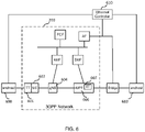
- FIG. 6 shows one possible example of network 200.
- network 200 is a 3GPP 5G network.
- FIG. 6 shows UE 202 connected to a 3GPP gNB 604, which is connected to a 5G User Plane Function (UPF) 606, which contains TT 607, and the 3GPP CN control plane entities: AMF, SMF, PCF and AF.
- the Ethernet network is being controlled by an Ethernet Controller 610, which may be a combination of a Centralized Network Configuration (CNC) and Centralized User Configuration (CUC).
- CNC Centralized Network Configuration
- CUC Centralized User Configuration
- a CNC is a component that configures network resources on behalf of TSN applications ("users").
- a CUC is a component that discovers end stations, retrieves end station capabilities and user requirements, and configures TSN features in end stations.
- the protocols that the CUC uses for communication with end stations are specific to the user application, not specified in this standard.
- a CUC exchanges information with a CNC in order to configure TSN features on behalf of its end stations.
- the 3GPP network may act as a bridge within the Ethernet network, and present an interface to the Ethernet Controller 610.
- the AF may take the role of interfacing with the Ethernet Controller from the 3GPP network side.
- the TT (TSN Translator) entity 607 in the UPF 606 and the TT 601 connected to (or in) the UE 202 may act to control jitter using the method described above.
- TT 607 may function as the ingress point for DL packets (e.g., packets address to end-host 690) and may function as the egress point for UL packets (e.g., packet addressed to end-host 680).
- DL packets e.g., packets address to end-host 690
- UL packets e.g., packet addressed to end-host 680
- One of the control plane entities may configure the ingress and egress points to implement the above described methods, respectively.
- the AF can signal to the TT 607 via the SMF and possibly also via the PCF.
- the AF can signal to the TT 601 via the SMF, AMF, gNB and UE. In this way, the AF can instruct both the TT 607 UPF and the TT 601 to start performing the method described herein.
- the TT 607 acts as the ingress point and the TT 601 acts as the egress point.
- the TT 601 side acts as the ingress point and the TT 607 acts as the egress point.
- the AF may provide to TT 601 and 607 the information needed to perform the above described methods (e.g., timing information, such as, for a given stream, the time slot spacing), and the AF may obtain this information from the Ethernet controller.
- the Ethernet controller after collecting information from the entire Ethernet network and knowing the stream requirements, instructs the AF about the timing requirements of the traffic streams going via the 3GPP domain (e.g., the time slot spacing). Based on the information received from the Ethernet controller, the AF configures the TT 601 and TT 607.
- FIG. 7 An example message flow diagram is shown in FIG. 7 . Note that there may be many variants of this message flow.
- the names of the messages are exemplary, and the messages may either use already existing standardized messages, or use newly defined messages.
- the Ethernet controller sends the timing requirements of the Ethernet streams, e.g. using the IEEE 802.1Qcc standard. That is, for example, Ethernet controller sends to the AF a Qcc configuration message (message 1). Based on this information, the AF decides to apply the solution of this invention for a certain set of streams.
- the Ethernet controller designs and knows the timing of packets belonging to a TSN Stream end-to-end in the TSN network (i.e., arrival time at each hop, leave time at each hop).
- the network 200 shown in FIG. 6 is a "hop" inside the TSN network.
- the Ethernet controller informs the network 200 (e.g., AF) with timing and stream related information.
- the AF uses the information to configure its internal functions to ensure requirements of the Stream.
- the timing information that the AF receives from the Ethernet Controller includes, for example: packet-arrival-time and inter-packet-time. Timing information is used to design the parameters of the stream specific slot-system inside the network 200 at both ingress and egress points. (Note: other information may be included, like packet-size (useful for bandwidth allocation), parameters to identify the stream (e.g., MAC addresses, VLAN-ID) etc. This other information can be used e.g., by gNB to optimize grant allocation on the air interface for the stream). 802.1Qcc is mentioned here, because it defines such parameters. Embodiments herein use the standard parameters.
- the AF uses the timing information received from Ethernet Controller to determine the parameters of the slot-system at ingress and egress points.
- the AF defines the following parameters for both ingress and egress point: (1) ingress slot-open-time, (2) egress slot-open-time, (3) slot-open-duration, (4) slot cycle and (5) slot-number.
- the difference between the ingress slot open time and the egress slot open time should be greater than worst case delay between the output of the ingress point (e.g., TT 607) and the input of the egress point (e.g.
- the slot-open-duration value informs the egress point and ingress point as to the time at which it may deactivate its slot counter.
- the AF After the AF defines the parameters, the AF transmits a number of TT configuration messages (e.g., TT configuration message 2, TT configuration message 4, and TT configuration message 6) as shown in FIG. 7 and described below
- TT configuration messages e.g., TT configuration message 2, TT configuration message 4, and TT configuration message 6
- TT configuration message 2 is transmitted via the SMF and UPF to TT 607.
- TT configuration message 2 includes the parameters for the uplink traffic egress side.
- the message is acknowledged (message 3).
- TT configuration message 4 is transmitted to TT 601 via AMF, gNB, and UE.
- TT configuration message 4 includes the parameters for the downlink traffic egress side, and the uplink traffic ingress side.
- the signaling is acknowledged (message 5).
- TT configuration message 4 sent to TT 601 includes: (2) egress slot-open-time, (3) slot-open-duration, (4) slot-cycle and (5) slot-number.
- the message may include other information as well (e.g., for stream identification; buffer size to allocate for the TSN stream; etc.).
- the AF may communicate with AMF and gNB to optimize RAN characteristics (e.g., grant allocation on air interface, etc.).
- TT configuration message 6 is transmitted to TT 607 via the SMF and the UPF.
- TT configuration message 6 includes the configuration for the downlink traffic ingress side.
- the signaling is acknowledged (message 7).
- TT configuration message includes: (1) ingress slot-open-time, (3) slot-open-duration, (4) slot-cycle and (5) slot-number. Other information may be included in the message as well.
- TT 607 confirms the configuration by transmitting an acknowledgment (message 7). At this point network 200 is now ready to receive and forward packets of the stream so that each packet of the stream will experience the same deterministic delay.
- FIG. 8 is a block diagram of an apparatus 801 for implementing an ingress point or an egress point (e.g., for implementing network node 206, UE 202, TT 601, TT 607), according to some embodiments. As shown in FIG.
- apparatus 801 may comprise: processing circuitry (PC) 802, which may include one or more processors (P) 855 (e.g., one or more general purpose microprocessors and/or one or more other processors, such as an application specific integrated circuit (ASIC), field-programmable gate arrays (FPGAs), and the like), which processors may be co-located in a single housing or in a single data center or may be geographically distributed; a first communications interface 848 comprising a transmitter (Tx) 845 and a receiver (Rx) 847 for enabling apparatus 801 to transmit data to and receive data from other nodes connected to a network 110 (e.g., an Internet Protocol (IP) network) to which interface 848 is connected; a second communications interface 850 comprising a transmitter (Tx) 851 and a receiver (Rx) 852 for enabling apparatus 801 to transmit data to and receive data from other nodes connected to a network 111 to which interface 850 is connected; and a local storage unit (a.k.a
- interface 850 may be coupled to an antenna enabling apparatus 801 to wirelessly transmit data to an access point (e.g., base station) within network 111.
- a computer program product (CPP) 841 may be provided.
- CPP 841 includes a computer readable medium (CRM) 842 storing a computer program (CP) 843 comprising computer readable instructions (CRI) 844.
- CRM 842 may be a non-transitory computer readable medium, such as, magnetic media (e.g., a hard disk), optical media, memory devices (e.g., random access memory, flash memory), and the like.
- the CRI 844 of computer program 843 is configured such that when executed by PC 802, the CRI causes apparatus 801 to perform steps described herein (e.g., steps described herein with reference to the flow charts).
- apparatus 801 may be configured to perform steps described herein without the need for code. That is, for example, PC 802 may consist merely of one or more ASICs.
- the features of the embodiments described herein may be implemented in hardware and/or software.
- FIG. 10A is a functional block diagram of an ingress point 1001 according to an embodiment.
- ingress point 1001 includes: packet modifying module 1002 configured to create a modified packet based on a received packet, wherein the modified packet includes the received packet and a slot identifier indicating a particular time slot in which the packet was received; and a transmit module 1004 configured to employ a transmitter to transmit the modified packet towards an egress point of the communication network.
- Modules 1002 and 1004 may be modules of computer program 843.
- FIG. 10B is a functional block diagram of an egress point 1010.
- ingress point 1010 includes: a packet receiving module 1012 configured to receive a packet that was transmitted by an ingress point of the communication network, wherein the received packet comprises a packet that was received at the ingress point and a slot identifier; a slot identifier determining module 1014 configured to determine the slot identifier included in the received packet; a packet storing module 1016 configured to store in a transmit buffer the received packet or a modified version of the received packet; a time slot determining module 1018 configured to determine, based on the slot identifier, a time at which to transmit the received or modified packet towards an end-host; and a transmit module 1020 configured to employ a transmitter to transmit the received or modified packet at the determined time.
- a packet receiving module 1012 configured to receive a packet that was transmitted by an ingress point of the communication network, wherein the received packet comprises a packet that was received at the ingress point and a slot identifier
Landscapes
- Engineering & Computer Science (AREA)
- Computer Networks & Wireless Communication (AREA)
- Signal Processing (AREA)
- Computer Security & Cryptography (AREA)
- Quality & Reliability (AREA)
- Databases & Information Systems (AREA)
- Data Exchanges In Wide-Area Networks (AREA)
Claims (15)
- Procédé (400) destiné à être utilisé pour éviter la gigue dans un réseau de communication (100), le procédé comprenant :par un point d'entrée (111, 112) du réseau de communication (100), la réception (s402) de paquets d'un flux de paquets, dans lequel les paquets doivent être distribués avec une latence fixe convenue et chacun d'eux doit être reçu au point d'entrée à un temps à l'intérieur d'un créneau de temps particulier ;par le point d'entrée, au cours d'au moins une période de temps, l'incrémentation d'une valeur de compteur de créneau toutes les T unités de temps, dans lequel T représente une quantité de temps entre des créneaux ;pour chacun des paquets reçus, la création (s404), par le point d'entrée, d'un paquet modifié qui inclut le paquet reçu et un identifiant de créneau indiquant le créneau de temps particulier dans lequel le paquet a été reçu, dans lequel l'identifiant de créneau est la valeur du compteur de créneau au temps auquel le point d'entrée a reçu le paquet ; etpar le point d'entrée, la transmission (s406) des paquets modifiés vers un point de sortie du réseau de communication, dans lequel le point d'entrée et le point de sortie partagent la même valeur de T pour l'incrémentation de la valeur de compteur de créneau.
- Procédé selon la revendication 1, dans lequel le point d'entrée crée le paquet modifié par l'ajout d'une étiquette au paquet, dans lequel l'étiquette comprend l'identifiant de créneau.
- Procédé selon la revendication 2, dans lequel le paquet reçu est une trame Ethernet et l'étiquette est une étiquette de redondance Ethernet, R-TAG.
- Procédé selon la revendication 3, dans lequel la R-TAG se compose de six octets et l'identifiant de créneau est contenu à l'intérieur des deux derniers octets de la R-TAG.
- Procédé (500) destiné à éviter la gigue dans un réseau de communication (100), le procédé comprenant :par un point de sortie (111, 112) du réseau de communication, la réception (s502) de paquets d'un flux de paquets qui ont été transmis par un point d'entrée du réseau de communication et qui doivent être distribués avec une latence fixe convenue, dans lequel les paquets reçus comprennent chacun un paquet qui a été reçu au point d'entrée et un identifiant de créneau indiquant un créneau de temps particulier dans lequel le paquet a été reçu par le point d'entrée ;par le point de sortie, au cours d'au moins une période de temps, l'incrémentation d'une valeur de compteur de créneau toutes les T unités de temps, dans lequel T représente une quantité de temps entre des créneaux, dans lequel l'identifiant de créneau est la valeur du compteur de créneau au temps auquel le point d'entrée a reçu le paquet et le point d'entrée et le point de sortie partagent la même valeur de T pour l'incrémentation de la valeur de compteur de créneau ;pour chacun des paquets reçus, la détermination (s504), par le point de sortie, de l'identifiant de créneau inclus dans le paquet reçu ;pour chacun des paquets reçus, le stockage (s506), par le point de sortie, dans une mémoire tampon de transmission, du paquet reçu ou d'une version modifiée du paquet reçu, la version modifiée étant générée par la suppression de l'identifiant de créneau du paquet reçu ;pour chacun des paquets reçus, la détermination (s508), par le point de sortie, sur la base de l'identifiant de créneau, d'un temps auquel transmettre le paquet reçu ou modifié vers un hôte d'extrémité ; etpour chacun des paquets reçus, la transmission (s510), par le point de sortie, du paquet reçu ou modifié au temps déterminé.
- Procédé selon la revendication 5, comprenant en outre, par le point de sortie, la suppression (s505) de l'identifiant de créneau du paquet reçu, en créant de ce fait la version modifiée, ladite version modifiée étant identique au paquet qui a été reçu au point d'entrée.
- Procédé selon la revendication 5 ou 6, dans lequel le paquet reçu comprend une étiquette qui contient l'identifiant de créneau.
- Procédé selon la revendication 7, dans lequel l'étape de la suppression de l'identifiant de créneau du paquet reçu comprend la suppression de l'étiquette du paquet reçu.
- Procédé selon l'une quelconque des revendications 5 à 8, comprenant en outre, par le point de sortie, l'initialisation de la valeur de compteur de créneau à une valeur initiale à un temps d'ouverture de créneau de sortie prédéterminé puis l'incrémentation de la valeur de compteur de créneau toutes les T unités de temps.
- Programme informatique (843) comprenant des instructions (844) qui, lorsqu'elles sont exécutées par une circuiterie de traitement (802), amènent la circuiterie de traitement à réaliser le procédé selon l'une quelconque des revendications 1 à 9.
- Point d'entrée (111, 112) d'un réseau de communication (100), le point d'entrée étant configuré pour :pour chacun de multiples paquets reçus d'un flux de paquets, qui doivent être distribués avec une latence fixe convenue, créer un paquet modifié sur la base du paquet reçu, dans lequel le paquet modifié inclut le paquet reçu et un identifiant de créneau indiquant un créneau de temps particulier dans lequel le paquet a été reçu ; etau cours d'au moins une période de temps, incrémenter une valeur de compteur de créneau toutes les T unités de temps, dans lequel T représente une quantité de temps entre des créneaux, dans lequel l'identifiant de créneau est la valeur du compteur de créneau au temps auquel le point d'entrée a reçu le paquet ;transmettre le paquet modifié vers un point de sortie du réseau de communication, dans lequel le point d'entrée et le point de sortie partagent la même valeur de T pour l'incrémentation de la valeur de compteur de créneau.
- Point d'entrée selon la revendication 11, dans lequel le point d'entrée est en outre apte à réaliser le procédé selon l'une quelconque des revendications 2 à 4.
- Point de sortie (111, 112) dans un réseau de communication (100), le point de sortie étant apte à :recevoir des paquets d'un flux de paquets qui ont été transmis par un point d'entrée du réseau de communication et qui doivent être distribués avec une latence fixe convenue, dans lequel les paquets reçus comprennent chacun un paquet qui a été reçu au point d'entrée et un identifiant de créneau ;au cours d'au moins une période de temps, incrémenter une valeur de compteur de créneau toutes les T unités de temps, dans lequel T représente une quantité de temps entre des créneaux, dans lequel l'identifiant de créneau est la valeur du compteur de créneau au temps auquel le point d'entrée a reçu le paquet et le point d'entrée et le point de sortie partagent la même valeur de T pour l'incrémentation de la valeur de compteur de créneau ;pour chacun des paquets reçus, déterminer l'identifiant de créneau inclus dans le paquet reçu ;pour chacun des paquets reçus, stocker, dans une mémoire tampon de transmission, le paquet reçu ou une version modifiée du paquet reçu, la version modifiée étant générée par la suppression de l'identifiant de créneau du paquet reçu ;pour chacun des paquets reçus, déterminer, sur la base de l'identifiant de créneau, un temps auquel transmettre le paquet reçu ou modifié vers un hôte d'extrémité ; etpour chacun des paquets reçus, transmettre le paquet reçu ou modifié au temps déterminé.
- Point de sortie selon la revendication 13, dans lequel le point de sortie est en outre apte à réaliser le procédé selon l'une quelconque des revendications 6 à 9.
- Appareil (801), l'appareil (801) comprenant :une circuiterie de traitement (802) ; etune mémoire (842), ladite mémoire contenant des instructions (844) exécutables par ladite circuiterie de traitement (802), de telle manière que ledit appareil soit opérationnel pour réaliser le procédé selon l'une quelconque des revendications 1 à 9.
Applications Claiming Priority (2)
| Application Number | Priority Date | Filing Date | Title |
|---|---|---|---|
| US201962853827P | 2019-05-29 | 2019-05-29 | |
| PCT/EP2020/060281 WO2020239313A1 (fr) | 2019-05-29 | 2020-04-09 | Évitement de gigue dans un système de communication |
Publications (2)
| Publication Number | Publication Date |
|---|---|
| EP3977692A1 EP3977692A1 (fr) | 2022-04-06 |
| EP3977692B1 true EP3977692B1 (fr) | 2022-10-12 |
Family
ID=70289773
Family Applications (1)
| Application Number | Title | Priority Date | Filing Date |
|---|---|---|---|
| EP20719384.8A Active EP3977692B1 (fr) | 2019-05-29 | 2020-04-09 | Éviter la gigue dans un système de communication |
Country Status (3)
| Country | Link |
|---|---|
| US (1) | US20220239600A1 (fr) |
| EP (1) | EP3977692B1 (fr) |
| WO (1) | WO2020239313A1 (fr) |
Families Citing this family (4)
| Publication number | Priority date | Publication date | Assignee | Title |
|---|---|---|---|---|
| EP3796723A1 (fr) * | 2019-09-17 | 2021-03-24 | Siemens Aktiengesellschaft | Procédé et dispositif de synchronisation en temps simple d'une communication dans un environnement industriel |
| CN114666809A (zh) * | 2020-12-23 | 2022-06-24 | 华为技术有限公司 | 数据发送的方法和装置 |
| US20240284257A1 (en) * | 2021-06-11 | 2024-08-22 | Telefonaktiebolaget Lm Ericsson (Publ) | Jitter Management |
| KR20230169378A (ko) * | 2021-07-15 | 2023-12-15 | 뉴 에이치3씨 테크놀로지스 코., 엘티디. | 메시지 전송 방법 및 디바이스 |
Family Cites Families (2)
| Publication number | Priority date | Publication date | Assignee | Title |
|---|---|---|---|---|
| US8228923B1 (en) * | 2008-01-09 | 2012-07-24 | Tellabs Operations, Inc. | Method and apparatus for measuring system latency using global time stamp |
| US8203961B2 (en) * | 2008-08-11 | 2012-06-19 | Qualcomm Incorporated | Methods and apparatus for providing modified timestamps in a communication system |
-
2020
- 2020-04-09 US US17/613,849 patent/US20220239600A1/en active Pending
- 2020-04-09 WO PCT/EP2020/060281 patent/WO2020239313A1/fr active Search and Examination
- 2020-04-09 EP EP20719384.8A patent/EP3977692B1/fr active Active
Also Published As
| Publication number | Publication date |
|---|---|
| US20220239600A1 (en) | 2022-07-28 |
| WO2020239313A1 (fr) | 2020-12-03 |
| EP3977692A1 (fr) | 2022-04-06 |
Similar Documents
| Publication | Publication Date | Title |
|---|---|---|
| EP3977692B1 (fr) | Éviter la gigue dans un système de communication | |
| US10594615B2 (en) | Method for controlling transmission of data | |
| EP3474519B1 (fr) | Procédé de changement divisé fonctionnel de réseau d'accès radio dynamique au moyen d'un réseautage défini par logiciel avec génération de paquet in-switch et traitement de flux dynamique | |
| US11765094B2 (en) | Communication system with de-jitter buffer for reducing jitter | |
| US10681128B2 (en) | Deterministic stream synchronization | |
| US20220021624A1 (en) | Output pacing in a cellular communications system serving as a time-sensitive networking (tsn) node | |
| EP2253106B1 (fr) | Procédé et système de contrôle de saturation de liaison de données synchrones dans des réseaux de paquets | |
| Bhattacharjee et al. | Time-sensitive networking for 5G fronthaul networks | |
| CN111357318A (zh) | 用于不同数据分组流之间的同步的方法和装置 | |
| CN110870285A (zh) | 在具有部分实时需求的数据网络中高性能数据传输的方法和执行该方法的装置 | |
| EP2777317B1 (fr) | Contrôle de congestion pour la communication de données multiflux | |
| WO2016208020A1 (fr) | Dispositif de communication, procédé de correction temporelle, et système de réseau | |
| EP3278518B1 (fr) | Noeud de réseau | |
| US12074809B2 (en) | Signalling of dejittering buffer capabilities for TSN integration | |
| US11742972B2 (en) | Method of guaranteeing jitter upper bound for a network without time-synchronization | |
| US20220294881A1 (en) | Industrial automation with cellular network | |
| Tardioli et al. | Pound: a ROS node for reducing delay and jitter in wireless multi-robot networks | |
| EP3403436B1 (fr) | Procédé et noeud de réseau pour gérer des signaux émis par des dispositifs sans fil | |
| US11924740B2 (en) | Signal transfer system, signal transfer device, route control device and signal transfer method | |
| WO2023067800A1 (fr) | Dispositif de commande, système de communication, procédé de commande et programme associé | |
| JP2014112886A (ja) | 通信ネットワークにおける輻輳処理 |
Legal Events
| Date | Code | Title | Description |
|---|---|---|---|
| STAA | Information on the status of an ep patent application or granted ep patent |
Free format text: STATUS: UNKNOWN |
|
| STAA | Information on the status of an ep patent application or granted ep patent |
Free format text: STATUS: THE INTERNATIONAL PUBLICATION HAS BEEN MADE |
|
| PUAI | Public reference made under article 153(3) epc to a published international application that has entered the european phase |
Free format text: ORIGINAL CODE: 0009012 |
|
| STAA | Information on the status of an ep patent application or granted ep patent |
Free format text: STATUS: REQUEST FOR EXAMINATION WAS MADE |
|
| 17P | Request for examination filed |
Effective date: 20211105 |
|
| AK | Designated contracting states |
Kind code of ref document: A1 Designated state(s): AL AT BE BG CH CY CZ DE DK EE ES FI FR GB GR HR HU IE IS IT LI LT LU LV MC MK MT NL NO PL PT RO RS SE SI SK SM TR |
|
| REG | Reference to a national code |
Ref country code: DE Ref legal event code: R079 Ref document number: 602020005626 Country of ref document: DE Free format text: PREVIOUS MAIN CLASS: H04L0012857000 Ipc: H04L0047249100 |
|
| GRAP | Despatch of communication of intention to grant a patent |
Free format text: ORIGINAL CODE: EPIDOSNIGR1 |
|
| STAA | Information on the status of an ep patent application or granted ep patent |
Free format text: STATUS: GRANT OF PATENT IS INTENDED |
|
| RIC1 | Information provided on ipc code assigned before grant |
Ipc: H04W 8/04 20090101ALI20220613BHEP Ipc: H04L 47/32 20220101ALI20220613BHEP Ipc: H04L 47/283 20220101ALI20220613BHEP Ipc: H04L 47/2416 20220101ALI20220613BHEP Ipc: H04L 69/28 20220101ALI20220613BHEP Ipc: H04L 47/70 20220101ALI20220613BHEP Ipc: H04L 47/56 20220101ALI20220613BHEP Ipc: H04L 47/2491 20220101AFI20220613BHEP |
|
| INTG | Intention to grant announced |
Effective date: 20220705 |
|
| GRAS | Grant fee paid |
Free format text: ORIGINAL CODE: EPIDOSNIGR3 |
|
| DAV | Request for validation of the european patent (deleted) | ||
| DAX | Request for extension of the european patent (deleted) | ||
| GRAA | (expected) grant |
Free format text: ORIGINAL CODE: 0009210 |
|
| STAA | Information on the status of an ep patent application or granted ep patent |
Free format text: STATUS: THE PATENT HAS BEEN GRANTED |
|
| AK | Designated contracting states |
Kind code of ref document: B1 Designated state(s): AL AT BE BG CH CY CZ DE DK EE ES FI FR GB GR HR HU IE IS IT LI LT LU LV MC MK MT NL NO PL PT RO RS SE SI SK SM TR |
|
| REG | Reference to a national code |
Ref country code: GB Ref legal event code: FG4D |
|
| REG | Reference to a national code |
Ref country code: CH Ref legal event code: EP |
|
| REG | Reference to a national code |
Ref country code: DE Ref legal event code: R096 Ref document number: 602020005626 Country of ref document: DE |
|
| REG | Reference to a national code |
Ref country code: IE Ref legal event code: FG4D |
|
| REG | Reference to a national code |
Ref country code: AT Ref legal event code: REF Ref document number: 1524850 Country of ref document: AT Kind code of ref document: T Effective date: 20221115 |
|
| REG | Reference to a national code |
Ref country code: LT Ref legal event code: MG9D |
|
| REG | Reference to a national code |
Ref country code: NL Ref legal event code: MP Effective date: 20221012 |
|
| REG | Reference to a national code |
Ref country code: AT Ref legal event code: MK05 Ref document number: 1524850 Country of ref document: AT Kind code of ref document: T Effective date: 20221012 |
|
| PG25 | Lapsed in a contracting state [announced via postgrant information from national office to epo] |
Ref country code: NL Free format text: LAPSE BECAUSE OF FAILURE TO SUBMIT A TRANSLATION OF THE DESCRIPTION OR TO PAY THE FEE WITHIN THE PRESCRIBED TIME-LIMIT Effective date: 20221012 |
|
| PG25 | Lapsed in a contracting state [announced via postgrant information from national office to epo] |
Ref country code: SE Free format text: LAPSE BECAUSE OF FAILURE TO SUBMIT A TRANSLATION OF THE DESCRIPTION OR TO PAY THE FEE WITHIN THE PRESCRIBED TIME-LIMIT Effective date: 20221012 Ref country code: PT Free format text: LAPSE BECAUSE OF FAILURE TO SUBMIT A TRANSLATION OF THE DESCRIPTION OR TO PAY THE FEE WITHIN THE PRESCRIBED TIME-LIMIT Effective date: 20230213 Ref country code: NO Free format text: LAPSE BECAUSE OF FAILURE TO SUBMIT A TRANSLATION OF THE DESCRIPTION OR TO PAY THE FEE WITHIN THE PRESCRIBED TIME-LIMIT Effective date: 20230112 Ref country code: LT Free format text: LAPSE BECAUSE OF FAILURE TO SUBMIT A TRANSLATION OF THE DESCRIPTION OR TO PAY THE FEE WITHIN THE PRESCRIBED TIME-LIMIT Effective date: 20221012 Ref country code: FI Free format text: LAPSE BECAUSE OF FAILURE TO SUBMIT A TRANSLATION OF THE DESCRIPTION OR TO PAY THE FEE WITHIN THE PRESCRIBED TIME-LIMIT Effective date: 20221012 Ref country code: ES Free format text: LAPSE BECAUSE OF FAILURE TO SUBMIT A TRANSLATION OF THE DESCRIPTION OR TO PAY THE FEE WITHIN THE PRESCRIBED TIME-LIMIT Effective date: 20221012 Ref country code: AT Free format text: LAPSE BECAUSE OF FAILURE TO SUBMIT A TRANSLATION OF THE DESCRIPTION OR TO PAY THE FEE WITHIN THE PRESCRIBED TIME-LIMIT Effective date: 20221012 |
|
| PG25 | Lapsed in a contracting state [announced via postgrant information from national office to epo] |
Ref country code: RS Free format text: LAPSE BECAUSE OF FAILURE TO SUBMIT A TRANSLATION OF THE DESCRIPTION OR TO PAY THE FEE WITHIN THE PRESCRIBED TIME-LIMIT Effective date: 20221012 Ref country code: PL Free format text: LAPSE BECAUSE OF FAILURE TO SUBMIT A TRANSLATION OF THE DESCRIPTION OR TO PAY THE FEE WITHIN THE PRESCRIBED TIME-LIMIT Effective date: 20221012 Ref country code: LV Free format text: LAPSE BECAUSE OF FAILURE TO SUBMIT A TRANSLATION OF THE DESCRIPTION OR TO PAY THE FEE WITHIN THE PRESCRIBED TIME-LIMIT Effective date: 20221012 Ref country code: IS Free format text: LAPSE BECAUSE OF FAILURE TO SUBMIT A TRANSLATION OF THE DESCRIPTION OR TO PAY THE FEE WITHIN THE PRESCRIBED TIME-LIMIT Effective date: 20230212 Ref country code: HR Free format text: LAPSE BECAUSE OF FAILURE TO SUBMIT A TRANSLATION OF THE DESCRIPTION OR TO PAY THE FEE WITHIN THE PRESCRIBED TIME-LIMIT Effective date: 20221012 Ref country code: GR Free format text: LAPSE BECAUSE OF FAILURE TO SUBMIT A TRANSLATION OF THE DESCRIPTION OR TO PAY THE FEE WITHIN THE PRESCRIBED TIME-LIMIT Effective date: 20230113 |
|
| REG | Reference to a national code |
Ref country code: DE Ref legal event code: R097 Ref document number: 602020005626 Country of ref document: DE |
|
| PG25 | Lapsed in a contracting state [announced via postgrant information from national office to epo] |
Ref country code: SM Free format text: LAPSE BECAUSE OF FAILURE TO SUBMIT A TRANSLATION OF THE DESCRIPTION OR TO PAY THE FEE WITHIN THE PRESCRIBED TIME-LIMIT Effective date: 20221012 Ref country code: RO Free format text: LAPSE BECAUSE OF FAILURE TO SUBMIT A TRANSLATION OF THE DESCRIPTION OR TO PAY THE FEE WITHIN THE PRESCRIBED TIME-LIMIT Effective date: 20221012 Ref country code: EE Free format text: LAPSE BECAUSE OF FAILURE TO SUBMIT A TRANSLATION OF THE DESCRIPTION OR TO PAY THE FEE WITHIN THE PRESCRIBED TIME-LIMIT Effective date: 20221012 Ref country code: DK Free format text: LAPSE BECAUSE OF FAILURE TO SUBMIT A TRANSLATION OF THE DESCRIPTION OR TO PAY THE FEE WITHIN THE PRESCRIBED TIME-LIMIT Effective date: 20221012 Ref country code: CZ Free format text: LAPSE BECAUSE OF FAILURE TO SUBMIT A TRANSLATION OF THE DESCRIPTION OR TO PAY THE FEE WITHIN THE PRESCRIBED TIME-LIMIT Effective date: 20221012 |
|
| PLBE | No opposition filed within time limit |
Free format text: ORIGINAL CODE: 0009261 |
|
| STAA | Information on the status of an ep patent application or granted ep patent |
Free format text: STATUS: NO OPPOSITION FILED WITHIN TIME LIMIT |
|
| PG25 | Lapsed in a contracting state [announced via postgrant information from national office to epo] |
Ref country code: SK Free format text: LAPSE BECAUSE OF FAILURE TO SUBMIT A TRANSLATION OF THE DESCRIPTION OR TO PAY THE FEE WITHIN THE PRESCRIBED TIME-LIMIT Effective date: 20221012 Ref country code: AL Free format text: LAPSE BECAUSE OF FAILURE TO SUBMIT A TRANSLATION OF THE DESCRIPTION OR TO PAY THE FEE WITHIN THE PRESCRIBED TIME-LIMIT Effective date: 20221012 |
|
| 26N | No opposition filed |
Effective date: 20230713 |
|
| PG25 | Lapsed in a contracting state [announced via postgrant information from national office to epo] |
Ref country code: SI Free format text: LAPSE BECAUSE OF FAILURE TO SUBMIT A TRANSLATION OF THE DESCRIPTION OR TO PAY THE FEE WITHIN THE PRESCRIBED TIME-LIMIT Effective date: 20221012 |
|
| REG | Reference to a national code |
Ref country code: CH Ref legal event code: PL |
|
| PG25 | Lapsed in a contracting state [announced via postgrant information from national office to epo] |
Ref country code: LU Free format text: LAPSE BECAUSE OF NON-PAYMENT OF DUE FEES Effective date: 20230409 |
|
| REG | Reference to a national code |
Ref country code: BE Ref legal event code: MM Effective date: 20230430 |
|
| PG25 | Lapsed in a contracting state [announced via postgrant information from national office to epo] |
Ref country code: MC Free format text: LAPSE BECAUSE OF FAILURE TO SUBMIT A TRANSLATION OF THE DESCRIPTION OR TO PAY THE FEE WITHIN THE PRESCRIBED TIME-LIMIT Effective date: 20221012 |
|
| PG25 | Lapsed in a contracting state [announced via postgrant information from national office to epo] |
Ref country code: MC Free format text: LAPSE BECAUSE OF FAILURE TO SUBMIT A TRANSLATION OF THE DESCRIPTION OR TO PAY THE FEE WITHIN THE PRESCRIBED TIME-LIMIT Effective date: 20221012 Ref country code: LI Free format text: LAPSE BECAUSE OF NON-PAYMENT OF DUE FEES Effective date: 20230430 Ref country code: FR Free format text: LAPSE BECAUSE OF NON-PAYMENT OF DUE FEES Effective date: 20230430 Ref country code: CH Free format text: LAPSE BECAUSE OF NON-PAYMENT OF DUE FEES Effective date: 20230430 |
|
| REG | Reference to a national code |
Ref country code: IE Ref legal event code: MM4A |
|
| PG25 | Lapsed in a contracting state [announced via postgrant information from national office to epo] |
Ref country code: BE Free format text: LAPSE BECAUSE OF NON-PAYMENT OF DUE FEES Effective date: 20230430 |
|
| PG25 | Lapsed in a contracting state [announced via postgrant information from national office to epo] |
Ref country code: IE Free format text: LAPSE BECAUSE OF NON-PAYMENT OF DUE FEES Effective date: 20230409 |
|
| PG25 | Lapsed in a contracting state [announced via postgrant information from national office to epo] |
Ref country code: IE Free format text: LAPSE BECAUSE OF NON-PAYMENT OF DUE FEES Effective date: 20230409 |
|
| PG25 | Lapsed in a contracting state [announced via postgrant information from national office to epo] |
Ref country code: IT Free format text: LAPSE BECAUSE OF FAILURE TO SUBMIT A TRANSLATION OF THE DESCRIPTION OR TO PAY THE FEE WITHIN THE PRESCRIBED TIME-LIMIT Effective date: 20221012 |
|
| PGFP | Annual fee paid to national office [announced via postgrant information from national office to epo] |
Ref country code: GB Payment date: 20240429 Year of fee payment: 5 |
|
| PGFP | Annual fee paid to national office [announced via postgrant information from national office to epo] |
Ref country code: DE Payment date: 20240429 Year of fee payment: 5 |