EP3977185B1 - Polarization-maintaining highly elliptical core fiber with stress-induced birefringence - Google Patents
Polarization-maintaining highly elliptical core fiber with stress-induced birefringence Download PDFInfo
- Publication number
- EP3977185B1 EP3977185B1 EP20847919.6A EP20847919A EP3977185B1 EP 3977185 B1 EP3977185 B1 EP 3977185B1 EP 20847919 A EP20847919 A EP 20847919A EP 3977185 B1 EP3977185 B1 EP 3977185B1
- Authority
- EP
- European Patent Office
- Prior art keywords
- core
- optical fiber
- axis
- cladding
- elliptical
- Prior art date
- Legal status (The legal status is an assumption and is not a legal conclusion. Google has not performed a legal analysis and makes no representation as to the accuracy of the status listed.)
- Active
Links
Images


Classifications
-
- H—ELECTRICITY
- H01—ELECTRIC ELEMENTS
- H01S—DEVICES USING THE PROCESS OF LIGHT AMPLIFICATION BY STIMULATED EMISSION OF RADIATION [LASER] TO AMPLIFY OR GENERATE LIGHT; DEVICES USING STIMULATED EMISSION OF ELECTROMAGNETIC RADIATION IN WAVE RANGES OTHER THAN OPTICAL
- H01S3/00—Lasers, i.e. devices using stimulated emission of electromagnetic radiation in the infrared, visible or ultraviolet wave range
- H01S3/05—Construction or shape of optical resonators; Accommodation of active medium therein; Shape of active medium
- H01S3/06—Construction or shape of active medium
- H01S3/063—Waveguide lasers, i.e. whereby the dimensions of the waveguide are of the order of the light wavelength
- H01S3/067—Fibre lasers
- H01S3/06708—Constructional details of the fibre, e.g. compositions, cross-section, shape or tapering
- H01S3/06729—Peculiar transverse fibre profile
-
- H—ELECTRICITY
- H01—ELECTRIC ELEMENTS
- H01S—DEVICES USING THE PROCESS OF LIGHT AMPLIFICATION BY STIMULATED EMISSION OF RADIATION [LASER] TO AMPLIFY OR GENERATE LIGHT; DEVICES USING STIMULATED EMISSION OF ELECTROMAGNETIC RADIATION IN WAVE RANGES OTHER THAN OPTICAL
- H01S3/00—Lasers, i.e. devices using stimulated emission of electromagnetic radiation in the infrared, visible or ultraviolet wave range
- H01S3/05—Construction or shape of optical resonators; Accommodation of active medium therein; Shape of active medium
- H01S3/06—Construction or shape of active medium
- H01S3/063—Waveguide lasers, i.e. whereby the dimensions of the waveguide are of the order of the light wavelength
- H01S3/067—Fibre lasers
- H01S3/06708—Constructional details of the fibre, e.g. compositions, cross-section, shape or tapering
- H01S3/06712—Polarising fibre; Polariser
-
- H—ELECTRICITY
- H01—ELECTRIC ELEMENTS
- H01S—DEVICES USING THE PROCESS OF LIGHT AMPLIFICATION BY STIMULATED EMISSION OF RADIATION [LASER] TO AMPLIFY OR GENERATE LIGHT; DEVICES USING STIMULATED EMISSION OF ELECTROMAGNETIC RADIATION IN WAVE RANGES OTHER THAN OPTICAL
- H01S3/00—Lasers, i.e. devices using stimulated emission of electromagnetic radiation in the infrared, visible or ultraviolet wave range
- H01S3/05—Construction or shape of optical resonators; Accommodation of active medium therein; Shape of active medium
- H01S3/06—Construction or shape of active medium
- H01S3/063—Waveguide lasers, i.e. whereby the dimensions of the waveguide are of the order of the light wavelength
- H01S3/067—Fibre lasers
- H01S3/06708—Constructional details of the fibre, e.g. compositions, cross-section, shape or tapering
- H01S3/06716—Fibre compositions or doping with active elements
-
- H—ELECTRICITY
- H01—ELECTRIC ELEMENTS
- H01S—DEVICES USING THE PROCESS OF LIGHT AMPLIFICATION BY STIMULATED EMISSION OF RADIATION [LASER] TO AMPLIFY OR GENERATE LIGHT; DEVICES USING STIMULATED EMISSION OF ELECTROMAGNETIC RADIATION IN WAVE RANGES OTHER THAN OPTICAL
- H01S3/00—Lasers, i.e. devices using stimulated emission of electromagnetic radiation in the infrared, visible or ultraviolet wave range
- H01S3/05—Construction or shape of optical resonators; Accommodation of active medium therein; Shape of active medium
- H01S3/06—Construction or shape of active medium
- H01S3/063—Waveguide lasers, i.e. whereby the dimensions of the waveguide are of the order of the light wavelength
- H01S3/067—Fibre lasers
- H01S3/06754—Fibre amplifiers
-
- H—ELECTRICITY
- H01—ELECTRIC ELEMENTS
- H01S—DEVICES USING THE PROCESS OF LIGHT AMPLIFICATION BY STIMULATED EMISSION OF RADIATION [LASER] TO AMPLIFY OR GENERATE LIGHT; DEVICES USING STIMULATED EMISSION OF ELECTROMAGNETIC RADIATION IN WAVE RANGES OTHER THAN OPTICAL
- H01S3/00—Lasers, i.e. devices using stimulated emission of electromagnetic radiation in the infrared, visible or ultraviolet wave range
- H01S3/14—Lasers, i.e. devices using stimulated emission of electromagnetic radiation in the infrared, visible or ultraviolet wave range characterised by the material used as the active medium
- H01S3/16—Solid materials
- H01S3/1601—Solid materials characterised by an active (lasing) ion
- H01S3/1603—Solid materials characterised by an active (lasing) ion rare earth
- H01S3/1608—Solid materials characterised by an active (lasing) ion rare earth erbium
-
- H—ELECTRICITY
- H04—ELECTRIC COMMUNICATION TECHNIQUE
- H04J—MULTIPLEX COMMUNICATION
- H04J14/00—Optical multiplex systems
- H04J14/04—Mode multiplex systems
-
- G—PHYSICS
- G02—OPTICS
- G02B—OPTICAL ELEMENTS, SYSTEMS OR APPARATUS
- G02B6/00—Light guides; Structural details of arrangements comprising light guides and other optical elements, e.g. couplings
- G02B6/02—Optical fibres with cladding with or without a coating
- G02B6/02214—Optical fibres with cladding with or without a coating tailored to obtain the desired dispersion, e.g. dispersion shifted, dispersion flattened
- G02B6/02285—Characterised by the polarisation mode dispersion [PMD] properties, e.g. for minimising PMD
-
- G—PHYSICS
- G02—OPTICS
- G02B—OPTICAL ELEMENTS, SYSTEMS OR APPARATUS
- G02B6/00—Light guides; Structural details of arrangements comprising light guides and other optical elements, e.g. couplings
- G02B6/02—Optical fibres with cladding with or without a coating
- G02B6/024—Optical fibres with cladding with or without a coating with polarisation maintaining properties
-
- G—PHYSICS
- G02—OPTICS
- G02B—OPTICAL ELEMENTS, SYSTEMS OR APPARATUS
- G02B6/00—Light guides; Structural details of arrangements comprising light guides and other optical elements, e.g. couplings
- G02B6/02—Optical fibres with cladding with or without a coating
- G02B6/036—Optical fibres with cladding with or without a coating core or cladding comprising multiple layers
- G02B6/03616—Optical fibres characterised both by the number of different refractive index layers around the central core segment, i.e. around the innermost high index core layer, and their relative refractive index difference
- G02B6/03622—Optical fibres characterised both by the number of different refractive index layers around the central core segment, i.e. around the innermost high index core layer, and their relative refractive index difference having 2 layers only
- G02B6/03627—Optical fibres characterised both by the number of different refractive index layers around the central core segment, i.e. around the innermost high index core layer, and their relative refractive index difference having 2 layers only arranged - +
-
- H—ELECTRICITY
- H01—ELECTRIC ELEMENTS
- H01S—DEVICES USING THE PROCESS OF LIGHT AMPLIFICATION BY STIMULATED EMISSION OF RADIATION [LASER] TO AMPLIFY OR GENERATE LIGHT; DEVICES USING STIMULATED EMISSION OF ELECTROMAGNETIC RADIATION IN WAVE RANGES OTHER THAN OPTICAL
- H01S3/00—Lasers, i.e. devices using stimulated emission of electromagnetic radiation in the infrared, visible or ultraviolet wave range
- H01S3/09—Processes or apparatus for excitation, e.g. pumping
- H01S3/091—Processes or apparatus for excitation, e.g. pumping using optical pumping
- H01S3/094—Processes or apparatus for excitation, e.g. pumping using optical pumping by coherent light
- H01S3/094003—Processes or apparatus for excitation, e.g. pumping using optical pumping by coherent light the pumped medium being a fibre
- H01S3/094011—Processes or apparatus for excitation, e.g. pumping using optical pumping by coherent light the pumped medium being a fibre with bidirectional pumping, i.e. with injection of the pump light from both two ends of the fibre
-
- H—ELECTRICITY
- H01—ELECTRIC ELEMENTS
- H01S—DEVICES USING THE PROCESS OF LIGHT AMPLIFICATION BY STIMULATED EMISSION OF RADIATION [LASER] TO AMPLIFY OR GENERATE LIGHT; DEVICES USING STIMULATED EMISSION OF ELECTROMAGNETIC RADIATION IN WAVE RANGES OTHER THAN OPTICAL
- H01S3/00—Lasers, i.e. devices using stimulated emission of electromagnetic radiation in the infrared, visible or ultraviolet wave range
- H01S3/09—Processes or apparatus for excitation, e.g. pumping
- H01S3/091—Processes or apparatus for excitation, e.g. pumping using optical pumping
- H01S3/094—Processes or apparatus for excitation, e.g. pumping using optical pumping by coherent light
- H01S3/0941—Processes or apparatus for excitation, e.g. pumping using optical pumping by coherent light of a laser diode
- H01S3/09415—Processes or apparatus for excitation, e.g. pumping using optical pumping by coherent light of a laser diode the pumping beam being parallel to the lasing mode of the pumped medium, e.g. end-pumping
Definitions
- the present invention pertains to the field of fiber optic communications and in particular to an elliptical core optical fiber.
- MDM Mode division multiplexing
- FMFs few-mode fibers
- MIMO multiple-input multiple-output
- DSP digital signal processing
- PM FMF polarization-maintaining
- the document BO-HUN CHOI ET AL "New pump wavelength of 1540-nm band for long-wavelength-band erbium-doped fiber amplifier (I-band EDFA)", XP 011101713 shows a regular erbium-doped fiber with a circular core.
- the document WANG LI CHAN ET AL "Linearly polarized vector modes: enabling MIMO free mode division multiplexing", XP 055931078 shows an optical fiber with an elliptical ring-core fiber.
- An object of embodiments of the present invention is to provide an improved optical fiber for use in an MDM communications system.
- An aspect of the invention as defined by independent claim 1 includes an optical fiber including a core having an elliptical cross section and an ellipticity between 2 and 40.
- the optical fiber also includes a cladding having a circular cross section, with the cladding enclosing the core.
- An aspect of the disclosure includes the core and the cladding having a common central axis.
- An aspect of the disclosure includes an optical fiber wherein a difference of a refractive index of the cladding to a refractive index of the core is between 1 x 10 2 and 1.5 x 10 -1 .
- An aspect of the disclosure includes an optical fiber wherein a ratio of a refractive index of the cladding to a refractive index of the core is between 1 x 10 -2 and 1.5 x 10 -1 .
- An aspect of the disclosure includes an optical fiber comprises a trench located between the core and the cladding.
- the trench has a uniform width and encircles the core.
- the refractive index of the trench is lower than the refractive index of the cladding.
- An aspect of the disclosure includes an optical fiber wherein a width of the core along a y-axis allows for single mode transmission.
- An aspect of the invention as defined by independent claim 1 includes an optical fiber wherein a width of the core along an x-axis allows for the transmission of a plurality of mode pairs.
- An aspect of the invention as defined by independent claim 1 includes an optical fiber wherein each of the plurality of mode pairs have two orthogonal linear polarizations.
- An aspect of the invention as defined by independent claim 1 includes an optical fiber wherein the plurality of mode pairs have an effective index separation between the adjacent vector modes greater than 1 x 10 -4 .
- An aspect of the invention as defined by independent claim 1 includes an optical fiber wherein the effective index separation is caused by thermal stress induced during the manufacture of the optical fiber and the elliptical shape of the core.
- An aspect of the disclosure includes an optical fiber wherein the core is doped with rare earth ions.
- An aspect of the disclosure includes an optical fiber amplifier (OFA) including a first WDM coupler receiving an input signal and an output from a first pump optical source.
- An optical fiber receiving an output from the first WDM coupler.
- the optical fiber includes a core having an elliptical cross section having an ellipticity between 2 and 40.
- the optical fiber also includes a cladding, having a circular cross section, enclosing the core.
- the OFA also includes a second WDM coupler receiving the output of the optical fiber and an output of a second pump optical source. The second WDM coupler outputs an amplified optical signal.
- An aspect of the disclosure includes an OFA wherein the core and the cladding have a common central axis.
- An aspect of the disclosure includes an OFA wherein the core is doped with rare earth ions.
- An aspect of the disclosure includes an OFA wherein the optical fiber includes a trench located between the core and the cladding.
- the trench has a uniform width and encircles the core.
- the refractive index of the trench is lower than the refractive index of the cladding.
- An aspect of the disclosure includes an OFA wherein a width of the core along a y-axis allows for single mode transmission and a width of the core along an x-axis allows for the transmission of a plurality of mode pairs.
- An aspect of the disclosure includes a method for manufacturing an optical fiber as disclosed in independent claim 8.
- the method includes preparing a cylindrical preform having a cross section comprising an inner core and an outer cladding.
- the inner core has a circular profile. Cutting two opposing sides of the cylindrical preform along a length of the cylindrical preform to produce a cut preform with opposing parallel surfaces along a longitudinal axis of the cut preform. Heating the cut preform until the cut preform has a circular profile and an inner core of the cut preform has an elliptical profile. Pulling the cut preform to form the optical fiber having a core with an elliptical profile.
- the core has an ellipticity between 2 and 40, and a cladding has a circular cross section, with the core being enclosed by the cladding.
- An aspect of the disclosure includes the core and the cladding have a common central axis.
- An aspect of the disclosure includes a trench portion situated between the core and the cladding.
- the trench portion is present in the optical fiber and isolates the core from the cladding.
- An aspect of the disclosure includes a cylindrical preform that is fabricated using a modified chemical vapor deposition (MCVD) process.
- MCVD modified chemical vapor deposition
- the preform further includes a trench portion situated between the core and the cladding.
- the trench portion is present in the optical fiber and isolates the core from the cladding.
- the elliptical profile is formed due to surface tension and the flow of material during the heating.
- Embodiments have been described above in conjunctions with aspects of the present invention upon which they can be implemented. Those skilled in the art will appreciate that embodiments may be implemented in conjunction with the aspect with which they are described but may also be implemented with other embodiments of that aspect. When embodiments are mutually exclusive, or are otherwise incompatible with each other, it will be apparent to those skilled in the art. Some embodiments may be described in relation to one aspect, but may also be applicable to other aspects, as will be apparent to those of skill in the art.
- FIG. 1 illustrates a cross-section view of a highly elliptical core fiber (HECF) 100 according to a first embodiment of the invention.
- the optical fiber comprises a cladding 102, which is typically the industry standard, 125 ⁇ m in diameter.
- a solid core 104 At the center of the fiber is a solid core 104 surrounded by a trench 106.
- the cladding is further surrounded by a buffer, which is in turn covered by a jacket as is known in the art.
- the cross-section profile of the core 104 is elliptical in shape.
- the core's cross section 104 has an x-axis 110 and a y-axis 108.
- the core 104 has approximate cross-sectional dimensions of 38.5 ⁇ m 202 along the x-axis 110 and 6.1 ⁇ m along the y-axis 108.
- the dimension of the x-axis 110 is selected to allow for multiple spatial modes to be distributed in a one-dimensional array in the x-axis 110.
- the ellipticity, ⁇ of the core, defined as the ratio of the cross-sectional length in the x-direction to the cross-sectional length in the y-direction, is between 2 and 40.
- the x-axis 110 may also be referred to as the major axis of the elliptical core, while the y-axis 108 may be referred to as the minor axis of the elliptical core. Rotation of the fiber so that the major axis is no longer horizontal should not be considered to be changing the alignment of the X and Y axes.
- the ellipticity, ⁇ may also be considered as the ratio of the width of the core along the x-axis 110 to the width of the core along the y-axis 108.
- the core 104 may be thought of as elliptic cylinder, such that the length of the x-axis 110 is greater than the length of the y-axis and therefore, the x-axis 110 forms the major axis of the ellipse and the y-axis 108 forms the minor axis of the ellipse.
- the x-axis 110 and the y-axis 108 intersect at a right angle and the intersection of the x-axis 110 and the y-axis 108 defines the center of the elliptical cross-section.
- the core 104 has the shape of an elliptic cylinder with a central axis, also known as a longitudinal axis, running through the center of each elliptical cross-section of the core 104.
- the cladding 102 may be viewed as having a circular cross section with a center and has a cylindrical shape with a central axis running through the center of each circular cross-section of the cladding 102.
- the core 104 and the cladding 102 have a common central axis, such that the core 104 is centered within the cladding 102. Accordingly, the HECF is formed so that the cladding 102 and the core 104 share a common central axis.
- Optical fiber is manufactured using a silica glass material comprised mainly of SiO 2 and the cladding 102 is comprised of a substantially pure silica glass material.
- the core 104 is manufactured by doping the SiO 2 material with GeO 2 .
- the core 104 is comprised of SiO 2 doped with 7.3 mol% of GeO 2 .
- the trench 106 surrounds the core 104 and, in some embodiments is approximately 4.7 ⁇ m wide 206.
- the trench is made of SiO 2 doped with F, fluorine. In some embodiments the trench is doped with 2 mol% of F.
- the bending loss experienced by the HECF increases as the ellipticity increases, however the trench serves to reduce the bending loss of higher-order modes in the optical fiber.
- FIG. 2 shows the refractive index profile along the x-axis 110 for the optical fiber 100.
- the core 104, trench 106, and cladding 102 have differing refractive indexes determined by their respective materials.
- the difference in refractive index between the core 104 and cladding 102, ⁇ n 204 is approximately 1.1 ⁇ 10 -2 .
- the refractive index difference between the core 104 and the cladding 102 is within the range 1 ⁇ 10 -2 ⁇ ⁇ n ⁇ 1.5 ⁇ 10 -1 .
- the difference in refractive index between the trench 106 and the cladding 102, - ⁇ n trench 208 is approximately 5.7 ⁇ 10 -3 .
- the geometry of the highly elliptical core leads to geometry-enhanced birefringence in the optical fiber.
- This source of birefringence is related to the geometric structure of the core, where a higher core ellipticity will cause a higher value of birefringence.
- inconstant, compressive thermal stress 302 is induced into the core 104, mainly along the y-axis 108 direction.
- the fiber becomes stressed due to different thermal expansion coefficients of the core 104 and the cladding layers 102.
- Different amounts of stress are applied along long, x-axis 110 and short, y-axis 108 due to the asymmetry of its core structure.
- the isotropic glass starts to become anisotropic, with a consequent change of the refractive indices along the principal, x and y stress directions.
- the thermal stress has the effect to increase the effective index difference ( ⁇ n eff ) between the two polarizations of the same spatial mode.
- Optical fiber according to an embodiment of the invention may transmit data on five spatial mode groups with two-fold polarization degeneracy to obtain ten MDM channels.
- the supported modes are labeled as TE 1n and TM 1N , depending on the polarization state (respectively along the x-axis or the y-axis).
- the subscript "1" indicates the single mode operation along the short-axis (y-axis), while “n” is an integer indicating the number of the dark lines of the mode profile along the long-axis (x-axis).
- the elliptical shape of the core combined with thermal stress created during manufacturing produces a relatively large birefringence so that the modal effective index separation, ⁇ n eff is greater than 1 x 10 -4 . This reduces the mode coupling inside the HECF so that the fiber modes can propagate without significant crosstalk up to a fiber length of approximately 1 km. This allows for transmission systems to be designed that do not require MIMO DSPs.
- the core may be doped with rare earth ions such as erbium and/or ytterbium in order to produce an optical active fiber.
- FIG. 4 illustrates an optical fiber 400 according to another embodiment with an alternative structure.
- this embodiment comprised a cladding 102 and core 104, but lacks a trench 106 between the core and cladding.
- the trench 106 helps to reduce the bending loss of higher-order modes in the fiber.
- the bending loss may also be reduced by increasing the refractive index difference 204, ⁇ n, to approximately 1.5 ⁇ 10 -1 .
- FIG. 5 shows the refractive index profile along the x-axis 110 for the optical fiber 400.
- the core 104 and cladding 102 have differing refractive indexes determined by their respective materials.
- the difference in refractive index between the core 104 and cladding 102, ⁇ n 204 is approximately 1.1 x 10 -2 .
- FIG. 6 illustrates a system incorporating embodiments of the invention.
- the invention can be used in the MIMO-free mode-division multiplexing system.
- the outputs from WDM transmitters 602 are input to WDM couplers 604 and are multiplexed into a single output fiber.
- Each of the outputs from the WDM couplers 604 are then multiplexed by the mode multiplexer 606 and converted into a corresponding mode in the HECF 608 and.
- the fiber modes are received and separated by the mode demultiplexer 610 following by a number of WDM couplers 612 to separate the wavelength channels and finally be detected by the receivers 614. Due to the low crosstalk among the modes inside the fiber, a MIMO-DSP is not required.
- FIG. 7 illustrates an embodiment of a mode division multiplexer utilizing HECF 702.
- Optical inputs of different modes TE 11 , TE 12 , ..., TE 1n may be multiplexed onto the HECF 702 using fused fiber mode couplers 704.
- FIG. 8 illustrates an embodiment of a mode division demultiplexer utilizing HECF 802.
- Fused fiber mode couplers 804 pass light of a predetermined mode to output optical fibers 806 in order to receive the signals from TE 11 , TE 12 , ..., TE 1n .
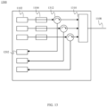
- FIG. 9 illustrates an optical fiber amplifier (OFA) 900 comprising an HECF 902 according to an embodiment.
- the HECF 902 has a core that is doped with rare earth ions such as erbium and connects two WDM couplers 904. Each of the WDM couplers receives the output of pump diodes 908.
- the optical power of the input 906 is amplified by the OFA and output on fibre 910.
- FIG. 10 illustrates a sensing system 1000 according to another embodiment.
- the HECF 1002 passes through sensing elements 1004.
- the signal source and data acquisition module are co-located in device 1006.
- sensing elements 1004 are fiber Bragg gratings (FBG).
- FBG fiber Bragg gratings
- FIG. 11 illustrates an optical transmitter 1100 with an integrated mode-division multiplexing module.
- the transmitter is typically contained in a housing to enable it to be easily integrated into optical transmission equipment.
- a transmitter 1100 may be packaged on its own or be integrated with a receiver to form a transceiver.
- a light source 1102 which may be a diode or laser, outputs at a continuous wavelength or mode.
- Data is applied to the light source 1102 by a modulator 1104 which is then multiplexed with other modulated light sources to be transmitted on the HECF 1108.
- the light source and modulator may be integrated together.
- FIG. 12 illustrates an optical receiver 1200 with an integrated mode-division de-multiplexing module.
- the receiver is typically contained in a housing to enable it to be easily integrated into optical transmission equipment.
- a receiver 1100 may be packaged on its own or be integrated with a transmitter 1100 to form a transceiver.
- Mode multiplexed data is received from the HECF 1108 and split into its modes in the mode demultiplexer 1206.
- Light of each mode is then received optical detectors 1202 which may be PIN diodes or APDs.
- FIG. 13 illustrates an optical transceiver 1300 with an integrated mode-division multiplexer/demultiplexer module.
- the transceiver is typically contained in a housing to enable it to be easily integrated into optical transmission equipment.
- the transceiver 1300 combines the functionality of a transmitter 1100 and a receiver 1200.
- a light source 1102 which may be a diode or laser, outputs at a continuous wavelength or mode.
- Data is applied to the light source 1102 by a modulator 1104 which is passed through a circulator 1312 and then multiplexed with other modulated light sources to be transmitted on the HECF 1108.
- the light source and modulator may be integrated together.
- Received light passes through the mode MUX/DeMUX 1310 and into the circulator 1312 that sends the demultiplexed received light to optical detectors 1202 which may be PIN diodes or APDs, to receive the data.
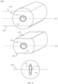
- the HECF 1400 may be fabricated using from a preform prepared using a modified chemical vapor deposition (MCVD) process.
- the preform has a cylindrical shape and includes a coaxial inner core 104 and outer cladding 102.
- the inner core 104 has a circular cross section.
- Opposing, longitudal sides 1402, 1404 are cut from the preform resulting in two opposing, flat, parallel sides 1406 1408.
- the cut preform is then heated so that the flat surfaces disappear due to the surface tension and the flow of material. Consequently, the circular core 104 becomes elliptical during the heating process.
- the cut preform with an elliptical core is pulled to form the optical fiber.
- the resulting optical fiber includes a core 104 having an elliptical cross section having an ellipticity between 2 and 40, and a cladding 102 having a circular cross section.
- the core 104 and the cladding 102 have a common central axis with the core 104 being enclosed by the cladding 102. Since the preform was fabricated through MCVD, it was able to include a trench 106 surrounding the core.
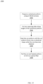
- FIG. 15 is a flowchart illustrating a method 1500 of manufacturing a HECF as shown in FIG. 14 .
- a cylindrical preform having an inner core 104 and an outer cladding 102 is formed.
- the inner core 104 has a circular cross section profile.
- the cylindrical preform may be formed using an MCVD process.
- two opposing sides 1402 1404 of the cylindrical preform are cut along a length of the cylindrical preform to produce a cut preform with opposing parallel surfaces 1406 1408 along a longitudinal axis of the cylindrical preform.
- the cutting of the preform is done in a manner that avoids cutting the inner core 104.
- the cut preform is heated.
- the surface tension of the exterior surface of the cut preform, subjected to the softening caused by the heating, allows the cut preform to distort until the exterior of the preform is circular again.
- the surface tension causes a distortion in the entire preform, so that when the cut preform assumes an outer circular profile, the inner core 104 has been distorted and result in an elliptical profile for the core 104.
- this generally elliptical core has an ellipticity of between 2 and 40.
- the outer cladding, after enclosing (or enveloping) the elliptical core has a generally circular cross section.
- the cut and heated preform is pulled to form an optical fiber.
- the core 104 and cladding 102 are generally co-axial, having a common central axis.
- An aspect of the disclosure includes an optical fiber including a core having an elliptical cross section and an ellipticity between 2 and 40.
- the optical fiber also includes a cladding, having a circular cross section, enclosing the core.
- An aspect of the disclosure includes the core and the cladding have a common central axis.
- An aspect of the disclosure includes an optical fiber wherein a difference of a refractive index of the cladding to a refractive index of the core is between 1 x 10 -2 and 1.5 x 10 -1 .
- An aspect of the disclosure includes an optical fiber wherein a ratio of a refractive index of the cladding to a refractive index of the core is between 1 x 10 -2 and 1.5 x 10 -1 .
- An aspect of the disclosure includes an optical fiber wherein a width of the core along a y-axis allows for single mode transmission.
- An aspect of the disclosure includes an optical fiber wherein a width of the core along an x-axis allows for the transmission of a plurality of mode pairs.
- An aspect of the disclosure includes an optical fiber wherein each of the plurality of mode pairs have two orthogonal linear polarizations.
- An aspect of the disclosure includes an optical fiber wherein the plurality of mode pairs have an effective index separation between the adjacent vector modes greater than 1 x 10 -4 .
- An aspect of the disclosure includes an optical fiber wherein the effective index separation is caused by thermal stress induced during the manufacture of the optical fiber and the elliptical shape of the core.
- An aspect of the disclosure includes an optical fiber wherein the core is doped with rare earth ions.
- An aspect of the disclosure includes an OFA wherein the core and the cladding have a common central axis.
- An aspect of the disclosure includes an OFA wherein a width of the core along a y-axis allows for single mode transmission and a width of the core along an x-axis allows for the transmission of a plurality of mode pairs.
- An aspect of the disclosure includes an optical transceiver including a transmit path and a receive path.
- the transmit path includes a plurality of light sources outputting a constant light signal at one of a plurality of vector modes.
- a plurality of optical modulators receives one of the constant light signals and outputs a modulated light signal.
- a plurality of circulators receives one of the modulated light signals and outputs one of the modulated light signals.
- a mode multiplexer receives each of the modulated light signals from the plurality of circulators to produce a mode multiplexed optical output.
- An optical fiber receives the mode multiplexed optical output.
- the optical fiber includes a core having an elliptical cross section and an ellipticity between 2 and 40.
- the optical fiber also includes a cladding having a circular cross section, with the core being enclosed by the cladding. In some embodiments. the core and the cladding have a common central axis.
- An aspect of the disclosure includes a trench portion situated between the core and the cladding.
- the trench portion is present in the optical fiber and isolates the core from the cladding.
- An aspect of the disclosure includes a cylindrical preform that is fabricated using a modified chemical vapor deposition (MCVD) process.
- MCVD modified chemical vapor deposition
- the elliptical profile is formed due to surface tension and the flow of material during the heating.
Landscapes
- Physics & Mathematics (AREA)
- Electromagnetism (AREA)
- Engineering & Computer Science (AREA)
- Optics & Photonics (AREA)
- Plasma & Fusion (AREA)
- Computer Networks & Wireless Communication (AREA)
- Signal Processing (AREA)
- General Physics & Mathematics (AREA)
- Lasers (AREA)
- Optical Fibers, Optical Fiber Cores, And Optical Fiber Bundles (AREA)
- Manufacture, Treatment Of Glass Fibers (AREA)
Description
- The present invention pertains to the field of fiber optic communications and in particular to an elliptical core optical fiber.
- The demand for Internet traffic and cloud computing places high demands on our current optical communications infrastructures. In particular, high bandwidth links are required for short-reach interconnects such as those found in data centers. Mode division multiplexing (MDM) over few-mode fibers (FMFs) is a promising approach to satisfy these data traffic demands. In MDM systems, the crosstalk between the spatial modes is one of the most critical impairments to signal quality.
- In present MDM systems, multiple-input multiple-output (MIMO) digital signal processing (DSP) are generally required to compensate for channel crosstalk and receive information data at the receiver side. A drawback of this full-MIMO approach is its complexity. Although the complexity can be reduced to some extent by minimizing differential modal group delay, it still requires heavy computational resource and power consumption.
- In order into reduce the DSP complexity, various design strategies in FMF have been proposed. One approach is to increase the effective index difference, δneff, between the spatial modes in order to reduce the complexity of the MIMO-DSP components.
- Although a partial MIMO-DSP approach may reduce the system complexity it is still desirable to have a MIMO-free design. To achieve this, some solutions propose polarization-maintaining (PM) FMF designs in which the polarization degeneracies of the spatial modes are reduced by using elliptical ring-core fiber (ERCF), PANDA ring-core fiber, or ERCF with an inner air hole. These fiber designs aim to enhance the effective index difference between adjacent vector modes. However, these solutions suffer from the drawback that the number of modes is limited.
- Therefore, there is a need for optical fiber, that is not subject to one or more limitations of the prior art.
- This background information is provided to reveal information believed by the applicant to be of possible relevance to the present invention. No admission is necessarily intended, nor should be construed, that any of the preceding information constitutes prior art against the present invention.
The document CORSI ALESSANDRO ET AL: "Design of Highly Elliptical Core Ten-Mode Fiber for Space Diversion Multiplexing with 2 X 2 MIMO", XP 011712656 shows the construction of an optical fiber with an elliptical core.
The documentUS 2014/071521 A1 also shows an optical fiber with an elliptical core.
The documentUS 2008/181567 A1 shows an optical fiber with a depressed index layer made of silica with holes. The document BO-HUN CHOI ET AL: "New pump wavelength of 1540-nm band for long-wavelength-band erbium-doped fiber amplifier (I-band EDFA)", XP 011101713 shows a regular erbium-doped fiber with a circular core.
The document WANG LI CHAN ET AL: "Linearly polarized vector modes: enabling MIMO free mode division multiplexing", XP 055931078 shows an optical fiber with an elliptical ring-core fiber. - The document CORSI ALESSANDRO: "Design of a Ten-Mode Polarization-Maintaining Few-Mode Fiber for MIMO-Less Data Transmission", 2018 EUROPEAN CONFERENCE ON OPTICAL COMMUNICATION (ECOC), IEEE, 23 September 2018, pages 1-3, XP033447607 discloses an optical fiber with an elliptical core with an ellipticity between 2-40.
- The present invention is defined by the independent claims. Further advantageous developments are shown by the dependent claims.
- An object of embodiments of the present invention is to provide an improved optical fiber for use in an MDM communications system.
- An aspect of the invention as defined by independent claim 1 includes an optical fiber including a core having an elliptical cross section and an ellipticity between 2 and 40. The optical fiber also includes a cladding having a circular cross section, with the cladding enclosing the core.
- An aspect of the disclosure includes the core and the cladding having a common central axis.
- An aspect of the disclosure includes an optical fiber wherein a difference of a refractive index of the cladding to a refractive index of the core is between 1 x 10² and 1.5 x 10⁻¹.
- An aspect of the disclosure includes an optical fiber wherein a ratio of a refractive index of the cladding to a refractive index of the core is between 1 x 10⁻² and 1.5 x 10⁻¹.
- An aspect of the disclosure includes an optical fiber comprises a trench located between the core and the cladding. The trench has a uniform width and encircles the core. The refractive index of the trench is lower than the refractive index of the cladding.
- An aspect of the disclosure includes an optical fiber wherein a width of the core along a y-axis allows for single mode transmission.
- An aspect of the invention as defined by independent claim 1 includes an optical fiber wherein a width of the core along an x-axis allows for the transmission of a plurality of mode pairs.
- An aspect of the invention as defined by independent claim 1 includes an optical fiber wherein each of the plurality of mode pairs have two orthogonal linear polarizations.
- An aspect of the invention as defined by independent claim 1 includes an optical fiber wherein the plurality of mode pairs have an effective index separation between the adjacent vector modes greater than 1 x 10⁻⁴.
- An aspect of the invention as defined by independent claim 1 includes an optical fiber wherein the effective index separation is caused by thermal stress induced during the manufacture of the optical fiber and the elliptical shape of the core.
- An aspect of the disclosure includes an optical fiber wherein the core is doped with rare earth ions.
- An aspect of the disclosure includes an optical fiber amplifier (OFA) including a first WDM coupler receiving an input signal and an output from a first pump optical source. An optical fiber receiving an output from the first WDM coupler. The optical fiber includes a core having an elliptical cross section having an ellipticity between 2 and 40. The optical fiber also includes a cladding, having a circular cross section, enclosing the core. The OFA also includes a second WDM coupler receiving the output of the optical fiber and an output of a second pump optical source. The second WDM coupler outputs an amplified optical signal.
- An aspect of the disclosure includes an OFA wherein the core and the cladding have a common central axis.
- An aspect of the disclosure includes an OFA wherein the core is doped with rare earth ions.
- An aspect of the disclosure includes an OFA wherein the optical fiber includes a trench located between the core and the cladding. The trench has a uniform width and encircles the core. The refractive index of the trench is lower than the refractive index of the cladding.
- An aspect of the disclosure includes an OFA wherein a width of the core along a y-axis allows for single mode transmission and a width of the core along an x-axis allows for the transmission of a plurality of mode pairs.
- An aspect of the disclosure includes a method for manufacturing an optical fiber as disclosed in independent claim 8. The method includes preparing a cylindrical preform having a cross section comprising an inner core and an outer cladding. The inner core has a circular profile. Cutting two opposing sides of the cylindrical preform along a length of the cylindrical preform to produce a cut preform with opposing parallel surfaces along a longitudinal axis of the cut preform. Heating the cut preform until the cut preform has a circular profile and an inner core of the cut preform has an elliptical profile. Pulling the cut preform to form the optical fiber having a core with an elliptical profile. The core has an ellipticity between 2 and 40, and a cladding has a circular cross section, with the core being enclosed by the cladding.
- An aspect of the disclosure includes the core and the cladding have a common central axis.
- An aspect of the disclosure includes a trench portion situated between the core and the cladding. The trench portion is present in the optical fiber and isolates the core from the cladding.
- An aspect of the disclosure includes a cylindrical preform that is fabricated using a modified chemical vapor deposition (MCVD) process.
- In another aspect of the disclosure the preform further includes a trench portion situated between the core and the cladding. The trench portion is present in the optical fiber and isolates the core from the cladding.
- In another aspect of the disclosure, the elliptical profile is formed due to surface tension and the flow of material during the heating.
- Embodiments have been described above in conjunctions with aspects of the present invention upon which they can be implemented. Those skilled in the art will appreciate that embodiments may be implemented in conjunction with the aspect with which they are described but may also be implemented with other embodiments of that aspect. When embodiments are mutually exclusive, or are otherwise incompatible with each other, it will be apparent to those skilled in the art. Some embodiments may be described in relation to one aspect, but may also be applicable to other aspects, as will be apparent to those of skill in the art.
- Further features and advantages of the present invention will become apparent from the following detailed description, taken in combination with the appended drawings, in which:
-
FIG. 1 illustrates a cross sectional view of an optical fiber according an embodiment. -
FIG. 2 illustrates a refractive index profile along the x-axis of an optical fiber according an embodiment. -
FIG. 3 illustrates a cross sectional view of an optical fiber and the compressive thermal stress that is induced into the core along the normal direction of the core/cladding border during the fiber drawing process. -
FIG. 4 illustrates a cross sectional view of an optical fiber according another embodiment. -
FIG. 5 illustrates a refractive index profile along the x-axis of an optical fiber according an embodiment. -
FIG. 6 illustrates a combined WDM and MDM optical communications system. -
FIG. 7 illustrates the mode multiplexing of data onto an optical fiber according to an embodiment. -
FIG. 8 illustrates the mode demultiplexing of data onto an optical fiber according to an embodiment. -
FIG. 9 illustrates an optical fiber amplifier utilizing an optical fiber according to an embodiment. -
FIG. 10 illustrates an optical fiber sensing apparatus utilizing an optical fiber according to an embodiment. -
FIG. 11 illustrates an MDM transmitter utilizing an optical fiber according to an embodiment. -
FIG. 12 illustrates an MDM receiver utilizing an optical fiber according to an embodiment. -
FIG. 13 illustrates an MDM transceiver utilizing an optical fiber according to an embodiment. -
FIG. 14 illustrates a method of manufacturing an HECF according to an embodiment. -
FIG. 15 is a flowchart of the method of manufacturing an HECF according to an embodiment. - It will be noted that throughout the appended drawings, like features are identified by like reference numerals.
- Embodiments of the invention comprise a polarization-maintaining highly elliptical core fiber (HECF). By combining the highly elliptical core shape and the thermal stress induced during the fiber fabrication, the birefringence values are elevated to be higher than 1x10⁻⁴, which reduces the mode coupling and in turn makes this fiber suitable for use in MIMO-free MDM transmission systems.
-
FIG. 1 illustrates a cross-section view of a highly elliptical core fiber (HECF) 100 according to a first embodiment of the invention. The optical fiber comprises acladding 102, which is typically the industry standard, 125 µm in diameter. At the center of the fiber is asolid core 104 surrounded by atrench 106. Though not shown inFIG. 1 , in most embodiments, the cladding is further surrounded by a buffer, which is in turn covered by a jacket as is known in the art. - The cross-section profile of the
core 104 is elliptical in shape. The core'scross section 104 has anx-axis 110 and a y-axis 108. In one embodiment thecore 104 has approximate cross-sectional dimensions of 38.5µm 202 along thex-axis 110 and 6.1 µm along the y-axis 108. The dimension along the short, y-axis 108, is selected to allow for single mode operations, n = 1 for TEm,n/TMm,n modes. The dimension of thex-axis 110 is selected to allow for multiple spatial modes to be distributed in a one-dimensional array in thex-axis 110. In other embodiments, the ellipticity, η, of the core, defined as the ratio of the cross-sectional length in the x-direction to the cross-sectional length in the y-direction, is between 2 and 40. Those skilled in the art will appreciate that thex-axis 110 may also be referred to as the major axis of the elliptical core, while the y-axis 108 may be referred to as the minor axis of the elliptical core. Rotation of the fiber so that the major axis is no longer horizontal should not be considered to be changing the alignment of the X and Y axes. Those skilled in the art will also appreciate that the ellipticity, η, may also be considered as the ratio of the width of the core along thex-axis 110 to the width of the core along the y-axis 108. - The
core 104 may be thought of as elliptic cylinder, such that the length of thex-axis 110 is greater than the length of the y-axis and therefore, thex-axis 110 forms the major axis of the ellipse and the y-axis 108 forms the minor axis of the ellipse. Thex-axis 110 and the y-axis 108 intersect at a right angle and the intersection of thex-axis 110 and the y-axis 108 defines the center of the elliptical cross-section. Thecore 104 has the shape of an elliptic cylinder with a central axis, also known as a longitudinal axis, running through the center of each elliptical cross-section of thecore 104. Thecladding 102 may be viewed as having a circular cross section with a center and has a cylindrical shape with a central axis running through the center of each circular cross-section of thecladding 102. Thecore 104 and thecladding 102 have a common central axis, such that thecore 104 is centered within thecladding 102. Accordingly, the HECF is formed so that thecladding 102 and thecore 104 share a common central axis. - Optical fiber is manufactured using a silica glass material comprised mainly of SiO2 and the
cladding 102 is comprised of a substantially pure silica glass material. Thecore 104 is manufactured by doping the SiO2 material with GeO2. In some embodiments, thecore 104 is comprised of SiO2 doped with 7.3 mol% of GeO2. - The
trench 106 surrounds thecore 104 and, in some embodiments is approximately 4.7µm wide 206. The trench is made of SiO2 doped with F, fluorine. In some embodiments the trench is doped with 2 mol% of F. The bending loss experienced by the HECF increases as the ellipticity increases, however the trench serves to reduce the bending loss of higher-order modes in the optical fiber. -
FIG. 2 shows the refractive index profile along thex-axis 110 for theoptical fiber 100. Thecore 104,trench 106, andcladding 102 have differing refractive indexes determined by their respective materials. In one embodiment the difference in refractive index between the core 104 andcladding 102,Δn 204, is approximately 1.1×10⁻². In embodiments, the refractive index difference between the core 104 and thecladding 102 is within the range 1×10⁻² ≤ Δn ≤ 1.5×10⁻¹. In one embodiment the difference in refractive index between thetrench 106 and thecladding 102, -Δn trench 208, is approximately 5.7×10⁻³. - The geometry of the highly elliptical core leads to geometry-enhanced birefringence in the optical fiber. This source of birefringence is related to the geometric structure of the core, where a higher core ellipticity will cause a higher value of birefringence.
- Referring to
FIG. 3 , during manufacture of the optical fibre, inconstant, compressivethermal stress 302 is induced into thecore 104, mainly along the y-axis 108 direction. During the fiber drawing and annealing process, the fiber becomes stressed due to different thermal expansion coefficients of thecore 104 and the cladding layers 102. Different amounts of stress are applied along long,x-axis 110 and short, y-axis 108 due to the asymmetry of its core structure. With the increase of this stress, the isotropic glass starts to become anisotropic, with a consequent change of the refractive indices along the principal, x and y stress directions. The thermal stress has the effect to increase the effective index difference (δneff ) between the two polarizations of the same spatial mode. - Optical fiber according to an embodiment of the invention may transmit data on five spatial mode groups with two-fold polarization degeneracy to obtain ten MDM channels. The supported modes are labeled as TE1n and TM1N, depending on the polarization state (respectively along the x-axis or the y-axis). In particular, the subscript "1" indicates the single mode operation along the short-axis (y-axis), while "n" is an integer indicating the number of the dark lines of the mode profile along the long-axis (x-axis).
- The elliptical shape of the core combined with thermal stress created during manufacturing produces a relatively large birefringence so that the modal effective index separation, δneff is greater than 1 x 10⁻⁴. This reduces the mode coupling inside the HECF so that the fiber modes can propagate without significant crosstalk up to a fiber length of approximately 1 km. This allows for transmission systems to be designed that do not require MIMO DSPs.
- In some embodiments the core may be doped with rare earth ions such as erbium and/or ytterbium in order to produce an optical active fiber.
-
FIG. 4 illustrates anoptical fiber 400 according to another embodiment with an alternative structure. In comparison to the embodiment depicted inFIG. 1 , this embodiment comprised acladding 102 andcore 104, but lacks atrench 106 between the core and cladding. Thetrench 106 helps to reduce the bending loss of higher-order modes in the fiber. However, in some embodiments, the bending loss may also be reduced by increasing therefractive index difference 204, Δn, to approximately 1.5×10⁻¹. -
FIG. 5 shows the refractive index profile along thex-axis 110 for theoptical fiber 400. Thecore 104 andcladding 102 have differing refractive indexes determined by their respective materials. In one embodiment the difference in refractive index between the core 104 andcladding 102,Δn 204, is approximately 1.1 x 10⁻². -
FIG. 6 illustrates a system incorporating embodiments of the invention. The invention can be used in the MIMO-free mode-division multiplexing system. The outputs fromWDM transmitters 602 are input toWDM couplers 604 and are multiplexed into a single output fiber. Each of the outputs from theWDM couplers 604 are then multiplexed by themode multiplexer 606 and converted into a corresponding mode in theHECF 608 and. After transmission through theHECF 608, the fiber modes are received and separated by themode demultiplexer 610 following by a number ofWDM couplers 612 to separate the wavelength channels and finally be detected by thereceivers 614. Due to the low crosstalk among the modes inside the fiber, a MIMO-DSP is not required. -
FIG. 7 illustrates an embodiment of a mode divisionmultiplexer utilizing HECF 702. Optical inputs of different modes TE11, TE12, ..., TE1n may be multiplexed onto theHECF 702 using fusedfiber mode couplers 704. -
FIG. 8 illustrates an embodiment of a mode divisiondemultiplexer utilizing HECF 802. Fusedfiber mode couplers 804 pass light of a predetermined mode to outputoptical fibers 806 in order to receive the signals from TE11, TE12, ..., TE1n. -
FIG. 9 illustrates an optical fiber amplifier (OFA) 900 comprising anHECF 902 according to an embodiment. TheHECF 902 has a core that is doped with rare earth ions such as erbium and connects twoWDM couplers 904. Each of the WDM couplers receives the output ofpump diodes 908. The optical power of theinput 906 is amplified by the OFA and output onfibre 910. -
FIG. 10 illustrates asensing system 1000 according to another embodiment. TheHECF 1002 passes throughsensing elements 1004. The signal source and data acquisition module are co-located indevice 1006. In some embodiments, sensingelements 1004 are fiber Bragg gratings (FBG). When light from theoptical signal source 1006 passes through thesensing elements 1004, light of a predetermined fiber mode is back reflected to the source and received by thedata acquisition module 1006. -
FIG. 11 illustrates anoptical transmitter 1100 with an integrated mode-division multiplexing module. The transmitter is typically contained in a housing to enable it to be easily integrated into optical transmission equipment. Atransmitter 1100 may be packaged on its own or be integrated with a receiver to form a transceiver. In some embodiments alight source 1102, which may be a diode or laser, outputs at a continuous wavelength or mode. Data is applied to thelight source 1102 by amodulator 1104 which is then multiplexed with other modulated light sources to be transmitted on theHECF 1108. In some embodiments, the light source and modulator may be integrated together. -
FIG. 12 illustrates anoptical receiver 1200 with an integrated mode-division de-multiplexing module. The receiver is typically contained in a housing to enable it to be easily integrated into optical transmission equipment. Areceiver 1100 may be packaged on its own or be integrated with atransmitter 1100 to form a transceiver. Mode multiplexed data is received from theHECF 1108 and split into its modes in themode demultiplexer 1206. Light of each mode is then receivedoptical detectors 1202 which may be PIN diodes or APDs. -
FIG. 13 illustrates anoptical transceiver 1300 with an integrated mode-division multiplexer/demultiplexer module. The transceiver is typically contained in a housing to enable it to be easily integrated into optical transmission equipment. Thetransceiver 1300 combines the functionality of atransmitter 1100 and areceiver 1200. In some embodiments alight source 1102, which may be a diode or laser, outputs at a continuous wavelength or mode. Data is applied to thelight source 1102 by amodulator 1104 which is passed through acirculator 1312 and then multiplexed with other modulated light sources to be transmitted on theHECF 1108. In some embodiments, the light source and modulator may be integrated together. Received light passes through the mode MUX/DeMUX 1310 and into thecirculator 1312 that sends the demultiplexed received light tooptical detectors 1202 which may be PIN diodes or APDs, to receive the data. - As shown in
FIG. 14 , theHECF 1400 may be fabricated using from a preform prepared using a modified chemical vapor deposition (MCVD) process. The preform has a cylindrical shape and includes a coaxialinner core 104 andouter cladding 102. Theinner core 104 has a circular cross section. Opposing,longitudal sides parallel sides 1406 1408. The cut preform is then heated so that the flat surfaces disappear due to the surface tension and the flow of material. Consequently, thecircular core 104 becomes elliptical during the heating process. The cut preform with an elliptical core is pulled to form the optical fiber. The resulting optical fiber includes acore 104 having an elliptical cross section having an ellipticity between 2 and 40, and acladding 102 having a circular cross section. Thecore 104 and thecladding 102 have a common central axis with thecore 104 being enclosed by thecladding 102. Since the preform was fabricated through MCVD, it was able to include atrench 106 surrounding the core. - Those skilled in the art will appreciate that it may be possible to make a plurality of cuts that are not necessarily aligned with each other (e.g. without creating longitudinal sides) but that taken as a whole, after the heating induced reshaping, result in the elliptical core discussed above.
-
FIG. 15 is a flowchart illustrating amethod 1500 of manufacturing a HECF as shown inFIG. 14 . Instep 1502, a cylindrical preform having aninner core 104 and anouter cladding 102 is formed. Theinner core 104 has a circular cross section profile. The cylindrical preform may be formed using an MCVD process. Instep 1504, two opposingsides 1402 1404 of the cylindrical preform are cut along a length of the cylindrical preform to produce a cut preform with opposingparallel surfaces 1406 1408 along a longitudinal axis of the cylindrical preform. In various embodiments, the cutting of the preform is done in a manner that avoids cutting theinner core 104. Instep 1506, the cut preform is heated. The surface tension of the exterior surface of the cut preform, subjected to the softening caused by the heating, allows the cut preform to distort until the exterior of the preform is circular again. The surface tension causes a distortion in the entire preform, so that when the cut preform assumes an outer circular profile, theinner core 104 has been distorted and result in an elliptical profile for thecore 104. As discussed above, this generally elliptical core has an ellipticity of between 2 and 40. The outer cladding, after enclosing (or enveloping) the elliptical core has a generally circular cross section. Instep 1508, the cut and heated preform is pulled to form an optical fiber. In some embodiments, thecore 104 andcladding 102 are generally co-axial, having a common central axis. - An aspect of the disclosure includes an optical fiber including a core having an elliptical cross section and an ellipticity between 2 and 40. The optical fiber also includes a cladding, having a circular cross section, enclosing the core.
- An aspect of the disclosure includes the core and the cladding have a common central axis.
- An aspect of the disclosure includes an optical fiber wherein a difference of a refractive index of the cladding to a refractive index of the core is between 1 x 10⁻² and 1.5 x 10⁻¹.
- An aspect of the disclosure includes an optical fiber wherein a ratio of a refractive index of the cladding to a refractive index of the core is between 1 x 10⁻² and 1.5 x 10⁻¹.
- An aspect of the disclosure includes an optical fiber comprising a trench located between the core and the cladding. The trench has a uniform width and encircles the core. The refractive index of the trench is lower than the refractive index of the cladding.
- An aspect of the disclosure includes an optical fiber wherein a width of the core along a y-axis allows for single mode transmission.
- An aspect of the disclosure includes an optical fiber wherein a width of the core along an x-axis allows for the transmission of a plurality of mode pairs.
- An aspect of the disclosure includes an optical fiber wherein each of the plurality of mode pairs have two orthogonal linear polarizations.
- An aspect of the disclosure includes an optical fiber wherein the plurality of mode pairs have an effective index separation between the adjacent vector modes greater than 1 x 10⁻⁴.
- An aspect of the disclosure includes an optical fiber wherein the effective index separation is caused by thermal stress induced during the manufacture of the optical fiber and the elliptical shape of the core.
- An aspect of the disclosure includes an optical fiber wherein the core is doped with rare earth ions.
- An aspect of the disclosure includes an optical fiber amplifier (OFA) including a first WDM coupler receiving an input signal and an output from a first pump optical source. An optical fiber receiving an output from the first WDM coupler. The optical fiber includes a core having an elliptical cross section having an ellipticity between 2 and 40. The optical fiber also includes a cladding, having a circular cross section, enclosing the core. The OFA also includes a second WDM coupler receiving the output of the optical fiber and an output of a second pump optical source. The second WDM coupler outputs an amplified optical signal.
- An aspect of the disclosure includes an OFA wherein the core and the cladding have a common central axis.
- An aspect of the disclosure includes an OFA wherein the core is doped with rare earth ions.
- An aspect of the disclosure includes an OFA wherein the optical fiber includes a trench located between the core and the cladding. The trench has a uniform width and encircles the core. The refractive index of the trench is lower than the refractive index of the cladding.
- An aspect of the disclosure includes an OFA wherein a width of the core along a y-axis allows for single mode transmission and a width of the core along an x-axis allows for the transmission of a plurality of mode pairs.
- An aspect of the disclosure includes an optical sensor detecting an optical transmission of an optical mode. The optical sensor includes a plurality of sensing elements disposed along an optical fiber. The optical fiber includes a core having an elliptical cross section and an ellipticity between 2 and 40. The optical fiber includes a cladding having a circular cross section. The core is enclosed by the cladding. The optical fiber receives an input signal including a plurality of vector modes. Each of the plurality of sensing elements reflects one of the plurality of vector modes. A data acquisition module receives one of the plurality of the vector modes reflected by one of the plurality of sensing elements. In some embodiments, the core and the cladding have a common central axis.
- An aspect of the disclosure includes an optical transmitter module. The module includes a plurality of light sources. Each of the plurality of light sources outputs a constant light signal at one of a plurality of vector modes. A plurality of optical modulators receive one of the constant light signals and output a modulated light signal. A mode multiplexer receives each of the modulated light signals to produce a mode multiplexed optical output. An optical fiber receives the mode multiplexed optical output. The optical fiber includes a core having an elliptical cross section having an ellipticity between 2 and 40. The optical fiber also includes a cladding having a circular cross section, with the core being enclosed by the cladding. In some embodiments. the core and the cladding have a common central axis.
- An aspect of the disclosure includes an optical receiver module including an optical fiber. The optical fiber receives a mode multiplexed optical signal. The optical fiber includes a core having an elliptical cross section having an ellipticity between 2 and 40. The optical fiber also includes a cladding. The core is enclosed by the cladding. The optical receiver module also includes a mode demultiplexer receiving the mode multiplexed optical signal from the optical fiber and outputting a plurality of modulated light signals. Each of the plurality of modulated light signals includes light at one of a plurality of vector modes. A plurality of optical detectors each receive one of the plurality of modulated light signals. In some embodiments. the core and the cladding have a common central axis.
- An aspect of the disclosure includes an optical transceiver including a transmit path and a receive path. The transmit path includes a plurality of light sources outputting a constant light signal at one of a plurality of vector modes. A plurality of optical modulators receives one of the constant light signals and outputs a modulated light signal. A plurality of circulators receives one of the modulated light signals and outputs one of the modulated light signals. A mode multiplexer receives each of the modulated light signals from the plurality of circulators to produce a mode multiplexed optical output. An optical fiber receives the mode multiplexed optical output. The optical fiber includes a core having an elliptical cross section and an ellipticity between 2 and 40. The optical fiber also includes a cladding having a circular cross section, with the core being enclosed by the cladding. In some embodiments. the core and the cladding have a common central axis.
- The receive path includes a mode demultiplexer receiving the mode multiplexed optical signal from the optical fiber and outputting a plurality of received modulated light signals. Each of the plurality of received modulated light signals includes light at one of the plurality of vector modes. A plurality of optical detectors each receives one of the plurality of received modulated light signals via the plurality of circulators.
- An aspect of the disclosure includes a method for manufacturing an optical fiber. The method includes preparing a cylindrical preform having a cross section comprising an inner core and an outer cladding. The inner core has a circular profile. Cutting two opposing sides of the cylindrical preform along a length of the cylindrical preform to produce a cut preform with opposing parallel surfaces along a longitudinal axis of the cut preform. Heating the cut preform until the cut preform has a circular profile and an inner core of the cut preform has an elliptical profile. Pulling the cut preform to form the optical fiber having a core with an elliptical profile. The core has an ellipticity between 2 and 40, and a cladding has a circular cross section. The core being enclosed by the cladding. In some embodiments. the core and the cladding have a common central axis.
- An aspect of the disclosure includes a trench portion situated between the core and the cladding. The trench portion is present in the optical fiber and isolates the core from the cladding.
- An aspect of the disclosure includes a cylindrical preform that is fabricated using a modified chemical vapor deposition (MCVD) process.
- In another aspect of the disclosure the preform further includes a trench portion situated between the core and the cladding. The trench portion is present in the optical fiber and isolates the core from the cladding.
- In another aspect of the disclosure, the elliptical profile is formed due to surface tension and the flow of material during the heating.
- Unless defined otherwise, all technical and scientific terms used herein have the same meaning as commonly understood by one of ordinary skill in the art to which this invention belongs.
- Although the present invention has been described with reference to specific features and embodiments thereof, it is evident that various modifications and combinations can be made thereto without departing from the invention which is defined in claim 1. The specification and drawings are, accordingly, to be regarded simply as an illustration of the invention as defined by the appended claims.
Claims (11)
- An optical fiber (100) comprising:a core (104) having an elliptical cross section, the core (104) having an ellipticity between 2 and 40,wherein ellipticity is defined as a ratio of a cross-sectional length along an x-axis (110) to a cross-sectional length along an y-axis (108),wherein the x-axis (110) forms a major axis of the ellipse of the elliptical cross section and the y-axis (108) forms the minor axis of the ellipse of the elliptical cross section, anda cladding (102), having a circular cross section, enclosing the core (104),wherein a width of the core (104) along the x-axis (110) allows for the transmission of a plurality of mode pairs, wherein each of the plurality of mode pairs is comprised of two orthogonal linear polarizations,wherein the plurality of mode pairs have an effective index separation between adjacent vector modes greater than 1 x 10⁻⁴,wherein the optical fiber is a polarization maintaining fiber;and the optical fiber being characterized in that: the effective index separation is caused by thermal stress induced during the manufacture of the optical fiber and the elliptical shape of the core (104).
- The optical fiber (100) of claim 1 wherein the core (104) and the cladding (102) have a common central axis.
- The optical fiber (100) of any of claims 1 or 2 wherein a difference of a refractive index of the cladding (102) to a refractive index of the core (104) is between 1 x 10⁻² and 1.5 x 10⁻¹.
- The optical fiber (100) of any of claims 1, 2, or 3 further comprising a trench (106) located between the core (104) and the cladding (102), the trench (104) having a uniform width and encircling the core (104), a refractive index of the trench (106) being lower than the refractive index of the cladding (102).
- The optical fiber (10) of any of claims 1, 2, 3, or 4 wherein a width of the core (104) along the y-axis (108) allows for single mode transmission.
- The optical fiber (100) of any of claims 1 to 5 wherein the core (104) is doped with rare earth ions.
- An optical fiber amplifier (900) comprising:a first WDM coupler (904) receiving an input signal and an output from a first pump optical source;an optical fiber (902) according to claim 6, and receiving an output from the first WDM coupler (904); anda second WDM coupler (904) receiving the output of the optical fiber (902) and an output of a second pump optical source (908), the second WDM coupler outputting an amplified optical signal.
- A method for manufacturing an optical fiber, the method comprising:preparing (1502) a cylindrical preform having a cross section comprising an inner core and an outer cladding, the inner core having a circular profile;cutting (1504) two opposing sides of the cylindrical preform along a length of the cylindrical preform to produce a cut preform with opposing parallel surfaces along a longitudinal axis of the cut preform,heating (1506) the cut preform until cut preform has a circular profile and an inner core of the cut preform having an elliptical profile;pulling (1508) the cut preform to form the optical fiber, the optical fiber comprising a core having an elliptical profile, the core having an ellipticity between 2 and 40, and a cladding having a circular cross section, ,wherein ellipticity is defined as a ratio of a cross-sectional length along an x-axis to a cross-sectional length along an y-axis,wherein the x-axis forms a major axis of the ellipse of the elliptical cross section and the y-axis form the minor axis of the ellipse of the elliptical cross section,wherein the core is enclosed by the cladding,wherein a width of the core along the x-axis allows for the transmission of a plurality of mode pairs,wherein each of the plurality of mode pairs is comprised of two orthogonal linear polarizations,wherein the plurality of mode pairs have an effective index separation between adjacent vector modes greater than 1 x 10⁻⁴, andwherein the optical fiber is a polarization maintaining fiber; andthe optical fiber being characterized in that : the effective index separation is caused by thermal stress induced during the manufacture of the optical fiber and the elliptical shape of the core.
- The method of claim 8, wherein the cylindrical preform further comprises a trench portion situated between the core and the cladding, the trench portion being present in the optical fiber and isolating the core from the cladding.
- The method of any of claims 8 or 9, wherein the cylindrical preform is fabricated using a modified chemical vapor deposition (MCVD) process.
- The method of any of claims 8 to 10, wherein the elliptical profile is formed due to a surface tension and a flow of material during the heating.
Applications Claiming Priority (3)
| Application Number | Priority Date | Filing Date | Title |
|---|---|---|---|
| US201962880928P | 2019-07-31 | 2019-07-31 | |
| US16/943,713 US11916348B2 (en) | 2019-07-31 | 2020-07-30 | Polarization-maintaining highly elliptical core fiber with stress-induced birefringence |
| PCT/CA2020/051054 WO2021016719A1 (en) | 2019-07-31 | 2020-07-31 | Polarization-maintaining highly elliptical core fiber with stress-induced birefringence |
Publications (3)
| Publication Number | Publication Date |
|---|---|
| EP3977185A1 EP3977185A1 (en) | 2022-04-06 |
| EP3977185A4 EP3977185A4 (en) | 2022-07-27 |
| EP3977185B1 true EP3977185B1 (en) | 2025-05-21 |
Family
ID=74229040
Family Applications (1)
| Application Number | Title | Priority Date | Filing Date |
|---|---|---|---|
| EP20847919.6A Active EP3977185B1 (en) | 2019-07-31 | 2020-07-31 | Polarization-maintaining highly elliptical core fiber with stress-induced birefringence |
Country Status (5)
| Country | Link |
|---|---|
| US (1) | US11916348B2 (en) |
| EP (1) | EP3977185B1 (en) |
| JP (1) | JP2022542439A (en) |
| CN (1) | CN114072711B (en) |
| WO (1) | WO2021016719A1 (en) |
Families Citing this family (4)
| Publication number | Priority date | Publication date | Assignee | Title |
|---|---|---|---|---|
| CN113433610A (en) * | 2021-06-10 | 2021-09-24 | 艾菲博(宁波)光电科技有限责任公司 | Hollow polarization maintaining optical fiber |
| CN113466993B (en) * | 2021-07-07 | 2022-12-02 | 天津大学 | Polarization-maintaining mode group selection type photon lantern and manufacturing and application thereof |
| US12126134B2 (en) * | 2021-08-06 | 2024-10-22 | Huawei Technologies Canada Co., Ltd. | Systems and methods to increase pump conversion efficiency of an optical fiber |
| CN113740958B (en) * | 2021-08-27 | 2023-09-08 | 烽火通信科技股份有限公司 | Few-mode optical fiber with high mode number and weak coupling |
Family Cites Families (19)
| Publication number | Priority date | Publication date | Assignee | Title |
|---|---|---|---|---|
| JPS5835503A (en) * | 1981-08-27 | 1983-03-02 | Nippon Telegr & Teleph Corp <Ntt> | Single lineary polarizing optical fiber of zero polarization scattering |
| JPH06235838A (en) * | 1993-02-12 | 1994-08-23 | Sumitomo Electric Ind Ltd | Manufacturing method of polarization-maintaining optical fiber |
| US6538807B2 (en) * | 2000-09-07 | 2003-03-25 | Sumitomo Electric Industries, Ltd. | Amplification optical fiber, fiber optic amplifier, optical transmitter, and optical communication system |
| US6563995B2 (en) * | 2001-04-02 | 2003-05-13 | Lightwave Electronics | Optical wavelength filtering apparatus with depressed-index claddings |
| WO2005082801A2 (en) * | 2004-02-20 | 2005-09-09 | Corning Incorporated | Optical fiber and method for making such fiber |
| US7203407B2 (en) * | 2004-10-21 | 2007-04-10 | Corning Incorporated | Rare earth doped single polarization double clad optical fiber and a method for making such fiber |
| US20060171426A1 (en) * | 2005-02-02 | 2006-08-03 | Andrei Starodoumov | Fiber-laser with intracavity polarization maintaining coupler providing plane polarized output |
| US7382957B2 (en) * | 2006-01-30 | 2008-06-03 | Corning Incorporated | Rare earth doped double clad optical fiber with plurality of air holes and stress rods |
| US7526166B2 (en) | 2007-01-31 | 2009-04-28 | Corning Incorporated | High numerical aperture fiber |
| JP2010177469A (en) * | 2009-01-29 | 2010-08-12 | Furukawa Electric Co Ltd:The | Optical fiber laser and optical fiber amplifier |
| CN102859814A (en) * | 2010-03-19 | 2013-01-02 | 株式会社藤仓 | Optical Fiber Amplifier, And Fiber Laser Device Using Same |
| US8837038B2 (en) | 2012-09-13 | 2014-09-16 | Polaronyx, Inc. | Fiber geometrical management for TEM00 mode pulse energy scaling of fiber lasers and amplifiers |
| US8977095B2 (en) * | 2012-09-24 | 2015-03-10 | Corning Incorporated | Polarization maintaining optical fibers with intracore stress mechanisms |
| US9031099B2 (en) * | 2013-04-19 | 2015-05-12 | Ipg Photonics Corporation | Fiber with asymmetrical core and method for manufacturing same |
| CN105985015B (en) * | 2015-02-28 | 2018-10-23 | 武汉长盈通光电技术有限公司 | A kind of ellipse core polarization maintaining optical fibre and its manufacturing method |
| US9917410B2 (en) * | 2015-12-04 | 2018-03-13 | Nlight, Inc. | Optical mode filter employing radially asymmetric fiber |
| CN109937372B (en) * | 2016-11-04 | 2020-12-29 | 德拉克通信法国集团公司 | Coupled few-mode fibers and corresponding optical links and optical systems |
| CN106886071B (en) * | 2017-03-23 | 2019-05-21 | 华中科技大学 | A degenerate multimode fiber with completely separated eigenmodes |
| CN107300738B (en) * | 2017-06-27 | 2024-05-24 | 中国电子科技集团公司电子科学研究院 | Optical fiber |
-
2020
- 2020-07-30 US US16/943,713 patent/US11916348B2/en active Active
- 2020-07-31 CN CN202080049431.0A patent/CN114072711B/en active Active
- 2020-07-31 EP EP20847919.6A patent/EP3977185B1/en active Active
- 2020-07-31 JP JP2022506412A patent/JP2022542439A/en active Pending
- 2020-07-31 WO PCT/CA2020/051054 patent/WO2021016719A1/en not_active Ceased
Non-Patent Citations (2)
| Title |
|---|
| CORSI ALESSANDRO ET AL: "Design of a Ten-Mode Polarization-Maintaining Few-Mode Fiber for MIMO-Less Data Transmission", 2018 EUROPEAN CONFERENCE ON OPTICAL COMMUNICATION (ECOC), IEEE, 23 September 2018 (2018-09-23), pages 1 - 3, XP033447607, DOI: 10.1109/ECOC.2018.8535326 * |
| RUSCH LESLIE A ET AL: "Fiber transmission demonstrations in vector mode space division multiplexing", FRONTIERS OF OPTOELECTRONICS, HIGHER EDUCATION PRESS, HEIDELBERG, vol. 11, no. 2, 4 June 2018 (2018-06-04), pages 155 - 162, XP036545195, ISSN: 2095-2759, [retrieved on 20180604], DOI: 10.1007/S12200-018-0812-2 * |
Also Published As
| Publication number | Publication date |
|---|---|
| JP2022542439A (en) | 2022-10-03 |
| US11916348B2 (en) | 2024-02-27 |
| CN114072711A (en) | 2022-02-18 |
| WO2021016719A1 (en) | 2021-02-04 |
| EP3977185A4 (en) | 2022-07-27 |
| US20210036480A1 (en) | 2021-02-04 |
| EP3977185A1 (en) | 2022-04-06 |
| CN114072711B (en) | 2024-12-27 |
Similar Documents
| Publication | Publication Date | Title |
|---|---|---|
| US11916348B2 (en) | Polarization-maintaining highly elliptical core fiber with stress-induced birefringence | |
| US10784961B2 (en) | Concentric fiber for space-division multiplexed optical communications and method of use | |
| JP5170909B2 (en) | Optical transmission system and multi-core optical fiber | |
| EP2369376B1 (en) | Multi-core optical fiber | |
| Cui et al. | Five-LP-mode IM/DD MDM transmission based on degenerate-mode-selective couplers with side-polishing processing | |
| EP2365654B1 (en) | Multicore fiber transmission systems and methods | |
| CN104067152B (en) | Few mode optical fibers for mode division multiplexing | |
| WO2013035347A1 (en) | Multicore optical fiber and optical transmission method | |
| US10830946B2 (en) | Coupled few mode fibers, and corresponding optical link and optical system | |
| US10277354B1 (en) | Efficient mode coupling using ladder fibers | |
| JP5137492B2 (en) | Optical transmission line and optical transmission system | |
| Takenaga et al. | Multicore fibre-based mode multiplexer/demultiplexer for three-mode operation of LP 01, LP 11a, and LP 11b | |
| JP2013097241A (en) | Multi-core interface | |
| Corral et al. | Mode-selective couplers for two-mode transmission at 850 nm in standard SMF | |
| CN113466993B (en) | Polarization-maintaining mode group selection type photon lantern and manufacturing and application thereof | |
| JP2010118856A (en) | Optical wavelength division multiplex communication system, exciter, and mode filter | |
| US10454607B2 (en) | Mode division multiplexing systems and methods using a rectangular-core optical fiber | |
| JP6258618B2 (en) | Multi-core optical fiber | |
| CN109073825A (en) | Less fundamental mode optical fibre used in mode division multiplexing | |
| Corsi et al. | Design of a ten-mode polarization-maintaining few-mode fiber for MIMO-less data transmission | |
| JPWO2013035347A1 (en) | Optical transmission method | |
| US20060239610A1 (en) | Apparatus for propagating optical radiation | |
| CN106199826A (en) | Polarization maintaining optical fibre | |
| WO2020257660A1 (en) | Multifiber connector for concentric multi-core fiber | |
| Tsang et al. | Silicon photonics for spatially multiplexed high capacity optical fiber communications |
Legal Events
| Date | Code | Title | Description |
|---|---|---|---|
| STAA | Information on the status of an ep patent application or granted ep patent |
Free format text: STATUS: THE INTERNATIONAL PUBLICATION HAS BEEN MADE |
|
| PUAI | Public reference made under article 153(3) epc to a published international application that has entered the european phase |
Free format text: ORIGINAL CODE: 0009012 |
|
| STAA | Information on the status of an ep patent application or granted ep patent |
Free format text: STATUS: REQUEST FOR EXAMINATION WAS MADE |
|
| 17P | Request for examination filed |
Effective date: 20211229 |
|
| AK | Designated contracting states |
Kind code of ref document: A1 Designated state(s): AL AT BE BG CH CY CZ DE DK EE ES FI FR GB GR HR HU IE IS IT LI LT LU LV MC MK MT NL NO PL PT RO RS SE SI SK SM TR |
|
| A4 | Supplementary search report drawn up and despatched |
Effective date: 20220629 |
|
| RIC1 | Information provided on ipc code assigned before grant |
Ipc: H04J 14/04 20060101ALI20220623BHEP Ipc: H01S 3/0941 20060101ALI20220623BHEP Ipc: G02B 6/024 20060101ALI20220623BHEP Ipc: G02B 6/036 20060101ALI20220623BHEP Ipc: H01S 3/16 20060101ALI20220623BHEP Ipc: H01S 3/094 20060101ALI20220623BHEP Ipc: H01S 3/067 20060101ALI20220623BHEP Ipc: H04J 14/02 20060101ALI20220623BHEP Ipc: G02B 6/02 20060101AFI20220623BHEP |
|
| DAV | Request for validation of the european patent (deleted) | ||
| DAX | Request for extension of the european patent (deleted) | ||
| GRAP | Despatch of communication of intention to grant a patent |
Free format text: ORIGINAL CODE: EPIDOSNIGR1 |
|
| STAA | Information on the status of an ep patent application or granted ep patent |
Free format text: STATUS: GRANT OF PATENT IS INTENDED |
|
| INTG | Intention to grant announced |
Effective date: 20250103 |
|
| RIN1 | Information on inventor provided before grant (corrected) |
Inventor name: CHANG, JUNHO Inventor name: LA ROCHELLE, SOPHIE Inventor name: CORSI, ALESSANDRO |
|
| GRAS | Grant fee paid |
Free format text: ORIGINAL CODE: EPIDOSNIGR3 |
|
| GRAA | (expected) grant |
Free format text: ORIGINAL CODE: 0009210 |
|
| STAA | Information on the status of an ep patent application or granted ep patent |
Free format text: STATUS: THE PATENT HAS BEEN GRANTED |
|
| AK | Designated contracting states |
Kind code of ref document: B1 Designated state(s): AL AT BE BG CH CY CZ DE DK EE ES FI FR GB GR HR HU IE IS IT LI LT LU LV MC MK MT NL NO PL PT RO RS SE SI SK SM TR |
|
| REG | Reference to a national code |
Ref country code: GB Ref legal event code: FG4D |
|
| REG | Reference to a national code |
Ref country code: CH Ref legal event code: EP |
|
| REG | Reference to a national code |
Ref country code: DE Ref legal event code: R096 Ref document number: 602020051775 Country of ref document: DE |
|
| REG | Reference to a national code |
Ref country code: IE Ref legal event code: FG4D |
|
| REG | Reference to a national code |
Ref country code: NL Ref legal event code: MP Effective date: 20250521 |
|
| PG25 | Lapsed in a contracting state [announced via postgrant information from national office to epo] |
Ref country code: FI Free format text: LAPSE BECAUSE OF FAILURE TO SUBMIT A TRANSLATION OF THE DESCRIPTION OR TO PAY THE FEE WITHIN THE PRESCRIBED TIME-LIMIT Effective date: 20250521 Ref country code: PT Free format text: LAPSE BECAUSE OF FAILURE TO SUBMIT A TRANSLATION OF THE DESCRIPTION OR TO PAY THE FEE WITHIN THE PRESCRIBED TIME-LIMIT Effective date: 20250922 Ref country code: ES Free format text: LAPSE BECAUSE OF FAILURE TO SUBMIT A TRANSLATION OF THE DESCRIPTION OR TO PAY THE FEE WITHIN THE PRESCRIBED TIME-LIMIT Effective date: 20250521 |
|
| PGFP | Annual fee paid to national office [announced via postgrant information from national office to epo] |
Ref country code: DE Payment date: 20250604 Year of fee payment: 6 |
|
| REG | Reference to a national code |
Ref country code: LT Ref legal event code: MG9D |
|
| PG25 | Lapsed in a contracting state [announced via postgrant information from national office to epo] |
Ref country code: GR Free format text: LAPSE BECAUSE OF FAILURE TO SUBMIT A TRANSLATION OF THE DESCRIPTION OR TO PAY THE FEE WITHIN THE PRESCRIBED TIME-LIMIT Effective date: 20250822 Ref country code: NO Free format text: LAPSE BECAUSE OF FAILURE TO SUBMIT A TRANSLATION OF THE DESCRIPTION OR TO PAY THE FEE WITHIN THE PRESCRIBED TIME-LIMIT Effective date: 20250821 |
|
| PG25 | Lapsed in a contracting state [announced via postgrant information from national office to epo] |
Ref country code: NL Free format text: LAPSE BECAUSE OF FAILURE TO SUBMIT A TRANSLATION OF THE DESCRIPTION OR TO PAY THE FEE WITHIN THE PRESCRIBED TIME-LIMIT Effective date: 20250521 Ref country code: PL Free format text: LAPSE BECAUSE OF FAILURE TO SUBMIT A TRANSLATION OF THE DESCRIPTION OR TO PAY THE FEE WITHIN THE PRESCRIBED TIME-LIMIT Effective date: 20250521 |
|
| PG25 | Lapsed in a contracting state [announced via postgrant information from national office to epo] |
Ref country code: BG Free format text: LAPSE BECAUSE OF FAILURE TO SUBMIT A TRANSLATION OF THE DESCRIPTION OR TO PAY THE FEE WITHIN THE PRESCRIBED TIME-LIMIT Effective date: 20250521 |
|
| PG25 | Lapsed in a contracting state [announced via postgrant information from national office to epo] |
Ref country code: HR Free format text: LAPSE BECAUSE OF FAILURE TO SUBMIT A TRANSLATION OF THE DESCRIPTION OR TO PAY THE FEE WITHIN THE PRESCRIBED TIME-LIMIT Effective date: 20250521 |
|
| PG25 | Lapsed in a contracting state [announced via postgrant information from national office to epo] |
Ref country code: RS Free format text: LAPSE BECAUSE OF FAILURE TO SUBMIT A TRANSLATION OF THE DESCRIPTION OR TO PAY THE FEE WITHIN THE PRESCRIBED TIME-LIMIT Effective date: 20250821 |
|
| PG25 | Lapsed in a contracting state [announced via postgrant information from national office to epo] |
Ref country code: IS Free format text: LAPSE BECAUSE OF FAILURE TO SUBMIT A TRANSLATION OF THE DESCRIPTION OR TO PAY THE FEE WITHIN THE PRESCRIBED TIME-LIMIT Effective date: 20250921 |
|
| PG25 | Lapsed in a contracting state [announced via postgrant information from national office to epo] |
Ref country code: LV Free format text: LAPSE BECAUSE OF FAILURE TO SUBMIT A TRANSLATION OF THE DESCRIPTION OR TO PAY THE FEE WITHIN THE PRESCRIBED TIME-LIMIT Effective date: 20250521 |
|
| REG | Reference to a national code |
Ref country code: AT Ref legal event code: MK05 Ref document number: 1797210 Country of ref document: AT Kind code of ref document: T Effective date: 20250521 |
|
| PG25 | Lapsed in a contracting state [announced via postgrant information from national office to epo] |
Ref country code: SM Free format text: LAPSE BECAUSE OF FAILURE TO SUBMIT A TRANSLATION OF THE DESCRIPTION OR TO PAY THE FEE WITHIN THE PRESCRIBED TIME-LIMIT Effective date: 20250521 Ref country code: DK Free format text: LAPSE BECAUSE OF FAILURE TO SUBMIT A TRANSLATION OF THE DESCRIPTION OR TO PAY THE FEE WITHIN THE PRESCRIBED TIME-LIMIT Effective date: 20250521 Ref country code: AT Free format text: LAPSE BECAUSE OF FAILURE TO SUBMIT A TRANSLATION OF THE DESCRIPTION OR TO PAY THE FEE WITHIN THE PRESCRIBED TIME-LIMIT Effective date: 20250521 |
|
| PG25 | Lapsed in a contracting state [announced via postgrant information from national office to epo] |
Ref country code: CZ Free format text: LAPSE BECAUSE OF FAILURE TO SUBMIT A TRANSLATION OF THE DESCRIPTION OR TO PAY THE FEE WITHIN THE PRESCRIBED TIME-LIMIT Effective date: 20250521 |
|
| PG25 | Lapsed in a contracting state [announced via postgrant information from national office to epo] |
Ref country code: EE Free format text: LAPSE BECAUSE OF FAILURE TO SUBMIT A TRANSLATION OF THE DESCRIPTION OR TO PAY THE FEE WITHIN THE PRESCRIBED TIME-LIMIT Effective date: 20250521 |
|
| PG25 | Lapsed in a contracting state [announced via postgrant information from national office to epo] |
Ref country code: SK Free format text: LAPSE BECAUSE OF FAILURE TO SUBMIT A TRANSLATION OF THE DESCRIPTION OR TO PAY THE FEE WITHIN THE PRESCRIBED TIME-LIMIT Effective date: 20250521 Ref country code: RO Free format text: LAPSE BECAUSE OF FAILURE TO SUBMIT A TRANSLATION OF THE DESCRIPTION OR TO PAY THE FEE WITHIN THE PRESCRIBED TIME-LIMIT Effective date: 20250521 |
|
| PG25 | Lapsed in a contracting state [announced via postgrant information from national office to epo] |
Ref country code: IT Free format text: LAPSE BECAUSE OF FAILURE TO SUBMIT A TRANSLATION OF THE DESCRIPTION OR TO PAY THE FEE WITHIN THE PRESCRIBED TIME-LIMIT Effective date: 20250521 |
|
| REG | Reference to a national code |
Ref country code: CH Ref legal event code: H13 Free format text: ST27 STATUS EVENT CODE: U-0-0-H10-H13 (AS PROVIDED BY THE NATIONAL OFFICE) Effective date: 20260224 Ref country code: DE Ref legal event code: R097 Ref document number: 602020051775 Country of ref document: DE |
|
| PG25 | Lapsed in a contracting state [announced via postgrant information from national office to epo] |
Ref country code: LU Free format text: LAPSE BECAUSE OF NON-PAYMENT OF DUE FEES Effective date: 20250731 |
|
| REG | Reference to a national code |
Ref country code: BE Ref legal event code: MM Effective date: 20250731 |
|
| PLBE | No opposition filed within time limit |
Free format text: ORIGINAL CODE: 0009261 |
|
| STAA | Information on the status of an ep patent application or granted ep patent |
Free format text: STATUS: NO OPPOSITION FILED WITHIN TIME LIMIT |
|
| REG | Reference to a national code |
Ref country code: CH Ref legal event code: L10 Free format text: ST27 STATUS EVENT CODE: U-0-0-L10-L00 (AS PROVIDED BY THE NATIONAL OFFICE) Effective date: 20260402 |
|
| PG25 | Lapsed in a contracting state [announced via postgrant information from national office to epo] |
Ref country code: BE Free format text: LAPSE BECAUSE OF NON-PAYMENT OF DUE FEES Effective date: 20250731 |
|
| PG25 | Lapsed in a contracting state [announced via postgrant information from national office to epo] |
Ref country code: FR Free format text: LAPSE BECAUSE OF NON-PAYMENT OF DUE FEES Effective date: 20250731 |
|
| PG25 | Lapsed in a contracting state [announced via postgrant information from national office to epo] |
Ref country code: CH Free format text: LAPSE BECAUSE OF NON-PAYMENT OF DUE FEES Effective date: 20250731 |
|
| 26N | No opposition filed |
Effective date: 20260224 |
|
| GBPC | Gb: european patent ceased through non-payment of renewal fee |
Effective date: 20250821 |