EP3976962B1 - Hohlstrukturelement einer windenergieanlage - Google Patents
Hohlstrukturelement einer windenergieanlage Download PDFInfo
- Publication number
- EP3976962B1 EP3976962B1 EP20726738.6A EP20726738A EP3976962B1 EP 3976962 B1 EP3976962 B1 EP 3976962B1 EP 20726738 A EP20726738 A EP 20726738A EP 3976962 B1 EP3976962 B1 EP 3976962B1
- Authority
- EP
- European Patent Office
- Prior art keywords
- hollow structural
- structural element
- shading
- shading element
- hollow
- Prior art date
- Legal status (The legal status is an assumption and is not a legal conclusion. Google has not performed a legal analysis and makes no representation as to the accuracy of the status listed.)
- Active
Links
Images



Classifications
-
- E—FIXED CONSTRUCTIONS
- E04—BUILDING
- E04F—FINISHING WORK ON BUILDINGS, e.g. STAIRS, FLOORS
- E04F10/00—Sunshades, e.g. Florentine blinds or jalousies; Outside screens; Awnings or baldachins
- E04F10/005—Rigidly-arranged sunshade roofs with coherent surfaces
-
- F—MECHANICAL ENGINEERING; LIGHTING; HEATING; WEAPONS; BLASTING
- F03—MACHINES OR ENGINES FOR LIQUIDS; WIND, SPRING, OR WEIGHT MOTORS; PRODUCING MECHANICAL POWER OR A REACTIVE PROPULSIVE THRUST, NOT OTHERWISE PROVIDED FOR
- F03D—WIND MOTORS
- F03D13/00—Assembly, mounting or commissioning of wind motors; Arrangements specially adapted for transporting wind motor components
- F03D13/20—Arrangements for mounting or supporting wind motors; Masts or towers for wind motors
- F03D13/25—Arrangements for mounting or supporting wind motors; Masts or towers for wind motors specially adapted for offshore installation
-
- F—MECHANICAL ENGINEERING; LIGHTING; HEATING; WEAPONS; BLASTING
- F03—MACHINES OR ENGINES FOR LIQUIDS; WIND, SPRING, OR WEIGHT MOTORS; PRODUCING MECHANICAL POWER OR A REACTIVE PROPULSIVE THRUST, NOT OTHERWISE PROVIDED FOR
- F03D—WIND MOTORS
- F03D80/00—Details, components or accessories not provided for in groups F03D1/00 - F03D17/00
- F03D80/80—Arrangement of components within nacelles or towers
- F03D80/82—Arrangement of components within nacelles or towers of electrical components
- F03D80/85—Cabling
-
- E—FIXED CONSTRUCTIONS
- E02—HYDRAULIC ENGINEERING; FOUNDATIONS; SOIL SHIFTING
- E02B—HYDRAULIC ENGINEERING
- E02B17/00—Artificial islands mounted on piles or like supports, e.g. platforms on raisable legs or offshore constructions; Construction methods therefor
- E02B2017/0095—Connections of subsea risers, piping or wiring with the offshore structure
-
- F—MECHANICAL ENGINEERING; LIGHTING; HEATING; WEAPONS; BLASTING
- F05—INDEXING SCHEMES RELATING TO ENGINES OR PUMPS IN VARIOUS SUBCLASSES OF CLASSES F01-F04
- F05B—INDEXING SCHEME RELATING TO WIND, SPRING, WEIGHT, INERTIA OR LIKE MOTORS, TO MACHINES OR ENGINES FOR LIQUIDS COVERED BY SUBCLASSES F03B, F03D AND F03G
- F05B2240/00—Components
- F05B2240/90—Mounting on supporting structures or systems
- F05B2240/91—Mounting on supporting structures or systems on a stationary structure
- F05B2240/912—Mounting on supporting structures or systems on a stationary structure on a tower
-
- F—MECHANICAL ENGINEERING; LIGHTING; HEATING; WEAPONS; BLASTING
- F05—INDEXING SCHEMES RELATING TO ENGINES OR PUMPS IN VARIOUS SUBCLASSES OF CLASSES F01-F04
- F05B—INDEXING SCHEME RELATING TO WIND, SPRING, WEIGHT, INERTIA OR LIKE MOTORS, TO MACHINES OR ENGINES FOR LIQUIDS COVERED BY SUBCLASSES F03B, F03D AND F03G
- F05B2240/00—Components
- F05B2240/90—Mounting on supporting structures or systems
- F05B2240/95—Mounting on supporting structures or systems offshore
-
- F—MECHANICAL ENGINEERING; LIGHTING; HEATING; WEAPONS; BLASTING
- F05—INDEXING SCHEMES RELATING TO ENGINES OR PUMPS IN VARIOUS SUBCLASSES OF CLASSES F01-F04
- F05B—INDEXING SCHEME RELATING TO WIND, SPRING, WEIGHT, INERTIA OR LIKE MOTORS, TO MACHINES OR ENGINES FOR LIQUIDS COVERED BY SUBCLASSES F03B, F03D AND F03G
- F05B2240/00—Components
- F05B2240/90—Mounting on supporting structures or systems
- F05B2240/97—Mounting on supporting structures or systems on a submerged structure
-
- F—MECHANICAL ENGINEERING; LIGHTING; HEATING; WEAPONS; BLASTING
- F05—INDEXING SCHEMES RELATING TO ENGINES OR PUMPS IN VARIOUS SUBCLASSES OF CLASSES F01-F04
- F05B—INDEXING SCHEME RELATING TO WIND, SPRING, WEIGHT, INERTIA OR LIKE MOTORS, TO MACHINES OR ENGINES FOR LIQUIDS COVERED BY SUBCLASSES F03B, F03D AND F03G
- F05B2260/00—Function
- F05B2260/20—Heat transfer, e.g. cooling
-
- F—MECHANICAL ENGINEERING; LIGHTING; HEATING; WEAPONS; BLASTING
- F05—INDEXING SCHEMES RELATING TO ENGINES OR PUMPS IN VARIOUS SUBCLASSES OF CLASSES F01-F04
- F05B—INDEXING SCHEME RELATING TO WIND, SPRING, WEIGHT, INERTIA OR LIKE MOTORS, TO MACHINES OR ENGINES FOR LIQUIDS COVERED BY SUBCLASSES F03B, F03D AND F03G
- F05B2260/00—Function
- F05B2260/20—Heat transfer, e.g. cooling
- F05B2260/231—Preventing heat transfer
-
- Y—GENERAL TAGGING OF NEW TECHNOLOGICAL DEVELOPMENTS; GENERAL TAGGING OF CROSS-SECTIONAL TECHNOLOGIES SPANNING OVER SEVERAL SECTIONS OF THE IPC; TECHNICAL SUBJECTS COVERED BY FORMER USPC CROSS-REFERENCE ART COLLECTIONS [XRACs] AND DIGESTS
- Y02—TECHNOLOGIES OR APPLICATIONS FOR MITIGATION OR ADAPTATION AGAINST CLIMATE CHANGE
- Y02E—REDUCTION OF GREENHOUSE GAS [GHG] EMISSIONS, RELATED TO ENERGY GENERATION, TRANSMISSION OR DISTRIBUTION
- Y02E10/00—Energy generation through renewable energy sources
- Y02E10/70—Wind energy
- Y02E10/72—Wind turbines with rotation axis in wind direction
-
- Y—GENERAL TAGGING OF NEW TECHNOLOGICAL DEVELOPMENTS; GENERAL TAGGING OF CROSS-SECTIONAL TECHNOLOGIES SPANNING OVER SEVERAL SECTIONS OF THE IPC; TECHNICAL SUBJECTS COVERED BY FORMER USPC CROSS-REFERENCE ART COLLECTIONS [XRACs] AND DIGESTS
- Y02—TECHNOLOGIES OR APPLICATIONS FOR MITIGATION OR ADAPTATION AGAINST CLIMATE CHANGE
- Y02E—REDUCTION OF GREENHOUSE GAS [GHG] EMISSIONS, RELATED TO ENERGY GENERATION, TRANSMISSION OR DISTRIBUTION
- Y02E10/00—Energy generation through renewable energy sources
- Y02E10/70—Wind energy
- Y02E10/727—Offshore wind turbines
-
- Y—GENERAL TAGGING OF NEW TECHNOLOGICAL DEVELOPMENTS; GENERAL TAGGING OF CROSS-SECTIONAL TECHNOLOGIES SPANNING OVER SEVERAL SECTIONS OF THE IPC; TECHNICAL SUBJECTS COVERED BY FORMER USPC CROSS-REFERENCE ART COLLECTIONS [XRACs] AND DIGESTS
- Y02—TECHNOLOGIES OR APPLICATIONS FOR MITIGATION OR ADAPTATION AGAINST CLIMATE CHANGE
- Y02T—CLIMATE CHANGE MITIGATION TECHNOLOGIES RELATED TO TRANSPORTATION
- Y02T50/00—Aeronautics or air transport
- Y02T50/60—Efficient propulsion technologies, e.g. for aircraft
Definitions
- the subject matter relates to a hollow structural element of a wind turbine and a wind turbine with such a hollow structural element.
- Wind turbines are founded in the ground. This particularly applies to offshore wind turbines, which are anchored in the seabed via a foundation structure.
- the foundation structure then serves as the basis for building the tower including the gondola and electrical installations.
- a platform a so-called “airtight” deck, is arranged within the foundation structure.
- the electrical energy cables which are used to connect the wind turbine to an energy supply network, are laid along the foundation structure up to the platform. As a rule, several electrical cable strands are combined to form a cable arrangement of an energy cable.
- the electrical conductors in the cable harnesses can be individually insulated.
- the cable harnesses can also be routed in a common insulation.
- the conductor cross sections within the cable harnesses are designed for theoretically possible maximum loads. Such maximum loads arise in particular when, on the one hand, the ohmic losses within the cables are large and, on the other hand, the ambient temperature at the cable arrangement is high. The ohmic losses increase quadratically with the current along the cable and linearly with the ohmic resistance of the conductor. To minimize ohmic losses, a correspondingly large cable cross-section is always selected in the cable harnesses.
- the term cable may be used synonymously for both the conductor in a cable harness, as well as the cable harness and/or the cable arrangement.
- High currents along the cables occur at high wind speeds.
- the current in the conductors is large due to strong winds and at the same time the ambient temperature is high, for example in summer when the sun shines unhindered on the wind turbine, significant temperatures can occur within the cable arrangement.
- the conductor cross-sections and the insulation of the cable strands are often dimensioned so that the cables are not damaged even under such conditions, i.e. the maximum possible current with the maximum possible solar radiation. This often involves damage to the electrical insulation layer of the cable, which loses its insulating effect above a maximum temperature.
- these extreme thermal loads on the cables only occur extremely rarely, but must be taken into account when designing them. With this design, the conductor temperature can be reduced by reducing the ohmic resistance of the conductor.
- the object of the object was to reduce the requirements for a cable arrangement of a wind turbine.
- a hollow structural element according to the subject matter may be a foundation structure mentioned above or a J-tube.
- the cable arrangement can be routed along the foundation structure as described above.
- the cable arrangement can be routed inside or outside the foundation structure.
- the cable arrangement can also be routed within at least the J-tube.
- a J-Tube can be located in the foundation structure or outside of the foundation structure.
- the shading element can be arranged such that the J-tube is guided between the foundation structure and the shading element.
- the cables are usually routed within the hollow structural element.
- the highest temperatures on the cable occur between the water surface and the exit of the cable from the hollow structural element, especially in the area of the airtight deck, since natural air circulation is almost prevented.
- the hollow structural element should be shaded by the shading element.
- a shading element is arranged on the hollow structural element at a distance from the cable arrangement.
- the shading element prevents the cable arrangement and/or the hollow structural element within which the cable arrangement is guided from being exposed to direct sunlight, particularly when the sun is near its zenith. This reduces the maximum thermal load on the cable arrangement, since even in strong winds and clear weather the cable arrangement is exposed to a lower ambient temperature compared to conventional systems. This results in better or increased heat dissipation from the cable arrangement through convection, since the ambient temperature is reduced compared to conventional systems.
- the hollow structural element has a longitudinal axis.
- a section transverse to the longitudinal axis, in particular perpendicular to the longitudinal axis, can be understood as a cross section. If the shapes of the shading element are discussed below, this means that in usually means a cross section in the plane perpendicular to the longitudinal axis of the hollow structural element.
- the hollow structural element can be in one piece or in several pieces.
- the hollow structural element can be formed as a monopile and be connected to a transition piece or have the transition piece.
- a platform can be arranged within the foundation structure, for example within the monopile or the transition piece.
- a J-Tube can be routed from the foundation structure all the way to the platform. The J-Tube can be guided inside or outside the foundation structure.
- a J-Tube can also be attached to a non-hollow foundation structure.
- the platform is preferably arranged inside the foundation structure.
- An inspection platform and/or a landing platform can also be arranged radially around the foundation structure.
- the shading element is provided in addition to these outer, radially circumferential platforms. In contrast to the radially circumferential platforms, the shading element is only arranged along at least one partial circular arc on the hollow structural element.
- the shading element is shaped like an arc.
- the shading element can have a curvature.
- the curvature of the shading element can be geometrically similar to the curvature of the hollow structural element.
- the shading element has at least one circular arc.
- the circular arc can have the same center as a hollow structural element and this can in particular be located centrally of a hollow structural element.
- the shading element prefferably be straight. In cross section, the shading element can run straight.
- the shading element is formed from at least two straight sections that run at an angle to one another.
- the angle that the two sections enclose can encompass the hollow structural element.
- the shading element is arranged along an arc section around the hollow structural element.
- the arc section is smaller than 360°.
- the arc section is only a partial circular arc.
- the arc section in particular has an arc angle of at least 45°, preferably at least 120°, in particular at least 240°.
- the arc section in particular encloses an angle between 90° and 150°, in particular a range between 110° and 130°.
- the arc angles mentioned can be sufficient to cause the cable arrangement to be shaded during times of maximum solar radiation.
- the shading element is arranged on an outer lateral surface of the hollow structural element.
- connecting webs can be arranged in a materially bonded manner on the hollow structural element and the shading element.
- the hollow structural element can be in one piece or in several parts and can be formed as a monopile or as a transition piece.
- the hollow structural element can also have both the monopile and the transition piece.
- the hollow structural element can also be formed as a J-tube.
- the shading element is arranged on the monopile or the transition piece. According to one exemplary embodiment, it is proposed that the shading element is arranged on the J-tube.
- the shading element projects beyond the transition piece in a collar shape.
- the shading element can also be arranged in a collar-shaped manner, pointing radially outwards.
- the shading element can be arranged at the height of the platform (airtight deck).
- the shading element can point away horizontally in the radial direction from the hollow structural element.
- the shading element can be inclined in the axial direction.
- the shading element can be inclined downwards, in particular in the direction of the hollow structural element.
- the shading element achieves the best effect when it shades the cable arrangement at times of maximum solar radiation. For this reason, it is proposed that the shading element is arranged on the south side of the hollow structural element in the assembled state of the hollow structural element. This applies to installations in the Northern Hemisphere. For installations in the southern hemisphere, the shading element is preferably arranged on the north side of the hollow structural element.
- the shading element is perforated, in particular slotted or perforated, for improved cooling.
- the slots are preferably rectangular. Their longitudinal axes preferably run perpendicular to the longitudinal axis of the hollow structural element. This prevents sunlight from reaching the cable assembly through the slots.
- the slots preferably have a width that is smaller than twice the wall thickness of the shading element.
- the shading element is convexly shaped at least in parts along the arc section on the side facing the hollow structural element. This shape leads to an increased flow velocity between the hollow structural element and the shading element.
- the shading element is convexly shaped in the region of at least one outer edge of the arch section on the side facing the hollow structural element.
- a platform in particular a landing platform, can be arranged on the outside of the hollow structural element.
- This loading platform can already cause shading on the hollow structural element.
- the shading element can be provided.
- the effect of the already existing shading can be used by arranging the shading element on the hollow structural element in such a way that, in the assembled state of the hollow structural element, the shading element is arranged on the hollow structural element at a distance in the longitudinal direction from the platform. This distance can be selected in particular depending on the latitude of a mounting position of the wind turbine. The higher the sun is at its zenith, the longer a platform's shadow can be. The distance in the longitudinal direction of the hollow structural element between the shading element and the platform can then be larger.
- the cable arrangement is guided between the foundation structure and the shading element.
- the shading element is in particular a sheet metal, preferably a steel sheet.
- the shading element is attached to the hollow structural element with spacers, so that air circulation between the hollow structural element and the shading element is possible.
- the hollow structural element is in particular tubular.
- Another aspect is a wind turbine according to claim 14.
- a wind turbine can be a wind turbine, a substation, a converter platform (HVDC platform), a substation or the like.
- the wind turbine is in particular an offshore system.
- Fig. 1 shows a hollow structural element 2 of a wind turbine.
- the hollow structural element 2 is formed from a monopile 2a and a transition piece 2b as a foundation structure.
- the monopile 2a is founded on the seabed 4 and protrudes from the water surface 6.
- the monopile 2a is rammed into the seabed 4.
- the size of the monopile 2a can change.
- the transition piece 2b is placed on the monopile 2a.
- the transition piece 2b can have an airtight deck 8 inside.
- the Airtight Deck 8 can be understood as a platform.
- a circumferential, externally arranged platform 10 can also be arranged on the transition piece 2b.
- the platform 10 can be formed as a landing platform. This structure of a hollow structural element 2 is well known.
- a cable arrangement 12 can be formed from one or more cables, each with an insulator and a cable core made of an electrical conductor.
- the cables can be routed in the cable arrangement 12 in a common sheath, in particular in a common insulation.
- the cable arrangement 12 is guided below the water surface 6 into the interior of the hollow structural element 2 and is guided inside the hollow structural element 2 up to the airtight deck 8.
- the cables of the cable arrangement 12 are electrically contacted in a manner known per se using power electronics known per se.
- the electrical energy generated by the wind turbine 2 is transported to an energy supply network via the cables of the cable arrangement 12. It flows significant electrical power via the cables of the cable arrangement 12.
- the resulting high currents cause joule losses that are proportional to the ohmic resistance of the respective conductors.
- the conductor cross sections are chosen to be large.
- the resulting ohmic losses would have to be released into the environment via convection in order to prevent the cable arrangement 12 from heating up to such an extent that damage occurs.
- hollow structural element 2 be shaded, as will be shown below.
- Fig. 1b shows a hollow structural element 2c, which is formed as a J-tube.
- the cable arrangement 12 in the J-Tube is routed outside the foundation structure.
- the J-tube also completely encloses the cable arrangement 12, so that, similar to what was described above, considerable heat can also be generated within the J-tube.
- the hollow structural element 2c can also (not shown) be guided within the monopile 2a and/or the transition piece 2b.
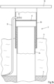
- Fig. 2a shows a hollow structural element 2 according to Fig. 1a .
- the cable arrangement 12 is in the Fig. 2a according to the Fig. 1a and in the Fig. 2b according to the Fig. 1b .
- a shading element 14 is proposed.
- the shading element 14 can be attached to the hollow structural element 2 with spacers 16.
- the cable arrangement 12 can be guided within the hollow structural element 2.
- the cable arrangement 12 can also, as in Fig. 2b shown, be arranged on the outside of the foundation structure 2a, b on the J-tube formed as a hollow structural element 2c.
- the cable arrangement 12 can be arranged in a clear width between the shading element 14 and the outer lateral surface of the foundation structure.
- the shading element 14 can be spaced from the platform 10. The shading element 14 causes the interior of the hollow structural element 2 to heat up less, so that the conductor cross sections of the cables of the cable arrangement 12 can be reduced compared to conventional arrangements.
- Fig. 2b shows a further possibility of arranging the shading element 14 directly on the platform 10.
- the shading element 14 can point radially outwards away from the platform 10. It is also possible for the shading element 14 to be inclined downwards at an angle. The length of the projection and the angle of inclination can be chosen so that the shading element 14 provides shading of the entire hollow structural element 2 essentially up to the water surface 6.
- the cable arrangement 12 is shaded by the shading element 14.
- the cable arrangement 12 can also be as in Fig. 2a shown, be arranged in the hollow structural element 2.
- Fig. 2c shows an arrangement of a hollow structural element 2c as a J-tube on the outside of the monopile 2a and/or the transition piece 2b.
- the shading element 14 is arranged directly above webs 16.
- the cable arrangement 12 is shaded in accordance with the explanations Fig. 2a , b.
- the elements of the Figs. 2a-c can be freely combined with each other.
- the founding structure according to Fig. 2c can also be a non-hollow element, e.g. a foundation.
- the structures according to Figs. 2a-c are particularly offshore structures.
- the hollow structural element 2 is described below as representative of the J-tube 2c or the monopile 2a and/or the transition piece 2b.
- Fig. 3a-d show a section through the hollow structural element 2 and the shading element 14 transversely to the longitudinal axis X, in particular perpendicular thereto.
- the high structure element 2 is tubular. Spaced from the hollow structural element 2, the shading element 14 is spanned in an arc segment with an arc angle ⁇ . The radius to a center point 2c of the shading element 14 is larger than the radius of the hollow structural element 2.
- the shading element 14 is attached to it via spacers 16 at a distance from the hollow structural element 2.
- the shading element 14 is oriented towards the south, in particular in the northern celestial sphere, but towards the north in the southern celestial sphere. This in Fig. 3a shading element 14 shown is arcuate.
- Fig. 3b shows a further shading element 14, which is straight shaped, the shading element 14 also spanning an arc angle ⁇ .
- a shading element 14 formed from two straight components that run at an angle ⁇ to each other.
- the legs of the shutdown element 14 surround the hollow structural element 2 in parts.
- Fig. 3d shows an exemplary embodiment in which the shading element 14 is arranged completely circumferentially around the hollow structural element 2.
- the shading element 14 can be formed from a sheet metal and be perforated.
- Fig. 4a shows a shading element 14 with slots 14a.
- Fig. 4b shows a shading element with holes 14b. The slots 14a and/or the holes 14b ensure good ventilation in the space between the hollow structural element 2 and the shading element 14.
- the shading element 14 can be formed in a profiled manner, in particular profiled in such a way that a distance between the shading element 14 and the hollow structural element 2 varies along the arc angle ⁇ .
- a possible exemplary embodiment is in the Fig. 5a shown.
- the surface of the shading element 15 facing the hollow structural element 2 is convexly shaped, so that a distance 20 between the hollow structural element 2 and the shading element 14 varies. It is shown that the distance 20 is smaller in a central area than in an edge area.
- Fig. 5b shows a shading element 14, which is formed in the manner of a wing in its edge regions 22. It can be seen that in the edge region 22 the distance 20 between the shading element 14 and the hollow structural element 2 varies, with initially a larger distance, which becomes smaller due to the convex shape and becomes larger again towards the central region of the shading element 14.
Landscapes
- Engineering & Computer Science (AREA)
- Mechanical Engineering (AREA)
- Sustainable Development (AREA)
- Sustainable Energy (AREA)
- Chemical & Material Sciences (AREA)
- Combustion & Propulsion (AREA)
- Life Sciences & Earth Sciences (AREA)
- General Engineering & Computer Science (AREA)
- Architecture (AREA)
- Civil Engineering (AREA)
- Structural Engineering (AREA)
- Wind Motors (AREA)
- Laying Of Electric Cables Or Lines Outside (AREA)
Description
- Der Gegenstand betrifft ein Hohlstrukturelement einer Windenergieanlage sowie eine Windenergieanlage mit einem solchen Hohlstrukturelement.
- Windenergieanlagen werden im Boden gegründet. Dies gilt vor allem für Offshore-Windenergieanlagen, die über eine Gründungsstruktur im Meeresboden verankert werden. Die Gründungsstruktur dient dann des Weiteren als Basis zum Aufbau des Turms samt Gondel und elektrischer Installationen.
- Innerhalb der Gründungsstruktur ist eine Plattform, ein sogenanntes "Airtight"-Deck angeordnet.
- Die elektrischen Energiekabel, die zur Verbindung der Windenergieanlage mit einem Energieversorgungsnetz dienen, werden entlang der Gründungsstruktur bis hin zur Plattform verlegt. In der Regel sind mehrere elektrische Kabelstränge zu einer Kabelanordnung eines Energiekabels zusammengefasst. Die elektrischen Leiter in den Kabelsträngen können einzeln isoliert sein. Die Kabelstränge können zusätzlich in einer gemeinsamen Isolation geführt sein. Die Leiterquerschnitte innerhalb der Kabelstränge werden auf theoretisch mögliche Maximalbelastungen ausgelegt. Solche Maximalbelastungen entstehen insbesondere dann, wenn einerseits die ohmschen Verluste innerhalb der Kabel groß sind und andererseits die Umgebungstemperatur an der Kabelanordnung hoch ist. Die ohmschen Verluste steigen quadratisch mit dem Strom entlang des Kabels und linear zum ohmschen Widerstand des Leiters. Zur Minimierung der ohmschen Verluste wird daher stets ein entsprechend großer Leitungsquerschnitt in den Kabelsträngen gewählt. Nachfolgend wird der Begriff Kabel ggf. sowohl für den Leiter in einem Kabelstrang, als auch den Kabelstrang und/oder die Kabelanordnung synonym genutzt.
- Hohe Ströme entlang der Kabel treten bei hohen Windstärken auf. Für den Fall, dass aufgrund starker Winde der Strom in den Leitern groß ist und gleichzeitig die Umgebungstemperatur hoch ist, beispielsweise im Sommer, wenn die Sonne ungehindert auf die Windenergieanlage einstrahlt, kann es zu erheblichen Temperaturen innerhalb der Kabelanordnung kommen. Die Leiterquerschnitte sowie die Isolation der Kabelstränge werden oftmals so dimensioniert, dass selbst unter solchen Bedingungen, das heißt maximal möglichem Strom bei maximal möglicher Sonneneinstrahlung, die Kabel nicht beschädigt werden. Oftmals geht es hierbei um die Beschädigung der elektrischen Isolationsschicht des Kabels, welche ab einer Maximaltemperatur ihre isolierende Wirkung verliert. Diese thermischen Extrembelastungen der Kabel treten jedoch nur äußerst selten auf, müssen bei deren Auslegung jedoch berücksichtigt werden. Bei dieser Auslegung kann man die Leitertemperatur durch eine Verringerung des ohmschen Widerstandes des Leiters reduzieren.
- Dazu kann man einerseits den Leiterquerschnitt erhöhen oder zu einem Leitermaterial mit kleinerem spezifischen ohmschen Widerstand übergehen: z.B. von Aluminium auf Kupfer. Beides führt zu erheblichen Mehrkosten als auch einem erheblich höheren Gewicht der Kabelanordnungen.
- Aus der
KR101720800B1 - Dem Gegenstand lag die Aufgabe zugrunde, die Anforderungen an eine Kabelanordnung einer Windenergieanlage zu reduzieren.
- Diese Aufgabe wird durch ein Hohlstrukturelement nach Anspruch 1 gelöst.
- Ein Hohlstrukturelement gemäß dem Gegenstand kann eine oben genannte Gründungsstruktur oder ein J-Tube sein.
- Die Kabelanordnung kann, wie oben beschrieben, an der Gründungstruktur entlang geführt werden . Dabei kann die Kabelanordnung innerhalb oder außerhalb der Gründungstruktur geführt werden. Auch kann die Kabelanordnung innerhalb zumindest des J-Tubes geführt sein. Ein J-Tube kann in der Gründungsstruktur oder außen an der Gründungsstruktur angeordnet sein. Insbesondere wenn das J-Tube außen an der Gründungsstruktur angeordnet ist, kann das Abschattungselement so angeordnet sein, dass das J-Tube zwischen der Gründungsstruktur und dem Abschattungselement geführt ist.
- Die Kabel werden bei Windenergieanlagen in der Regel innerhalb des Hohlstrukturelements geführt. Zwischen der Wasseroberfläche und dem Austritt des Kabels aus dem Hohlstrukturelement, insbesondere im Bereich des Airtight-Decks, treten die höchsten Temperaturen an dem Kabel auf, da die natürliche Luftzirkulation nahezu unterbunden ist. In diesem Bereich sollte das Hohlstrukturelement durch das Abschattungselement abgeschattet werden.
- Es wird vorgeschlagen, dass ein Abschattungselement an dem Hohlstrukturelement mit einem Abstand zu der Kabelanordnung angeordnet ist. Durch das Abschattungselement wird verhindert, dass die Kabelanordnung und/oder das Hohlstrukturelement, innerhalb der die Kabelanordnung geführt wird, unmittelbarer Sonneneinstrahlung, insbesondere wenn die Sonne nahe ihres Zenits ist, ausgesetzt ist. Hierdurch wird die thermische Maximalbelastung der Kabelanordnung reduziert, da selbst bei Starkwind und klarem Wetter die Kabelanordnung gegenüber herkömmlichen Anlagen einer geringeren Umgebungstemperatur ausgesetzt ist. Somit erfolgt eine bessere bzw. erhöhte Wärmeabfuhr an der Kabelanordnung durch Konvektion, da die Umgebungstemperatur gegenüber herkömmlichen Anlagen reduziert ist.
- Das Hohlstrukturelement hat eine Längsachse. Ein Schnitt quer zur Längsachse, insbesondere senkrecht zur Längsachse, kann als Querschnitt verstanden werden. Wenn nachfolgend die Formen des Abschattungselements diskutiert werden, so ist damit in der Regel ein Querschnitt in der Ebene senkrecht zur Längsachse des Hohlstrukturelements gemeint.
- Das Hohlstrukturelement kann einstückig oder mehrstückig sein. Für den Fall einer Gründungsstruktur kann das Hohlstrukturelement als Monopile gebildet sein und mit einem Übergangsstück (Transition Piece) verbunden sein oder das Übergangsstück aufweisen. Innerhalb der Gründungsstruktur, beispielsweise innerhalb des Monopiles oder des Übergangsstücks, kann eine Plattform angeordnet sein. Eine J-Tube kann an der Gründungsstruktur bis hin zur Plattform geführt sein. Dabei kann die J-Tube innerhalb oder außerhalb der Gründungsstruktur geführt sein. Eine J-Tube kann auch an einer nicht hohlen Gründungsstruktur geführt sein. Die Plattform ist dabei bevorzugt im Inneren der Gründungsstruktur angeordnet. Radial umlaufend kann darüber hinaus an der Gründungsstruktur eine Inspektionsplattform und/oder eine Landungsplattform angeordnet sein.
- Das Abschattungselement ist zusätzlich zu diesen äußeren, radial umlaufenden Plattformen vorgesehen. Im Gegensatz zu den radial umlaufenden Plattformen ist das Abschattungselement dabei nur entlang zumindest eines Teilkreisbogens an dem Hohlstrukturelement angeordnet.
- Gemäß einem Ausführungsbeispiel wird vorgeschlagen, dass das Abschattungselement bogenförmig geformt ist. Hierbei kann das Abschattungselement eine Krümmung aufweisen. Die Krümmung des Abschattungselements kann dabei geometrisch ähnlich zu der Krümmung des Hohlstrukturelements sein. Dabei ist insbesondere vorgeschlagen, dass das Abschattungselement zumindest einen Kreisbogen aufweist. Der Kreisbogen kann einen selben Mittelpunkt haben, wie ein Hohlstrukturelement und dieser kann dabei insbesondere zentrisch eines Hohlstrukturelements liegen.
- Auch ist es möglich, dass das Abschattungselement gerade ist. Im Querschnitt kann das Abschattungselement gerade verlaufen.
- Darüber hinaus ist es möglich, dass das Abschattungselement aus zumindest zwei winklig zueinander verlaufenden, geraden Abschnitten geformt ist. Der Winkel, den die beiden Abschnitte einschließen, kann das Hohlstrukturelement umgreifen.
- Erfindungsgemäß ist das Abschattungselement entlang eines Bogenabschnitts um das Hohlstrukturelement herum angeordnet.
- Der Bogenabschnitt ist kleiner als 360°. Insbesondere ist der Bogenabschnitt nur ein Teilkreisbogen. Der Bogenabschnitt hat insbesondere einen Bogenwinkel von zumindest 45°, bevorzugt zumindest 120°, insbesondere zumindest 240°. Der Bogenabschnitt umschließt insbesondere einen Winkel zwischen 90° und 150°, insbesondere einen Bereich zwischen 110° und 130°. Die genannten Bogenwinkel können ausreichend sein, um in Zeiten der maximalen Sonneneinstrahlung eine Abschattung der Kabelanordnung zu bewirken.
- Gemäß einem Ausführungsbeispiel wird vorgeschlagen, dass das Abschattungselement an einer äußeren Mantelfläche des Hohlstrukturelements angeordnet ist. Dabei können Verbindungsstege stoffschlüssig an dem Hohlstrukturelement und dem Abschattungselement angeordnet sein.
- Wie bereits erläutert kann das Hohlstrukturelement einteilig oder mehrteilig sein und als Monopile oder als Übergangsstück gebildet sein. Auch kann das Hohlstrukturelement sowohl das Monopile als auch das Übergangsstück aufweisen. Das Hohlstrukturelement kann auch als J-Tube gebildet sein.
- Gemäß einem Ausführungsbeispiel wird vorgeschlagen, dass das Abschattungselement an dem Monopile oder dem Übergangsstück angeordnet ist. Gemäß einem Ausführungsbeispiel wird vorgeschlagen, dass das Abschattungselement an der J-Tube angeordnet ist.
- Auch wird vorgeschlagen, dass das Abschattungselement das Übergangsstück kragenförmig überragt. Am Übergangsstück kann an der äußeren Mantelfläche eine umlaufende Plattform, insbesondere eine Landungsplattform angeordnet sein. An einer solchen Plattform kann das Abschattungselement zusätzlich radial nach außen weisend, kragenförmig angeordnet sein. Das Abschattungselement kann in der Höhe der Plattform (Airtight-Deck) angeordnet sein.
- Das Abschattungselement kann horizontal in radialer Richtung von dem Hohlstrukturelement fortweisen. Zusätzlich kann das Abschattungselement in axialer Richtung geneigt sein. Dabei kann das Abschattungselement nach unten, insbesondere in Richtung des Hohlstrukturelements geneigt sein.
- Den besten Effekt erzielt das Abschattungselement, wenn es zu Zeiten der maximalen Sonneneinstrahlung eine Abschattung der Kabelanordnung bewirkt. Aus diesem Grunde wird vorgeschlagen, dass das Abschattungselement im montierten Zustand des Hohlstrukturelements an der Südseite des Hohlstrukturelements angeordnet ist. Dies gilt für Installationen auf der Nordhalbkugel. Für Installationen auf der Südhalbkugel ist das Abschattungselement bevorzugt an der Nordseite des Hohlstrukturelements angeordnet.
- Das Abschattungselement ist für eine verbesserte Kühlung perforiert, insbesondere geschlitzt oder gelocht. Die Schlitze sind dabei bevorzugt rechteckig. Ihre Längsachsen verlaufen bevorzugt senkrecht zur Längsachse des Hohlstrukturelements. Dies verhindert eine Sonneneinstrahlung auf die Kabelanordnung durch die Schlitze hindurch. Die Schlitze haben bevorzugt eine breite, die kleiner ist als die doppelte Wandstärke des Abschattungselements.
- Um eine ausreichende Luftzirkulation zwischen dem Abschattungselement und dem Hohlstrukturelement und/oder der Kabelanordnung zu ermöglichen wird vorgeschlagen, dass zwischen dem Hohlstrukturelement und/oder der Kabelanordnung und dem Abschattungselement eine lichte Weite ist. Diese lichte Weite wird entlang des Bogenabschnitts variiert. Dabei ist die lichte Weite in einem Mittenbereich des Bogenabschnitts geringer, als die lichte Weite an zumindest einem äußeren Rand des Bogenabschnitts. Hierdurch wird zwischen dem Hohlstrukturelement und dem Abschattungselement ein Düseneffekt erzielt, wodurch die durchströmende Luft beschleunigt wird und so eine bessere Kühlfunktion hat.
- Gemäß einem Ausführungsbeispiel wird vorgeschlagen, dass das Abschattungselement entlang des Bogenabschnitts auf der dem Hohlstrukturelement zugewandten Seite zumindest in Teilen konvex geformt ist. Diese Form führt zu einer erhöhten Strömungsgeschwindigkeit zwischen dem Hohlstrukturelement und dem Abschattungselement. Zur Erzielung eines Tragflächeneffekts wird vorgeschlagen, dass das Abschattungselement im Bereich zumindest eines äußeren Randes des Bogenabschnittes auf der dem Hohlstrukturelement zugewandten Seite konvex geformt ist.
- An dem Hohlstrukturelement kann außen eine Plattform, insbesondere eine Landungsplattform angeordnet sein. Diese Ladungsplattform kann bereits eine Abschattung auf das Hohlstrukturelement bewirken. Zusätzlich hierzu kann das Abschattungselement vorgesehen sein. Um Material einzusparen, kann der Effekt der bereits vorhandenen Abschattung genutzt werden, in dem das Abschattungselement derart an dem Hohlstrukturelement angeordnet ist, dass im montierten Zustand des Hohlstrukturelements das Abschattungselement mit einem Abstand in Längsrichtung zu der Plattform an dem Hohlstrukturelement angeordnet ist. Dieser Abstand kann insbesondere abhängig von dem Breitengrad einer Montageposition des Windenergieanlage gewählt sein. Je höher die Sonne im Zenit steht, desto länger kann ein Schatten einer Plattform sein. Der Abstand in Längsrichtung des Hohlstrukturelements zwischen dem Abschattungselement und der Plattform kann dann größer sein.
- Gemäß einem Ausführungsbeispiel wird vorgeschlagen, dass die Kabelanordnung zwischen der Gründungsstruktur und dem Abschattungselement geführt ist.
- Das Abschattungselement ist insbesondere ein Blech, bevorzugt ein Stahlblech.
- Das Abschattungselement ist mit Abstandshaltern an dem Hohlstrukturelement befestigt, so dass eine Luftzirkulation zwischen dem Hohlstrukturelement und dem Abschattungselement möglich ist.
- Das Hohlstrukturelement ist insbesondere rohrförmig.
- Ein weiterer Aspekt ist eine Windenergieanlage nach Anspruch 14.
- Eine Windenergieanlage kann dabei eine Windkraftanlage, eine Substation, eine Konverterplattform (HGÜ Plattform), eine Umspannanlage oder dergleichen sein. Die Windenergieanlage ist insbesondere eine Offshore Anlage.
- Nachfolgend wird der Gegenstand anhand einer Ausführungsbeispiele zeigenden Zeichnung näher erläutert. In der Zeichnung zeigen:
- Fig. 1a, b
- Hohlstrukturelemente mit Kabelanordnungen;
- Fig. 2a
- ein Hohlstrukturelement mit einem Abschattungselement gemäß einem Ausführungsbeispiel;
- Fig. 2b
- ein Hohlstrukturelement mit einem Abschattungselement gemäß einem Ausführungsbeispiel;
- Fig. 2c
- ein Hohlstrukturelement mit einem Abschattungselement gemäß einem Ausführungsbeispiel;
- Fig. 3a-d
- verschiedene Anordnungen von Abschattungselementen;
- Fig. 4a, b
- Ansichten von Abschattungselementen;
- Fig. 5a, b
- Abschattungselement mit verschiedenen Strömungskonturen.
-
Fig. 1 zeigt ein Hohlstrukturelement 2 einer Windenergieanlage. Das Hohlstrukturelement 2 ist aus einem Monopile 2a sowie einem Transition Piece 2b als Gründungsstruktur gebildet. - Der Monopile 2a ist am Meeresboden 4 gegründet und ragt aus der Wasseroberfläche 6 heraus.
- Der Monopile 2a wird in den Meeresboden 4 gerammt. Dabei kann sich das Maß des Monopiles 2a verändern. Um definierte Anschlusspunkte für einen Turm der Windenergieanlage zu erhalten, ist auf dem Monopile 2a das Transition Piece 2b aufgesetzt. Das Transition Piece 2b kann in seinem inneren einen Airtight Deck 8 aufweisen. Das Airtight-Deck 8 kann als Plattform verstanden werden. Auch kann an dem Transition Piece 2b eine umlaufende, außen angeordnete Plattform 10 angeordnet sein. Die Plattform 10 kann als Landungsplattform gebildet sein. Dieser Aufbau eines Hohlstrukturelements 2 ist hinlänglich bekannt.
- Eine Kabelanordnung 12 kann aus einem oder mehreren Kabeln mit jeweils einem Isolator und einer Kabelseele aus einem elektrischen Leiter gebildet sein. Die Kabel können in der Kabelanordnung 12 in einer gemeinsamen Hülle, insbesondere einer gemeinsamen Isolation geführt sein.
- In der
Fig. 1a ist gezeigt, dass die Kabelanordnung 12 unterhalb der Wasseroberfläche 6 in das Innere des Hohlstrukturelements 2 hineingeführt ist und im Inneren des Hohlstrukturelements 2 bis hin zum Airtight-Deck 8 geführt wird. Ausgehend vom Airtight-Deck 8 erfolgt eine elektrische Kontaktierung der Kabel der Kabelanordnung 12 in an sich bekannter Art und Weise mit an sich bekannter Leistungselektronik. - Über die Kabel der Kabelanordnung 12 wird die von der Windenergieanlage 2 erzeugte elektrische Energie hin zu einem Energieversorgungsnetz transportiert. Dabei fließt über die Kabel der Kabelanordnung 12 erhebliche elektrische Leistung. Die dadurch bedingten hohen Ströme verursachen joulesche Verluste, die proportional zum ohmschen Widerstand der jeweiligen Leiter sind. Zur Reduktion des ohmschen Widerstands werden die Leiterquerschnitte groß gewählt.
- Die entstehenden ohmschen Verluste müssten über Konvektion an die Umgebung abgegeben werden, um zu verhindern, dass sich die Kabelanordnung 12 so stark aufheizt, dass es zu Beschädigungen kommt.
- Zwischen der Wasseroberfläche 6 und dem Airtight-Deck 8 ist der Luftaustausch innerhalb des Hohlstrukturelements 2 jedoch stark einschränkt, wenn nicht gar ausgeschlossen. Dadurch heizt sich der Innenraum des Hohlstrukturelements 2 auf und die ohmschen Verluste innerhalb der Kabel der Kabelanordnung 12 können nicht mehr gut abgeleitet werden.
- Kommt es zu Zeiten von Starkwind zu großen elektrischen Leistungen, die über die Kabelanordnung 12 transportiert werden, heizen sich die Kabel der Kabelanordnung 12 besonders auf. Kommt es dann zusätzlich zu starker Sonneneinstrahlung auf das Hohlstrukturelement 2, so heizt der Innenraum des Hohlstrukturelements 2 zwischen der Wasseroberfläche 6 und dem Airtight-Deck 8 erheblich auf. Auch solche extremen Bedingungen müssen berücksichtigt werden, wenn die Leiterquerschnitte der Kabel der Kabelanordnung 12 dimensioniert werden.
- Um die Leiterquerschnitte geringer dimensionieren zu können, wird vorgeschlagen, dass Hohlstrukturelement 2 abzuschatten, wie nachfolgend noch gezeigt werden wird.
-
Fig. 1b zeigt ein Hohlstrukturelement 2c, welches als J-Tube gebildet ist. Im Unterschied zu derFig. 1a ist in derFig. 1b die Kabelanordnung 12 in der J-Tube außerhalb der Gründungsstruktur geführt. Auch die J-Tube umschließt die Kabelanordnung 12 vollständig, so dass es ähnlich wie zuvor beschrieben, auch innerhalb der J-Tube zu erheblicher Wärmeentwicklung führen kann. Kommt es zu direkter Sonneneinstrahlung auf die J-Tubes, treten erhebliche Temperaturen innerhalb der Kabel der Kabelanordnung 12 auf. Auch hierzu wird eine Abschattung wie nachfolgend beschrieben vorgeschlagen. Das Hohlstrukturelement 2c kann auch (nicht gezeigt) innerhalb des Monopiles 2a und/oder des Transition Pieces 2b geführt sein. -
Fig. 2a zeigt ein Hohlstrukturelement 2 entsprechend derFig. 1a . Die Kabelanordnung 12 ist in derFig. 2a gemäß derFig. 1a und in derFig. 2b gemäß derFig. 1b . - Zur Vermeidung von Sonneneinstrahlung, insbesondere wenn die Sonne nahe ihres Zenits ist, wird ein Abschattungselement 14 vorgeschlagen. Das Abschattungselement 14 kann mit Abstandshaltern 16 an dem Hohlstrukturelement 2 befestigt sein. Die Kabelanordnung 12 kann innerhalb des Hohlstrukturelements 2 geführt sein. Die Kabelanordnung 12 kann auch, wie in
Fig. 2b gezeigt, außen an der Gründungsstruktur 2a,b an der als Hohlstrukturelement 2 c gebildeten J-Tube angeordnet sein. Dabei kann die Kabelanordnung 12 in einer lichten Weite zwischen dem Abschattungselement 14 und der äußeren Mantelfläche der Gründungsstruktur angeordnet sein. - Steht die Sonne nahe ihres Zenits, so strahlt sie im Winkel α auf das Hohlstrukturelement 2. Bedingt durch die nach außen kragende Plattform 10 ist ein Bereich zwischen der Plattform 10 und der Oberkante des Abschattungselements 14 bereits abgeschattet. In diesem Abstand entlang der Längsachse X des Hohlstrukturelements 2 kann das Abschattungselement 14 von der der Plattform 10 beabstandet sein. Durch das Abschattungselement 14 wird bewirkt, dass das Innere des Hohlstrukturelements 2 weniger aufheizt, sodass die Leiterquerschnitte der Kabel der Kabelanordnung 12 gegenüber herkömmlichen Anordnungen reduziert sein können.
-
Fig. 2b zeigt eine weitere Möglichkeit der Anordnung des Abschattungselements 14 unmittelbar an der Plattform 10. Das Abschattungselement 14 kann radial nach außen von der Plattform 10 weg weisen. Auch ist es möglich, dass das Abschattungselement 14 winklig nach unten geneigt ist. Die Länge der Auskragung sowie der Neigungswinkel kann so gewählt werden, dass durch das Abschattungselement 14 eine Abschattung des gesamten Hohlstrukturelements 2 bis im Wesentlichen hin zur Wasseroberfläche 6 bewirkt wird. Die Kabelanordnung 12 ist durch das Abschattungselement 14 abgeschattet. Die Kabelanordnung 12 kann auch wie inFig. 2a gezeigt, in dem Hohlstrukturelement 2 angeordnet sein. -
Fig. 2c zeigt eine Anordnung eines Hohlstrukturelements 2c als J-Tube außen an dem Monopile 2a und/oder dem Transition Piece 2b. An der J-Tube ist das Abschattungselement 14 unmittelbar über Stege 16 angeordnet. Die Abschattung der Kabelanordnung 12 erfolgt entsprechend den Ausführungen zuFig. 2a , b. Die Elemente derFigs. 2a-c lassen sich frei miteinander kombinieren. Die Gründungsstruktur gemäßFig. 2c kann auch ein nicht hohles Element, z.B. ein Fundament sein. Die Strukturen gemäßFigs. 2a-c sind insbesondere Offshore Strukturen. - Nachfolgend wird das Hohlstrukturelement 2 stellvertretend für die J-Tube 2c oder das Monopile 2a und/oder das Transition Piece 2b beschrieben.
- Die
Fig. 3a-d zeigen einen Schnitt durch das Hohlstrukturelement 2 und das Abschattungselement 14 quer zur Längsachse X, insbesondere senkrecht hierzu. - In
Fig. 3a zu erkennen ist, dass das Hochstrukturelement 2 rohrförmig ist. Beabstandet von dem Hohlstrukturelement 2 ist das Abschattungselement 14 in einem Bogensegment mit einem Bogenwinkel β aufgespannt. Der Radius zu einem Mittelpunkt 2c des Abschattungselements 14 ist größer als der Radius des Hohlstrukturelements 2. - Das Abschattungselement 14 ist über Abstandshalter 16 beabstandet von dem Hohlstrukturelement 2 daran befestigt.
- Das Abschattungselement 14 ist insbesondere in der nördlichen Himmelsphäre Richtung Süden ausgerichtet, hingegen in der südlichen Himmelsphäre Richtung Norden ausgerichtet. Das in
Fig. 3a gezeigte Abschattungselement 14 ist bogenförmig. -
Fig. 3b zeigt ein weiteres Abschattungselement 14, welches gerade geformt ist, wobei das Abschattungselement 14 ebenfalls einen Bogenwinkel β aufspannt. - In der
Fig. 3c ist ein Abschattungselement 14 aus zwei geraden Bauelementen, die in einem Winkel γ zueinander verlaufen, gebildet. Die Schenkel des Abschaltungselements 14 umgreifen das Hohlstrukturelement 2 in Teilen. -
Fig. 3d zeigt ein Ausführungsbeispiel, bei dem das Abschattungselement 14 vollständig umlaufend um das Hohlstrukturelement 2 angeordnet ist. - Wie bereits erläutert, kann das Abschattungselement 14 aus einem Blech gebildet sein und perforiert sein.
Fig. 4a zeigt ein Abschattungselement 14 mit Schlitzen 14a.Fig. 4b zeigt ein Abschattungselement mit Löchern 14b. Die Schlitze 14a und/oder die Löcher 14b sorgen für eine gute Belüftung in dem Zwischenraum zwischen dem Hohlstrukturelement 2 und dem Abschattungselement 14. - Das Abschattungselement 14 kann profiliert gebildet sein, insbesondere so profiliert, dass ein Abstand zwischen dem Abschattungselement 14 und dem Hohlstrukturelement 2 entlang des Bogenwinkels β variiert. Ein mögliches Ausführungsbeispiel ist in der
Fig. 5a gezeigt. Hier ist die dem Hohlstrukturelement 2 zugewandte Oberfläche des Abschattungselements 15 konvex geformt, so dass ein Abstand 20 zwischen dem Hohlstrukturelement 2 und dem Abschattungselement 14 variiert. Gezeigt ist, dass der Abstand 20 in einem Mittenbereich geringer ist, als in einem Randbereich. -
Fig. 5b zeigt ein Abschattungselement 14, welches in seinen Randbereichen 22 in der Art eines Flügels gebildet ist. Zu erkennen ist, dass im Randbereich 22 der Abstand 20 zwischen dem Abschattungselement 14 und dem Hohlstrukturelement 2 variiert, wobei zunächst ein größerer Abstand gegeben ist, dieser aufgrund der konvexen Form kleiner wird und hin zum Mittenbereich des Abschattungselements 14 wieder größer wird. - Durch die beiden Profilierungen wie in den
Fig. 5a und b gezeigt, ist der Kühleffekt der zirkulierenden Luft zwischen dem Hohlstrukturelement 2 und dem Abschattungselement 14 vergrößert, da die Strömungsgeschwindigkeiten vorbeiströmender Luft erhöht werden. -
- 2
- Hohlstrukturelement
- 2a
- Monopile
- 2b
- Transition Piece
- 2c
- J-Tube
- 2c
- Mittelpunkt
- 4
- Meeresboden
- 6
- Wasseroberfläche
- 8
- Airtight-Deck
- 10
- Plattform
- 12
- Kabelanordnung
- 14
- Abschattungselement
- 14a
- Schlitz
- 14b
- Loch
- 16
- Abstandshalter
- 18
- Bereich
- 20
- Abstand
- 22
- Randbereich
Claims (14)
- Hohlstrukturelement (2) einer Windenergieanlage, insbesondere einer Offshore-Windenergieanlage, umfassend:- ein Hohlstrukturelement (2), und- eine entlang des Hohlstrukturelements (2) verlaufende Kabelanordnung (12), wobei- ein Abschattungselement (14) an dem Hohlstrukturelement (2) mit einem Abstand zu der Kabelanordnung (12) angeordnet ist,
dadurch gekennzeichnet,- dass das Abschattungselement (14) entlang eines Bogenabschnitts um das Hohlstrukturelement (2) herum angeordnet ist und eine lichte Weite zwischen dem Hohlstrukturelement (2) und dem Abschattungselement (14) entlang des Bogenabschnitts derart variiert, dass die lichte Weite in einem Mittenbereich des Bogenabschnitts geringer ist, als die lichte Weite an zumindest einem äußeren Rand des Bogenabschnitts. - Hohlstrukturelement (2) nach Anspruch 1,
dadurch gekennzeichnet,- dass das Abschattungselement (14) bogenförmig geformt ist, wobei das Abschattungselement (14) eine Krümmung aufweist, insbesondere dass das Abschattungselement (14) zumindest einen Kreisbogen aufweist oder- dass das Abschattungselement (14) gerade ist oder- dass das Abschattungselement (14) aus zumindest zwei winklig zueinander verlaufenden, geraden Abschnitten geformt ist, wobei der Winkel zwischen den geraden Abschnitten das Hohlstrukturelement (2) umgreift. - Hohlstrukturelement (2) nach einem der vorangehenden Ansprüche,
dadurch gekennzeichnet,- dass der Bogenabschnitt einen Bogenwinkel von zumindest 45° bevorzugt zumindest 120, insbesondere zumindest 240°, insbesondere zwischen 90° und 150°, insbesondere im Bereich zwischen 110° und 130° umschließt. - Hohlstrukturelement (2) nach einem der vorangehenden Ansprüche,
dadurch gekennzeichnet,- dass das Abschattungselement (14) an einer äußeren Mantelfläche des Hohlstrukturelements (2) angeordnet ist und/oder- dass das Abschattungselement (14) mit Abstandshaltern (16) an dem Hohlstrukturelement (2) befestigt ist. - Hohlstrukturelement (2) nach einem der vorangehenden Ansprüche,
dadurch gekennzeichnet,- dass das Hohlstrukturelement (2) ein Monopile (2a) und/oder ein Übergangsstück aufweist und/oder eine J-Tube (2c) ist. - Hohlstrukturelement (2) nach einem der vorangehenden Ansprüche,
dadurch gekennzeichnet,- dass das Abschattungselement (14) an dem Monopile (2a) oder dem Übergangsstück angeordnet ist. - Hohlstrukturelement (2) nach einem der vorangehenden Ansprüche,
dadurch gekennzeichnet,- dass das Abschattungselement (14) das Hohlstrukturelement (2) kragenförmig überragt, insbesondere dass das Abschattungselement (14) das Hohlstrukturelement (2) radial nach außen überragt insbesondere im Bereich einer Plattform (10) und/oder dass das Abschattungselement (14) in Richtung des Hohlstrukturelements (2) geneigt ist. - Hohlstrukturelement (2) nach einem der vorangehenden Ansprüche,
dadurch gekennzeichnet,- dass das Abschattungselement (14) im montierten Zustand an der Südseite des Hohlstrukturelements (2) angeordnet ist.und/oder- dass das Abschattungselement (14) perforiert, insbesondere geschlitzt und/oder gelocht ist. - Hohlstrukturelement (2) nach einem der vorangehenden Ansprüche,
dadurch gekennzeichnet,- dass das Abschattungselement (14) entlang des Bogenabschnitts auf der dem Hohlstrukturelement (2) zugewandten Seite zumindest in Teilen konvex geformt ist, insbesondere dass das Abschattungselement (14) im Bereich zumindest eines äußeren Randes des Bogenabschnitts auf der dem Hohlstrukturelement (2) zugewandten Seite konvex geformt ist. - Hohlstrukturelement (2) nach einem der vorangehenden Ansprüche,
dadurch gekennzeichnet,- dass das Abschattungselement (14) derart an dem Hohlstrukturelement (2) angeordnet ist, dass im montierten Zustand des Hohlstrukturelements (2) das Abschattungselement (14) mit einem Abstand in Längsrichtung zu einer Plattform (10) an dem Hohlstrukturelement (2) angeordnet ist, insbesondere dass der Abstand abhängig von einem Breitengrad einer Montageposition des Hohlstrukturelements (2) gewählt ist. - Hohlstrukturelement (2) nach einem der vorangehenden Ansprüche,
dadurch gekennzeichnet,- dass die Kabelanordnung (12) innerhalb des Hohlstrukturelements (2) und/oder zwischen dem Hohlstrukturelement (2) und dem Abschattungselement (14) geführt ist. - Hohlstrukturelement (2) nach einem der vorangehenden Ansprüche,
dadurch gekennzeichnet,- dass das Abschattungselement (14) aus einem Blech gebildet ist. - Hohlstrukturelement (2) nach einem der vorangehenden Ansprüche,
dadurch gekennzeichnet,- dass das Hohlstrukturelement (2) rohrförmig ist. - Windenergieanlage, insbesondere Offshore-Windenergieanlage mit einem Hohlstrukturelement (2) nach einem der vorangehenden Ansprüche.
Applications Claiming Priority (2)
| Application Number | Priority Date | Filing Date | Title |
|---|---|---|---|
| DE102019114655.0A DE102019114655A1 (de) | 2019-05-31 | 2019-05-31 | Hohlstrukturelement einer Windenergieanlage |
| PCT/EP2020/063153 WO2020239427A1 (de) | 2019-05-31 | 2020-05-12 | Hohlstrukturelement einer windenergieanlage |
Publications (3)
| Publication Number | Publication Date |
|---|---|
| EP3976962A1 EP3976962A1 (de) | 2022-04-06 |
| EP3976962B1 true EP3976962B1 (de) | 2023-12-06 |
| EP3976962C0 EP3976962C0 (de) | 2023-12-06 |
Family
ID=70775332
Family Applications (1)
| Application Number | Title | Priority Date | Filing Date |
|---|---|---|---|
| EP20726738.6A Active EP3976962B1 (de) | 2019-05-31 | 2020-05-12 | Hohlstrukturelement einer windenergieanlage |
Country Status (6)
| Country | Link |
|---|---|
| US (1) | US11585095B2 (de) |
| EP (1) | EP3976962B1 (de) |
| JP (1) | JP7187718B2 (de) |
| KR (1) | KR102449756B1 (de) |
| DE (1) | DE102019114655A1 (de) |
| WO (1) | WO2020239427A1 (de) |
Families Citing this family (2)
| Publication number | Priority date | Publication date | Assignee | Title |
|---|---|---|---|---|
| EP4184005A1 (de) | 2021-11-23 | 2023-05-24 | Siemens Gamesa Renewable Energy A/S | Käfig für einen monopile einer offshore-windturbine, turm für eine offshore-windturbine, offshore-windturbine und verfahren zur installation eines turmes einer offshore-windturbine |
| JP7629385B2 (ja) * | 2021-11-25 | 2025-02-13 | 鹿島建設株式会社 | グラウト注入装置 |
Citations (3)
| Publication number | Priority date | Publication date | Assignee | Title |
|---|---|---|---|---|
| WO2011033267A2 (en) * | 2009-09-19 | 2011-03-24 | Matthew Bristow | A method of forming and installing a j-tube system |
| WO2015071680A1 (en) * | 2013-11-15 | 2015-05-21 | Tekmar Energy Limited | Cable installation and/or protection apparatus and associated method |
| KR101720800B1 (ko) * | 2011-03-04 | 2017-04-11 | 엘에스전선 주식회사 | J튜브의 태양열 차단장치 |
Family Cites Families (12)
| Publication number | Priority date | Publication date | Assignee | Title |
|---|---|---|---|---|
| DE202005004917U1 (de) * | 2005-03-23 | 2005-07-21 | Schmidlin Deutschland Gmbh | Flächiges Traggerüst mit fassadenintegrierter Photovoltaik an einem Turm einer Windkraftanlage |
| JP3155370U (ja) | 2009-09-03 | 2009-11-12 | 株式会社Ntec | 橋梁添架管路の日覆い構造 |
| JP2012102692A (ja) | 2010-11-12 | 2012-05-31 | Hitachi Industrial Equipment Systems Co Ltd | 風力発電用変圧器及び風力発電用変圧器を搭載する風力発電設備 |
| WO2013044977A1 (en) * | 2011-09-30 | 2013-04-04 | Seahorn Energy Holding ApS | A wall element system for an offshore power storage facility |
| KR101362794B1 (ko) * | 2012-05-22 | 2014-02-24 | 박기주 | 계통 연계형 배전반용 접속함 |
| CN103775288B (zh) * | 2014-01-27 | 2017-02-15 | 华北水利水电大学 | 靠钢结构复合塔体提供稳定电源的风力发电系统 |
| DE102014206000A1 (de) | 2014-03-31 | 2015-10-01 | Siemens Aktiengesellschaft | Kühlvorrichtung |
| CN105098670B (zh) * | 2015-07-10 | 2018-07-27 | 新疆金风科技股份有限公司 | 基于围护结构的传热散热系统和风力发电机组 |
| DE102015217035A1 (de) * | 2015-09-04 | 2017-03-09 | Wobben Properties Gmbh | Windenergieanlage und Verfahren zum Steuern einer Kühlung einer Windenergieanlage |
| EP4651326A3 (de) * | 2016-11-28 | 2026-01-14 | Ørsted Wind Power A/S | Führungsvorrichtung |
| WO2018162103A1 (en) * | 2017-03-09 | 2018-09-13 | Siemens Wind Power A/S | Cable hang-off arrangement |
| DE102018125323A1 (de) * | 2018-10-12 | 2020-04-16 | Innogy Se | Windkraftanlage |
-
2019
- 2019-05-31 DE DE102019114655.0A patent/DE102019114655A1/de not_active Withdrawn
-
2020
- 2020-05-12 KR KR1020217038605A patent/KR102449756B1/ko active Active
- 2020-05-12 WO PCT/EP2020/063153 patent/WO2020239427A1/de not_active Ceased
- 2020-05-12 JP JP2021570736A patent/JP7187718B2/ja active Active
- 2020-05-12 EP EP20726738.6A patent/EP3976962B1/de active Active
-
2021
- 2021-11-22 US US17/532,628 patent/US11585095B2/en active Active
Patent Citations (3)
| Publication number | Priority date | Publication date | Assignee | Title |
|---|---|---|---|---|
| WO2011033267A2 (en) * | 2009-09-19 | 2011-03-24 | Matthew Bristow | A method of forming and installing a j-tube system |
| KR101720800B1 (ko) * | 2011-03-04 | 2017-04-11 | 엘에스전선 주식회사 | J튜브의 태양열 차단장치 |
| WO2015071680A1 (en) * | 2013-11-15 | 2015-05-21 | Tekmar Energy Limited | Cable installation and/or protection apparatus and associated method |
Also Published As
| Publication number | Publication date |
|---|---|
| EP3976962A1 (de) | 2022-04-06 |
| US20220081911A1 (en) | 2022-03-17 |
| JP7187718B2 (ja) | 2022-12-12 |
| US11585095B2 (en) | 2023-02-21 |
| KR102449756B1 (ko) | 2022-09-30 |
| EP3976962C0 (de) | 2023-12-06 |
| DE102019114655A1 (de) | 2020-12-03 |
| JP2022529386A (ja) | 2022-06-21 |
| KR20220002510A (ko) | 2022-01-06 |
| WO2020239427A1 (de) | 2020-12-03 |
Similar Documents
| Publication | Publication Date | Title |
|---|---|---|
| EP1658408B1 (de) | Turm für eine windenergieanlage | |
| EP1071883B1 (de) | Windenergieanlage mit transformator | |
| EP4013961B1 (de) | Schwimmende windenergieanlage mit integriertem umspannwerk | |
| EP2270404B1 (de) | Schwimmfähige Plattform zur Anordnung von Solarmodulen auf einem Gewässer | |
| Preeti et al. | Analysis of transmission towers with different configurations | |
| WO2020239427A1 (de) | Hohlstrukturelement einer windenergieanlage | |
| WO2016046046A1 (de) | Übergangsstück für windenergieanlagen und anschlussbauwerke | |
| WO2017045993A1 (de) | Turm für eine windkraftanlage | |
| DE1615929A1 (de) | Aufbau eines Mehrphasen-Tiefsttemperatur-Kabels | |
| DE102018122638A1 (de) | Windenergieanlagen-Turmsegment für einen Windenergieanlagen-Turm und Verfahren | |
| EP3560051B1 (de) | Umspannstation, verfahren und vorrichtung für eine umspannstation | |
| EP2935880B1 (de) | Verfahren zur ableitung der elektrischen energie eines blitzschlags bei einer windenergieanlage und windenergieanlage | |
| EP4361435A1 (de) | Windkraftanlage mit vertikaler achse | |
| EP4261410B1 (de) | Windkraftanlage mit stromschienenanordnung | |
| AT412808B (de) | Hochspannungsmast | |
| DE4201425C2 (de) | Flügel für ein Windrad bzw. einen Rotor | |
| EP4069971A1 (de) | Übergangsstück für einen turm einer windenergieanlage und turm einer windenergieanlage | |
| EP4116572B1 (de) | Energieumwandlungssystem zum umwandeln von windenergie in elektrische energie | |
| WO2007042292A1 (de) | Kabelstütze | |
| EP2302278B1 (de) | Halter für eine Außenkonstruktion an einem Fallrohr | |
| DE10125140A1 (de) | Wind- und Solarkraftwerk | |
| DE102016219048A1 (de) | Einrichtung zum Transport von elektrischer Energie von einer oben an einem Tragwerk befindlichen Einheit nach unten zum Fuß des Tragwerks | |
| WO2021233610A1 (de) | Energieübertragung in einer windkraftanlage | |
| WO2017076665A1 (de) | Freileitungsmastsystem und verfahren zum erweitern der elektrischen übertragungskapazität eines freileitungsmastsystems | |
| DE102005008843A1 (de) | Schwenkende Windhaube für Höhenbau |
Legal Events
| Date | Code | Title | Description |
|---|---|---|---|
| STAA | Information on the status of an ep patent application or granted ep patent |
Free format text: STATUS: UNKNOWN |
|
| STAA | Information on the status of an ep patent application or granted ep patent |
Free format text: STATUS: THE INTERNATIONAL PUBLICATION HAS BEEN MADE |
|
| TPAC | Observations filed by third parties |
Free format text: ORIGINAL CODE: EPIDOSNTIPA |
|
| PUAI | Public reference made under article 153(3) epc to a published international application that has entered the european phase |
Free format text: ORIGINAL CODE: 0009012 |
|
| STAA | Information on the status of an ep patent application or granted ep patent |
Free format text: STATUS: REQUEST FOR EXAMINATION WAS MADE |
|
| 17P | Request for examination filed |
Effective date: 20211115 |
|
| AK | Designated contracting states |
Kind code of ref document: A1 Designated state(s): AL AT BE BG CH CY CZ DE DK EE ES FI FR GB GR HR HU IE IS IT LI LT LU LV MC MK MT NL NO PL PT RO RS SE SI SK SM TR |
|
| DAV | Request for validation of the european patent (deleted) | ||
| DAX | Request for extension of the european patent (deleted) | ||
| STAA | Information on the status of an ep patent application or granted ep patent |
Free format text: STATUS: EXAMINATION IS IN PROGRESS |
|
| 17Q | First examination report despatched |
Effective date: 20221202 |
|
| GRAP | Despatch of communication of intention to grant a patent |
Free format text: ORIGINAL CODE: EPIDOSNIGR1 |
|
| STAA | Information on the status of an ep patent application or granted ep patent |
Free format text: STATUS: GRANT OF PATENT IS INTENDED |
|
| RAP1 | Party data changed (applicant data changed or rights of an application transferred) |
Owner name: RWE OFFSHORE WIND GMBH |
|
| INTG | Intention to grant announced |
Effective date: 20230718 |
|
| GRAS | Grant fee paid |
Free format text: ORIGINAL CODE: EPIDOSNIGR3 |
|
| GRAA | (expected) grant |
Free format text: ORIGINAL CODE: 0009210 |
|
| STAA | Information on the status of an ep patent application or granted ep patent |
Free format text: STATUS: THE PATENT HAS BEEN GRANTED |
|
| AK | Designated contracting states |
Kind code of ref document: B1 Designated state(s): AL AT BE BG CH CY CZ DE DK EE ES FI FR GB GR HR HU IE IS IT LI LT LU LV MC MK MT NL NO PL PT RO RS SE SI SK SM TR |
|
| REG | Reference to a national code |
Ref country code: GB Ref legal event code: FG4D Free format text: NOT ENGLISH |
|
| REG | Reference to a national code |
Ref country code: CH Ref legal event code: EP |
|
| REG | Reference to a national code |
Ref country code: DE Ref legal event code: R096 Ref document number: 502020006306 Country of ref document: DE |
|
| REG | Reference to a national code |
Ref country code: IE Ref legal event code: FG4D Free format text: LANGUAGE OF EP DOCUMENT: GERMAN |
|
| U01 | Request for unitary effect filed |
Effective date: 20240105 |
|
| U07 | Unitary effect registered |
Designated state(s): AT BE BG DE DK EE FI FR IT LT LU LV MT NL PT SE SI Effective date: 20240117 |
|
| REG | Reference to a national code |
Ref country code: NO Ref legal event code: T2 Effective date: 20231206 |
|
| REG | Reference to a national code |
Ref country code: GR Ref legal event code: EP Ref document number: 20240400270 Country of ref document: GR Effective date: 20240312 |
|
| PG25 | Lapsed in a contracting state [announced via postgrant information from national office to epo] |
Ref country code: ES Free format text: LAPSE BECAUSE OF FAILURE TO SUBMIT A TRANSLATION OF THE DESCRIPTION OR TO PAY THE FEE WITHIN THE PRESCRIBED TIME-LIMIT Effective date: 20231206 |
|
| PG25 | Lapsed in a contracting state [announced via postgrant information from national office to epo] |
Ref country code: ES Free format text: LAPSE BECAUSE OF FAILURE TO SUBMIT A TRANSLATION OF THE DESCRIPTION OR TO PAY THE FEE WITHIN THE PRESCRIBED TIME-LIMIT Effective date: 20231206 |
|
| PG25 | Lapsed in a contracting state [announced via postgrant information from national office to epo] |
Ref country code: RS Free format text: LAPSE BECAUSE OF FAILURE TO SUBMIT A TRANSLATION OF THE DESCRIPTION OR TO PAY THE FEE WITHIN THE PRESCRIBED TIME-LIMIT Effective date: 20231206 Ref country code: HR Free format text: LAPSE BECAUSE OF FAILURE TO SUBMIT A TRANSLATION OF THE DESCRIPTION OR TO PAY THE FEE WITHIN THE PRESCRIBED TIME-LIMIT Effective date: 20231206 |
|
| U20 | Renewal fee for the european patent with unitary effect paid |
Year of fee payment: 5 Effective date: 20240516 |
|
| PG25 | Lapsed in a contracting state [announced via postgrant information from national office to epo] |
Ref country code: IS Free format text: LAPSE BECAUSE OF FAILURE TO SUBMIT A TRANSLATION OF THE DESCRIPTION OR TO PAY THE FEE WITHIN THE PRESCRIBED TIME-LIMIT Effective date: 20240406 |
|
| PG25 | Lapsed in a contracting state [announced via postgrant information from national office to epo] |
Ref country code: CZ Free format text: LAPSE BECAUSE OF FAILURE TO SUBMIT A TRANSLATION OF THE DESCRIPTION OR TO PAY THE FEE WITHIN THE PRESCRIBED TIME-LIMIT Effective date: 20231206 |
|
| PG25 | Lapsed in a contracting state [announced via postgrant information from national office to epo] |
Ref country code: SK Free format text: LAPSE BECAUSE OF FAILURE TO SUBMIT A TRANSLATION OF THE DESCRIPTION OR TO PAY THE FEE WITHIN THE PRESCRIBED TIME-LIMIT Effective date: 20231206 |
|
| PG25 | Lapsed in a contracting state [announced via postgrant information from national office to epo] |
Ref country code: SM Free format text: LAPSE BECAUSE OF FAILURE TO SUBMIT A TRANSLATION OF THE DESCRIPTION OR TO PAY THE FEE WITHIN THE PRESCRIBED TIME-LIMIT Effective date: 20231206 Ref country code: SK Free format text: LAPSE BECAUSE OF FAILURE TO SUBMIT A TRANSLATION OF THE DESCRIPTION OR TO PAY THE FEE WITHIN THE PRESCRIBED TIME-LIMIT Effective date: 20231206 Ref country code: RO Free format text: LAPSE BECAUSE OF FAILURE TO SUBMIT A TRANSLATION OF THE DESCRIPTION OR TO PAY THE FEE WITHIN THE PRESCRIBED TIME-LIMIT Effective date: 20231206 Ref country code: IS Free format text: LAPSE BECAUSE OF FAILURE TO SUBMIT A TRANSLATION OF THE DESCRIPTION OR TO PAY THE FEE WITHIN THE PRESCRIBED TIME-LIMIT Effective date: 20240406 Ref country code: CZ Free format text: LAPSE BECAUSE OF FAILURE TO SUBMIT A TRANSLATION OF THE DESCRIPTION OR TO PAY THE FEE WITHIN THE PRESCRIBED TIME-LIMIT Effective date: 20231206 |
|
| PG25 | Lapsed in a contracting state [announced via postgrant information from national office to epo] |
Ref country code: PL Free format text: LAPSE BECAUSE OF FAILURE TO SUBMIT A TRANSLATION OF THE DESCRIPTION OR TO PAY THE FEE WITHIN THE PRESCRIBED TIME-LIMIT Effective date: 20231206 |
|
| PG25 | Lapsed in a contracting state [announced via postgrant information from national office to epo] |
Ref country code: PL Free format text: LAPSE BECAUSE OF FAILURE TO SUBMIT A TRANSLATION OF THE DESCRIPTION OR TO PAY THE FEE WITHIN THE PRESCRIBED TIME-LIMIT Effective date: 20231206 |
|
| REG | Reference to a national code |
Ref country code: DE Ref legal event code: R097 Ref document number: 502020006306 Country of ref document: DE |
|
| PLBE | No opposition filed within time limit |
Free format text: ORIGINAL CODE: 0009261 |
|
| STAA | Information on the status of an ep patent application or granted ep patent |
Free format text: STATUS: NO OPPOSITION FILED WITHIN TIME LIMIT |
|
| 26N | No opposition filed |
Effective date: 20240909 |
|
| REG | Reference to a national code |
Ref country code: CH Ref legal event code: PL |
|
| PG25 | Lapsed in a contracting state [announced via postgrant information from national office to epo] |
Ref country code: MC Free format text: LAPSE BECAUSE OF FAILURE TO SUBMIT A TRANSLATION OF THE DESCRIPTION OR TO PAY THE FEE WITHIN THE PRESCRIBED TIME-LIMIT Effective date: 20231206 |
|
| PG25 | Lapsed in a contracting state [announced via postgrant information from national office to epo] |
Ref country code: MC Free format text: LAPSE BECAUSE OF FAILURE TO SUBMIT A TRANSLATION OF THE DESCRIPTION OR TO PAY THE FEE WITHIN THE PRESCRIBED TIME-LIMIT Effective date: 20231206 Ref country code: CH Free format text: LAPSE BECAUSE OF NON-PAYMENT OF DUE FEES Effective date: 20240531 |
|
| U20 | Renewal fee for the european patent with unitary effect paid |
Year of fee payment: 6 Effective date: 20250516 |
|
| PGFP | Annual fee paid to national office [announced via postgrant information from national office to epo] |
Ref country code: NO Payment date: 20250520 Year of fee payment: 6 |
|
| PGFP | Annual fee paid to national office [announced via postgrant information from national office to epo] |
Ref country code: GR Payment date: 20250519 Year of fee payment: 6 |
|
| PGFP | Annual fee paid to national office [announced via postgrant information from national office to epo] |
Ref country code: IE Payment date: 20250522 Year of fee payment: 6 |
|
| PG25 | Lapsed in a contracting state [announced via postgrant information from national office to epo] |
Ref country code: CY Free format text: LAPSE BECAUSE OF FAILURE TO SUBMIT A TRANSLATION OF THE DESCRIPTION OR TO PAY THE FEE WITHIN THE PRESCRIBED TIME-LIMIT; INVALID AB INITIO Effective date: 20200512 |
|
| PG25 | Lapsed in a contracting state [announced via postgrant information from national office to epo] |
Ref country code: HU Free format text: LAPSE BECAUSE OF FAILURE TO SUBMIT A TRANSLATION OF THE DESCRIPTION OR TO PAY THE FEE WITHIN THE PRESCRIBED TIME-LIMIT; INVALID AB INITIO Effective date: 20200512 |
|
| PGFP | Annual fee paid to national office [announced via postgrant information from national office to epo] |
Ref country code: GB Payment date: 20260325 Year of fee payment: 7 |