EP3976937B1 - Teil für einen turbomaschinenzentrifugalentgaser mit angepassten longitudinalen wänden - Google Patents
Teil für einen turbomaschinenzentrifugalentgaser mit angepassten longitudinalen wänden Download PDFInfo
- Publication number
- EP3976937B1 EP3976937B1 EP20737254.1A EP20737254A EP3976937B1 EP 3976937 B1 EP3976937 B1 EP 3976937B1 EP 20737254 A EP20737254 A EP 20737254A EP 3976937 B1 EP3976937 B1 EP 3976937B1
- Authority
- EP
- European Patent Office
- Prior art keywords
- longitudinal walls
- enclosure
- oil
- component
- mixture
- Prior art date
- Legal status (The legal status is an assumption and is not a legal conclusion. Google has not performed a legal analysis and makes no representation as to the accuracy of the status listed.)
- Active
Links
- 239000000203 mixture Substances 0.000 claims description 41
- 230000002093 peripheral effect Effects 0.000 claims description 37
- 238000004519 manufacturing process Methods 0.000 claims description 13
- 238000000926 separation method Methods 0.000 claims description 10
- 239000000654 additive Substances 0.000 claims description 9
- 230000000996 additive effect Effects 0.000 claims description 9
- 239000012530 fluid Substances 0.000 claims description 5
- 230000004907 flux Effects 0.000 claims 3
- 230000001419 dependent effect Effects 0.000 claims 2
- 238000007599 discharging Methods 0.000 claims 1
- 238000005192 partition Methods 0.000 description 38
- 238000005119 centrifugation Methods 0.000 description 28
- 210000003462 vein Anatomy 0.000 description 14
- 230000000694 effects Effects 0.000 description 8
- 239000006262 metallic foam Substances 0.000 description 4
- 230000000712 assembly Effects 0.000 description 3
- 238000000429 assembly Methods 0.000 description 3
- 239000006260 foam Substances 0.000 description 3
- 229910000831 Steel Inorganic materials 0.000 description 2
- 229910052782 aluminium Inorganic materials 0.000 description 2
- XAGFODPZIPBFFR-UHFFFAOYSA-N aluminium Chemical compound [Al] XAGFODPZIPBFFR-UHFFFAOYSA-N 0.000 description 2
- 230000008901 benefit Effects 0.000 description 2
- 230000008859 change Effects 0.000 description 2
- 238000010586 diagram Methods 0.000 description 2
- 210000003027 ear inner Anatomy 0.000 description 2
- 230000003993 interaction Effects 0.000 description 2
- 239000000463 material Substances 0.000 description 2
- 239000003595 mist Substances 0.000 description 2
- 230000009467 reduction Effects 0.000 description 2
- 238000007789 sealing Methods 0.000 description 2
- 239000010959 steel Substances 0.000 description 2
- 239000011324 bead Substances 0.000 description 1
- 238000005266 casting Methods 0.000 description 1
- 239000003638 chemical reducing agent Substances 0.000 description 1
- 238000001816 cooling Methods 0.000 description 1
- 238000007499 fusion processing Methods 0.000 description 1
- 238000002513 implantation Methods 0.000 description 1
- 230000001788 irregular Effects 0.000 description 1
- 230000001050 lubricating effect Effects 0.000 description 1
- 238000003754 machining Methods 0.000 description 1
- 229910052751 metal Inorganic materials 0.000 description 1
- 239000002184 metal Substances 0.000 description 1
- 210000003739 neck Anatomy 0.000 description 1
- 239000002245 particle Substances 0.000 description 1
- 230000035515 penetration Effects 0.000 description 1
- 230000000737 periodic effect Effects 0.000 description 1
- 239000000843 powder Substances 0.000 description 1
- 230000001737 promoting effect Effects 0.000 description 1
- 230000004224 protection Effects 0.000 description 1
- 229920006395 saturated elastomer Polymers 0.000 description 1
- 238000009738 saturating Methods 0.000 description 1
- 238000004804 winding Methods 0.000 description 1
Images


Classifications
-
- B—PERFORMING OPERATIONS; TRANSPORTING
- B01—PHYSICAL OR CHEMICAL PROCESSES OR APPARATUS IN GENERAL
- B01D—SEPARATION
- B01D45/00—Separating dispersed particles from gases or vapours by gravity, inertia, or centrifugal forces
- B01D45/12—Separating dispersed particles from gases or vapours by gravity, inertia, or centrifugal forces by centrifugal forces
- B01D45/14—Separating dispersed particles from gases or vapours by gravity, inertia, or centrifugal forces by centrifugal forces generated by rotating vanes, discs, drums or brushes
-
- F—MECHANICAL ENGINEERING; LIGHTING; HEATING; WEAPONS; BLASTING
- F01—MACHINES OR ENGINES IN GENERAL; ENGINE PLANTS IN GENERAL; STEAM ENGINES
- F01D—NON-POSITIVE DISPLACEMENT MACHINES OR ENGINES, e.g. STEAM TURBINES
- F01D25/00—Component parts, details, or accessories, not provided for in, or of interest apart from, other groups
- F01D25/18—Lubricating arrangements
-
- B—PERFORMING OPERATIONS; TRANSPORTING
- B01—PHYSICAL OR CHEMICAL PROCESSES OR APPARATUS IN GENERAL
- B01D—SEPARATION
- B01D45/00—Separating dispersed particles from gases or vapours by gravity, inertia, or centrifugal forces
- B01D45/12—Separating dispersed particles from gases or vapours by gravity, inertia, or centrifugal forces by centrifugal forces
- B01D45/16—Separating dispersed particles from gases or vapours by gravity, inertia, or centrifugal forces by centrifugal forces generated by the winding course of the gas stream, the centrifugal forces being generated solely or partly by mechanical means, e.g. fixed swirl vanes
-
- B—PERFORMING OPERATIONS; TRANSPORTING
- B04—CENTRIFUGAL APPARATUS OR MACHINES FOR CARRYING-OUT PHYSICAL OR CHEMICAL PROCESSES
- B04B—CENTRIFUGES
- B04B11/00—Feeding, charging, or discharging bowls
-
- B—PERFORMING OPERATIONS; TRANSPORTING
- B04—CENTRIFUGAL APPARATUS OR MACHINES FOR CARRYING-OUT PHYSICAL OR CHEMICAL PROCESSES
- B04B—CENTRIFUGES
- B04B7/00—Elements of centrifuges
- B04B7/08—Rotary bowls
- B04B7/18—Rotary bowls formed or coated with sieving or filtering elements
-
- F—MECHANICAL ENGINEERING; LIGHTING; HEATING; WEAPONS; BLASTING
- F05—INDEXING SCHEMES RELATING TO ENGINES OR PUMPS IN VARIOUS SUBCLASSES OF CLASSES F01-F04
- F05D—INDEXING SCHEME FOR ASPECTS RELATING TO NON-POSITIVE-DISPLACEMENT MACHINES OR ENGINES, GAS-TURBINES OR JET-PROPULSION PLANTS
- F05D2230/00—Manufacture
- F05D2230/30—Manufacture with deposition of material
- F05D2230/31—Layer deposition
-
- F—MECHANICAL ENGINEERING; LIGHTING; HEATING; WEAPONS; BLASTING
- F05—INDEXING SCHEMES RELATING TO ENGINES OR PUMPS IN VARIOUS SUBCLASSES OF CLASSES F01-F04
- F05D—INDEXING SCHEME FOR ASPECTS RELATING TO NON-POSITIVE-DISPLACEMENT MACHINES OR ENGINES, GAS-TURBINES OR JET-PROPULSION PLANTS
- F05D2250/00—Geometry
- F05D2250/10—Two-dimensional
- F05D2250/18—Two-dimensional patterned
- F05D2250/183—Two-dimensional patterned zigzag
-
- F—MECHANICAL ENGINEERING; LIGHTING; HEATING; WEAPONS; BLASTING
- F05—INDEXING SCHEMES RELATING TO ENGINES OR PUMPS IN VARIOUS SUBCLASSES OF CLASSES F01-F04
- F05D—INDEXING SCHEME FOR ASPECTS RELATING TO NON-POSITIVE-DISPLACEMENT MACHINES OR ENGINES, GAS-TURBINES OR JET-PROPULSION PLANTS
- F05D2250/00—Geometry
- F05D2250/10—Two-dimensional
- F05D2250/18—Two-dimensional patterned
- F05D2250/184—Two-dimensional patterned sinusoidal
-
- F—MECHANICAL ENGINEERING; LIGHTING; HEATING; WEAPONS; BLASTING
- F05—INDEXING SCHEMES RELATING TO ENGINES OR PUMPS IN VARIOUS SUBCLASSES OF CLASSES F01-F04
- F05D—INDEXING SCHEME FOR ASPECTS RELATING TO NON-POSITIVE-DISPLACEMENT MACHINES OR ENGINES, GAS-TURBINES OR JET-PROPULSION PLANTS
- F05D2260/00—Function
- F05D2260/60—Fluid transfer
- F05D2260/609—Deoiling or demisting
Definitions
- the invention relates in particular to a centrifugal turbomachine degasser.
- the technical background includes documents FR-A1-3 071 418 , EP-A1-3 112 031 And US-A1-2013/195608 .
- Turbomachines are complex systems which use a certain number of rotating assemblies (turbines, compressor, etc.) which must be equipped with sealing devices. These sealing devices are generally produced by pressurized air labyrinths arranged in the vicinity of the rotating assemblies. To do this, air is taken directly from the air stream of the turbomachine. This air then passes through the turbomachine through the various labyrinths provided for this purpose, then is evacuated to the outside of the turbomachine to limit the rise in pressure in other areas of the turbomachine, in particular the reduction gear, the accessories box, etc. . This air having passed through different zones of the turbomachine is loaded with oil used for cooling and lubricating the bearings and pinions of the rotating assemblies.
- Such a degasser is generally arranged and driven by a mechanical power take-off at the level of the accessories box or the turbomachine reducer.
- such a centrifugal degasser comprises one or more enclosure(s) for centrifugal separation of the air/oil mixture arranged around a hollow shaft and delimited by an outer annular wall and an inner annular wall.
- the deaerator further comprises an axial inlet for supplying the enclosure with the air/oil mixture, and a peripheral oil outlet provided in the external wall.
- Certain degassers such as the one described in the application WO-A1-2011/004023 , also include filters arranged in the enclosure of the degasser to improve the capture of oil drops and thus promote deoiling of the mixture.
- the filters increase the available contact surface and therefore improve the probability that a drop of oil transported by the mixing flow will be attached to a wall.
- These filters are generally made of a metal foam, such as a foam marketed under the name Retimet ® .
- the manufacturing process can then be limiting in terms of the potential for optimal geometry to be achieved.
- the pressure losses are due to the fact that at high speed (for example for speeds of the order of 6000 rpm), the front surface constituted by the metal foam acts like a wall and the degree of penetration of air particles into the foam is low. From this point of view, known manufacturing processes, integrating for example a specific foam, do not allow the geometry of the structure to be controlled.
- the invention relates to a part for a centrifugal degasser of an air/turbomachine oil mixture, intended to rotate around an axis of symmetry, forming an annular enclosure for centrifugal separation of said mixture, the enclosure forming a fluid passage vein of which an inlet is oriented axially for supplying the enclosure with said mixture, and of which a first outlet is oriented radially inwards for the outlet of the deoiled air separated from said mixture, the enclosure further comprising at least one second oil outlet oriented radially outwards and intended to evacuate the oil separated from said mixture towards the outside of the degasser, characterized in that said enclosure comprises longitudinal walls passing through it radially, at least one of the surfaces of said longitudinal walls having surface structures and/or undulations arranged to form obstacles to a flow of said mixture along the surface of said longitudinal walls.
- the longitudinal walls extend radially and form fins which cause the mixture to rotate as it passes through the centrifugation chamber. Furthermore, the oil forms a mist of droplets suspended in the mixture. The droplets, heavier than air, are carried to the periphery by centrifugal force but a good part of them are also captured by the rotating longitudinal walls. They then form a film of oil which flows towards the periphery of the enclosure, then towards the evacuation outlets, always under the effect of centrifugal force.
- the structures or undulations on the surface of the longitudinal walls have two functions. On the one hand, they improve the capture of oil droplets by forming obstacles on which the mixture hits or by capturing droplets that tend to bounce off the wall. On the other hand, they can also form protections for the oil film by passing the air flow along the wall above said oil film and thus preventing it from carrying away oil already placed on the wall.
- said part comprises an annular row of said longitudinal walls forming, between two successive longitudinal walls, passages of the flow through the enclosure in the axial direction, the distance between the longitudinal walls being less than their radial extension.
- the surface of the longitudinal walls can have a rough surface condition, so as to protect an oil film from the flow of said mixture.
- the roughness asperities can on the one hand prevent droplet rebounds, and on the other hand protect the oil film present in the crevices formed between the asperities.
- the height and weight of the asperities must be adapted locally to the thickness of the oil film which forms on the wall.
- the longitudinal walls form thin plates having undulations in the axial direction.
- the undulations of the longitudinal walls give a sinuous shape to the compartments between two walls, the droplets of the mixture whose flow follows the compartment in the axial direction are thus more easily captured on the surface of the longitudinal walls.
- channels dug on at least one of the faces of said longitudinal walls extend radially thereon, so as to drain a film of oil towards an external peripheral wall of the centrifugation enclosure.
- the oil film formed inside the channels is protected from the air flow along the wall.
- the depth and width of the channels can be adjusted depending on the location in the centrifugation chamber, to take into account the quantity of oil drained locally by the oil film.
- several channels are arranged between two folds of a corrugation.
- the second oil outlet comprises orifices passing through an external peripheral wall of the centrifugation enclosure, positioned in each compartment between two longitudinal walls at the level of the folds between two undulations.
- Some longitudinal walls can start after the others in the axial direction, behind the axial entrance.
- such a part is manufactured in one piece, for example by additive manufacturing.
- Additive manufacturing makes it possible to optimize both the shapes of the structural part, to direct the flow of fluid passing through it in order to minimize pressure losses, and to easily integrate an annular row of longitudinal walls which are housed in the adequate space of the vein, to improve the oil and air separation performance.
- the hollow patterns guide the oil droplets captured by the peripheral wall towards the evacuation orifices and thus avoid the creation of oil pockets along this wall. In addition, they create areas where the oil pressed against the wall and being evacuated is relatively protected from the main air flow in the enclosure and thus limit the risk of this oil being re-entrained towards the outlet of the enclosure. deoiled mixture.
- the enclosure is distributed in an annular row of compartments separated by longitudinal walls, said peripheral wall comprising at least one orifice in each compartment.
- the longitudinal walls parallel to the axis of symmetry, extend radially. They form fins which cause the mixture of air and oil to rotate within the enclosure.
- the separation of the enclosure into a plurality of compartments optimizes the performance of the degasser for separation by centrifugation.
- each compartment comprises a plurality of orifices, positioned at points where the radial distance of the radially internal surface of said peripheral wall has a maximum.
- the radial distance being the distance to the axis of symmetry around which the assembly rotates, it is naturally towards these points that the oil droplets captured by the rotating peripheral wall are directed.
- the radially internal surface of said peripheral wall may have undulations in the circumferential and/or axial direction inside each compartment.
- the pitch of said undulations and/or their radial amplitude can change depending on the axial location.
- the pitch of said undulations and/or their radial amplitude can change as a function of the circumferential location inside each compartment.
- the radially internal surface of said peripheral wall comprises longitudinal channels.
- the radially internal surface of said peripheral wall comprises cups each surrounding the mouth of an orifice.
- a part as described above is manufactured in one piece, for example by additive manufacturing.
- Additive manufacturing in particular, matches complex shapes of the peripheral wall to optimize the efficiency of the patterns.
- the invention also relates to a centrifugal degasser for a turbomachine air/oil mixture
- a centrifugal degasser for a turbomachine air/oil mixture comprising a part as described above, a hollow shaft secured to said part and configured to collect the air leaving the internal radial outlet, and a pinion. rotation of the whole.
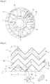
- a degasser using the invention comprises, as shown in the figures 1 And 2 , a movable part 1 rotating around a longitudinal axis of symmetry forms a vein 4 of revolution around the central axis of symmetry X, intended to circulate the mixture of air and oil to be separated.
- the vein 4 has an axial inlet 5 intended for the entry of the mixture of air and oil to be separated.
- This axial inlet 5 corresponds to a first end of a first part 6 of the vein 4 which extends essentially axially, with a view to centrifuging the mixture.
- the first part of vein 6, which extends axially, acts as a centrifugation chamber because it is there that the centrifugal force is exerted with the greatest force on the air/oil mixture. It is therefore called centrifugation enclosure 6 in the remainder of the description.
- the vein 4 here further comprises a plurality of compartments distributed circumferentially around the axis of symmetry X.
- the compartments are formed between longitudinal partitions 7 extending radially.
- these axial partitions 7 connect the first 2 and the second shell 3, thus forming a connection which joins them together.
- Each compartment communicates with the axial inlet 5 of the mixture.
- the centrifugation enclosure 6 is closed axially by a portion 3a of the second shell 3, substantially perpendicular to the axis of symmetry first 2 and the second shell 3.
- the second shell 3 forms a radially external wall 3b of the centrifugation enclosure 6 which is substantially annular, between the inlet 5 and the part 3a of the second shell which axially limits the enclosure of centrifugation 6 at its second end.
- the centrifugation enclosure 6 comprises a plurality of radial oil outlets 8, in the form of through orifices formed in the radially outer wall 3b and is configured to be able to evacuate the oil separated from the mixture by the effect of force centrifugal degasser.
- Each compartment of the vein 4 is connected to one or more radial oil outlet(s) 8.
- the first shell 2 forms a radially internal wall of the compartments of the vein in the centrifugation enclosure 6. It stops axially before the axial portion 3a of the second shell 3, starting from the entrance 5 of the vein, to provide the radial opening 9 towards the inside at the second end of the centrifugation enclosure 6. Its shape can be optimized to promote the separation of the oil and to minimize pressure losses, particularly at the level of the elbow formed at level of the radial outlet.
- the radially internal wall is substantially annular starting from the axial inlet 5 and has an axial end 2a opposite the axial inlet 5 forming a bead or a rounded circumferential plate at the level of the second end of the centrifugation enclosure 6. This shape of the axial end 2a of the first shell tends to return the fluid radially outwards to the passage of the elbow formed in the vein 4 at the outlet of the centrifugation enclosure 6, so as to optimize the flow of the air/oil mixture flow.
- the vein 4 comprises a second part 10 which communicates with the centrifugation enclosure 6 via the radial opening 9 between the first 2 and the second 3 shells and which is configured to guide the fluid towards a radial outlet 11 in an empty cylindrical space , which extends axially between the limits of the centrifugation enclosure 6.
- the first 2 and the second 3 shells form collars 12, 13, which limit said empty cylinder space. These collars 12, 13 are configured to connect the part 1 to a hollow shaft 14, which drives the part in rotation.
- the part 1 is used in a degasser which includes a pinion 15 for rotating the part, itself comprising a web 16.
- the web 16 is integrally connected to the moving part 1 and includes openings opposite the axial inlet 5 for the passage of the mixture into the compartments of the vein 4.
- the web 16 is also integrally connected to the hollow shaft 14.
- part 1 is produced by an additive manufacturing method which makes it possible to produce the complex shapes of the example, in particular with a view to promoting the separation of the oil droplets from the mixture while minimizing pressure losses.
- the additive manufacturing of the assembly can be done, in a known manner, by a controlled laser fusion process of a metal powder.
- the example presented is in no way limiting for the implementation of the invention and manufacturing methods by machining or casting can also be used for more conventional shapes of the passage of the mixture in the moving part. 1.
- the air containing oil therefore enters the moving part 1 through the openings of the veil 16 towards the axial inlet 5 of the compartments of the centrifugation enclosure 6.
- the longitudinal partitions 7 form fins which rotate the mixture entering adjacent compartments.
- the oil present in the mixture forms a mist composed of more or less fine droplets, represented schematically by points on the figures 1 And 2 .
- the droplets are captured, that is to say captured by the axial partitions 7 of the rotating part 1 or stuck to the peripheral wall 3b of the centrifugation enclosure 6. They form an oil film there, which is drained while traveling, under the effect of the centrifugal, along the walls then ejected towards the outside of the degasser through the orifices 8 provided on the peripheral wall 3b.
- the shape of the axial partitions 7 is modified in order to limit this phenomenon.
- the surface of the axial partitions is treated to be rough.
- the asperities linked to the structure are irregular but have an average height slightly greater than the thickness of the oil film 17 forming against the partition 7, typically of the order of a tenth of a millimeter.
- the asperities form obstacles against which the droplets come up against and limit the rebound phenomenon.
- the asperities create crevices protecting the oil film 17 formed by hiding it from the air flow Fi running along the wall. The oil film 17 can then make its way through the crevices to rise radially towards the peripheral wall 3b comprising the outlet orifices 8.
- the number of longitudinal partitions 7b is multiplied, so that the distance between two successive partitions 7b is significantly less, at least by a factor of three, than the radial extension of the centrifugation enclosure 6. If we refer to the example of the figure 8 , this distance is at least ten times less than the radial extension of the partitions 7b.
- the angles ⁇ 1 and ⁇ 2 are not necessarily equal, the chevrons are not necessarily symmetrical as in the figure.
- a partition 7b comprises nine plates 18a to 18i.
- the circumferential distance a between two partitions is less than the axial extension b of the rafters and substantially equal to the circumferential extension of the rafters.
- the air flow F1 loaded with oil droplets therefore follows a sinuous path in the axial direction.
- Radial channels 19 are also formed on either side on the surfaces of the plates 18a to 18i of the axial partitions 7b. As indicated on the figures 6 And 7 , several channels 19 are arranged on the surface of each plate 18a to 18i, between two folds of the longitudinal partition 7b, and these channels extend over the entire radial height of the longitudinal partition 7b.
- Several variants are possible to form channels 19. Box A on the Figure 6 shows a first variant in which the channels are formed between transverse fins on the plates 18a to 18i. Box B on the Figure 6 shows a second variant in which the plates 18a to 18i are thin and have a crenellated profile. The channels are then formed by the slots.
- There Figure 7 suggests another variant where the channels are dug in the thickness of the plates 18a to 18i.
- the width c and the depth d of the channels 19 is adjusted to collect the oil deposited on the partition 7b and to protect the oil film 17 which forms there from the air flow F1 running along the partition.
- the drops of oil represented by dots, are projected towards the partitions by the undulations. They are then captured by the radial channels 19 and, as illustrated in the Figure 7 , they form oil films 17 which flow along said channels towards the outer peripheral wall 3b under the effect of centrifugal force, while being relatively protected from the flow F1.
- the longitudinal partitions 7b start just behind the axial inlet 5 of the centrifugation enclosure 6 and go to the opposite axial end formed by the transverse wall 3a.
- all the longitudinal partitions 7b do not start from the entrance 5 of the enclosure centrifugation 6.
- One or more parts of ripples can be removed.
- the first plate 18a' of the second partition 7b starting from the bottom is removed. This causes the second partition 7b to start at a distance e from the axial inlet 5.
- the widths and depths of the evacuation channels 19 can also vary in the axial direction, as the air advances in the degasser. Their depths can also vary depending on their location.
- FIG. 8 illustrates this embodiment with a tight annular row of longitudinal partitions 7b.
- the oil outlet orifices 8 are here made on the exterior wall 3a in each compartment between two enclosures 7b in locations close to the folding points between two plates 18a, 18b, etc. In fact it is at the level of these fold points that the oil sent towards the peripheral wall 3a will tend to accumulate.
- the invention is not limited to the examples presented. It also covers numerous forms of undulation of longitudinal partitions, as well as partitions whose shapes evolve in the axial and radial directions. Furthermore, all of these solutions can be applied with a rich diversity of materials to form the longitudinal partitions 7b: aluminum, steel, plastic, etc.
- additive manufacturing makes it possible to adapt the partitions 7b to complex shapes of the centrifugation enclosure.
- the peripheral wall 3b also collects centrifuged droplets inside the mixture passing through each compartment.
- all the oil separated from the mixture by the degasser inside the enclosure 6 is collected by said peripheral wall 3b. It is therefore important that this oil is drained effectively towards the orifices 8 provided on the peripheral wall 3b to be ejected towards the outside of the degasser. This prevents a pocket of oil from accumulating against the outer wall 3b, and the risk of oil being torn off by the flow of the mixture and then leaving in the hollow shaft 14 via the radial outlet 11, thus harming the performance of the degasser.
- the radially internal surface of said peripheral wall 3b comprises hollow patterns connected to the mouth of the evacuation orifices 8, so as to drain the oil collected by said peripheral wall 3b towards said orifices 8.
- the internal surface of the peripheral wall 3b forms grooves or longitudinal channels, 17a and 17b, inside each compartment, between two longitudinal walls 7.
- the evacuation orifices 8 are distributed in axial rows at the bottom of each channel , 17a or 17b, along the greatest radial distance line in the channel.
- in each compartment there is a central channel 17a and two side channels 17b, located near the junction with the longitudinal walls 7.
- the arrows of the Figure 10 schematically illustrate the path of oil droplets which, once arriving on the peripheral wall 3b, are guided by centrifugal effect towards the bottom of the channels, 17a or 17b, to be evacuated through the orifices 8.
- the evacuation orifices 8 are also distributed in axial rows along the peripheral wall 3b in each compartment, between two longitudinal walls 7.
- a bowl 18 surrounds each orifice 8 on the internal surface of the peripheral wall 3b.
- Each bowl has the shape of a portion of a sphere hollowed out in the internal surface of the wall 3b.
- FIG 11 shows an exemplary embodiment where the use of cups 18 around the orifices 8 is combined with the previous embodiment.
- the spherical bowls 18 are here dug in the central channel 17a of a peripheral wall 3b previously shaped as on the figures 9 and 10 .
- the arrow present in the Figure 11 illustrates the way in which an oil droplet can be captured towards an orifice 8 by such a wall 3b.
- the internal surface of the peripheral wall 3b can have undulations of variable shape along the circumferential directions ⁇ and axial directions R.
- the surface undulations in the circumferential direction are defined by an angular step ⁇ 1 and an amplitude between a maximum radius R1 and a minimum radius R2.
- the step ⁇ 1 and the amplitudes (R1-R2) can vary from one compartment of the enclosure to another.
- the pitch and the amplitude can also vary circumferentially and/or axially inside a compartment, to take into account the way in which the oil arrives on the wall 3b.
- the surface undulations in the axial direction are defined by a longitudinal pitch L1 and an amplitude between a maximum radius R'1 and a minimum radius R'2.
- the pitch and amplitudes of the example of the Figure 13 can vary in the axial direction.
- the pitch and the amplitude can also vary circumferentially and/or axially inside a compartment, to take into account the way in which the oil arrives on the wall 3b.
- the orifices 8 are preferably located at locations of maximum radius on the surface.
- the maximum radius zones, 19 or 20, presented on the figures 12 and 13 can form longitudinal or transverse channels, or bowls by combining the undulations in the axial direction and the circumferential direction.
- the undulations can have substantially sinusoidal shapes as in the figures. For example, if the orifices 8 are distributed periodically on longitudinal lines, as in the case of figures 10 and 11 , we can combine circumferential undulations aligned with the position of the longitudinal lines and longitudinal undulations aligned with the longitudinal position of the orifices to form bowls centered on the orifices.
- peripheral wall 3b aluminum, steel, plastic, etc.
- additive manufacturing makes it possible to easily obtain complex shapes of the centrifugation chamber and in particular for the internal surface of the peripheral wall 3b.
Landscapes
- Engineering & Computer Science (AREA)
- Mechanical Engineering (AREA)
- General Engineering & Computer Science (AREA)
- Chemical & Material Sciences (AREA)
- Chemical Kinetics & Catalysis (AREA)
- Centrifugal Separators (AREA)
- Lubrication Details And Ventilation Of Internal Combustion Engines (AREA)
- Separating Particles In Gases By Inertia (AREA)
- Structures Of Non-Positive Displacement Pumps (AREA)
Claims (10)
- Bauteil (1) für einen zentrifugalen Entgaser eines Luft-Öl-Gemischs einer Turbomaschine, das dazu vorgesehen ist, sich um eine Symmetrieachse (X) zu drehen, das ein ringförmiges Gehäuse (6) zur zentrifugalen Abscheidung des Gemischs bildet, wobei das Gehäuse (6) eine Fluiddurchgangsader bildet, bei der ein Eingang (5) zur Versorgung des Gehäuses (6) mit dem Gemisch axial ausgerichtet ist und bei der ein erster Ausgang (11) für das Austreten der entölen Luft, die von dem Gemisch abgeschieden ist, radial nach innen ausgerichtet ist, wobei das Gehäuse (6) weiter mindestens einen zweiten Ölausgang (8) umfasst, der radial nach außen ausgerichtet ist und dazu vorgesehen ist, das von dem Gemisch abgeschiedene Öl zur Außenseite des Entgasers abzuführen, dadurch gekennzeichnet, dass das Gehäuse (6) zwei Längswände (7) umfasst, die dieses radial durchqueren, wobei mindestens eine der Oberflächen der Längswände (7) Oberflächenstrukturen und/oder Wellen aufweist, die eingerichtet sind, um Hindernisse für einen Fluss (F1) des Gemischs zu bilden, die entlang der Oberfläche der Längswände verlaufen.
- Bauteil (1) nach Anspruch 1, dadurch gekennzeichnet, dass es eine ringförmige Reihe der Längswände (7b) umfasst, die zwischen zwei aufeinanderfolgenden Längswänden Flussdurchgänge (F1) durch das Gehäuse (6) in der axialen Richtung bilden, wobei der Abstand zwischen den Längswänden (7b) kleiner als ihre radiale Erstreckung ist.
- Bauteil (1) nach einem der Ansprüche 1 und 2, dadurch gekennzeichnet, dass die Oberfläche der Längswände (7) einen rauen Oberflächenzustand aufweist, um einen Ölfilm des Flusses (F1) des Gemischs zu schützen.
- Bauteil (1) nach einem der vorstehenden Ansprüche, dadurch gekennzeichnet, dass die Längswände (7b) dünne Platten bilden, die Wellen in der axialen Richtung aufweisen.
- Bauteil (1) nach einem der vorstehenden Ansprüche, dadurch gekennzeichnet, dass sich ausgehöhlte Kanäle (19) über mindestens eine der Flächen der Längswände (7b) radial über diese erstrecken, um einen Ölfilm zu einer äußeren Umfangswand (3b) des Zentrifugierungsgehäuses (6) abzuleiten
- Bauteil (1) nach den Ansprüchen 4 und 5, dadurch gekennzeichnet, dass mehrere Kanäle (19) zwischen zwei Faltungen einer Welle angeordnet sind.
- Bauteil (1) nach einem der Ansprüche 5 oder 6 in Abhängigkeit von Anspruch 4, dadurch gekennzeichnet, dass der zweite Ölausgang (8) Öffnungen umfasst, die eine äußere Umfangswand (3b) des Zentrifugierungsgehäuses (6) durchqueren, die in jedem Fach zwischen zwei Längswänden (7b) an den Faltungen zwischen zwei Wellen positioniert sind.
- Bauteil (1) nach einem der vorstehenden Ansprüche, in Abhängigkeit von Anspruch 2, dadurch gekennzeichnet, dass gewisse Längswände nach den anderen in der axialen Richtung hinter dem axialen Eingang (5) beginnen.
- Bauteil (1) nach einem der vorstehenden Ansprüche, dadurch gekennzeichnet, dass es einstückig gefertigt ist, zum Beispiel durch additive Fertigung.
- Zentrifugaler Entgaser eines Luft-Öl-Gemischs einer Turbomaschine, umfassend ein Bauteil (1) nach einem der vorstehenden Ansprüche, eine Hohlwelle (14), die fest mit dem Bauteil verbunden ist und dazu konfiguriert ist, die aus dem inneren radialen Ausgang (11) austretende Luft zu sammeln, und ein Ritzel (15), um die Anordnung in Drehung zu versetzen.
Applications Claiming Priority (2)
| Application Number | Priority Date | Filing Date | Title |
|---|---|---|---|
| FR1905487A FR3096275B1 (fr) | 2019-05-24 | 2019-05-24 | Pièce pour dégazeur centrifuge de turbomachine avec parois longitudinales adaptées |
| PCT/FR2020/050836 WO2020240116A1 (fr) | 2019-05-24 | 2020-05-20 | Piece pour degazeur centrifuge de turbomachine avec parois longitudinales adaptees |
Publications (2)
| Publication Number | Publication Date |
|---|---|
| EP3976937A1 EP3976937A1 (de) | 2022-04-06 |
| EP3976937B1 true EP3976937B1 (de) | 2023-11-29 |
Family
ID=67999844
Family Applications (1)
| Application Number | Title | Priority Date | Filing Date |
|---|---|---|---|
| EP20737254.1A Active EP3976937B1 (de) | 2019-05-24 | 2020-05-20 | Teil für einen turbomaschinenzentrifugalentgaser mit angepassten longitudinalen wänden |
Country Status (6)
| Country | Link |
|---|---|
| US (1) | US11925888B2 (de) |
| EP (1) | EP3976937B1 (de) |
| CN (1) | CN114007720B (de) |
| FR (1) | FR3096275B1 (de) |
| PL (1) | PL3976937T3 (de) |
| WO (1) | WO2020240116A1 (de) |
Family Cites Families (36)
| Publication number | Priority date | Publication date | Assignee | Title |
|---|---|---|---|---|
| FR1590886A (de) * | 1968-11-06 | 1970-04-20 | ||
| US3630379A (en) * | 1970-08-07 | 1971-12-28 | Pennwalt Corp | Step ring centrifuge screen |
| GB1508212A (en) * | 1975-02-10 | 1978-04-19 | Rolls Royce | Apparatus for separating suspension of liquids in gas |
| US5114446A (en) * | 1991-02-15 | 1992-05-19 | United Technologies Corporation | Deoiler for jet engine |
| FR2742804B1 (fr) * | 1995-12-20 | 1998-01-16 | Snecma | Rotor deshuileur pour enceinte de lubrification |
| US5716423A (en) * | 1995-12-21 | 1998-02-10 | United Technologies Corporation | Multi-stage deoiler with porous media |
| US6033450A (en) * | 1995-12-21 | 2000-03-07 | United Technologies Corporation | Deoiler shaft vortex separator |
| US6398833B1 (en) * | 2000-11-06 | 2002-06-04 | Pratt & Whitney Canada Corp. | Air/oil separator |
| DE10148000A1 (de) * | 2001-09-28 | 2003-04-10 | Rolls Royce Deutschland | Ölseparator |
| GB0206243D0 (en) * | 2002-03-16 | 2002-05-01 | Rolls Royce Plc | An air/oil separator |
| US7063734B2 (en) * | 2004-03-23 | 2006-06-20 | Pratt & Whitney Canada Corp. | Air/oil separation system and method |
| CA2569784C (fr) * | 2004-07-08 | 2010-08-31 | Luigi Pietro Della Casa | Separateur centrifuge pour melanges a milieu liquide ou gazeux |
| EP1930059B1 (de) * | 2006-11-13 | 2013-05-15 | Sulzer Chemtech AG | Tropfenabscheider |
| FR2937680B1 (fr) * | 2008-10-24 | 2013-11-08 | Snecma | Rotor deshuileur pour turbomachine |
| FR2947857B1 (fr) | 2009-07-10 | 2012-03-30 | Snecma | Agencement de deshuileur |
| US9689263B2 (en) * | 2009-10-27 | 2017-06-27 | General Electric Company | Droplet catcher for centrifugal compressor |
| US8657931B2 (en) * | 2011-08-17 | 2014-02-25 | Hamilton Sundstrand Corporation | Gearbox deoiler with sychnronizer |
| US9028576B2 (en) * | 2011-11-09 | 2015-05-12 | Hamilton Sundstrand Corporation | Gearbox deoiler with pre-pressuring component |
| EP2664386B1 (de) * | 2012-05-18 | 2015-06-24 | Alfa Laval Corporate AB | Zentrifugalabscheider |
| US8945284B2 (en) * | 2012-06-05 | 2015-02-03 | Hamilton Sundstrand Corporation | Deoiler seal |
| ITBO20120716A1 (it) * | 2012-12-31 | 2014-07-01 | Avio Spa | Filtro provvisto di elementi strutturali, in particolare per un separatore a rotazione |
| FR3007463B1 (fr) * | 2013-06-21 | 2017-10-20 | Hispano-Suiza | Boitier d'accessoires de turbomachine equipe d'un separateur air/huile |
| DE102013114638A1 (de) * | 2013-12-20 | 2015-06-25 | Rolls-Royce Deutschland Ltd & Co Kg | Vorrichtung eines Strahltriebwerks mit wenigstens einem in einem Gehäuse angeordneten und gegenüber dem Gehäuse drehbar ausgeführten Bauteil |
| JP6336037B2 (ja) * | 2014-02-25 | 2018-06-06 | 東京濾器株式会社 | オイルセパレータ |
| US9765644B2 (en) * | 2015-01-20 | 2017-09-19 | United Technologies Corporation | Deoiler debris baffle |
| DE112015006228T5 (de) * | 2015-03-30 | 2017-11-09 | Cummins Filtration Ip, Inc. | Mehrstufige rotierende Tropfenabscheidervorrichtungen |
| CN107614841B (zh) * | 2015-06-09 | 2020-02-21 | 康明斯过滤Ip公司 | 使用低摩擦旋转聚结器接触密封的系统和方法 |
| FR3064304B1 (fr) * | 2017-03-21 | 2019-03-22 | Safran Helicopter Engines | Degazeur centrifuge de turbomachine |
| FR3064305B1 (fr) * | 2017-03-21 | 2019-03-22 | Safran Helicopter Engines | Degazeur centrifuge de turbomachine |
| FR3071418B1 (fr) * | 2017-09-26 | 2019-09-13 | Safran Helicopter Engines | Piece pour degazeur centrifuge de turbomachine et procede de fabrication de ladite piece |
| US10918989B2 (en) * | 2018-04-10 | 2021-02-16 | Pratt & Whitney Canada Corp. | Air-oil separator with two flow paths |
| US10870079B2 (en) * | 2018-04-10 | 2020-12-22 | Pratt & Whitney Canada Corp. | Air-oil separator with first separator radially outward of matrix separator |
| FR3081513B1 (fr) * | 2018-05-28 | 2021-06-18 | Safran Aircraft Engines | Systeme de transmission de puissance comprenant un dispositif de recuperation d'huile de lubrification et turbomachine equipee d'un tel systeme de transmission de puissance |
| FR3083570B1 (fr) * | 2018-07-05 | 2021-09-10 | Safran Helicopter Engines | Degazeur centrifuge monobloc |
| CN112469889B (zh) * | 2018-07-05 | 2022-12-13 | 赛峰集团 | 用于涡轮机离心式通气器的具有过滤网的部件 |
| FR3094756B1 (fr) * | 2019-04-04 | 2021-03-05 | Safran Aircraft Engines | Pignon d’entrainement d’un separateur air/huile d’un boitier d’accessoires de turbomachine |
-
2019
- 2019-05-24 FR FR1905487A patent/FR3096275B1/fr active Active
-
2020
- 2020-05-20 CN CN202080043090.6A patent/CN114007720B/zh active Active
- 2020-05-20 EP EP20737254.1A patent/EP3976937B1/de active Active
- 2020-05-20 PL PL20737254.1T patent/PL3976937T3/pl unknown
- 2020-05-20 US US17/612,804 patent/US11925888B2/en active Active
- 2020-05-20 WO PCT/FR2020/050836 patent/WO2020240116A1/fr unknown
Also Published As
| Publication number | Publication date |
|---|---|
| CN114007720B (zh) | 2023-07-07 |
| EP3976937A1 (de) | 2022-04-06 |
| FR3096275B1 (fr) | 2021-06-18 |
| PL3976937T3 (pl) | 2024-04-08 |
| US20220249995A1 (en) | 2022-08-11 |
| CN114007720A (zh) | 2022-02-01 |
| FR3096275A1 (fr) | 2020-11-27 |
| WO2020240116A1 (fr) | 2020-12-03 |
| US11925888B2 (en) | 2024-03-12 |
Similar Documents
| Publication | Publication Date | Title |
|---|---|---|
| EP3687657B1 (de) | Bauteil für eine zentrifugale trennvorrichtung eines motors und verfahren zu seiner herstellung | |
| EP3818257B1 (de) | Integrierter zentrifugalentgaser | |
| CA2946958C (fr) | Module de turbomachine comportant un carter autour d'un equipement avec un capot de recuperation d'huile de lubrification | |
| EP2553221B1 (de) | Dichtungsvorrichtung für eine Ölkammer eines Düsentriebwerks | |
| FR2933626A1 (fr) | Dispositif avec rotor a media coalesceur pour separer l'huile des gaz de carter d'un moteur a combustion interne. | |
| CA3012406A1 (fr) | Rouet de distribution d'huile avec partitionnement axial et reducteur a train epicycloidal equipe d'un tel rouet | |
| EP3601767A1 (de) | Zentrifugalentlüfter für eine strömungsmaschine | |
| EP3601768B1 (de) | Zentrifugalentlüfter für eine turbomaschine | |
| EP3212898B1 (de) | Schmierölsammelkappe für turbomaschinenausrüstungen | |
| EP3818258B1 (de) | Teil für zentrifugalentlüfter einer turbomaschine mit einem filtergitter | |
| EP0154098B1 (de) | Vorrichtung zur Gas-Flüssig-Trennung und ihre Anwendung bei der Entölung der Abluft aus den Lagergehäusen einer Turbomaschine | |
| EP3976937B1 (de) | Teil für einen turbomaschinenzentrifugalentgaser mit angepassten longitudinalen wänden | |
| EP3131656B1 (de) | Filtrierung eines stroms aus gas/partikeln | |
| FR3075867A1 (fr) | Dispositif de deshuilage d'une enceinte de lubrification de turbomachine | |
| EP4058689B1 (de) | Laufrad für einen planetenträger eines getriebes mit epizykloidengetriebe einer turbomaschine | |
| FR3096276A1 (fr) | Pièce pour dégazeur centrifuge de turbomachine avec parois périphériques adaptées | |
| EP3601754B1 (de) | Drehvorrichtung zur trennung von öl aus dem kurbelgehäusegas einer brennkraftmaschine | |
| FR3096402A1 (fr) | Pièce pour dégazeur centrifuge de turbomachine avec treillis de filtrage | |
| EP3189211B2 (de) | Turbomaschinenwelle |
Legal Events
| Date | Code | Title | Description |
|---|---|---|---|
| STAA | Information on the status of an ep patent application or granted ep patent |
Free format text: STATUS: UNKNOWN |
|
| STAA | Information on the status of an ep patent application or granted ep patent |
Free format text: STATUS: THE INTERNATIONAL PUBLICATION HAS BEEN MADE |
|
| STAA | Information on the status of an ep patent application or granted ep patent |
Free format text: STATUS: THE INTERNATIONAL PUBLICATION HAS BEEN MADE |
|
| PUAI | Public reference made under article 153(3) epc to a published international application that has entered the european phase |
Free format text: ORIGINAL CODE: 0009012 |
|
| STAA | Information on the status of an ep patent application or granted ep patent |
Free format text: STATUS: REQUEST FOR EXAMINATION WAS MADE |
|
| 17P | Request for examination filed |
Effective date: 20211221 |
|
| AK | Designated contracting states |
Kind code of ref document: A1 Designated state(s): AL AT BE BG CH CY CZ DE DK EE ES FI FR GB GR HR HU IE IS IT LI LT LU LV MC MK MT NL NO PL PT RO RS SE SI SK SM TR |
|
| DAV | Request for validation of the european patent (deleted) | ||
| DAX | Request for extension of the european patent (deleted) | ||
| GRAP | Despatch of communication of intention to grant a patent |
Free format text: ORIGINAL CODE: EPIDOSNIGR1 |
|
| STAA | Information on the status of an ep patent application or granted ep patent |
Free format text: STATUS: GRANT OF PATENT IS INTENDED |
|
| INTG | Intention to grant announced |
Effective date: 20230124 |
|
| GRAS | Grant fee paid |
Free format text: ORIGINAL CODE: EPIDOSNIGR3 |
|
| GRAJ | Information related to disapproval of communication of intention to grant by the applicant or resumption of examination proceedings by the epo deleted |
Free format text: ORIGINAL CODE: EPIDOSDIGR1 |
|
| GRAL | Information related to payment of fee for publishing/printing deleted |
Free format text: ORIGINAL CODE: EPIDOSDIGR3 |
|
| STAA | Information on the status of an ep patent application or granted ep patent |
Free format text: STATUS: REQUEST FOR EXAMINATION WAS MADE |
|
| GRAP | Despatch of communication of intention to grant a patent |
Free format text: ORIGINAL CODE: EPIDOSNIGR1 |
|
| STAA | Information on the status of an ep patent application or granted ep patent |
Free format text: STATUS: GRANT OF PATENT IS INTENDED |
|
| INTC | Intention to grant announced (deleted) | ||
| INTG | Intention to grant announced |
Effective date: 20230623 |
|
| GRAA | (expected) grant |
Free format text: ORIGINAL CODE: 0009210 |
|
| STAA | Information on the status of an ep patent application or granted ep patent |
Free format text: STATUS: THE PATENT HAS BEEN GRANTED |
|
| AK | Designated contracting states |
Kind code of ref document: B1 Designated state(s): AL AT BE BG CH CY CZ DE DK EE ES FI FR GB GR HR HU IE IS IT LI LT LU LV MC MK MT NL NO PL PT RO RS SE SI SK SM TR |
|
| REG | Reference to a national code |
Ref country code: GB Ref legal event code: FG4D Free format text: NOT ENGLISH |
|
| REG | Reference to a national code |
Ref country code: CH Ref legal event code: EP |
|
| REG | Reference to a national code |
Ref country code: DE Ref legal event code: R096 Ref document number: 602020021912 Country of ref document: DE |
|
| REG | Reference to a national code |
Ref country code: IE Ref legal event code: FG4D Free format text: LANGUAGE OF EP DOCUMENT: FRENCH |
|
| REG | Reference to a national code |
Ref country code: LT Ref legal event code: MG9D |
|
| REG | Reference to a national code |
Ref country code: NL Ref legal event code: MP Effective date: 20231129 |
|
| PG25 | Lapsed in a contracting state [announced via postgrant information from national office to epo] |
Ref country code: GR Free format text: LAPSE BECAUSE OF FAILURE TO SUBMIT A TRANSLATION OF THE DESCRIPTION OR TO PAY THE FEE WITHIN THE PRESCRIBED TIME-LIMIT Effective date: 20240301 |
|
| PG25 | Lapsed in a contracting state [announced via postgrant information from national office to epo] |
Ref country code: IS Free format text: LAPSE BECAUSE OF FAILURE TO SUBMIT A TRANSLATION OF THE DESCRIPTION OR TO PAY THE FEE WITHIN THE PRESCRIBED TIME-LIMIT Effective date: 20240329 |
|
| PG25 | Lapsed in a contracting state [announced via postgrant information from national office to epo] |
Ref country code: LT Free format text: LAPSE BECAUSE OF FAILURE TO SUBMIT A TRANSLATION OF THE DESCRIPTION OR TO PAY THE FEE WITHIN THE PRESCRIBED TIME-LIMIT Effective date: 20231129 |
|
| PG25 | Lapsed in a contracting state [announced via postgrant information from national office to epo] |
Ref country code: ES Free format text: LAPSE BECAUSE OF FAILURE TO SUBMIT A TRANSLATION OF THE DESCRIPTION OR TO PAY THE FEE WITHIN THE PRESCRIBED TIME-LIMIT Effective date: 20231129 |
|
| PG25 | Lapsed in a contracting state [announced via postgrant information from national office to epo] |
Ref country code: LT Free format text: LAPSE BECAUSE OF FAILURE TO SUBMIT A TRANSLATION OF THE DESCRIPTION OR TO PAY THE FEE WITHIN THE PRESCRIBED TIME-LIMIT Effective date: 20231129 Ref country code: IS Free format text: LAPSE BECAUSE OF FAILURE TO SUBMIT A TRANSLATION OF THE DESCRIPTION OR TO PAY THE FEE WITHIN THE PRESCRIBED TIME-LIMIT Effective date: 20240329 Ref country code: GR Free format text: LAPSE BECAUSE OF FAILURE TO SUBMIT A TRANSLATION OF THE DESCRIPTION OR TO PAY THE FEE WITHIN THE PRESCRIBED TIME-LIMIT Effective date: 20240301 Ref country code: ES Free format text: LAPSE BECAUSE OF FAILURE TO SUBMIT A TRANSLATION OF THE DESCRIPTION OR TO PAY THE FEE WITHIN THE PRESCRIBED TIME-LIMIT Effective date: 20231129 Ref country code: BG Free format text: LAPSE BECAUSE OF FAILURE TO SUBMIT A TRANSLATION OF THE DESCRIPTION OR TO PAY THE FEE WITHIN THE PRESCRIBED TIME-LIMIT Effective date: 20240229 |
|
| REG | Reference to a national code |
Ref country code: AT Ref legal event code: MK05 Ref document number: 1636322 Country of ref document: AT Kind code of ref document: T Effective date: 20231129 |
|
| PG25 | Lapsed in a contracting state [announced via postgrant information from national office to epo] |
Ref country code: NL Free format text: LAPSE BECAUSE OF FAILURE TO SUBMIT A TRANSLATION OF THE DESCRIPTION OR TO PAY THE FEE WITHIN THE PRESCRIBED TIME-LIMIT Effective date: 20231129 |