EP3976933B1 - Hitzeschild für einen gasturbinenmotor - Google Patents
Hitzeschild für einen gasturbinenmotor Download PDFInfo
- Publication number
- EP3976933B1 EP3976933B1 EP20732110.0A EP20732110A EP3976933B1 EP 3976933 B1 EP3976933 B1 EP 3976933B1 EP 20732110 A EP20732110 A EP 20732110A EP 3976933 B1 EP3976933 B1 EP 3976933B1
- Authority
- EP
- European Patent Office
- Prior art keywords
- heatshield
- arm
- stiffening structure
- hook
- arms
- Prior art date
- Legal status (The legal status is an assumption and is not a legal conclusion. Google has not performed a legal analysis and makes no representation as to the accuracy of the status listed.)
- Active
Links
Images



Classifications
-
- F—MECHANICAL ENGINEERING; LIGHTING; HEATING; WEAPONS; BLASTING
- F01—MACHINES OR ENGINES IN GENERAL; ENGINE PLANTS IN GENERAL; STEAM ENGINES
- F01D—NON-POSITIVE DISPLACEMENT MACHINES OR ENGINES, e.g. STEAM TURBINES
- F01D25/00—Component parts, details, or accessories, not provided for in, or of interest apart from, other groups
- F01D25/08—Cooling; Heating; Heat-insulation
- F01D25/14—Casings modified therefor
- F01D25/145—Thermally insulated casings
-
- F—MECHANICAL ENGINEERING; LIGHTING; HEATING; WEAPONS; BLASTING
- F01—MACHINES OR ENGINES IN GENERAL; ENGINE PLANTS IN GENERAL; STEAM ENGINES
- F01D—NON-POSITIVE DISPLACEMENT MACHINES OR ENGINES, e.g. STEAM TURBINES
- F01D25/00—Component parts, details, or accessories, not provided for in, or of interest apart from, other groups
- F01D25/24—Casings; Casing parts, e.g. diaphragms, casing fastenings
- F01D25/246—Fastening of diaphragms or stator-rings
-
- F—MECHANICAL ENGINEERING; LIGHTING; HEATING; WEAPONS; BLASTING
- F01—MACHINES OR ENGINES IN GENERAL; ENGINE PLANTS IN GENERAL; STEAM ENGINES
- F01D—NON-POSITIVE DISPLACEMENT MACHINES OR ENGINES, e.g. STEAM TURBINES
- F01D9/00—Stators
- F01D9/02—Nozzles; Nozzle boxes; Stator blades; Guide conduits, e.g. individual nozzles
- F01D9/04—Nozzles; Nozzle boxes; Stator blades; Guide conduits, e.g. individual nozzles forming ring or sector
-
- F—MECHANICAL ENGINEERING; LIGHTING; HEATING; WEAPONS; BLASTING
- F01—MACHINES OR ENGINES IN GENERAL; ENGINE PLANTS IN GENERAL; STEAM ENGINES
- F01D—NON-POSITIVE DISPLACEMENT MACHINES OR ENGINES, e.g. STEAM TURBINES
- F01D11/00—Preventing or minimising internal leakage of working-fluid, e.g. between stages
- F01D11/005—Sealing means between non relatively rotating elements
-
- F—MECHANICAL ENGINEERING; LIGHTING; HEATING; WEAPONS; BLASTING
- F01—MACHINES OR ENGINES IN GENERAL; ENGINE PLANTS IN GENERAL; STEAM ENGINES
- F01D—NON-POSITIVE DISPLACEMENT MACHINES OR ENGINES, e.g. STEAM TURBINES
- F01D11/00—Preventing or minimising internal leakage of working-fluid, e.g. between stages
- F01D11/08—Preventing or minimising internal leakage of working-fluid, e.g. between stages for sealing space between rotor blade tips and stator
- F01D11/14—Adjusting or regulating tip-clearance, i.e. distance between rotor-blade tips and stator casing
- F01D11/20—Actively adjusting tip-clearance
- F01D11/24—Actively adjusting tip-clearance by selectively cooling-heating stator or rotor components
-
- F—MECHANICAL ENGINEERING; LIGHTING; HEATING; WEAPONS; BLASTING
- F01—MACHINES OR ENGINES IN GENERAL; ENGINE PLANTS IN GENERAL; STEAM ENGINES
- F01D—NON-POSITIVE DISPLACEMENT MACHINES OR ENGINES, e.g. STEAM TURBINES
- F01D25/00—Component parts, details, or accessories, not provided for in, or of interest apart from, other groups
- F01D25/08—Cooling; Heating; Heat-insulation
- F01D25/12—Cooling
-
- F—MECHANICAL ENGINEERING; LIGHTING; HEATING; WEAPONS; BLASTING
- F01—MACHINES OR ENGINES IN GENERAL; ENGINE PLANTS IN GENERAL; STEAM ENGINES
- F01D—NON-POSITIVE DISPLACEMENT MACHINES OR ENGINES, e.g. STEAM TURBINES
- F01D25/00—Component parts, details, or accessories, not provided for in, or of interest apart from, other groups
- F01D25/08—Cooling; Heating; Heat-insulation
- F01D25/14—Casings modified therefor
-
- F—MECHANICAL ENGINEERING; LIGHTING; HEATING; WEAPONS; BLASTING
- F02—COMBUSTION ENGINES; HOT-GAS OR COMBUSTION-PRODUCT ENGINE PLANTS
- F02C—GAS-TURBINE PLANTS; AIR INTAKES FOR JET-PROPULSION PLANTS; CONTROLLING FUEL SUPPLY IN AIR-BREATHING JET-PROPULSION PLANTS
- F02C7/00—Features, components parts, details or accessories, not provided for in, or of interest apart form groups F02C1/00 - F02C6/00; Air intakes for jet-propulsion plants
- F02C7/24—Heat or noise insulation
-
- F—MECHANICAL ENGINEERING; LIGHTING; HEATING; WEAPONS; BLASTING
- F05—INDEXING SCHEMES RELATING TO ENGINES OR PUMPS IN VARIOUS SUBCLASSES OF CLASSES F01-F04
- F05D—INDEXING SCHEME FOR ASPECTS RELATING TO NON-POSITIVE-DISPLACEMENT MACHINES OR ENGINES, GAS-TURBINES OR JET-PROPULSION PLANTS
- F05D2240/00—Components
- F05D2240/10—Stators
- F05D2240/11—Shroud seal segments
-
- F—MECHANICAL ENGINEERING; LIGHTING; HEATING; WEAPONS; BLASTING
- F05—INDEXING SCHEMES RELATING TO ENGINES OR PUMPS IN VARIOUS SUBCLASSES OF CLASSES F01-F04
- F05D—INDEXING SCHEME FOR ASPECTS RELATING TO NON-POSITIVE-DISPLACEMENT MACHINES OR ENGINES, GAS-TURBINES OR JET-PROPULSION PLANTS
- F05D2240/00—Components
- F05D2240/10—Stators
- F05D2240/15—Heat shield
-
- F—MECHANICAL ENGINEERING; LIGHTING; HEATING; WEAPONS; BLASTING
- F05—INDEXING SCHEMES RELATING TO ENGINES OR PUMPS IN VARIOUS SUBCLASSES OF CLASSES F01-F04
- F05D—INDEXING SCHEME FOR ASPECTS RELATING TO NON-POSITIVE-DISPLACEMENT MACHINES OR ENGINES, GAS-TURBINES OR JET-PROPULSION PLANTS
- F05D2240/00—Components
- F05D2240/80—Platforms for stationary or moving blades
- F05D2240/81—Cooled platforms
-
- F—MECHANICAL ENGINEERING; LIGHTING; HEATING; WEAPONS; BLASTING
- F05—INDEXING SCHEMES RELATING TO ENGINES OR PUMPS IN VARIOUS SUBCLASSES OF CLASSES F01-F04
- F05D—INDEXING SCHEME FOR ASPECTS RELATING TO NON-POSITIVE-DISPLACEMENT MACHINES OR ENGINES, GAS-TURBINES OR JET-PROPULSION PLANTS
- F05D2260/00—Function
- F05D2260/20—Heat transfer, e.g. cooling
- F05D2260/201—Heat transfer, e.g. cooling by impingement of a fluid
-
- F—MECHANICAL ENGINEERING; LIGHTING; HEATING; WEAPONS; BLASTING
- F05—INDEXING SCHEMES RELATING TO ENGINES OR PUMPS IN VARIOUS SUBCLASSES OF CLASSES F01-F04
- F05D—INDEXING SCHEME FOR ASPECTS RELATING TO NON-POSITIVE-DISPLACEMENT MACHINES OR ENGINES, GAS-TURBINES OR JET-PROPULSION PLANTS
- F05D2260/00—Function
- F05D2260/20—Heat transfer, e.g. cooling
- F05D2260/231—Preventing heat transfer
-
- F—MECHANICAL ENGINEERING; LIGHTING; HEATING; WEAPONS; BLASTING
- F05—INDEXING SCHEMES RELATING TO ENGINES OR PUMPS IN VARIOUS SUBCLASSES OF CLASSES F01-F04
- F05D—INDEXING SCHEME FOR ASPECTS RELATING TO NON-POSITIVE-DISPLACEMENT MACHINES OR ENGINES, GAS-TURBINES OR JET-PROPULSION PLANTS
- F05D2260/00—Function
- F05D2260/30—Retaining components in desired mutual position
-
- F—MECHANICAL ENGINEERING; LIGHTING; HEATING; WEAPONS; BLASTING
- F05—INDEXING SCHEMES RELATING TO ENGINES OR PUMPS IN VARIOUS SUBCLASSES OF CLASSES F01-F04
- F05D—INDEXING SCHEME FOR ASPECTS RELATING TO NON-POSITIVE-DISPLACEMENT MACHINES OR ENGINES, GAS-TURBINES OR JET-PROPULSION PLANTS
- F05D2260/00—Function
- F05D2260/94—Functionality given by mechanical stress related aspects such as low cycle fatigue [LCF] of high cycle fatigue [HCF]
- F05D2260/941—Functionality given by mechanical stress related aspects such as low cycle fatigue [LCF] of high cycle fatigue [HCF] particularly aimed at mechanical or thermal stress reduction
-
- Y—GENERAL TAGGING OF NEW TECHNOLOGICAL DEVELOPMENTS; GENERAL TAGGING OF CROSS-SECTIONAL TECHNOLOGIES SPANNING OVER SEVERAL SECTIONS OF THE IPC; TECHNICAL SUBJECTS COVERED BY FORMER USPC CROSS-REFERENCE ART COLLECTIONS [XRACs] AND DIGESTS
- Y02—TECHNOLOGIES OR APPLICATIONS FOR MITIGATION OR ADAPTATION AGAINST CLIMATE CHANGE
- Y02T—CLIMATE CHANGE MITIGATION TECHNOLOGIES RELATED TO TRANSPORTATION
- Y02T50/00—Aeronautics or air transport
- Y02T50/60—Efficient propulsion technologies, e.g. for aircraft
Definitions
- the present invention relates to a heatshield that may be used in a gas turbine engine and in particular a stiffening and flow-control feature to improve longevity of the heatshield.
- a heatshield can be found in several locations in a gas turbine engine and in particular the heatshield can be located radially outwardly of an annular array of turbine blades.
- the heatshield is usually a circumferential segment of an array of heatshields which are held in position by a carrier structure.
- the heatshield forms part of a gas-path which channels combustion gases through the turbine and drives turbine rotor blades in a conventional manner.
- These heatshields have a hot side, which is exposed to the hot working gases of the turbine, and a cold side facing radially outwardly, and which is often cooled with cooling air. It is important that there is a minimal gap between the tip of the blade and the heatshield to minimise over tip leakage and therefore minimise efficiency losses.
- long ribs are provided on the cold side to stiffen the heatshield.
- the long ribs are integral or unitary with the cold side and form cooling channels.
- An impingement plate is brazed on the cold side and covers the long ribs. Cooling air is distributed along the cooling channels.
- the heatshield requires even distribution of the cooling air across the inlets of the heatshield cooling holes. Special design features are usually needed to achieve that, because cooling air supply from the carrier is typically very localized. Such cooling localisation can also incur localised thermal gradients.
- a vane cluster includes a split damped outer shroud and an inner shroud spaced from the split damped outer shroud with a multiple of stator vane airfoils that extend between the split damped outer shroud and the inner shroud.
- EP 1 965 032 A2 discloses a turbine engine blade outer air seal segment that has a body having a base portion.
- the base portion has a transversely concave ID face, a forward end, an aft end, and first and second circumferential edges.
- the body has at least one mounting hook.
- At least one cover plate is secured to the body to define at least one cavity.
- the cover plate has a plurality of feed holes.
- a plurality of outlet holes extend through the base portion to the ID face.
- At least one of the base portion and cover plate comprises a protruding portion protruding into the cavity to form a partial restriction separating circumferentially and fore-aft offset cavity portions.
- a heatshield for a gas turbine engine comprising a main body having a leading edge, a trailing edge, lateral edges, a first surface and a second surface, the first surface being exposed to a hot working gas in use passing through the gas turbine engine, a leading hook and a trailing hook each extending between the lateral edges, the leading hook and the trailing hook extending from the second surface, characterised by a stiffening structure extending from the leading hook to the trailing hook and free from direct contact or attachment to the second surface.
- the stiffening structure being monolithic with the leading hook and the trailing hook.
- the stiffening structure may be arranged in the general form of at least one X when looking towards the second surface.
- the stiffening structure may comprise four arms. Two arms may attach to the leading hook. Two arms may attach to the trailing hook. The fours arms may meet at an intersection.
- the stiffening structure may comprise an extended portion.
- the extended portion may extend between any one or more of the pairs of arms, arm 104A and arm 104B, arm 104B and arm 104C, arm 104C and arm 104D and arm 104A and arm 104D.
- the extended portion may block the jet of coolant from impinging on second surface and/or at least one inlet defined in the second surface.
- the heatshield may comprise a centre-line and perpendicular to the centre-line a line.
- An angle ⁇ is defined from an arm 104C to the line and an angle ⁇ is defined from the arm 104C to another arm 104D, both arms 104C, 104D attached to the same leading or trailing hook.
- the ratio of angles may be angle ⁇ / angle ⁇ ⁇ 2.
- the stiffening structure may comprise one or more of the cross-sectional profiles: an I-beam, a T-beam, a box-beam or a rectangle.
- the stiffening structure may be a beam arrangement.
- the beam arrangement comprising at least one beam, the at least one beam having at least one web and at least one flange.
- the extended portion may be formed by an extension of the flange, preferably the radially outer flange.
- the stiffening structure may be a lattice structure.
- the lattice structure may be an array of X-shaped elements, each X-shaped element having the arms.
- the extended portion may not be connected to either of the leading hook or the trailing hook.
- a gas turbine engine may comprise the heatshield as described above and a carrier.
- the carrier may be positioned radially outwardly of the heatshield and comprise corresponding engagement features to engage the leading hook and the trailing hook and at least one aperture for directing a coolant therethrough and towards the heatshield, the at least one aperture having a centre-line.
- the centre-line may intersect the stiffening structure such that the coolant at least partly impinges on the stiffening structure.
- the centre-line may intersect the stiffening structure such that the coolant at least partly impinges on the extended portion.
- the heatshield may be one of an annular array of heatshields and the carrier may be annular.
- the carrier may comprise an annular array of apertures.
- the centre-line of each aperture may be radially aligned with one of the heatshields and in particular the centre-line of each aperture may be radially aligned with one of the stiffening structures such that in use coolant impinges on the heatshield and in particular impinges on the stiffening structure.
- FIG. 1 shows an example of a gas turbine engine 10 in a sectional view.
- the gas turbine engine 10 comprises, in flow series, an inlet 12, a compressor section 14, a combustor section 16 and a turbine section 18 which are generally arranged in flow series and generally about and along the direction of a longitudinal or rotational axis 20 in an axial turbine.
- the gas turbine engine 10 further comprises a shaft 22 which is rotatable about the rotational axis 20 and which extends longitudinally through the gas turbine engine 10.
- the shaft 22 drivingly connects the turbine section 18 and the compressor section 14.
- air 24 which is taken in through the air inlet 12 is compressed by the compressor section 14 and delivered to the combustion section or burner section 16.
- the burner section 16 comprises a burner plenum 26, one or more combustion chambers 28 and at least one burner 30 fixed to each combustion chamber 28.
- the combustion chambers 28 and the burners 30 are located inside the burner plenum 26.
- the compressed air passing through the compressor 14 enters a diffuser 32 and is discharged from the diffuser 32 into the burner plenum 26 from where a portion of the air enters the burner 30 and is mixed with a gaseous and/or liquid fuel.
- the air/fuel mixture is then burned and the combustion gas 34 or working gas from the combustion is channelled through the combustion chamber 28 to the turbine section 18 via a transition duct 17.
- This exemplary gas turbine engine 10 has a cannular combustor section arrangement 16, which is constituted by an annular array of combustor cans 19 each having the burner 30 and the combustion chamber 28, the transition duct 17 has a generally circular inlet that interfaces with the combustor chamber 28 and an outlet in the form of an annular segment. An annular array of transition duct outlets form an annulus for channelling the combustion gases to the turbine 18.
- the combustor section 16 may be an annular combustor as known in the art.
- the turbine section 18 comprises a number of blade carrying discs 36 attached to the shaft 22.
- two discs 36 each carry an annular array of turbine blades 38.
- the number of blade carrying discs could be different, i.e. only one disc or more than two discs.
- guiding vanes 40 which are fixed to a stator 42 of the gas turbine engine 10, are disposed between the stages of annular arrays of turbine blades 38. Between the exit of the combustion chamber 28 and the leading turbine blades 38 inlet guiding vanes 40 are provided and turn the flow of working gas onto the turbine blades 38.
- the combustion gas from the combustion chamber 28 enters the turbine section 18 and drives the turbine blades 38 which in turn rotate the shaft 22.
- the guiding vanes 40 serve to optimise the angle of the combustion or working gas on the turbine blades 38.
- the stator 42 of the turbine section 18 further comprises a carrier 58 and an annular array of heatshields 60 mounted to the carrier 58 and partly defining a working gas path through the turbine section.
- the heatshields 60 are mounted radially outwardly of the rotor blades 38. In other gas turbine engines, the heatshields 60 may be mounted between annular arrays of rotor blades 38 and/or may be mounted on the radially inner casing 56.
- the present invention is described with reference to the above exemplary turbine engine having a single shaft or spool connecting a single, multi-stage compressor and a single, one or more stage turbine.
- the present invention is equally applicable to two or three shaft engines and which can be used for industrial, aero or marine applications.
- upstream and downstream refer to the flow direction of the airflow and/or working gas flow through the engine unless otherwise stated.
- forward and rearward refer to the general flow of gas through the engine.
- axial, radial and circumferential are made with reference to the rotational axis 20 of the engine.
- heatshield' is used to denote not only a heatshield 60 as described herein, refers to a circumferential segment or a blade outer air seal (BOAS) or a shroud of a turbine system 18 of the gas turbine engine 10.
- BOAS blade outer air seal
- the heatshield 60 is a circumferential segment of an annular array of circumferential segments 60 that form part of the gas washed outer surface of the gas path through the turbine section 18.
- the heatshield 60 is located radially outwardly of rotating blades 38 and where located axially adjacent the rotating blades, forms a tip gap therebetween.
- the heatshield 60 has a main body 61, a leading edge 62, a trailing edge 64 and, when viewed looking axially downstream, to the left and to the right lateral edges 66, 67 respectively.
- immediately and circumferentially adjacent heatshields 60 may abut or be in close proximity to one another such that one left lateral edge 66 is facing one right lateral edge 67 and a gap may exist therebetween.
- the gap is sealed by a seal strip that is located in corresponding grooves in each lateral edge or surface of immediately adjacent heatshields as known in the art.
- the heatshield 60 has a first surface or gas washed surface 70, which is also a radially inner surface and that partly defines the radially outer gas washed surface of the gas path in the turbine section 18.
- the gas washed surface 70 may also be referred to as the hot side, that being subject to the hot working gases flowing through the gas path.
- the heatshield 60 has a second surface or cold side surface 72 which is a radially outer surface relative to the hot gas flow and is supplied with coolant usually in the form of compressor air, but other sources of coolant can be used.
- the heatshield 60 is mounted to the carrier 58 by a front hook or hanger 74 and a rear hook or hanger 76.
- the front hook 74 and the rear hook 76 engage with corresponding features 75 and 77 respectively of the carrier 58.
- Other or additional securing means for securing the heatshield to the carrier 58 or other supporting structure may be provided as known in the art.
- the heatshield 60 has a centre-line 21 which when viewed radially inwardly towards the rotational axis 20 of the gas turbine 10 is parallel to the rotational axis 20.
- the heatshield 60 is generally symmetrical about its centre-line 21.
- the heatshield 60 is generally arcuate when viewed along centre-line 21 and its curvature is that of part of the circumferential surface of the array of heatshields 60 that forms the gas washed surface of the turbine section 18.
- the main body 61 has an array of cooling channels 78 for conveying a coolant flow 80, which is supplied to the cold side 72 of the heatshield 60 via the carrier 58.
- the array of cooling channels 78 comprises a leading array 82 of cooling channels and a trailing array 84 of cooling channels.
- Each of the leading array of cooling channels 82 and trailing array of cooling channels 84 comprises parallel cooling channels 86 which each extend in a direction generally perpendicular to the respective leading edge 62 and trailing edge 64.
- Other arrangements of cooling schemes and concepts may be used in conjunction with the presently described heatshield 60.
- Each cooling channel 86 of leading array of cooling channels 82 has an outlet 88 in the leading edge 62 and each cooling channel 86 of the trailing array of cooling channels 84 has an outlet 90 in the trailing edge 64 of the main body 61.
- Each cooling channel 86 has an inlet 92 formed in the second surface 72. Nonetheless, other forms, arrangements and positioning of inlet(s) can be used for the cooling channels such as those fed from a gallery or common feed.
- pressurised coolant 80 is supplied via the carrier 58 to the cold side 72 of the heatshield 60.
- the coolant 80 enters the cooling channels 86 through the inlets 92, passes along the cooling channels 86 and is exhausted through the outlets 88, 90 at the leading, trailing and the lateral edges (not shown) respectively.
- Exhausting the coolant 80 at the edges of the heatshield 60 helps to prevent hot gas ingestion to the gaps surrounding the heatshield 60.
- Exhausting the coolant 80 at the edges of the heatshield also helps to prevent hotspots at and near to the edges of the heatshield 60. Further, any temperature gradient is minimised across the entire main body 61 of the heatshield 60.
- heatshield 60 can distort due to thermal loads and cause the blade tips to rub and/or increase gap sizes around the heatshield into which hot gases can escape the gas path.
- heatshields are stiffened by means of long ribs attached to, integrally or monolithically formed on the cold side surface 72 however, this arrangement has limited effect.
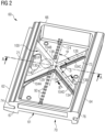
- the stiffening structure 100 For the present heatshield 60, there is a stiffening structure 100 provided that extends from the leading hook 74 to the trailing hook 76 and which is free from contact or attachment to the second surface 72. In this way the stiffening structure does not deflect or distort when the main body 61 and hence second surface 72 is deformed. The stiffening structure 100 does not attach to the second surface or the main body 61 directly. The stiffening structure 100 is spaced apart from the second surface 72 and forms a gap 102 therebetween.
- the stiffening structure 100 is arranged in the general form of an X (or an X-shaped element) when looking towards the second surface 72 from a radially outward position.
- the dotted lines further indicate a generally regular X-shaped arrangement of the stiffening structure 100.
- the stiffening structure 100 has four arms generally referenced 104, with leading arms 104A, 104B located toward the leading edge 62 of the heatshield 60 and attached to the leading hook 74 and trailing arms 104C, 104D located towards the trailing edge 64 of the heatshield 60 and attached to the trailing hook 76.
- Figure 4 is a view looking radially inwardly at an alternative embodiment of the heatshield 60 and showing a second alternative stiffening structure 100.
- FIG. 5 is a view looking radially inwardly at an alternative embodiment of the heatshield 60 and showing a third alternative stiffening structure 100.
- the stiffening structure 100 is similar to that shown and described with reference to Figure 3 and 4 except that there are two additional 'central' arms 104E and 104F.
- Arm 104E attaches to the forward hook 74 and arm 104F attaches to the rearward hook 76.
- the two arms 104E and 104F are arranged in line with the centre line 21 of the heatshield 60.
- the remaining arms 104A and 104B are symmetrical about centre line 21 as to arms 104C and 104D are also symmetrical about centre line 21.
- stiffening structure 100 may be designed to accommodate and combat deformation of the heatshield 60.
- the key feature of the stiffening structure 100 is that it is not in direct contact with the second surface 72 and therefore not only does it remain relatively cool having no direct thermally conductive route (only via the hooks 74, 76), but it is also not subject to thermal distortion of the main body 61 and second surface 72 directly.
- Figure 6 is a section B-B, shown in Figure 2 , through an arm 104 of the stiffening structure 100.
- the arm 104 has the general shape of an I-beam 142 having two flanges 106, 108 and a web 110.
- the sizing of the I-beam 142 and sectional dimensions of the flanges 106, 108 and web 110 is well known in the art for accommodating loads to provide a required stiffness and limit deflections of the heatshield 60.
- Figure 7 is an alternative embodiment of section B-B, shown in Figure 2 , through the arm 104 of the stiffening structure 100.
- the arm 104 has the general shape of a box-beam 144 having, structurally-speaking, two flanges 116, 118 and two web 120, 122.
- the sizing of the box-beam 144 and sectional dimensions of the flanges 106, 108 and web 110 is well known in the art for accommodating loads to provide a required stiffness and limit deflections of the heatshield 60.
- Figure 8 is an alternative embodiment of section B-B, shown in Figure 2 , through the arm 104 of the stiffening structure 100.
- the arm 104 has the general shape of a T-beam 146 having, structurally-speaking, one flange 147 and one web 148.
- the sizing of the T-beam 146 and sectional dimensions of the flange 147 and web 148 is well known in the art for accommodating loads to provide a required stiffness and limit deflections of the heatshield 60.
- a line 124 is defined in the circumferential direction and which is perpendicular to the centre line 21 of the heatshield 60.
- An angle ⁇ is defined between a centre-line 126 of an arm 104 and the line 124; and an angle ⁇ is defined between two arms 104.
- the ratio of angles should be angle ⁇ / angle ⁇ ⁇ 2.
- One reason for this ratio is to ensure that there is a minimum angle of any feature that is 45° without being supported during the manufacturing process. Angle of features less than 45° requires supporting to give the necessary build quality and in this case an undesirable further machining process would be required to remove the supporting feature.
- the centre-lines 126 of the arms 104 intersect at a point 128.
- Point 128 is mid-way between the two hooks 74, 76, but can be located within the middle third of the distance between the two hooks 74, 76.
- Point 128 is located on the centre line 21 of the heatshield 60. Indeed, the four arms 104 meet at an intersection 129 and within which is the point 128.
- the carrier 58 is generally annular and carries the annular array of heatshields 60 that surrounds the rotor stage as previously mentioned.
- the carrier 58 comprises an annular gallery or chamber 79 which is supplied with coolant 80.
- the carrier 58 has an aperture 81, one of an array of apertures 81 arranged about the carrier 58; each aperture 81 feeds a portion of the coolant 80 to one heatshield 60 of the array of heatshields 60 and each aperture 81 is arranged centrally with respect to the centre-line 21 of a respective heatshield 60.
- the coolant 80 forms a jet of coolant that would otherwise impinge on the second surface 72 of the main body 61. This impinging jet of coolant 80 would cause a cold region and increase the temperature gradient across the main body 61.
- the inlets 92 are located radially inwardly of the aperture 81 or in other embodiments the inlets 92 may be located in-line with the jet of coolant 80 passing through the aperture 81. This jet of coolant 80 would otherwise impinge on the second surface 72 and some of the inlets 92 and cause an increase in the dynamic pressure of coolant entering these affected inlets 92.
- some of the inlets 92 and their respective cooling channels 86 would otherwise have a greater mass flow of coolant therethrough compared to those inlets 92 and cooling channels 86 that are not impinged upon. This would otherwise cause irregular cooling of the main body 61 and potentially increase the temperature gradient thereacross and limit the longevity of the heatshield 60 or potentially cause the heatshield to distort with the previously mentioned disadvantages.
- the radially outer web 104 of the stiffening structure 100 has an extended portion 130 that extends between leading arms 104A, 104B.
- the extended portion 130 is located radially inwardly of the aperture 81 and is sized to cover at least the inlets 92 from the jet of coolant 80.
- 'Relevant' inlets 92 meaning those inlets 92 that would otherwise be impinged upon were it not for the provision of the extended portion 130.
- Figure 2 shows a dashed circular line 81P which is a projection of the aperture 81 onto the stiffening structure 100.
- the projection is along a centre-line 132 of the aperture 81 which is aligned with a radial line with respect to the centre-line 20 of the engine 10 (see Figure 3 ); however, the projection can be in the direction of the coolant 80 passing through the aperture 81.
- the aperture 81 may be arranged at an angle away from a radial line and therefore the centre-line 132 and direction of the jet of coolant 80 would also be angled away from the radial line. This angle may be in the circumferential direction and/or the axial direction.
- extended portion 130 may extend between any one or more of the pairs of arms: arm 104A and arm 104B, arm 104B and arm 104C, arm 104C and arm 104D and arm 104 A and arm 104D in order to block the jet of coolant 80 from impinging on the inlets 92 and/or second surface 72.
- the arms 104 are provided with a radiused intersection or blend radius 134, 136, 138 where they join each other and/or the hooks 74, 76.
- Blend radius 134 is formed on an obtuse angle with the hooks 74, 76;
- blend radius 136 is formed on an acute angle with the hooks 74, 76;
- the blend radius 138 is formed between any one or more of the pairs of arms: arm 104A and arm 104B, arm 104B and arm 104C, arm 104C and arm 104D and arm 104 A and arm 104D.
- it is the webs 104, 108 that comprise the blend radius 134, 136, 138.
- the box-beam's two flanges 116, 118 and two webs 120, 122 will all comprise blend radii 134, 136, 138.
- the purpose of the radius is to reduce stress concentration at joints.
- the stiffening structure 100 defines an aperture 140 between the front hook 74, the arms 104A and 104B and the extended portion 130 of the radially outer web 104 (or 120).
- the aperture 140 is shaped by virtue of the blend radii 136 and the extended portion 130 being of minimum size to deflect the jet of coolant 80.
- the aperture 140 allows coolant through to the second surface 72 so that the pressure of the coolant over the second surface 72 is as even as possible.
- the overall area of the stiffening structure 100 when looking radially inwardly, is minimised and in consideration of a function of the structural stiffness / distortion requirements of the heatshield 60, deflection of the jet of coolant 80 via the extended portion 130 and the desire to evenly distribute the coolant 80.
- FIG. 9 is a view looking radially inwardly at an alternative embodiment of the heatshield 60 and showing a fourth alternative stiffening structure 100 and FIG. 10 is a cross-section C-C through the fourth alternative.
- the stiffening structure 100 is a lattice arrangement 150.
- the lattice arrangement 150 is a plate 152 having a thickness 154 which in this embodiment is approximately a constant thickness.
- the lattice arrangement 150 is the plate 154 having an array of apertures 155 having a number of differently sized apertures 156, 158, 160 to suit the structural stiffening requirements or more accurately the remaining structure provides the required stiffness and structural performance to the heatshield.
- the lattice arrangement 150 shown in FIG. 9 is one example and is particularly suited to this heatshield 60; however, there are a multitude of different arrangements that are possible for this and other heatshield applications and stress-strain calculations are well known the skilled person in designing any particular arrangement to primarily stiffen the hooks 74, 76 whilst keeping the stiffening structure 100 free from direct contact with the second surface 72.
- the lattice arrangement 150 has a frame 162 defining the periphery of the stiffening structure 100 and alternatively the lattice arrangement 100 may not have a frame 162.
- the lattice arrangement 150 may have a regular arrangement of diamond-shaped apertures 156 with triangular-shaped apertures 158 against the edges or frame of the lattice arrangement.
- the remaining material may form straight 'strips' of material in a conventional criss-cross pattern or array of X-shaped elements having arms.
- This array of X-shaped arms (these arms are analogous to the fours arms 104A, 104B, 104C, 104D meeting at an intersection 129), except that some arms of one X-shaped element are continuous with some of the arms of the next X-shaped element either in the direction from the leading hoot 74 to trailing hook 76 and/or from one lateral edge 66 to the other lateral edge 67.
- these arms are generally rectangular 151 in shape as shown in FIG. 10 .
- the lattice arrangement 150 is connected to the leading hook 74 and trailing hook 76 along their circumferential lengths and performs the same structural benefits as previously described.
- the apertures 156, 158, 160 may be located and/or sized to also provide a shield, i.e. extended portion 130 shown in dashed lines, for the impingement of the cooling flow 80 as previously described.
- the shape of the stiffening structure 100 is such that good quality manufacturing is possible, particularly considering the preferred method is 3D-printing or additive-manufacturing.
- the stiffening structure 100 is formed integrally or is monolithic with the hooks 74, 76 and indeed the entire heatshield is monolithic, being built from a layer-by-layer continuous process.
- 'printability' is a significant consideration in the design of the heatshield and the stiffening structure in particular.
- one key feature is that the stiffening structure is detached from the main body 61 and/or second surface 72 of the additively-manufactured heatshield.
- the present heatshield 60 is advantageous because it has increased stiffness to prevent distortion and is better sealed around its edges 62, 64, 66, 67 than previous designs; the addition of the stiffening structure 100 spanning directly between hooks 74 and 76 means that it is surrounded by coolant and does not directly pick up heat from the main body 61 and is therefore inherently stiffer than previous designs; the extended portion 130 improves even distribution of coolant into the inlets and cooling channels in the main body to provide a more evenly cooled main body 61 with associated benefits mentioned hereinbefore.
- Temperature capability meaning that the hot working gases can be at a higher temperature than before because of the improved heat management of the present heatshield compared to previous and conventional designs.
- the presently described heatshield 60 is particularly suited to manufacture by an additive manufacturing process such as direct laser deposition, laser sintering, select laser melting or other 3D printing techniques.
- the direction of formation of the heatshield 60 is, layer-by-layer, from one lateral edge 61 towards the other and specifically in the direction of the line 124 in Figure 2 .
Landscapes
- Engineering & Computer Science (AREA)
- Mechanical Engineering (AREA)
- General Engineering & Computer Science (AREA)
- Chemical & Material Sciences (AREA)
- Combustion & Propulsion (AREA)
- Turbine Rotor Nozzle Sealing (AREA)
Claims (14)
- Hitzeschild (60) für einen Gasturbinenmotor (10), wobei der Hitzeschild (60) umfasst:einen Hauptkörper (61) mit einer vorderen Kante (62), einer hinteren Kante (64), Seitenkanten (66, 67), einer ersten Oberfläche (70) und einer zweiten Oberfläche (72), wobei die erste Oberfläche (70) bei Gebrauch einem heißen Arbeitsgas ausgesetzt ist, das den Gasturbinenmotor (10) durchläuft,einen vorderen Haken (74) und einen hinteren Haken (76), die sich jeweils zwischen den Seitenrändern (66, 67) erstrecken, wobei der vordere Haken (74) und der hintere Haken (76) sich von der zweiten Oberfläche (72) erstrecken,gekennzeichnet durcheine Versteifungsstruktur (100), die sich von dem vorderen Haken (74) zu dem hinteren Haken (76) erstreckt und frei von direktem Kontakt oder Anbringung an der zweiten Oberfläche (72) ist, wobei die Versteifungsstruktur (100) mit dem vorderen Haken (74) und dem hinteren Haken (76) monolithisch ist.
- Hitzeschild (60) nach Anspruch 1, wobei die Versteifungsstruktur (100) in der allgemeinen Form von mindestens einem X angeordnet ist, wenn in Richtung der zweiten Oberfläche (72) geblickt wird.
- Hitzeschild (60) nach Anspruch 2, wobei die Versteifungsstruktur (100) vier Arme (104A, 104B, 104C, 104D) umfasst,wobei zwei Arme (104A, 104B) an dem vorderen Haken (74) angebracht sind und zwei Arme (104C, 104D) an dem hinteren Haken (76) angebracht sind,wobei die vier Arme (104A, 104B, 104C, 104D) sich an einem Kreuzungspunkt (129) treffen.
- Hitzeschild (60) nach Anspruch 3, wobei die Versteifungsstruktur (100) einen Verlängerungsabschnitt (130) umfasst,wobei der Verlängerungsabschnitt (130) sich zwischen jeglichem einen oder jeglichen mehreren der Paare von Armen, Arm (104A) und Arm (104B), Arm (104B) und Arm (104C), Arm (104C) und Arm (104D), und Arm (104A) und Arm (104D) erstreckt,der Verlängerungsabschnitt (130) bei Gebrauch den Strahl des Kühlmittels (80) am Auftreffen auf die zweite Oberfläche (72) und/oder mindestens einen in der zweiten Oberfläche (72) definierten Einlass (92) hindert.
- Hitzeschild (60) nach Anspruch 4, umfassend eine Mittellinie (21) und senkrecht zu der Mittellinie (21) eine Linie (124),wobei ein Winkel (α) von einem Arm (104C) zu der Linie (124) definiert ist, und ein Winkel (β) von dem Arm (104C) zu einem anderen Arm (104D) definiert ist, wobei beide Arme (104C, 104D) an dem gleichen vorderen oder hinteren Haken (74, 76) angebracht sind,wobei das Verhältnis der Winkel Winkel α/Winkel β ≥ 2 ist.
- Hitzeschild (60) nach einem der Ansprüche 4 bis 5, wobei die Versteifungsstruktur (100) einen oder mehreren von den Querschnittprofilen I-Balken (142), T-Balken, Kastenbalken (144) oder Rechteck (151) umfasst.
- Hitzeschild (60) nach einem der Ansprüche 4 bis 6, wobei die Versteifungsstruktur eine Balkenanordnung (101) ist, wobei die Balkenanordnung (101) mindestens einen Balken (104A, 104B, 104C, 104D, 104E, 104F) umfasst, wobei der mindestens eine Balken (104A, 104B, 104C, 104D, 104E, 104F) mindestens einen Steg (110, 116, 118, 148) und mindestens einen Flansch (106, 108, 120, 122, 147) aufweist.
- Hitzeschild (60) nach Anspruch 7, wobei der Verlängerungsabschnitt (130) durch eine Verlängerung des Flansches (106, 108, 120, 122, 147), vorzugsweise des radialen äußeren Flansches (106, 120, 147) gebildet ist.
- Hitzeschild (60) nach einem der Ansprüche 1 bis 6, wobei die Versteifungsstruktur (100) eine Gitterstruktur (150) ist.
- Hitzeschild (60) nach Anspruch 9, wobei die Gitterstruktur (150) eine Gruppierung X-förmiger Elemente ist, wobei jedes X-förmige Element Arme (104A, 104B, 104C, 104D) aufweist.
- Hitzeschild (60) nach einem der Ansprüche 1 bis 10, wobei der Verlängerungsabschnitt (130) nicht mit entweder dem vorderen Haken (74) oder dem hinteren Haken (76) verbunden ist.
- Gasturbinenmotor (10), umfassend den Hitzeschild (60) nach einem der Ansprüche 1 bis 11 und einen Träger (58),
wobei der Träger (58) radial auswärts von dem Hitzeschild (60) positioniert ist und umfasst:entsprechende Eingriffmerkmale (75, 77) zum Eingriff mit dem vorderen Haken (74) und dem hinteren Haken (76) undmindestens eine Öffnung (81) zum Lenken von Kühlmittel (80) durch diese hindurch und in Richtung des Hitzeschilds (60), wobei die mindestens eine Öffnung (81) eine Mittellinie (132) aufweist,wobei die Mittellinie (132) die Versteifungsstruktur (100) kreuzt, so dass das Kühlmittel (80) mindestens teilweise auf die Versteifungsstruktur (100) auftrifft. - Gasturbinenmotor (10) nach Anspruch 12 in Abhängigkeit von Anspruch 4 und jeglichem von Anspruch 4 abhängigen Anspruch, wobei
die Mittellinie (132) die Versteifungsstruktur (100) kreuzt, so dass das Kühlmittel (80) mindestens teilweise auf dem Verlängerungsabschnitt (130) auftrifft. - Gasturbinenmotor (10) nach einem der Ansprüche 12 bis 13,wobei der Hitzeschild (60) einer von einer kranzförmigen Gruppierung von Hitzeschilden (60) ist und der Träger (58) kranzförmig ist,der Träger (58) eine kranzförmige Gruppierung von Öffnungen (81) umfasst,die Mittellinie (132) von jeder Öffnung radial mit einem der Hitzeschilde (60) und insbesondere einer von der Versteifungsstruktur (100) ausgerichtet ist, so dass bei Gebrauch Kühlmittel auf den Hitzeschild (60) und insbesondere die Versteifungsstruktur (100) auftrifft.
Applications Claiming Priority (2)
| Application Number | Priority Date | Filing Date | Title |
|---|---|---|---|
| GBGB1907545.6A GB201907545D0 (en) | 2019-05-29 | 2019-05-29 | Heatshield for a gas turbine engine |
| PCT/EP2020/064027 WO2020239560A1 (en) | 2019-05-29 | 2020-05-20 | Heatshield for a gas turbine engine |
Publications (3)
| Publication Number | Publication Date |
|---|---|
| EP3976933A1 EP3976933A1 (de) | 2022-04-06 |
| EP3976933B1 true EP3976933B1 (de) | 2024-01-03 |
| EP3976933C0 EP3976933C0 (de) | 2024-01-03 |
Family
ID=67385381
Family Applications (1)
| Application Number | Title | Priority Date | Filing Date |
|---|---|---|---|
| EP20732110.0A Active EP3976933B1 (de) | 2019-05-29 | 2020-05-20 | Hitzeschild für einen gasturbinenmotor |
Country Status (6)
| Country | Link |
|---|---|
| US (1) | US12025019B2 (de) |
| EP (1) | EP3976933B1 (de) |
| CN (1) | CN113950566B (de) |
| CA (1) | CA3142104A1 (de) |
| GB (1) | GB201907545D0 (de) |
| WO (1) | WO2020239560A1 (de) |
Citations (1)
| Publication number | Priority date | Publication date | Assignee | Title |
|---|---|---|---|---|
| EP1965032B1 (de) * | 2007-03-01 | 2015-05-06 | United Technologies Corporation | Außendichtung für eine Turbinenschaufel |
Family Cites Families (15)
| Publication number | Priority date | Publication date | Assignee | Title |
|---|---|---|---|---|
| SU838290A1 (ru) | 1979-09-12 | 1981-06-15 | Уральский Научно-Исследовательскийи Проектный Институт Строительныхматериалов | Плоский подвесной свод туннельной печи |
| US4526226A (en) * | 1981-08-31 | 1985-07-02 | General Electric Company | Multiple-impingement cooled structure |
| JPH06105048B2 (ja) | 1991-05-28 | 1994-12-21 | ゼネラル・エレクトリック・カンパニイ | コアフレームを静翼フレームに安定中央リングで着脱自在に取付ける装置 |
| US5738490A (en) * | 1996-05-20 | 1998-04-14 | Pratt & Whitney Canada, Inc. | Gas turbine engine shroud seals |
| US6932568B2 (en) | 2003-02-27 | 2005-08-23 | General Electric Company | Turbine nozzle segment cantilevered mount |
| FR2857406B1 (fr) * | 2003-07-10 | 2005-09-30 | Snecma Moteurs | Refroidissement des anneaux de turbine |
| US7553128B2 (en) * | 2006-10-12 | 2009-06-30 | United Technologies Corporation | Blade outer air seals |
| US7665962B1 (en) * | 2007-01-26 | 2010-02-23 | Florida Turbine Technologies, Inc. | Segmented ring for an industrial gas turbine |
| US8251637B2 (en) * | 2008-05-16 | 2012-08-28 | General Electric Company | Systems and methods for modifying modal vibration associated with a turbine |
| US8118548B2 (en) * | 2008-09-15 | 2012-02-21 | General Electric Company | Shroud for a turbomachine |
| EP2270395B1 (de) | 2009-06-09 | 2015-01-14 | Siemens Aktiengesellschaft | Hitzeschildelementanordnung und Verfahren zur Montage eines Hitzeschildelementes |
| US8845285B2 (en) * | 2012-01-10 | 2014-09-30 | General Electric Company | Gas turbine stator assembly |
| US9797262B2 (en) | 2013-07-26 | 2017-10-24 | United Technologies Corporation | Split damped outer shroud for gas turbine engine stator arrays |
| EP3048262A1 (de) | 2015-01-20 | 2016-07-27 | Alstom Technology Ltd | Wand für einen Heißgaskanal in einer Gasturbine |
| GB201610309D0 (en) * | 2016-06-14 | 2016-07-27 | Rolls Royce Plc | A semi-annular component and method of manufacture |
-
2019
- 2019-05-29 GB GBGB1907545.6A patent/GB201907545D0/en not_active Ceased
-
2020
- 2020-05-20 EP EP20732110.0A patent/EP3976933B1/de active Active
- 2020-05-20 US US17/609,375 patent/US12025019B2/en active Active
- 2020-05-20 CA CA3142104A patent/CA3142104A1/en active Pending
- 2020-05-20 CN CN202080038943.7A patent/CN113950566B/zh active Active
- 2020-05-20 WO PCT/EP2020/064027 patent/WO2020239560A1/en not_active Ceased
Patent Citations (1)
| Publication number | Priority date | Publication date | Assignee | Title |
|---|---|---|---|---|
| EP1965032B1 (de) * | 2007-03-01 | 2015-05-06 | United Technologies Corporation | Außendichtung für eine Turbinenschaufel |
Also Published As
| Publication number | Publication date |
|---|---|
| US12025019B2 (en) | 2024-07-02 |
| CN113950566B (zh) | 2024-06-14 |
| US20220213809A1 (en) | 2022-07-07 |
| EP3976933C0 (de) | 2024-01-03 |
| CN113950566A (zh) | 2022-01-18 |
| EP3976933A1 (de) | 2022-04-06 |
| GB201907545D0 (en) | 2019-07-10 |
| WO2020239560A1 (en) | 2020-12-03 |
| CA3142104A1 (en) | 2020-12-03 |
Similar Documents
| Publication | Publication Date | Title |
|---|---|---|
| JP3671981B2 (ja) | 曲折した冷却用チャネルを備えたタービンシュラウドセグメント | |
| EP1452689B1 (de) | Gasturbinenstatorschaufelsegment mit einem zweigeteilten Hohlraum | |
| US6017189A (en) | Cooling system for turbine blade platforms | |
| US7008185B2 (en) | Gas turbine engine turbine nozzle bifurcated impingement baffle | |
| JP5345310B2 (ja) | タービンエンジンの冷却を促進するシステム及びガスタービンエンジン | |
| EP3318720B1 (de) | Gekühlte struktur für eine gasturbine, zugehörige gasturbine und verfahren zur herstellung einer gekühlten struktur | |
| EP1927725B1 (de) | System zum Erleichtern einer bevorzugt verteilten rekuperierten Filmkühlung in einer Turbinendeckbandanordnung | |
| US4280792A (en) | Air-cooled turbine rotor shroud with restraints | |
| EP1452693A2 (de) | Turbinenleitschaufelträger | |
| US11905886B2 (en) | Heatshield for a gas turbine engine | |
| US11015481B2 (en) | Turbine shroud block segment with near surface cooling channels | |
| US7588412B2 (en) | Cooled shroud assembly and method of cooling a shroud | |
| EP3976933B1 (de) | Hitzeschild für einen gasturbinenmotor | |
| US11293639B2 (en) | Heatshield for a gas turbine engine | |
| RU2788802C1 (ru) | Тепловой экран для газотурбинного двигателя |
Legal Events
| Date | Code | Title | Description |
|---|---|---|---|
| STAA | Information on the status of an ep patent application or granted ep patent |
Free format text: STATUS: UNKNOWN |
|
| STAA | Information on the status of an ep patent application or granted ep patent |
Free format text: STATUS: THE INTERNATIONAL PUBLICATION HAS BEEN MADE |
|
| PUAI | Public reference made under article 153(3) epc to a published international application that has entered the european phase |
Free format text: ORIGINAL CODE: 0009012 |
|
| STAA | Information on the status of an ep patent application or granted ep patent |
Free format text: STATUS: REQUEST FOR EXAMINATION WAS MADE |
|
| 17P | Request for examination filed |
Effective date: 20211029 |
|
| AK | Designated contracting states |
Kind code of ref document: A1 Designated state(s): AL AT BE BG CH CY CZ DE DK EE ES FI FR GB GR HR HU IE IS IT LI LT LU LV MC MK MT NL NO PL PT RO RS SE SI SK SM TR |
|
| DAV | Request for validation of the european patent (deleted) | ||
| DAX | Request for extension of the european patent (deleted) | ||
| GRAP | Despatch of communication of intention to grant a patent |
Free format text: ORIGINAL CODE: EPIDOSNIGR1 |
|
| STAA | Information on the status of an ep patent application or granted ep patent |
Free format text: STATUS: GRANT OF PATENT IS INTENDED |
|
| INTG | Intention to grant announced |
Effective date: 20230904 |
|
| GRAS | Grant fee paid |
Free format text: ORIGINAL CODE: EPIDOSNIGR3 |
|
| GRAA | (expected) grant |
Free format text: ORIGINAL CODE: 0009210 |
|
| STAA | Information on the status of an ep patent application or granted ep patent |
Free format text: STATUS: THE PATENT HAS BEEN GRANTED |
|
| AK | Designated contracting states |
Kind code of ref document: B1 Designated state(s): AL AT BE BG CH CY CZ DE DK EE ES FI FR GB GR HR HU IE IS IT LI LT LU LV MC MK MT NL NO PL PT RO RS SE SI SK SM TR |
|
| REG | Reference to a national code |
Ref country code: GB Ref legal event code: FG4D |
|
| REG | Reference to a national code |
Ref country code: DE Ref legal event code: R096 Ref document number: 602020023833 Country of ref document: DE |
|
| REG | Reference to a national code |
Ref country code: CH Ref legal event code: EP |
|
| REG | Reference to a national code |
Ref country code: IE Ref legal event code: FG4D |
|
| U01 | Request for unitary effect filed |
Effective date: 20240117 |
|
| U07 | Unitary effect registered |
Designated state(s): AT BE BG DE DK EE FI FR IT LT LU LV MT NL PT SE SI Effective date: 20240125 |
|
| PG25 | Lapsed in a contracting state [announced via postgrant information from national office to epo] |
Ref country code: ES Free format text: LAPSE BECAUSE OF FAILURE TO SUBMIT A TRANSLATION OF THE DESCRIPTION OR TO PAY THE FEE WITHIN THE PRESCRIBED TIME-LIMIT Effective date: 20240103 |
|
| PG25 | Lapsed in a contracting state [announced via postgrant information from national office to epo] |
Ref country code: ES Free format text: LAPSE BECAUSE OF FAILURE TO SUBMIT A TRANSLATION OF THE DESCRIPTION OR TO PAY THE FEE WITHIN THE PRESCRIBED TIME-LIMIT Effective date: 20240103 |
|
| PG25 | Lapsed in a contracting state [announced via postgrant information from national office to epo] |
Ref country code: IS Free format text: LAPSE BECAUSE OF FAILURE TO SUBMIT A TRANSLATION OF THE DESCRIPTION OR TO PAY THE FEE WITHIN THE PRESCRIBED TIME-LIMIT Effective date: 20240503 |
|
| U20 | Renewal fee for the european patent with unitary effect paid |
Year of fee payment: 5 Effective date: 20240527 |
|
| PG25 | Lapsed in a contracting state [announced via postgrant information from national office to epo] |
Ref country code: GR Free format text: LAPSE BECAUSE OF FAILURE TO SUBMIT A TRANSLATION OF THE DESCRIPTION OR TO PAY THE FEE WITHIN THE PRESCRIBED TIME-LIMIT Effective date: 20240404 |
|
| PG25 | Lapsed in a contracting state [announced via postgrant information from national office to epo] |
Ref country code: HR Free format text: LAPSE BECAUSE OF FAILURE TO SUBMIT A TRANSLATION OF THE DESCRIPTION OR TO PAY THE FEE WITHIN THE PRESCRIBED TIME-LIMIT Effective date: 20240103 Ref country code: RS Free format text: LAPSE BECAUSE OF FAILURE TO SUBMIT A TRANSLATION OF THE DESCRIPTION OR TO PAY THE FEE WITHIN THE PRESCRIBED TIME-LIMIT Effective date: 20240403 |
|
| PG25 | Lapsed in a contracting state [announced via postgrant information from national office to epo] |
Ref country code: CZ Free format text: LAPSE BECAUSE OF FAILURE TO SUBMIT A TRANSLATION OF THE DESCRIPTION OR TO PAY THE FEE WITHIN THE PRESCRIBED TIME-LIMIT Effective date: 20240103 |
|
| PG25 | Lapsed in a contracting state [announced via postgrant information from national office to epo] |
Ref country code: RS Free format text: LAPSE BECAUSE OF FAILURE TO SUBMIT A TRANSLATION OF THE DESCRIPTION OR TO PAY THE FEE WITHIN THE PRESCRIBED TIME-LIMIT Effective date: 20240403 Ref country code: NO Free format text: LAPSE BECAUSE OF FAILURE TO SUBMIT A TRANSLATION OF THE DESCRIPTION OR TO PAY THE FEE WITHIN THE PRESCRIBED TIME-LIMIT Effective date: 20240403 Ref country code: IS Free format text: LAPSE BECAUSE OF FAILURE TO SUBMIT A TRANSLATION OF THE DESCRIPTION OR TO PAY THE FEE WITHIN THE PRESCRIBED TIME-LIMIT Effective date: 20240503 Ref country code: HR Free format text: LAPSE BECAUSE OF FAILURE TO SUBMIT A TRANSLATION OF THE DESCRIPTION OR TO PAY THE FEE WITHIN THE PRESCRIBED TIME-LIMIT Effective date: 20240103 Ref country code: GR Free format text: LAPSE BECAUSE OF FAILURE TO SUBMIT A TRANSLATION OF THE DESCRIPTION OR TO PAY THE FEE WITHIN THE PRESCRIBED TIME-LIMIT Effective date: 20240404 Ref country code: CZ Free format text: LAPSE BECAUSE OF FAILURE TO SUBMIT A TRANSLATION OF THE DESCRIPTION OR TO PAY THE FEE WITHIN THE PRESCRIBED TIME-LIMIT Effective date: 20240103 |
|
| PG25 | Lapsed in a contracting state [announced via postgrant information from national office to epo] |
Ref country code: PL Free format text: LAPSE BECAUSE OF FAILURE TO SUBMIT A TRANSLATION OF THE DESCRIPTION OR TO PAY THE FEE WITHIN THE PRESCRIBED TIME-LIMIT Effective date: 20240103 |
|
| PG25 | Lapsed in a contracting state [announced via postgrant information from national office to epo] |
Ref country code: PL Free format text: LAPSE BECAUSE OF FAILURE TO SUBMIT A TRANSLATION OF THE DESCRIPTION OR TO PAY THE FEE WITHIN THE PRESCRIBED TIME-LIMIT Effective date: 20240103 |
|
| REG | Reference to a national code |
Ref country code: DE Ref legal event code: R097 Ref document number: 602020023833 Country of ref document: DE |
|
| PG25 | Lapsed in a contracting state [announced via postgrant information from national office to epo] |
Ref country code: SM Free format text: LAPSE BECAUSE OF FAILURE TO SUBMIT A TRANSLATION OF THE DESCRIPTION OR TO PAY THE FEE WITHIN THE PRESCRIBED TIME-LIMIT Effective date: 20240103 |
|
| PG25 | Lapsed in a contracting state [announced via postgrant information from national office to epo] |
Ref country code: SK Free format text: LAPSE BECAUSE OF FAILURE TO SUBMIT A TRANSLATION OF THE DESCRIPTION OR TO PAY THE FEE WITHIN THE PRESCRIBED TIME-LIMIT Effective date: 20240103 |
|
| PG25 | Lapsed in a contracting state [announced via postgrant information from national office to epo] |
Ref country code: SM Free format text: LAPSE BECAUSE OF FAILURE TO SUBMIT A TRANSLATION OF THE DESCRIPTION OR TO PAY THE FEE WITHIN THE PRESCRIBED TIME-LIMIT Effective date: 20240103 Ref country code: SK Free format text: LAPSE BECAUSE OF FAILURE TO SUBMIT A TRANSLATION OF THE DESCRIPTION OR TO PAY THE FEE WITHIN THE PRESCRIBED TIME-LIMIT Effective date: 20240103 Ref country code: RO Free format text: LAPSE BECAUSE OF FAILURE TO SUBMIT A TRANSLATION OF THE DESCRIPTION OR TO PAY THE FEE WITHIN THE PRESCRIBED TIME-LIMIT Effective date: 20240103 |
|
| PLBE | No opposition filed within time limit |
Free format text: ORIGINAL CODE: 0009261 |
|
| STAA | Information on the status of an ep patent application or granted ep patent |
Free format text: STATUS: NO OPPOSITION FILED WITHIN TIME LIMIT |
|
| 26N | No opposition filed |
Effective date: 20241007 |
|
| REG | Reference to a national code |
Ref country code: CH Ref legal event code: PL |
|
| PG25 | Lapsed in a contracting state [announced via postgrant information from national office to epo] |
Ref country code: MC Free format text: LAPSE BECAUSE OF FAILURE TO SUBMIT A TRANSLATION OF THE DESCRIPTION OR TO PAY THE FEE WITHIN THE PRESCRIBED TIME-LIMIT Effective date: 20240103 |
|
| GBPC | Gb: european patent ceased through non-payment of renewal fee |
Effective date: 20240520 |
|
| PG25 | Lapsed in a contracting state [announced via postgrant information from national office to epo] |
Ref country code: MC Free format text: LAPSE BECAUSE OF FAILURE TO SUBMIT A TRANSLATION OF THE DESCRIPTION OR TO PAY THE FEE WITHIN THE PRESCRIBED TIME-LIMIT Effective date: 20240103 Ref country code: CH Free format text: LAPSE BECAUSE OF NON-PAYMENT OF DUE FEES Effective date: 20240531 |
|
| PG25 | Lapsed in a contracting state [announced via postgrant information from national office to epo] |
Ref country code: IE Free format text: LAPSE BECAUSE OF NON-PAYMENT OF DUE FEES Effective date: 20240520 |
|
| PG25 | Lapsed in a contracting state [announced via postgrant information from national office to epo] |
Ref country code: GB Free format text: LAPSE BECAUSE OF NON-PAYMENT OF DUE FEES Effective date: 20240520 |
|
| U20 | Renewal fee for the european patent with unitary effect paid |
Year of fee payment: 6 Effective date: 20250526 |
|
| PG25 | Lapsed in a contracting state [announced via postgrant information from national office to epo] |
Ref country code: CY Free format text: LAPSE BECAUSE OF FAILURE TO SUBMIT A TRANSLATION OF THE DESCRIPTION OR TO PAY THE FEE WITHIN THE PRESCRIBED TIME-LIMIT; INVALID AB INITIO Effective date: 20200520 |
|
| PG25 | Lapsed in a contracting state [announced via postgrant information from national office to epo] |
Ref country code: HU Free format text: LAPSE BECAUSE OF FAILURE TO SUBMIT A TRANSLATION OF THE DESCRIPTION OR TO PAY THE FEE WITHIN THE PRESCRIBED TIME-LIMIT; INVALID AB INITIO Effective date: 20200520 |